EP3361647A1 - Apparatuses and methods for beam sweeping in a wireless communication system - Google Patents
Apparatuses and methods for beam sweeping in a wireless communication system Download PDFInfo
- Publication number
- EP3361647A1 EP3361647A1 EP18156574.8A EP18156574A EP3361647A1 EP 3361647 A1 EP3361647 A1 EP 3361647A1 EP 18156574 A EP18156574 A EP 18156574A EP 3361647 A1 EP3361647 A1 EP 3361647A1
- Authority
- EP
- European Patent Office
- Prior art keywords
- signals
- beams
- wireless communication
- communication device
- wireless
- Prior art date
- Legal status (The legal status is an assumption and is not a legal conclusion. Google has not performed a legal analysis and makes no representation as to the accuracy of the status listed.)
- Granted
Links
Images




Classifications
-
- H—ELECTRICITY
- H04—ELECTRIC COMMUNICATION TECHNIQUE
- H04B—TRANSMISSION
- H04B7/00—Radio transmission systems, i.e. using radiation field
- H04B7/02—Diversity systems; Multi-antenna system, i.e. transmission or reception using multiple antennas
- H04B7/04—Diversity systems; Multi-antenna system, i.e. transmission or reception using multiple antennas using two or more spaced independent antennas
- H04B7/0404—Diversity systems; Multi-antenna system, i.e. transmission or reception using multiple antennas using two or more spaced independent antennas the mobile station comprising multiple antennas, e.g. to provide uplink diversity
-
- H—ELECTRICITY
- H04—ELECTRIC COMMUNICATION TECHNIQUE
- H04B—TRANSMISSION
- H04B7/00—Radio transmission systems, i.e. using radiation field
- H04B7/02—Diversity systems; Multi-antenna system, i.e. transmission or reception using multiple antennas
- H04B7/04—Diversity systems; Multi-antenna system, i.e. transmission or reception using multiple antennas using two or more spaced independent antennas
- H04B7/06—Diversity systems; Multi-antenna system, i.e. transmission or reception using multiple antennas using two or more spaced independent antennas at the transmitting station
- H04B7/0686—Hybrid systems, i.e. switching and simultaneous transmission
-
- H—ELECTRICITY
- H04—ELECTRIC COMMUNICATION TECHNIQUE
- H04B—TRANSMISSION
- H04B15/00—Suppression or limitation of noise or interference
-
- H—ELECTRICITY
- H04—ELECTRIC COMMUNICATION TECHNIQUE
- H04B—TRANSMISSION
- H04B7/00—Radio transmission systems, i.e. using radiation field
- H04B7/02—Diversity systems; Multi-antenna system, i.e. transmission or reception using multiple antennas
- H04B7/04—Diversity systems; Multi-antenna system, i.e. transmission or reception using multiple antennas using two or more spaced independent antennas
- H04B7/0408—Diversity systems; Multi-antenna system, i.e. transmission or reception using multiple antennas using two or more spaced independent antennas using two or more beams, i.e. beam diversity
-
- H—ELECTRICITY
- H04—ELECTRIC COMMUNICATION TECHNIQUE
- H04B—TRANSMISSION
- H04B7/00—Radio transmission systems, i.e. using radiation field
- H04B7/02—Diversity systems; Multi-antenna system, i.e. transmission or reception using multiple antennas
- H04B7/04—Diversity systems; Multi-antenna system, i.e. transmission or reception using multiple antennas using two or more spaced independent antennas
- H04B7/06—Diversity systems; Multi-antenna system, i.e. transmission or reception using multiple antennas using two or more spaced independent antennas at the transmitting station
- H04B7/0686—Hybrid systems, i.e. switching and simultaneous transmission
- H04B7/0695—Hybrid systems, i.e. switching and simultaneous transmission using beam selection
- H04B7/06952—Selecting one or more beams from a plurality of beams, e.g. beam training, management or sweeping
-
- H—ELECTRICITY
- H04—ELECTRIC COMMUNICATION TECHNIQUE
- H04B—TRANSMISSION
- H04B7/00—Radio transmission systems, i.e. using radiation field
- H04B7/02—Diversity systems; Multi-antenna system, i.e. transmission or reception using multiple antennas
- H04B7/04—Diversity systems; Multi-antenna system, i.e. transmission or reception using multiple antennas using two or more spaced independent antennas
- H04B7/08—Diversity systems; Multi-antenna system, i.e. transmission or reception using multiple antennas using two or more spaced independent antennas at the receiving station
- H04B7/0868—Hybrid systems, i.e. switching and combining
- H04B7/088—Hybrid systems, i.e. switching and combining using beam selection
Definitions
- the application generally relates to wireless communications, and more particularly, to apparatuses and methods for beam sweeping in a wireless communication system (e.g., a fifth-generation (5G) New Radio (NR) system or a Wi-Fi system).
- a wireless communication system e.g., a fifth-generation (5G) New Radio (NR) system or a Wi-Fi system.
- 5G fifth-generation
- NR New Radio
- the fifth generation (5G) New Radio (NR) technology is an improvement upon the fourth generation (4G) Long Term Evolution (LTE) technology, which provides extreme data speeds and capacity, by utilizing higher and unlicensed spectrum bands (e.g., above 30 GHz, loosely known as millimeter Wave (mmWave)), for wireless broadband communications. Due to the huge path and penetration losses at millimeter wavelengths, a technique called "beamforming" is employed and it assumes an important role in establishing and maintaining a robust communication link.
- 4G Long Term Evolution
- mmWave millimeter Wave Due to the huge path and penetration losses at millimeter wavelengths, a technique called “beamforming" is employed and it assumes an important role in establishing and maintaining a robust communication link.
- Beamforming generally requires one or more antenna arrays, each comprising a plurality of antennas.
- antenna weights that define a contribution of each one of the antennas to a transmission or reception operation, it becomes possible to shape the sensitivity of the transmission/reception to a particularly high value in a specific beamformed direction.
- different antenna weights By applying different antenna weights, different beam patterns can be achieved, e.g., different directive beams can be sequentially employed.
- beamforming may direct the signal towards a receiver of interest.
- beamforming may provide a high sensitivity in receiving the signal originating from a sender of interest. Since the transmission power may be anisotropically focused, e.g., into a solid angle of interest, beamforming may provide better link budgets due to lower required Tx power and higher received signal power, when compared to a conventional practice which does not employ beamforming and relies on more or less isotropic transmission.
- Fig. 1 is a schematic diagram illustrating consecutive RACH occasions allocated to a gNB for Rx beam sweeping in a sequential order.
- the ON-OFF transient period for a UE is 5 micro-seconds for carrier frequencies above 24 GHz.
- the 5 micro-seconds transient period of a UE may introduce significant interferences to the UEs attempting to access the gNB in the preceding and following RACH occasions, as shown in Fig. 1 .
- the present application proposes wireless communication devices and beam sweeping methods, in which the beams are configured to be swept in a non-sequential order (e.g., in a beam-interleaving manner), so that inter-Orthogonal frequency-division multiplexing (OFDM)-symbol interferences may be efficiently reduced.
- OFDM inter-Orthogonal frequency-division multiplexing
- a wireless communication device comprising a controller and a non-transitory machine-readable storage medium operatively coupled to the controller.
- the controller is configured to execute program code stored in the non-transitory machine-readable storage medium to perform operations comprising: transmitting or receiving wireless signals by sweeping beams in a non-sequential order.
- a beam sweeping method executed by a wireless communication device, comprises the steps of: transmitting or receiving wireless signals by sweeping beams in a non-sequential order.
- Fig. 2 is a block diagram of a wireless communication environment according to an embodiment of the application.
- the wireless communication environment 100 includes a User Equipment (UE) 110 and a 5G NR network 120, wherein the UE 110 is wirelessly connected to the 5G NR network 120 for obtaining mobile services.
- UE User Equipment
- the UE 110 may be a feature phone, a smartphone, a panel Personal Computer (PC), a laptop computer, or any wireless communication device supporting the wireless technology (i.e., the 5G NR technology) utilized by the 5G NR network 120 and/or the Wireless-Fidelity (Wi-Fi) technology.
- the wireless communication device employs the beamforming technique for wireless transmission and/or reception.
- the 5G NR network 120 includes a Radio Access Network (RAN) 121 and a Next Generation Core Network (NG-CN) 122.
- RAN Radio Access Network
- NG-CN Next Generation Core Network
- the RAN 121 is responsible for processing radio signals, terminating radio protocols, and connecting the UE 110 with the NG-CN 122.
- the RAN 121 may include one or more gNBs which support high frequency bands (e.g., above 24GHz), and each gNB may further include one or more Transmission Reception Points (TRPs), wherein each gNB or TRP may be referred to as a 5G cellular station.
- TRPs Transmission Reception Points
- Some gNB functionalities may be distributed across different TRPs, while others may be centralized, leaving the flexibility and scope for specific deployments to fulfill the requirements for specific use cases.
- each gNB or TRP may employ the beamforming technique to generate one or more beams, each with a different beamformed direction, for wireless transmission and/or reception.
- the NG-CN 122 generally consists of various network functions, including Access and Mobility Function (AMF), Session Management Function (SMF), Policy Control Function (PCF), Application Function (AF), Authentication Server Function (AUSF), User Plane Function (UPF), and User Data Management (UDM), wherein each network function may be implemented as a network element on a dedicated hardware, or as a software instance running on a dedicated hardware, or as a virtualized function instantiated on an appropriate platform, e.g., a cloud infrastructure.
- AMF Access and Mobility Function
- SMF Session Management Function
- PCF Policy Control Function
- AF Application Function
- AUSF Authentication Server Function
- UPF User Plane Function
- UDM User Data Management
- the AMF provides UE-based authentication, authorization, mobility management, etc.
- the SMF is responsible for session management and allocates Internet Protocol (IP) addresses to UEs. It also selects and controls the UPF for data transfer. If a UE has multiple sessions, different SMFs may be allocated to each session to manage them individually and possibly provide different functionalities per session.
- the AF provides information on the packet flow to PCF responsible for policy control in order to support Quality of Service (QoS). Based on the information, the PCF determines policies about mobility and session management to make the AMF and the SMF operate properly.
- the AUSF stores data for authentication of UEs, while the UDM stores subscription data of UEs.
- the 5G NR network 120 depicted in Fig. 2 is for illustrative purposes only and is not intended to limit the scope of the application.
- the invention could be applied to other wireless technologies.
- the UE 110 may be a wireless communication device supporting Wi-Fi technology and may be wirelessly connected to a Wi-Fi network, which also supports the beamforming technique for wireless transmission and/or reception to/from the UE 110.
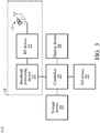
- Fig. 3 is a block diagram illustrating the UE 110 according to an embodiment of the application.
- the UE 110 includes a wireless transceiver 10, a controller 20, a storage device 30, a display device 40, and an Input/Output (I/O) device 50.
- I/O Input/Output
- the wireless transceiver 10 is configured to perform wireless transmission and reception to and from the RAN 121.
- the wireless transceiver 10 includes a Radio Frequency (RF) device 11, a baseband processing device 12, and antenna(s) 13, wherein the antenna(s) 13 may include one or more antennas for beamforming.
- the baseband processing device 12 is configured to perform baseband signal processing and control the communications between subscriber identity card(s) (not shown) and the RF device 11.
- the baseband processing device 12 may contain multiple hardware components to perform the baseband signal processing, including Analog-to-Digital Conversion (ADC)/Digital-to-Analog Conversion (DAC), gain adjusting, modulation/demodulation, encoding/decoding, and so on.
- ADC Analog-to-Digital Conversion
- DAC Digital-to-Analog Conversion
- the RF device 11 may receive RF wireless signals via the antenna(s) 13, convert the received RF wireless signals to baseband signals, which are processed by the baseband processing device 12, or receive baseband signals from the baseband processing device 12 and convert the received baseband signals to RF wireless signals, which are later transmitted via the antenna(s) 13.
- the RF device 11 may also contain multiple hardware devices to perform radio frequency conversion.
- the RF device 11 may comprise a mixer to multiply the baseband signals with a carrier oscillated in the radio frequency of the supported wireless technologies, wherein the radio frequency may be any radio frequency (e.g., 30GHz ⁇ 300GHz for mmWave) utilized in the 5G NR technology, or another radio frequency, depending on the wireless technology in use.
- beamforming is a signal processing technique used in the antenna array 13 or implemented by the baseband processing device 12 or by a combination of the above two for directional signal transmission/reception.
- a beam is be formed by combining elements in a phased array of antennas in such a way that signals at particular angles experience constructive interference while others experience destructive interference.
- Different beams are formed simultaneously using multiple arrays of antennas. The number of simultaneous beams in the time/frequency domain depends on the number of antenna array elements and the radio frequency being utilized.
- the controller 20 may be a general-purpose processor, a Micro Control Unit (MCU), an application processor, a Digital Signal Processor (DSP), Application Processor (AP), or the like, which includes various circuits for providing the functions of data processing and computing, controlling the wireless transceiver 10 for wireless communications with the RAN 121, storing and retrieving data (e.g., program code) to and from the storage device 30, sending a series of frame data (e.g. representing text messages, graphics, images, etc.) to the display device 40, and receiving signals from the I/O device 50.
- the controller 20 coordinates the aforementioned operations of the wireless transceiver 10, the storage device 30, the display device 40, and the I/O device 50 for performing the beam sweeping method of the present application.
- controller 20 may be incorporated into the baseband processing device 12, to serve as a baseband processor.
- the storage device 30 is a non-transitory machine-readable storage medium, including a memory, such as a FLASH memory or a Non-Volatile Random Access Memory (NVRAM), or a magnetic storage device, such as a hard disk or a magnetic tape, or an optical disc, or any combination thereof for storing instructions and/or program code of applications, communication protocols, and/or the beam sweeping method of the present application.
- a memory such as a FLASH memory or a Non-Volatile Random Access Memory (NVRAM)
- NVRAM Non-Volatile Random Access Memory
- magnetic storage device such as a hard disk or a magnetic tape, or an optical disc, or any combination thereof for storing instructions and/or program code of applications, communication protocols, and/or the beam sweeping method of the present application.
- the display device 40 may be a Liquid-Crystal Display (LCD), Light-Emitting Diode (LED) display, or Electronic Paper Display (EPD), etc., for providing a display function.
- the display device 40 may further include one or more touch sensors disposed thereon or thereunder for sensing touches, contacts, or approximations of objects, such as fingers or styluses.
- the I/O device 50 may include one or more buttons, a keyboard, a mouse, a touch pad, a video camera, a microphone, and/or a speaker, etc., to serve as the Man-Machine Interface (MMI) for interaction with users.
- MMI Man-Machine Interface
- the UE 110 may include more components, such as a power supply, or a Global Positioning System (GPS) device, wherein the power supply may be a mobile/replaceable battery providing power to all the other components of the UE 110, and the GPS device may provide the location information of the UE 110 for use of some location-based services or applications.
- a power supply may be a mobile/replaceable battery providing power to all the other components of the UE 110
- GPS device may provide the location information of the UE 110 for use of some location-based services or applications.
- Fig. 4 is a block diagram illustrating a cellular station according to an embodiment of the application.
- the cellular station may be a 5G cellular station, such as a gNB or TRP.
- the cellular station includes a wireless transceiver 60, a controller 70, a storage device 80, and a wired interface 90.
- the wireless transceiver 60 is configured to perform wireless transmission and reception to and from the UE 110.
- the wireless transceiver 60 includes an RF device 61, a baseband processing device 62, and antenna(s) 63, wherein the antenna(s) 63 may include one or more antennas for beamforming.
- the functions of the RF device 61, the baseband processing device 62, and the antenna(s) 63 are similar to those of the RF device 11, the baseband processing device 12, and the antenna(s) 13 as described in the embodiment of Fig. 3 , and thus, the detailed description is not repeated herein for brevity.
- the controller 70 may be a general-purpose processor, an MCU, an application processor, a DSP, an AP, or the like, which includes various circuits for providing the functions of data processing and computing, controlling the wireless transceiver 60 for wireless communications with the UE 110, storing and retrieving data (e.g., program code) to and from the storage device 80, and sending/receiving messages to/from other network entities (e.g., other cellular stations in the RAN 121 or other network entities in the NG-CN 122) through the wired interface 90.
- the controller 70 coordinates the aforementioned operations of the wireless transceiver 60, the storage device 80, and the wired interface 90 to perform the beam sweeping method of the present application.
- controller 70 may be incorporated into the baseband processing device 62, to serve as a baseband processor.
- the circuits of the controllers 20 and 70 will typically include transistors that are configured in such a way as to control the operation of the circuits in accordance with the functions and operations described herein.
- the specific structure or interconnections of the transistors will typically be determined by a compiler, such as a Register Transfer Language (RTL) compiler.
- RTL compilers may be operated by a processor upon scripts that closely resemble assembly language code, to compile the script into a form that is used for the layout or fabrication of the ultimate circuitry. Indeed, RTL is well known for its role and use in the facilitation of the design process of electronic and digital systems.
- the storage device 80 may be a memory, such as a FLASH memory or an NVRAM, or a magnetic storage device, such as a hard disk or a magnetic tape, or an optical disc, or any combination thereof for storing instructions and/or program code of applications, communication protocols, and/or the beam sweeping method of the present application.
- a memory such as a FLASH memory or an NVRAM
- a magnetic storage device such as a hard disk or a magnetic tape, or an optical disc, or any combination thereof for storing instructions and/or program code of applications, communication protocols, and/or the beam sweeping method of the present application.
- the wired interface 90 is responsible for providing wired communications with other network entities, such as other cellular stations in the RAN 121, or other network entities in the NG-CN 122.
- the wired interface 90 may include a cable modem, an Asymmetric Digital Subscriber Line (ADSL) modem, a Fiber-Optic Modem (FOM), and/or an Ethernet network interface.
- ADSL Asymmetric Digital Subscriber Line
- FOM Fiber-Optic Modem
- the cellular station may further include other functional devices, such as a display device (e.g., LCD, LED display, or EPD, etc.), an I/O device (e.g., button, keyboard, mouse, touch pad, video camera, microphone, speaker, etc.), and/or a power supply, etc.
- a display device e.g., LCD, LED display, or EPD, etc.
- I/O device e.g., button, keyboard, mouse, touch pad, video camera, microphone, speaker, etc.
- a power supply e.g., a power supply, etc.
- Fig. 5 is a schematic diagram illustrating a directional sequence of beams according to an embodiment of the application.
- there are 5 beams in the sequence which are denoted with numbers from 0 to 4 and are generated in sequence at different times.
- beam 0 is generated in the first time interval
- beam 1 is generated in the second time interval, and so on.
- all of the beams are generated with the same beam width, but the directions of the beams generated later in time are moving counterclockwise.
- beam sweeping is performed in the order of a directional sequence (i.e., beam 0 is swept first, and then beam 1, beam 2, beam 3, and beam 4 in sequence).
- Fig. 6 is a flow chart illustrating the beam sweeping method according to an embodiment of the application.
- the beam sweeping method may be applied to a wireless communication device, such as the UE 110 or a 5G cellular station or a Wi-Fi router, for transmission or reception operation.
- the wireless communication device performs wireless transmission or reception by sweeping beams in a non-sequential order (step S610), and the method ends.
- the beams are generated in different time intervals, e.g., different RACH occasions allocated in the time domain, and the non-sequential order indicates that some or all of the beams are not followed by their neighboring beams.
- the beams are swept in a beam-interleaving manner in the present application, so that inter-OFDM-symbol interference is further mitigated.
- the wireless communication device may determine whether the interference at the boundary between the current beam and a neighboring beam of the current beam is greater than a predetermined threshold, and if so, a non-neighboring beam may be preferably selected as the next beam. Otherwise, either the neighboring beam or a non-neighboring beam may be selected as the next beam.
- the wireless communication device may calculate the interference at the boundaries between the current beam and each one of the rest beams, respectively, and select one of the rest beams, which has the smallest interference, as the next beam.
- the wireless transmission in step S610 may refer to a UE transmitting multiple Physical Random Access Channel (PRACH) signals in different time intervals (e.g., consecutive time slots) using different beams in the non-sequential order.
- PRACH Physical Random Access Channel
- the wireless transmission in step S610 may refer to a UE transmitting multiple Sounding Reference Signals (SRS) in different time intervals (e.g., consecutive time slots) using different beams in the non-sequential order.
- SRS Sounding Reference Signals
- the wireless transmission in step S610 may refer to a 5G cellular station, such as a gNB or TRP, transmitting Synchronization Signal Blocks (SSBs) and Physical Broadcast Channel (PBCH) information in different time intervals (e.g., consecutive time slots) using different beams in the non-sequential order.
- a 5G cellular station such as a gNB or TRP
- SSBs Synchronization Signal Blocks
- PBCH Physical Broadcast Channel
- the wireless transmission in step S610 may refer to a 5G cellular station, such as a gNB or TRP, transmitting Channel State Information Reference Signals (CSI-RS) in different time intervals (e.g., consecutive time slots) using different beams in the non-sequential order.
- CSI-RS Channel State Information Reference Signals
- the wireless reception in step S610 may refer to a 5G cellular station, such as a gNB or TRP, receiving multiple PRACH signals in different time intervals (e.g., consecutive time slots) using different beams in the non-sequential order.
- a 5G cellular station such as a gNB or TRP
- the wireless reception in step S610 may refer to a 5G cellular station, such as a gNB or TRP, receiving multiple Physical Uplink Shared Channel (PUSCH) signals in different time intervals (e.g., consecutive time slots) using different beams in the non-sequential order.
- PUSCH Physical Uplink Shared Channel
- the wireless reception in step S610 may refer to a 5G cellular station, such as a gNB or TRP, receiving multiple Physical Uplink Control Channel (PUCCH) signals in different time intervals (e.g., consecutive time slots) using different beams in the non-sequential order.
- a 5G cellular station such as a gNB or TRP
- PUCCH Physical Uplink Control Channel
- the wireless reception in step S610 may refer to a 5G cellular station, such as a gNB or TRP, receiving different kinds of signals (e.g., including at least two of a PRACH signal, an SRS, a PUSCH signal, and a PUCCH signal) in different time intervals (e.g., consecutive time slots) using different beams in the non-sequential order.
- a 5G cellular station such as a gNB or TRP
- different kinds of signals e.g., including at least two of a PRACH signal, an SRS, a PUSCH signal, and a PUCCH signal
- time intervals e.g., consecutive time slots
- the wireless reception in step S610 may refer to a wireless communication device transmitting or receiving signals by using different beams in the non-sequential order for each symbol time intervals (e.g., each time the wireless communication device transmits or receives a symbol, the wireless communication device uses different beams, and the beams are switched in the non-sequential order).
- Fig. 7 is a block diagram illustrating beam sweeping in a non-sequential order according to an embodiment of the application.
- a sequence of 5 beams (denoted with numbers from 0 to 4) are generated in different time intervals for wireless transmission or reception.
- beam 0 is generated and swept.
- beam 2 is generated and swept.
- beam 4 is generated and swept.
- beam 1 is generated and swept.
- beam 3 is generated and swept.
- beam sweeping is performed in a non-sequential order, i.e., in a beam-interleaving manner.
- a non-sequential order i.e., in a beam-interleaving manner.
- Fig. 8 is a block diagram illustrating beam sweeping in a non-sequential order according to another embodiment of the application.
- a sequence of 5 beams (denoted with numbers from 0 to 4) are generated in different time intervals for wireless transmission or reception.
- beam 0 is generated and swept.
- beam 2 is generated and swept.
- beam 4 is generated and swept.
- beam 3 (i.e., a neighboring beam of the preceding beam) is generated and swept.
- beam 1 is generated and swept.
- beam sweeping is performed in a non-sequential order, i.e., in a beam-interleaving manner.
- a non-sequential order i.e., in a beam-interleaving manner.
- Fig. 9 is a block diagram illustrating beam sweeping in a non-sequential order according to another embodiment of the application.
- a sequence of 4 beams (denoted with numbers from 0 to 3) are generated in different time intervals for wireless transmission or reception.
- beam 0 is generated and swept.
- beam 2 is generated and swept.
- beam 1 i.e., a neighboring beam of the preceding beam
- beam 3 is generated and swept.
- beam sweeping is performed in a non-sequential order, i.e., in a beam-interleaving manner.
- a non-sequential order i.e., in a beam-interleaving manner.
- the present application advantageously mitigates the interferences at the boundaries of beam switching, by configuring the beams to be swept in a non-sequential order.
- the non-sequential order indicates that some or all of the beams are not followed by their neighboring beams.
- Figs. 7 to 9 examples of the non-sequential order are provided in Figs. 7 to 9 , it should be understood that the examples are for illustrative purposes only and are not intended to limit the scope of the application.
- the beam sweeping may be performed according the directional sequence as shown in Fig. 5 . That is, the beam sweeping may be performed by switching between the different embodiments depicted in Figs. 5 and 7 to 9 .
Landscapes
- Engineering & Computer Science (AREA)
- Computer Networks & Wireless Communication (AREA)
- Signal Processing (AREA)
- Mobile Radio Communication Systems (AREA)
Abstract
Description
- This Application claims priority of
U.S. Provisional Application No. 62/458,048, filed on February 13, 2017 - The application generally relates to wireless communications, and more particularly, to apparatuses and methods for beam sweeping in a wireless communication system (e.g., a fifth-generation (5G) New Radio (NR) system or a Wi-Fi system).
- The fifth generation (5G) New Radio (NR) technology is an improvement upon the fourth generation (4G) Long Term Evolution (LTE) technology, which provides extreme data speeds and capacity, by utilizing higher and unlicensed spectrum bands (e.g., above 30 GHz, loosely known as millimeter Wave (mmWave)), for wireless broadband communications. Due to the huge path and penetration losses at millimeter wavelengths, a technique called "beamforming" is employed and it assumes an important role in establishing and maintaining a robust communication link.
- Beamforming generally requires one or more antenna arrays, each comprising a plurality of antennas. By appropriately setting antenna weights that define a contribution of each one of the antennas to a transmission or reception operation, it becomes possible to shape the sensitivity of the transmission/reception to a particularly high value in a specific beamformed direction. By applying different antenna weights, different beam patterns can be achieved, e.g., different directive beams can be sequentially employed.
- During a transmission (Tx) operation, beamforming may direct the signal towards a receiver of interest. Likewise, during a reception (Rx) operation, beamforming may provide a high sensitivity in receiving the signal originating from a sender of interest. Since the transmission power may be anisotropically focused, e.g., into a solid angle of interest, beamforming may provide better link budgets due to lower required Tx power and higher received signal power, when compared to a conventional practice which does not employ beamforming and relies on more or less isotropic transmission.
- However, such technique as mentioned above faces certain challenges. For example, in the initial access stage of wireless communications, multi-beam operations are often conducted to sweep over all beams to select suitable beam pairs for wireless transmission and reception. Typically, beam sweeping is performed by sequentially pointing directive beams in a sequential order to discover a transceiver of interest. Particularly, during the initial access stage in a 5G NR system, there are situations where consecutive Random Access Channel (RACH) occasions are allocated to a next generation Node-B (gNB) to perform beam sweeping for wireless reception.
Fig. 1 is a schematic diagram illustrating consecutive RACH occasions allocated to a gNB for Rx beam sweeping in a sequential order. As the 3rd Generation Partnership
Project (3GPP) has concluded that the ON-OFF transient period for a UE is 5 micro-seconds for carrier frequencies above 24 GHz. The 5 micro-seconds transient period of a UE may introduce significant interferences to the UEs attempting to access the gNB in the preceding and following RACH occasions, as shown inFig. 1 . - Therefore, it is desirable to have a more robust way of beam sweeping, which may mitigate the interferences at the boundaries of beam switching.
- In order to solve the aforementioned problem, the present application proposes wireless communication devices and beam sweeping methods, in which the beams are configured to be swept in a non-sequential order (e.g., in a beam-interleaving manner), so that inter-Orthogonal frequency-division multiplexing (OFDM)-symbol interferences may be efficiently reduced.
- In one aspect of the application, a wireless communication device comprising a controller and a non-transitory machine-readable storage medium operatively coupled to the controller is provided. The controller is configured to execute program code stored in the non-transitory machine-readable storage medium to perform operations comprising: transmitting or receiving wireless signals by sweeping beams in a non-sequential order.
- In another aspect of the application, a beam sweeping method, executed by a wireless communication device, is provided. The beam sweeping method comprises the steps of: transmitting or receiving wireless signals by sweeping beams in a non-sequential order.
- Other aspects and features of the present application will become apparent to those with ordinarily skill in the art upon review of the following descriptions of specific embodiments of the wireless communication devices and the beam sweeping methods.
- The application can be more fully understood by reading the subsequent detailed description and examples with references made to the accompanying drawings, wherein:
-
Fig. 1 is a schematic diagram illustrating consecutive RACH occasions allocated to a gNB for Rx beam sweeping in a sequential order; -
Fig. 2 is a block diagram of a wireless communication environment according to an embodiment of the application; -
Fig. 3 is a block diagram illustrating theUE 110 according to an embodiment of the application; -
Fig. 4 is a block diagram illustrating a cellular station according to an embodiment of the application; -
Fig. 5 is a schematic diagram illustrating a directional sequence of beams according to an embodiment of the application; -
Fig. 6 is a flow chart illustrating the beam sweeping method according to an embodiment of the application; -
Fig. 7 is a block diagram illustrating beam sweeping in a non-sequential order according to an embodiment of the application; -
Fig. 8 is a block diagram illustrating beam sweeping in a non-sequential order according to another embodiment of the application; and -
Fig. 9 is a block diagram illustrating beam sweeping in a non-sequential order according to another embodiment of the application. - The following description is made for the purpose of illustrating the general principles of the application and should not be taken in a limiting sense. It should be understood that the embodiments may be realized in software, hardware, firmware, or any combination thereof. The terms "comprises," "comprising," "includes" and/or "including," when used herein, specify the presence of stated features, integers, steps, operations, elements, and/or components, but do not preclude the presence or addition of one or more other features, integers, steps, operations, elements, components, and/or groups thereof.
-
Fig. 2 is a block diagram of a wireless communication environment according to an embodiment of the application. Thewireless communication environment 100 includes a User Equipment (UE) 110 and a5G NR network 120, wherein the UE 110 is wirelessly connected to the 5G NRnetwork 120 for obtaining mobile services. - The UE 110 may be a feature phone, a smartphone, a panel Personal Computer (PC), a laptop computer, or any wireless communication device supporting the wireless technology (i.e., the 5G NR technology) utilized by the
5G NR network 120 and/or the Wireless-Fidelity (Wi-Fi) technology. Particularly, the wireless communication device employs the beamforming technique for wireless transmission and/or reception. - The
5G NR network 120 includes a Radio Access Network (RAN) 121 and a Next Generation Core Network (NG-CN) 122. - The RAN 121 is responsible for processing radio signals, terminating radio protocols, and connecting the UE 110 with the NG-CN 122. The RAN 121 may include one or more gNBs which support high frequency bands (e.g., above 24GHz), and each gNB may further include one or more Transmission Reception Points (TRPs), wherein each gNB or TRP may be referred to as a 5G cellular station. Some gNB functionalities may be distributed across different TRPs, while others may be centralized, leaving the flexibility and scope for specific deployments to fulfill the requirements for specific use cases. Specifically, each gNB or TRP may employ the beamforming technique to generate one or more beams, each with a different beamformed direction, for wireless transmission and/or reception.
- The NG-CN 122 generally consists of various network functions, including Access and Mobility Function (AMF), Session Management Function (SMF), Policy Control Function (PCF), Application Function (AF), Authentication Server Function (AUSF), User Plane Function (UPF), and User Data Management (UDM), wherein each network function may be implemented as a network element on a dedicated hardware, or as a software instance running on a dedicated hardware, or as a virtualized function instantiated on an appropriate platform, e.g., a cloud infrastructure.
- The AMF provides UE-based authentication, authorization, mobility management, etc. The SMF is responsible for session management and allocates Internet Protocol (IP) addresses to UEs. It also selects and controls the UPF for data transfer. If a UE has multiple sessions, different SMFs may be allocated to each session to manage them individually and possibly provide different functionalities per session. The AF provides information on the packet flow to PCF responsible for policy control in order to support Quality of Service (QoS). Based on the information, the PCF determines policies about mobility and session management to make the AMF and the SMF operate properly. The AUSF stores data for authentication of UEs, while the UDM stores subscription data of UEs.
- It should be noted that the
5G NR network 120 depicted inFig. 2 is for illustrative purposes only and is not intended to limit the scope of the application. The invention could be applied to other wireless technologies. For example, the UE 110 may be a wireless communication device supporting Wi-Fi technology and may be wirelessly connected to a Wi-Fi network, which also supports the beamforming technique for wireless transmission and/or reception to/from the UE 110. -
Fig. 3 is a block diagram illustrating theUE 110 according to an embodiment of the application. TheUE 110 includes awireless transceiver 10, acontroller 20, astorage device 30, adisplay device 40, and an Input/Output (I/O)device 50. - The
wireless transceiver 10 is configured to perform wireless transmission and reception to and from theRAN 121. Specifically, thewireless transceiver 10 includes a Radio Frequency (RF)device 11, abaseband processing device 12, and antenna(s) 13, wherein the antenna(s) 13 may include one or more antennas for beamforming. Thebaseband processing device 12 is configured to perform baseband signal processing and control the communications between subscriber identity card(s) (not shown) and theRF device 11. Thebaseband processing device 12 may contain multiple hardware components to perform the baseband signal processing, including Analog-to-Digital Conversion (ADC)/Digital-to-Analog Conversion (DAC), gain adjusting, modulation/demodulation, encoding/decoding, and so on. TheRF device 11 may receive RF wireless signals via the antenna(s) 13, convert the received RF wireless signals to baseband signals, which are processed by thebaseband processing device 12, or receive baseband signals from thebaseband processing device 12 and convert the received baseband signals to RF wireless signals, which are later transmitted via the antenna(s) 13. TheRF device 11 may also contain multiple hardware devices to perform radio frequency conversion. For example, theRF device 11 may comprise a mixer to multiply the baseband signals with a carrier oscillated in the radio frequency of the supported wireless technologies, wherein the radio frequency may be any radio frequency (e.g., 30GHz∼300GHz for mmWave) utilized in the 5G NR technology, or another radio frequency, depending on the wireless technology in use. - To further clarify, beamforming is a signal processing technique used in the
antenna array 13 or implemented by thebaseband processing device 12 or by a combination of the above two for directional signal transmission/reception. In beamforming, a beam is be formed by combining elements in a phased array of antennas in such a way that signals at particular angles experience constructive interference while others experience destructive interference. Different beams are formed simultaneously using multiple arrays of antennas. The number of simultaneous beams in the time/frequency domain depends on the number of antenna array elements and the radio frequency being utilized. - The
controller 20 may be a general-purpose processor, a Micro Control Unit (MCU), an application processor, a Digital Signal Processor (DSP), Application Processor (AP), or the like, which includes various circuits for providing the functions of data processing and computing, controlling thewireless transceiver 10 for wireless communications with theRAN 121, storing and retrieving data (e.g., program code) to and from thestorage device 30, sending a series of frame data (e.g. representing text messages, graphics, images, etc.) to thedisplay device 40, and receiving signals from the I/O device 50. In particular, thecontroller 20 coordinates the aforementioned operations of thewireless transceiver 10, thestorage device 30, thedisplay device 40, and the I/O device 50 for performing the beam sweeping method of the present application. - In another embodiment, the
controller 20 may be incorporated into thebaseband processing device 12, to serve as a baseband processor. - The
storage device 30 is a non-transitory machine-readable storage medium, including a memory, such as a FLASH memory or a Non-Volatile Random Access Memory (NVRAM), or a magnetic storage device, such as a hard disk or a magnetic tape, or an optical disc, or any combination thereof for storing instructions and/or program code of applications, communication protocols, and/or the beam sweeping method of the present application. - The
display device 40 may be a Liquid-Crystal Display (LCD), Light-Emitting Diode (LED) display, or Electronic Paper Display (EPD), etc., for providing a display function. Alternatively, thedisplay device 40 may further include one or more touch sensors disposed thereon or thereunder for sensing touches, contacts, or approximations of objects, such as fingers or styluses. - The I/
O device 50 may include one or more buttons, a keyboard, a mouse, a touch pad, a video camera, a microphone, and/or a speaker, etc., to serve as the Man-Machine Interface (MMI) for interaction with users. - It should be understood that the components described in the embodiment of
Fig. 3 are for illustrative purposes only and are not intended to limit the scope of the application. For example, theUE 110 may include more components, such as a power supply, or a Global Positioning System (GPS) device, wherein the power supply may be a mobile/replaceable battery providing power to all the other components of theUE 110, and the GPS device may provide the location information of theUE 110 for use of some location-based services or applications. -
Fig. 4 is a block diagram illustrating a cellular station according to an embodiment of the application. The cellular station may be a 5G cellular station, such as a gNB or TRP. The cellular station includes awireless transceiver 60, acontroller 70, astorage device 80, and awired interface 90. - The
wireless transceiver 60 is configured to perform wireless transmission and reception to and from theUE 110. Specifically, thewireless transceiver 60 includes anRF device 61, abaseband processing device 62, and antenna(s) 63, wherein the antenna(s) 63 may include one or more antennas for beamforming. The functions of theRF device 61, thebaseband processing device 62, and the antenna(s) 63 are similar to those of theRF device 11, thebaseband processing device 12, and the antenna(s) 13 as described in the embodiment ofFig. 3 , and thus, the detailed description is not repeated herein for brevity. - The
controller 70 may be a general-purpose processor, an MCU, an application processor, a DSP, an AP, or the like, which includes various circuits for providing the functions of data processing and computing, controlling thewireless transceiver 60 for wireless communications with theUE 110, storing and retrieving data (e.g., program code) to and from thestorage device 80, and sending/receiving messages to/from other network entities (e.g., other cellular stations in theRAN 121 or other network entities in the NG-CN 122) through the wiredinterface 90. In particular, thecontroller 70 coordinates the aforementioned operations of thewireless transceiver 60, thestorage device 80, and thewired interface 90 to perform the beam sweeping method of the present application. - In another embodiment, the
controller 70 may be incorporated into thebaseband processing device 62, to serve as a baseband processor. - As will be appreciated by persons skilled in the art, the circuits of the
controllers - The
storage device 80 may be a memory, such as a FLASH memory or an NVRAM, or a magnetic storage device, such as a hard disk or a magnetic tape, or an optical disc, or any combination thereof for storing instructions and/or program code of applications, communication protocols, and/or the beam sweeping method of the present application. - The
wired interface 90 is responsible for providing wired communications with other network entities, such as other cellular stations in theRAN 121, or other network entities in the NG-CN 122. Thewired interface 90 may include a cable modem, an Asymmetric Digital Subscriber Line (ADSL) modem, a Fiber-Optic Modem (FOM), and/or an Ethernet network interface. - It should be understood that the components described in the embodiment of
Fig. 4 are for illustrative purposes only and are not intended to limit the scope of the application. For example, the cellular station may further include other functional devices, such as a display device (e.g., LCD, LED display, or EPD, etc.), an I/O device (e.g., button, keyboard, mouse, touch pad, video camera, microphone, speaker, etc.), and/or a power supply, etc. -
Fig. 5 is a schematic diagram illustrating a directional sequence of beams according to an embodiment of the application. As shown inFig. 5 , there are 5 beams in the sequence, which are denoted with numbers from 0 to 4 and are generated in sequence at different times. For example,beam 0 is generated in the first time interval, and beam 1 is generated in the second time interval, and so on. Particularly, all of the beams are generated with the same beam width, but the directions of the beams generated later in time are moving counterclockwise. Please note that, conventionally, beam sweeping is performed in the order of a directional sequence (i.e.,beam 0 is swept first, and then beam 1, beam 2, beam 3, andbeam 4 in sequence). -
Fig. 6 is a flow chart illustrating the beam sweeping method according to an embodiment of the application. In this embodiment, the beam sweeping method may be applied to a wireless communication device, such as theUE 110 or a 5G cellular station or a Wi-Fi router, for transmission or reception operation. To begin with, the wireless communication device performs wireless transmission or reception by sweeping beams in a non-sequential order (step S610), and the method ends. Specifically, the beams are generated in different time intervals, e.g., different RACH occasions allocated in the time domain, and the non-sequential order indicates that some or all of the beams are not followed by their neighboring beams. In other words, unlike the conventional practice, the beams are swept in a beam-interleaving manner in the present application, so that inter-OFDM-symbol interference is further mitigated. - During the beam sweeping process, the beams are swept according to the interference at the boundary between a current beam and another beam. In one embodiment, the wireless communication device may determine whether the interference at the boundary between the current beam and a neighboring beam of the current beam is greater than a predetermined threshold, and if so, a non-neighboring beam may be preferably selected as the next beam. Otherwise, either the neighboring beam or a non-neighboring beam may be selected as the next beam. In another embodiment, the wireless communication device may calculate the interference at the boundaries between the current beam and each one of the rest beams, respectively, and select one of the rest beams, which has the smallest interference, as the next beam.
- In one embodiment, the wireless transmission in step S610 may refer to a UE transmitting multiple Physical Random Access Channel (PRACH) signals in different time intervals (e.g., consecutive time slots) using different beams in the non-sequential order.
- In another embodiment, the wireless transmission in step S610 may refer to a UE transmitting multiple Sounding Reference Signals (SRS) in different time intervals (e.g., consecutive time slots) using different beams in the non-sequential order.
- In another embodiment, the wireless transmission in step S610 may refer to a 5G cellular station, such as a gNB or TRP, transmitting Synchronization Signal Blocks (SSBs) and Physical Broadcast Channel (PBCH) information in different time intervals (e.g., consecutive time slots) using different beams in the non-sequential order.
- In another embodiment, the wireless transmission in step S610 may refer to a 5G cellular station, such as a gNB or TRP, transmitting Channel State Information Reference Signals (CSI-RS) in different time intervals (e.g., consecutive time slots) using different beams in the non-sequential order.
- In one embodiment, the wireless reception in step S610 may refer to a 5G cellular station, such as a gNB or TRP, receiving multiple PRACH signals in different time intervals (e.g., consecutive time slots) using different beams in the non-sequential order.
- In another embodiment, the wireless reception in step S610 may refer to a 5G cellular station, such as a gNB or TRP, receiving multiple Physical Uplink Shared Channel (PUSCH) signals in different time intervals (e.g., consecutive time slots) using different beams in the non-sequential order.
- In another embodiment, the wireless reception in step S610 may refer to a 5G cellular station, such as a gNB or TRP, receiving multiple Physical Uplink Control Channel (PUCCH) signals in different time intervals (e.g., consecutive time slots) using different beams in the non-sequential order.
- In another embodiment, the wireless reception in step S610 may refer to a 5G cellular station, such as a gNB or TRP, receiving different kinds of signals (e.g., including at least two of a PRACH signal, an SRS, a PUSCH signal, and a PUCCH signal) in different time intervals (e.g., consecutive time slots) using different beams in the non-sequential order. In another embodiment, the wireless reception in step S610 may refer to a wireless communication device transmitting or receiving signals by using different beams in the non-sequential order for each symbol time intervals (e.g., each time the wireless communication device transmits or receives a symbol, the wireless communication device uses different beams, and the beams are switched in the non-sequential order).
-
Fig. 7 is a block diagram illustrating beam sweeping in a non-sequential order according to an embodiment of the application. In this embodiment, a sequence of 5 beams (denoted with numbers from 0 to 4) are generated in different time intervals for wireless transmission or reception. - As shown in
Fig. 7 , in the first time interval,beam 0 is generated and swept. In the second time interval, beam 2 is generated and swept. In the third time interval,beam 4 is generated and swept. In the fourth time interval, beam 1 is generated and swept. Finally, in the fifth time interval, beam 3 is generated and swept. - Please note that, despite the directional sequence of the beams, beam sweeping is performed in a non-sequential order, i.e., in a beam-interleaving manner. Through the particular arrangement of the non-sequential order as shown in
Fig. 7 , all of the beams are not followed by their neighboring beams. -
Fig. 8 is a block diagram illustrating beam sweeping in a non-sequential order according to another embodiment of the application. In this embodiment, a sequence of 5 beams (denoted with numbers from 0 to 4) are generated in different time intervals for wireless transmission or reception. - As shown in
Fig. 8 , in the first time interval,beam 0 is generated and swept. In the second time interval, beam 2 is generated and swept. In the third time interval,beam 4 is generated and swept. In the fourth time interval, beam 3 (i.e., a neighboring beam of the preceding beam) is generated and swept. Finally, in the fifth time interval, beam 1 is generated and swept. - Please note that, despite the directional sequence of the beams, beam sweeping is performed in a non-sequential order, i.e., in a beam-interleaving manner. Through the particular arrangement of the non-sequential order as shown in
Fig. 8 , some of the beams are not followed by their neighboring beams. -
Fig. 9 is a block diagram illustrating beam sweeping in a non-sequential order according to another embodiment of the application. In this embodiment, a sequence of 4 beams (denoted with numbers from 0 to 3) are generated in different time intervals for wireless transmission or reception. - As shown in
Fig. 9 , in the first time interval,beam 0 is generated and swept. In the second time interval, beam 2 is generated and swept. In the third time interval, beam 1 (i.e., a neighboring beam of the preceding beam) is generated and swept. Finally, in the fourth time interval, beam 3 is generated and swept. - Please note that, despite the directional sequence of the beams, beam sweeping is performed in a non-sequential order, i.e., in a beam-interleaving manner. Through the particular arrangement of the non-sequential order as shown in
Fig. 9 , some of the beams are not followed by their neighboring beams. - In view of the forgoing embodiments, it will be appreciated that the present application advantageously mitigates the interferences at the boundaries of beam switching, by configuring the beams to be swept in a non-sequential order. Specifically, the non-sequential order indicates that some or all of the beams are not followed by their neighboring beams. Although examples of the non-sequential order are provided in
Figs. 7 to 9 , it should be understood that the examples are for illustrative purposes only and are not intended to limit the scope of the application. For example, the beam sweeping may be performed according the directional sequence as shown inFig. 5 . That is, the beam sweeping may be performed by switching between the different embodiments depicted inFigs. 5 and7 to 9 . - While the application has been described by way of example and in terms of preferred embodiment, it should be understood that the application is not limited thereto. Those who are skilled in this technology can still make various alterations and modifications without departing from the scope and spirit of this application. Therefore, the scope of the present application shall be defined and protected by the following claims and their equivalents.
- Use of ordinal terms such as "first", "second", etc., in the claims to modify a claim element does not by itself connote any priority, precedence, or order of one claim element over another or the temporal order in which acts of a method are performed, but are used merely as labels to distinguish one claim element having a certain name from another element having the same name (but for use of the ordinal term) to distinguish the claim elements.
Claims (12)
- A wireless communication device, comprising:a controller; anda non-transitory machine-readable storage medium,operatively coupled to the controller;wherein the controller is configured to execute program code stored in the non-transitory machine-readable storage medium to perform operations comprising:transmitting or receiving wireless signals by sweeping beams in a non-sequential order.
- The wireless communication device of claim 1, wherein the non-sequential order indicates that some or all of the beams are not followed by their neighboring beams.
- The wireless communication device of claim 1, wherein the sweeping of the beams is performed according to interference at a boundary between a current beam and another beam.
- The wireless communication device of claim 1, wherein the wireless signals are transmitted or received by sweeping the beams in the non-sequential order to mitigate inter-Orthogonal frequency-division multiplexing (OFDM)-symbol interferences.
- The wireless communication device of claim 1, wherein the transmitted wireless signals comprise multiple Physical Random Access Channel (PRACH) signals or Sounding Reference Signals (SRS) in different time intervals, when the wireless communication device is configured as a fifth-generation (5G) User Equipment (UE); or the transmitted wireless signals comprise Synchronization Signal Blocks (SSBs) and Physical Broadcast Channel (PBCH) information in different time intervals, or comprise multiple Channel State Information Reference Signals (CSI-RS) in different time intervals, when the wireless communication device is configured as a 5G cellular station.
- The wireless communication device of claim 1, wherein the received wireless signals comprise multiple PRACH signals, multiple Physical Uplink Shared Channel (PUSCH) signals, multiple Physical Uplink Control Channel (PUCCH) signals, or at least two of a PRACH signal, an SRS, a PUCCH signal, and a PUSCH signal, in different time intervals, when the wireless communication device is configured as a 5G cellular station.
- A beam sweeping method, executed by a wireless communication device, comprising:transmitting or receiving wireless signals by sweeping the beams in a non-sequential order.
- The beam sweeping method of claim 7 wherein the non-sequential order indicates that some or all of the beams are not followed by their neighboring beams.
- The beam sweeping method of claim 7, wherein the sweeping of the beams is performed according to interference at a boundary between a current beam and another beam.
- The beam sweeping method of claim 7, wherein the wireless signals are transmitted or received by sweeping the beams in the non-sequential order to mitigate inter-OFDM-symbol interferences.
- The beam sweeping method of claim 7, wherein the transmitted wireless signals comprise multiple PRACH signals or SRS in different time intervals, when the wireless communication device is configured as a 5G UE; or the transmitted wireless signals comprise SSBs and PBCH information in different time intervals, or comprise multiple CSI-RS in different time intervals, when the wireless communication device is configured as a 5G cellular station.
- The beam sweeping method of claim 7, wherein the received wireless signals comprise multiple PRACH signals, multiple PUSCH signals, multiple PUCCH signals, or at least two of a PRACH signal, an SRS, a PUCCH signal, and a PUSCH signal, in different time intervals, when the wireless communication device is configured as a 5G cellular station.
Applications Claiming Priority (2)
| Application Number | Priority Date | Filing Date | Title |
|---|---|---|---|
| US201762458048P | 2017-02-13 | 2017-02-13 | |
| US15/893,885 US10666341B2 (en) | 2017-02-13 | 2018-02-12 | Apparatuses and methods for beam sweeping in a wireless communication system |
Publications (2)
| Publication Number | Publication Date |
|---|---|
| EP3361647A1 true EP3361647A1 (en) | 2018-08-15 |
| EP3361647B1 EP3361647B1 (en) | 2020-01-08 |
Family
ID=61223763
Family Applications (1)
| Application Number | Title | Priority Date | Filing Date |
|---|---|---|---|
| EP18156574.8A Active EP3361647B1 (en) | 2017-02-13 | 2018-02-13 | Apparatuses and methods for beam sweeping in a wireless communication system |
Country Status (2)
| Country | Link |
|---|---|
| US (1) | US10666341B2 (en) |
| EP (1) | EP3361647B1 (en) |
Cited By (1)
| Publication number | Priority date | Publication date | Assignee | Title |
|---|---|---|---|---|
| US12449499B2 (en) | 2023-06-16 | 2025-10-21 | Rockwell Collins, Inc. | System and method for efficient directional discovery of communications terminals via beam interleaving |
Families Citing this family (4)
| Publication number | Priority date | Publication date | Assignee | Title |
|---|---|---|---|---|
| US11102738B2 (en) * | 2018-04-06 | 2021-08-24 | Apple Inc. | Synchronization signal design for unlicensed spectrum access using cellular communications |
| CN111726207A (en) | 2019-03-18 | 2020-09-29 | 成都华为技术有限公司 | Method and apparatus for randomization of interference |
| US10492130B1 (en) * | 2019-03-20 | 2019-11-26 | Qualcomm Incorporated | Search scheduling for wireless communications |
| IL274510A (en) * | 2020-05-06 | 2021-12-01 | Qualcomm Inc | Synchronization signal block (ssb) overloading |
Citations (4)
| Publication number | Priority date | Publication date | Assignee | Title |
|---|---|---|---|---|
| US20040002363A1 (en) * | 2002-06-28 | 2004-01-01 | Interdigital Technology Corporation | System for efficiently providing coverage of a sectorized cell for common and dedicated channels utilizing beam forming and sweeping |
| US20110038308A1 (en) * | 2007-10-04 | 2011-02-17 | Yi Song | Forming spatial beams within a cell segment |
| WO2016043502A1 (en) * | 2014-09-15 | 2016-03-24 | 삼성전자 주식회사 | Channel accessing method and device in wireless communication system |
| US20160248451A1 (en) * | 2015-02-23 | 2016-08-25 | Qualcomm Incorporated | Transceiver configuration for millimeter wave wireless communications |
Family Cites Families (6)
| Publication number | Priority date | Publication date | Assignee | Title |
|---|---|---|---|---|
| US9008222B2 (en) * | 2012-08-14 | 2015-04-14 | Samsung Electronics Co., Ltd. | Multi-user and single user MIMO for communication systems using hybrid beam forming |
| US9497047B2 (en) * | 2013-07-02 | 2016-11-15 | Samsung Electronics Co., Ltd. | Methods and apparatus for sounding channel operation in millimeter wave communication systems |
| KR102180959B1 (en) * | 2013-12-09 | 2020-11-19 | 삼성전자주식회사 | Adaptive beam sweeping coordination method and apparatus in a wireless communication system |
| CN107852705B (en) | 2015-08-20 | 2022-05-06 | 苹果公司 | transmit beamforming |
| US10575338B2 (en) * | 2016-02-04 | 2020-02-25 | Samsung Electronics Co., Ltd. | Method and apparatus for UE signal transmission in 5G cellular communications |
| US10499416B2 (en) * | 2017-01-10 | 2019-12-03 | Qualcomm Incorporated | Downlink channel rate matching of synchronization signal block transmissions in a new radio wireless communication system |
-
2018
- 2018-02-12 US US15/893,885 patent/US10666341B2/en active Active
- 2018-02-13 EP EP18156574.8A patent/EP3361647B1/en active Active
Patent Citations (5)
| Publication number | Priority date | Publication date | Assignee | Title |
|---|---|---|---|---|
| US20040002363A1 (en) * | 2002-06-28 | 2004-01-01 | Interdigital Technology Corporation | System for efficiently providing coverage of a sectorized cell for common and dedicated channels utilizing beam forming and sweeping |
| US20110038308A1 (en) * | 2007-10-04 | 2011-02-17 | Yi Song | Forming spatial beams within a cell segment |
| WO2016043502A1 (en) * | 2014-09-15 | 2016-03-24 | 삼성전자 주식회사 | Channel accessing method and device in wireless communication system |
| US20170257780A1 (en) * | 2014-09-15 | 2017-09-07 | Samsung Electronics Co., Ltd. | Channel accessing method and device in wireless communication system |
| US20160248451A1 (en) * | 2015-02-23 | 2016-08-25 | Qualcomm Incorporated | Transceiver configuration for millimeter wave wireless communications |
Non-Patent Citations (2)
| Title |
|---|
| INTERDIGITAL COMMUNICATIONS: "Considerations for DL Broadcast Channel", vol. RAN WG1, no. Lisbon, Portugal; 20161010 - 20161014, 9 October 2016 (2016-10-09), XP051150368, Retrieved from the Internet <URL:http://www.3gpp.org/ftp/Meetings_3GPP_SYNC/RAN1/Docs/> [retrieved on 20161009] * |
| LG ELECTRONICS INTEL MEDIATEK [ERICSSON] [ZTE] [NOKIA]: "WF on SRS for UL beam management", vol. RAN WG1, no. Spokane, USA; 20170116 - 20170120, 19 January 2017 (2017-01-19), XP051222376, Retrieved from the Internet <URL:http://www.3gpp.org/ftp/tsg_ran/WG1_RL1/TSGR1_AH/NR_AH_1701/Docs/> [retrieved on 20170119] * |
Cited By (1)
| Publication number | Priority date | Publication date | Assignee | Title |
|---|---|---|---|---|
| US12449499B2 (en) | 2023-06-16 | 2025-10-21 | Rockwell Collins, Inc. | System and method for efficient directional discovery of communications terminals via beam interleaving |
Also Published As
| Publication number | Publication date |
|---|---|
| US10666341B2 (en) | 2020-05-26 |
| US20180234156A1 (en) | 2018-08-16 |
| EP3361647B1 (en) | 2020-01-08 |
Similar Documents
| Publication | Publication Date | Title |
|---|---|---|
| EP3610686B1 (en) | Apparatuses and methods for physical random access channel (prach) retransmission | |
| US11290894B2 (en) | Apparatuses and methods for beam identification through the physical random access channel (PRACH) and efficient PRACH resource utilization | |
| WO2018206011A1 (en) | Apparatuses and methods for beam selection during a physical random access channel (prach) transmission or retransmission | |
| US10887920B2 (en) | Apparatuses and methods for Bandwidth Part (BWP) selection for a random access procedure | |
| US10666341B2 (en) | Apparatuses and methods for beam sweeping in a wireless communication system | |
| CN108476499B (en) | Guard periods between subframe portions of the same link direction in a wireless network | |
| JP2019509660A5 (en) | ||
| US20210211892A1 (en) | Dynamic configuration and use of wireless base stations in a network | |
| CN110166094B (en) | Wireless communication device and beam scanning method | |
| CN111586753B (en) | Wireless communication devices and methods for multipath communication using multiple wireless technologies | |
| CN116208212A (en) | Beam alignment method and base station | |
| BR112019023397B1 (en) | USER EQUIPMENT AND METHOD FOR A PHYSICAL RANDOM ACCESS CHANNEL (PRACH) RETRANSMISSION |
Legal Events
| Date | Code | Title | Description |
|---|---|---|---|
| PUAI | Public reference made under article 153(3) epc to a published international application that has entered the european phase |
Free format text: ORIGINAL CODE: 0009012 |
|
| STAA | Information on the status of an ep patent application or granted ep patent |
Free format text: STATUS: THE APPLICATION HAS BEEN PUBLISHED |
|
| AK | Designated contracting states |
Kind code of ref document: A1 Designated state(s): AL AT BE BG CH CY CZ DE DK EE ES FI FR GB GR HR HU IE IS IT LI LT LU LV MC MK MT NL NO PL PT RO RS SE SI SK SM TR |
|
| AX | Request for extension of the european patent |
Extension state: BA ME |
|
| STAA | Information on the status of an ep patent application or granted ep patent |
Free format text: STATUS: REQUEST FOR EXAMINATION WAS MADE |
|
| 17P | Request for examination filed |
Effective date: 20190212 |
|
| RBV | Designated contracting states (corrected) |
Designated state(s): AL AT BE BG CH CY CZ DE DK EE ES FI FR GB GR HR HU IE IS IT LI LT LU LV MC MK MT NL NO PL PT RO RS SE SI SK SM TR |
|
| GRAP | Despatch of communication of intention to grant a patent |
Free format text: ORIGINAL CODE: EPIDOSNIGR1 |
|
| STAA | Information on the status of an ep patent application or granted ep patent |
Free format text: STATUS: GRANT OF PATENT IS INTENDED |
|
| RIC1 | Information provided on ipc code assigned before grant |
Ipc: H04B 7/08 20060101ALI20191008BHEP Ipc: H04B 7/0404 20170101ALI20191008BHEP Ipc: H04B 7/0408 20170101AFI20191008BHEP Ipc: H04B 7/06 20060101ALI20191008BHEP |
|
| INTG | Intention to grant announced |
Effective date: 20191029 |
|
| GRAS | Grant fee paid |
Free format text: ORIGINAL CODE: EPIDOSNIGR3 |
|
| GRAA | (expected) grant |
Free format text: ORIGINAL CODE: 0009210 |
|
| STAA | Information on the status of an ep patent application or granted ep patent |
Free format text: STATUS: THE PATENT HAS BEEN GRANTED |
|
| AK | Designated contracting states |
Kind code of ref document: B1 Designated state(s): AL AT BE BG CH CY CZ DE DK EE ES FI FR GB GR HR HU IE IS IT LI LT LU LV MC MK MT NL NO PL PT RO RS SE SI SK SM TR |
|
| REG | Reference to a national code |
Ref country code: GB Ref legal event code: FG4D |
|
| REG | Reference to a national code |
Ref country code: CH Ref legal event code: EP |
|
| REG | Reference to a national code |
Ref country code: DE Ref legal event code: R096 Ref document number: 602018001931 Country of ref document: DE |
|
| REG | Reference to a national code |
Ref country code: IE Ref legal event code: FG4D |
|
| REG | Reference to a national code |
Ref country code: AT Ref legal event code: REF Ref document number: 1223967 Country of ref document: AT Kind code of ref document: T Effective date: 20200215 |
|
| REG | Reference to a national code |
Ref country code: NL Ref legal event code: MP Effective date: 20200108 |
|
| REG | Reference to a national code |
Ref country code: LT Ref legal event code: MG4D |
|
| PG25 | Lapsed in a contracting state [announced via postgrant information from national office to epo] |
Ref country code: RS Free format text: LAPSE BECAUSE OF FAILURE TO SUBMIT A TRANSLATION OF THE DESCRIPTION OR TO PAY THE FEE WITHIN THE PRESCRIBED TIME-LIMIT Effective date: 20200108 Ref country code: NL Free format text: LAPSE BECAUSE OF FAILURE TO SUBMIT A TRANSLATION OF THE DESCRIPTION OR TO PAY THE FEE WITHIN THE PRESCRIBED TIME-LIMIT Effective date: 20200108 Ref country code: LT Free format text: LAPSE BECAUSE OF FAILURE TO SUBMIT A TRANSLATION OF THE DESCRIPTION OR TO PAY THE FEE WITHIN THE PRESCRIBED TIME-LIMIT Effective date: 20200108 Ref country code: FI Free format text: LAPSE BECAUSE OF FAILURE TO SUBMIT A TRANSLATION OF THE DESCRIPTION OR TO PAY THE FEE WITHIN THE PRESCRIBED TIME-LIMIT Effective date: 20200108 Ref country code: NO Free format text: LAPSE BECAUSE OF FAILURE TO SUBMIT A TRANSLATION OF THE DESCRIPTION OR TO PAY THE FEE WITHIN THE PRESCRIBED TIME-LIMIT Effective date: 20200408 Ref country code: PT Free format text: LAPSE BECAUSE OF FAILURE TO SUBMIT A TRANSLATION OF THE DESCRIPTION OR TO PAY THE FEE WITHIN THE PRESCRIBED TIME-LIMIT Effective date: 20200531 |
|
| PG25 | Lapsed in a contracting state [announced via postgrant information from national office to epo] |
Ref country code: LV Free format text: LAPSE BECAUSE OF FAILURE TO SUBMIT A TRANSLATION OF THE DESCRIPTION OR TO PAY THE FEE WITHIN THE PRESCRIBED TIME-LIMIT Effective date: 20200108 Ref country code: SE Free format text: LAPSE BECAUSE OF FAILURE TO SUBMIT A TRANSLATION OF THE DESCRIPTION OR TO PAY THE FEE WITHIN THE PRESCRIBED TIME-LIMIT Effective date: 20200108 Ref country code: HR Free format text: LAPSE BECAUSE OF FAILURE TO SUBMIT A TRANSLATION OF THE DESCRIPTION OR TO PAY THE FEE WITHIN THE PRESCRIBED TIME-LIMIT Effective date: 20200108 Ref country code: GR Free format text: LAPSE BECAUSE OF FAILURE TO SUBMIT A TRANSLATION OF THE DESCRIPTION OR TO PAY THE FEE WITHIN THE PRESCRIBED TIME-LIMIT Effective date: 20200409 Ref country code: IS Free format text: LAPSE BECAUSE OF FAILURE TO SUBMIT A TRANSLATION OF THE DESCRIPTION OR TO PAY THE FEE WITHIN THE PRESCRIBED TIME-LIMIT Effective date: 20200508 Ref country code: BG Free format text: LAPSE BECAUSE OF FAILURE TO SUBMIT A TRANSLATION OF THE DESCRIPTION OR TO PAY THE FEE WITHIN THE PRESCRIBED TIME-LIMIT Effective date: 20200408 |
|
| REG | Reference to a national code |
Ref country code: DE Ref legal event code: R097 Ref document number: 602018001931 Country of ref document: DE |
|
| REG | Reference to a national code |
Ref country code: BE Ref legal event code: MM Effective date: 20200229 |
|
| PG25 | Lapsed in a contracting state [announced via postgrant information from national office to epo] |
Ref country code: SK Free format text: LAPSE BECAUSE OF FAILURE TO SUBMIT A TRANSLATION OF THE DESCRIPTION OR TO PAY THE FEE WITHIN THE PRESCRIBED TIME-LIMIT Effective date: 20200108 Ref country code: RO Free format text: LAPSE BECAUSE OF FAILURE TO SUBMIT A TRANSLATION OF THE DESCRIPTION OR TO PAY THE FEE WITHIN THE PRESCRIBED TIME-LIMIT Effective date: 20200108 Ref country code: CZ Free format text: LAPSE BECAUSE OF FAILURE TO SUBMIT A TRANSLATION OF THE DESCRIPTION OR TO PAY THE FEE WITHIN THE PRESCRIBED TIME-LIMIT Effective date: 20200108 Ref country code: ES Free format text: LAPSE BECAUSE OF FAILURE TO SUBMIT A TRANSLATION OF THE DESCRIPTION OR TO PAY THE FEE WITHIN THE PRESCRIBED TIME-LIMIT Effective date: 20200108 Ref country code: MC Free format text: LAPSE BECAUSE OF FAILURE TO SUBMIT A TRANSLATION OF THE DESCRIPTION OR TO PAY THE FEE WITHIN THE PRESCRIBED TIME-LIMIT Effective date: 20200108 Ref country code: LU Free format text: LAPSE BECAUSE OF NON-PAYMENT OF DUE FEES Effective date: 20200213 Ref country code: EE Free format text: LAPSE BECAUSE OF FAILURE TO SUBMIT A TRANSLATION OF THE DESCRIPTION OR TO PAY THE FEE WITHIN THE PRESCRIBED TIME-LIMIT Effective date: 20200108 Ref country code: SM Free format text: LAPSE BECAUSE OF FAILURE TO SUBMIT A TRANSLATION OF THE DESCRIPTION OR TO PAY THE FEE WITHIN THE PRESCRIBED TIME-LIMIT Effective date: 20200108 Ref country code: DK Free format text: LAPSE BECAUSE OF FAILURE TO SUBMIT A TRANSLATION OF THE DESCRIPTION OR TO PAY THE FEE WITHIN THE PRESCRIBED TIME-LIMIT Effective date: 20200108 |
|
| PLBE | No opposition filed within time limit |
Free format text: ORIGINAL CODE: 0009261 |
|
| STAA | Information on the status of an ep patent application or granted ep patent |
Free format text: STATUS: NO OPPOSITION FILED WITHIN TIME LIMIT |
|
| REG | Reference to a national code |
Ref country code: AT Ref legal event code: MK05 Ref document number: 1223967 Country of ref document: AT Kind code of ref document: T Effective date: 20200108 |
|
| 26N | No opposition filed |
Effective date: 20201009 |
|
| PG25 | Lapsed in a contracting state [announced via postgrant information from national office to epo] |
Ref country code: AT Free format text: LAPSE BECAUSE OF FAILURE TO SUBMIT A TRANSLATION OF THE DESCRIPTION OR TO PAY THE FEE WITHIN THE PRESCRIBED TIME-LIMIT Effective date: 20200108 Ref country code: IT Free format text: LAPSE BECAUSE OF FAILURE TO SUBMIT A TRANSLATION OF THE DESCRIPTION OR TO PAY THE FEE WITHIN THE PRESCRIBED TIME-LIMIT Effective date: 20200108 Ref country code: IE Free format text: LAPSE BECAUSE OF NON-PAYMENT OF DUE FEES Effective date: 20200213 |
|
| PG25 | Lapsed in a contracting state [announced via postgrant information from national office to epo] |
Ref country code: BE Free format text: LAPSE BECAUSE OF NON-PAYMENT OF DUE FEES Effective date: 20200229 Ref country code: PL Free format text: LAPSE BECAUSE OF FAILURE TO SUBMIT A TRANSLATION OF THE DESCRIPTION OR TO PAY THE FEE WITHIN THE PRESCRIBED TIME-LIMIT Effective date: 20200108 Ref country code: SI Free format text: LAPSE BECAUSE OF FAILURE TO SUBMIT A TRANSLATION OF THE DESCRIPTION OR TO PAY THE FEE WITHIN THE PRESCRIBED TIME-LIMIT Effective date: 20200108 |
|
| PG25 | Lapsed in a contracting state [announced via postgrant information from national office to epo] |
Ref country code: LI Free format text: LAPSE BECAUSE OF NON-PAYMENT OF DUE FEES Effective date: 20210228 Ref country code: CH Free format text: LAPSE BECAUSE OF NON-PAYMENT OF DUE FEES Effective date: 20210228 |
|
| PG25 | Lapsed in a contracting state [announced via postgrant information from national office to epo] |
Ref country code: TR Free format text: LAPSE BECAUSE OF FAILURE TO SUBMIT A TRANSLATION OF THE DESCRIPTION OR TO PAY THE FEE WITHIN THE PRESCRIBED TIME-LIMIT Effective date: 20200108 Ref country code: MT Free format text: LAPSE BECAUSE OF FAILURE TO SUBMIT A TRANSLATION OF THE DESCRIPTION OR TO PAY THE FEE WITHIN THE PRESCRIBED TIME-LIMIT Effective date: 20200108 Ref country code: CY Free format text: LAPSE BECAUSE OF FAILURE TO SUBMIT A TRANSLATION OF THE DESCRIPTION OR TO PAY THE FEE WITHIN THE PRESCRIBED TIME-LIMIT Effective date: 20200108 |
|
| PG25 | Lapsed in a contracting state [announced via postgrant information from national office to epo] |
Ref country code: MK Free format text: LAPSE BECAUSE OF FAILURE TO SUBMIT A TRANSLATION OF THE DESCRIPTION OR TO PAY THE FEE WITHIN THE PRESCRIBED TIME-LIMIT Effective date: 20200108 Ref country code: AL Free format text: LAPSE BECAUSE OF FAILURE TO SUBMIT A TRANSLATION OF THE DESCRIPTION OR TO PAY THE FEE WITHIN THE PRESCRIBED TIME-LIMIT Effective date: 20200108 |
|
| P01 | Opt-out of the competence of the unified patent court (upc) registered |
Effective date: 20230607 |
|
| PGFP | Annual fee paid to national office [announced via postgrant information from national office to epo] |
Ref country code: FR Payment date: 20251208 Year of fee payment: 9 |
|
| PGFP | Annual fee paid to national office [announced via postgrant information from national office to epo] |
Ref country code: GB Payment date: 20260106 Year of fee payment: 9 |
|
| PGFP | Annual fee paid to national office [announced via postgrant information from national office to epo] |
Ref country code: DE Payment date: 20251216 Year of fee payment: 9 |