EP3361629A1 - Enclosure for concentrated solar power generation device and concentrated solar power generation device using same - Google Patents
Enclosure for concentrated solar power generation device and concentrated solar power generation device using same Download PDFInfo
- Publication number
- EP3361629A1 EP3361629A1 EP16853489.9A EP16853489A EP3361629A1 EP 3361629 A1 EP3361629 A1 EP 3361629A1 EP 16853489 A EP16853489 A EP 16853489A EP 3361629 A1 EP3361629 A1 EP 3361629A1
- Authority
- EP
- European Patent Office
- Prior art keywords
- side wall
- enclosure
- case
- air hole
- photovoltaic device
- Prior art date
- Legal status (The legal status is an assumption and is not a legal conclusion. Google has not performed a legal analysis and makes no representation as to the accuracy of the status listed.)
- Granted
Links
Images



Classifications
-
- H—ELECTRICITY
- H02—GENERATION; CONVERSION OR DISTRIBUTION OF ELECTRIC POWER
- H02S—GENERATION OF ELECTRIC POWER BY CONVERSION OF INFRARED RADIATION, VISIBLE LIGHT OR ULTRAVIOLET LIGHT, e.g. USING PHOTOVOLTAIC [PV] MODULES
- H02S30/00—Structural details of PV modules other than those related to light conversion
- H02S30/10—Frame structures
-
- G—PHYSICS
- G02—OPTICS
- G02B—OPTICAL ELEMENTS, SYSTEMS OR APPARATUS
- G02B19/00—Condensers, e.g. light collectors or similar non-imaging optics
- G02B19/0004—Condensers, e.g. light collectors or similar non-imaging optics characterised by the optical means employed
- G02B19/0009—Condensers, e.g. light collectors or similar non-imaging optics characterised by the optical means employed having refractive surfaces only
- G02B19/0014—Condensers, e.g. light collectors or similar non-imaging optics characterised by the optical means employed having refractive surfaces only at least one surface having optical power
-
- G—PHYSICS
- G02—OPTICS
- G02B—OPTICAL ELEMENTS, SYSTEMS OR APPARATUS
- G02B19/00—Condensers, e.g. light collectors or similar non-imaging optics
- G02B19/0033—Condensers, e.g. light collectors or similar non-imaging optics characterised by the use
- G02B19/0038—Condensers, e.g. light collectors or similar non-imaging optics characterised by the use for use with ambient light
- G02B19/0042—Condensers, e.g. light collectors or similar non-imaging optics characterised by the use for use with ambient light for use with direct solar radiation
-
- H—ELECTRICITY
- H02—GENERATION; CONVERSION OR DISTRIBUTION OF ELECTRIC POWER
- H02S—GENERATION OF ELECTRIC POWER BY CONVERSION OF INFRARED RADIATION, VISIBLE LIGHT OR ULTRAVIOLET LIGHT, e.g. USING PHOTOVOLTAIC [PV] MODULES
- H02S20/00—Supporting structures for PV modules
- H02S20/30—Supporting structures being movable or adjustable, e.g. for angle adjustment
- H02S20/32—Supporting structures being movable or adjustable, e.g. for angle adjustment specially adapted for solar tracking
-
- H—ELECTRICITY
- H02—GENERATION; CONVERSION OR DISTRIBUTION OF ELECTRIC POWER
- H02S—GENERATION OF ELECTRIC POWER BY CONVERSION OF INFRARED RADIATION, VISIBLE LIGHT OR ULTRAVIOLET LIGHT, e.g. USING PHOTOVOLTAIC [PV] MODULES
- H02S40/00—Components or accessories in combination with PV modules, not provided for in groups H02S10/00 - H02S30/00
- H02S40/20—Optical components
- H02S40/22—Light-reflecting or light-concentrating means
-
- H—ELECTRICITY
- H02—GENERATION; CONVERSION OR DISTRIBUTION OF ELECTRIC POWER
- H02S—GENERATION OF ELECTRIC POWER BY CONVERSION OF INFRARED RADIATION, VISIBLE LIGHT OR ULTRAVIOLET LIGHT, e.g. USING PHOTOVOLTAIC [PV] MODULES
- H02S40/00—Components or accessories in combination with PV modules, not provided for in groups H02S10/00 - H02S30/00
- H02S40/40—Thermal components
- H02S40/42—Cooling means
-
- H—ELECTRICITY
- H10—SEMICONDUCTOR DEVICES; ELECTRIC SOLID-STATE DEVICES NOT OTHERWISE PROVIDED FOR
- H10F—INORGANIC SEMICONDUCTOR DEVICES SENSITIVE TO INFRARED RADIATION, LIGHT, ELECTROMAGNETIC RADIATION OF SHORTER WAVELENGTH OR CORPUSCULAR RADIATION
- H10F77/00—Constructional details of devices covered by this subclass
- H10F77/40—Optical elements or arrangements
- H10F77/42—Optical elements or arrangements directly associated or integrated with photovoltaic cells, e.g. light-reflecting means or light-concentrating means
- H10F77/484—Refractive light-concentrating means, e.g. lenses
-
- H—ELECTRICITY
- H10—SEMICONDUCTOR DEVICES; ELECTRIC SOLID-STATE DEVICES NOT OTHERWISE PROVIDED FOR
- H10F—INORGANIC SEMICONDUCTOR DEVICES SENSITIVE TO INFRARED RADIATION, LIGHT, ELECTROMAGNETIC RADIATION OF SHORTER WAVELENGTH OR CORPUSCULAR RADIATION
- H10F77/00—Constructional details of devices covered by this subclass
- H10F77/60—Arrangements for cooling, heating, ventilating or compensating for temperature fluctuations
- H10F77/63—Arrangements for cooling directly associated or integrated with photovoltaic cells, e.g. heat sinks directly associated with the photovoltaic cells or integrated Peltier elements for active cooling
-
- G—PHYSICS
- G02—OPTICS
- G02B—OPTICAL ELEMENTS, SYSTEMS OR APPARATUS
- G02B3/00—Simple or compound lenses
- G02B3/02—Simple or compound lenses with non-spherical faces
- G02B3/08—Simple or compound lenses with non-spherical faces with discontinuous faces, e.g. Fresnel lens
-
- Y—GENERAL TAGGING OF NEW TECHNOLOGICAL DEVELOPMENTS; GENERAL TAGGING OF CROSS-SECTIONAL TECHNOLOGIES SPANNING OVER SEVERAL SECTIONS OF THE IPC; TECHNICAL SUBJECTS COVERED BY FORMER USPC CROSS-REFERENCE ART COLLECTIONS [XRACs] AND DIGESTS
- Y02—TECHNOLOGIES OR APPLICATIONS FOR MITIGATION OR ADAPTATION AGAINST CLIMATE CHANGE
- Y02E—REDUCTION OF GREENHOUSE GAS [GHG] EMISSIONS, RELATED TO ENERGY GENERATION, TRANSMISSION OR DISTRIBUTION
- Y02E10/00—Energy generation through renewable energy sources
- Y02E10/50—Photovoltaic [PV] energy
- Y02E10/52—PV systems with concentrators
Definitions
- the present invention relates to an enclosure for a photovoltaic device, particularly, a photovoltaic module in which a power generation element provided in the enclosure receives sunlight and generates electric power depending on an amount of the received light.
- Patent Document 1 WO 2013/150031
- a concentrator photovoltaic device described in Patent Document 1 includes a lens and a power generation element in its case, wherein a distance between the lens and the power generation element is adjusted by introducing gas into the case.
- Patent Document 2 US Patent No. 8,592,738 .
- a device for checking the optical axis of incoming light is attached to a concentrator photovoltaic device described in Patent Document 2.
- a concentrator photovoltaic unit described in Patent Document 3 includes: a light-transmitting protection plate for protecting the top surface of the concentrator photovoltaic unit, a condensing lens for collecting sunlight being joined to the light-transmitting protection plate; an elongated frame serving as a base structure for the concentrator photovoltaic unit; and a solar cell mounted plate on which a plurality of solar cells are mounted. Moreover, the elongated frame is provided with an air hole at its end portion in the longitudinal direction to cause flow of air in the elongated frame.
- a concentrator photovoltaic device described in Patent Document 4 includes a case that is surrounded by a bottom member, a circumferential member, and an upper member to have a space therein and that is used such that the upper member is inclined to face the sun.
- the upper member of this case is provided with a plurality of Fresnel lenses for collecting sunlight.
- a plurality of photovoltaic cells are included in the case in order to receive the light collected by the Fresnel lenses to generate electric power.
- the circumferential member of the case has opposing surfaces each provided with at least two openings. The two openings in each of the surfaces are disposed at the upper side and at the lower side. The upper side is closer to the Fresnel lenses, and the lower side is closer to the photovoltaic cells.
- An enclosure for a concentrator photovoltaic device includes a side wall having an upper end, a lower end, an inner surface, and an outer surface, the side wall being composed of a resin, the side wall being provided with an air hole extending through the inner and outer surfaces of the side wall, the air hole being inclined from the inner surface of the side wall to the outer surface of the side wall in a direction from the upper end of the side wall toward the lower end of the side wall.
- a common and ultimate challenge among the above-described conventional arts is to exhibit power generation efficiency and other performance under a severe outdoor environment; however, sufficient performance cannot be always achieved under such a severe environment.
- the case is composed of a metal in each of the above-described conventional arts
- the bottom portion of the case is expanded or contracted in response to a change in temperature, thereby changing a distance between the power generation element provided at the bottom portion and the Fresnel lens provided at the upper surface of the case. Accordingly, the amount of sunlight collected to the power generation element is decreased significantly to decrease the power generation efficiency of the photovoltaic module, with the result that sufficient power generation efficiency is not obtained.
- the concentrator photovoltaic unit described in Patent Document 3 is provided with an air hole cover for covering the air hole provided in the end portion of the elongated frame in order to prevent foreign matters, such as rain water or dusts, from entering the inside of the elongated frame via the air hole.
- foreign matters such as rain water or dusts
- the entrance of foreign matters may be unable to be prevented sufficiently, with the result that the performance or the like of the concentrator photovoltaic unit may be decreased due to the entrance of foreign matters.
- the present disclosure provides a configuration capable of further increasing power generation efficiency of a photovoltaic module and suppressing performance thereof from being decreased due to entrance of undesired matters into a case, such as dusts, water droplets, and foreign matters.
- a configuration capable of further increasing power generation efficiency of a concentrator photovoltaic module and suppressing entrance of undesired matters into the case, such as dusts, water droplets, and foreign matters.
- a temperature in the case becomes close to a temperature outside the case, thereby suppressing excessive temperature increase.
- the focal distance of the lens is changed in response to the change in temperature, the side wall composed of a resin is also expanded or contracted in response to the change in temperature, thereby changing the distance between the lens and the power generation element.
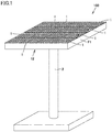
- Fig. 1 is a perspective view of a concentrator photovoltaic device using a case according to a first embodiment.
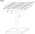
- Fig. 2 is a perspective view showing a configuration of a platform shown in Fig. 1 .
- a photovoltaic device 100 includes a plurality of photovoltaic modules 1 and a platform 2.
- Platform 2 includes a frame member F1, a solar azimuth indicator C1 not shown in the figures, and a driver M1 not shown in the figures.
- Solar azimuth indicator C1 includes a sensor for detecting a position of the sun.
- the plurality of photovoltaic modules 1 are fixedly arranged on frame member F1.
- Driver M1 recognizes the position of the sun based on a signal output from solar azimuth indicator C1, and changes an orientation of frame member F1 during a period of time from sunrise to sunset such that the respective light receiving surfaces of photovoltaic modules 1 face the sun, for example.
- each of accommodation portions E1 shown in Fig. 2 has a rectangular solid shape, but may have a cubic shape or the like.
- a panel case (entire frame) 12 having the plurality of accommodation portions E1 is in the form of a saucer partitioned into the plurality of sections (accommodation portions) by frame member F1. It should be noted that although each of the photovoltaic modules has a side wall composed of a resin as described below, even such a photovoltaic module exhibits sufficient mechanical strength when attached to panel case 12.
- Fig. 3 is a perspective view of the concentrator photovoltaic module using the case according to the first embodiment.
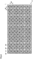
- Fig. 4 is a plan view of the concentrator photovoltaic module using the case according to the first embodiment.
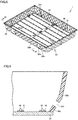
- Fig. 5 is a perspective view showing a detailed configuration of the case according to the first embodiment. It should be noted that since Fig. 5 illustrates an internal configuration of a case 21, no light collecting portion 22 is shown therein.
- photovoltaic module 1 includes case 21 having a rectangular solid shape or a cubic shape.
- Case 21 has a bottom portion 23, a side wall 24, and a light collecting portion 22.
- Side wall 24 corresponds to a side surface of case 21.
- Light collecting portion 22 is provided at the upper end of side wall 24, and bottom portion 23 is provided at the lower end of side wall 24. That is, light collecting portion 22 corresponds to the upper surface of case 21, and bottom portion 23 corresponds to the bottom surface of case 21.
- Bottom portion 23 is composed of aluminum, for example.
- Side wall 24 is composed of a resin. It should be noted that details of the configuration of side wall 24 will be described later.
- Light collecting portion 22 includes a plurality of Fresnel lenses 22f.
- Fresnel lenses 22f are disposed in the form of a tetragonal lattice, for example. Specifically, for example, Fresnel lenses 22f are disposed such that a distance between the respective centers of adjacent Fresnel lenses 22f is equally W1 among Fresnel lenses 22f.
- a plurality of power generation elements 30 and a plurality of FPCs (Flexible Printed Circuits) 31 are further included in case 21 of photovoltaic module 1.
- the plurality of FPCs 31 are disposed side by side in parallel or substantially in parallel with one another at bottom portion 23.
- a plurality of power generation elements 30 are mounted on each FPC 31.
- Each of power generation elements 30 is provided at a position corresponding to a Fresnel lens 22f, receives sunlight collected by the corresponding Fresnel lens 22f, and generates electric power depending on an amount of the received light.
- side wall 24 may be preferably inclined relative to the outer side of case 21, i.e., the outer surface side of the side wall.
- side wall 24 may be constituted of a main side plate 26a and a sub-side plate 26b.
- main side plate 26a may be formed to be inclined at a first angle relative to the outer surface side
- sub-side plate 26b may be formed to be inclined relative to the outer surface side at a second angle larger than the first angle.
- sub-side plate 26b may be formed at a part of a region on the outer surface of main side plate 26a.
- air holes 24h are formed in side wall 24.
- One air hole 24h is formed in each side wall 24 of case 21 as shown in Fig. 5 , for example. It should be noted that the number and size of air holes 24h are not limited as long as case 21 is configured such that flow of air is produced therein. For example, an air hole 24h may be formed in any one of side walls 24 of case 21.
- At least two air holes are preferably provided in the whole of case 21 because there are entrance and exit for air.
- the inside of case 21 can be avoided from being a sealed space, thereby maintaining a balance between pressure in the case and pressure of the external air.
- minimum air permeability can be secured by making a contrivance with regard to an opening area or shape of the air hole.
- Fig. 6 is a cross sectional view along a VI-VI cross section in Fig. 5 .
- Each of air holes 24h formed in side wall 24 is inclined from the inner surface side of side wall 24 to the outer surface side of side wall 24 downward, i.e., in a direction from the upper end of side wall 24 toward the lower end of side wall 24. It should be noted that the angle of inclination of air hole 24h is not particularly limited. Air hole 24h may be formed to extend straightly downward, for example.
- air hole 24h may be formed in sub-side plate 26b of side wall 24. Since sub-side plate 26b is inclined relative to the outer surface side at the angle larger than the angle of inclination of main side plate 26a, the inclination of air hole 24h can be increased more.
- Fig. 7 is a cross sectional view along a VII-VII cross section in Fig. 5 in order to illustrate a state in which the case of the photovoltaic module according to the first embodiment is attached to the frame member.
- case 21 may be fixed to frame member F1 in a different manner.
- photovoltaic module 1 includes power generation element 30 configured to generate power when receiving light; and closed case 21 in which power generation element 30 is accommodated.
- Case 21 includes: light collecting portion 22 provided with the lens (Fresnel lens 22f) for collecting sunlight; bottom portion 23 on which power generation element 30 is disposed; and side wall 24 defining the outer frame of bottom portion 23 and supporting light collecting portion 22.
- Side wall 24 includes air hole 24h inclined downward from the inner surface side of side wall 24 toward the outer surface side of side wall 24.
- a photovoltaic device may be used at a location with a large range of temperature variation.
- a change in temperature may cause expansion or contraction of the bottom portion, thereby changing a distance between the power generation element provided at the bottom portion and the Fresnel lens provided at the upper surface of the case.
- side wall 24 is composed of a resin. Therefore, even if the focal distance of the lens is changed in response to the change in temperature, the side wall is also expanded or contracted in response to the change in temperature, thereby changing the distance between the lens and the power generation element. As a result, even if the focal distance of the lens is changed, the amount of sunlight collected to the power generation element is prevented from being decreased significantly, whereby the power generation efficiency of the photovoltaic module can be suppressed from being decreased.
- the decrease in power generation efficiency of the photovoltaic module can be suppressed by the configuration in which air hole 24h is provided in side wall 24 of case 21 and side wall 24 is composed of a resin.
- a photovoltaic device is used outdoors, i.e., in an environment involving foreign matters such as rain water and dusts. Entrance of the foreign matters such as rain water and dusts into the case may cause decreased performance of the photovoltaic device or the like.
- air hole 24h is inclined downward from the inner surface side of side wall 24 toward the outer surface side of side wall 24, whereby the foreign matters such as rain water and dusts are unlikely to enter the inside of the case via air hole 24h.
- the rain water and dusts can be suppressed from entering the inside of the case, thereby suppressing decrease in performance of the photovoltaic module.
- a photovoltaic module 1 according to a second embodiment further includes partition plates 24g inside an air hole 24h provided in a side wall 24.
- partition plates 24g inside an air hole 24h provided in a side wall 24.
- Fig. 8 is a cross sectional view showing a configuration of a case according to the second embodiment.
- Fig. 9 is a cross sectional view showing a configuration of the partition plates shown in Fig. 8 more in detail.
- Fig. 10 is a cross sectional view showing a modification of the partition plates shown in Fig. 8 .
- Fig. 11 is a front view of the air hole and partition plates shown in Fig. 8 when viewed from outside.
- side wall 24 of photovoltaic module 1 according to the second embodiment includes partition plates 24g.
- side wall 24 further includes a projecting ring 24f and a filter 142.
- partition plates 24g are formed inside air hole 24h.
- partition plates 24g may be formed to cross the inner surface of side wall 24.
- partition plates 24g may be formed to divide air hole 24h into a plurality of sub-air holes 25.
- each of partition plates 24g at the inner surface side of side wall 24 may be formed to project relative to the inner surface of side wall 24.
- the end portion of partition plate 24g at the outer surface side of side wall 24 may be formed to be acute.
- partition plate 24g in this way, even if water flows on partition plate 24g, the water is facilitated to fall downward, whereby the water can be further suppressed from entering the inside of the case.
- partition plate 24g may be formed to extend in a direction from the upper end of side wall 24 toward the lower end of side wall 24.
- the direction in which partition plate 24g is formed coincides with a direction in which natural convection is produced, thereby causing a straightening action with which air can efficiently flow upward and downward within the case. Accordingly, excessive temperature increase in the case can be suppressed further.
- partition plates 24g are formed such that the whole of air hole 24h is covered with partition plates 24g when case 21 is viewed in a side view. According to such a configuration of partition plates 24g, water can be further suppressed from entering the inside of the case even when slanting rain is falling, for example.
- projecting ring 24f is formed to surround the outer circumference of air hole 24h at the inner surface side of side wall 24. According to the configuration of such a projecting ring 24f, air passing through air hole 24h can be guided, thereby further suppressing excessive temperature increase in the case.
- filter 142 is provided on the end portion of each of projecting ring 24f and partition plate 24g at the inner surface side of side wall 24 to cover air hole 24h.
- Filter 142 is preferably a mesh-like member molded using tetrafluoroethylene resin (PTFE).
- Filter 142 is melted to be joined to the end portion of each of projecting ring 24f and partition plate 24g at the inner surface side of side wall 24. According to the configuration in which filter 142 is provided, foreign matters, such as rain water, water droplets, or insects, can be further suppressed from entering.
- side wall 24 may have a black color by mixing a black pigment, such as carbon black, with the resin for forming side wall 24.
- Filter 142 is a white mesh-like member molded using tetrafluoroethylene resin (PTFE) or the like.
- PTFE tetrafluoroethylene resin
- partition plates 24g are formed inside air hole 24h in photovoltaic module 1 according to the second embodiment, the width of the opening of air hole 24h is substantially narrower than that in the case where such partition plates 24g are not provided. Hence, foreign matters, such as rain water and dusts, are unlikely to enter the inside of the case via air hole 24h, thereby further suppressing the performance of the photovoltaic module from being decreased due to entrance of rain water or dusts into the inside of the case.
- 1 photovoltaic module
- 2 platform; 12: panel case; 21: case; 22: light collecting portion; 22f: Fresnel lens (lens); 23: bottom portion; 24: side wall; 24f: projecting ring; 24g: partition plate; 24h: air hole; 25: sub-air hole; 26a: main side plate; 26b: sub-side plate; 28: attaching hole; 29: bolt; 30: power generation element; 31: FPC; 100: photovoltaic device; 142: filter; C1: solar azimuth indicator; E1: accommodation portion; F1: frame member; M1: driver.
Landscapes
- Physics & Mathematics (AREA)
- General Physics & Mathematics (AREA)
- Optics & Photonics (AREA)
- Life Sciences & Earth Sciences (AREA)
- Sustainable Development (AREA)
- Health & Medical Sciences (AREA)
- Toxicology (AREA)
- Photovoltaic Devices (AREA)
Abstract
Description
- The present invention relates to an enclosure for a photovoltaic device, particularly, a photovoltaic module in which a power generation element provided in the enclosure receives sunlight and generates electric power depending on an amount of the received light.
- The present application claims a priority based on Japanese Patent Application No.
2015-197903 filed on October 5, 2015 - Conventionally, a photovoltaic module for collecting sunlight and converting it into electric power has been developed. For example, the following art is disclosed in Patent Document 1 (
WO 2013/150031 ). That is, a concentrator photovoltaic device described inPatent Document 1 includes a lens and a power generation element in its case, wherein a distance between the lens and the power generation element is adjusted by introducing gas into the case. - Moreover, for example, the following art is disclosed in Patent Document 2 (
US Patent No. 8,592,738 ). - That is, a device for checking the optical axis of incoming light is attached to a concentrator photovoltaic device described in
Patent Document 2. - Next, for example, the following art is disclosed in Patent Document 3 (Japanese Patent Laying-Open No.
2008-84955 - Moreover, for example, the following art is disclosed in Patent Document 4 (Japanese Patent Laying-Open No.
2008-4661 -
- PTD 1:
WO 2013/150031 - PTD 2:
US Patent No. 8,592,738 - PTD 3: Japanese Patent Laying-Open No.
2008-84955 - PTD 4: Japanese Patent Laying-Open No.
2008-4661 - PTD 5: Japanese Patent Laying-Open No.
7-274742 - An enclosure for a concentrator photovoltaic device according to one embodiment of the present invention includes a side wall having an upper end, a lower end, an inner surface, and an outer surface, the side wall being composed of a resin, the side wall being provided with an air hole extending through the inner and outer surfaces of the side wall, the air hole being inclined from the inner surface of the side wall to the outer surface of the side wall in a direction from the upper end of the side wall toward the lower end of the side wall.
-
-
Fig. 1 is a perspective view of a concentrator photovoltaic device using a case according to a first embodiment. -
Fig. 2 is a perspective view showing a configuration of a platform shown inFig. 1 . -
Fig. 3 is a perspective view of a concentrator photovoltaic module using the case according to the first embodiment. -
Fig. 4 is a plan view of the concentrator photovoltaic module using the case according to the first embodiment. -
Fig. 5 is a perspective view showing a detailed configuration of the case according to the first embodiment. -
Fig. 6 is a cross sectional view along a VI-VI cross section inFig. 5 . -
Fig. 7 is a cross sectional view along a VII-VII cross section inFig. 5 . -
Fig. 8 is a cross sectional view showing a configuration of a case according to a second embodiment. -
Fig. 9 is a cross sectional view showing a configuration of partition plates shown inFig. 8 more in detail. -
Fig. 10 is a cross sectional view showing a modification of the partition plates shown inFig. 8 . -
Fig. 11 is a front view of an air hole and the partition plates shown inFig. 8 when viewed from outside. - A common and ultimate challenge among the above-described conventional arts is to exhibit power generation efficiency and other performance under a severe outdoor environment; however, sufficient performance cannot be always achieved under such a severe environment.
- More specifically, there are the following problems. Since the case is composed of a metal in each of the above-described conventional arts, the bottom portion of the case is expanded or contracted in response to a change in temperature, thereby changing a distance between the power generation element provided at the bottom portion and the Fresnel lens provided at the upper surface of the case. Accordingly, the amount of sunlight collected to the power generation element is decreased significantly to decrease the power generation efficiency of the photovoltaic module, with the result that sufficient power generation efficiency is not obtained.
- Meanwhile, for example, the concentrator photovoltaic unit described in Patent Document 3 is provided with an air hole cover for covering the air hole provided in the end portion of the elongated frame in order to prevent foreign matters, such as rain water or dusts, from entering the inside of the elongated frame via the air hole. However, even with such a configuration, the entrance of foreign matters may be unable to be prevented sufficiently, with the result that the performance or the like of the concentrator photovoltaic unit may be decreased due to the entrance of foreign matters.
- In view of such problems, the present disclosure provides a configuration capable of further increasing power generation efficiency of a photovoltaic module and suppressing performance thereof from being decreased due to entrance of undesired matters into a case, such as dusts, water droplets, and foreign matters.
- According to the present disclosure, there can be provided a configuration capable of further increasing power generation efficiency of a concentrator photovoltaic module and suppressing entrance of undesired matters into the case, such as dusts, water droplets, and foreign matters.
- First, embodiments of the present invention are listed and described.
- (1) An enclosure for a concentrator photovoltaic device according to one embodiment of the present invention includes a side wall having an upper end, a lower end, an inner surface, and an outer surface, the side wall being composed of a resin, the side wall being provided with an air hole extending through the inner and outer surfaces of the side wall, the air hole being inclined from the inner surface of the side wall to the outer surface of the side wall in a direction from the upper end of the side wall toward the lower end of the side wall. It should be noted that the case where the air hole is inclined from the inner surface of the side wall to the outer surface of the side wall in the direction from the upper end of the side wall toward the lower end of the side wall encompasses a case where the air hole is formed to extend straightly downward from the inner surface of the side wall to the outer surface of the side wall.
According to such a configuration in which the inclined air hole is provided in the side wall of the enclosure, a temperature in the case becomes close to a temperature outside the case, thereby suppressing excessive temperature increase. Moreover, undesired matters such as dusts, water droplets, and foreign matters can be suppressed from entering the inside of the case. Moreover, the side wall is composed of a resin. Therefore, even if the focal distance of a lens is changed in response to a change in temperature, the side wall is also expanded or contracted in response to the change in temperature, thereby changing the distance between the lens and a power generation element. Hence, even if the focal distance of the lens is changed, the amount of sunlight collected to the power generation element is prevented from being decreased significantly, whereby the power generation efficiency of the photovoltaic module can be suppressed from being decreased. - (2) In the enclosure for the concentrator photovoltaic device according to (1), the side wall may be inclined relative to the outer surface side.
According to such a configuration of the side wall, the inclination of the air hole can be large, whereby undesired matters such as dusts, water droplets, and foreign matters can be further suppressed from entering the inside of the case. - (3) In the enclosure for the concentrator photovoltaic device according to (1), the side wall may have a partition plate inside the air hole, the partition plate being formed to cross the inner surface of the side wall.
According to such a configuration in which the partition plate is provided inside the air hole, undesired matters such as dusts, water droplets, and foreign matters can be further suppressed from entering the inside of the case. - (4) In the enclosure for the concentrator photovoltaic device according to (3), the partition plate may project relative to the inner surface of the side wall.
According to such a configuration in which the partition plate projects relative to the inner surface of the side wall, the width of the side wall can be longer than the length of the air hole, thereby increasing the strength of the side wall. - (5) The enclosure for the concentrator photovoltaic device according to (3) may include a projecting ring formed to surround an outer circumference of the air hole at the inner surface of the side wall.
According to such a configuration in which the projecting ring is provided at the inner surface of the side wall, air passing through the air hole can be guided, thereby further suppressing excessive temperature increase in the case. - (6) In the enclosure for the concentrator photovoltaic device according to (3), the partition plate may be formed to extend in the direction from the upper end of the side wall toward the lower end of the side wall.
According to such a configuration of the partition plate, a straightening action is produced to permit air to efficiently flow upward and downward within the case, thereby further suppressing excessive temperature increase in the case. - (7) In the enclosure for the concentrator photovoltaic device according to (1), the side wall may have a main side plate and a sub-side plate, the main side plate may be formed to be inclined at a first angle relative to the outer surface side of the side wall, and the sub-side plate may be formed to be inclined relative to the outer surface side of the side wall at a second angle larger than the first angle.
According to such a configuration in which the side wall has the main side plate and the sub-side plate, strength and rigidity of the case can be improved. - (8) In the enclosure for the concentrator photovoltaic device according to (7), the air hole may be formed in the sub-side plate.
According to such a configuration in which the air hole is formed in the sub-side plate, the inclination of the air hole can be large, whereby undesired matters such as dusts, water droplets, and foreign matters can be further suppressed from entering the inside of the case. - (9) In the enclosure for the concentrator photovoltaic device according to (7), the sub-side plate may be formed at the outer surface side of the side wall.
According to such a configuration in which the sub-side plate is formed at the outer surface side of the side wall, strength and rigidity of the case can be improved. - (10) In the enclosure for the concentrator photovoltaic device according to (3), the partition plate may be formed to divide the air hole into at least two sub-air holes.
According to such a configuration in which the partition plate is formed to divide the air hole into the plurality of sub-air holes, durability of the air hole can be improved. - (11) In the enclosure for the concentrator photovoltaic device according to (3), the partition plate may be formed such that a whole of the air hole is covered with the partition plate when the enclosure for the concentrator photovoltaic device is viewed in a side view.
According to such a configuration in which the partition plate is formed such that the whole of the air hole is covered with the partition plate when the enclosure for the concentrator photovoltaic device is viewed in a side view, water can be further suppressed from entering the inside of the case even when slanting rain is falling, for example. - (12) In the enclosure for the concentrator photovoltaic device according to (3), the partition plate may include an end portion at the outer surface side of the side wall and an end portion at the inner surface side of the side wall, and the end portion at the outer surface side of the side wall may be formed to be acute.
According to such a configuration in which the end portion of the partition plate at the outer surface side of the side wall is acute, even if water flows on the partition plate, the water is facilitated to fall downward, whereby the water can be further suppressed from entering the inside of the case. - (13) A concentrator photovoltaic device according to one embodiment of the present invention includes the enclosure for the concentrator photovoltaic device as recited in any one of (1) to (12).
- According to such a configuration having the enclosure for the concentrator photovoltaic device, a temperature in the case becomes close to a temperature outside the case, thereby suppressing excessive temperature increase. Further, if the focal distance of the lens is changed in response to the change in temperature, the side wall composed of a resin is also expanded or contracted in response to the change in temperature, thereby changing the distance between the lens and the power generation element. Hence, even if the focal distance of the lens is changed, the amount of sunlight collected to the power generation element is prevented from being decreased significantly, whereby the power generation efficiency of the photovoltaic module can be suppressed from being decreased.
- The following describes embodiments of the present invention with reference to figures. It should be noted that the same or corresponding portions in the figures are given the same reference characters. Moreover, at least a part of the embodiments described below may be appropriately combined.
-
Fig. 1 is a perspective view of a concentrator photovoltaic device using a case according to a first embodiment.Fig. 2 is a perspective view showing a configuration of a platform shown inFig. 1 . - As shown in
Fig. 1 , aphotovoltaic device 100 includes a plurality ofphotovoltaic modules 1 and aplatform 2.Platform 2 includes a frame member F1, a solar azimuth indicator C1 not shown in the figures, and a driver M1 not shown in the figures. Solar azimuth indicator C1 includes a sensor for detecting a position of the sun. The plurality ofphotovoltaic modules 1 are fixedly arranged on frame member F1. - Driver M1 recognizes the position of the sun based on a signal output from solar azimuth indicator C1, and changes an orientation of frame member F1 during a period of time from sunrise to sunset such that the respective light receiving surfaces of
photovoltaic modules 1 face the sun, for example. - As shown in
Fig. 2 , in frame member F1 ofplatform 2, a plurality of columns are provided to cross one another longitudinally and laterally. Into each of rectangular-solid-shaped accommodation portions E1 (each having no upper surface and having a bottom surface) formed by this frame member F1, onephotovoltaic module 1 is inserted. It should be noted that each of accommodation portions E1 shown inFig. 2 has a rectangular solid shape, but may have a cubic shape or the like. - A panel case (entire frame) 12 having the plurality of accommodation portions E1 is in the form of a saucer partitioned into the plurality of sections (accommodation portions) by frame member F1. It should be noted that although each of the photovoltaic modules has a side wall composed of a resin as described below, even such a photovoltaic module exhibits sufficient mechanical strength when attached to
panel case 12. -
Fig. 3 is a perspective view of the concentrator photovoltaic module using the case according to the first embodiment.Fig. 4 is a plan view of the concentrator photovoltaic module using the case according to the first embodiment.Fig. 5 is a perspective view showing a detailed configuration of the case according to the first embodiment. It should be noted that sinceFig. 5 illustrates an internal configuration of acase 21, nolight collecting portion 22 is shown therein. - As shown in
Fig. 3 andFig. 4 ,photovoltaic module 1 includescase 21 having a rectangular solid shape or a cubic shape.Case 21 has abottom portion 23, aside wall 24, and alight collecting portion 22.Side wall 24 corresponds to a side surface ofcase 21.Light collecting portion 22 is provided at the upper end ofside wall 24, andbottom portion 23 is provided at the lower end ofside wall 24. That is, light collectingportion 22 corresponds to the upper surface ofcase 21, andbottom portion 23 corresponds to the bottom surface ofcase 21. -
Bottom portion 23 is composed of aluminum, for example.Side wall 24 is composed of a resin. It should be noted that details of the configuration ofside wall 24 will be described later. -
Light collecting portion 22 includes a plurality ofFresnel lenses 22f. Inlight collecting portion 22,Fresnel lenses 22f are disposed in the form of a tetragonal lattice, for example. Specifically, for example,Fresnel lenses 22f are disposed such that a distance between the respective centers ofadjacent Fresnel lenses 22f is equally W1 amongFresnel lenses 22f. - As shown in
Fig. 5 , a plurality ofpower generation elements 30 and a plurality of FPCs (Flexible Printed Circuits) 31 are further included incase 21 ofphotovoltaic module 1. - As shown in
Fig. 5 , the plurality ofFPCs 31 are disposed side by side in parallel or substantially in parallel with one another atbottom portion 23. A plurality ofpower generation elements 30 are mounted on eachFPC 31. - Each of
power generation elements 30 is provided at a position corresponding to aFresnel lens 22f, receives sunlight collected by the correspondingFresnel lens 22f, and generates electric power depending on an amount of the received light. - As shown in
Fig. 5 ,side wall 24 may be preferably inclined relative to the outer side ofcase 21, i.e., the outer surface side of the side wall. - Preferably, as shown in
Fig. 5 ,side wall 24 may be constituted of amain side plate 26a and asub-side plate 26b. Moreover, preferably, as shown inFig. 5 ,main side plate 26a may be formed to be inclined at a first angle relative to the outer surface side, andsub-side plate 26b may be formed to be inclined relative to the outer surface side at a second angle larger than the first angle. Further, preferably, as shown inFig. 5 ,sub-side plate 26b may be formed at a part of a region on the outer surface ofmain side plate 26a. - As shown in
Fig. 5 ,air holes 24h are formed inside wall 24. - One
air hole 24h is formed in eachside wall 24 ofcase 21 as shown inFig. 5 , for example. It should be noted that the number and size ofair holes 24h are not limited as long ascase 21 is configured such that flow of air is produced therein. For example, anair hole 24h may be formed in any one ofside walls 24 ofcase 21. - It should be noted that at least two air holes are preferably provided in the whole of
case 21 because there are entrance and exit for air. However, even when one air hole is provided in the whole ofcase 21, the inside ofcase 21 can be avoided from being a sealed space, thereby maintaining a balance between pressure in the case and pressure of the external air. Moreover, minimum air permeability can be secured by making a contrivance with regard to an opening area or shape of the air hole. -
Fig. 6 is a cross sectional view along a VI-VI cross section inFig. 5 . - Each of
air holes 24h formed inside wall 24 is inclined from the inner surface side ofside wall 24 to the outer surface side ofside wall 24 downward, i.e., in a direction from the upper end ofside wall 24 toward the lower end ofside wall 24. It should be noted that the angle of inclination ofair hole 24h is not particularly limited.Air hole 24h may be formed to extend straightly downward, for example. - Preferably, as shown in
Fig. 6 ,air hole 24h may be formed insub-side plate 26b ofside wall 24. Sincesub-side plate 26b is inclined relative to the outer surface side at the angle larger than the angle of inclination ofmain side plate 26a, the inclination ofair hole 24h can be increased more. -
Fig. 7 is a cross sectional view along a VII-VII cross section inFig. 5 in order to illustrate a state in which the case of the photovoltaic module according to the first embodiment is attached to the frame member. - As shown in
Fig. 7 , whencase 21 ofphotovoltaic module 1 is inserted in accommodation portion E1 formed by frame member F1,bottom portion 23 ofcase 21 is brought into contact with the upper surface of frame member F1. In such a state, for example, abolt 29 is inserted into an attachinghole 28 formed inbottom portion 23 andside wall 24, thereby fixingcase 21 to frame member F1. - It should be noted that instead of the configuration in which
case 21 is fixed to frame member F1 by insertingbolt 29 into attachinghole 28,case 21 may be fixed to frame member F1 in a different manner. - As described above,
photovoltaic module 1 includespower generation element 30 configured to generate power when receiving light; andclosed case 21 in whichpower generation element 30 is accommodated.Case 21 includes:light collecting portion 22 provided with the lens (Fresnel lens 22f) for collecting sunlight;bottom portion 23 on whichpower generation element 30 is disposed; andside wall 24 defining the outer frame ofbottom portion 23 and supportinglight collecting portion 22.Side wall 24 includesair hole 24h inclined downward from the inner surface side ofside wall 24 toward the outer surface side ofside wall 24. - Here, a photovoltaic device may be used at a location with a large range of temperature variation. A change in temperature may cause expansion or contraction of the bottom portion, thereby changing a distance between the power generation element provided at the bottom portion and the Fresnel lens provided at the upper surface of the case.
- When the distance between the power generation element and the Fresnel lens is changed in this way, the distance does not coincide with a focal distance of the Fresnel lens, with the result that sunlight may be unable to be collected efficiently.
- On the other hand, in
photovoltaic module 1 according to the first embodiment,air hole 24h is formed inside wall 24. Hence, flow of air is produced incase 21, thereby suppressing a significant change in temperature incase 21. Accordingly,bottom portion 23 can be suppressed from being expanded and contracted. - Moreover, in the photovoltaic module according to the first embodiment,
side wall 24 is composed of a resin. Therefore, even if the focal distance of the lens is changed in response to the change in temperature, the side wall is also expanded or contracted in response to the change in temperature, thereby changing the distance between the lens and the power generation element. As a result, even if the focal distance of the lens is changed, the amount of sunlight collected to the power generation element is prevented from being decreased significantly, whereby the power generation efficiency of the photovoltaic module can be suppressed from being decreased. - Thus, the decrease in power generation efficiency of the photovoltaic module can be suppressed by the configuration in which
air hole 24h is provided inside wall 24 ofcase 21 andside wall 24 is composed of a resin. - Meanwhile, a photovoltaic device is used outdoors, i.e., in an environment involving foreign matters such as rain water and dusts. Entrance of the foreign matters such as rain water and dusts into the case may cause decreased performance of the photovoltaic device or the like.
- To address this, in
photovoltaic module 1 according to the first embodiment,air hole 24h is inclined downward from the inner surface side ofside wall 24 toward the outer surface side ofside wall 24, whereby the foreign matters such as rain water and dusts are unlikely to enter the inside of the case viaair hole 24h. - Thus, according to the configuration in which
air hole 24h is inclined downward from the inner surface side ofside wall 24 toward the outer surface side ofside wall 24, the rain water and dusts can be suppressed from entering the inside of the case, thereby suppressing decrease in performance of the photovoltaic module. - A
photovoltaic module 1 according to a second embodiment further includespartition plates 24g inside anair hole 24h provided in aside wall 24. Here, the following mainly describes a difference from the above-describedphotovoltaic module 1 according to the first embodiment. -
Fig. 8 is a cross sectional view showing a configuration of a case according to the second embodiment.Fig. 9 is a cross sectional view showing a configuration of the partition plates shown inFig. 8 more in detail.Fig. 10 is a cross sectional view showing a modification of the partition plates shown inFig. 8 .Fig. 11 is a front view of the air hole and partition plates shown inFig. 8 when viewed from outside. - As shown in
Fig. 8 , in comparison withcase 21 according to the first embodiment,side wall 24 ofphotovoltaic module 1 according to the second embodiment includespartition plates 24g. Preferably,side wall 24 further includes a projectingring 24f and afilter 142. - As shown in
Fig. 9 ,partition plates 24g are formed insideair hole 24h. - Preferably, as shown in
Fig. 11 ,partition plates 24g may be formed to cross the inner surface ofside wall 24. In other words,partition plates 24g may be formed to divideair hole 24h into a plurality ofsub-air holes 25. By formingpartition plates 24g in this way,side wall 24 can be reinforced. - Preferably, as shown in
Fig. 9 , the end portion of each ofpartition plates 24g at the inner surface side ofside wall 24 may be formed to project relative to the inner surface ofside wall 24. - Preferably, as shown in
Fig. 9 , the end portion ofpartition plate 24g at the outer surface side ofside wall 24 may be formed to be acute. By formingpartition plate 24g in this way, even if water flows onpartition plate 24g, the water is facilitated to fall downward, whereby the water can be further suppressed from entering the inside of the case. - Preferably, as shown in
Fig. 10 ,partition plate 24g may be formed to extend in a direction from the upper end ofside wall 24 toward the lower end ofside wall 24. By formingpartition plate 24g in this way, the direction in whichpartition plate 24g is formed coincides with a direction in which natural convection is produced, thereby causing a straightening action with which air can efficiently flow upward and downward within the case. Accordingly, excessive temperature increase in the case can be suppressed further. - Preferably, as shown in
Fig. 11 ,partition plates 24g are formed such that the whole ofair hole 24h is covered withpartition plates 24g whencase 21 is viewed in a side view. According to such a configuration ofpartition plates 24g, water can be further suppressed from entering the inside of the case even when slanting rain is falling, for example. - As shown in
Fig. 9 , projectingring 24f is formed to surround the outer circumference ofair hole 24h at the inner surface side ofside wall 24. According to the configuration of such a projectingring 24f, air passing throughair hole 24h can be guided, thereby further suppressing excessive temperature increase in the case. - As shown in
Fig. 9 ,filter 142 is provided on the end portion of each of projectingring 24f andpartition plate 24g at the inner surface side ofside wall 24 to coverair hole 24h. -
Filter 142 is preferably a mesh-like member molded using tetrafluoroethylene resin (PTFE). -
Filter 142 is melted to be joined to the end portion of each of projectingring 24f andpartition plate 24g at the inner surface side ofside wall 24. According to the configuration in which filter 142 is provided, foreign matters, such as rain water, water droplets, or insects, can be further suppressed from entering. - Moreover, preferably, in the configuration shown in
Fig. 9 ,side wall 24 may have a black color by mixing a black pigment, such as carbon black, with the resin for formingside wall 24.Filter 142 is a white mesh-like member molded using tetrafluoroethylene resin (PTFE) or the like. Hence, whenfilter 142 is melted to be joined to projectingring 24f andpartition plates 24g, the melted black resin of projectingring 24f andpartition plate 24g enters a space infilter 142, thereby forming a black-and-white stripe pattern onfilter 142. Such a black-and-white stripe pattern has an insect repellent effect. Hence, according to such a configuration offilter 142,side wall 24, projectingring 24f, andpartition plate 24g, insects can be further suppressed from entering the inside of the case. - Since
partition plates 24g are formed insideair hole 24h inphotovoltaic module 1 according to the second embodiment, the width of the opening ofair hole 24h is substantially narrower than that in the case wheresuch partition plates 24g are not provided. Hence, foreign matters, such as rain water and dusts, are unlikely to enter the inside of the case viaair hole 24h, thereby further suppressing the performance of the photovoltaic module from being decreased due to entrance of rain water or dusts into the inside of the case. - The embodiments disclosed herein are illustrative and non-restrictive in any respect. The scope of the present invention is defined by the terms of the claims, rather than the embodiments described above, and is intended to include any modifications within the scope and meaning equivalent to the terms of the claims.
- 1: photovoltaic module; 2: platform; 12: panel case; 21: case; 22: light collecting portion; 22f: Fresnel lens (lens); 23: bottom portion; 24: side wall; 24f: projecting ring; 24g: partition plate; 24h: air hole; 25: sub-air hole; 26a: main side plate; 26b: sub-side plate; 28: attaching hole; 29: bolt; 30: power generation element; 31: FPC; 100: photovoltaic device; 142: filter; C1: solar azimuth indicator; E1: accommodation portion; F1: frame member; M1: driver.
Claims (13)
- An enclosure for a concentrator photovoltaic device, the enclosure comprising a side wall having an upper end, a lower end, an inner surface, and an outer surface, the side wall being composed of a resin,
the side wall being provided with an air hole extending through the inner and outer surfaces of the side wall,
the air hole being inclined from the inner surface of the side wall to the outer surface of the side wall in a direction from the upper end of the side wall toward the lower end of the side wall. - The enclosure for the concentrator photovoltaic device according to claim 1, wherein the side wall is inclined relative to the outer surface side.
- The enclosure for the concentrator photovoltaic device according to claim 1, wherein the side wall has a partition plate inside the air hole.
- The enclosure for the concentrator photovoltaic device according to claim 3, wherein the partition plate projects relative to the inner surface of the side wall.
- The enclosure for the concentrator photovoltaic device according to claim 3, the enclosure comprising a projecting ring formed to surround an outer circumference of the air hole at the inner surface of the side wall.
- The enclosure for the concentrator photovoltaic device according to claim 3, wherein the partition plate is formed to extend in the direction from the upper end of the side wall toward the lower end of the side wall.
- The enclosure for the concentrator photovoltaic device according to claim 1, wherein the side wall has a main side plate and a sub-side plate, the main side plate is formed to be inclined at a first angle relative to the outer surface side of the side wall, and the sub-side plate is formed to be inclined relative to the outer surface side of the side wall at a second angle larger than the first angle.
- The enclosure for the concentrator photovoltaic device according to claim 7, wherein the air hole is formed in the sub-side plate.
- The enclosure for the concentrator photovoltaic device according to claim 7, wherein the sub-side plate is formed at the outer surface side of the side wall.
- The enclosure for the concentrator photovoltaic device according to claim 3, wherein the partition plate is formed to divide the air hole into at least two sub-air holes.
- The enclosure for the concentrator photovoltaic device according to claim 3, wherein the partition plate is formed such that a whole of the air hole is covered with the partition plate when the enclosure for the concentrator photovoltaic device is viewed in a side view.
- The enclosure for the concentrator photovoltaic device according to claim 3, wherein the partition plate includes an end portion at the outer surface side of the side wall and an end portion at the inner surface side of the side wall, and the end portion at the outer surface side of the side wall is formed to be acute.
- A concentrator photovoltaic device comprising the enclosure for the concentrator photovoltaic device as recited in any one of claims 1 to 12.
Applications Claiming Priority (2)
| Application Number | Priority Date | Filing Date | Title |
|---|---|---|---|
| JP2015197903A JP6512057B2 (en) | 2015-10-05 | 2015-10-05 | Box for concentrating solar power generation apparatus and concentrating solar power generation apparatus using the same |
| PCT/JP2016/079086 WO2017061335A1 (en) | 2015-10-05 | 2016-09-30 | Enclosure for concentrated solar power generation device and concentrated solar power generation device using same |
Publications (3)
| Publication Number | Publication Date |
|---|---|
| EP3361629A1 true EP3361629A1 (en) | 2018-08-15 |
| EP3361629A4 EP3361629A4 (en) | 2019-05-01 |
| EP3361629B1 EP3361629B1 (en) | 2021-03-31 |
Family
ID=58487592
Family Applications (1)
| Application Number | Title | Priority Date | Filing Date |
|---|---|---|---|
| EP16853489.9A Active EP3361629B1 (en) | 2015-10-05 | 2016-09-30 | Enclosure for concentrated solar power generation device and concentrated solar power generation device using same |
Country Status (9)
| Country | Link |
|---|---|
| US (1) | US10389295B2 (en) |
| EP (1) | EP3361629B1 (en) |
| JP (1) | JP6512057B2 (en) |
| CN (1) | CN107925381B (en) |
| AU (1) | AU2016335640B2 (en) |
| ES (1) | ES2863298T3 (en) |
| MA (1) | MA45302B1 (en) |
| TW (1) | TW201720051A (en) |
| WO (1) | WO2017061335A1 (en) |
Cited By (2)
| Publication number | Priority date | Publication date | Assignee | Title |
|---|---|---|---|---|
| EP3667740A4 (en) * | 2017-08-07 | 2021-05-05 | Sumitomo Electric Industries, Ltd. | CONCENTRATOR PHOTOVOLTAIC MODULE, CONCENTRATOR PHOTOVOLTAIC PANEL, CONCENTRATOR PHOTOVOLTAIC DEVICE, AND METHOD FOR MANUFACTURING A CONCENTRATOR PHOTOVOLTAIC MODULE |
| EP3667741A4 (en) * | 2017-08-07 | 2021-05-05 | Sumitomo Electric Industries, Ltd. | CONCENTRATOR PHOTOVOLTAIC MODULE, CONCENTRATOR PHOTOVOLTAIC PANEL AND CONCENTRATOR PHOTOVOLTAIC DEVICE |
Families Citing this family (3)
| Publication number | Priority date | Publication date | Assignee | Title |
|---|---|---|---|---|
| TWI625041B (en) * | 2017-06-14 | 2018-05-21 | 太陽光電能源科技股份有限公司 | Suspended solar generator apparatus with sun tracking function |
| JP7331841B2 (en) | 2018-04-18 | 2023-08-23 | 住友電気工業株式会社 | Pressure inspection method for housing unit for photovoltaic power generation device |
| CN111609370A (en) * | 2020-05-19 | 2020-09-01 | 田聪 | Device capable of ensuring brightness of solar street lamp in rainy days based on capacitance sensing |
Family Cites Families (20)
| Publication number | Priority date | Publication date | Assignee | Title |
|---|---|---|---|---|
| JPH07274742A (en) | 1994-04-13 | 1995-10-24 | Toshio Yamamura | Agricultural covering material having insect-repelling properties and its production |
| JP2000156518A (en) * | 1998-09-17 | 2000-06-06 | Nippon Telegr & Teleph Corp <Ntt> | Solar power system |
| JP4061349B2 (en) * | 1999-02-03 | 2008-03-19 | フクビ化学工業株式会社 | Aeration drainer and aeration drainage structure |
| JP2002289897A (en) * | 2001-03-23 | 2002-10-04 | Canon Inc | Concentrating solar cell module and concentrating solar power generation system |
| US8957301B2 (en) * | 2011-02-14 | 2015-02-17 | Robert Lyden | Solar cell, module, array, network, and power grid |
| JP4525103B2 (en) * | 2004-02-19 | 2010-08-18 | パナソニック電工株式会社 | Piping cover |
| JP5013684B2 (en) * | 2005-06-07 | 2012-08-29 | シャープ株式会社 | Condensing lens, condensing lens structure, concentrating solar power generation device, and manufacturing method of condensing lens structure |
| JP2008004661A (en) | 2006-06-21 | 2008-01-10 | Daido Steel Co Ltd | Concentrating solar power generator |
| JP4953745B2 (en) | 2006-09-26 | 2012-06-13 | シャープ株式会社 | Concentrating solar power generation unit and concentrating solar power generation device |
| US7855336B2 (en) | 2007-10-30 | 2010-12-21 | Opel, Inc. | Concentrated solar photovoltaic module with protective light shielding |
| US20090188560A1 (en) | 2008-01-29 | 2009-07-30 | Sen-Tien Lee | Concentrating photovoltaic apparatus |
| US20110263067A1 (en) * | 2008-02-11 | 2011-10-27 | Emcore Solar Power, Inc. | Methods of Forming a Concentrating Photovoltaic Module |
| US9331228B2 (en) * | 2008-02-11 | 2016-05-03 | Suncore Photovoltaics, Inc. | Concentrated photovoltaic system modules using III-V semiconductor solar cells |
| TWM378483U (en) * | 2009-09-23 | 2010-04-11 | Everphoton Energy Corp | Solar power module |
| CN201726343U (en) * | 2010-06-19 | 2011-01-26 | 天津蓝天太阳科技有限公司 | Frame type concentrating photovoltaic component |
| US8592738B1 (en) | 2010-07-01 | 2013-11-26 | Suncore Photovoltaics, Inc. | Alignment device for use with a solar tracking photovoltaic array |
| KR100997547B1 (en) * | 2010-07-19 | 2010-11-30 | 홍철규 | Concentrative photovoltaic generating apparatus |
| US20120325289A1 (en) * | 2011-06-24 | 2012-12-27 | Deck Christopher J | High concentrator photovoltaic solar module |
| FR2988909B1 (en) | 2012-04-03 | 2014-12-12 | Soitec Solar Gmbh | PHOTOVOLTAIC MODULE WITH ADJUSTABLE HEIGHT CONCENTRATION |
| KR20130133573A (en) * | 2012-05-29 | 2013-12-09 | 서울반도체 주식회사 | Led back light unit and led television comprising the same |
-
2015
- 2015-10-05 JP JP2015197903A patent/JP6512057B2/en not_active Expired - Fee Related
-
2016
- 2016-09-30 AU AU2016335640A patent/AU2016335640B2/en not_active Ceased
- 2016-09-30 CN CN201680045951.8A patent/CN107925381B/en not_active Expired - Fee Related
- 2016-09-30 WO PCT/JP2016/079086 patent/WO2017061335A1/en not_active Ceased
- 2016-09-30 ES ES16853489T patent/ES2863298T3/en active Active
- 2016-09-30 MA MA45302A patent/MA45302B1/en unknown
- 2016-09-30 US US15/743,962 patent/US10389295B2/en active Active
- 2016-09-30 EP EP16853489.9A patent/EP3361629B1/en active Active
- 2016-10-04 TW TW105132074A patent/TW201720051A/en unknown
Cited By (2)
| Publication number | Priority date | Publication date | Assignee | Title |
|---|---|---|---|---|
| EP3667740A4 (en) * | 2017-08-07 | 2021-05-05 | Sumitomo Electric Industries, Ltd. | CONCENTRATOR PHOTOVOLTAIC MODULE, CONCENTRATOR PHOTOVOLTAIC PANEL, CONCENTRATOR PHOTOVOLTAIC DEVICE, AND METHOD FOR MANUFACTURING A CONCENTRATOR PHOTOVOLTAIC MODULE |
| EP3667741A4 (en) * | 2017-08-07 | 2021-05-05 | Sumitomo Electric Industries, Ltd. | CONCENTRATOR PHOTOVOLTAIC MODULE, CONCENTRATOR PHOTOVOLTAIC PANEL AND CONCENTRATOR PHOTOVOLTAIC DEVICE |
Also Published As
| Publication number | Publication date |
|---|---|
| MA45302A (en) | 2018-08-15 |
| JP6512057B2 (en) | 2019-05-15 |
| MA45302B1 (en) | 2021-06-30 |
| JP2017073853A (en) | 2017-04-13 |
| US10389295B2 (en) | 2019-08-20 |
| AU2016335640A1 (en) | 2018-02-01 |
| EP3361629A4 (en) | 2019-05-01 |
| CN107925381A (en) | 2018-04-17 |
| TW201720051A (en) | 2017-06-01 |
| AU2016335640B2 (en) | 2021-12-09 |
| CN107925381B (en) | 2020-06-16 |
| ES2863298T3 (en) | 2021-10-11 |
| WO2017061335A1 (en) | 2017-04-13 |
| EP3361629B1 (en) | 2021-03-31 |
| US20180212557A1 (en) | 2018-07-26 |
Similar Documents
| Publication | Publication Date | Title |
|---|---|---|
| US10389295B2 (en) | Enclosure for concentrator photovoltaic device and concentrator photovoltaic device using same | |
| JP6610709B2 (en) | Solar power module | |
| ES2547249T3 (en) | Photovoltaic concentrator module with multifunctional rack | |
| US20110120529A1 (en) | Solar cell module | |
| TW201413196A (en) | Solar equipment and its assembly system | |
| JP2012129218A (en) | Condensing type photovoltaic power generation unit and device | |
| US9231140B2 (en) | Venting assembly for concentrating photovoltaic system module | |
| JP5927948B2 (en) | Concentrating solar power generation panel and concentrating solar power generation device | |
| US20150083198A1 (en) | Photovoltaic power generation system | |
| JP5294184B2 (en) | Solar power system | |
| JP6183581B2 (en) | Solar cell module | |
| JP2008084955A (en) | Concentrating solar power generation unit and concentrating solar power generation device | |
| EP2302696A2 (en) | Concentrated photovoltaic module | |
| KR100979819B1 (en) | Combination of integral Fresnel lens and photovoltaic module using same | |
| JPWO2017073576A1 (en) | Solar cell module mounting structure and solar cell module mounting method | |
| CN109661772B (en) | Totem Pole Solar Capture Housing Unit | |
| KR101770957B1 (en) | Solar cell generating system | |
| JP6453074B2 (en) | Solar cell module | |
| CN202231037U (en) | Housings for solar cell modules | |
| US20250179743A1 (en) | Noise barrier wall | |
| CN102646738A (en) | Internal wiring shading structure of spotlight photovoltaic assembly | |
| KR20170142638A (en) | Solar Photovoltaic Concentrator Device | |
| JP6692489B2 (en) | Solar cell module | |
| KR20220094402A (en) | Solar battery module and waveguide | |
| KR20220090316A (en) | Photovoltaic Cell Having Top Lens For Efficiency Improving Structure |
Legal Events
| Date | Code | Title | Description |
|---|---|---|---|
| STAA | Information on the status of an ep patent application or granted ep patent |
Free format text: STATUS: THE INTERNATIONAL PUBLICATION HAS BEEN MADE |
|
| PUAI | Public reference made under article 153(3) epc to a published international application that has entered the european phase |
Free format text: ORIGINAL CODE: 0009012 |
|
| STAA | Information on the status of an ep patent application or granted ep patent |
Free format text: STATUS: REQUEST FOR EXAMINATION WAS MADE |
|
| 17P | Request for examination filed |
Effective date: 20180108 |
|
| AK | Designated contracting states |
Kind code of ref document: A1 Designated state(s): AL AT BE BG CH CY CZ DE DK EE ES FI FR GB GR HR HU IE IS IT LI LT LU LV MC MK MT NL NO PL PT RO RS SE SI SK SM TR |
|
| AX | Request for extension of the european patent |
Extension state: BA ME |
|
| DAX | Request for extension of the european patent (deleted) | ||
| RAV | Requested validation state of the european patent: fee paid |
Extension state: MA Effective date: 20180108 |
|
| A4 | Supplementary search report drawn up and despatched |
Effective date: 20190401 |
|
| RIC1 | Information provided on ipc code assigned before grant |
Ipc: H02S 40/22 20140101ALI20190326BHEP Ipc: H02S 20/32 20140101ALI20190326BHEP Ipc: H02S 20/10 20140101ALI20190326BHEP Ipc: H01L 31/054 20140101ALI20190326BHEP Ipc: G02B 3/08 20060101ALI20190326BHEP Ipc: H01L 31/052 20140101ALI20190326BHEP Ipc: H02S 30/10 20140101AFI20190326BHEP Ipc: G02B 19/00 20060101ALI20190326BHEP Ipc: H02S 40/42 20140101ALI20190326BHEP |
|
| GRAP | Despatch of communication of intention to grant a patent |
Free format text: ORIGINAL CODE: EPIDOSNIGR1 |
|
| STAA | Information on the status of an ep patent application or granted ep patent |
Free format text: STATUS: GRANT OF PATENT IS INTENDED |
|
| INTG | Intention to grant announced |
Effective date: 20201117 |
|
| GRAS | Grant fee paid |
Free format text: ORIGINAL CODE: EPIDOSNIGR3 |
|
| GRAA | (expected) grant |
Free format text: ORIGINAL CODE: 0009210 |
|
| STAA | Information on the status of an ep patent application or granted ep patent |
Free format text: STATUS: THE PATENT HAS BEEN GRANTED |
|
| AK | Designated contracting states |
Kind code of ref document: B1 Designated state(s): AL AT BE BG CH CY CZ DE DK EE ES FI FR GB GR HR HU IE IS IT LI LT LU LV MC MK MT NL NO PL PT RO RS SE SI SK SM TR |
|
| REG | Reference to a national code |
Ref country code: GB Ref legal event code: FG4D Ref country code: CH Ref legal event code: EP |
|
| REG | Reference to a national code |
Ref country code: DE Ref legal event code: R096 Ref document number: 602016055407 Country of ref document: DE Ref country code: AT Ref legal event code: REF Ref document number: 1378093 Country of ref document: AT Kind code of ref document: T Effective date: 20210415 |
|
| REG | Reference to a national code |
Ref country code: IE Ref legal event code: FG4D |
|
| REG | Reference to a national code |
Ref country code: MA Ref legal event code: VAGR Ref document number: 45302 Country of ref document: MA Kind code of ref document: B1 |
|
| REG | Reference to a national code |
Ref country code: LT Ref legal event code: MG9D |
|
| PG25 | Lapsed in a contracting state [announced via postgrant information from national office to epo] |
Ref country code: BG Free format text: LAPSE BECAUSE OF FAILURE TO SUBMIT A TRANSLATION OF THE DESCRIPTION OR TO PAY THE FEE WITHIN THE PRESCRIBED TIME-LIMIT Effective date: 20210630 Ref country code: NO Free format text: LAPSE BECAUSE OF FAILURE TO SUBMIT A TRANSLATION OF THE DESCRIPTION OR TO PAY THE FEE WITHIN THE PRESCRIBED TIME-LIMIT Effective date: 20210630 Ref country code: HR Free format text: LAPSE BECAUSE OF FAILURE TO SUBMIT A TRANSLATION OF THE DESCRIPTION OR TO PAY THE FEE WITHIN THE PRESCRIBED TIME-LIMIT Effective date: 20210331 Ref country code: FI Free format text: LAPSE BECAUSE OF FAILURE TO SUBMIT A TRANSLATION OF THE DESCRIPTION OR TO PAY THE FEE WITHIN THE PRESCRIBED TIME-LIMIT Effective date: 20210331 |
|
| PG25 | Lapsed in a contracting state [announced via postgrant information from national office to epo] |
Ref country code: SE Free format text: LAPSE BECAUSE OF FAILURE TO SUBMIT A TRANSLATION OF THE DESCRIPTION OR TO PAY THE FEE WITHIN THE PRESCRIBED TIME-LIMIT Effective date: 20210331 Ref country code: LV Free format text: LAPSE BECAUSE OF FAILURE TO SUBMIT A TRANSLATION OF THE DESCRIPTION OR TO PAY THE FEE WITHIN THE PRESCRIBED TIME-LIMIT Effective date: 20210331 Ref country code: RS Free format text: LAPSE BECAUSE OF FAILURE TO SUBMIT A TRANSLATION OF THE DESCRIPTION OR TO PAY THE FEE WITHIN THE PRESCRIBED TIME-LIMIT Effective date: 20210331 |
|
| REG | Reference to a national code |
Ref country code: NL Ref legal event code: MP Effective date: 20210331 |
|
| REG | Reference to a national code |
Ref country code: AT Ref legal event code: MK05 Ref document number: 1378093 Country of ref document: AT Kind code of ref document: T Effective date: 20210331 |
|
| REG | Reference to a national code |
Ref country code: ES Ref legal event code: FG2A Ref document number: 2863298 Country of ref document: ES Kind code of ref document: T3 Effective date: 20211011 |
|
| PG25 | Lapsed in a contracting state [announced via postgrant information from national office to epo] |
Ref country code: NL Free format text: LAPSE BECAUSE OF FAILURE TO SUBMIT A TRANSLATION OF THE DESCRIPTION OR TO PAY THE FEE WITHIN THE PRESCRIBED TIME-LIMIT Effective date: 20210331 Ref country code: SM Free format text: LAPSE BECAUSE OF FAILURE TO SUBMIT A TRANSLATION OF THE DESCRIPTION OR TO PAY THE FEE WITHIN THE PRESCRIBED TIME-LIMIT Effective date: 20210331 Ref country code: AT Free format text: LAPSE BECAUSE OF FAILURE TO SUBMIT A TRANSLATION OF THE DESCRIPTION OR TO PAY THE FEE WITHIN THE PRESCRIBED TIME-LIMIT Effective date: 20210331 Ref country code: LT Free format text: LAPSE BECAUSE OF FAILURE TO SUBMIT A TRANSLATION OF THE DESCRIPTION OR TO PAY THE FEE WITHIN THE PRESCRIBED TIME-LIMIT Effective date: 20210331 Ref country code: CZ Free format text: LAPSE BECAUSE OF FAILURE TO SUBMIT A TRANSLATION OF THE DESCRIPTION OR TO PAY THE FEE WITHIN THE PRESCRIBED TIME-LIMIT Effective date: 20210331 Ref country code: EE Free format text: LAPSE BECAUSE OF FAILURE TO SUBMIT A TRANSLATION OF THE DESCRIPTION OR TO PAY THE FEE WITHIN THE PRESCRIBED TIME-LIMIT Effective date: 20210331 |
|
| PG25 | Lapsed in a contracting state [announced via postgrant information from national office to epo] |
Ref country code: SK Free format text: LAPSE BECAUSE OF FAILURE TO SUBMIT A TRANSLATION OF THE DESCRIPTION OR TO PAY THE FEE WITHIN THE PRESCRIBED TIME-LIMIT Effective date: 20210331 Ref country code: RO Free format text: LAPSE BECAUSE OF FAILURE TO SUBMIT A TRANSLATION OF THE DESCRIPTION OR TO PAY THE FEE WITHIN THE PRESCRIBED TIME-LIMIT Effective date: 20210331 Ref country code: PT Free format text: LAPSE BECAUSE OF FAILURE TO SUBMIT A TRANSLATION OF THE DESCRIPTION OR TO PAY THE FEE WITHIN THE PRESCRIBED TIME-LIMIT Effective date: 20210802 Ref country code: PL Free format text: LAPSE BECAUSE OF FAILURE TO SUBMIT A TRANSLATION OF THE DESCRIPTION OR TO PAY THE FEE WITHIN THE PRESCRIBED TIME-LIMIT Effective date: 20210331 Ref country code: IS Free format text: LAPSE BECAUSE OF FAILURE TO SUBMIT A TRANSLATION OF THE DESCRIPTION OR TO PAY THE FEE WITHIN THE PRESCRIBED TIME-LIMIT Effective date: 20210731 |
|
| REG | Reference to a national code |
Ref country code: DE Ref legal event code: R097 Ref document number: 602016055407 Country of ref document: DE |
|
| PG25 | Lapsed in a contracting state [announced via postgrant information from national office to epo] |
Ref country code: DK Free format text: LAPSE BECAUSE OF FAILURE TO SUBMIT A TRANSLATION OF THE DESCRIPTION OR TO PAY THE FEE WITHIN THE PRESCRIBED TIME-LIMIT Effective date: 20210331 Ref country code: AL Free format text: LAPSE BECAUSE OF FAILURE TO SUBMIT A TRANSLATION OF THE DESCRIPTION OR TO PAY THE FEE WITHIN THE PRESCRIBED TIME-LIMIT Effective date: 20210331 |
|
| PLBE | No opposition filed within time limit |
Free format text: ORIGINAL CODE: 0009261 |
|
| STAA | Information on the status of an ep patent application or granted ep patent |
Free format text: STATUS: NO OPPOSITION FILED WITHIN TIME LIMIT |
|
| 26N | No opposition filed |
Effective date: 20220104 |
|
| REG | Reference to a national code |
Ref country code: DE Ref legal event code: R119 Ref document number: 602016055407 Country of ref document: DE |
|
| REG | Reference to a national code |
Ref country code: CH Ref legal event code: PL |
|
| REG | Reference to a national code |
Ref country code: BE Ref legal event code: MM Effective date: 20210930 |
|
| GBPC | Gb: european patent ceased through non-payment of renewal fee |
Effective date: 20210930 |
|
| PG25 | Lapsed in a contracting state [announced via postgrant information from national office to epo] |
Ref country code: IS Free format text: LAPSE BECAUSE OF FAILURE TO SUBMIT A TRANSLATION OF THE DESCRIPTION OR TO PAY THE FEE WITHIN THE PRESCRIBED TIME-LIMIT Effective date: 20210731 Ref country code: MC Free format text: LAPSE BECAUSE OF FAILURE TO SUBMIT A TRANSLATION OF THE DESCRIPTION OR TO PAY THE FEE WITHIN THE PRESCRIBED TIME-LIMIT Effective date: 20210331 |
|
| PG25 | Lapsed in a contracting state [announced via postgrant information from national office to epo] |
Ref country code: LU Free format text: LAPSE BECAUSE OF NON-PAYMENT OF DUE FEES Effective date: 20210930 Ref country code: IT Free format text: LAPSE BECAUSE OF FAILURE TO SUBMIT A TRANSLATION OF THE DESCRIPTION OR TO PAY THE FEE WITHIN THE PRESCRIBED TIME-LIMIT Effective date: 20210331 Ref country code: IE Free format text: LAPSE BECAUSE OF NON-PAYMENT OF DUE FEES Effective date: 20210930 Ref country code: GB Free format text: LAPSE BECAUSE OF NON-PAYMENT OF DUE FEES Effective date: 20210930 Ref country code: FR Free format text: LAPSE BECAUSE OF NON-PAYMENT OF DUE FEES Effective date: 20210930 Ref country code: DE Free format text: LAPSE BECAUSE OF NON-PAYMENT OF DUE FEES Effective date: 20220401 Ref country code: BE Free format text: LAPSE BECAUSE OF NON-PAYMENT OF DUE FEES Effective date: 20210930 |
|
| PG25 | Lapsed in a contracting state [announced via postgrant information from national office to epo] |
Ref country code: LI Free format text: LAPSE BECAUSE OF NON-PAYMENT OF DUE FEES Effective date: 20210930 Ref country code: CH Free format text: LAPSE BECAUSE OF NON-PAYMENT OF DUE FEES Effective date: 20210930 |
|
| PG25 | Lapsed in a contracting state [announced via postgrant information from national office to epo] |
Ref country code: CY Free format text: LAPSE BECAUSE OF FAILURE TO SUBMIT A TRANSLATION OF THE DESCRIPTION OR TO PAY THE FEE WITHIN THE PRESCRIBED TIME-LIMIT Effective date: 20210331 |
|
| PG25 | Lapsed in a contracting state [announced via postgrant information from national office to epo] |
Ref country code: HU Free format text: LAPSE BECAUSE OF FAILURE TO SUBMIT A TRANSLATION OF THE DESCRIPTION OR TO PAY THE FEE WITHIN THE PRESCRIBED TIME-LIMIT; INVALID AB INITIO Effective date: 20160930 Ref country code: GR Free format text: LAPSE BECAUSE OF FAILURE TO SUBMIT A TRANSLATION OF THE DESCRIPTION OR TO PAY THE FEE WITHIN THE PRESCRIBED TIME-LIMIT Effective date: 20210331 |
|
| PGFP | Annual fee paid to national office [announced via postgrant information from national office to epo] |
Ref country code: ES Payment date: 20231003 Year of fee payment: 8 |
|
| PG25 | Lapsed in a contracting state [announced via postgrant information from national office to epo] |
Ref country code: MK Free format text: LAPSE BECAUSE OF FAILURE TO SUBMIT A TRANSLATION OF THE DESCRIPTION OR TO PAY THE FEE WITHIN THE PRESCRIBED TIME-LIMIT Effective date: 20210331 |
|
| PG25 | Lapsed in a contracting state [announced via postgrant information from national office to epo] |
Ref country code: MT Free format text: LAPSE BECAUSE OF FAILURE TO SUBMIT A TRANSLATION OF THE DESCRIPTION OR TO PAY THE FEE WITHIN THE PRESCRIBED TIME-LIMIT Effective date: 20210331 |
|
| VS25 | Lapsed in a validation state [announced via postgrant information from nat. office to epo] |
Ref country code: MA Free format text: LAPSE BECAUSE OF NON-PAYMENT OF DUE FEES Effective date: 20241001 |
|
| VSFP | Annual fee paid to validation state [announced via postgrant information from national office to epo] |
Ref country code: MA Payment date: 20230906 Year of fee payment: 8 |
|
| VSFP | Annual fee paid to validation state [announced via postgrant information from national office to epo] |
Ref country code: MA Payment date: 20220822 Year of fee payment: 7 Ref country code: MA Payment date: 20210913 Year of fee payment: 6 |
|
| REG | Reference to a national code |
Ref country code: ES Ref legal event code: FD2A Effective date: 20251105 |
|
| PG25 | Lapsed in a contracting state [announced via postgrant information from national office to epo] |
Ref country code: TR Free format text: LAPSE BECAUSE OF FAILURE TO SUBMIT A TRANSLATION OF THE DESCRIPTION OR TO PAY THE FEE WITHIN THE PRESCRIBED TIME-LIMIT Effective date: 20210331 |
|
| PG25 | Lapsed in a contracting state [announced via postgrant information from national office to epo] |
Ref country code: ES Free format text: LAPSE BECAUSE OF NON-PAYMENT OF DUE FEES Effective date: 20241001 |