EP3361576A1 - Female contact and mating structure of contacts - Google Patents
Female contact and mating structure of contacts Download PDFInfo
- Publication number
- EP3361576A1 EP3361576A1 EP18154970.0A EP18154970A EP3361576A1 EP 3361576 A1 EP3361576 A1 EP 3361576A1 EP 18154970 A EP18154970 A EP 18154970A EP 3361576 A1 EP3361576 A1 EP 3361576A1
- Authority
- EP
- European Patent Office
- Prior art keywords
- contact point
- contact
- elastic arm
- dummy
- actual
- Prior art date
- Legal status (The legal status is an assumption and is not a legal conclusion. Google has not performed a legal analysis and makes no representation as to the accuracy of the status listed.)
- Granted
Links
Images


Classifications
-
- H—ELECTRICITY
- H01—ELECTRIC ELEMENTS
- H01R—ELECTRICALLY-CONDUCTIVE CONNECTIONS; STRUCTURAL ASSOCIATIONS OF A PLURALITY OF MUTUALLY-INSULATED ELECTRICAL CONNECTING ELEMENTS; COUPLING DEVICES; CURRENT COLLECTORS
- H01R13/00—Details of coupling devices of the kinds covered by groups H01R12/70 or H01R24/00 - H01R33/00
- H01R13/02—Contact members
- H01R13/10—Sockets for co-operation with pins or blades
- H01R13/11—Resilient sockets
-
- H—ELECTRICITY
- H01—ELECTRIC ELEMENTS
- H01R—ELECTRICALLY-CONDUCTIVE CONNECTIONS; STRUCTURAL ASSOCIATIONS OF A PLURALITY OF MUTUALLY-INSULATED ELECTRICAL CONNECTING ELEMENTS; COUPLING DEVICES; CURRENT COLLECTORS
- H01R13/00—Details of coupling devices of the kinds covered by groups H01R12/70 or H01R24/00 - H01R33/00
- H01R13/02—Contact members
- H01R13/10—Sockets for co-operation with pins or blades
- H01R13/11—Resilient sockets
- H01R13/112—Resilient sockets forked sockets having two legs
-
- H—ELECTRICITY
- H01—ELECTRIC ELEMENTS
- H01R—ELECTRICALLY-CONDUCTIVE CONNECTIONS; STRUCTURAL ASSOCIATIONS OF A PLURALITY OF MUTUALLY-INSULATED ELECTRICAL CONNECTING ELEMENTS; COUPLING DEVICES; CURRENT COLLECTORS
- H01R13/00—Details of coupling devices of the kinds covered by groups H01R12/70 or H01R24/00 - H01R33/00
- H01R13/02—Contact members
- H01R13/04—Pins or blades for co-operation with sockets
-
- H—ELECTRICITY
- H01—ELECTRIC ELEMENTS
- H01R—ELECTRICALLY-CONDUCTIVE CONNECTIONS; STRUCTURAL ASSOCIATIONS OF A PLURALITY OF MUTUALLY-INSULATED ELECTRICAL CONNECTING ELEMENTS; COUPLING DEVICES; CURRENT COLLECTORS
- H01R13/00—Details of coupling devices of the kinds covered by groups H01R12/70 or H01R24/00 - H01R33/00
- H01R13/02—Contact members
- H01R13/10—Sockets for co-operation with pins or blades
- H01R13/11—Resilient sockets
- H01R13/113—Resilient sockets co-operating with pins or blades having a rectangular transverse section
-
- H—ELECTRICITY
- H01—ELECTRIC ELEMENTS
- H01R—ELECTRICALLY-CONDUCTIVE CONNECTIONS; STRUCTURAL ASSOCIATIONS OF A PLURALITY OF MUTUALLY-INSULATED ELECTRICAL CONNECTING ELEMENTS; COUPLING DEVICES; CURRENT COLLECTORS
- H01R13/00—Details of coupling devices of the kinds covered by groups H01R12/70 or H01R24/00 - H01R33/00
- H01R13/02—Contact members
- H01R13/193—Means for increasing contact pressure at the end of engagement of coupling part, e.g. zero insertion force or no friction
-
- H—ELECTRICITY
- H01—ELECTRIC ELEMENTS
- H01R—ELECTRICALLY-CONDUCTIVE CONNECTIONS; STRUCTURAL ASSOCIATIONS OF A PLURALITY OF MUTUALLY-INSULATED ELECTRICAL CONNECTING ELEMENTS; COUPLING DEVICES; CURRENT COLLECTORS
- H01R13/00—Details of coupling devices of the kinds covered by groups H01R12/70 or H01R24/00 - H01R33/00
- H01R13/02—Contact members
- H01R13/20—Pins, blades, or sockets shaped, or provided with separate member, to retain co-operating parts together
Definitions
- the present invention relates to a female contact that is mated with a plate-like male contact by sandwiching the male contact, and in particular to a female contact that makes it possible to reduce abrasion of a contact point by the male contact.
- JP 6-86268 U An electrical connector that includes a plate-like male contact and a female contact for example for outside use, is described in JP 6-86268 U .
- the female contact includes a pair of elastic arms that sandwich the male contact from top and bottom surfaces.
- JP 6-86268 U discloses a female contact 60 that includes a contact point 66 for initial contact and a contact point 68 for regular, long term or main contact, and generates an arc only on the contact point 66 for initial contact and protects the contact point 68 for regular contact.
- the contact point 68 for regular contact performs electrical connection of the female contact and a mating male contact.
- a front end of the male contact to be inserted into the female contact first is formed with a tapered shape in order to suppress abrasion of the contact point of the female contact caused by burrs of a front end edge of the male contact.
- a plate thickness of the male contact is thin, for example, about 1 mm, however, it is difficult to achieve such a taper.
- To suppress abrasion when the male contact comes into contact with the contact point of the female contact it is possible to weaken the force of the female contact sandwiching the male contact to reduce contact load.
- the contact load is small, however, it is not possible to achieve stable electrical connection, for example, in an environment in which there is vibration.
- the mating male contact 80 slides with respect to both of the contact point 66 for initial contact and the contact point 68 for regular contact. Therefore, it is not possible to avoid abrasion of the contact point 68 for regular contact in addition to abrasion of the contact point 66 for initial contact.
- an object of the present invention is to provide the female contact that makes it possible to suppress abrasion of the contact point of the female contact and to secure a necessary contact load with the male contact, even in a case of the male contact having a small plate thickness.
- an object of the present invention is to provide a mating structure including the female contact and the male contact.
- a female contact according to the present invention includes a first elastic arm and a second elastic arm that extend from a rear end side toward a front end side and are connected to each other.
- the first elastic arm according to the present invention includes a first dummy contact point provided on the front end side, and a first actual contact point that is provided rearward of the first dummy contact point and has a smaller protrusion amount than the first dummy contact point.
- the second elastic arm includes a second dummy contact point provided on the front end side, and a second actual contact point that is provided rearward of the second dummy contact point and has a smaller protrusion amount than the second dummy contact point.
- the first dummy contact point and the second dummy contact point each having the large protrusion amount come into contact with the male contact until a front end of the male contact passes through the first actual contact point and the second actual contact point; however, it is possible to separate the first actual contact point and the second actual contact point each having the small protrusion amount from the male contact without contact. Therefore, according to the present invention, even in the case of the male contact having the small plate thickness, it is possible to suppress abrasion of the first actual contact point and the second actual contact point of the female contact that are contact points performing electrical connection. In addition, according to the present invention, it is unnecessary to consider abrasion of the contact point of the female contact, which makes it possible to secure the sufficient contact load with respect to the male contact.
- the first dummy contact point provided on the first elastic arm and the second dummy contact point provided on the second elastic arm may be provided at positions different from each other in a width direction that is orthogonal to a front-rear direction
- the first actual contact point provided on the first elastic arm and the second actual contact point provided on the second elastic arm may be provided at positions different from each other in the width direction.
- the first dummy contact point and the second dummy contact point may be provided to cross with each other in a height direction in which the first elastic arm and the second elastic arm face each other, and the first actual contact point and the second actual contact point may be provided to cross with each other in the height direction.
- the first elastic arm may include a first engagement portion with which the second dummy contact point is engaged, and the second elastic arm may include a second engagement portion with which the first dummy contact point is engaged.
- the first dummy contact point and the second dummy contact point may be disposed symmetrically in the width direction that is orthogonal to the front-rear direction, and the first actual contact point and the second actual contact point may be disposed symmetrically in the width direction.
- the first dummy contact point and the second dummy contact point may be provided at the same position in the front-rear direction.
- the first dummy contact point may be made larger in protrusion amount from the first elastic arm than the first actual contact point
- the second dummy contact point may be made larger in protrusion amount from the second elastic arm than the second actual contact point.
- the present invention proposes a mating structure of contacts that includes a female contact including a first elastic arm and a second elastic arm that extend from a rear end side toward a front end side and are connected to each other, and a plate-like male contact that is sandwiched between the first elastic arm and the second elastic arm.
- the mating structure according to the present invention adopts any of the above-described female contacts, and the male contact includes a third engagement portion with which the first dummy contact point and the second dummy contact point of the female contact are engaged in a state where the male contact is completely mated with the female contact.
- the female contact of the present invention it is possible to suppress abrasion of the contact point of the female contact and to secure a sufficient contact load to the male contact even in a case of the male contact having a small plate thickness.
- a contact pair or mating structure 1 of contacts includes a female contact 10 and a plate-like male contact 40 that is sandwiched by the female contact 10.
- the female contact 10 has a new configuration including a dummy contact point, which allows the mating structure 1 to suppress abrasion of the contact point of the female contact 10 and securing a sufficient contact load with respect to the male contact 40 even when the male contact 40 has a small plate thickness.
- the male contact 40 is sandwiched from top and bottom surfaces by the female contact 10, which results in electrical connection of the female contact 10 and the male contact 40.
- the electrical connection is achieved by contact of a first actual contact point 16 and second actual contact points 26, 26 of the female contact 10 with the male contact 40.
- the mating structure 1 of the present embodiment is characterized in that the female contact 10 includes first dummy contact points 18, 18 and a second dummy contact point 28, in addition to the first actual contact point 16 and the second actual contact points 26, 26.
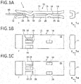
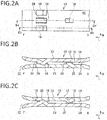
- the female contact 10 will be described with reference to FIGs. 1A to 1C and FIGs. 2A to 2C .
- the female contact 10 is integrally formed by folding a plate material at substantially 180 degrees.
- the female contact 10 includes a connection end 11 at a rear end and a pair of elastic beams including a first elastic arm 13 and a second elastic arm 23.
- the first elastic arm 13 and the second elastic arm 23 each extend from the connection end 11 toward a front end.
- the plate material forming the female contact 10 is made of a metal material having excellent electroconductivity and having high elasticity, such as a copper alloy, and is subjected to surface treatment such as plating treatment as necessary.
- the female contact 10 has spring property based on elasticity of each of the connection end 11, the first elastic arm 13, and the second elastic arm 23, and uses the spring property to sandwich the male contact 40 with a predetermined contact load.
- the female contact 10 has a mating opening 12 that is provided between the first elastic arm 13 and the second elastic arm 23 at the front end, and the mating male contact 40 is pushed in between the first elastic arm 13 and the second elastic arm 23 from the mating opening 12.
- an end receiving the male contact 40 is defined as a front F
- an opposite end on which the connection end 11 is provided is defined as a rear B.
- the front (F) and the rear (B) have relative relationship.
- a front-rear direction L, a width direction W, and a height direction H are defined as illustrated in FIGs. 1A to 1C .
- the front-rear direction L, the width direction W, and the height direction H are orthogonal to one another.
- the first elastic arm 13 and the second elastic arm 23 are substantially parallel to each other from the rear end connected to the connection end 11 toward the front end.
- the first elastic arm 13 includes an inner surface 14 facing the second elastic arm 23, and an outer surface 15 on a side opposite to the inner surface 14.
- the second elastic arm 23 includes an inner surface 24 facing the first elastic arm 13, and an outer surface 25 on a side opposite to the inner surface 24.
- the first elastic arm 13 includes the first actual contact point 16 and the first dummy contact points 18, 18 on the inner surface 14.
- the first actual contact point 16 and the first dummy contact points 18, 18 are formed integrally with the first elastic arm 13 through press processing in which a load is applied from the outer surface 15 toward the inner surface 14.
- the second actual contact points 26, 26 and the second dummy contact point 28 are formed in a similar manner.
- the first actual contact point 16 is a part of electrically connecting the female contact 10 and the male contact 40 in a mating completion state where the mating operation of the female contact 10 and the male contact 40 has been completed. Necessary power or an electrical signal flows between the female contact 10 and the male contact 40 through the first actual contact point 16.
- first dummy contact points 18, 18 come into contact with the male contact 40 from the start of the mating operation to immediately before completion of the mating operation of the female contact 10 and the male contact 40.
- the first actual contact point 16 does not come into contact with the male contact 40 while the first dummy contact points 18, 18 are in contact with the male contact 40.
- the contact of the first dummy contact points 18, 18 and the male contact 40 is released.
- the first dummy contact points 18, 18 do not perform electrical connection of the female contact 10 and the male contact 40 in the mating completion state.
- the first dummy contact points 18, 18 are provided nearer the front end than or forward of the first actual contact point 16.
- the male contact 40 comes into contact with the first dummy contact points 18, 18 before the first actual contact point 16.
- the first actual contact point 16 and the first dummy contact points 18, 18 are compared, the first actual contact point 16 has a smaller protrusion amount from the inner surface 14 toward the second elastic arm 23 than the first dummy contact points 18, 18.
- the first actual contact point 16 is provided only at one position, at a center of the female contact 10 in the width direction W.
- the two first dummy contact points 18, 18 are provided at symmetrical positions in the width direction W with a gap in the width direction W. Note that the number and the arrangement of the first actual contact point 16 and the first dummy contact point 18 are optional, and one or a plurality of first actual contact points 16 and one or a plurality of first dummy contact points 18, 18 may be provided.
- the second actual contact point 26 and the second dummy contact point 28 may be similarly provided.
- the first elastic arm 13 includes a first engagement portion or aperture 19 between the two first dummy contact points 18, 18 in the width direction W.
- the first engagement portion or aperture 19 penetrates through the top and bottom surfaces of the first elastic arm 13.
- a front end of the second dummy contact point 28 enters and is engaged with or positioned within the first engagement portion or aperture 19, which makes it possible to reduce the gap between the first elastic arm 13 and the second elastic arm 23. Note that this is based on the premise that no load is applied to the female contact 10.
- the second elastic arm 23 includes the second actual contact points 26, 26 and the second dummy contact point 28 on the inner surface 24 as illustrated in FIGs. 1A to 1C and FIGs. 2A to 2C .
- the second actual contact points 26, 26 are parts of electrically connecting the female contact 10 and the male contact 40 in the mating completion state where the mating operation of the female contact 10 and the male contact 40 has been completed. Necessary power or an electrical signal flows between the female contact 10 and the male contact 40 through the second actual contact points 26, 26.
- the second dummy contact point 28 is a part coming into contact with the male contact 40 from the start of the mating operation to immediately before completion of the mating operation of the female contact 10 and the male contact 40.
- the second actual contact points 26, 26 do not come into contact with the male contact 40 while the second dummy contact point 28 is in contact with the male contact 40.
- the contact of the second dummy contact point 28 and the male contact 40 is released.
- the second dummy contact point 28 does not perform electrical connection of the female contact 10 and the male contact 40 in the mating completion state, as with the first dummy contact points 18, 18.
- the second dummy contact point 28 is provided at a front end or forwardly of the second actual contact points 26, 26.
- the male contact 40 comes into contact with the second dummy contact point 28 before the second actual contact points 26, 26.
- each of the second actual contact points 26, 26 has a smaller protrusion amount from the inner surface 24 toward the first elastic arm 13 than the second dummy contact point 28.
- the two second actual contact points 26, 26 are provided at symmetrical positions in the width direction W with a gap in the width direction W of the female contact 10. Further, the second dummy contact point 28 is provided at the center in the width direction W.
- the protrusion amount of each of the second actual contact points 26, 26 from the inner surface 24 is equal to the protrusion amount of the first actual contact point 16 from the inner surface 14. Further, the protrusion amount of the second dummy contact point 28 from the inner surface 24 is equal to the protrusion amount of each of the first dummy contact points 18, 18 from the inner surface 14.
- the second elastic arm 23 includes second engagement portions or apertures 29 on both sides of the second dummy contact point 28 in the width direction W.
- Each of the second engagement portions 19 penetrates through the top and bottom surfaces of the second elastic arm 23.
- front ends of the first dummy contact points 18, 18 are respectively engaged with or positioned within the second engagement portions or apertures 29, which makes it possible to reduce the gap between the first elastic arm 13 and the second elastic arm 23, together with the first engagement portion 19.
- the first actual contact point 16 and the second actual contact points 26, 26 are provided at positions different from one another in the width direction W.
- the first dummy contact points 18, 18 and the second dummy contact point 28 are provided at positions different from one another in the width direction W. Accordingly, mutual interference between the first actual contact point 16 and the second actual contact points 26, 26 is avoided, and mutual interference between the first dummy contact points 18, 18 and the second dummy contact point 28 is avoided.
- the first actual contact point 16 and the second actual contact points 26, 26 of the female contact 10 cross with one another in the height direction H, and the first dummy contact points 18, 18 and the second dummy contact point 28 also cross with one another in the height direction H.
- the term cross used herein indicates that the first actual contact point 16 and the second actual contact points 26, 26 are overlapped with each other, and the first dummy contact points 18, 18 and the second dummy contact point 28 are overlapped with each other when the female contact 10 is viewed from the side.
- first elastic arm 13 includes the first engagement portion 19 and the second elastic arm 23 includes the second engagement portions 29.
- the first dummy contact points 18, 18 respectively enter the second engagement portions 29, and the front end of the second dummy contact point 28 is engaged with or enters the first engagement portion 19. Accordingly, it is possible to further reduce the gap between the first elastic arm 13 and the second elastic arm 23.
- first dummy contact points 18, 18 and the second dummy contact point 28 are disposed at symmetrical positions in the width direction W
- first actual contact point 16 and the second actual contact points 26, 26 are disposed at symmetrical positions in the width direction W.
- first dummy contact points 18, 18 and the second dummy contact point 28 are provided at the same position in the front-rear direction L.
- the male contact 40 will be described with reference to FIGs. 3A to 3C .
- the male contact 40 is a flat plate-like member having a rectangular planar shape.
- the male contact 40 is made of a metal material similar to that of the female contact 10; however, the male contact 40 may be made of a metal material having low elasticity.
- a plate thickness of the male contact 40 is selected within the range of 1 mm or less, and is preferably 0.5 mm or less, more preferably 0.2 mm or less, and most preferably 0.1 mm or less within the range.
- the first actual contact point 16 and the second actual contact points 26, 26 of the female contact 10 come into contact with a top surface 42 and a bottom surface 43 of the male contact 40, which results in electrical connection with the female contact 10.
- an end to be inserted into the female contact 10 is defined as a front F and an opposite end is defined as a rear B.
- the front F and the rear B have relative relationship.
- the width direction W and the front-rear direction L are defined as illustrated in FIGs. 3A to 3C .
- the male contact 40 includes a main body 41 made of a metal material, and a third engagement portion or aperture 45 that penetrates through the top and bottom surfaces of the main body 41.
- the male contact 40 When the male contact 40 is pushed into a position completely mated with the female contact 10 and is put into the mating completion state, the first dummy contact points 18, 18 of the first elastic arm 13 are engaged with the third engagement portion 45 from the top surface 42 toward the bottom surface 43 of the main body 41, and the second dummy contact point 28 of the second elastic arm 23 is engaged with the third engagement portion 45 from the bottom surface 43 toward the top surface 42 of the main body 41.
- the third engagement portion 45 is provided in the region of the front-rear direction L with which the first dummy contact points 18, 18 and the second dummy contact point 28 are engaged, in the state where the female contact 10 and the male contact 40 have been completely mated with each other.
- top surface 42 and the bottom surface 43 of the main body 41 are not uniquely defined.
- the surface facing the first elastic arm 13 is referred to as the top surface 42
- the surface facing the second elastic arm 23 is referred to as the bottom surface 43.
- the third engagement portion 45 is provided in the region corresponding to the first dummy contact points 18, 18 and the second dummy contact point 28 in the state where the female contact 10 and the male contact 40 have been completely mated with each other.
- the third engagement portion 45 may be provided as an extended wide region including the corresponding region as illustrated in FIGs. 3A and 3B , or a plurality of, for example, three third engagement portions or apertures 45 may be provided in limited regions respectively corresponding to the first dummy contact points 18, 18 and the second dummy contact point 28 as illustrated in FIG. 3C .
- the male contact 40 includes burrs that are formed at a peripheral edge including a front end because the male contact 40 is fabricated by stamping the plate material. On the other hand, the burrs remain in the peripheral edge because the male contact 40 has a small thickness and thus it is difficult to perform taper processing on the front end. The burrs may come into contact with the first actual contact point 16 and the second actual contact points 26, 26 of the female contact 10 to abnormally abrade the first actual contact point 16 and the second actual contact points 26, 26 when the male contact 40 is mated with the female contact 10.
- the male contact 40 is positioned with respect to or adjacent to the mating opening 12 that is provided on the front end of the first elastic arm 13 and the second elastic arm 23, and the male contact 40 is then pushed into the female contact 10.
- the male contact 40 When the male contact 40 is pushed in toward the mating completion position, the male contact 40 passes between the first actual contact point 16 of the first elastic arm 13 and the second actual contact points 26, 26 of the second elastic arm 23 as illustrated in FIG. 4B .
- the distance d still exceeds the thickness t even when the male contact 40 is pushed in because the male contact 40 has constant thickness. Therefore, the front end of the male contact 40 does not come into contact with and is apart from the first actual contact point 16 and the second actual contact points 26, 26 when the front end passes between the first actual contact point 16 and the second actual contact points 26, 26. Accordingly, even if the burrs remain at the front end of the male contact 40, the front end having the burrs does not come into contact with and abrade the first actual contact point 16 and the second actual contact points 26, 26.
- the first dummy contact points 18, 18 of the first elastic arm 13 and the second dummy contact point 28 of the second elastic arm 23 are inserted into the third engagement portion 45 of the male contact 40 as illustrated in FIG. 4C .
- the first elastic arm 13 and the second elastic arm 23 are released from support by the male contact 40, and are elastically returned to reduce the gap between the first elastic arm 13 and the second elastic arm 23 that has been pushingly expanded.
- the first actual contact point 16 and the second actual contact points 26, 26 respectively come into contact with the top surface 42 and the bottom surface 43 of the male contact 40, and a contact load, resistant to vibration, is applied to the male contact 40 through the first actual contact point 16 and the second actual contact points 26, 26.
- the mating structure 1 makes it possible to prevent the front end of the male contact 40 from coming into contact with the first actual contact point 16 and the second actual contact points 26, 26 even in the case of a thin male contact 40, the front end of which can not easily be formed with a taper. This prevents abnormal abrasion of the first actual contact point 16 and the second actual contact points 26, 26.
- the mating structure 1 it is unnecessary to consider abrasion due to the contact of the front end of the male contact 40 with the first actual contact point 16 and the second actual contact points 26, 26. This makes it possible to secure high contact load by the first elastic arm 13 and the second elastic arm 23, and to achieve stable electrical connection of the female contact 10 and the male contact 40.
- the mating structure 1 includes the plurality of first dummy contact points 18, 18 and the second dummy contact point 28 in the width direction W. Therefore, it is possible to mate the male contact 40 with the female contact 10 while stabilizing the attitude of the male contact 40 in the mating process of the female contact 10 and the male contact 40.
- the first dummy contact points 18, 18 and the second dummy contact point 28 are disposed symmetrically in the width direction W, which makes it possible to further stabilize the attitude of the male contact 40 in the mating process.
- the mating structure 1 of the present embodiment includes the first actual contact point 16 and the plurality of second actual contact points 26, 26, and the first actual contact point 16 and the second actual contact points 26, 26 are disposed at the symmetrical positions in the width direction W. Therefore, it is possible to balance the force holding the male contact 40 in the width direction W. As a result, the mating structure 1 makes it possible to bring an amplitude when receiving vibration, close to uniform in the width direction W, thereby achieving high vibration resistance.
- the female contact 10 it is possible to reduce the gap between the first elastic arm 13 and the second elastic arm 23 in an unloaded state by providing the first actual contact point 16 and the second actual contact points 26, 26 at the positions different from one another in the width direction W and providing the first dummy contact points 18, 18 and the second dummy contact point 28 at the positions different from one another in the width direction W, etc.
- the male contact 40 is mated with the female contact 10
- the female contact 10 makes it possible to increase the contact load that is applied to the male contact 40 through the first actual contact point 16 and the second actual contact points 26, 26.
- the first dummy contact points 18, 18 and the second dummy contact point 28 cross with one another in the height direction. Therefore, when the male contact 40 is inserted between the first dummy contact points 18, 18 and the second dummy contact point 28, the male contact 40 pushingly expands the gap between the first elastic arm 13 and the second elastic arm 23. This is advantageous as it reliably separates the first actual contact point 16 and the second actual contact points 26, 26 from the male contact 40 until immediately before mating completion.
- the mating structure 1 As schematically illustrated in FIG. 5A , in the mating structure 1 according to the present embodiment, the example in which the protrusion amount of each of the first dummy contact points 18, 18 and the second dummy contact point 28 is larger than the protrusion amount of each of the first actual contact point 16 and the second actual contact points 26, 26 has been described, based on the premise that the first elastic arm 13 and the second elastic arm 23 are wholly parallel to each other.
- the present invention is not limited to such a configuration.
- the protrusion amount in the present invention is specified at a position of a top of each of the first actual contact point 16, the second actual contact points 26, 26, the first dummy contact points 18, 18, and the second dummy contact point 28, in the unloaded state where the male contact 40 is not mated with the female contact 10.
- the first dummy contact points 18, 18 and the second dummy contact point 28 are disposed at the different positions that are shifted from one another in the width direction W; however, the present invention is not limited thereto.
- the first dummy contact points 18, 18 and the second dummy contact point 28 may be provided at the same position in the width direction W.
- the first actual contact point 16 and the second actual contact points 26, 26 may be similarly provided.
- the first dummy contact points 18, 18 and the second dummy contact point 28 are provided at the same position in the front-rear direction L; however, the present invention is not limited thereto.
- the first dummy contact points 18, 18 of the first elastic arm 13 and the second dummy contact point 28 of the second elastic arm 23 may be disposed at different positions that are shifted from one another in the front-rear direction L.
- third engagement portions 45A, 45B, and 45C each having a bottom may be provided in the main body 41.
- the third engagement portions 45A and 45C respectively correspond to the first dummy contact points 18, 18 of the first elastic arm 13, and are recessed from the top surface 42 toward the bottom surface 43 of the main body 41.
- the third engagement portion 45B corresponds to the second dummy contact point 28 of the second elastic arm 23, and is recessed from the bottom surface 43 toward the top surface 42 of the main body 41.
- first elastic arm 13 and the second elastic arm 23 in the present embodiment are coupled to each other at the respective rear ends; however, the two arms 13 and 23 may be coupled to each other at the respective sides.
Landscapes
- Details Of Connecting Devices For Male And Female Coupling (AREA)
- Coupling Device And Connection With Printed Circuit (AREA)
Abstract
Description
- The present invention relates to a female contact that is mated with a plate-like male contact by sandwiching the male contact, and in particular to a female contact that makes it possible to reduce abrasion of a contact point by the male contact.
- An electrical connector that includes a plate-like male contact and a female contact for example for outside use, is described in
JP 6-86268 U -
JP 6-86268 U JP 6-86268 U - Typically, in the electrical connector of this kind, a front end of the male contact to be inserted into the female contact first is formed with a tapered shape in order to suppress abrasion of the contact point of the female contact caused by burrs of a front end edge of the male contact. When a plate thickness of the male contact is thin, for example, about 1 mm, however, it is difficult to achieve such a taper. To suppress abrasion when the male contact comes into contact with the contact point of the female contact, it is possible to weaken the force of the female contact sandwiching the male contact to reduce contact load. When the contact load is small, however, it is not possible to achieve stable electrical connection, for example, in an environment in which there is vibration.
- In the female contact 60 disclosed in
JP 6-86268 U - Accordingly, an object of the present invention is to provide the female contact that makes it possible to suppress abrasion of the contact point of the female contact and to secure a necessary contact load with the male contact, even in a case of the male contact having a small plate thickness.
- In addition, an object of the present invention is to provide a mating structure including the female contact and the male contact.
- A female contact according to the present invention includes a first elastic arm and a second elastic arm that extend from a rear end side toward a front end side and are connected to each other.
- The first elastic arm according to the present invention includes a first dummy contact point provided on the front end side, and a first actual contact point that is provided rearward of the first dummy contact point and has a smaller protrusion amount than the first dummy contact point. The second elastic arm includes a second dummy contact point provided on the front end side, and a second actual contact point that is provided rearward of the second dummy contact point and has a smaller protrusion amount than the second dummy contact point.
- According to the female contact of the present invention, the first dummy contact point and the second dummy contact point each having the large protrusion amount come into contact with the male contact until a front end of the male contact passes through the first actual contact point and the second actual contact point; however, it is possible to separate the first actual contact point and the second actual contact point each having the small protrusion amount from the male contact without contact. Therefore, according to the present invention, even in the case of the male contact having the small plate thickness, it is possible to suppress abrasion of the first actual contact point and the second actual contact point of the female contact that are contact points performing electrical connection. In addition, according to the present invention, it is unnecessary to consider abrasion of the contact point of the female contact, which makes it possible to secure the sufficient contact load with respect to the male contact.
- In the female contact according to the present invention, the first dummy contact point provided on the first elastic arm and the second dummy contact point provided on the second elastic arm may be provided at positions different from each other in a width direction that is orthogonal to a front-rear direction, and the first actual contact point provided on the first elastic arm and the second actual contact point provided on the second elastic arm may be provided at positions different from each other in the width direction.
- In the female contact according to the present invention, the first dummy contact point and the second dummy contact point may be provided to cross with each other in a height direction in which the first elastic arm and the second elastic arm face each other, and the first actual contact point and the second actual contact point may be provided to cross with each other in the height direction.
- In the female contact according to the present invention, the first elastic arm may include a first engagement portion with which the second dummy contact point is engaged, and the second elastic arm may include a second engagement portion with which the first dummy contact point is engaged.
- In the female contact according to the present invention, the first dummy contact point and the second dummy contact point may be disposed symmetrically in the width direction that is orthogonal to the front-rear direction, and the first actual contact point and the second actual contact point may be disposed symmetrically in the width direction.
- In the female contact according to the present invention, the first dummy contact point and the second dummy contact point may be provided at the same position in the front-rear direction.
- In the female contact according to the present invention, in a case where the first elastic arm and the second elastic arm are parallel to each other, the first dummy contact point may be made larger in protrusion amount from the first elastic arm than the first actual contact point, and the second dummy contact point may be made larger in protrusion amount from the second elastic arm than the second actual contact point.
- The present invention proposes a mating structure of contacts that includes a female contact including a first elastic arm and a second elastic arm that extend from a rear end side toward a front end side and are connected to each other, and a plate-like male contact that is sandwiched between the first elastic arm and the second elastic arm.
- The mating structure according to the present invention adopts any of the above-described female contacts, and the male contact includes a third engagement portion with which the first dummy contact point and the second dummy contact point of the female contact are engaged in a state where the male contact is completely mated with the female contact.
- According to the female contact of the present invention, it is possible to suppress abrasion of the contact point of the female contact and to secure a sufficient contact load to the male contact even in a case of the male contact having a small plate thickness.
-
-
FIGs. 1A to 1C each illustrate a female contact according to an embodiment of the present invention,FIG. 1A being a side view,FIG. 1B being a top plan view, andFIG. 1C being a bottom view; -
FIGs. 2A to 2C each illustrate the female contact ofFIGs. 1A to 1C ,FIG. 2A being a top plan view,FIG. 2B being a cross-sectional view taken along a line IIb-IIb ofFIG. 2A, and FIG. 2C being a cross-sectional view taken along a line IIc-IIc ofFIG. 2A ; -
FIGs. 3A to 3C each illustrate a male contact according to the embodiment of the present invention,FIG. 3A being a top plan view,FIG. 3B being a cross-sectional view taken along a line IIIb-IIIb ofFIG. 3A, and FIG. 3C being a plan view of a male contact according to a modification; -
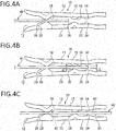
FIGs. 4A to 4C are side views each illustrating a mating process of the female contact and the male contact according to the present embodiment; -
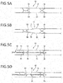
FIGs. 5A to 5D are diagrams to explain modifications of the female contact of the present embodiment,FIG. 5A being a diagram illustrating the present embodiment in a simplified manner, andFIGs. 5B to 5D being diagrams illustrating the modifications; and -
FIGs. 6A to 6C each illustrate a modification of the male contact of the present embodiment,FIG. 6A being a top plan view,FIG. 6B being a cross-sectional view taken along a line VIb-VIb ofFIG. 6A, and FIG. 6C being a cross-sectional view taken along a line VIc-VIc ofFIG. 6A . - An embodiment of the present invention is described below with reference to accompanying drawings.
- As illustrated in
FIG. 1A andFIG. 4C , a contact pair or mating structure 1 of contacts according to the present embodiment includes afemale contact 10 and a plate-likemale contact 40 that is sandwiched by thefemale contact 10. Thefemale contact 10 has a new configuration including a dummy contact point, which allows the mating structure 1 to suppress abrasion of the contact point of thefemale contact 10 and securing a sufficient contact load with respect to themale contact 40 even when themale contact 40 has a small plate thickness. - In the following description, the forms of the mating structure 1, the
female contact 10, and themale contact 40 are described in order, and then the interaction between thefemale contact 10 and themale contact 40 is described. - As illustrated in
FIG. 1A andFIG. 4C , in the mating structure 1, themale contact 40 is sandwiched from top and bottom surfaces by thefemale contact 10, which results in electrical connection of thefemale contact 10 and themale contact 40. The electrical connection is achieved by contact of a firstactual contact point 16 and second actual contact points 26, 26 of thefemale contact 10 with themale contact 40. The mating structure 1 of the present embodiment is characterized in that thefemale contact 10 includes first dummy contact points 18, 18 and a seconddummy contact point 28, in addition to the firstactual contact point 16 and the second actual contact points 26, 26. - The
female contact 10 will be described with reference toFIGs. 1A to 1C andFIGs. 2A to 2C . Thefemale contact 10 is integrally formed by folding a plate material at substantially 180 degrees. As illustrated inFIGs. 1A to 1C , thefemale contact 10 includes aconnection end 11 at a rear end and a pair of elastic beams including a firstelastic arm 13 and a secondelastic arm 23. The firstelastic arm 13 and the secondelastic arm 23 each extend from theconnection end 11 toward a front end. The plate material forming thefemale contact 10 is made of a metal material having excellent electroconductivity and having high elasticity, such as a copper alloy, and is subjected to surface treatment such as plating treatment as necessary. - The
female contact 10 has spring property based on elasticity of each of theconnection end 11, the firstelastic arm 13, and the secondelastic arm 23, and uses the spring property to sandwich themale contact 40 with a predetermined contact load. - The
female contact 10 has amating opening 12 that is provided between the firstelastic arm 13 and the secondelastic arm 23 at the front end, and themating male contact 40 is pushed in between the firstelastic arm 13 and the secondelastic arm 23 from themating opening 12. - Note that in the following description in the
female contact 10, an end receiving themale contact 40 is defined as a front F, and an opposite end on which theconnection end 11 is provided is defined as a rear B. The front (F) and the rear (B) have relative relationship. - Further, in the
female contact 10, a front-rear direction L, a width direction W, and a height direction H are defined as illustrated inFIGs. 1A to 1C . The front-rear direction L, the width direction W, and the height direction H are orthogonal to one another. - As illustrated in
FIGs. 1A to 1C andFIGs. 2A to 2C , the firstelastic arm 13 and the secondelastic arm 23 are substantially parallel to each other from the rear end connected to theconnection end 11 toward the front end. The firstelastic arm 13 includes aninner surface 14 facing the secondelastic arm 23, and anouter surface 15 on a side opposite to theinner surface 14. In addition, the secondelastic arm 23 includes aninner surface 24 facing the firstelastic arm 13, and anouter surface 25 on a side opposite to theinner surface 24. - As illustrated in
FIGs. 1A to 1C andFIGs. 2A to 2C , the firstelastic arm 13 includes the firstactual contact point 16 and the first dummy contact points 18, 18 on theinner surface 14. - The first
actual contact point 16 and the first dummy contact points 18, 18 are formed integrally with the firstelastic arm 13 through press processing in which a load is applied from theouter surface 15 toward theinner surface 14. The second actual contact points 26, 26 and the seconddummy contact point 28 are formed in a similar manner. - The first
actual contact point 16 is a part of electrically connecting thefemale contact 10 and themale contact 40 in a mating completion state where the mating operation of thefemale contact 10 and themale contact 40 has been completed. Necessary power or an electrical signal flows between thefemale contact 10 and themale contact 40 through the firstactual contact point 16. - Further, the first dummy contact points 18, 18 come into contact with the
male contact 40 from the start of the mating operation to immediately before completion of the mating operation of thefemale contact 10 and themale contact 40. The firstactual contact point 16 does not come into contact with themale contact 40 while the first dummy contact points 18, 18 are in contact with themale contact 40. In contrast, when the firstactual contact point 16 comes into contact with themale contact 40, the contact of the first dummy contact points 18, 18 and themale contact 40 is released. As described above, the first dummy contact points 18, 18 do not perform electrical connection of thefemale contact 10 and themale contact 40 in the mating completion state. - As illustrated in
FIG. 1A , the first dummy contact points 18, 18 are provided nearer the front end than or forward of the firstactual contact point 16. When themale contact 40 is inserted between the firstelastic arm 13 and the secondelastic arm 23, themale contact 40 comes into contact with the first dummy contact points 18, 18 before the firstactual contact point 16. - When the first
actual contact point 16 and the first dummy contact points 18, 18 are compared, the firstactual contact point 16 has a smaller protrusion amount from theinner surface 14 toward the secondelastic arm 23 than the first dummy contact points 18, 18. - The first
actual contact point 16 is provided only at one position, at a center of thefemale contact 10 in the width direction W. In addition, the two first dummy contact points 18, 18 are provided at symmetrical positions in the width direction W with a gap in the width direction W. Note that the number and the arrangement of the firstactual contact point 16 and the firstdummy contact point 18 are optional, and one or a plurality of first actual contact points 16 and one or a plurality of first dummy contact points 18, 18 may be provided. The secondactual contact point 26 and the seconddummy contact point 28 may be similarly provided. - As illustrated in
FIG. 1B , the firstelastic arm 13 includes a first engagement portion oraperture 19 between the two first dummy contact points 18, 18 in the width direction W. The first engagement portion oraperture 19 penetrates through the top and bottom surfaces of the firstelastic arm 13. When thefirst engagement portion 19 is provided, a front end of the seconddummy contact point 28 enters and is engaged with or positioned within the first engagement portion oraperture 19, which makes it possible to reduce the gap between the firstelastic arm 13 and the secondelastic arm 23. Note that this is based on the premise that no load is applied to thefemale contact 10. - Next, the second
elastic arm 23 includes the second actual contact points 26, 26 and the seconddummy contact point 28 on theinner surface 24 as illustrated inFIGs. 1A to 1C andFIGs. 2A to 2C . - The second actual contact points 26, 26 are parts of electrically connecting the
female contact 10 and themale contact 40 in the mating completion state where the mating operation of thefemale contact 10 and themale contact 40 has been completed. Necessary power or an electrical signal flows between thefemale contact 10 and themale contact 40 through the second actual contact points 26, 26. - Further, the second
dummy contact point 28 is a part coming into contact with themale contact 40 from the start of the mating operation to immediately before completion of the mating operation of thefemale contact 10 and themale contact 40. The second actual contact points 26, 26 do not come into contact with themale contact 40 while the seconddummy contact point 28 is in contact with themale contact 40. In contrast, when the second actual contact points 26, 26 come into contact with themale contact 40, the contact of the seconddummy contact point 28 and themale contact 40 is released. As described above, the seconddummy contact point 28 does not perform electrical connection of thefemale contact 10 and themale contact 40 in the mating completion state, as with the first dummy contact points 18, 18. - As illustrated in
FIG. 1A , the seconddummy contact point 28 is provided at a front end or forwardly of the second actual contact points 26, 26. When themale contact 40 is inserted between the firstelastic arm 13 and the secondelastic arm 23, themale contact 40 comes into contact with the seconddummy contact point 28 before the second actual contact points 26, 26. - When the second actual contact points 26, 26 and the second
dummy contact point 28 are compared, each of the second actual contact points 26, 26 has a smaller protrusion amount from theinner surface 24 toward the firstelastic arm 13 than the seconddummy contact point 28. - The two second actual contact points 26, 26 are provided at symmetrical positions in the width direction W with a gap in the width direction W of the
female contact 10. Further, the seconddummy contact point 28 is provided at the center in the width direction W. - The protrusion amount of each of the second actual contact points 26, 26 from the
inner surface 24 is equal to the protrusion amount of the firstactual contact point 16 from theinner surface 14. Further, the protrusion amount of the seconddummy contact point 28 from theinner surface 24 is equal to the protrusion amount of each of the first dummy contact points 18, 18 from theinner surface 14. - As illustrated in
FIG. 1C , the secondelastic arm 23 includes second engagement portions orapertures 29 on both sides of the seconddummy contact point 28 in the width direction W. Each of thesecond engagement portions 19 penetrates through the top and bottom surfaces of the secondelastic arm 23. When thesecond engagement portions 29 are provided, front ends of the first dummy contact points 18, 18 are respectively engaged with or positioned within the second engagement portions orapertures 29, which makes it possible to reduce the gap between the firstelastic arm 13 and the secondelastic arm 23, together with thefirst engagement portion 19. - Next, the arrangement of the first
actual contact point 16, the second actual contact points 26, 26, the first dummy contact points 18, 18, and the seconddummy contact point 28 is described with reference toFIGs. 1A to 1C andFIGs. 2A to 2C . - The first
actual contact point 16 and the second actual contact points 26, 26 are provided at positions different from one another in the width direction W. The first dummy contact points 18, 18 and the seconddummy contact point 28 are provided at positions different from one another in the width direction W. Accordingly, mutual interference between the firstactual contact point 16 and the second actual contact points 26, 26 is avoided, and mutual interference between the first dummy contact points 18, 18 and the seconddummy contact point 28 is avoided. - In particular, as illustrated in
FIG. 1A andFIGs. 2B and 2C , the firstactual contact point 16 and the second actual contact points 26, 26 of thefemale contact 10 cross with one another in the height direction H, and the first dummy contact points 18, 18 and the seconddummy contact point 28 also cross with one another in the height direction H. This makes it possible to reduce the gap between the firstelastic arm 13 and the secondelastic arm 23. Note that the term cross used herein indicates that the firstactual contact point 16 and the second actual contact points 26, 26 are overlapped with each other, and the first dummy contact points 18, 18 and the seconddummy contact point 28 are overlapped with each other when thefemale contact 10 is viewed from the side. - In addition, the first
elastic arm 13 includes thefirst engagement portion 19 and the secondelastic arm 23 includes thesecond engagement portions 29. The first dummy contact points 18, 18 respectively enter thesecond engagement portions 29, and the front end of the seconddummy contact point 28 is engaged with or enters thefirst engagement portion 19. Accordingly, it is possible to further reduce the gap between the firstelastic arm 13 and the secondelastic arm 23. - Moreover, the first dummy contact points 18, 18 and the second
dummy contact point 28 are disposed at symmetrical positions in the width direction W, and the firstactual contact point 16 and the second actual contact points 26, 26 are disposed at symmetrical positions in the width direction W. - Furthermore, the first dummy contact points 18, 18 and the second
dummy contact point 28 are provided at the same position in the front-rear direction L. - The
male contact 40 will be described with reference toFIGs. 3A to 3C . Next, as illustrated inFIGs. 3A to 3C , themale contact 40 is a flat plate-like member having a rectangular planar shape. Themale contact 40 is made of a metal material similar to that of thefemale contact 10; however, themale contact 40 may be made of a metal material having low elasticity. A plate thickness of themale contact 40 is selected within the range of 1 mm or less, and is preferably 0.5 mm or less, more preferably 0.2 mm or less, and most preferably 0.1 mm or less within the range. The firstactual contact point 16 and the second actual contact points 26, 26 of thefemale contact 10 come into contact with atop surface 42 and abottom surface 43 of themale contact 40, which results in electrical connection with thefemale contact 10. - In the
male contact 40, the following description is given while an end to be inserted into thefemale contact 10 is defined as a front F and an opposite end is defined as a rear B. The front F and the rear B have relative relationship. - In addition, in the
male contact 40, the width direction W and the front-rear direction L are defined as illustrated inFIGs. 3A to 3C . - As illustrated in
FIGs. 3A and 3B , themale contact 40 includes amain body 41 made of a metal material, and a third engagement portion oraperture 45 that penetrates through the top and bottom surfaces of themain body 41. - When the
male contact 40 is pushed into a position completely mated with thefemale contact 10 and is put into the mating completion state, the first dummy contact points 18, 18 of the firstelastic arm 13 are engaged with thethird engagement portion 45 from thetop surface 42 toward thebottom surface 43 of themain body 41, and the seconddummy contact point 28 of the secondelastic arm 23 is engaged with thethird engagement portion 45 from thebottom surface 43 toward thetop surface 42 of themain body 41. Thethird engagement portion 45 is provided in the region of the front-rear direction L with which the first dummy contact points 18, 18 and the seconddummy contact point 28 are engaged, in the state where thefemale contact 10 and themale contact 40 have been completely mated with each other. - Note that the
top surface 42 and thebottom surface 43 of themain body 41 are not uniquely defined. In the present embodiment, for convenience, the surface facing the firstelastic arm 13 is referred to as thetop surface 42, and the surface facing the secondelastic arm 23 is referred to as thebottom surface 43. - As described above, the
third engagement portion 45 is provided in the region corresponding to the first dummy contact points 18, 18 and the seconddummy contact point 28 in the state where thefemale contact 10 and themale contact 40 have been completely mated with each other. Thethird engagement portion 45 may be provided as an extended wide region including the corresponding region as illustrated inFIGs. 3A and 3B , or a plurality of, for example, three third engagement portions orapertures 45 may be provided in limited regions respectively corresponding to the first dummy contact points 18, 18 and the seconddummy contact point 28 as illustrated inFIG. 3C . - The
male contact 40 includes burrs that are formed at a peripheral edge including a front end because themale contact 40 is fabricated by stamping the plate material. On the other hand, the burrs remain in the peripheral edge because themale contact 40 has a small thickness and thus it is difficult to perform taper processing on the front end. The burrs may come into contact with the firstactual contact point 16 and the second actual contact points 26, 26 of thefemale contact 10 to abnormally abrade the firstactual contact point 16 and the second actual contact points 26, 26 when themale contact 40 is mated with thefemale contact 10. In the mating structure 1 according to the present embodiment, however, it is possible to prevent the front end of themale contact 40 from coming into contact with the firstactual contact point 16 and the second actual contact points 26, 26 when the front end of themale contact 40 passes through the firstactual contact point 16 and the second actual contact points 26, 26. - Next, a procedure of mating the
female contact 10 and themale contact 40 with each other is described with reference toFIG. 1A andFIG. 4C . - First, as illustrated in
FIG. 1A , themale contact 40 is positioned with respect to or adjacent to themating opening 12 that is provided on the front end of the firstelastic arm 13 and the secondelastic arm 23, and themale contact 40 is then pushed into thefemale contact 10. - When the
male contact 40 is inserted between the first dummy contact points 18, 18 and the seconddummy contact point 28 as illustrated inFIG. 4C , the mutual gap between the firstelastic arm 13 and the secondelastic arm 23 is expanded. At this time, the first dummy contact points 18, 18 and the seconddummy contact point 28 come into contact with themale contact 40, and a distance d between the firstactual contact point 16 and the second actual contact points 26, 26 exceeds a thickness t of themale contact 40 as illustrated inFIG. 4B . - When the
male contact 40 is pushed in toward the mating completion position, themale contact 40 passes between the firstactual contact point 16 of the firstelastic arm 13 and the second actual contact points 26, 26 of the secondelastic arm 23 as illustrated inFIG. 4B . The distance d still exceeds the thickness t even when themale contact 40 is pushed in because themale contact 40 has constant thickness. Therefore, the front end of themale contact 40 does not come into contact with and is apart from the firstactual contact point 16 and the second actual contact points 26, 26 when the front end passes between the firstactual contact point 16 and the second actual contact points 26, 26. Accordingly, even if the burrs remain at the front end of themale contact 40, the front end having the burrs does not come into contact with and abrade the firstactual contact point 16 and the second actual contact points 26, 26. - When the
male contact 40 is pushed into the mating completion position, the first dummy contact points 18, 18 of the firstelastic arm 13 and the seconddummy contact point 28 of the secondelastic arm 23 are inserted into thethird engagement portion 45 of themale contact 40 as illustrated inFIG. 4C . As a result, the firstelastic arm 13 and the secondelastic arm 23 are released from support by themale contact 40, and are elastically returned to reduce the gap between the firstelastic arm 13 and the secondelastic arm 23 that has been pushingly expanded. Accordingly, the firstactual contact point 16 and the second actual contact points 26, 26 respectively come into contact with thetop surface 42 and thebottom surface 43 of themale contact 40, and a contact load, resistant to vibration, is applied to themale contact 40 through the firstactual contact point 16 and the second actual contact points 26, 26. - Action and effects achieved by the present embodiment are described below.
- In the mating structure 1 according to the present embodiment, when the front end of the
male contact 40 passes through the firstactual contact point 16 and the second actual contact points 26, 26 and the mating completion state is established, the firstactual contact point 16 and the second actual contact points 26, 26 come into contact with themale contact 40. Accordingly, the mating structure 1 makes it possible to prevent the front end of themale contact 40 from coming into contact with the firstactual contact point 16 and the second actual contact points 26, 26 even in the case of a thinmale contact 40, the front end of which can not easily be formed with a taper. This prevents abnormal abrasion of the firstactual contact point 16 and the second actual contact points 26, 26. - Further, according to the mating structure 1, it is unnecessary to consider abrasion due to the contact of the front end of the
male contact 40 with the firstactual contact point 16 and the second actual contact points 26, 26. This makes it possible to secure high contact load by the firstelastic arm 13 and the secondelastic arm 23, and to achieve stable electrical connection of thefemale contact 10 and themale contact 40. - Next, the mating structure 1 according to the present embodiment includes the plurality of first dummy contact points 18, 18 and the second
dummy contact point 28 in the width direction W. Therefore, it is possible to mate themale contact 40 with thefemale contact 10 while stabilizing the attitude of themale contact 40 in the mating process of thefemale contact 10 and themale contact 40. In particular, in the present embodiment, the first dummy contact points 18, 18 and the seconddummy contact point 28 are disposed symmetrically in the width direction W, which makes it possible to further stabilize the attitude of themale contact 40 in the mating process. - Moreover, the mating structure 1 of the present embodiment includes the first
actual contact point 16 and the plurality of second actual contact points 26, 26, and the firstactual contact point 16 and the second actual contact points 26, 26 are disposed at the symmetrical positions in the width direction W. Therefore, it is possible to balance the force holding themale contact 40 in the width direction W. As a result, the mating structure 1 makes it possible to bring an amplitude when receiving vibration, close to uniform in the width direction W, thereby achieving high vibration resistance. - Furthermore, in the
female contact 10 according to the present embodiment, it is possible to reduce the gap between the firstelastic arm 13 and the secondelastic arm 23 in an unloaded state by providing the firstactual contact point 16 and the second actual contact points 26, 26 at the positions different from one another in the width direction W and providing the first dummy contact points 18, 18 and the seconddummy contact point 28 at the positions different from one another in the width direction W, etc. When themale contact 40 is mated with thefemale contact 10, it is possible to increase the expanded dimension of the firstelastic arm 13 and the secondelastic arm 23. This makes it possible to increase elastic forces experienced by thefemale contact 10. Accordingly, thefemale contact 10 makes it possible to increase the contact load that is applied to themale contact 40 through the firstactual contact point 16 and the second actual contact points 26, 26. - In addition, in the
female contact 10 according to the present invention, the first dummy contact points 18, 18 and the seconddummy contact point 28 cross with one another in the height direction. Therefore, when themale contact 40 is inserted between the first dummy contact points 18, 18 and the seconddummy contact point 28, themale contact 40 pushingly expands the gap between the firstelastic arm 13 and the secondelastic arm 23. This is advantageous as it reliably separates the firstactual contact point 16 and the second actual contact points 26, 26 from themale contact 40 until immediately before mating completion. - Although the preferred embodiment of the present invention has been described hereinbefore, the configurations described in the above-described embodiment may be selected or may be appropriately modified without departing from the scope of the present invention.
- As schematically illustrated in
FIG. 5A , in the mating structure 1 according to the present embodiment, the example in which the protrusion amount of each of the first dummy contact points 18, 18 and the seconddummy contact point 28 is larger than the protrusion amount of each of the firstactual contact point 16 and the second actual contact points 26, 26 has been described, based on the premise that the firstelastic arm 13 and the secondelastic arm 23 are wholly parallel to each other. The present invention, however, is not limited to such a configuration. - For example, as illustrated in
FIG. 5B , wheninclination parts elastic arm 13 and the secondelastic arm 23, it is possible to make the protrusion amount of each of the first dummy contact points 18, 18 and the seconddummy contact point 28 equivalent to or lower than the protrusion amount of each of the firstactual contact point 16 and the second actual contact points 26, 26. In other words, the protrusion amount in the present invention is specified at a position of a top of each of the firstactual contact point 16, the second actual contact points 26, 26, the first dummy contact points 18, 18, and the seconddummy contact point 28, in the unloaded state where themale contact 40 is not mated with thefemale contact 10. - Incidentally, processing is easily performed in the case where the first
elastic arm 13 and the secondelastic arm 23 are parallel to each other, as compared with the case of providing theinclination parts - Moreover, as illustrated in
FIGs. 1A to 1C andFIGs. 2A to 2C , in the mating structure 1 according to the present embodiment, the first dummy contact points 18, 18 and the seconddummy contact point 28 are disposed at the different positions that are shifted from one another in the width direction W; however, the present invention is not limited thereto. For example, as illustrated inFIG. 5C , the first dummy contact points 18, 18 and the seconddummy contact point 28 may be provided at the same position in the width direction W. The firstactual contact point 16 and the second actual contact points 26, 26 may be similarly provided. - Further, in the mating structure 1 according to the present embodiment, the first dummy contact points 18, 18 and the second
dummy contact point 28 are provided at the same position in the front-rear direction L; however, the present invention is not limited thereto. For example, as illustrated inFIG. 5D , the first dummy contact points 18, 18 of the firstelastic arm 13 and the seconddummy contact point 28 of the secondelastic arm 23 may be disposed at different positions that are shifted from one another in the front-rear direction L. - Furthermore, in the mating structure 1 according to the present embodiment, the example in which, in the mating completion state, the first dummy contact points 18, 18 and the second
dummy contact point 28 are engaged with thethird engagement portion 45 that penetrates through the top and bottom surfaces of themain body 41 has been described; however, the present invention is not limited thereto. For example, as illustrated inFIGs. 6A to 6C ,third engagement portions main body 41. Thethird engagement portions 45A and 45C respectively correspond to the first dummy contact points 18, 18 of the firstelastic arm 13, and are recessed from thetop surface 42 toward thebottom surface 43 of themain body 41. Thethird engagement portion 45B corresponds to the seconddummy contact point 28 of the secondelastic arm 23, and is recessed from thebottom surface 43 toward thetop surface 42 of themain body 41. When thefemale contact 10 and themale contact 40 are completely mated with each other, the first dummy contact points 18, 18 of the firstelastic arm 13 are respectively engaged with thethird engagement portions 45A and 45C, and the seconddummy contact point 28 of the secondelastic arm 23 is engaged with thethird engagement portion 45B. - Note that the first
elastic arm 13 and the secondelastic arm 23 in the present embodiment are coupled to each other at the respective rear ends; however, the twoarms
Claims (10)
- A female contact (10), comprising a first elastic arm (13)and a second elastic arm (23) that extend from a rear end (B) toward a front end (F) and are connected to each other, whereinthe first elastic arm (13) includes a first dummy contact point (18) and a first actual contact point (16), the first dummy contact point (18) being provided at or adjacent the front end (F), and the first actual contact point (16) being provided rearward of the first dummy contact point (18) and having a smaller protrusion amount than the first dummy contact point (18), andthe second elastic arm (23) includes a second dummy contact point (28) and a second actual contact point (26), the second dummy contact point (28) being provided at or adjacent the front end (F), and the second actual contact point (26) being provided rearward of the second dummy contact point (28) and having a smaller protrusion amount than the second dummy contact point (28).
- The female contact (10) according to claim 1, wherein
the first dummy contact point (18) provided on the first elastic arm (13) and the second dummy contact point (28) provided on the second elastic arm (23) are provided at positions different from each other in a width direction (W) that is orthogonal to a front-rear direction (L), and
the first actual contact point (16) provided on the first elastic arm (13) and the second actual contact point (26) provided on the second elastic arm (23) are provided at positions different from each other in the width direction (W). - The female contact (10) according to claim 1 or 2, wherein
the first dummy contact point (18) and the second dummy contact point (28) are provided to cross with each other in a height direction (H) in which the first elastic arm (13) and the second elastic arm (23) face each other, and
the first actual contact point (16) and the second actual contact point (26) are provided to cross with each other in the height direction (H). - The female contact (10) according to any preceding claim, whereinthe first elastic arm (13) includes a first engagement portion (19) with which the second dummy contact point (28) is engaged, andthe second elastic arm (23) includes a second engagement portion (29) with which the first dummy contact point (18) is engaged.
- The female contact (10) according to any preceding claim, wherein
the first dummy contact point (18) and the second dummy contact point (28) are disposed symmetrically in a width direction (W) that is orthogonal to a front-rear direction (L), and
the first actual contact point (16) and the second actual contact point (26) are disposed symmetrically in the width direction (W). - The female contact (10) according to any preceding claim, wherein the first dummy contact point (18) and the second dummy contact point (28) are provided the same position in a front-rear direction (L).
- The female contact (10) according to any preceding claim, wherein
the first elastic arm (13) and the second elastic arm (23) are parallel to each other,
the first dummy contact point (18) has a larger protrusion amount from the first elastic arm (13) than the first actual contact point (16), and
the second dummy contact point (28) has a larger protrusion amount from the second elastic arm (23) than the second actual contact point (26). - A mating structure (1) of contacts, comprising:a female contact (10) including a first elastic arm (13) and a second elastic arm (23) that extend from a rear end (B) toward a front end (F) and are connected to each other; anda plate-like male contact (40) that is sandwiched between the first elastic arm (13) and the second elastic arm (23), whereinthe first elastic arm (13) of the female contact (10) includes a first dummy contact point (18) and a first actual contact point (16), the first dummy contact point (18) being provided at or adjacent the front end (F), and the first actual contact point (16) being provided rearward of the first dummy contact point (18) and having a smaller protrusion amount than the first dummy contact point (18),the second elastic arm (23) of the female contact (10) includes a second dummy contact point (28) and a second actual contact point (26), the second dummy contact point (28) being provided or adjacent the front end (F), and the second actual contact point (26) being provided rearward of the second dummy contact point (28) and having a smaller protrusion amount than the second dummy contact point (28), andthe male contact (40) includes a third engagement portion (45) with which the first dummy contact point (18) and the second dummy contact point (28) of the female contact (10) are engaged in a state where the male contact (40) is completely mated with the female contact (10).
- The mating structure (1) of contacts according to claim 8, wherein
the first dummy contact point (18) provided on the first elastic arm (13) and the second dummy contact point (28) provided on the second elastic arm (23) are provided at positions different from each other in a width direction (W) that is orthogonal to a front-rear direction (L), and
the first actual contact point (16) provided on the first elastic arm (13) and the second actual contact point (26) provided on the second elastic arm (23) are provided at positions different from each other in the width direction (W). - The mating structure (1) of contacts according to claim 8 or 9, wherein
the first dummy contact point (18) and the second dummy contact point (28) are configured to cross with each other in a height direction (H) in which the first elastic arm (13) and the second elastic arm (23) face each other, and
the first actual contact point (16) and the second actual contact point (26) are provided to cross with each other in the height direction (H).
Applications Claiming Priority (1)
| Application Number | Priority Date | Filing Date | Title |
|---|---|---|---|
| JP2017022679A JP6543284B2 (en) | 2017-02-10 | 2017-02-10 | Female contact and mating structure of contact |
Publications (2)
| Publication Number | Publication Date |
|---|---|
| EP3361576A1 true EP3361576A1 (en) | 2018-08-15 |
| EP3361576B1 EP3361576B1 (en) | 2020-11-18 |
Family
ID=61157124
Family Applications (1)
| Application Number | Title | Priority Date | Filing Date |
|---|---|---|---|
| EP18154970.0A Active EP3361576B1 (en) | 2017-02-10 | 2018-02-02 | Female contact and mating structure of contacts |
Country Status (4)
| Country | Link |
|---|---|
| US (1) | US10381765B2 (en) |
| EP (1) | EP3361576B1 (en) |
| JP (1) | JP6543284B2 (en) |
| CN (1) | CN108418021B (en) |
Families Citing this family (1)
| Publication number | Priority date | Publication date | Assignee | Title |
|---|---|---|---|---|
| JP6543284B2 (en) * | 2017-02-10 | 2019-07-10 | タイコエレクトロニクスジャパン合同会社 | Female contact and mating structure of contact |
Citations (7)
| Publication number | Priority date | Publication date | Assignee | Title |
|---|---|---|---|---|
| GB1102935A (en) * | 1965-08-18 | 1968-02-14 | Amp Inc | electrical contact receptacle |
| GB2009529A (en) * | 1977-11-23 | 1979-06-13 | Fischer K | Electric plug connection |
| DE3110609A1 (en) * | 1981-03-18 | 1982-10-07 | Siemens Ag | Mechanical-electrical plug connection |
| JPH0686268U (en) | 1993-05-21 | 1994-12-13 | 日本エー・エム・ピー株式会社 | Contacts and connectors |
| EP0724783B1 (en) * | 1993-10-18 | 1997-08-27 | Framatome Connectors International S.A. | Female electric terminal |
| JP2003317843A (en) * | 2002-04-19 | 2003-11-07 | Bosch Automotive Systems Corp | Connector |
| EP2528166A1 (en) * | 2011-05-24 | 2012-11-28 | A. Raymond Et Cie | Earthing clip and earthing assembly |
Family Cites Families (45)
| Publication number | Priority date | Publication date | Assignee | Title |
|---|---|---|---|---|
| US3823392A (en) * | 1972-09-05 | 1974-07-09 | Heyman Mfg Co | Female contact blade |
| JPS57195781U (en) * | 1981-06-05 | 1982-12-11 | ||
| JPS62229676A (en) * | 1986-03-29 | 1987-10-08 | 日本航空電子工業株式会社 | Low insertion force connector |
| JP2598912Y2 (en) | 1991-07-08 | 1999-08-23 | 東京瓦斯株式会社 | Overflow prevention valve |
| US5658174A (en) * | 1995-12-01 | 1997-08-19 | Molex Incorporated | Female electrical terminal |
| US5897405A (en) * | 1997-05-29 | 1999-04-27 | Endo; Hiroshi | Electrical socket contact |
| FR2783098B1 (en) * | 1998-09-08 | 2000-10-06 | Cinch Connecteurs Sa | FEMALE ELECTRIC CONTACT MEMBER |
| JP3779848B2 (en) * | 1998-11-12 | 2006-05-31 | 矢崎総業株式会社 | Electrical connectors and terminals |
| JP3620017B2 (en) * | 2000-01-24 | 2005-02-16 | 矢崎総業株式会社 | Terminal bracket |
| JP2001210419A (en) * | 2000-01-25 | 2001-08-03 | Tyco Electronics Amp Kk | Female type terminal |
| US6299489B1 (en) * | 2000-04-06 | 2001-10-09 | Delphi Technologies, Inc. | Sleeve terminal |
| JP2001351714A (en) * | 2000-06-05 | 2001-12-21 | Sumitomo Wiring Syst Ltd | Female terminal fitting |
| JP3494294B2 (en) | 2000-12-26 | 2004-02-09 | 住友電装株式会社 | Short structure of female terminal fitting |
| JP2002246092A (en) * | 2001-02-19 | 2002-08-30 | Sumitomo Wiring Syst Ltd | Terminal fitting |
| US6616459B2 (en) * | 2001-08-24 | 2003-09-09 | Adc Telecommunications, Inc. | Card edge contact including compliant end |
| JP2003157924A (en) * | 2001-11-22 | 2003-05-30 | Sumitomo Wiring Syst Ltd | Female side terminal fitting |
| DE60312848T2 (en) * | 2002-05-17 | 2007-09-06 | Mitsubishi Cable Industries, Ltd. | CONNECTION CONNECTION |
| JP3770205B2 (en) * | 2002-05-24 | 2006-04-26 | 住友電装株式会社 | Terminal fitting |
| JP4075825B2 (en) * | 2004-02-26 | 2008-04-16 | 住友電装株式会社 | Female terminal bracket |
| JP4013151B2 (en) * | 2004-04-13 | 2007-11-28 | 住友電装株式会社 | Female terminal bracket |
| JP4514645B2 (en) * | 2004-07-12 | 2010-07-28 | タイコエレクトロニクスジャパン合同会社 | Female terminal |
| EP1643599B1 (en) * | 2004-09-29 | 2008-12-17 | Sumitomo Wiring Systems, Ltd. | A terminal fitting and a connector using such a terminal fitting |
| JP2006216316A (en) * | 2005-02-02 | 2006-08-17 | Sumitomo Wiring Syst Ltd | Terminal fitting |
| DE102005051724B4 (en) * | 2005-10-27 | 2007-10-25 | Yazaki Europe Ltd., Hemel Hempstead | Electric contact |
| JP4738275B2 (en) * | 2006-07-07 | 2011-08-03 | 日本航空電子工業株式会社 | Lamp tube connector |
| US7530859B2 (en) * | 2007-05-08 | 2009-05-12 | Tyco Electronics Corporation | Electrical contact |
| EP2012176A1 (en) * | 2007-07-02 | 2009-01-07 | Heesung Electronics Co., Ltd. | Power connection apparatus of direct type backlight unit |
| US8016623B2 (en) * | 2009-05-19 | 2011-09-13 | Lotes Co., Ltd | Socket terminal for grid array connector |
| US8616926B2 (en) * | 2009-08-17 | 2013-12-31 | Norman R. Byrne | Solid wire terminal |
| JP5251819B2 (en) * | 2009-10-09 | 2013-07-31 | 住友電装株式会社 | Female terminal bracket |
| JP5528786B2 (en) * | 2009-12-09 | 2014-06-25 | 矢崎総業株式会社 | Crimp terminal with electric wire and curing method of coating agent |
| JP5375687B2 (en) * | 2010-03-15 | 2013-12-25 | 株式会社オートネットワーク技術研究所 | Terminal fittings and wires with terminal fittings |
| JP2012054107A (en) * | 2010-09-01 | 2012-03-15 | Sumitomo Wiring Syst Ltd | Terminal fitting with electric wire |
| US8333622B2 (en) * | 2010-12-06 | 2012-12-18 | Delphi Technologies, Inc. | Dual contact beam terminal |
| US8974256B2 (en) * | 2012-04-26 | 2015-03-10 | Sumitomo Wiring Systems, Ltd. | Terminal fitting and production method therefor |
| EP2690716B1 (en) * | 2012-07-24 | 2018-05-02 | Delphi Technologies, Inc. | Electrical connecting element |
| JP6342608B2 (en) * | 2012-12-04 | 2018-06-13 | 矢崎総業株式会社 | Female terminal |
| US8992251B2 (en) * | 2013-03-19 | 2015-03-31 | Delphi Technologies, Inc. | Electrical splice assembly |
| US10135181B2 (en) * | 2013-06-07 | 2018-11-20 | Amphenol Fci Asia Pte. Ltd. | Cable connector |
| US9972932B2 (en) * | 2013-08-19 | 2018-05-15 | Fci Americas Technology Llc | Electrical connector with high retention force |
| CN105934855B (en) * | 2013-12-03 | 2020-01-17 | 富加宜(亚洲)私人有限公司 | Connectors and pin-receiving contacts for such connectors |
| US9118130B1 (en) * | 2014-02-06 | 2015-08-25 | Delphi Technologies, Inc. | Low insertion force terminal |
| JP6132207B2 (en) * | 2014-03-13 | 2017-05-24 | 住友電装株式会社 | Terminal fittings and connectors |
| JP2015222621A (en) * | 2014-05-22 | 2015-12-10 | 株式会社オートネットワーク技術研究所 | Connection structure of terminal |
| JP6543284B2 (en) * | 2017-02-10 | 2019-07-10 | タイコエレクトロニクスジャパン合同会社 | Female contact and mating structure of contact |
-
2017
- 2017-02-10 JP JP2017022679A patent/JP6543284B2/en active Active
-
2018
- 2018-02-02 EP EP18154970.0A patent/EP3361576B1/en active Active
- 2018-02-06 US US15/889,682 patent/US10381765B2/en active Active
- 2018-02-09 CN CN201810133753.8A patent/CN108418021B/en active Active
Patent Citations (7)
| Publication number | Priority date | Publication date | Assignee | Title |
|---|---|---|---|---|
| GB1102935A (en) * | 1965-08-18 | 1968-02-14 | Amp Inc | electrical contact receptacle |
| GB2009529A (en) * | 1977-11-23 | 1979-06-13 | Fischer K | Electric plug connection |
| DE3110609A1 (en) * | 1981-03-18 | 1982-10-07 | Siemens Ag | Mechanical-electrical plug connection |
| JPH0686268U (en) | 1993-05-21 | 1994-12-13 | 日本エー・エム・ピー株式会社 | Contacts and connectors |
| EP0724783B1 (en) * | 1993-10-18 | 1997-08-27 | Framatome Connectors International S.A. | Female electric terminal |
| JP2003317843A (en) * | 2002-04-19 | 2003-11-07 | Bosch Automotive Systems Corp | Connector |
| EP2528166A1 (en) * | 2011-05-24 | 2012-11-28 | A. Raymond Et Cie | Earthing clip and earthing assembly |
Also Published As
| Publication number | Publication date |
|---|---|
| US20180233843A1 (en) | 2018-08-16 |
| US10381765B2 (en) | 2019-08-13 |
| JP2018129241A (en) | 2018-08-16 |
| CN108418021A (en) | 2018-08-17 |
| CN108418021B (en) | 2020-08-07 |
| JP6543284B2 (en) | 2019-07-10 |
| EP3361576B1 (en) | 2020-11-18 |
Similar Documents
| Publication | Publication Date | Title |
|---|---|---|
| JP6437276B2 (en) | connector | |
| US9673549B2 (en) | Connector with movement suppression function during excessive vibration | |
| JP6860836B2 (en) | connector | |
| CN108695620B (en) | Terminal fitting | |
| EP2797173A1 (en) | Electrical terminal with a locking lance | |
| CN114696140A (en) | Electric connection device for vehicle and vehicle | |
| US9666962B1 (en) | Power terminal with compliant pin for electrical power connector | |
| JP6776085B2 (en) | connector | |
| US7291046B2 (en) | Electrical contact assembly | |
| US9564708B2 (en) | Electrical connector | |
| JP2022186850A (en) | movable connector | |
| CN205944656U (en) | Connector | |
| JP2019067574A (en) | Tuning fork terminal and electric connection box | |
| JP2017142971A (en) | Press-fit terminal | |
| EP3361576B1 (en) | Female contact and mating structure of contacts | |
| US11101601B2 (en) | Connector | |
| JP5720526B2 (en) | Terminal fitting | |
| US12272891B2 (en) | Terminal, terminal coupling body, and board connector | |
| JP6569140B2 (en) | Female terminal bracket | |
| JP2018063772A (en) | Contacts, connector members and connectors | |
| WO2021199994A1 (en) | Press-fit terminal and connector device | |
| JP2013214438A (en) | Connector and electric connection device | |
| JP2020155268A (en) | Press-fit terminals and board connectors | |
| US20150111439A1 (en) | Joint terminal | |
| JP7136549B2 (en) | Terminals for electrical connection and connectors equipped with the same |
Legal Events
| Date | Code | Title | Description |
|---|---|---|---|
| PUAI | Public reference made under article 153(3) epc to a published international application that has entered the european phase |
Free format text: ORIGINAL CODE: 0009012 |
|
| STAA | Information on the status of an ep patent application or granted ep patent |
Free format text: STATUS: REQUEST FOR EXAMINATION WAS MADE |
|
| 17P | Request for examination filed |
Effective date: 20180202 |
|
| AK | Designated contracting states |
Kind code of ref document: A1 Designated state(s): AL AT BE BG CH CY CZ DE DK EE ES FI FR GB GR HR HU IE IS IT LI LT LU LV MC MK MT NL NO PL PT RO RS SE SI SK SM TR |
|
| AX | Request for extension of the european patent |
Extension state: BA ME |
|
| GRAP | Despatch of communication of intention to grant a patent |
Free format text: ORIGINAL CODE: EPIDOSNIGR1 |
|
| STAA | Information on the status of an ep patent application or granted ep patent |
Free format text: STATUS: GRANT OF PATENT IS INTENDED |
|
| RIC1 | Information provided on ipc code assigned before grant |
Ipc: H01R 13/11 20060101AFI20200529BHEP Ipc: H01R 13/20 20060101ALN20200529BHEP Ipc: H01R 13/193 20060101ALN20200529BHEP |
|
| INTG | Intention to grant announced |
Effective date: 20200619 |
|
| GRAS | Grant fee paid |
Free format text: ORIGINAL CODE: EPIDOSNIGR3 |
|
| GRAA | (expected) grant |
Free format text: ORIGINAL CODE: 0009210 |
|
| STAA | Information on the status of an ep patent application or granted ep patent |
Free format text: STATUS: THE PATENT HAS BEEN GRANTED |
|
| AK | Designated contracting states |
Kind code of ref document: B1 Designated state(s): AL AT BE BG CH CY CZ DE DK EE ES FI FR GB GR HR HU IE IS IT LI LT LU LV MC MK MT NL NO PL PT RO RS SE SI SK SM TR |
|
| REG | Reference to a national code |
Ref country code: GB Ref legal event code: FG4D |
|
| REG | Reference to a national code |
Ref country code: CH Ref legal event code: EP |
|
| REG | Reference to a national code |
Ref country code: IE Ref legal event code: FG4D |
|
| REG | Reference to a national code |
Ref country code: DE Ref legal event code: R096 Ref document number: 602018009702 Country of ref document: DE |
|
| REG | Reference to a national code |
Ref country code: AT Ref legal event code: REF Ref document number: 1336782 Country of ref document: AT Kind code of ref document: T Effective date: 20201215 |
|
| REG | Reference to a national code |
Ref country code: AT Ref legal event code: MK05 Ref document number: 1336782 Country of ref document: AT Kind code of ref document: T Effective date: 20201118 |
|
| REG | Reference to a national code |
Ref country code: NL Ref legal event code: MP Effective date: 20201118 |
|
| PG25 | Lapsed in a contracting state [announced via postgrant information from national office to epo] |
Ref country code: RS Free format text: LAPSE BECAUSE OF FAILURE TO SUBMIT A TRANSLATION OF THE DESCRIPTION OR TO PAY THE FEE WITHIN THE PRESCRIBED TIME-LIMIT Effective date: 20201118 Ref country code: PT Free format text: LAPSE BECAUSE OF FAILURE TO SUBMIT A TRANSLATION OF THE DESCRIPTION OR TO PAY THE FEE WITHIN THE PRESCRIBED TIME-LIMIT Effective date: 20210318 Ref country code: FI Free format text: LAPSE BECAUSE OF FAILURE TO SUBMIT A TRANSLATION OF THE DESCRIPTION OR TO PAY THE FEE WITHIN THE PRESCRIBED TIME-LIMIT Effective date: 20201118 Ref country code: NO Free format text: LAPSE BECAUSE OF FAILURE TO SUBMIT A TRANSLATION OF THE DESCRIPTION OR TO PAY THE FEE WITHIN THE PRESCRIBED TIME-LIMIT Effective date: 20210218 Ref country code: GR Free format text: LAPSE BECAUSE OF FAILURE TO SUBMIT A TRANSLATION OF THE DESCRIPTION OR TO PAY THE FEE WITHIN THE PRESCRIBED TIME-LIMIT Effective date: 20210219 |
|
| PG25 | Lapsed in a contracting state [announced via postgrant information from national office to epo] |
Ref country code: BG Free format text: LAPSE BECAUSE OF FAILURE TO SUBMIT A TRANSLATION OF THE DESCRIPTION OR TO PAY THE FEE WITHIN THE PRESCRIBED TIME-LIMIT Effective date: 20210218 Ref country code: PL Free format text: LAPSE BECAUSE OF FAILURE TO SUBMIT A TRANSLATION OF THE DESCRIPTION OR TO PAY THE FEE WITHIN THE PRESCRIBED TIME-LIMIT Effective date: 20201118 Ref country code: LV Free format text: LAPSE BECAUSE OF FAILURE TO SUBMIT A TRANSLATION OF THE DESCRIPTION OR TO PAY THE FEE WITHIN THE PRESCRIBED TIME-LIMIT Effective date: 20201118 Ref country code: IS Free format text: LAPSE BECAUSE OF FAILURE TO SUBMIT A TRANSLATION OF THE DESCRIPTION OR TO PAY THE FEE WITHIN THE PRESCRIBED TIME-LIMIT Effective date: 20210318 Ref country code: SE Free format text: LAPSE BECAUSE OF FAILURE TO SUBMIT A TRANSLATION OF THE DESCRIPTION OR TO PAY THE FEE WITHIN THE PRESCRIBED TIME-LIMIT Effective date: 20201118 Ref country code: AT Free format text: LAPSE BECAUSE OF FAILURE TO SUBMIT A TRANSLATION OF THE DESCRIPTION OR TO PAY THE FEE WITHIN THE PRESCRIBED TIME-LIMIT Effective date: 20201118 |
|
| REG | Reference to a national code |
Ref country code: LT Ref legal event code: MG9D |
|
| PG25 | Lapsed in a contracting state [announced via postgrant information from national office to epo] |
Ref country code: HR Free format text: LAPSE BECAUSE OF FAILURE TO SUBMIT A TRANSLATION OF THE DESCRIPTION OR TO PAY THE FEE WITHIN THE PRESCRIBED TIME-LIMIT Effective date: 20201118 |
|
| PG25 | Lapsed in a contracting state [announced via postgrant information from national office to epo] |
Ref country code: RO Free format text: LAPSE BECAUSE OF FAILURE TO SUBMIT A TRANSLATION OF THE DESCRIPTION OR TO PAY THE FEE WITHIN THE PRESCRIBED TIME-LIMIT Effective date: 20201118 Ref country code: SK Free format text: LAPSE BECAUSE OF FAILURE TO SUBMIT A TRANSLATION OF THE DESCRIPTION OR TO PAY THE FEE WITHIN THE PRESCRIBED TIME-LIMIT Effective date: 20201118 Ref country code: LT Free format text: LAPSE BECAUSE OF FAILURE TO SUBMIT A TRANSLATION OF THE DESCRIPTION OR TO PAY THE FEE WITHIN THE PRESCRIBED TIME-LIMIT Effective date: 20201118 Ref country code: CZ Free format text: LAPSE BECAUSE OF FAILURE TO SUBMIT A TRANSLATION OF THE DESCRIPTION OR TO PAY THE FEE WITHIN THE PRESCRIBED TIME-LIMIT Effective date: 20201118 Ref country code: EE Free format text: LAPSE BECAUSE OF FAILURE TO SUBMIT A TRANSLATION OF THE DESCRIPTION OR TO PAY THE FEE WITHIN THE PRESCRIBED TIME-LIMIT Effective date: 20201118 Ref country code: SM Free format text: LAPSE BECAUSE OF FAILURE TO SUBMIT A TRANSLATION OF THE DESCRIPTION OR TO PAY THE FEE WITHIN THE PRESCRIBED TIME-LIMIT Effective date: 20201118 |
|
| REG | Reference to a national code |
Ref country code: DE Ref legal event code: R097 Ref document number: 602018009702 Country of ref document: DE |
|
| PG25 | Lapsed in a contracting state [announced via postgrant information from national office to epo] |
Ref country code: DK Free format text: LAPSE BECAUSE OF FAILURE TO SUBMIT A TRANSLATION OF THE DESCRIPTION OR TO PAY THE FEE WITHIN THE PRESCRIBED TIME-LIMIT Effective date: 20201118 |
|
| PLBE | No opposition filed within time limit |
Free format text: ORIGINAL CODE: 0009261 |
|
| STAA | Information on the status of an ep patent application or granted ep patent |
Free format text: STATUS: NO OPPOSITION FILED WITHIN TIME LIMIT |
|
| PG25 | Lapsed in a contracting state [announced via postgrant information from national office to epo] |
Ref country code: MC Free format text: LAPSE BECAUSE OF FAILURE TO SUBMIT A TRANSLATION OF THE DESCRIPTION OR TO PAY THE FEE WITHIN THE PRESCRIBED TIME-LIMIT Effective date: 20201118 |
|
| 26N | No opposition filed |
Effective date: 20210819 |
|
| REG | Reference to a national code |
Ref country code: BE Ref legal event code: MM Effective date: 20210228 |
|
| PG25 | Lapsed in a contracting state [announced via postgrant information from national office to epo] |
Ref country code: NL Free format text: LAPSE BECAUSE OF FAILURE TO SUBMIT A TRANSLATION OF THE DESCRIPTION OR TO PAY THE FEE WITHIN THE PRESCRIBED TIME-LIMIT Effective date: 20201118 Ref country code: AL Free format text: LAPSE BECAUSE OF FAILURE TO SUBMIT A TRANSLATION OF THE DESCRIPTION OR TO PAY THE FEE WITHIN THE PRESCRIBED TIME-LIMIT Effective date: 20201118 Ref country code: CH Free format text: LAPSE BECAUSE OF NON-PAYMENT OF DUE FEES Effective date: 20210228 Ref country code: LU Free format text: LAPSE BECAUSE OF NON-PAYMENT OF DUE FEES Effective date: 20210202 Ref country code: LI Free format text: LAPSE BECAUSE OF NON-PAYMENT OF DUE FEES Effective date: 20210228 Ref country code: IT Free format text: LAPSE BECAUSE OF FAILURE TO SUBMIT A TRANSLATION OF THE DESCRIPTION OR TO PAY THE FEE WITHIN THE PRESCRIBED TIME-LIMIT Effective date: 20201118 |
|
| PG25 | Lapsed in a contracting state [announced via postgrant information from national office to epo] |
Ref country code: SI Free format text: LAPSE BECAUSE OF FAILURE TO SUBMIT A TRANSLATION OF THE DESCRIPTION OR TO PAY THE FEE WITHIN THE PRESCRIBED TIME-LIMIT Effective date: 20201118 |
|
| PG25 | Lapsed in a contracting state [announced via postgrant information from national office to epo] |
Ref country code: IE Free format text: LAPSE BECAUSE OF NON-PAYMENT OF DUE FEES Effective date: 20210202 Ref country code: ES Free format text: LAPSE BECAUSE OF FAILURE TO SUBMIT A TRANSLATION OF THE DESCRIPTION OR TO PAY THE FEE WITHIN THE PRESCRIBED TIME-LIMIT Effective date: 20201118 |
|
| PG25 | Lapsed in a contracting state [announced via postgrant information from national office to epo] |
Ref country code: IS Free format text: LAPSE BECAUSE OF FAILURE TO SUBMIT A TRANSLATION OF THE DESCRIPTION OR TO PAY THE FEE WITHIN THE PRESCRIBED TIME-LIMIT Effective date: 20210318 |
|
| PG25 | Lapsed in a contracting state [announced via postgrant information from national office to epo] |
Ref country code: BE Free format text: LAPSE BECAUSE OF NON-PAYMENT OF DUE FEES Effective date: 20210228 |
|
| GBPC | Gb: european patent ceased through non-payment of renewal fee |
Effective date: 20220202 |
|
| PG25 | Lapsed in a contracting state [announced via postgrant information from national office to epo] |
Ref country code: GB Free format text: LAPSE BECAUSE OF NON-PAYMENT OF DUE FEES Effective date: 20220202 |
|
| PG25 | Lapsed in a contracting state [announced via postgrant information from national office to epo] |
Ref country code: CY Free format text: LAPSE BECAUSE OF FAILURE TO SUBMIT A TRANSLATION OF THE DESCRIPTION OR TO PAY THE FEE WITHIN THE PRESCRIBED TIME-LIMIT Effective date: 20201118 |
|
| PG25 | Lapsed in a contracting state [announced via postgrant information from national office to epo] |
Ref country code: HU Free format text: LAPSE BECAUSE OF FAILURE TO SUBMIT A TRANSLATION OF THE DESCRIPTION OR TO PAY THE FEE WITHIN THE PRESCRIBED TIME-LIMIT; INVALID AB INITIO Effective date: 20180202 |
|
| PG25 | Lapsed in a contracting state [announced via postgrant information from national office to epo] |
Ref country code: MK Free format text: LAPSE BECAUSE OF FAILURE TO SUBMIT A TRANSLATION OF THE DESCRIPTION OR TO PAY THE FEE WITHIN THE PRESCRIBED TIME-LIMIT Effective date: 20201118 |
|
| PG25 | Lapsed in a contracting state [announced via postgrant information from national office to epo] |
Ref country code: TR Free format text: LAPSE BECAUSE OF FAILURE TO SUBMIT A TRANSLATION OF THE DESCRIPTION OR TO PAY THE FEE WITHIN THE PRESCRIBED TIME-LIMIT Effective date: 20201118 |
|
| PG25 | Lapsed in a contracting state [announced via postgrant information from national office to epo] |
Ref country code: MT Free format text: LAPSE BECAUSE OF FAILURE TO SUBMIT A TRANSLATION OF THE DESCRIPTION OR TO PAY THE FEE WITHIN THE PRESCRIBED TIME-LIMIT Effective date: 20201118 |
|
| PGFP | Annual fee paid to national office [announced via postgrant information from national office to epo] |
Ref country code: FR Payment date: 20251231 Year of fee payment: 9 |
|
| PGFP | Annual fee paid to national office [announced via postgrant information from national office to epo] |
Ref country code: DE Payment date: 20251230 Year of fee payment: 9 |