EP3361541A1 - Fuel cell system and method for controlling same - Google Patents
Fuel cell system and method for controlling same Download PDFInfo
- Publication number
- EP3361541A1 EP3361541A1 EP15905834.6A EP15905834A EP3361541A1 EP 3361541 A1 EP3361541 A1 EP 3361541A1 EP 15905834 A EP15905834 A EP 15905834A EP 3361541 A1 EP3361541 A1 EP 3361541A1
- Authority
- EP
- European Patent Office
- Prior art keywords
- fuel cell
- anode
- pressure
- control valve
- valve
- Prior art date
- Legal status (The legal status is an assumption and is not a legal conclusion. Google has not performed a legal analysis and makes no representation as to the accuracy of the status listed.)
- Granted
Links
- 239000000446 fuel Substances 0.000 title claims abstract description 388
- 238000000034 method Methods 0.000 title claims description 32
- 230000004913 activation Effects 0.000 claims abstract description 68
- 230000005611 electricity Effects 0.000 claims abstract description 9
- 230000003213 activating effect Effects 0.000 claims description 10
- 230000015556 catabolic process Effects 0.000 claims description 5
- 238000006731 degradation reaction Methods 0.000 claims description 5
- 239000007789 gas Substances 0.000 description 267
- 238000001994 activation Methods 0.000 description 75
- 239000001257 hydrogen Substances 0.000 description 18
- 229910052739 hydrogen Inorganic materials 0.000 description 18
- UFHFLCQGNIYNRP-UHFFFAOYSA-N Hydrogen Chemical compound [H][H] UFHFLCQGNIYNRP-UHFFFAOYSA-N 0.000 description 17
- 239000003792 electrolyte Substances 0.000 description 16
- 239000012528 membrane Substances 0.000 description 16
- 238000010926 purge Methods 0.000 description 14
- 230000008569 process Effects 0.000 description 13
- 230000000875 corresponding effect Effects 0.000 description 11
- 238000007599 discharging Methods 0.000 description 10
- 230000008859 change Effects 0.000 description 7
- XLYOFNOQVPJJNP-UHFFFAOYSA-N water Substances O XLYOFNOQVPJJNP-UHFFFAOYSA-N 0.000 description 7
- QVGXLLKOCUKJST-UHFFFAOYSA-N atomic oxygen Chemical compound [O] QVGXLLKOCUKJST-UHFFFAOYSA-N 0.000 description 5
- 239000003054 catalyst Substances 0.000 description 5
- 238000006243 chemical reaction Methods 0.000 description 5
- 230000003247 decreasing effect Effects 0.000 description 5
- 238000003411 electrode reaction Methods 0.000 description 5
- 239000001301 oxygen Substances 0.000 description 5
- 229910052760 oxygen Inorganic materials 0.000 description 5
- 238000002474 experimental method Methods 0.000 description 4
- 238000002847 impedance measurement Methods 0.000 description 4
- 230000014759 maintenance of location Effects 0.000 description 4
- 230000000694 effects Effects 0.000 description 3
- 230000006870 function Effects 0.000 description 3
- 238000010792 warming Methods 0.000 description 3
- IJGRMHOSHXDMSA-UHFFFAOYSA-N Atomic nitrogen Chemical compound N#N IJGRMHOSHXDMSA-UHFFFAOYSA-N 0.000 description 2
- OKTJSMMVPCPJKN-UHFFFAOYSA-N Carbon Chemical compound [C] OKTJSMMVPCPJKN-UHFFFAOYSA-N 0.000 description 2
- 230000009471 action Effects 0.000 description 2
- 229910052799 carbon Inorganic materials 0.000 description 2
- 230000001276 controlling effect Effects 0.000 description 2
- 239000000498 cooling water Substances 0.000 description 2
- 239000002737 fuel gas Substances 0.000 description 2
- 230000020169 heat generation Effects 0.000 description 2
- -1 hydrogen ions Chemical class 0.000 description 2
- 239000007788 liquid Substances 0.000 description 2
- 239000007800 oxidant agent Substances 0.000 description 2
- 230000001590 oxidative effect Effects 0.000 description 2
- 238000004904 shortening Methods 0.000 description 2
- 238000011144 upstream manufacturing Methods 0.000 description 2
- XEEYBQQBJWHFJM-UHFFFAOYSA-N Iron Chemical group [Fe] XEEYBQQBJWHFJM-UHFFFAOYSA-N 0.000 description 1
- 230000002159 abnormal effect Effects 0.000 description 1
- 230000005540 biological transmission Effects 0.000 description 1
- 238000010276 construction Methods 0.000 description 1
- 238000001816 cooling Methods 0.000 description 1
- 230000002596 correlated effect Effects 0.000 description 1
- 230000007423 decrease Effects 0.000 description 1
- 238000013461 design Methods 0.000 description 1
- 230000006866 deterioration Effects 0.000 description 1
- 230000007613 environmental effect Effects 0.000 description 1
- 238000005304 joining Methods 0.000 description 1
- 238000012886 linear function Methods 0.000 description 1
- 238000004519 manufacturing process Methods 0.000 description 1
- 229910052757 nitrogen Inorganic materials 0.000 description 1
- 238000012545 processing Methods 0.000 description 1
- 238000000275 quality assurance Methods 0.000 description 1
- 238000000926 separation method Methods 0.000 description 1
Images








Classifications
-
- H—ELECTRICITY
- H01—ELECTRIC ELEMENTS
- H01M—PROCESSES OR MEANS, e.g. BATTERIES, FOR THE DIRECT CONVERSION OF CHEMICAL ENERGY INTO ELECTRICAL ENERGY
- H01M8/00—Fuel cells; Manufacture thereof
- H01M8/04—Auxiliary arrangements, e.g. for control of pressure or for circulation of fluids
- H01M8/04082—Arrangements for control of reactant parameters, e.g. pressure or concentration
- H01M8/04201—Reactant storage and supply, e.g. means for feeding, pipes
-
- H—ELECTRICITY
- H01—ELECTRIC ELEMENTS
- H01M—PROCESSES OR MEANS, e.g. BATTERIES, FOR THE DIRECT CONVERSION OF CHEMICAL ENERGY INTO ELECTRICAL ENERGY
- H01M8/00—Fuel cells; Manufacture thereof
- H01M8/04—Auxiliary arrangements, e.g. for control of pressure or for circulation of fluids
- H01M8/04298—Processes for controlling fuel cells or fuel cell systems
- H01M8/04694—Processes for controlling fuel cells or fuel cell systems characterised by variables to be controlled
- H01M8/04746—Pressure; Flow
- H01M8/04776—Pressure; Flow at auxiliary devices, e.g. reformer, compressor, burner
-
- H—ELECTRICITY
- H01—ELECTRIC ELEMENTS
- H01M—PROCESSES OR MEANS, e.g. BATTERIES, FOR THE DIRECT CONVERSION OF CHEMICAL ENERGY INTO ELECTRICAL ENERGY
- H01M4/00—Electrodes
- H01M4/86—Inert electrodes with catalytic activity, e.g. for fuel cells
-
- H—ELECTRICITY
- H01—ELECTRIC ELEMENTS
- H01M—PROCESSES OR MEANS, e.g. BATTERIES, FOR THE DIRECT CONVERSION OF CHEMICAL ENERGY INTO ELECTRICAL ENERGY
- H01M8/00—Fuel cells; Manufacture thereof
- H01M8/04—Auxiliary arrangements, e.g. for control of pressure or for circulation of fluids
-
- H—ELECTRICITY
- H01—ELECTRIC ELEMENTS
- H01M—PROCESSES OR MEANS, e.g. BATTERIES, FOR THE DIRECT CONVERSION OF CHEMICAL ENERGY INTO ELECTRICAL ENERGY
- H01M8/00—Fuel cells; Manufacture thereof
- H01M8/04—Auxiliary arrangements, e.g. for control of pressure or for circulation of fluids
- H01M8/04298—Processes for controlling fuel cells or fuel cell systems
- H01M8/043—Processes for controlling fuel cells or fuel cell systems applied during specific periods
- H01M8/04302—Processes for controlling fuel cells or fuel cell systems applied during specific periods applied during start-up
-
- H—ELECTRICITY
- H01—ELECTRIC ELEMENTS
- H01M—PROCESSES OR MEANS, e.g. BATTERIES, FOR THE DIRECT CONVERSION OF CHEMICAL ENERGY INTO ELECTRICAL ENERGY
- H01M8/00—Fuel cells; Manufacture thereof
- H01M8/04—Auxiliary arrangements, e.g. for control of pressure or for circulation of fluids
- H01M8/04298—Processes for controlling fuel cells or fuel cell systems
- H01M8/043—Processes for controlling fuel cells or fuel cell systems applied during specific periods
- H01M8/04303—Processes for controlling fuel cells or fuel cell systems applied during specific periods applied during shut-down
-
- H—ELECTRICITY
- H01—ELECTRIC ELEMENTS
- H01M—PROCESSES OR MEANS, e.g. BATTERIES, FOR THE DIRECT CONVERSION OF CHEMICAL ENERGY INTO ELECTRICAL ENERGY
- H01M8/00—Fuel cells; Manufacture thereof
- H01M8/04—Auxiliary arrangements, e.g. for control of pressure or for circulation of fluids
- H01M8/04298—Processes for controlling fuel cells or fuel cell systems
- H01M8/04313—Processes for controlling fuel cells or fuel cell systems characterised by the detection or assessment of variables; characterised by the detection or assessment of failure or abnormal function
- H01M8/0432—Temperature; Ambient temperature
- H01M8/04373—Temperature; Ambient temperature of auxiliary devices, e.g. reformers, compressors, burners
-
- H—ELECTRICITY
- H01—ELECTRIC ELEMENTS
- H01M—PROCESSES OR MEANS, e.g. BATTERIES, FOR THE DIRECT CONVERSION OF CHEMICAL ENERGY INTO ELECTRICAL ENERGY
- H01M8/00—Fuel cells; Manufacture thereof
- H01M8/04—Auxiliary arrangements, e.g. for control of pressure or for circulation of fluids
- H01M8/04298—Processes for controlling fuel cells or fuel cell systems
- H01M8/04313—Processes for controlling fuel cells or fuel cell systems characterised by the detection or assessment of variables; characterised by the detection or assessment of failure or abnormal function
- H01M8/0438—Pressure; Ambient pressure; Flow
- H01M8/04425—Pressure; Ambient pressure; Flow at auxiliary devices, e.g. reformers, compressors, burners
-
- H—ELECTRICITY
- H01—ELECTRIC ELEMENTS
- H01M—PROCESSES OR MEANS, e.g. BATTERIES, FOR THE DIRECT CONVERSION OF CHEMICAL ENERGY INTO ELECTRICAL ENERGY
- H01M8/00—Fuel cells; Manufacture thereof
- H01M8/04—Auxiliary arrangements, e.g. for control of pressure or for circulation of fluids
- H01M8/04298—Processes for controlling fuel cells or fuel cell systems
- H01M8/04694—Processes for controlling fuel cells or fuel cell systems characterised by variables to be controlled
- H01M8/04701—Temperature
- H01M8/04738—Temperature of auxiliary devices, e.g. reformer, compressor, burner
-
- H—ELECTRICITY
- H01—ELECTRIC ELEMENTS
- H01M—PROCESSES OR MEANS, e.g. BATTERIES, FOR THE DIRECT CONVERSION OF CHEMICAL ENERGY INTO ELECTRICAL ENERGY
- H01M8/00—Fuel cells; Manufacture thereof
- H01M8/04—Auxiliary arrangements, e.g. for control of pressure or for circulation of fluids
- H01M8/04298—Processes for controlling fuel cells or fuel cell systems
- H01M8/04694—Processes for controlling fuel cells or fuel cell systems characterised by variables to be controlled
- H01M8/04746—Pressure; Flow
- H01M8/04753—Pressure; Flow of fuel cell reactants
-
- H—ELECTRICITY
- H01—ELECTRIC ELEMENTS
- H01M—PROCESSES OR MEANS, e.g. BATTERIES, FOR THE DIRECT CONVERSION OF CHEMICAL ENERGY INTO ELECTRICAL ENERGY
- H01M8/00—Fuel cells; Manufacture thereof
- H01M8/24—Grouping of fuel cells, e.g. stacking of fuel cells
-
- H—ELECTRICITY
- H01—ELECTRIC ELEMENTS
- H01M—PROCESSES OR MEANS, e.g. BATTERIES, FOR THE DIRECT CONVERSION OF CHEMICAL ENERGY INTO ELECTRICAL ENERGY
- H01M4/00—Electrodes
- H01M4/86—Inert electrodes with catalytic activity, e.g. for fuel cells
- H01M2004/8678—Inert electrodes with catalytic activity, e.g. for fuel cells characterised by the polarity
- H01M2004/8684—Negative electrodes
-
- H—ELECTRICITY
- H01—ELECTRIC ELEMENTS
- H01M—PROCESSES OR MEANS, e.g. BATTERIES, FOR THE DIRECT CONVERSION OF CHEMICAL ENERGY INTO ELECTRICAL ENERGY
- H01M4/00—Electrodes
- H01M4/86—Inert electrodes with catalytic activity, e.g. for fuel cells
- H01M2004/8678—Inert electrodes with catalytic activity, e.g. for fuel cells characterised by the polarity
- H01M2004/8689—Positive electrodes
-
- H—ELECTRICITY
- H01—ELECTRIC ELEMENTS
- H01M—PROCESSES OR MEANS, e.g. BATTERIES, FOR THE DIRECT CONVERSION OF CHEMICAL ENERGY INTO ELECTRICAL ENERGY
- H01M2250/00—Fuel cells for particular applications; Specific features of fuel cell system
- H01M2250/20—Fuel cells in motive systems, e.g. vehicle, ship, plane
-
- Y—GENERAL TAGGING OF NEW TECHNOLOGICAL DEVELOPMENTS; GENERAL TAGGING OF CROSS-SECTIONAL TECHNOLOGIES SPANNING OVER SEVERAL SECTIONS OF THE IPC; TECHNICAL SUBJECTS COVERED BY FORMER USPC CROSS-REFERENCE ART COLLECTIONS [XRACs] AND DIGESTS
- Y02—TECHNOLOGIES OR APPLICATIONS FOR MITIGATION OR ADAPTATION AGAINST CLIMATE CHANGE
- Y02E—REDUCTION OF GREENHOUSE GAS [GHG] EMISSIONS, RELATED TO ENERGY GENERATION, TRANSMISSION OR DISTRIBUTION
- Y02E60/00—Enabling technologies; Technologies with a potential or indirect contribution to GHG emissions mitigation
- Y02E60/30—Hydrogen technology
- Y02E60/50—Fuel cells
Definitions
- the present invention relates to a fuel cell system configured to warm up an anode pressure control valve at an activation and a control method for the fuel cell system.
- anode gas non-circulation type fuel cell system and an anode gas circulation type fuel cell system for a fuel cell system.
- the anode gas non-circulation type fuel cell system does not circulate an anode gas, which is a fuel gas, and discharges an anode off-gas after a reaction together with a cathode off-gas.
- the anode gas circulation type fuel cell system circulates the anode gas, and additionally supplies the anode gas from a high pressure tank as necessary.
- a high pressure anode gas stored in the high pressure tank is depressurized to a medium pressure via a medium pressure control valve, and corresponding to a load request and an operating state of the fuel cell, the medium pressure anode gas is supplied to the fuel cell at a predetermined duty ratio by an anode pressure control valve disposed in a downstream of the medium pressure control valve.
- the anode pressure control valve usually uses a normally closed solenoid valve, which is an ON/OFF type valve internally including a solenoid coil.
- a duty ratio of the anode pressure control valve is operated by a controller that controls the entire fuel cell.
- a drive signal to the solenoid coil is supplied via a DC/DC converter for a high-voltage battery or a fuel cell. Therefore, while the fuel cell system is operating, a voltage of this drive signal is stable.
- an operating state is susceptible to a temperature change in a usage environment. That is, the temperature change in the usage environment changes, for example, an electrical resistance of the solenoid coil of the solenoid valve and a sliding resistance of a plunger as a movable iron core.
- JP2998549B discloses a control device for a current control type solenoid valve that directly or indirectly measures an electrical resistance of a solenoid coil of a solenoid valve to change a feedback gain of a controller on the basis of the result.
- JP2008-273338A discloses a braking control device that estimates an ambient temperature of the braking control device to estimate a temperature of a solenoid coil (a coil temperature) of a solenoid valve on the basis of a temperature transmission characteristic of the solenoid valve with respect to the estimated ambient temperature to correct an output duty ratio of the solenoid valve in accordance with the estimated coil temperature.
- this braking control device a measure to deal with a case where the ambient temperature and the coil temperature cannot be estimated is necessary. Then, in this braking control device, an allowable current value at a minimum temperature is supplied in order to prevent an overcurrent from being applied to the solenoid coil even when the coil temperature cannot be estimated.
- anode gas boost speed inside the fuel cell slows down because the current supplied to the solenoid coil is corrected to a safety side.
- the slowed down anode gas boost speed possibly causes damages to, for example, an electrolyte membrane inside the fuel cell depending on the operating state of the fuel cell.
- the present invention has been made focusing on the above-described problems and it is one of the objectives of the present invention to provide a fuel cell system configured to satisfy a request of an anode gas boost speed inside the fuel cell and reduce an overshooting of the anode gas in whatever activation condition and a control method for the fuel cell system.
- a fuel cell system that supplies an anode gas and a cathode gas to a fuel cell to cause the fuel cell to generate an electricity.
- the fuel cell system includes a high pressure tank that stores the anode gas in a high pressure, the anode gas being supplied to the fuel cell, an anode gas supply passage configured to supply the anode gas to the fuel cell from the high pressure tank, an anode pressure control valve disposed on the anode gas supply passage, the anode pressure control valve adjusting an anode gas pressure of the fuel cell, an anode gas valve disposed between the high pressure tank and the anode pressure control valve, the anode gas valve adjusting a source pressure of the anode pressure control valve, and a valve control unit configured to control to open and close the anode pressure control valve and the anode gas valve on the basis of an operating state of the fuel cell system.
- the valve control unit controls the anode pressure control valve and then closes the anode pressure control valve after the valve control unit closes the anode gas valve such that a first pipe pressure becomes less than a predetermined pressure before the fuel cell system is stopped, the first pipe pressure being a pressure inside a first pipe between the anode gas valve and the anode pressure control valve in the anode gas supply passage.
- the valve control unit opens the anode pressure control valve at an activation of the fuel cell system.
- the predetermined pressure is smaller than a pressure that degrades a durability of the fuel cell at the activation of the fuel cell system.
- FIG. 1 is a drawing illustrating an overall configuration of a fuel cell system 100 according to a first embodiment of the present invention.
- the fuel cell system 100 in the embodiment is a fuel cell system of an anode gas non-circulation type.
- This fuel cell system 100 constitutes a power supply system that supplies an anode gas (a fuel gas) and a cathode gas (an oxidant gas) necessary for an electric generation to a fuel cell stack 1 from an outside to cause an electrode reaction with an anode electrode and a cathode electrode (not illustrated) to cause the fuel cell stack 1 to generate an electricity in accordance with an operating state of a load device 5 electrically coupled.
- This fuel cell system 100 is mounted, for example, in an electric vehicle in which a drive motor drives the vehicle. It should be noted that this fuel cell system 100 is also applicable to a load of, for example, a device other than a fuel cell vehicle (the electric vehicle using the fuel cell) as long as a driving source is the fuel cell.
- the fuel cell system 100 mainly includes the fuel cell stack 1, a cathode gas supplying/discharging device 2, an anode gas supplying/discharging device 3, the load device 5, and a controller 10.
- the fuel cell stack 1 is a stacked cell in which a plurality of fuel cells (not illustrated) are stacked.
- the fuel cell stack 1 is coupled to the load device 5 to supply an electric power generated by the electrode reaction to the load device 5.
- the fuel cell stack 1 generates a DC voltage of, for example, several hundred V (volts).
- the fuel cell stack 1 is constituted by having an electrolyte membrane interposed between the anode electrode (a fuel electrode) and the cathode electrode (an oxidant electrode).
- anode electrode a fuel electrode
- the cathode electrode an oxidant electrode
- the cathode gas supplying/discharging device 2 is a device that supplies the cathode gas to the fuel cell stack 1 and discharges a cathode off-gas discharged from the fuel cell stack 1 into an atmosphere. It should be noted that the cathode off-gas includes oxygen and nitrogen that did not react in the cathode electrode, generated water vapor, and the like.
- the cathode gas supplying/discharging device 2 includes a cathode gas supply passage 21, a compressor 22, a flow rate sensor 23, a pressure sensor 24, a cathode gas discharge passage 25, and a cathode pressure control valve 26.
- the cathode gas supply passage 21 is a passage to supply the cathode gas to the fuel cell stack 1.
- the cathode gas supply passage 21 has one end that opens and the other end that is coupled to a cathode gas inlet hole of the fuel cell stack 1.
- the compressor 22 is disposed on the cathode gas supply passage 21.
- the compressor 22 retrieves an air containing oxygen from the opening end of the cathode gas supply passage 21 to supply the air to the fuel cell stack 1 as the cathode gas.
- a rotation speed of the compressor 22 is controlled by the controller 10.
- the flow rate sensor 23 is disposed between the compressor 22 and the fuel cell stack 1 on the cathode gas supply passage 21.
- the flow rate sensor 23 detects a flow rate of the cathode gas supplied to the fuel cell stack 1.
- Flow rate data of the cathode gas detected by the flow rate sensor 23 is output to the controller 10.
- the pressure sensor 24 is disposed between the compressor 22 and the fuel cell stack 1 on the cathode gas supply passage 21, similarly to the flow rate sensor 23.
- the pressure sensor 24 detects the pressure of the cathode gas supplied to the fuel cell stack 1. Pressure data of the cathode gas detected by the pressure sensor 24 is output to the controller 10.
- the cathode gas discharge passage 25 is a passage to discharge the cathode off-gas from the fuel cell stack 1.
- the cathode gas discharge passage 25 has one end that is coupled to a cathode gas outlet hole of the fuel cell stack 1 and the other end that opens.
- the cathode pressure control valve 26 is disposed on the cathode gas discharge passage 25.
- a solenoid valve with which an opening degree of the valve is changeable in phases is used.
- the cathode pressure control valve 26 is controlled to open and close by the controller 10. This open/close control adjusts the cathode gas pressure to a desired pressure.
- the anode gas supplying/discharging device 3 is a device that supplies the anode gas to the fuel cell stack 1 and discharges an anode off-gas discharged from the fuel cell stack 1 into the atmosphere. It should be noted that, while the illustration is omitted, the anode off-gas discharged from the fuel cell stack 1 is mixed with the cathode off-gas inside the cathode gas discharge passage 25 and discharged outside the fuel cell system 100. Since the anode off-gas contains excess hydrogen that was not used in the electrode reaction, the anode off-gas is discharged outside the fuel cell system 100 by being mixed with the cathode off-gas so as to cause a hydrogen concentration in the discharged gas to become equal to or less than a predetermined concentration determined in advance.
- the anode gas supplying/discharging device 3 includes a high pressure tank 31, a first pipe 32 and a second pipe 33 on an anode gas supply passage, an anode gas discharge passage 34, an anode gas valve 35, an anode pressure control valve 36, a purge valve 37, a first pipe pressure sensor 38, and a second pipe pressure sensor 39.
- the high pressure tank 31 is a hydrogen tank that keeps and stores the anode gas (a hydrogen gas), which is supplied to the fuel cell stack 1, in a highly pressured state.
- the first pipe 32 of the anode gas supply passage is a passage to supply the anode gas stored in the high pressure tank 31 to the fuel cell stack 1 and a pipe between the anode gas valve 35 and the anode pressure control valve 36.
- the second pipe 33 of the anode gas supply passage is a pipe between the anode pressure control valve 36 and an anode gas inlet hole.
- the anode gas supply passage has one end coupled to the high pressure tank 31 and the other end coupled to the anode gas inlet hole of the fuel cell stack 1 via the anode pressure control valve 36 and the anode gas valve 35.
- the anode gas discharge passage 34 is a passage through which the anode off-gas discharged from the fuel cell stack 1 flows.
- the anode gas discharge passage 34 has one end coupled to an anode gas outlet hole of the fuel cell stack 1 and the other end coupled to the cathode gas discharge passage 25 as described above.
- the anode gas valve 35 is disposed on the anode gas supply passage in the downstream of the high pressure tank 31.
- the anode gas valve 35 is a solenoid valve or a mechanical valve to supply the high pressure anode gas stored in the high pressure tank 31 into the first pipe.
- the anode gas valve 35 may be constituted of a plurality of valves, such as a main stop valve that turns ON/OFF the supply of the high pressure anode gas in the high pressure tank 31 and a medium pressure valve and a medium pressure cutoff valve that maintain the anode gas supplied to the fuel cell stack 1 in the medium pressure.
- the anode gas valve 35 may be a mechanical valve or may be a solenoid valve as described above. In the case of the solenoid valve, the anode gas valve 35 is controlled to open and close (ON/OFF) by the controller 10 as illustrated in FIG. 1 .
- the anode pressure control valve 36 is disposed between the anode gas valve 35 and the anode gas inlet hole of the fuel cell stack 1 on the anode gas supply passage.
- the anode pressure control valve 36 for example, a solenoid valve with which an opening degree of the valve is changeable in phases is used.
- the anode pressure control valve 36 is controlled to open and close by the controller 10. This open/close control adjusts the anode gas pressure supplied to the fuel cell stack 1, that is, the pressure inside the second pipe.
- the purge valve 37 is disposed on the anode gas discharge passage 34.
- the purge valve 37 is a solenoid valve to discharge the anode off-gas to the cathode gas discharge passage 25.
- An opening degree of the purge valve 37 is controlled by the controller 10.
- the first pipe pressure sensor 38 is disposed on anode gas supply passage between the anode gas valve 35 and the anode pressure control valve 36, that is, on the first pipe.
- the first pipe pressure sensor 38 detects the pressure inside the first pipe. Pressure data of the anode gas detected by the first pipe pressure sensor 38, that is, first pipe pressure data is output to the controller 10.
- the second pipe pressure sensor 39 is disposed on the anode gas supply passage between the anode pressure control valve 36 and the anode gas inlet hole of the fuel cell stack 1, that is, on the second pipe.
- the second pipe pressure sensor 39 detects the pressure of the anode gas supplied to the fuel cell stack 1. Pressure data of the anode gas detected by the second pipe pressure sensor 39, that is, second pipe pressure data is output to the controller 10.
- the load device 5 is driven by receiving a generated power (a DC power) supplied from the fuel cell stack 1.
- the load device 5 is constituted of, for example, an electric motor that drives a vehicle, an inverter for electric motor that converts the DC power output from the fuel cell stack 1 into an AC power supplied to the electric motor, a part of an auxiliary machine that assists the electric generation of the fuel cell stack 1, and a control unit that controls the electric motor.
- the auxiliary machine of the fuel cell stack 1 includes, for example, the compressor 22.
- the load device 5 further includes a DC/DC converter 6 that boosts a pressure of the DC power output from the fuel cell stack 1 with a predetermined required voltage ratio.
- FIG. 2 is an enlarged view of the anode gas supplying/discharging device 3 in FIG. 1 .
- This DC/DC converter 6 is arranged between the fuel cell stack 1 and the electric motor inverter.
- a high pressure battery is disposed in parallel with the fuel cell stack 1 with respect to the DC/DC converter 6.
- a DC/DC converter for a high pressure battery may be disposed in an output side of this high pressure battery.
- control unit which controls the load device 5
- a current sensor 51 and a voltage sensor 52 are arranged as illustrated in FIG. 1 .
- the current sensor 51 is coupled to a power line between a positive electrode terminal 1p of the fuel cell stack 1 and the load device 5.
- the current sensor 51 detects the current output to the load device 5 from the fuel cell stack 1 as an output power of the fuel cell stack 1.
- Output current data of the fuel cell stack 1 detected by the current sensor 51 is output to the controller 10.
- the voltage sensor 52 is coupled between the positive electrode terminal 1p and a positive electrode terminal In of the fuel cell stack 1.
- the voltage sensor 52 detects an inter-terminal voltage that is a voltage between the positive electrode terminal 1p and the positive electrode terminal 1n of the fuel cell stack 1.
- Output voltage data of the fuel cell stack 1 detected by the voltage sensor 52 is output to the controller 10.
- an impedance measurement device to detect a wet/dry state of the electrolyte membrane of the fuel cell stack 1 is further included.
- This impedance measurement device is a device to measure an internal impedance of the fuel cell stack 1 correlated with the wet/dry state of the electrolyte membrane.
- the internal impedance of the fuel cell stack 1 is used as a parameter to indicate the wet/dry state of the electrolyte membrane.
- the impedance measurement device supplies an alternating current having a frequency suitable for detecting the internal resistance of the fuel cell stack 1 to the positive electrode terminal 1p. Then, the impedance measurement device detects an AC voltage generated between the positive electrode terminal 1p and the positive electrode terminal In by this alternating current of the frequency, and dividing an amplitude of the detected AC voltage by an amplitude of the alternating current supplied to the positive electrode terminal 1p calculates the internal impedance.
- the fuel cell stack 1 generates an electric power corresponding to the request of the load device 5, and corresponding to the electric generation state of the fuel cell stack 1, the internal impedance of the fuel cell stack 1, that is, a wetness degree of the electrolyte membrane is controlled.
- the controller 10 is constituted of a microcomputer including, for example, a central processing unit (CPU), a read-only memory (ROM), a random access memory (RAM), and an input/output interface (an I/O interface).
- CPU central processing unit
- ROM read-only memory
- RAM random access memory
- I/O interface input/output interface
- Respective detected data from the flow rate sensor 23, the pressure sensor 24, the first pipe pressure sensor 38, the second pipe pressure sensor 39, the current sensor 51, and the voltage sensor 52 are input to the controller 10. These data are used as parameters related to an operating state of the fuel cell system 100.
- the controller 10 controls the flow rate and the pressure of the cathode gas by controlling the compressor 22 and the cathode pressure control valve 26 in accordance with the operating state of the fuel cell system 100 and controls the flow rate and the pressure of the anode gas by controlling the anode gas valve 35, the anode pressure control valve 36, and the purge valve 37.
- FIG. 3 is a timing chart illustrating a control method according to the embodiment. First, a configuration illustrated in FIG. 2 will be briefly described.
- the DC/DC converter 6 is disposed in an output side of the fuel cell stack 1 in the embodiment and is a boost converter that boosts a pressure of the output voltage of the fuel cell stack 1 at a predetermined required voltage ratio. While the illustration is omitted, this DC/DC converter 6 includes a plurality of switching elements. In the embodiment, the switching elements perform switching actions by the control of the controller 10 and generate a PWM signal to perform the open/close control of the anode pressure control valve 36 and the purge valve 37. The generated PWM signal is output to the anode pressure control valve 36, and the anode pressure control valve 36 is controlled to open and close on the basis of a duty ratio of the PWM signal.
- a temperature sensor 60 to detect an ambient temperature of the anode pressure control valve 36 is disposed at proximity of the anode pressure control valve 36. Ambient temperature data of the anode pressure control valve 36 detected by the temperature sensor 60 is output to the controller 10.
- the fuel cell system 100 is configured to depressurize a first pipe pressure that is a pressure inside the first pipe 32 to less than a predetermined pressure as soon as a stop sequence of the fuel cell system 100 starts.
- the "predetermined pressure” is a pressure smaller than a durability pressure that reduces a degradation of a durability of the fuel cell stack 1 at an activation of the fuel cell system 100. Stopping the fuel cell system 100 after depressurizing an inside of the first pipe 32 to such a predetermined pressure prevents a damage to each electrode and electrolyte membrane inside the fuel cell stack 1 even if the anode pressure control valve 36 opens with an opening degree greater than a command value at a next activation. It should be noted that the following describes (the maximum values of) the predetermined pressure and the durability pressure as P 0 and P max , respectively, as necessary.
- a current is firstly applied to the solenoid coil (not illustrated) of the anode pressure control valve 36 such that the anode pressure control valve 36 is opened to perform a warm up.
- This ensures the electrical resistance of the solenoid coil of the anode pressure control valve 36 and a sliding resistance of a plunger to be in a state not different from a normal operating state before the fuel cell stack 1 starts operating. Accordingly, in whatever activation condition, a request of an anode gas boost speed inside the fuel cell stack 1 can be satisfied and an overshooting of the anode gas pressure can be reduced.
- FIG. 4 is a graph illustrating the relation between the first pipe pressure and the second pipe pressure when the fuel cell system 100 is stopped. It should be noted that the second pipe pressure becomes equal to a pressure up to the purge valve 37 including the fuel cell stack 1; therefore, the description is made for the relation that entirely includes them.
- a volume inside the first pipe is V 1
- a volume of an entire anode system (hereinafter referred to as a "second pipe system") up to the purge valve 37 including the second pipe and the fuel cell stack 1 is V2.
- the first pipe pressure and the second pipe pressure when the fuel cell system 100 is stopped are P 1 and P 2 , respectively.
- An entire pressure after the anode pressure control valve 36 is opened is P 3 . Then, assuming the anode gas that remains inside the first pipe and the anode off-gas that remains inside the second pipe system as an ideal gas establishes the following relational expression.
- P 1 ⁇ V 1 + P 2 ⁇ V 2 P 3 ⁇ V 1 + V 2
- this P 3 is only necessary to be equal to or less than the maximum value P max of the durability pressure (a withstanding pressure in the downstream with respect to the anode pressure control valve 36) of the fuel cell stack 1, thus establishing the following relational expression.
- P max becomes the withstanding pressure determined in a design phase of the fuel cell system 100 including the fuel cell stack 1, therefore being a constant value
- V 1 and V 2 are constant values. Accordingly, the above-described formula (3) is a linear function between P 1 and P 2 and provides a graph descending toward the right side as illustrated in FIG. 4 .
- the above-described formulae (1) to (3) assume the remained gas as the ideal gas and do not consider an anode gas concentration change (for example, a change by the anode gas that reacts with oxygen or leaks from the pipe) and a change in the ambient temperature after the fuel cell system 100 is stopped.
- an anode gas concentration change for example, a change by the anode gas that reacts with oxygen or leaks from the pipe
- the first pipe pressure P 1 after the system stop is simply determined by considering the change in the anode gas concentration, the temperature, and similar factor as necessary.
- the controller 10 performs the open/close control of the anode pressure control valve 36 and the purge valve 37 when the fuel cell system 100 is stopped so as to satisfy the condition in FIG. 4 .
- FIG. 3 is to illustrate operations of respective parts and a command value from the start of the stop sequence of the fuel cell system 100 to the next activation of the fuel cell system 100.
- FIG. 3 (a) illustrates changes of the first pipe pressure P 1 and the second pipe pressure P 2 .
- FIG. 3 (b) illustrates an actual opening degree of the anode pressure control valve 36.
- FIG. 3 (c) illustrates a duty command value to the anode pressure control valve 36 from the controller 10.
- FIG. 3 (d) illustrates an actual opening degree of the anode gas valve 35.
- the fuel cell system 100 performs the system stop sequence.
- the activation and stop of the fuel cell system 100 is performed with the ignition key
- the present invention is not limited to such a configuration.
- the fuel cell system 100 of the present invention is mountable in a vehicle including, for example, a start button, instead of the ignition key.
- the controller 10 sets a command duty ratio of the anode pressure control valve 36 and outputs the command duty ratio to the anode pressure control valve 36 in order to stop the fuel cell stack 1,
- the anode pressure control valve 36 performs a valve open operation on the basis of this command duty ratio.
- the controller 10 also gives a similar open command to the purge valve 37.
- the first pipe pressure P 1 and the second pipe pressure P 2 are gradually decreased.
- the controller 10 outputs the duty command value of closing valve to the anode pressure control valve 36.
- the fuel cell stack 1 inside the fuel cell system 100 stops.
- the first pipe pressure P 1 has a pressure lower than the illustrated predetermined pressure P 0 .
- the fuel cell system 100 is stopped at a time point where the anode pressure control valve 36 is closed, a time point of a complete stop of the fuel cell system 100 is not limited to this case.
- the fuel cell system 100 may perform a predetermined operation of the stop sequence after the anode pressure control valve 36 is closed, or alternatively, may open the anode pressure control valve 36 and the purge valve 37 after the stop sequence of the fuel cell system 100 is completely finished to cause the first pipe pressure P 1 to be less than the predetermined pressure P 0 .
- the second pipe pressure P 2 is gradually decreased by the anode gas and the cathode gas remained inside the fuel cell stack 1 reacting and the anode gas leaking outside the system.
- the controller 10 sets a command duty ratio of the anode pressure control valve 36 and outputs the command duty ratio to the anode pressure control valve 36 before a system activation sequence is started.
- the anode pressure control valve 36 performs a valve open operation on the basis of this command duty ratio.
- the anode pressure control valve 36 opens, the anode gas inside the first pipe 32 flows into a side of the second pipe 33, thus providing an identical pressure P 3 (P 3 ⁇ P 1 ) as a whole. Since the first pipe pressure P 1 is already less than the predetermined pressure P 0 when the fuel cell system 100 is stopped, the inside of the fuel cell stack 1 cannot be equal to or more than the predetermined pressure P 0 even though the warm up of the anode pressure control valve 36 is performed. Accordingly, for example, a damage to the components in the fuel cell stack 1 can be prevented.
- FIG. 5 is a flowchart illustrating a system stop process executed by the controller 10 according to the embodiment.
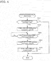
- FIG. 6 is a flowchart illustrating a system activation process executed by the controller 10 according to the embodiment. It should be noted that the system stop process and the system activation process are executed at, for example, a predetermined time interval (for example, every 100 msec).
- the controller 10 determines whether the ignition key is turned OFF by the user of the vehicle or not (Step S101). When it is determined that the ignition key is not turned OFF, the controller 10 terminates this system stop process.
- the controller 10 opens the anode pressure control valve 36 (Step S102), and detects the pressure inside the first pipe, that is, the first pipe pressure P 1 using the first pipe pressure sensor 38 (Step S103).
- Step S104 determines whether the first pipe pressure P 1 detected at Step S103 is less than the predetermined pressure P 0 or not.
- the controller 10 repeats the process at Steps S103 and S104.
- Step S105 the controller 10 closes the anode pressure control valve 36 (Step S105), and executes the system stop sequence of the fuel cell system 100 (Step S106), and then, terminates this system stop process.
- the system stop sequence is simply performed by a known method corresponding to a system configuration of the fuel cell system 100; therefore, the detailed explanation will not be elaborated here.
- the controller 10 first, determines whether the ignition key is turned ON by the user of the vehicle or not (Step S201). When it is determined that the ignition key is not turned ON, the controller 10 terminates this system activation process.
- the controller 10 opens the anode pressure control valve 36 (Step S202). Then, the controller 10 measures a time from the anode pressure control valve 36 is opened to determine whether a predetermined time has elapsed or not (Step S203). The controller 10 stands by at Step S203 until the predetermined time elapses.
- the controller 10 closes the anode pressure control valve 36 (Step S204), executes the activation sequence to activate the fuel cell stack 1 (Step S205), and terminates this system activation process.
- the activation sequence of the fuel cell stack 1 is simply performed by a known method corresponding to a system configuration of the fuel cell system 100; therefore, the detailed explanation will not be elaborated here.
- FIG. 7 is a timing chart of the solenoid current corresponding to the timing chart in FIG. 3 .
- FIGS. 7 (a) to (c) are similar to FIGS. 3 (a) to (c) ; therefore, the detailed explanation will not be elaborated.
- FIG. 7(e) illustrates the solenoid current supplied to the solenoid coil of the anode pressure control valve 36.
- the controller 10 outputs a solenoid current command value as well as the duty command value to the anode pressure control valve 36 as soon as the system stop sequence of the fuel cell system 100 is started.
- the anode pressure control valve 36 performs the valve open operation on the basis of these duty command value and solenoid current command value.
- the controller 10 sets the command duty ratio and the solenoid current command value of the anode pressure control valve 36 and outputs the command duty ratio and the solenoid current command value to the anode pressure control valve 36 before the system activation sequence is started.
- the anode pressure control valve 36 performs the valve open operation on the basis of the command duty ratio and the solenoid current command value.
- the controller 10 warms up the anode pressure control valve 36 by continuing the solenoid current command value for a predetermined time.
- the predetermined time is, for example, approximately one to several seconds.
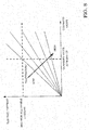
- FIG. 8 is a graph illustrating a relation between the solenoid current that should be supplied to the anode pressure control valve 36 and the ambient temperature of the anode pressure control valve 36. As illustrated in FIG. 8 , the maximum allowable current value by a quality assurance is set for the solenoid current. A plurality of straight lines radially extending indicate the solenoid current values at respective temperatures.
- a solenoid current value corresponding to a predetermined command value at warming up becomes high as the ambient temperature is low.
- the controller 10 determines the solenoid current value on the basis of the ambient temperature of the anode pressure control valve 36 detected by the temperature sensor 60 by referring to this graph.
- FIG. 9 illustrates the flow-in state of the anode gas when the anode pressure control valve 36 is warmed up in the case where the first pipe pressure P 1 is less than the predetermined pressure P 0 .
- the anode gas has flown into a portion indicated by diagonal lines in the first pipe 32 and the second pipe 33.
- the anode gas flows up to a middle of the second pipe 33.
- the anode pressure control valve 36 is closed after the first pipe pressure P 1 is depressurized to less than the predetermined pressure P 01 when the fuel cell system 100 is stopped; therefore, the boundary surface (the hydrogen front) is not generated inside the fuel cell stack 1 even when the anode pressure control valve 36 is warmed up. Accordingly, for example, a catalyst degradation inside the fuel cell stack 1 can be effectively prevented.
- first pipe pressure P 1 is equal to or more than the predetermined pressure P 01 and less than the second predetermined pressure P 02 .
- a brief description will be given of a timing chart from the start of the system stop sequence of the fuel cell system 100 to the next activation of the fuel cell system 100.
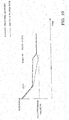
- FIG. 10 is a timing chart when the fuel cell system 100 is stopped with the first pipe pressure P 1 being equal to or more than the predetermined pressure P 01 .
- the fuel cell system 100 is stopped in a state where the first pipe pressure P 1 and the second pipe pressure P 2 are equal to or more than the predetermined pressure P 01 .
- the second pipe pressure P 2 is gradually decreased by the anode gas and the cathode gas remained inside the fuel cell stack 1 reacting and the anode gas leaking outside the system.
- the first pipe pressure P 1 hardly changes; therefore, the entire pressure of the anode system from the anode pressure control valve 36 to the purge valve 37 including the first pipe 32 and the second pipe 33 becomes equal to or more than the predetermined pressure P 01 when the anode pressure control valve 36 is warmed up.
- FIG. 11 is a drawing illustrating a flow-in state of the anode gas when the anode pressure control valve 36 is warmed up in the case where the first pipe pressure P 1 is equal to or more than the predetermined pressure P 01 .
- the anode gas has flown into a portion indicated by the diagonal lines in the first pipe 32, the second pipe 33, and the fuel cell stack 1.
- the boundary surface (the hydrogen front) between the remained gas and the anode gas exists inside the fuel cell stack 1. Therefore, a local cell in which the upstream of the anode gas flow passage inside the fuel cell stack 1 is an anode electrode and the downstream is a cathode electrode is formed in a side of the anode electrode.
- the boundary surface the hydrogen front
- FIG. 12 is a drawing illustrating a flow-in state of the anode gas when the anode pressure control valve 36 is warmed up in the case where the first pipe pressure P 1 is equal to or more than the second predetermined pressure P 02 .
- the anode gas has flown into portions indicated with the diagonal lines in the first pipe 32, the second pipe 33, the fuel cell stack 1, and the anode gas discharge passage 34.
- the first pipe pressure P 1 may be adjusted to equal to or more than the second predetermined pressure P 02 instead of adjusting the first pipe pressure P 1 to less than the predetermined pressure P 01 .
- the second predetermined pressure P 02 is set to a pressure smaller than (the maximum value of) the durability pressure P max that reduces the degradation of the durability of the fuel cell stack 1 at the activation of the fuel cell system 100.
- FIG. 13 is a graph illustrating relations between the volume ratio V 2 /V 1 of the second pipe system to the first pipe 32, and the predetermined pressure P 01 and the second predetermined pressure P 02 .
- the boundary surface between the anode gas and the remained gas does not exist inside the fuel cell stack 1 when the predetermined pressure is in the region A and the region B; therefore, the fuel cell system 100 is only necessary to be designed such that the volume ratio V 2/ V 1 falls within a portion with vertical lines illustrated in FIG. 13 .
- a region between the two regions A and B defines the region X, the region A corresponds to the predetermined pressure P 01 , and the region B corresponds to the second predetermined pressure P 02 .
- an upper limit of the region B indicates the maximum value P max of the durability pressure.
- P min is set as a lower limit value of the predetermined pressure considering a hydrogen retention capacity of the fuel cell stack 1 at the activation of the fuel cell system 100.
- This "hydrogen retention capacity” means a condition to effectively cause the electrode reaction inside the fuel cell stack 1 at the next activation of the fuel cell system 100.
- the predetermined pressure is only necessary to be equal to or more than the pressure (the lower limit pressure) P min that corresponds to an amount of the anode gas to be remained inside the fuel cell stack 1 after the fuel cell system 100 is stopped. Therefore, in FIG. 13 , a portion less than the lower limit pressure P min in the region A is excluded from the portion with the vertical lines.
- the fuel cell system 100 configured so as to thus set the predetermined pressure ensures obtaining the hydrogen retention capacity in whatever activation condition and satisfying the request of the anode gas boost speed inside the fuel cell stack 1, and furthermore, ensures reducing the overshooting of the anode gas pressure.
- the predetermined pressure being the pressure that satisfies the durability pressure of the fuel cell stack 1 ensures effectively preventing the damage to, for example, each electrode and electrolyte membrane inside the fuel cell stack 1.
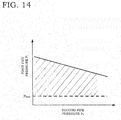
- FIG. 14 is another graph illustrating a relation between the first pipe pressure P 1 and the second pipe pressure P 2 when the fuel cell system is stopped.
- a portion with diagonal lines illustrated in FIG. 14 is a region in which the first pipe pressure P 1 and the second pipe pressure P 2 satisfy the condition of the embodiment.
- the fuel cell system 100 is the fuel cell system 100 that supplies the anode gas and the cathode gas to the fuel cell stack 1 (the fuel cell) to cause the fuel cell stack 1 to generate the electricity.
- the fuel cell system 100 includes the high pressure tank 31, which stores the anode gas supplied to the fuel cell stack 1 in a high pressure, the anode gas supply passage constituted of the first pipe 32 and the second pipe 33 to supply the anode gas from the high pressure tank 31 to the fuel cell stack 1, the anode pressure control valve 36, which is disposed on the anode gas supply passage and adjusts the anode gas pressure of the fuel cell stack 1, the anode gas valve 35, which is disposed between the high pressure tank 31 and the anode pressure control valve 36 and adjusts a source pressure of the anode pressure control valve 36, and the controller 10, which serves as a valve control unit that controls opening and closing of the anode pressure control valve 36 and the anode gas valve 35 on the basis of the operating state of the fuel cell system 100.
- the controller 10 controls the anode pressure control valve 36 and then close the anode pressure control valve 36 after the controller 10 closes the anode gas valve 35 such that the first pipe pressure P 1 , which is the pressure inside the first pipe 32 between the anode gas valve 35 and the anode pressure control valve 36 in the anode gas supply passage, becomes less than the predetermined pressure before the fuel cell system 100 is stopped.
- the controller 10 opens the anode pressure control valve 36 at the activation of the fuel cell system 100.
- the predetermined pressure is configured to be smaller than the pressure that degrades the durability of the fuel cell stack 1 at the activation of the fuel cell system 100. Since the fuel cell system 100 according to the embodiment is thus configured, the following action and effect are provided.
- the first pipe pressure P 1 which is the pressure in the first pipe 32 in the anode gas supply passage, is configured to be the predetermined pressure (the pressure smaller than the pressure that degrades the durability of the fuel cell stack 1) smaller than the maximum value P max of the durability pressure when the system is stopped. Therefore, the damage to, for example, each electrode and electrolyte membrane inside the fuel cell stack 1 can be effectively prevented even when the anode pressure control valve 36 is opened for warming up the anode pressure control valve 36 at the activation of the system.
- the predetermined pressure is only necessary to be the pressure with which the boundary surface between the anode gas inside the first pipe 32 and the remained gas inside the second pipe 33 between the anode pressure control valve 36 and the fuel cell stack 1 is outside the fuel cell stack 1 (that is, the boundary surface does not stay inside the fuel cell stack 1) when the anode pressure control valve 36 is opened at the activation of the fuel cell system 100. That is, in the above-described embodiment, the predetermined pressure is only necessary to be the pressure that provides the state illustrated in FIG. 9 or FIG. 12 .
- the boundary surface (the hydrogen front) between the anode gas and the remained gas (including the cathode gas) exists inside the fuel cell stack 1 As soon as there provides a state where the boundary surface (the hydrogen front) between the anode gas and the remained gas (including the cathode gas) exists inside the fuel cell stack 1, the local cell with the upstream of the anode gas flow passage inside the fuel cell stack 1 as the anode electrode and the downstream as the cathode electrode is formed in the anode electrode side.
- the boundary surface (the hydrogen front) At the proximity of the boundary surface (the hydrogen front), the carbon of the catalyst layer inside the fuel cell stack 1 is deteriorated due to the reaction of the anode gas with the cathode gas.
- setting the predetermined pressure ensures effectively preventing, for example, the deterioration of the catalyst layer inside the fuel cell stack 1.
- the predetermined pressure is only necessary to be equal to or more than the pressure necessary at the activation of the fuel cell system 100 (that is, the pressure necessary for activating the fuel cell system 100). With this, there is no influence on the above-described hydrogen retention capacity.
- the fuel cell system 100 is the fuel cell system 100 that supplies the anode gas and the cathode gas to the fuel cell stack 1 to cause the fuel cell stack 1 to generate the electricity.
- the fuel cell system 100 includes the high pressure tank 31, which stores the anode gas supplied to the fuel cell stack 1 in a high pressure, the anode gas supply passage constituted of the first pipe 32 and the second pipe 33 to supply the anode gas from the high pressure tank 31 to the fuel cell stack 1, the anode pressure control valve 36, which is disposed on the anode gas supply passage and adjusts the anode gas pressure of the fuel cell stack 1, the anode gas valve 35, which is disposed between the high pressure tank 31 and the anode pressure control valve 36 and adjusts a source pressure of the anode pressure control valve 36, and the controller 10, which serves as a valve control unit that controls opening and closing of the anode pressure control valve 36 and the anode gas valve 35 on the basis of the operating state of the fuel cell system 100.
- the controller 10 controls the first pipe pressure P 1 , which is the pressure inside the first pipe 32 between the anode gas valve 35 and the anode pressure control valve 36 in the anode gas supply passage, to be a predetermined operation pressure while the fuel cell system 100 is operating.
- the controller 10 depressurizes the first pipe pressure P 1 to the predetermined pressure lower than the predetermined operation pressure and then close the anode pressure control valve 36 after the controller 10 closes the anode gas valve 35 before the fuel cell system 100 is stopped and open the anode pressure control valve 36 at the activation of the fuel cell system 100.
- the first pipe pressure P 1 is decreased to the predetermined pressure lower than the predetermined operation pressure when the fuel cell system 100 is stopped. Therefore, the damage to, for example, each electrode and electrolyte membrane inside the fuel cell stack 1 can be effectively prevented even when the anode pressure control valve 36 is opened for warming up the anode pressure control valve 36 at the activation of the system, similarly to the above.
- the current command value supplied to the anode pressure control valve 36 at the activation of the fuel cell system 100 is only necessary to be the command value of the current within a guaranteed range of the anode pressure control valve 36 even in a condition (usually a condition at the minimum temperature in the usage environment) where the electrical resistance becomes the smallest in the usage condition where the anode pressure control valve 36 is used.
- a condition usually a condition at the minimum temperature in the usage environment
- the electrical resistance of the solenoid coil and the sliding resistance of the plunger are small. Therefore, applying the voltage of a normal voltage value increases the current value.
- the embodiment uses the command value that does not cause the current applied to the solenoid coil to be equal to or more than the predetermined value when the anode pressure control valve 36 is warmed up.
- the controller 10 is configured to supply the current to the anode pressure control valve 36 at the activation of the fuel cell system 100 and finish the supply of the current when the predetermined time elapses.
- applying the current to the anode pressure control valve 36 for the predetermined time is determined to be a completion of the warm up of the anode pressure control valve 36, and then the controller 10 simply terminates the current supply.
- the "predetermined time" is simply set by, for example, an experiment in advance.
- applying the current to warm up the anode pressure control valve 36 warms the solenoid coil due to the current application, thus, increasing the electrical resistance. Therefore, the current is gradually decreased, and it is also possible to determine the completion of the warm up after confirming the state.
- determining the warm up completion of the anode pressure control valve 36 is simply performed in a state where the current is supplied to the anode pressure control valve 36 using the DC/DC converter 6 after a device of a power electric system of the fuel cell system 100 is activated.
- the completion of the warm up of the anode pressure control valve 36 is determined on the basis of the current value supplied to the anode pressure control valve 36 after a power electric system activation sequence of the fuel cell system 100 is operated. It is preferred to make a determination after the power supply voltage is stabilized to be constant in order to increase a determination accuracy of the warm up time (the above-described "predetermined time") of the anode pressure control valve 36.
- the warm up completion using the temperature sensor 60 for detecting the ambient temperature of the anode pressure control valve 36. That is, as soon as the warm up of the anode pressure control valve 36 is started, the ambient temperature of the anode pressure control valve 36 may be measured using the temperature sensor 60 and the warm up completion may be determined when the condition that the ambient temperature becomes equal to or more than the predetermined temperature is satisfied.
- Applying the current to open the anode pressure control valve 36 causes a heat generation in the solenoid coil inside to increase the ambient temperature.
- the completion of the warm up of the anode pressure control valve 36 may be determined.
- a necessity to warm up the anode pressure control valve 36 may be determined using the temperature sensor 60 for detecting the ambient temperature of the anode pressure control valve 36.
- the temperature sensor 60 detects the temperature before the warm up of the anode pressure control valve 36 and when the detected ambient temperature is less than the predetermined temperature, it is only necessary to be configured such that the warm up of the anode pressure control valve 36 is executed at the activation of the fuel cell system 100. This configuration ensures, by not executing the warm up when the warm up of the anode pressure control valve 36 is not necessary, preventing a wasteful use of the electric power of the fuel cell system 100 and shortening the activation time of the fuel cell system 100.
- the "predetermined temperature” in this case is determined by, for example, an experiment in advance. That is, a relation between the ambient temperature and an external temperature at the activation and the electrical resistance, a control accuracy (an overshooting amount) of the solenoid coil then is obtained by the experiment, and then it is only necessary to set the allowed temperature as the predetermined temperature. Taking the control accuracy into consideration is because the electrical resistance of the solenoid coil and the sliding resistance of the plunger are changed by the ambient temperature, thus, affecting the opening degree of the anode pressure control valve 36.
- the temperature sensor 60 for detecting the ambient temperature of the anode pressure control valve 36 may be substituted with an external temperature sensor that detects the external temperature, a cooling water temperature sensor that detects the temperature of the cooling water for cooling the fuel cell stack 1, and similar sensor.
- the first pipe pressure P 1 which is the pressure inside the first pipe 32, is not increased to the pressure of the normal operation after the completion of the warm up of the anode pressure control valve 36 but it is configured to be executed at the predetermined time point in the system activation sequence. In this embodiment, it is configured such that the pressure inside the first pipe 32 is increased to the pressure at the normal operation in the system activation process.
- FIG. 15 is a timing chart that illustrates a stop and activation method for the fuel cell system according to the second embodiment.
- FIGS. 15 (a) to (c) are similar to FIGS. 3 (a) to (c) ; therefore, the detailed description will not be elaborated.
- FIG. 15 (f) illustrates the opening degree of the anode gas valve 35.
- the warm up of the anode pressure control valve 36 is performed.
- the anode gas valve 35 is opened to boost the first pipe pressure P 1 , which is the pressure inside the first pipe 32, to the predetermined operation pressure. This ensures shortening the activation time of the fuel cell system 100 and obtaining a pressure control accuracy by the anode pressure control valve 36.
- the pressure of the anode gas stored inside the high pressure tank 31 is, for example, approximately 70 MPa (megapascal)
- the first pipe pressure P 1 between the anode gas valve 35 and the anode pressure control valve 36 is, for example, approximately two to four MPa
- the second pipe pressure P 2 adjusted by the anode pressure control valve 36 is, for example, approximately 200 kPa.
- FIG. 16 is a flowchart illustrating the system activation process executed by the controller 10 according to the embodiment. Steps similar to those in the flowchart in FIG. 6 have identical step numbers attached.
- the controller 10 first, determines whether the ignition key is turned ON by the user of the vehicle or not (Step S201). When it is determined that the ignition key is not turned ON, the controller 10 terminates this system activation process.
- the controller 10 opens the anode pressure control valve 36 (Step S202). Then, the controller 10 measures the time from the anode pressure control valve 36 is opened to determine whether the predetermined time has elapsed or not (Step S203). The controller 10 stands by at Step S203 until the predetermined time elapses.
- the controller 10 closes the anode pressure control valve 36 (Step S204), and after the anode pressure control valve 36 is fully closed, the anode gas valve 35 is opened (Step S301). Then, the controller 10 monitors the first pipe pressure P 1 , which is the pressure inside the first pipe 32.
- the controller 10 determines whether the first pipe pressure P 1 is equal to or more than the predetermined operation pressure or not (Step S302). The controller 10 stands by at Step S302 until the first pipe pressure P 1 becomes equal to or more than the predetermined operation pressure.
- the controller 10 closes the anode gas valve 35 (Step S303), executes the activation sequence to activate the fuel cell stack 1 (Step S205), and then terminates this system activation process.
- the activation sequence of the fuel cell stack 1 is simply performed by a known method corresponding to a system configuration of the fuel cell system 100; therefore, the detailed explanation will not be elaborated here.
- the fuel cell system 100 is configured such that the controller 10 opens the anode pressure control valve 36 at the activation of the fuel cell system 100, closes the valve after the predetermined time elapses, and then opens the anode gas valve 35 so as to set the first pipe pressure P 1 to the predetermined operation pressure and closes the anode gas valve 35 and then executes the activation of the fuel cell stack 1.
- this ensures obtaining the pressure control accuracy of the anode pressure control valve 36 by boosting the first pipe pressure P 1 to the medium pressure.
- the first pipe pressure P 1 is promptly boosted to the medium pressure after the warm up of the anode pressure control valve 36.
- the anode pressure control valve 36 is warmed up by opening and closing the anode pressure control valve 36 before the activation of the fuel cell stack 1.
- it is configured to determine whether the warm up of the anode pressure control valve 36 is performed or not by confirming the first pipe pressure P 1 .
- FIG. 17 is a flowchart illustrating a system activation process executed by the controller 10 in the third embodiment. Steps similar to those in the flowcharts in FIG. 6 and FIG. 16 have identical step numbers attached.
- the controller 10 first, determines whether the ignition key is turned ON by the user of the vehicle or not (Step S201). When it is determined that the ignition key is not turned ON, the controller 10 terminates this system activation process.
- the controller 10 determines whether the first pipe pressure P 1 is less than the durability pressure or not on the basis of a detected value of the first pipe pressure sensor 38 (Step S401).
- the controller 10 turns a warm up NG flag ON (Step S402), executes the fuel cell stack activation process (Step S205), and then terminates this system activation process.
- the controller 10 when the warm up NG flag is set to ON, in the fuel cell stack activation process, the controller 10 is only necessary to set a target pressure smaller than a target pressure at the activation based on the pressure in the anode gas flow passage inside the fuel cell stack 1 detected by the pressure sensor 39 and open the anode pressure control valve 36 corresponding to the setting value. This cannot perform the warm up of the anode pressure control valve 36, however, ensures preventing the durability of the fuel cell stack 1 from being degraded.
- the controller 10 opens the anode pressure control valve 36 (Step S202). Then, the controller 10 measures the time from when the anode pressure control valve 36 is opened to determine whether the predetermined time has elapsed or not (Step S203). The controller 10 stands by at Step S203 until the predetermined time elapses.
- the controller 10 closes the anode pressure control valve 36 (Step S204), and after the anode pressure control valve 36 is fully closed, opens the anode gas valve 35 (Step S301). Then, the controller 10 monitors the first pipe pressure P 1 , which is the pressure inside the first pipe 32.
- the controller 10 determines whether the first pipe pressure P 1 has become equal to or more than the predetermined operation pressure or not (Step S302). The controller 10 stands by at Step S302 until the first pipe pressure P 1 becomes equal to or more than the predetermined operation pressure.
- the controller 10 closes the anode gas valve 35 (Step S303), executes the activation sequence to activate the fuel cell stack 1 (Step S205), and terminates this system activation process.
- the activation sequence for the fuel cell stack 1 is simply performed by a known method corresponding to a system configuration of the fuel cell system 100; therefore, the detailed explanation will not be elaborated here.
- the fuel cell system 100 is configured so as not to open the anode pressure control valve 36, that is, not to warm up the anode pressure control valve 36 at the activation of the fuel cell system 100 when the first pipe pressure P 1 before activating the fuel cell system 100 is equal to or more than the durability pressure.
- the first pipe pressure P 1 is equal to or more than the predetermined pressure, such as when the fuel cell system 100 is stopped due to Fail and the like, it is possible to damage, for example, each electrode and electrolyte membrane inside the fuel cell stack 1. Opening the anode pressure control valve 36 possibly cause the boundary surface (the hydrogen front) between the anode gas and the remained gas inside the fuel cell stack 1. In the embodiment, thus configuring the fuel cell system 100 ensures effectively preventing these failures from occurring.
- FIG. 18 is a drawing illustrating an overall configuration of the fuel cell system 100' in the fourth embodiment.
- identical reference numerals are used to appropriately omit duplicate explanations.
- control methods of the present invention have been executed in the fuel cell system of the anode gas non-circulation type.
- these control methods are executed in a fuel cell system of an anode gas circulation type.
- FIG. 18 is a drawing illustrating the overall configuration of the fuel cell system 100 in the fourth embodiment. As illustrated in FIG. 18 , the fuel cell system 100 according to the embodiment is the fuel cell system of the anode gas circulation type.
- the anode gas supplying/discharging device 3 is a device that supplies the anode gas to the fuel cell stack 1 and circulate the anode off-gas discharged from the fuel cell stack 1 into the fuel cell stack 1.
- the anode gas supplying/discharging device 3 includes the high pressure tank 31, the first pipe 32 and the second pipe 33 on the anode gas supply passage, an anode gas circulation passage 40, the anode gas valve 35, the anode pressure control valve 36, the purge valve 37, an ejector 42, and an anode circulation pump 41. It should be noted that, while the illustration is omitted, on the anode gas circulation passage 40, a gas-liquid separation device to separate the anode off-gas inside the anode gas circulation passage 40 and the water (a liquid water) generated by a water vapor generated by the electrode reaction condensing.
- the anode gas circulation passage 40 is a passage that circulates the anode off-gas discharged from the fuel cell stack 1 into the anode gas supply passage.
- the anode gas circulation passage 40 has one end coupled to the anode gas outlet hole of the fuel cell stack 1 and the other end coupled to a suction port of the ejector 42.
- the ejector 42 is disposed between the anode pressure control valve 36 and the fuel cell stack 1 on the anode gas supply passage.
- the ejector 42 is a mechanical pump disposed at a portion where the anode gas circulation passage 40 joins to the anode gas supply passage. Disposing the ejector 42 on the anode gas supply passage ensures circulating the anode off-gas into the fuel cell stack 1 with a simple constitution.
- the ejector 42 suctions the anode off-gas from the fuel cell stack 1 by accelerating a flow rate of the anode gas supplied from the anode pressure control valve 36 to generate a negative pressure.
- the ejector 42 discharges the suctioned anode off-gas into the fuel cell stack 1 together with the anode gas supplied from the anode pressure control valve 36.
- the ejector 42 is constituted of, for example, a conical shaped nozzle having an opening narrowed toward the fuel cell stack 1 from the anode pressure control valve 36 and a diffuser including a suction port suctioning the anode off-gas from the fuel cell stack 1. It should be noted that, while in this embodiment, the ejector 42 is used as joining means of the anode gas supply passage and the anode gas circulation passage 40, the anode gas supply passage may simply be joined by the anode gas circulation passage 40.
- the anode circulation pump 41 is disposed on the anode gas circulation passage 40.
- the anode circulation pump 41 circulates the anode off-gas into the fuel cell stack 1 via the ejector 42.
- a rotation speed of the anode circulation pump 41 is controlled by the controller 10. This adjusts the flow rate of the anode off-gas circulated in the fuel cell stack 1.
- the predetermined pressure is simply determined so as to be in the region A in the diagonal lines in the graph as illustrated in FIG. 13 on the basis of the volume ratio of the volume of the second pipe system, which is the combination of the second pipe 33 and the anode gas circulation passage 40, to the volume inside the first pipe 32. It should be noted that while it is possible to set the predetermined pressure to be in the region B, it is presumed that the anode gas flows into a side of the anode gas circulation passage 40 via the ejector 42 when the anode pressure control valve 36 is warmed up. Therefore, it is only necessary to confirm its behavior by, for example, an experiment, and then set to be in the region B.
- the boundary surface (the hydrogen front) between the anode gas and the remained gas may be eliminated by actively mixing the remained gas and the anode gas by activating the anode circulation pump 41 simultaneously with opening of the anode pressure control valve 36 for the warm up. This ensures effectively preventing the boundary surface from being generated inside the fuel cell stack 1 and preventing the damage to, for example, each electrode and electrolyte membrane inside the fuel cell stack 1.
- executing the system stop process and the system activation process in the above-described first embodiment to third embodiment ensures providing an effect similar to the above-described embodiments.
Landscapes
- Chemical & Material Sciences (AREA)
- Chemical Kinetics & Catalysis (AREA)
- Electrochemistry (AREA)
- General Chemical & Material Sciences (AREA)
- Life Sciences & Earth Sciences (AREA)
- Engineering & Computer Science (AREA)
- Manufacturing & Machinery (AREA)
- Sustainable Development (AREA)
- Sustainable Energy (AREA)
- Fuel Cell (AREA)
Abstract
Description
- The present invention relates to a fuel cell system configured to warm up an anode pressure control valve at an activation and a control method for the fuel cell system.
- There are proposed an anode gas non-circulation type fuel cell system and an anode gas circulation type fuel cell system for a fuel cell system. The anode gas non-circulation type fuel cell system does not circulate an anode gas, which is a fuel gas, and discharges an anode off-gas after a reaction together with a cathode off-gas. The anode gas circulation type fuel cell system circulates the anode gas, and additionally supplies the anode gas from a high pressure tank as necessary.
- In order to supply the anode gas to a fuel cell (a fuel cell stack), a high pressure anode gas stored in the high pressure tank is depressurized to a medium pressure via a medium pressure control valve, and corresponding to a load request and an operating state of the fuel cell, the medium pressure anode gas is supplied to the fuel cell at a predetermined duty ratio by an anode pressure control valve disposed in a downstream of the medium pressure control valve.
- The anode pressure control valve usually uses a normally closed solenoid valve, which is an ON/OFF type valve internally including a solenoid coil. A duty ratio of the anode pressure control valve is operated by a controller that controls the entire fuel cell. A drive signal to the solenoid coil is supplied via a DC/DC converter for a high-voltage battery or a fuel cell. Therefore, while the fuel cell system is operating, a voltage of this drive signal is stable.
- With such a solenoid valve, an operating state is susceptible to a temperature change in a usage environment. That is, the temperature change in the usage environment changes, for example, an electrical resistance of the solenoid coil of the solenoid valve and a sliding resistance of a plunger as a movable iron core.
- In view of this, even though the drive signal with an identical duty ratio is output to the solenoid valve, a valve opening degree of the anode pressure control valve is possibly different depending on the usage environment. In particular, at a first activation of the fuel cell system, such an influence becomes remarkable since the drive signal is not supplied to the solenoid valve for a while.
- When a usage environment temperature is below zero, the fuel cell system is activated below zero. Then, there has been a problem that, at a first driving of the anode pressure control valve, a reaction of the plunger cannot follow the duty ratio to cause an anode gas pressure inside the fuel cell to overshoot.
- In order to solve such a problem, for example,
JP2998549B -
JP2008-273338A - However, in the control device for the current control type solenoid valve disclosed in
JP2998549B - In the braking control device disclosed in
JP2008-273338A - In this braking control device, a measure to deal with a case where the ambient temperature and the coil temperature cannot be estimated is necessary. Then, in this braking control device, an allowable current value at a minimum temperature is supplied in order to prevent an overcurrent from being applied to the solenoid coil even when the coil temperature cannot be estimated.
- When the actual coil temperature is high in such a case, that is, when the coil temperature cannot be estimated, it is possible that an anode gas boost speed inside the fuel cell slows down because the current supplied to the solenoid coil is corrected to a safety side. The slowed down anode gas boost speed possibly causes damages to, for example, an electrolyte membrane inside the fuel cell depending on the operating state of the fuel cell.
- The present invention has been made focusing on the above-described problems and it is one of the objectives of the present invention to provide a fuel cell system configured to satisfy a request of an anode gas boost speed inside the fuel cell and reduce an overshooting of the anode gas in whatever activation condition and a control method for the fuel cell system.
- According to an aspect of this invention, there is provided a fuel cell system that supplies an anode gas and a cathode gas to a fuel cell to cause the fuel cell to generate an electricity. The fuel cell system includes a high pressure tank that stores the anode gas in a high pressure, the anode gas being supplied to the fuel cell, an anode gas supply passage configured to supply the anode gas to the fuel cell from the high pressure tank, an anode pressure control valve disposed on the anode gas supply passage, the anode pressure control valve adjusting an anode gas pressure of the fuel cell, an anode gas valve disposed between the high pressure tank and the anode pressure control valve, the anode gas valve adjusting a source pressure of the anode pressure control valve, and a valve control unit configured to control to open and close the anode pressure control valve and the anode gas valve on the basis of an operating state of the fuel cell system. The valve control unit controls the anode pressure control valve and then closes the anode pressure control valve after the valve control unit closes the anode gas valve such that a first pipe pressure becomes less than a predetermined pressure before the fuel cell system is stopped, the first pipe pressure being a pressure inside a first pipe between the anode gas valve and the anode pressure control valve in the anode gas supply passage. On the other hand, the valve control unit opens the anode pressure control valve at an activation of the fuel cell system. In this case, the predetermined pressure is smaller than a pressure that degrades a durability of the fuel cell at the activation of the fuel cell system.
-
-
FIG. 1 is a drawing illustrating an overall configuration of a fuel cell system in a first embodiment of the present invention. -
FIG. 2 is an enlarged view of an anode gas supplying/discharging device inFIG. 1 . -
FIG. 3 is a timing chart illustrating a stopping and activating method for the fuel cell system of the embodiment. -
FIG. 4 is a graph illustrating a relation between a first pipe pressure and a second pipe pressure when the fuel cell system is stopped. -
FIG. 5 is a flowchart illustrating a system stop process executed by a controller according to the embodiment. -
FIG. 6 is a flowchart illustrating a system activation process executed by the controller according to the embodiment. -
FIG. 7 is another timing chart illustrating a stopping and activating method for the fuel cell system of the embodiment. -
FIG. 8 is a graph illustrating a relation between a solenoid current and an ambient temperature in an anode pressure control valve. -
FIG. 9 is a drawing illustrating a flow-in state of an anode gas when the anode pressure control valve is warmed up in the case where the first pipe pressure is less than a predetermined pressure. -
FIG. 10 is a timing chart when the fuel cell system is stopped with the first pipe pressure is equal to or more than the predetermined pressure. -
FIG. 11 is a drawing illustrating a flow-in state of the anode gas when the anode pressure control valve is warmed up in the case where the first pipe pressure is equal to or more than the predetermined pressure. -
FIG. 12 is a drawing illustrating a flow-in state of the anode gas when the anode pressure control valve is warmed up in the case where the first pipe pressure is equal to or more than a second predetermined pressure. -
FIG. 13 is a graph illustrating a relation between a volume ratio of a second pipe system to a first pipe and the predetermined pressure. -
FIG. 14 is another graph illustrating a relation between the first pipe pressure and the second pipe pressure when the fuel cell system is stopped. -
FIG. 15 is a timing chart illustrating a stopping and activating method for the fuel cell system in a second embodiment. -
FIG. 16 is a flowchart illustrating a system activating process executed by a controller in the second embodiment. -
FIG. 17 is a flowchart illustrating a system activating process executed by a controller in a third embodiment. -
FIG. 18 is a drawing illustrating an overall configuration of a fuel cell system in a fourth embodiment. - The following describes embodiments of the present invention with reference to attached drawings.
-
FIG. 1 is a drawing illustrating an overall configuration of afuel cell system 100 according to a first embodiment of the present invention. Thefuel cell system 100 in the embodiment is a fuel cell system of an anode gas non-circulation type. Thisfuel cell system 100 constitutes a power supply system that supplies an anode gas (a fuel gas) and a cathode gas (an oxidant gas) necessary for an electric generation to afuel cell stack 1 from an outside to cause an electrode reaction with an anode electrode and a cathode electrode (not illustrated) to cause thefuel cell stack 1 to generate an electricity in accordance with an operating state of aload device 5 electrically coupled. Thisfuel cell system 100 is mounted, for example, in an electric vehicle in which a drive motor drives the vehicle. It should be noted that thisfuel cell system 100 is also applicable to a load of, for example, a device other than a fuel cell vehicle (the electric vehicle using the fuel cell) as long as a driving source is the fuel cell. - As illustrated in
FIG. 1 , thefuel cell system 100 mainly includes thefuel cell stack 1, a cathode gas supplying/discharging device 2, an anode gas supplying/discharging device 3, theload device 5, and acontroller 10. - The
fuel cell stack 1 is a stacked cell in which a plurality of fuel cells (not illustrated) are stacked. Thefuel cell stack 1 is coupled to theload device 5 to supply an electric power generated by the electrode reaction to theload device 5. Thefuel cell stack 1 generates a DC voltage of, for example, several hundred V (volts). - While the illustration is omitted, the
fuel cell stack 1 is constituted by having an electrolyte membrane interposed between the anode electrode (a fuel electrode) and the cathode electrode (an oxidant electrode). When thefuel cell stack 1 is operating, hydrogen is ionized in the anode electrode and hydrogen ions and electrons are generated. In the cathode electrode, the hydrogen ions and electrons generated in the anode electrode react with oxygen, and water is generated. - The cathode gas supplying/discharging
device 2 is a device that supplies the cathode gas to thefuel cell stack 1 and discharges a cathode off-gas discharged from thefuel cell stack 1 into an atmosphere. It should be noted that the cathode off-gas includes oxygen and nitrogen that did not react in the cathode electrode, generated water vapor, and the like. - The cathode gas supplying/discharging
device 2 includes a cathodegas supply passage 21, acompressor 22, aflow rate sensor 23, apressure sensor 24, a cathodegas discharge passage 25, and a cathodepressure control valve 26. - The cathode
gas supply passage 21 is a passage to supply the cathode gas to thefuel cell stack 1. The cathodegas supply passage 21 has one end that opens and the other end that is coupled to a cathode gas inlet hole of thefuel cell stack 1. - The
compressor 22 is disposed on the cathodegas supply passage 21. Thecompressor 22 retrieves an air containing oxygen from the opening end of the cathodegas supply passage 21 to supply the air to thefuel cell stack 1 as the cathode gas. A rotation speed of thecompressor 22 is controlled by thecontroller 10. - The
flow rate sensor 23 is disposed between thecompressor 22 and thefuel cell stack 1 on the cathodegas supply passage 21. Theflow rate sensor 23 detects a flow rate of the cathode gas supplied to thefuel cell stack 1. Flow rate data of the cathode gas detected by theflow rate sensor 23 is output to thecontroller 10. - The
pressure sensor 24 is disposed between thecompressor 22 and thefuel cell stack 1 on the cathodegas supply passage 21, similarly to theflow rate sensor 23. Thepressure sensor 24 detects the pressure of the cathode gas supplied to thefuel cell stack 1. Pressure data of the cathode gas detected by thepressure sensor 24 is output to thecontroller 10. - The cathode
gas discharge passage 25 is a passage to discharge the cathode off-gas from thefuel cell stack 1. The cathodegas discharge passage 25 has one end that is coupled to a cathode gas outlet hole of thefuel cell stack 1 and the other end that opens. - The cathode
pressure control valve 26 is disposed on the cathodegas discharge passage 25. For the cathodepressure control valve 26, for example, a solenoid valve with which an opening degree of the valve is changeable in phases is used. The cathodepressure control valve 26 is controlled to open and close by thecontroller 10. This open/close control adjusts the cathode gas pressure to a desired pressure. - The anode gas supplying/discharging
device 3 is a device that supplies the anode gas to thefuel cell stack 1 and discharges an anode off-gas discharged from thefuel cell stack 1 into the atmosphere. It should be noted that, while the illustration is omitted, the anode off-gas discharged from thefuel cell stack 1 is mixed with the cathode off-gas inside the cathodegas discharge passage 25 and discharged outside thefuel cell system 100. Since the anode off-gas contains excess hydrogen that was not used in the electrode reaction, the anode off-gas is discharged outside thefuel cell system 100 by being mixed with the cathode off-gas so as to cause a hydrogen concentration in the discharged gas to become equal to or less than a predetermined concentration determined in advance. - The anode gas supplying/discharging
device 3 includes ahigh pressure tank 31, afirst pipe 32 and asecond pipe 33 on an anode gas supply passage, an anodegas discharge passage 34, ananode gas valve 35, an anodepressure control valve 36, apurge valve 37, a firstpipe pressure sensor 38, and a secondpipe pressure sensor 39. - The
high pressure tank 31 is a hydrogen tank that keeps and stores the anode gas (a hydrogen gas), which is supplied to thefuel cell stack 1, in a highly pressured state. - The
first pipe 32 of the anode gas supply passage is a passage to supply the anode gas stored in thehigh pressure tank 31 to thefuel cell stack 1 and a pipe between theanode gas valve 35 and the anodepressure control valve 36. Thesecond pipe 33 of the anode gas supply passage is a pipe between the anodepressure control valve 36 and an anode gas inlet hole. - The anode gas supply passage has one end coupled to the
high pressure tank 31 and the other end coupled to the anode gas inlet hole of thefuel cell stack 1 via the anodepressure control valve 36 and theanode gas valve 35. - The anode
gas discharge passage 34 is a passage through which the anode off-gas discharged from thefuel cell stack 1 flows. The anodegas discharge passage 34 has one end coupled to an anode gas outlet hole of thefuel cell stack 1 and the other end coupled to the cathodegas discharge passage 25 as described above. - The
anode gas valve 35 is disposed on the anode gas supply passage in the downstream of thehigh pressure tank 31. Theanode gas valve 35 is a solenoid valve or a mechanical valve to supply the high pressure anode gas stored in thehigh pressure tank 31 into the first pipe. - It should be noted that while the embodiment provides a case where only one
anode gas valve 35 is disposed on the anode gas supply passage for the convenience of illustration, the present invention is not limited to such a configuration. For example, theanode gas valve 35 may be constituted of a plurality of valves, such as a main stop valve that turns ON/OFF the supply of the high pressure anode gas in thehigh pressure tank 31 and a medium pressure valve and a medium pressure cutoff valve that maintain the anode gas supplied to thefuel cell stack 1 in the medium pressure. - The
anode gas valve 35 may be a mechanical valve or may be a solenoid valve as described above. In the case of the solenoid valve, theanode gas valve 35 is controlled to open and close (ON/OFF) by thecontroller 10 as illustrated inFIG. 1 . - The anode
pressure control valve 36 is disposed between theanode gas valve 35 and the anode gas inlet hole of thefuel cell stack 1 on the anode gas supply passage. For the anodepressure control valve 36, for example, a solenoid valve with which an opening degree of the valve is changeable in phases is used. The anodepressure control valve 36 is controlled to open and close by thecontroller 10. This open/close control adjusts the anode gas pressure supplied to thefuel cell stack 1, that is, the pressure inside the second pipe. - The
purge valve 37 is disposed on the anodegas discharge passage 34. Thepurge valve 37 is a solenoid valve to discharge the anode off-gas to the cathodegas discharge passage 25. An opening degree of thepurge valve 37 is controlled by thecontroller 10. - The first
pipe pressure sensor 38 is disposed on anode gas supply passage between theanode gas valve 35 and the anodepressure control valve 36, that is, on the first pipe. The firstpipe pressure sensor 38 detects the pressure inside the first pipe. Pressure data of the anode gas detected by the firstpipe pressure sensor 38, that is, first pipe pressure data is output to thecontroller 10. - The second
pipe pressure sensor 39 is disposed on the anode gas supply passage between the anodepressure control valve 36 and the anode gas inlet hole of thefuel cell stack 1, that is, on the second pipe. The secondpipe pressure sensor 39 detects the pressure of the anode gas supplied to thefuel cell stack 1. Pressure data of the anode gas detected by the secondpipe pressure sensor 39, that is, second pipe pressure data is output to thecontroller 10. - The
load device 5 is driven by receiving a generated power (a DC power) supplied from thefuel cell stack 1. Theload device 5 is constituted of, for example, an electric motor that drives a vehicle, an inverter for electric motor that converts the DC power output from thefuel cell stack 1 into an AC power supplied to the electric motor, a part of an auxiliary machine that assists the electric generation of thefuel cell stack 1, and a control unit that controls the electric motor. The auxiliary machine of thefuel cell stack 1 includes, for example, thecompressor 22. - As illustrated in
FIG. 2 , theload device 5 further includes a DC/DC converter 6 that boosts a pressure of the DC power output from thefuel cell stack 1 with a predetermined required voltage ratio.FIG. 2 is an enlarged view of the anode gas supplying/dischargingdevice 3 inFIG. 1 . This DC/DC converter 6 is arranged between thefuel cell stack 1 and the electric motor inverter. In the embodiment, while the illustration is omitted, a high pressure battery is disposed in parallel with thefuel cell stack 1 with respect to the DC/DC converter 6. A DC/DC converter for a high pressure battery may be disposed in an output side of this high pressure battery. - It should be noted that the control unit (not illustrated), which controls the
load device 5, outputs a required electric power requested to thefuel cell stack 1 to thecontroller 10. For example, the larger a depression amount of an accelerator pedal disposed in the vehicle becomes, the larger the required electric power of theload device 5 becomes. - Between the
load device 5 and thefuel cell stack 1, acurrent sensor 51 and avoltage sensor 52 are arranged as illustrated inFIG. 1 . - The
current sensor 51 is coupled to a power line between apositive electrode terminal 1p of thefuel cell stack 1 and theload device 5. Thecurrent sensor 51 detects the current output to theload device 5 from thefuel cell stack 1 as an output power of thefuel cell stack 1. Output current data of thefuel cell stack 1 detected by thecurrent sensor 51 is output to thecontroller 10. - The
voltage sensor 52 is coupled between thepositive electrode terminal 1p and a positive electrode terminal In of thefuel cell stack 1. Thevoltage sensor 52 detects an inter-terminal voltage that is a voltage between thepositive electrode terminal 1p and thepositive electrode terminal 1n of thefuel cell stack 1. Output voltage data of thefuel cell stack 1 detected by thevoltage sensor 52 is output to thecontroller 10. - It should be noted that, while the illustration is omitted, an impedance measurement device to detect a wet/dry state of the electrolyte membrane of the
fuel cell stack 1 is further included. This impedance measurement device is a device to measure an internal impedance of thefuel cell stack 1 correlated with the wet/dry state of the electrolyte membrane. - Generally, the less an included water quantity of the electrolyte membrane becomes, that is, the dryer the electrolyte membrane becomes, the larger an electrical resistance component of the internal impedance becomes. On the other hand, the more the included water quantity of the electrolyte membrane becomes, that is, the wetter the electrolyte membrane becomes, the smaller the electrical resistance component of the internal impedance becomes. In view of this, as a parameter to indicate the wet/dry state of the electrolyte membrane, the internal impedance of the
fuel cell stack 1 is used. - The impedance measurement device supplies an alternating current having a frequency suitable for detecting the internal resistance of the
fuel cell stack 1 to thepositive electrode terminal 1p. Then, the impedance measurement device detects an AC voltage generated between thepositive electrode terminal 1p and the positive electrode terminal In by this alternating current of the frequency, and dividing an amplitude of the detected AC voltage by an amplitude of the alternating current supplied to thepositive electrode terminal 1p calculates the internal impedance. - In the embodiment, the
fuel cell stack 1 generates an electric power corresponding to the request of theload device 5, and corresponding to the electric generation state of thefuel cell stack 1, the internal impedance of thefuel cell stack 1, that is, a wetness degree of the electrolyte membrane is controlled. - The
controller 10 is constituted of a microcomputer including, for example, a central processing unit (CPU), a read-only memory (ROM), a random access memory (RAM), and an input/output interface (an I/O interface). - Respective detected data from the
flow rate sensor 23, thepressure sensor 24, the firstpipe pressure sensor 38, the secondpipe pressure sensor 39, thecurrent sensor 51, and thevoltage sensor 52 are input to thecontroller 10. These data are used as parameters related to an operating state of thefuel cell system 100. - The
controller 10 controls the flow rate and the pressure of the cathode gas by controlling thecompressor 22 and the cathodepressure control valve 26 in accordance with the operating state of thefuel cell system 100 and controls the flow rate and the pressure of the anode gas by controlling theanode gas valve 35, the anodepressure control valve 36, and thepurge valve 37. - Next, with reference to
FIG. 2 andFIG. 3 , an operation of thefuel cell system 100 according to the embodiment will be described.FIG. 3 is a timing chart illustrating a control method according to the embodiment. First, a configuration illustrated inFIG. 2 will be briefly described. - The DC/
DC converter 6 is disposed in an output side of thefuel cell stack 1 in the embodiment and is a boost converter that boosts a pressure of the output voltage of thefuel cell stack 1 at a predetermined required voltage ratio. While the illustration is omitted, this DC/DC converter 6 includes a plurality of switching elements. In the embodiment, the switching elements perform switching actions by the control of thecontroller 10 and generate a PWM signal to perform the open/close control of the anodepressure control valve 36 and thepurge valve 37. The generated PWM signal is output to the anodepressure control valve 36, and the anodepressure control valve 36 is controlled to open and close on the basis of a duty ratio of the PWM signal. - While it is not illustrated in
FIG. 1 , at proximity of the anodepressure control valve 36, atemperature sensor 60 to detect an ambient temperature of the anodepressure control valve 36 is disposed. Ambient temperature data of the anodepressure control valve 36 detected by thetemperature sensor 60 is output to thecontroller 10. - In the embodiment, the
fuel cell system 100 is configured to depressurize a first pipe pressure that is a pressure inside thefirst pipe 32 to less than a predetermined pressure as soon as a stop sequence of thefuel cell system 100 starts. - The "predetermined pressure" is a pressure smaller than a durability pressure that reduces a degradation of a durability of the
fuel cell stack 1 at an activation of thefuel cell system 100. Stopping thefuel cell system 100 after depressurizing an inside of thefirst pipe 32 to such a predetermined pressure prevents a damage to each electrode and electrolyte membrane inside thefuel cell stack 1 even if the anodepressure control valve 36 opens with an opening degree greater than a command value at a next activation. It should be noted that the following describes (the maximum values of) the predetermined pressure and the durability pressure as P0 and Pmax, respectively, as necessary. - In the embodiment, at the activation of the
fuel cell system 100, a current is firstly applied to the solenoid coil (not illustrated) of the anodepressure control valve 36 such that the anodepressure control valve 36 is opened to perform a warm up. This ensures the electrical resistance of the solenoid coil of the anodepressure control valve 36 and a sliding resistance of a plunger to be in a state not different from a normal operating state before thefuel cell stack 1 starts operating. Accordingly, in whatever activation condition, a request of an anode gas boost speed inside thefuel cell stack 1 can be satisfied and an overshooting of the anode gas pressure can be reduced. - Here, with reference to
FIG. 4 , a relation between the first pipe pressure inside thefirst pipe 32 and a second pipe pressure inside thesecond pipe 33 when thefuel cell system 100 is stopped will be described.FIG. 4 is a graph illustrating the relation between the first pipe pressure and the second pipe pressure when thefuel cell system 100 is stopped. It should be noted that the second pipe pressure becomes equal to a pressure up to thepurge valve 37 including thefuel cell stack 1; therefore, the description is made for the relation that entirely includes them. - A volume inside the first pipe is V1, a volume of an entire anode system (hereinafter referred to as a "second pipe system") up to the
purge valve 37 including the second pipe and thefuel cell stack 1 is V2. The first pipe pressure and the second pipe pressure when thefuel cell system 100 is stopped are P1 and P2, respectively. An entire pressure after the anodepressure control valve 36 is opened is P3. Then, assuming the anode gas that remains inside the first pipe and the anode off-gas that remains inside the second pipe system as an ideal gas establishes the following relational expression.
fuel cell stack 1, thus establishing the following relational expression.

fuel cell system 100 including thefuel cell stack 1, therefore being a constant value, and similarly, V1 and V2 are constant values. Accordingly, the above-described formula (3) is a linear function between P1 and P2 and provides a graph descending toward the right side as illustrated inFIG. 4 . - Accordingly, it is only necessary to perform the open and close operations of the anode
pressure control valve 36 and thepurge valve 37 when thefuel cell system 100 is stopped such that the first pipe pressure P1 is positioned in a lower side region with respect to a straight line inFIG. 4 . This ensures complying with the withstanding pressure of thefuel cell stack 1 at the next activation of thefuel cell system 100. - It should be noted that the above-described formulae (1) to (3) assume the remained gas as the ideal gas and do not consider an anode gas concentration change (for example, a change by the anode gas that reacts with oxygen or leaks from the pipe) and a change in the ambient temperature after the
fuel cell system 100 is stopped. In particular, depending on the configuration of thefuel cell system 100, it is possible that the anode gas concentration remained inside the first pipe and the second pipe system decreases when a certain amount of time elapses after the system stop. Therefore, the first pipe pressure P1 after the system stop is simply determined by considering the change in the anode gas concentration, the temperature, and similar factor as necessary. - In the embodiment, the
controller 10 performs the open/close control of the anodepressure control valve 36 and thepurge valve 37 when thefuel cell system 100 is stopped so as to satisfy the condition inFIG. 4 . The following describes the control with the timing chart inFIG. 3 . -
FIG. 3 is to illustrate operations of respective parts and a command value from the start of the stop sequence of thefuel cell system 100 to the next activation of thefuel cell system 100.FIG. 3 (a) illustrates changes of the first pipe pressure P1 and the second pipe pressure P2.FIG. 3 (b) illustrates an actual opening degree of the anodepressure control valve 36.FIG. 3 (c) illustrates a duty command value to the anodepressure control valve 36 from thecontroller 10.FIG. 3 (d) illustrates an actual opening degree of theanode gas valve 35. - As soon as a user of the vehicle in which the
fuel cell system 100 is mounted turns OFF an ignition key, thefuel cell system 100 performs the system stop sequence. It should be noted that, while in the embodiment, the activation and stop of thefuel cell system 100 is performed with the ignition key, the present invention is not limited to such a configuration. For example, thefuel cell system 100 of the present invention is mountable in a vehicle including, for example, a start button, instead of the ignition key. - As soon as the system stop sequence is started, the
controller 10 sets a command duty ratio of the anodepressure control valve 36 and outputs the command duty ratio to the anodepressure control valve 36 in order to stop thefuel cell stack 1, The anodepressure control valve 36 performs a valve open operation on the basis of this command duty ratio. At this time, thecontroller 10 also gives a similar open command to thepurge valve 37. Thus, as illustrated inFIG. 3 (a) , the first pipe pressure P1 and the second pipe pressure P2 are gradually decreased. - Then, the
controller 10 outputs the duty command value of closing valve to the anodepressure control valve 36. As soon as the anodepressure control valve 36 is closed, thefuel cell stack 1 inside thefuel cell system 100 stops. At this time, the first pipe pressure P1 has a pressure lower than the illustrated predetermined pressure P0. - It should be noted that, while in the embodiment, the
fuel cell system 100 is stopped at a time point where the anodepressure control valve 36 is closed, a time point of a complete stop of thefuel cell system 100 is not limited to this case. For example, thefuel cell system 100 may perform a predetermined operation of the stop sequence after the anodepressure control valve 36 is closed, or alternatively, may open the anodepressure control valve 36 and thepurge valve 37 after the stop sequence of thefuel cell system 100 is completely finished to cause the first pipe pressure P1 to be less than the predetermined pressure P0. - Then, during the stop of the
fuel cell system 100, the second pipe pressure P2 is gradually decreased by the anode gas and the cathode gas remained inside thefuel cell stack 1 reacting and the anode gas leaking outside the system. - Next, at the activation of the
fuel cell system 100, that is, when the ignition key of the vehicle in which thefuel cell system 100 is mounted is ON, thecontroller 10 sets a command duty ratio of the anodepressure control valve 36 and outputs the command duty ratio to the anodepressure control valve 36 before a system activation sequence is started. The anodepressure control valve 36 performs a valve open operation on the basis of this command duty ratio. - As soon as the anode
pressure control valve 36 opens, the anode gas inside thefirst pipe 32 flows into a side of thesecond pipe 33, thus providing an identical pressure P3 (P3 < P1) as a whole. Since the first pipe pressure P1 is already less than the predetermined pressure P0 when thefuel cell system 100 is stopped, the inside of thefuel cell stack 1 cannot be equal to or more than the predetermined pressure P0 even though the warm up of the anodepressure control valve 36 is performed. Accordingly, for example, a damage to the components in thefuel cell stack 1 can be prevented. - Next, an operation of the
fuel cell system 100 according to the embodiment will be described with reference to flowcharts inFIG. 5 andFIG. 6 .FIG. 5 is a flowchart illustrating a system stop process executed by thecontroller 10 according to the embodiment.FIG. 6 is a flowchart illustrating a system activation process executed by thecontroller 10 according to the embodiment. It should be noted that the system stop process and the system activation process are executed at, for example, a predetermined time interval (for example, every 100 msec). - First, the system stop process will be described. In the system stop process, the
controller 10, first, determines whether the ignition key is turned OFF by the user of the vehicle or not (Step S101). When it is determined that the ignition key is not turned OFF, thecontroller 10 terminates this system stop process. - On the other hand, when it is determined that the ignition key is turned OFF, the
controller 10 opens the anode pressure control valve 36 (Step S102), and detects the pressure inside the first pipe, that is, the first pipe pressure P1 using the first pipe pressure sensor 38 (Step S103). - Next, the
controller 10 determines whether the first pipe pressure P1 detected at Step S103 is less than the predetermined pressure P0 or not (Step S104). When it is determined that the first pipe pressure P1 is not less than the predetermined pressure P0, thecontroller 10 repeats the process at Steps S103 and S104. - On the other hand, when it is determined that the first pipe pressure P1 is less than the predetermined pressure P0, the
controller 10 closes the anode pressure control valve 36 (Step S105), and executes the system stop sequence of the fuel cell system 100 (Step S106), and then, terminates this system stop process. It should be noted that the system stop sequence is simply performed by a known method corresponding to a system configuration of thefuel cell system 100; therefore, the detailed explanation will not be elaborated here. - Next, the system activation process will be described. In the system activation process, the
controller 10, first, determines whether the ignition key is turned ON by the user of the vehicle or not (Step S201). When it is determined that the ignition key is not turned ON, thecontroller 10 terminates this system activation process. - On the other hand, when it is determined that the ignition key is turned ON, the
controller 10 opens the anode pressure control valve 36 (Step S202). Then, thecontroller 10 measures a time from the anodepressure control valve 36 is opened to determine whether a predetermined time has elapsed or not (Step S203). Thecontroller 10 stands by at Step S203 until the predetermined time elapses. - When it is determined that the predetermined time has elapsed, the
controller 10 closes the anode pressure control valve 36 (Step S204), executes the activation sequence to activate the fuel cell stack 1 (Step S205), and terminates this system activation process. It should be noted that the activation sequence of thefuel cell stack 1 is simply performed by a known method corresponding to a system configuration of thefuel cell system 100; therefore, the detailed explanation will not be elaborated here. - Here, a description will be given of a solenoid current supplied to the solenoid coil of the anode
pressure control valve 36 corresponding to the timing chart inFIG. 3 .FIG. 7 is a timing chart of the solenoid current corresponding to the timing chart inFIG. 3 .FIGS. 7 (a) to (c) are similar toFIGS. 3 (a) to (c) ; therefore, the detailed explanation will not be elaborated. -
FIG. 7(e) illustrates the solenoid current supplied to the solenoid coil of the anodepressure control valve 36. Thecontroller 10 outputs a solenoid current command value as well as the duty command value to the anodepressure control valve 36 as soon as the system stop sequence of thefuel cell system 100 is started. The anodepressure control valve 36 performs the valve open operation on the basis of these duty command value and solenoid current command value. - At the activation of the
fuel cell system 100, thecontroller 10 sets the command duty ratio and the solenoid current command value of the anodepressure control valve 36 and outputs the command duty ratio and the solenoid current command value to the anodepressure control valve 36 before the system activation sequence is started. The anodepressure control valve 36 performs the valve open operation on the basis of the command duty ratio and the solenoid current command value. - The
controller 10 warms up the anodepressure control valve 36 by continuing the solenoid current command value for a predetermined time. The predetermined time is, for example, approximately one to several seconds. Thus, applying the current to the solenoid coil of the anodepressure control valve 36 for the predetermined time causes the electrical resistance of the solenoid coil of the anodepressure control valve 36 and the sliding resistance of the plunger to be approximately identical to those in the normal operation; therefore, the request of the anode gas boost speed inside thefuel cell stack 1 can be satisfied in the system activation sequence thereafter. - It should be noted that, while in
FIG. 7(e) , it is illustrated that the solenoid current is large when the anodepressure control valve 36 is warmed up compared with that in the system stop sequence, a value of the solenoid current is in fact determined on the basis of the ambient temperature (an environmental temperature of the fuel cell system 100) of the anodepressure control valve 36 detected by thetemperature sensor 60. The following briefly describes a determination method of the solenoid current with reference toFIG. 8 . -
FIG. 8 is a graph illustrating a relation between the solenoid current that should be supplied to the anodepressure control valve 36 and the ambient temperature of the anodepressure control valve 36. As illustrated inFIG. 8 , the maximum allowable current value by a quality assurance is set for the solenoid current. A plurality of straight lines radially extending indicate the solenoid current values at respective temperatures. - As can be seen from
FIG. 8 , a solenoid current value corresponding to a predetermined command value at warming up becomes high as the ambient temperature is low. In the embodiment, thecontroller 10 determines the solenoid current value on the basis of the ambient temperature of the anodepressure control valve 36 detected by thetemperature sensor 60 by referring to this graph. - Next, a description will be given of a flow-in state of the anode gas into the
second pipe 33 when the anodepressure control valve 36 is warmed up. The following separately describes the case where the first pipe pressure P1 is less than the predetermined pressure P0 (region A) and the case where the first pipe pressure P1 is equal to or more than the predetermined pressure P0. For the case where the first pipe pressure P1 is equal to or more than the predetermined pressure P0, the description is further separated into the case where the first pipe pressure P1 is less than a second predetermined pressure (region X) and the case where the first pipe pressure P1 is equal to or more than the second predetermined pressure (region B). It should be noted that, hereinafter, the second predetermined pressure is P02 as necessary. - First, a description will be given of the case where the first pipe pressure P1 is less than the predetermined pressure P0.
FIG. 9 illustrates the flow-in state of the anode gas when the anodepressure control valve 36 is warmed up in the case where the first pipe pressure P1 is less than the predetermined pressure P0. The anode gas has flown into a portion indicated by diagonal lines in thefirst pipe 32 and thesecond pipe 33. Thus, when the first pipe pressure P1 is less than the predetermined pressure P0, the anode gas flows up to a middle of thesecond pipe 33. - When a sufficient period elapses after the
fuel cell system 100 is stopped, the cathode gas and the anode gas remained inside thefuel cell stack 1 are mixed by cross leakage, thereby causing oxygen to exist also in an anode gas flow passage (not illustrated) inside thefuel cell stack 1. Therefore, after the anodepressure control valve 36 is warmed up, there is provided a state where a boundary surface (a hydrogen front) between the anode gas and a remained gas (including the cathode gas) exists in the anode gas supply passage and the anode gas flow passage. - In the embodiment, the anode
pressure control valve 36 is closed after the first pipe pressure P1 is depressurized to less than the predetermined pressure P01 when thefuel cell system 100 is stopped; therefore, the boundary surface (the hydrogen front) is not generated inside thefuel cell stack 1 even when the anodepressure control valve 36 is warmed up. Accordingly, for example, a catalyst degradation inside thefuel cell stack 1 can be effectively prevented. - Next, a description will be given of the case where the first pipe pressure P1 is equal to or more than the predetermined pressure P01 and less than the second predetermined pressure P02. Here, a brief description will be given of a timing chart from the start of the system stop sequence of the
fuel cell system 100 to the next activation of thefuel cell system 100. -
FIG. 10 is a timing chart when thefuel cell system 100 is stopped with the first pipe pressure P1 being equal to or more than the predetermined pressure P01. In this case, as illustrated inFIG. 10 , thefuel cell system 100 is stopped in a state where the first pipe pressure P1 and the second pipe pressure P2 are equal to or more than the predetermined pressure P01. Then, during the stop of thefuel cell system 100, the second pipe pressure P2 is gradually decreased by the anode gas and the cathode gas remained inside thefuel cell stack 1 reacting and the anode gas leaking outside the system. - However, the first pipe pressure P1 hardly changes; therefore, the entire pressure of the anode system from the anode
pressure control valve 36 to thepurge valve 37 including thefirst pipe 32 and thesecond pipe 33 becomes equal to or more than the predetermined pressure P01 when the anodepressure control valve 36 is warmed up. -
FIG. 11 is a drawing illustrating a flow-in state of the anode gas when the anodepressure control valve 36 is warmed up in the case where the first pipe pressure P1 is equal to or more than the predetermined pressure P01. The anode gas has flown into a portion indicated by the diagonal lines in thefirst pipe 32, thesecond pipe 33, and thefuel cell stack 1. In this case, as illustrated inFIG. 11 , the boundary surface (the hydrogen front) between the remained gas and the anode gas exists inside thefuel cell stack 1. Therefore, a local cell in which the upstream of the anode gas flow passage inside thefuel cell stack 1 is an anode electrode and the downstream is a cathode electrode is formed in a side of the anode electrode. At a proximity of the boundary surface (the hydrogen front), carbon of a catalyst layer inside thefuel cell stack 1 is deteriorated due to the reaction of the anode gas with the cathode gas. - Accordingly, such a problem can be prevented from occurring by causing the first pipe pressure P1 to be less than the predetermined pressure P01 when the
fuel cell system 100 is stopped as in thefuel cell system 100 according to the embodiment. - Next, a description will be given of the case where the first pipe pressure P1 is equal to or more than the second predetermined pressure P02.
FIG. 12 is a drawing illustrating a flow-in state of the anode gas when the anodepressure control valve 36 is warmed up in the case where the first pipe pressure P1 is equal to or more than the second predetermined pressure P02. The anode gas has flown into portions indicated with the diagonal lines in thefirst pipe 32, thesecond pipe 33, thefuel cell stack 1, and the anodegas discharge passage 34. - In this case, the boundary surface between the remained gas and the anode gas exists on the anode
gas discharge passage 34. Accordingly, the above-described problem of the catalyst degradation and the like due to the reaction between the anode gas and the cathode gas does not occur. In the embodiment, the first pipe pressure P1 may be adjusted to equal to or more than the second predetermined pressure P02 instead of adjusting the first pipe pressure P1 to less than the predetermined pressure P01. It should be noted that, even in this case, the second predetermined pressure P02 is set to a pressure smaller than (the maximum value of) the durability pressure Pmax that reduces the degradation of the durability of thefuel cell stack 1 at the activation of thefuel cell system 100. - Here, a description will be given of a relation between a volume ratio V2/V1, which is a volume ratio of the volume V2 of the second pipe system to the volume V1 of the
first pipe 32 described above, and the above-described respective regions A, B, and X.FIG. 13 is a graph illustrating relations between the volume ratio V2/V1 of the second pipe system to thefirst pipe 32, and the predetermined pressure P01 and the second predetermined pressure P02. - The boundary surface between the anode gas and the remained gas does not exist inside the
fuel cell stack 1 when the predetermined pressure is in the region A and the region B; therefore, thefuel cell system 100 is only necessary to be designed such that the volume ratio V2/V1 falls within a portion with vertical lines illustrated inFIG. 13 . It should be noted that a region between the two regions A and B defines the region X, the region A corresponds to the predetermined pressure P01, and the region B corresponds to the second predetermined pressure P02. It should be noted that an upper limit of the region B indicates the maximum value Pmax of the durability pressure. - In the embodiment, Pmin is set as a lower limit value of the predetermined pressure considering a hydrogen retention capacity of the
fuel cell stack 1 at the activation of thefuel cell system 100. This "hydrogen retention capacity" means a condition to effectively cause the electrode reaction inside thefuel cell stack 1 at the next activation of thefuel cell system 100. - That is, the predetermined pressure is only necessary to be equal to or more than the pressure (the lower limit pressure) Pmin that corresponds to an amount of the anode gas to be remained inside the
fuel cell stack 1 after thefuel cell system 100 is stopped. Therefore, inFIG. 13 , a portion less than the lower limit pressure Pmin in the region A is excluded from the portion with the vertical lines. - In the embodiment, the
fuel cell system 100 configured so as to thus set the predetermined pressure ensures obtaining the hydrogen retention capacity in whatever activation condition and satisfying the request of the anode gas boost speed inside thefuel cell stack 1, and furthermore, ensures reducing the overshooting of the anode gas pressure. The predetermined pressure being the pressure that satisfies the durability pressure of thefuel cell stack 1 ensures effectively preventing the damage to, for example, each electrode and electrolyte membrane inside thefuel cell stack 1. - Taking the regions in
FIG. 13 into consideration, the relation between the first pipe pressure and the second pipe pressure inFIG. 4 has a portion excluded as illustrated inFIG. 14. FIG. 14 is another graph illustrating a relation between the first pipe pressure P1 and the second pipe pressure P2 when the fuel cell system is stopped. A portion with diagonal lines illustrated inFIG. 14 is a region in which the first pipe pressure P1 and the second pipe pressure P2 satisfy the condition of the embodiment. - As described above, the
fuel cell system 100 according to the embodiment is thefuel cell system 100 that supplies the anode gas and the cathode gas to the fuel cell stack 1 (the fuel cell) to cause thefuel cell stack 1 to generate the electricity. Thefuel cell system 100 includes thehigh pressure tank 31, which stores the anode gas supplied to thefuel cell stack 1 in a high pressure, the anode gas supply passage constituted of thefirst pipe 32 and thesecond pipe 33 to supply the anode gas from thehigh pressure tank 31 to thefuel cell stack 1, the anodepressure control valve 36, which is disposed on the anode gas supply passage and adjusts the anode gas pressure of thefuel cell stack 1, theanode gas valve 35, which is disposed between thehigh pressure tank 31 and the anodepressure control valve 36 and adjusts a source pressure of the anodepressure control valve 36, and thecontroller 10, which serves as a valve control unit that controls opening and closing of the anodepressure control valve 36 and theanode gas valve 35 on the basis of the operating state of thefuel cell system 100. Thecontroller 10 controls the anodepressure control valve 36 and then close the anodepressure control valve 36 after thecontroller 10 closes theanode gas valve 35 such that the first pipe pressure P1, which is the pressure inside thefirst pipe 32 between theanode gas valve 35 and the anodepressure control valve 36 in the anode gas supply passage, becomes less than the predetermined pressure before thefuel cell system 100 is stopped. Thecontroller 10 opens the anodepressure control valve 36 at the activation of thefuel cell system 100. The predetermined pressure is configured to be smaller than the pressure that degrades the durability of thefuel cell stack 1 at the activation of thefuel cell system 100. Since thefuel cell system 100 according to the embodiment is thus configured, the following action and effect are provided. - That is, in the
fuel cell system 100 according to the embodiment, the first pipe pressure P1, which is the pressure in thefirst pipe 32 in the anode gas supply passage, is configured to be the predetermined pressure (the pressure smaller than the pressure that degrades the durability of the fuel cell stack 1) smaller than the maximum value Pmax of the durability pressure when the system is stopped. Therefore, the damage to, for example, each electrode and electrolyte membrane inside thefuel cell stack 1 can be effectively prevented even when the anodepressure control valve 36 is opened for warming up the anodepressure control valve 36 at the activation of the system. - In the
fuel cell system 100 according to the embodiment, the predetermined pressure is only necessary to be the pressure with which the boundary surface between the anode gas inside thefirst pipe 32 and the remained gas inside thesecond pipe 33 between the anodepressure control valve 36 and thefuel cell stack 1 is outside the fuel cell stack 1 (that is, the boundary surface does not stay inside the fuel cell stack 1) when the anodepressure control valve 36 is opened at the activation of thefuel cell system 100. That is, in the above-described embodiment, the predetermined pressure is only necessary to be the pressure that provides the state illustrated inFIG. 9 orFIG. 12 . As soon as there provides a state where the boundary surface (the hydrogen front) between the anode gas and the remained gas (including the cathode gas) exists inside thefuel cell stack 1, the local cell with the upstream of the anode gas flow passage inside thefuel cell stack 1 as the anode electrode and the downstream as the cathode electrode is formed in the anode electrode side. At the proximity of the boundary surface (the hydrogen front), the carbon of the catalyst layer inside thefuel cell stack 1 is deteriorated due to the reaction of the anode gas with the cathode gas. Thus setting the predetermined pressure ensures effectively preventing, for example, the deterioration of the catalyst layer inside thefuel cell stack 1. - In the
fuel cell system 100 according to the embodiment, the predetermined pressure is only necessary to be equal to or more than the pressure necessary at the activation of the fuel cell system 100 (that is, the pressure necessary for activating the fuel cell system 100). With this, there is no influence on the above-described hydrogen retention capacity. - In another aspect of the embodiment, the
fuel cell system 100 is thefuel cell system 100 that supplies the anode gas and the cathode gas to thefuel cell stack 1 to cause thefuel cell stack 1 to generate the electricity. Thefuel cell system 100 includes thehigh pressure tank 31, which stores the anode gas supplied to thefuel cell stack 1 in a high pressure, the anode gas supply passage constituted of thefirst pipe 32 and thesecond pipe 33 to supply the anode gas from thehigh pressure tank 31 to thefuel cell stack 1, the anodepressure control valve 36, which is disposed on the anode gas supply passage and adjusts the anode gas pressure of thefuel cell stack 1, theanode gas valve 35, which is disposed between thehigh pressure tank 31 and the anodepressure control valve 36 and adjusts a source pressure of the anodepressure control valve 36, and thecontroller 10, which serves as a valve control unit that controls opening and closing of the anodepressure control valve 36 and theanode gas valve 35 on the basis of the operating state of thefuel cell system 100. Thecontroller 10 controls the first pipe pressure P1, which is the pressure inside thefirst pipe 32 between theanode gas valve 35 and the anodepressure control valve 36 in the anode gas supply passage, to be a predetermined operation pressure while thefuel cell system 100 is operating. Thecontroller 10 depressurizes the first pipe pressure P1 to the predetermined pressure lower than the predetermined operation pressure and then close the anodepressure control valve 36 after thecontroller 10 closes theanode gas valve 35 before thefuel cell system 100 is stopped and open the anodepressure control valve 36 at the activation of thefuel cell system 100. Thus, the first pipe pressure P1 is decreased to the predetermined pressure lower than the predetermined operation pressure when thefuel cell system 100 is stopped. Therefore, the damage to, for example, each electrode and electrolyte membrane inside thefuel cell stack 1 can be effectively prevented even when the anodepressure control valve 36 is opened for warming up the anodepressure control valve 36 at the activation of the system, similarly to the above. - In the
fuel cell system 100 according to the embodiment, the current command value supplied to the anodepressure control valve 36 at the activation of thefuel cell system 100 is only necessary to be the command value of the current within a guaranteed range of the anodepressure control valve 36 even in a condition (usually a condition at the minimum temperature in the usage environment) where the electrical resistance becomes the smallest in the usage condition where the anodepressure control valve 36 is used. For example, when thefuel cell system 100 is activated below zero, while a current is applied to the solenoid coil of the anodepressure control valve 36 in order to warm up the anodepressure control valve 36, the electrical resistance of the solenoid coil and the sliding resistance of the plunger are small. Therefore, applying the voltage of a normal voltage value increases the current value. Then, in the case of a condition where the current outside the range of the specification for the anodepressure control valve 36 is applied, it is possible to damage the anodepressure control valve 36. Therefore, the embodiment uses the command value that does not cause the current applied to the solenoid coil to be equal to or more than the predetermined value when the anodepressure control valve 36 is warmed up. - In the
fuel cell system 100 according to the embodiment, thecontroller 10 is configured to supply the current to the anodepressure control valve 36 at the activation of thefuel cell system 100 and finish the supply of the current when the predetermined time elapses. Thus, applying the current to the anodepressure control valve 36 for the predetermined time is determined to be a completion of the warm up of the anodepressure control valve 36, and then thecontroller 10 simply terminates the current supply. It should be noted that the "predetermined time" is simply set by, for example, an experiment in advance. Here, applying the current to warm up the anodepressure control valve 36 warms the solenoid coil due to the current application, thus, increasing the electrical resistance. Therefore, the current is gradually decreased, and it is also possible to determine the completion of the warm up after confirming the state. - It should be noted that, in the above-described embodiment, while the illustration is omitted, determining the warm up completion of the anode
pressure control valve 36 is simply performed in a state where the current is supplied to the anodepressure control valve 36 using the DC/DC converter 6 after a device of a power electric system of thefuel cell system 100 is activated. Thus, the completion of the warm up of the anodepressure control valve 36 is determined on the basis of the current value supplied to the anodepressure control valve 36 after a power electric system activation sequence of thefuel cell system 100 is operated. It is preferred to make a determination after the power supply voltage is stabilized to be constant in order to increase a determination accuracy of the warm up time (the above-described "predetermined time") of the anodepressure control valve 36. In view of this, it is only necessary to determine the completion of the warm up after the activation of the DC/DC converter 6. It should be noted that in the case where the current is supplied from a low electric battery (not illustrated), a voltage of the low electric battery fluctuates by, for example, the ambient temperature; therefore, it is considered that the warm up determination by the current applied to the anodepressure control valve 36 is low in reliability. In the embodiment, for a better safety, the current is supplied to the anodepressure control valve 36 via the DC/DC converter 6. - In the above-described embodiment, while a specific description has not been made, it is also possible to determine the warm up completion using the
temperature sensor 60 for detecting the ambient temperature of the anodepressure control valve 36. That is, as soon as the warm up of the anodepressure control valve 36 is started, the ambient temperature of the anodepressure control valve 36 may be measured using thetemperature sensor 60 and the warm up completion may be determined when the condition that the ambient temperature becomes equal to or more than the predetermined temperature is satisfied. - Applying the current to open the anode
pressure control valve 36 causes a heat generation in the solenoid coil inside to increase the ambient temperature. On the basis of this ambient temperature increase, the completion of the warm up of the anodepressure control valve 36 may be determined. In this case, it is also possible to determine the completion of the warm up not only by the ambient temperature becoming equal to or more than the predetermined temperature, but also by, for example, the ambient temperature increasing by a certain temperature from before the start of the warm up. This ensures confirming an abnormal heat generation of the anodepressure control valve 36 even in the condition where the current value cannot be measured, thereby ensuring preventing such a condition from occurring. - In the above-described embodiment, while a specific description has not been made, a necessity to warm up the anode
pressure control valve 36 may be determined using thetemperature sensor 60 for detecting the ambient temperature of the anodepressure control valve 36. In this case, thetemperature sensor 60 detects the temperature before the warm up of the anodepressure control valve 36 and when the detected ambient temperature is less than the predetermined temperature, it is only necessary to be configured such that the warm up of the anodepressure control valve 36 is executed at the activation of thefuel cell system 100. This configuration ensures, by not executing the warm up when the warm up of the anodepressure control valve 36 is not necessary, preventing a wasteful use of the electric power of thefuel cell system 100 and shortening the activation time of thefuel cell system 100. - It should be noted that the "predetermined temperature" in this case is determined by, for example, an experiment in advance. That is, a relation between the ambient temperature and an external temperature at the activation and the electrical resistance, a control accuracy (an overshooting amount) of the solenoid coil then is obtained by the experiment, and then it is only necessary to set the allowed temperature as the predetermined temperature. Taking the control accuracy into consideration is because the electrical resistance of the solenoid coil and the sliding resistance of the plunger are changed by the ambient temperature, thus, affecting the opening degree of the anode
pressure control valve 36. - In the above-described embodiment, while the
temperature sensor 60 for detecting the ambient temperature of the anodepressure control valve 36 is disposed, it may be substituted with an external temperature sensor that detects the external temperature, a cooling water temperature sensor that detects the temperature of the cooling water for cooling thefuel cell stack 1, and similar sensor. - The following describes a second embodiment of the present invention focusing mainly on differences from the first embodiment. It should be noted that the overall configuration of the
fuel cell system 100 is similar; therefore, an operation of thefuel cell system 100 according to the embodiment will be described usingFIG. 1 andFIG. 2 . In the embodiment, for parts that provide functions similar to those in the above-described first embodiment, identical reference numerals are used to appropriately omit duplicate explanations. - In the above-described first embodiment, the first pipe pressure P1, which is the pressure inside the
first pipe 32, is not increased to the pressure of the normal operation after the completion of the warm up of the anodepressure control valve 36 but it is configured to be executed at the predetermined time point in the system activation sequence. In this embodiment, it is configured such that the pressure inside thefirst pipe 32 is increased to the pressure at the normal operation in the system activation process. -
FIG. 15 is a timing chart that illustrates a stop and activation method for the fuel cell system according to the second embodiment.FIGS. 15 (a) to (c) are similar toFIGS. 3 (a) to (c) ; therefore, the detailed description will not be elaborated.FIG. 15 (f) illustrates the opening degree of theanode gas valve 35. At the activation of thefuel cell system 100, the warm up of the anodepressure control valve 36 is performed. After the completion of the warm up, theanode gas valve 35 is opened to boost the first pipe pressure P1, which is the pressure inside thefirst pipe 32, to the predetermined operation pressure. This ensures shortening the activation time of thefuel cell system 100 and obtaining a pressure control accuracy by the anodepressure control valve 36. - It should be noted that, while a specific description has not been made in the first embodiment, the pressure of the anode gas stored inside the
high pressure tank 31 is, for example, approximately 70 MPa (megapascal), the first pipe pressure P1 between theanode gas valve 35 and the anodepressure control valve 36 is, for example, approximately two to four MPa, and the second pipe pressure P2 adjusted by the anodepressure control valve 36 is, for example, approximately 200 kPa. - Next, a description will be given of an operation of the
fuel cell system 100 according to the embodiment. It should be noted that the system stop process is identical to the flowchart inFIG. 5 ; therefore, only the system activation process will be described. -
FIG. 16 is a flowchart illustrating the system activation process executed by thecontroller 10 according to the embodiment. Steps similar to those in the flowchart inFIG. 6 have identical step numbers attached. - In the system activation process, the
controller 10, first, determines whether the ignition key is turned ON by the user of the vehicle or not (Step S201). When it is determined that the ignition key is not turned ON, thecontroller 10 terminates this system activation process. - On the other hand, when it is determined that the ignition key is turned ON, the
controller 10 opens the anode pressure control valve 36 (Step S202). Then, thecontroller 10 measures the time from the anodepressure control valve 36 is opened to determine whether the predetermined time has elapsed or not (Step S203). Thecontroller 10 stands by at Step S203 until the predetermined time elapses. - When it is determined that the predetermined time has elapsed, the
controller 10 closes the anode pressure control valve 36 (Step S204), and after the anodepressure control valve 36 is fully closed, theanode gas valve 35 is opened (Step S301). Then, thecontroller 10 monitors the first pipe pressure P1, which is the pressure inside thefirst pipe 32. - Next, the
controller 10 determines whether the first pipe pressure P1 is equal to or more than the predetermined operation pressure or not (Step S302). Thecontroller 10 stands by at Step S302 until the first pipe pressure P1 becomes equal to or more than the predetermined operation pressure. - Then, when it is determined that the first pipe pressure P1 is equal to or more than the predetermined operation pressure, the
controller 10 closes the anode gas valve 35 (Step S303), executes the activation sequence to activate the fuel cell stack 1 (Step S205), and then terminates this system activation process. It should be noted that the activation sequence of thefuel cell stack 1 is simply performed by a known method corresponding to a system configuration of thefuel cell system 100; therefore, the detailed explanation will not be elaborated here. - As described above, the
fuel cell system 100 according to the embodiment is configured such that thecontroller 10 opens the anodepressure control valve 36 at the activation of thefuel cell system 100, closes the valve after the predetermined time elapses, and then opens theanode gas valve 35 so as to set the first pipe pressure P1 to the predetermined operation pressure and closes theanode gas valve 35 and then executes the activation of thefuel cell stack 1. In addition to the effect in the above-described first embodiment, this ensures obtaining the pressure control accuracy of the anodepressure control valve 36 by boosting the first pipe pressure P1 to the medium pressure. - It should be noted that activating the
fuel cell stack 1 while the anode gas pressure inside thefirst pipe 32 is still low causes the boost speed at the activation to slow down, thereby possibly affecting the feedback control of the anode gas pressure. Therefore, in the embodiment, the first pipe pressure P1 is promptly boosted to the medium pressure after the warm up of the anodepressure control valve 36. - The following describes a third embodiment of the present invention focusing mainly on differences with the second embodiment. It should be noted that the overall configuration of the
fuel cell system 100 is similar; therefore, an operation of thefuel cell system 100 according to the embodiment will be described usingFIG. 1 andFIG. 2 . In the embodiment, for parts that provide functions similar to those in the first embodiment and the second embodiment described above, identical reference numerals are used to appropriately omit duplicate explanations. - In the above described second embodiment, as soon as the ignition key is confirmed to be turned ON, the anode
pressure control valve 36 is warmed up by opening and closing the anodepressure control valve 36 before the activation of thefuel cell stack 1. In this embodiment, it is configured to determine whether the warm up of the anodepressure control valve 36 is performed or not by confirming the first pipe pressure P1. - A description will be given of the operation of the
fuel cell system 100 according to the embodiment. It should be noted that the system stop process is similar to the flowchart inFIG. 5 ; therefore, only the system activation process will be described. -
FIG. 17 is a flowchart illustrating a system activation process executed by thecontroller 10 in the third embodiment. Steps similar to those in the flowcharts inFIG. 6 andFIG. 16 have identical step numbers attached. - In the system activation process, the
controller 10, first, determines whether the ignition key is turned ON by the user of the vehicle or not (Step S201). When it is determined that the ignition key is not turned ON, thecontroller 10 terminates this system activation process. - On the other hand, when it is determined that the ignition key is turned ON, the
controller 10 determines whether the first pipe pressure P1 is less than the durability pressure or not on the basis of a detected value of the first pipe pressure sensor 38 (Step S401). When the first pipe pressure P1 is not less than the durability pressure, that is, when the first pipe pressure P1 is equal to or more than the durability pressure, it is possible to degrade the durability of thefuel cell stack 1 when the anodepressure control valve 36 is warmed up as it is. Therefore, when it is determined that the first pipe pressure P1 is not less than the durability pressure, thecontroller 10 turns a warm up NG flag ON (Step S402), executes the fuel cell stack activation process (Step S205), and then terminates this system activation process. - It should be noted that, while the illustration is omitted similarly to the above-described first and second embodiments, when the warm up NG flag is set to ON, in the fuel cell stack activation process, the
controller 10 is only necessary to set a target pressure smaller than a target pressure at the activation based on the pressure in the anode gas flow passage inside thefuel cell stack 1 detected by thepressure sensor 39 and open the anodepressure control valve 36 corresponding to the setting value. This cannot perform the warm up of the anodepressure control valve 36, however, ensures preventing the durability of thefuel cell stack 1 from being degraded. - On the other hand, when it is determined that the first pipe pressure P1 is less than the durability pressure, the
controller 10 opens the anode pressure control valve 36 (Step S202). Then, thecontroller 10 measures the time from when the anodepressure control valve 36 is opened to determine whether the predetermined time has elapsed or not (Step S203). Thecontroller 10 stands by at Step S203 until the predetermined time elapses. - When it is determined that the predetermined time has elapsed, the
controller 10 closes the anode pressure control valve 36 (Step S204), and after the anodepressure control valve 36 is fully closed, opens the anode gas valve 35 (Step S301). Then, thecontroller 10 monitors the first pipe pressure P1, which is the pressure inside thefirst pipe 32. - Next, the
controller 10 determines whether the first pipe pressure P1 has become equal to or more than the predetermined operation pressure or not (Step S302). Thecontroller 10 stands by at Step S302 until the first pipe pressure P1 becomes equal to or more than the predetermined operation pressure. - Then, when it is determined that the first pipe pressure P1 becomes equal to or more than the predetermined operation pressure, the
controller 10 closes the anode gas valve 35 (Step S303), executes the activation sequence to activate the fuel cell stack 1 (Step S205), and terminates this system activation process. It should be noted that the activation sequence for thefuel cell stack 1 is simply performed by a known method corresponding to a system configuration of thefuel cell system 100; therefore, the detailed explanation will not be elaborated here. - As described above, the
fuel cell system 100 according to the embodiment is configured so as not to open the anodepressure control valve 36, that is, not to warm up the anodepressure control valve 36 at the activation of thefuel cell system 100 when the first pipe pressure P1 before activating thefuel cell system 100 is equal to or more than the durability pressure. In particular, when the first pipe pressure P1 is equal to or more than the predetermined pressure, such as when thefuel cell system 100 is stopped due to Fail and the like, it is possible to damage, for example, each electrode and electrolyte membrane inside thefuel cell stack 1. Opening the anodepressure control valve 36 possibly cause the boundary surface (the hydrogen front) between the anode gas and the remained gas inside thefuel cell stack 1. In the embodiment, thus configuring thefuel cell system 100 ensures effectively preventing these failures from occurring. - The following describes a fourth embodiment of the present invention focusing mainly on differences with the first embodiment. In the embodiment, the overall configuration of the
fuel cell system 100 is different; therefore, a configuration of a fuel cell system 100' will be described usingFIG. 18. FIG. 18 is a drawing illustrating an overall configuration of the fuel cell system 100' in the fourth embodiment. In the embodiment, for parts that provide functions similar to those in the above-described first embodiment, identical reference numerals are used to appropriately omit duplicate explanations. - In the above-described first embodiment to third embodiment, the control methods of the present invention have been executed in the fuel cell system of the anode gas non-circulation type. In this embodiment, these control methods are executed in a fuel cell system of an anode gas circulation type.
-
FIG. 18 is a drawing illustrating the overall configuration of thefuel cell system 100 in the fourth embodiment. As illustrated inFIG. 18 , thefuel cell system 100 according to the embodiment is the fuel cell system of the anode gas circulation type. - The anode gas supplying/discharging
device 3 is a device that supplies the anode gas to thefuel cell stack 1 and circulate the anode off-gas discharged from thefuel cell stack 1 into thefuel cell stack 1. - The anode gas supplying/discharging
device 3 includes thehigh pressure tank 31, thefirst pipe 32 and thesecond pipe 33 on the anode gas supply passage, an anodegas circulation passage 40, theanode gas valve 35, the anodepressure control valve 36, thepurge valve 37, anejector 42, and ananode circulation pump 41. It should be noted that, while the illustration is omitted, on the anodegas circulation passage 40, a gas-liquid separation device to separate the anode off-gas inside the anodegas circulation passage 40 and the water (a liquid water) generated by a water vapor generated by the electrode reaction condensing. - The anode
gas circulation passage 40 is a passage that circulates the anode off-gas discharged from thefuel cell stack 1 into the anode gas supply passage. The anodegas circulation passage 40 has one end coupled to the anode gas outlet hole of thefuel cell stack 1 and the other end coupled to a suction port of theejector 42. - The
ejector 42 is disposed between the anodepressure control valve 36 and thefuel cell stack 1 on the anode gas supply passage. Theejector 42 is a mechanical pump disposed at a portion where the anodegas circulation passage 40 joins to the anode gas supply passage. Disposing theejector 42 on the anode gas supply passage ensures circulating the anode off-gas into thefuel cell stack 1 with a simple constitution. - The
ejector 42 suctions the anode off-gas from thefuel cell stack 1 by accelerating a flow rate of the anode gas supplied from the anodepressure control valve 36 to generate a negative pressure. Theejector 42 discharges the suctioned anode off-gas into thefuel cell stack 1 together with the anode gas supplied from the anodepressure control valve 36. - The
ejector 42 is constituted of, for example, a conical shaped nozzle having an opening narrowed toward thefuel cell stack 1 from the anodepressure control valve 36 and a diffuser including a suction port suctioning the anode off-gas from thefuel cell stack 1. It should be noted that, while in this embodiment, theejector 42 is used as joining means of the anode gas supply passage and the anodegas circulation passage 40, the anode gas supply passage may simply be joined by the anodegas circulation passage 40. - The
anode circulation pump 41 is disposed on the anodegas circulation passage 40. Theanode circulation pump 41 circulates the anode off-gas into thefuel cell stack 1 via theejector 42. A rotation speed of theanode circulation pump 41 is controlled by thecontroller 10. This adjusts the flow rate of the anode off-gas circulated in thefuel cell stack 1. - In the embodiment, the predetermined pressure is simply determined so as to be in the region A in the diagonal lines in the graph as illustrated in
FIG. 13 on the basis of the volume ratio of the volume of the second pipe system, which is the combination of thesecond pipe 33 and the anodegas circulation passage 40, to the volume inside thefirst pipe 32. It should be noted that while it is possible to set the predetermined pressure to be in the region B, it is presumed that the anode gas flows into a side of the anodegas circulation passage 40 via theejector 42 when the anodepressure control valve 36 is warmed up. Therefore, it is only necessary to confirm its behavior by, for example, an experiment, and then set to be in the region B. - It should be noted that, in the embodiment, since the volume of the second pipe system becomes relatively large, it is possible to use the anode
gas circulation passage 40. That is, the boundary surface (the hydrogen front) between the anode gas and the remained gas may be eliminated by actively mixing the remained gas and the anode gas by activating theanode circulation pump 41 simultaneously with opening of the anodepressure control valve 36 for the warm up. This ensures effectively preventing the boundary surface from being generated inside thefuel cell stack 1 and preventing the damage to, for example, each electrode and electrolyte membrane inside thefuel cell stack 1. - Also in the fuel cell system 100' in the embodiment, executing the system stop process and the system activation process in the above-described first embodiment to third embodiment ensures providing an effect similar to the above-described embodiments.
- The embodiments of the present invention described above are merely illustrations of a part of application example of the present invention and not of the nature to limit the technical scope of the present invention to the specific constructions of the above embodiment. A part of the first embodiment may be omitted, and the above-described embodiments can be combined as necessary.
Claims (10)
- A fuel cell system that supplies an anode gas and a cathode gas to a fuel cell to cause the fuel cell to generate an electricity, the fuel cell system comprising:a high pressure tank that stores the anode gas in a high pressure, the anode gas being supplied to the fuel cell;an anode gas supply passage configured to supply the anode gas to the fuel cell from the high pressure tank;an anode pressure control valve disposed on the anode gas supply passage, the anode pressure control valve adjusting an anode gas pressure of the fuel cell;an anode gas valve disposed between the high pressure tank and the anode pressure control valve, the anode gas valve adjusting a source pressure of the anode pressure control valve; anda valve control unit configured to control to open and close the anode pressure control valve and the anode gas valve on the basis of an operating state of the fuel cell system, whereinthe valve control unit controls the anode pressure control valve and then closes the anode pressure control valve after the valve control unit closes the anode gas valve such that a first pipe pressure becomes less than a predetermined pressure before the fuel cell system is stopped, the first pipe pressure being a pressure inside a first pipe between the anode gas valve and the anode pressure control valve in the anode gas supply passage,the valve control unit opens the anode pressure control valve at an activation of the fuel cell system, andthe predetermined pressure is smaller than a pressure that degrades a durability of the fuel cell at the activation of the fuel cell system.
- The fuel cell system according to claim 1, wherein
the predetermined pressure is a pressure with which a boundary surface between the anode gas inside the first pipe and a gas inside a second pipe between the anode pressure control valve and the fuel cell is outside with respect to the fuel cell when the anode pressure control valve is opened at the activation of the fuel cell system. - The fuel cell system according to claim 1 or claim 2, wherein
the predetermined pressure is equal to or more than a pressure necessary at the activation of the fuel cell system. - A fuel cell system that supplies an anode gas and a cathode gas to a fuel cell to cause the fuel cell to generate an electricity, the fuel cell system comprising:a high pressure tank that stores the anode gas in a high pressure, the anode gas being supplied to the fuel cell;an anode gas supply passage configured to supply the anode gas to the fuel cell from the high pressure tank;an anode pressure control valve disposed on the anode gas supply passage, the anode pressure control valve adjusting an anode gas pressure of the fuel cell;an anode gas valve disposed between the high pressure tank and the anode pressure control valve, the anode gas valve adjusting a source pressure of the anode pressure control valve; anda valve control unit configured to control to open and close the anode pressure control valve and the anode gas valve on the basis of an operating state of the fuel cell system, whereinthe valve control unit controls a first pipe pressure to be a predetermined operation pressure while the fuel cell system is operating, the first pipe pressure being a pressure inside a first pipe between the anode gas valve and the anode pressure control valve in the anode gas supply passage,the valve control unit depressurizes the first pipe pressure to a predetermined pressure lower than the predetermined operation pressure and then closes the anode pressure control valve after the valve control unit closes the anode gas valve before the fuel cell system is stopped, the valve control unit opening the anode pressure control valve at an activation of the fuel cell system.
- The fuel cell system according to any one of claim 1 to claim 4, wherein
at the activation of the fuel cell system, a current command value supplied to the anode pressure control valve is a command value as a current within a guaranteed range of the anode pressure control valve even in a condition where an electrical resistance becomes a minimum in a usage condition where the anode pressure control valve is used. - The fuel cell system according to any one of claim 1 to claim 5, wherein
the valve control unit supplies a current to the anode pressure control valve at the activation of the fuel cell system and terminates supplying the current when a predetermined time elapses. - The fuel cell system according to any one of claim 1 to claim 6, wherein
the valve control unit opens the anode pressure control valve at the activation of the fuel cell system, closes the valve after the predetermined time elapses, and then opens the anode gas valve so as to set the first pipe pressure to the predetermined operation pressure, and closes the anode gas valve and then executes an activation of the fuel cell. - The fuel cell system according to any one of claim 1 to claim 7, wherein
when the first pipe pressure before activating the fuel cell system is equal to or more than the predetermined pressure, the fuel cell system does not execute opening the anode pressure control valve at the activation of the fuel cell system. - A control method for a fuel cell system that supplies an anode gas and a cathode gas to a fuel cell to cause the fuel cell to generate an electricity, the fuel cell system comprising:a high pressure tank that stores the anode gas in a high pressure, the anode gas being supplied to the fuel cell;an anode gas supply passage configured to supply the anode gas to the fuel cell from the high pressure tank;an anode pressure control valve disposed on the anode gas supply passage, the anode pressure control valve adjusting an anode gas pressure of the fuel cell; andan anode gas valve disposed between the high pressure tank and the anode pressure control valve, the anode gas valve adjusting a source pressure of the anode pressure control valve, whereinthe control method comprises:closing the anode pressure control valve after adjusting a first pipe pressure to a predetermined pressure by the anode pressure control valve after the anode gas valve is closed before the fuel cell system is stopped, the first pipe pressure being a pressure inside a first pipe between the anode gas valve and the anode pressure control valve in the anode gas supply passage, andopening and then closing the anode pressure control valve at an activation of the fuel cell system, whereinthe predetermined pressure is smaller than a durability pressure that reduces a degradation of a durability of the fuel cell at the activation of the fuel cell system.
- A control method for a fuel cell system that supplies an anode gas and a cathode gas to a fuel cell to cause the fuel cell to generate an electricity, the fuel cell system comprising:a high pressure tank that stores the anode gas in a high pressure, the anode gas being supplied to the fuel cell;an anode gas supply passage configured to supply the anode gas to the fuel cell from the high pressure tank;an anode pressure control valve disposed on the anode gas supply passage, the anode pressure control valve adjusting an anode gas pressure of the fuel cell; andan anode gas valve disposed between the high pressure tank and the anode pressure control valve, the anode gas valve adjusting a source pressure of the anode pressure control valve, whereinthe control method comprises:controlling a first pipe pressure to be a predetermined operation pressure while the fuel cell system is operating, the first pipe pressure being a pressure inside a first pipe between the anode gas valve and the anode pressure control valve in the anode gas supply passage,depressurizing the first pipe pressure to a predetermined pressure lower than the predetermined operation pressure, and then closing the anode pressure control valve after the anode gas valve is closed before the fuel cell system is stopped, andopening the anode pressure control valve at an activation of the fuel cell system.
Applications Claiming Priority (1)
| Application Number | Priority Date | Filing Date | Title |
|---|---|---|---|
| PCT/JP2015/078663 WO2017061015A1 (en) | 2015-10-08 | 2015-10-08 | Fuel cell system and method for controlling same |
Publications (3)
| Publication Number | Publication Date |
|---|---|
| EP3361541A1 true EP3361541A1 (en) | 2018-08-15 |
| EP3361541A4 EP3361541A4 (en) | 2018-10-24 |
| EP3361541B1 EP3361541B1 (en) | 2019-04-10 |
Family
ID=58488281
Family Applications (1)
| Application Number | Title | Priority Date | Filing Date |
|---|---|---|---|
| EP15905834.6A Not-in-force EP3361541B1 (en) | 2015-10-08 | 2015-10-08 | Fuel cell system and method for controlling same |
Country Status (7)
| Country | Link |
|---|---|
| US (1) | US10367214B2 (en) |
| EP (1) | EP3361541B1 (en) |
| JP (1) | JP6489229B2 (en) |
| KR (1) | KR101909866B1 (en) |
| CN (1) | CN108140857B (en) |
| CA (1) | CA3001278C (en) |
| WO (1) | WO2017061015A1 (en) |
Families Citing this family (6)
| Publication number | Priority date | Publication date | Assignee | Title |
|---|---|---|---|---|
| JP6623785B2 (en) * | 2016-01-21 | 2019-12-25 | ブラザー工業株式会社 | Fuel cell, fuel cell control method, and computer program |
| DE102017221370A1 (en) * | 2017-11-29 | 2019-05-29 | Ford Global Technologies, Llc | Fuel cell plug-in hybrid vehicle with charger for a battery charge from the grid |
| CN109524694B (en) * | 2018-11-29 | 2022-02-25 | 一汽解放汽车有限公司 | A fuel cell test bench |
| JP7420650B2 (en) * | 2020-06-04 | 2024-01-23 | 本田技研工業株式会社 | gas supply system |
| CN112768731B (en) * | 2020-12-18 | 2022-10-04 | 武汉格罗夫氢能汽车有限公司 | Hydrogen energy automobile fuel cell stack control system |
| US12486948B2 (en) * | 2023-09-22 | 2025-12-02 | Ford Global Technologies, Llc | System and method for detecting hydrogen tank fill operation in a fuel cell electric vehicle |
Family Cites Families (8)
| Publication number | Priority date | Publication date | Assignee | Title |
|---|---|---|---|---|
| JP2998549B2 (en) | 1994-02-17 | 2000-01-11 | トヨタ自動車株式会社 | Control device for current control type solenoid valve |
| JP2003086214A (en) * | 2001-09-06 | 2003-03-20 | Equos Research Co Ltd | Fuel cell device |
| JP5050342B2 (en) * | 2005-12-02 | 2012-10-17 | 日産自動車株式会社 | Fuel cell system and starting method thereof |
| US9614236B2 (en) * | 2006-08-10 | 2017-04-04 | GM Global Technology Operations LLC | Method for mitigating cell degradation due to startup and shutdown via cathode re-circulation combined with electrical shorting of stack |
| US8338042B2 (en) | 2006-12-27 | 2012-12-25 | Nissan Motor Co., Ltd. | Fuel cell system |
| JP2008273338A (en) | 2007-04-27 | 2008-11-13 | Hitachi Ltd | Braking control device |
| JP5762263B2 (en) * | 2011-11-28 | 2015-08-12 | 本田技研工業株式会社 | Gas supply system |
| JP6052282B2 (en) * | 2012-03-15 | 2016-12-27 | 日産自動車株式会社 | Fuel cell system |
-
2015
- 2015-10-08 EP EP15905834.6A patent/EP3361541B1/en not_active Not-in-force
- 2015-10-08 JP JP2017544139A patent/JP6489229B2/en not_active Expired - Fee Related
- 2015-10-08 CA CA3001278A patent/CA3001278C/en active Active
- 2015-10-08 WO PCT/JP2015/078663 patent/WO2017061015A1/en not_active Ceased
- 2015-10-08 CN CN201580083692.3A patent/CN108140857B/en not_active Expired - Fee Related
- 2015-10-08 US US15/766,536 patent/US10367214B2/en active Active
- 2015-10-08 KR KR1020187010923A patent/KR101909866B1/en not_active Expired - Fee Related
Also Published As
| Publication number | Publication date |
|---|---|
| CA3001278C (en) | 2020-07-28 |
| WO2017061015A1 (en) | 2017-04-13 |
| CN108140857B (en) | 2019-06-21 |
| JPWO2017061015A1 (en) | 2018-08-09 |
| KR20180045043A (en) | 2018-05-03 |
| US20180294496A1 (en) | 2018-10-11 |
| EP3361541A4 (en) | 2018-10-24 |
| CN108140857A (en) | 2018-06-08 |
| CA3001278A1 (en) | 2017-04-13 |
| KR101909866B1 (en) | 2018-10-18 |
| JP6489229B2 (en) | 2019-03-27 |
| EP3361541B1 (en) | 2019-04-10 |
| US10367214B2 (en) | 2019-07-30 |
Similar Documents
| Publication | Publication Date | Title |
|---|---|---|
| EP3361541B1 (en) | Fuel cell system and method for controlling same | |
| JP6112882B2 (en) | Starting method of fuel cell system | |
| CA2909867C (en) | Method of detecting leakage of reactive gas of fuel cell and fuel cell system | |
| EP1897165B1 (en) | Fuel cell system and start-up method therefor | |
| CN101233641B (en) | Fuel cell system and gas leak detection device | |
| CN108630963B (en) | Fuel cell system and control method thereof | |
| CN101755357B (en) | Fuel cell system and mobile body | |
| US9413021B2 (en) | Fuel cell system and control method of fuel cell system | |
| JP2014509045A (en) | Recirculation loop for fuel cell stack | |
| US10714772B2 (en) | Fuel cell system with improved leak detection | |
| JP6907894B2 (en) | Fuel cell system | |
| CN101467295B (en) | Fuel cell system | |
| US9570764B2 (en) | Fuel cell system and method of operating fuel cell system | |
| EP3483969B1 (en) | Fuel cell system and method of controlling the same | |
| JP2013239250A (en) | Fuel battery system and operating method thereof | |
| CN104160539A (en) | Fuel cell system and control method for fuel cell system | |
| JP2005197156A (en) | Fuel cell system | |
| JP5596744B2 (en) | Fuel cell system | |
| JP2007048542A (en) | Fuel cell system, gas leak detection device, and gas leak detection method | |
| JP7302565B2 (en) | FUEL CELL SYSTEM AND METHOD OF CONTROLLING FUEL CELL SYSTEM | |
| JP6155795B2 (en) | Fuel cell system | |
| JP4945001B2 (en) | Control method of fuel cell system | |
| JP2007213827A (en) | FUEL CELL SYSTEM AND CONTROL METHOD FOR FUEL CELL SYSTEM |
Legal Events
| Date | Code | Title | Description |
|---|---|---|---|
| STAA | Information on the status of an ep patent application or granted ep patent |
Free format text: STATUS: THE INTERNATIONAL PUBLICATION HAS BEEN MADE |
|
| PUAI | Public reference made under article 153(3) epc to a published international application that has entered the european phase |
Free format text: ORIGINAL CODE: 0009012 |
|
| STAA | Information on the status of an ep patent application or granted ep patent |
Free format text: STATUS: REQUEST FOR EXAMINATION WAS MADE |
|
| 17P | Request for examination filed |
Effective date: 20180409 |
|
| AK | Designated contracting states |
Kind code of ref document: A1 Designated state(s): AL AT BE BG CH CY CZ DE DK EE ES FI FR GB GR HR HU IE IS IT LI LT LU LV MC MK MT NL NO PL PT RO RS SE SI SK SM TR |
|
| AX | Request for extension of the european patent |
Extension state: BA ME |
|
| A4 | Supplementary search report drawn up and despatched |
Effective date: 20180924 |
|
| RIC1 | Information provided on ipc code assigned before grant |
Ipc: H01M 8/04746 20160101ALI20180918BHEP Ipc: H01M 8/04303 20160101ALI20180918BHEP Ipc: H01M 8/04302 20160101ALI20180918BHEP Ipc: H01M 8/04 20160101AFI20180918BHEP Ipc: H01M 8/04082 20160101ALI20180918BHEP |
|
| GRAP | Despatch of communication of intention to grant a patent |
Free format text: ORIGINAL CODE: EPIDOSNIGR1 |
|
| STAA | Information on the status of an ep patent application or granted ep patent |
Free format text: STATUS: GRANT OF PATENT IS INTENDED |
|
| DAV | Request for validation of the european patent (deleted) | ||
| DAX | Request for extension of the european patent (deleted) | ||
| INTG | Intention to grant announced |
Effective date: 20190107 |
|
| GRAS | Grant fee paid |
Free format text: ORIGINAL CODE: EPIDOSNIGR3 |
|
| GRAA | (expected) grant |
Free format text: ORIGINAL CODE: 0009210 |
|
| STAA | Information on the status of an ep patent application or granted ep patent |
Free format text: STATUS: THE PATENT HAS BEEN GRANTED |
|
| RIN1 | Information on inventor provided before grant (corrected) |
Inventor name: SATO, MASASHI Inventor name: TAKEDA, HIROSHI |
|
| AK | Designated contracting states |
Kind code of ref document: B1 Designated state(s): AL AT BE BG CH CY CZ DE DK EE ES FI FR GB GR HR HU IE IS IT LI LT LU LV MC MK MT NL NO PL PT RO RS SE SI SK SM TR |
|
| REG | Reference to a national code |
Ref country code: GB Ref legal event code: FG4D |
|
| REG | Reference to a national code |
Ref country code: CH Ref legal event code: EP Ref country code: AT Ref legal event code: REF Ref document number: 1119916 Country of ref document: AT Kind code of ref document: T Effective date: 20190415 |
|
| REG | Reference to a national code |
Ref country code: IE Ref legal event code: FG4D |
|
| REG | Reference to a national code |
Ref country code: DE Ref legal event code: R096 Ref document number: 602015028296 Country of ref document: DE |
|
| REG | Reference to a national code |
Ref country code: NL Ref legal event code: MP Effective date: 20190410 |
|
| REG | Reference to a national code |
Ref country code: LT Ref legal event code: MG4D |
|
| REG | Reference to a national code |
Ref country code: AT Ref legal event code: MK05 Ref document number: 1119916 Country of ref document: AT Kind code of ref document: T Effective date: 20190410 |
|
| PG25 | Lapsed in a contracting state [announced via postgrant information from national office to epo] |
Ref country code: NL Free format text: LAPSE BECAUSE OF FAILURE TO SUBMIT A TRANSLATION OF THE DESCRIPTION OR TO PAY THE FEE WITHIN THE PRESCRIBED TIME-LIMIT Effective date: 20190410 |
|
| PG25 | Lapsed in a contracting state [announced via postgrant information from national office to epo] |
Ref country code: FI Free format text: LAPSE BECAUSE OF FAILURE TO SUBMIT A TRANSLATION OF THE DESCRIPTION OR TO PAY THE FEE WITHIN THE PRESCRIBED TIME-LIMIT Effective date: 20190410 Ref country code: NO Free format text: LAPSE BECAUSE OF FAILURE TO SUBMIT A TRANSLATION OF THE DESCRIPTION OR TO PAY THE FEE WITHIN THE PRESCRIBED TIME-LIMIT Effective date: 20190710 Ref country code: LT Free format text: LAPSE BECAUSE OF FAILURE TO SUBMIT A TRANSLATION OF THE DESCRIPTION OR TO PAY THE FEE WITHIN THE PRESCRIBED TIME-LIMIT Effective date: 20190410 Ref country code: ES Free format text: LAPSE BECAUSE OF FAILURE TO SUBMIT A TRANSLATION OF THE DESCRIPTION OR TO PAY THE FEE WITHIN THE PRESCRIBED TIME-LIMIT Effective date: 20190410 Ref country code: AL Free format text: LAPSE BECAUSE OF FAILURE TO SUBMIT A TRANSLATION OF THE DESCRIPTION OR TO PAY THE FEE WITHIN THE PRESCRIBED TIME-LIMIT Effective date: 20190410 Ref country code: HR Free format text: LAPSE BECAUSE OF FAILURE TO SUBMIT A TRANSLATION OF THE DESCRIPTION OR TO PAY THE FEE WITHIN THE PRESCRIBED TIME-LIMIT Effective date: 20190410 Ref country code: PT Free format text: LAPSE BECAUSE OF FAILURE TO SUBMIT A TRANSLATION OF THE DESCRIPTION OR TO PAY THE FEE WITHIN THE PRESCRIBED TIME-LIMIT Effective date: 20190910 Ref country code: SE Free format text: LAPSE BECAUSE OF FAILURE TO SUBMIT A TRANSLATION OF THE DESCRIPTION OR TO PAY THE FEE WITHIN THE PRESCRIBED TIME-LIMIT Effective date: 20190410 |
|
| PG25 | Lapsed in a contracting state [announced via postgrant information from national office to epo] |
Ref country code: GR Free format text: LAPSE BECAUSE OF FAILURE TO SUBMIT A TRANSLATION OF THE DESCRIPTION OR TO PAY THE FEE WITHIN THE PRESCRIBED TIME-LIMIT Effective date: 20190711 Ref country code: PL Free format text: LAPSE BECAUSE OF FAILURE TO SUBMIT A TRANSLATION OF THE DESCRIPTION OR TO PAY THE FEE WITHIN THE PRESCRIBED TIME-LIMIT Effective date: 20190410 Ref country code: LV Free format text: LAPSE BECAUSE OF FAILURE TO SUBMIT A TRANSLATION OF THE DESCRIPTION OR TO PAY THE FEE WITHIN THE PRESCRIBED TIME-LIMIT Effective date: 20190410 Ref country code: BG Free format text: LAPSE BECAUSE OF FAILURE TO SUBMIT A TRANSLATION OF THE DESCRIPTION OR TO PAY THE FEE WITHIN THE PRESCRIBED TIME-LIMIT Effective date: 20190710 Ref country code: RS Free format text: LAPSE BECAUSE OF FAILURE TO SUBMIT A TRANSLATION OF THE DESCRIPTION OR TO PAY THE FEE WITHIN THE PRESCRIBED TIME-LIMIT Effective date: 20190410 |
|
| PG25 | Lapsed in a contracting state [announced via postgrant information from national office to epo] |
Ref country code: AT Free format text: LAPSE BECAUSE OF FAILURE TO SUBMIT A TRANSLATION OF THE DESCRIPTION OR TO PAY THE FEE WITHIN THE PRESCRIBED TIME-LIMIT Effective date: 20190410 Ref country code: IS Free format text: LAPSE BECAUSE OF FAILURE TO SUBMIT A TRANSLATION OF THE DESCRIPTION OR TO PAY THE FEE WITHIN THE PRESCRIBED TIME-LIMIT Effective date: 20190810 |
|
| REG | Reference to a national code |
Ref country code: DE Ref legal event code: R097 Ref document number: 602015028296 Country of ref document: DE |
|
| PG25 | Lapsed in a contracting state [announced via postgrant information from national office to epo] |
Ref country code: RO Free format text: LAPSE BECAUSE OF FAILURE TO SUBMIT A TRANSLATION OF THE DESCRIPTION OR TO PAY THE FEE WITHIN THE PRESCRIBED TIME-LIMIT Effective date: 20190410 Ref country code: SK Free format text: LAPSE BECAUSE OF FAILURE TO SUBMIT A TRANSLATION OF THE DESCRIPTION OR TO PAY THE FEE WITHIN THE PRESCRIBED TIME-LIMIT Effective date: 20190410 Ref country code: CZ Free format text: LAPSE BECAUSE OF FAILURE TO SUBMIT A TRANSLATION OF THE DESCRIPTION OR TO PAY THE FEE WITHIN THE PRESCRIBED TIME-LIMIT Effective date: 20190410 Ref country code: EE Free format text: LAPSE BECAUSE OF FAILURE TO SUBMIT A TRANSLATION OF THE DESCRIPTION OR TO PAY THE FEE WITHIN THE PRESCRIBED TIME-LIMIT Effective date: 20190410 Ref country code: DK Free format text: LAPSE BECAUSE OF FAILURE TO SUBMIT A TRANSLATION OF THE DESCRIPTION OR TO PAY THE FEE WITHIN THE PRESCRIBED TIME-LIMIT Effective date: 20190410 |
|
| PLBE | No opposition filed within time limit |
Free format text: ORIGINAL CODE: 0009261 |
|
| STAA | Information on the status of an ep patent application or granted ep patent |
Free format text: STATUS: NO OPPOSITION FILED WITHIN TIME LIMIT |
|
| PG25 | Lapsed in a contracting state [announced via postgrant information from national office to epo] |
Ref country code: IT Free format text: LAPSE BECAUSE OF FAILURE TO SUBMIT A TRANSLATION OF THE DESCRIPTION OR TO PAY THE FEE WITHIN THE PRESCRIBED TIME-LIMIT Effective date: 20190410 Ref country code: SM Free format text: LAPSE BECAUSE OF FAILURE TO SUBMIT A TRANSLATION OF THE DESCRIPTION OR TO PAY THE FEE WITHIN THE PRESCRIBED TIME-LIMIT Effective date: 20190410 |
|
| 26N | No opposition filed |
Effective date: 20200113 |
|
| PG25 | Lapsed in a contracting state [announced via postgrant information from national office to epo] |
Ref country code: TR Free format text: LAPSE BECAUSE OF FAILURE TO SUBMIT A TRANSLATION OF THE DESCRIPTION OR TO PAY THE FEE WITHIN THE PRESCRIBED TIME-LIMIT Effective date: 20190410 |
|
| PG25 | Lapsed in a contracting state [announced via postgrant information from national office to epo] |
Ref country code: MC Free format text: LAPSE BECAUSE OF FAILURE TO SUBMIT A TRANSLATION OF THE DESCRIPTION OR TO PAY THE FEE WITHIN THE PRESCRIBED TIME-LIMIT Effective date: 20190410 |
|
| REG | Reference to a national code |
Ref country code: CH Ref legal event code: PL |
|
| PG25 | Lapsed in a contracting state [announced via postgrant information from national office to epo] |
Ref country code: LI Free format text: LAPSE BECAUSE OF NON-PAYMENT OF DUE FEES Effective date: 20191031 Ref country code: LU Free format text: LAPSE BECAUSE OF NON-PAYMENT OF DUE FEES Effective date: 20191008 Ref country code: CH Free format text: LAPSE BECAUSE OF NON-PAYMENT OF DUE FEES Effective date: 20191031 |
|
| REG | Reference to a national code |
Ref country code: BE Ref legal event code: MM Effective date: 20191031 |
|
| PG25 | Lapsed in a contracting state [announced via postgrant information from national office to epo] |
Ref country code: BE Free format text: LAPSE BECAUSE OF NON-PAYMENT OF DUE FEES Effective date: 20191031 |
|
| PG25 | Lapsed in a contracting state [announced via postgrant information from national office to epo] |
Ref country code: IE Free format text: LAPSE BECAUSE OF NON-PAYMENT OF DUE FEES Effective date: 20191008 |
|
| PG25 | Lapsed in a contracting state [announced via postgrant information from national office to epo] |
Ref country code: CY Free format text: LAPSE BECAUSE OF FAILURE TO SUBMIT A TRANSLATION OF THE DESCRIPTION OR TO PAY THE FEE WITHIN THE PRESCRIBED TIME-LIMIT Effective date: 20190410 |
|
| PG25 | Lapsed in a contracting state [announced via postgrant information from national office to epo] |
Ref country code: MT Free format text: LAPSE BECAUSE OF FAILURE TO SUBMIT A TRANSLATION OF THE DESCRIPTION OR TO PAY THE FEE WITHIN THE PRESCRIBED TIME-LIMIT Effective date: 20190410 Ref country code: HU Free format text: LAPSE BECAUSE OF FAILURE TO SUBMIT A TRANSLATION OF THE DESCRIPTION OR TO PAY THE FEE WITHIN THE PRESCRIBED TIME-LIMIT; INVALID AB INITIO Effective date: 20151008 |
|
| PG25 | Lapsed in a contracting state [announced via postgrant information from national office to epo] |
Ref country code: SI Free format text: LAPSE BECAUSE OF FAILURE TO SUBMIT A TRANSLATION OF THE DESCRIPTION OR TO PAY THE FEE WITHIN THE PRESCRIBED TIME-LIMIT Effective date: 20190410 |
|
| PG25 | Lapsed in a contracting state [announced via postgrant information from national office to epo] |
Ref country code: MK Free format text: LAPSE BECAUSE OF FAILURE TO SUBMIT A TRANSLATION OF THE DESCRIPTION OR TO PAY THE FEE WITHIN THE PRESCRIBED TIME-LIMIT Effective date: 20190410 |
|
| PGFP | Annual fee paid to national office [announced via postgrant information from national office to epo] |
Ref country code: GB Payment date: 20220818 Year of fee payment: 8 |
|
| PGFP | Annual fee paid to national office [announced via postgrant information from national office to epo] |
Ref country code: FR Payment date: 20220808 Year of fee payment: 8 |
|
| PGFP | Annual fee paid to national office [announced via postgrant information from national office to epo] |
Ref country code: DE Payment date: 20220816 Year of fee payment: 8 |
|
| REG | Reference to a national code |
Ref country code: DE Ref legal event code: R119 Ref document number: 602015028296 Country of ref document: DE |
|
| GBPC | Gb: european patent ceased through non-payment of renewal fee |
Effective date: 20231008 |
|
| PG25 | Lapsed in a contracting state [announced via postgrant information from national office to epo] |
Ref country code: GB Free format text: LAPSE BECAUSE OF NON-PAYMENT OF DUE FEES Effective date: 20231008 |
|
| PG25 | Lapsed in a contracting state [announced via postgrant information from national office to epo] |
Ref country code: GB Free format text: LAPSE BECAUSE OF NON-PAYMENT OF DUE FEES Effective date: 20231008 Ref country code: FR Free format text: LAPSE BECAUSE OF NON-PAYMENT OF DUE FEES Effective date: 20231031 Ref country code: DE Free format text: LAPSE BECAUSE OF NON-PAYMENT OF DUE FEES Effective date: 20240501 |