EP3361534A1 - Method for manufacturing positive electrode - Google Patents
Method for manufacturing positive electrode Download PDFInfo
- Publication number
- EP3361534A1 EP3361534A1 EP17789520.8A EP17789520A EP3361534A1 EP 3361534 A1 EP3361534 A1 EP 3361534A1 EP 17789520 A EP17789520 A EP 17789520A EP 3361534 A1 EP3361534 A1 EP 3361534A1
- Authority
- EP
- European Patent Office
- Prior art keywords
- positive electrode
- primary particles
- particles
- equal
- licoo
- Prior art date
- Legal status (The legal status is an assumption and is not a legal conclusion. Google has not performed a legal analysis and makes no representation as to the accuracy of the status listed.)
- Withdrawn
Links
- 238000000034 method Methods 0.000 title claims abstract description 29
- 238000004519 manufacturing process Methods 0.000 title claims abstract description 14
- 239000002245 particle Substances 0.000 claims abstract description 128
- 238000010304 firing Methods 0.000 claims abstract description 36
- HBBGRARXTFLTSG-UHFFFAOYSA-N Lithium ion Chemical compound [Li+] HBBGRARXTFLTSG-UHFFFAOYSA-N 0.000 claims abstract description 32
- 229910001416 lithium ion Inorganic materials 0.000 claims abstract description 32
- 238000000465 moulding Methods 0.000 claims abstract description 16
- 239000002002 slurry Substances 0.000 claims abstract description 13
- 229910032387 LiCoO2 Inorganic materials 0.000 claims description 44
- 238000012545 processing Methods 0.000 claims description 13
- 229910012851 LiCoO 2 Inorganic materials 0.000 abstract 3
- 239000011164 primary particle Substances 0.000 description 122
- 239000010410 layer Substances 0.000 description 100
- 239000011159 matrix material Substances 0.000 description 34
- 229910052744 lithium Inorganic materials 0.000 description 32
- 239000007784 solid electrolyte Substances 0.000 description 31
- WHXSMMKQMYFTQS-UHFFFAOYSA-N Lithium Chemical compound [Li] WHXSMMKQMYFTQS-UHFFFAOYSA-N 0.000 description 30
- 230000000052 comparative effect Effects 0.000 description 21
- 238000004364 calculation method Methods 0.000 description 20
- 238000001887 electron backscatter diffraction Methods 0.000 description 20
- 239000000843 powder Substances 0.000 description 20
- 230000001965 increasing effect Effects 0.000 description 19
- 239000007787 solid Substances 0.000 description 19
- 239000010408 film Substances 0.000 description 18
- 238000002360 preparation method Methods 0.000 description 16
- 229910010293 ceramic material Inorganic materials 0.000 description 15
- 239000011148 porous material Substances 0.000 description 13
- 238000004544 sputter deposition Methods 0.000 description 12
- 238000005253 cladding Methods 0.000 description 11
- UBEWDCMIDFGDOO-UHFFFAOYSA-N cobalt(II,III) oxide Inorganic materials [O-2].[O-2].[O-2].[O-2].[Co+2].[Co+3].[Co+3] UBEWDCMIDFGDOO-UHFFFAOYSA-N 0.000 description 11
- 239000011888 foil Substances 0.000 description 11
- -1 LiI-Li2S-B2S32 Inorganic materials 0.000 description 10
- MCMNRKCIXSYSNV-UHFFFAOYSA-N Zirconium dioxide Chemical compound O=[Zr]=O MCMNRKCIXSYSNV-UHFFFAOYSA-N 0.000 description 10
- 239000000463 material Substances 0.000 description 10
- 239000002608 ionic liquid Substances 0.000 description 9
- 239000007858 starting material Substances 0.000 description 8
- PXHVJJICTQNCMI-UHFFFAOYSA-N Nickel Chemical compound [Ni] PXHVJJICTQNCMI-UHFFFAOYSA-N 0.000 description 7
- 229920005989 resin Polymers 0.000 description 7
- 239000011347 resin Substances 0.000 description 7
- 229910001220 stainless steel Inorganic materials 0.000 description 7
- 239000010935 stainless steel Substances 0.000 description 7
- UCKMPCXJQFINFW-UHFFFAOYSA-N Sulphide Chemical compound [S-2] UCKMPCXJQFINFW-UHFFFAOYSA-N 0.000 description 6
- 229910052782 aluminium Inorganic materials 0.000 description 6
- 230000015572 biosynthetic process Effects 0.000 description 6
- 239000013078 crystal Substances 0.000 description 6
- 238000007599 discharging Methods 0.000 description 6
- 239000003792 electrolyte Substances 0.000 description 6
- 238000003801 milling Methods 0.000 description 6
- XAGFODPZIPBFFR-UHFFFAOYSA-N aluminium Chemical compound [Al] XAGFODPZIPBFFR-UHFFFAOYSA-N 0.000 description 5
- 230000014759 maintenance of location Effects 0.000 description 5
- 229910052751 metal Inorganic materials 0.000 description 5
- 239000002184 metal Substances 0.000 description 5
- FAPWRFPIFSIZLT-UHFFFAOYSA-M Sodium chloride Chemical group [Na+].[Cl-] FAPWRFPIFSIZLT-UHFFFAOYSA-M 0.000 description 4
- 238000009831 deintercalation Methods 0.000 description 4
- 238000009826 distribution Methods 0.000 description 4
- 238000000227 grinding Methods 0.000 description 4
- 238000009830 intercalation Methods 0.000 description 4
- 230000002687 intercalation Effects 0.000 description 4
- XGZVUEUWXADBQD-UHFFFAOYSA-L lithium carbonate Chemical compound [Li+].[Li+].[O-]C([O-])=O XGZVUEUWXADBQD-UHFFFAOYSA-L 0.000 description 4
- 229910052808 lithium carbonate Inorganic materials 0.000 description 4
- 239000000203 mixture Substances 0.000 description 4
- 238000005498 polishing Methods 0.000 description 4
- 238000001878 scanning electron micrograph Methods 0.000 description 4
- 238000007789 sealing Methods 0.000 description 4
- 239000003566 sealing material Substances 0.000 description 4
- 238000005245 sintering Methods 0.000 description 4
- 229920002799 BoPET Polymers 0.000 description 3
- YXFVVABEGXRONW-UHFFFAOYSA-N Toluene Chemical compound CC1=CC=CC=C1 YXFVVABEGXRONW-UHFFFAOYSA-N 0.000 description 3
- 239000000853 adhesive Substances 0.000 description 3
- 230000001070 adhesive effect Effects 0.000 description 3
- 239000011230 binding agent Substances 0.000 description 3
- BJQHLKABXJIVAM-UHFFFAOYSA-N bis(2-ethylhexyl) phthalate Chemical compound CCCCC(CC)COC(=O)C1=CC=CC=C1C(=O)OCC(CC)CCCC BJQHLKABXJIVAM-UHFFFAOYSA-N 0.000 description 3
- 238000005336 cracking Methods 0.000 description 3
- 230000007547 defect Effects 0.000 description 3
- 238000007606 doctor blade method Methods 0.000 description 3
- 239000007789 gas Substances 0.000 description 3
- 229910001386 lithium phosphate Inorganic materials 0.000 description 3
- 230000004048 modification Effects 0.000 description 3
- 238000012986 modification Methods 0.000 description 3
- 229910052759 nickel Inorganic materials 0.000 description 3
- 230000009467 reduction Effects 0.000 description 3
- 239000000126 substance Substances 0.000 description 3
- 229910052723 transition metal Inorganic materials 0.000 description 3
- 150000003624 transition metals Chemical class 0.000 description 3
- TWQULNDIKKJZPH-UHFFFAOYSA-K trilithium;phosphate Chemical compound [Li+].[Li+].[Li+].[O-]P([O-])([O-])=O TWQULNDIKKJZPH-UHFFFAOYSA-K 0.000 description 3
- OKTJSMMVPCPJKN-UHFFFAOYSA-N Carbon Chemical compound [C] OKTJSMMVPCPJKN-UHFFFAOYSA-N 0.000 description 2
- 229910021503 Cobalt(II) hydroxide Inorganic materials 0.000 description 2
- KFZMGEQAYNKOFK-UHFFFAOYSA-N Isopropanol Chemical compound CC(C)O KFZMGEQAYNKOFK-UHFFFAOYSA-N 0.000 description 2
- 229910001091 LixCoO2 Inorganic materials 0.000 description 2
- CPLXHLVBOLITMK-UHFFFAOYSA-N Magnesium oxide Chemical compound [Mg]=O CPLXHLVBOLITMK-UHFFFAOYSA-N 0.000 description 2
- 229910019142 PO4 Inorganic materials 0.000 description 2
- 239000011149 active material Substances 0.000 description 2
- 239000000654 additive Substances 0.000 description 2
- 230000000996 additive effect Effects 0.000 description 2
- PNEYBMLMFCGWSK-UHFFFAOYSA-N aluminium oxide Inorganic materials [O-2].[O-2].[O-2].[Al+3].[Al+3] PNEYBMLMFCGWSK-UHFFFAOYSA-N 0.000 description 2
- 238000004458 analytical method Methods 0.000 description 2
- 150000001450 anions Chemical class 0.000 description 2
- 229910052799 carbon Inorganic materials 0.000 description 2
- 150000001768 cations Chemical class 0.000 description 2
- 239000011248 coating agent Substances 0.000 description 2
- 238000000576 coating method Methods 0.000 description 2
- 150000001875 compounds Chemical class 0.000 description 2
- 239000004020 conductor Substances 0.000 description 2
- 239000013256 coordination polymer Substances 0.000 description 2
- 229910052802 copper Inorganic materials 0.000 description 2
- 239000010949 copper Substances 0.000 description 2
- 238000000151 deposition Methods 0.000 description 2
- 230000006866 deterioration Effects 0.000 description 2
- 239000002270 dispersing agent Substances 0.000 description 2
- 238000001035 drying Methods 0.000 description 2
- 239000002223 garnet Substances 0.000 description 2
- 239000010931 gold Substances 0.000 description 2
- 238000010438 heat treatment Methods 0.000 description 2
- 230000006872 improvement Effects 0.000 description 2
- 230000002401 inhibitory effect Effects 0.000 description 2
- 229910003002 lithium salt Inorganic materials 0.000 description 2
- 238000005259 measurement Methods 0.000 description 2
- 238000002156 mixing Methods 0.000 description 2
- NBIIXXVUZAFLBC-UHFFFAOYSA-K phosphate Chemical compound [O-]P([O-])([O-])=O NBIIXXVUZAFLBC-UHFFFAOYSA-K 0.000 description 2
- 239000010452 phosphate Substances 0.000 description 2
- 239000004014 plasticizer Substances 0.000 description 2
- BASFCYQUMIYNBI-UHFFFAOYSA-N platinum Chemical compound [Pt] BASFCYQUMIYNBI-UHFFFAOYSA-N 0.000 description 2
- 238000003825 pressing Methods 0.000 description 2
- 230000003252 repetitive effect Effects 0.000 description 2
- 238000010008 shearing Methods 0.000 description 2
- 238000003980 solgel method Methods 0.000 description 2
- 239000007790 solid phase Substances 0.000 description 2
- 239000010409 thin film Substances 0.000 description 2
- RYGMFSIKBFXOCR-UHFFFAOYSA-N Copper Chemical compound [Cu] RYGMFSIKBFXOCR-UHFFFAOYSA-N 0.000 description 1
- 239000004593 Epoxy Substances 0.000 description 1
- 239000002227 LISICON Substances 0.000 description 1
- 229910007913 Li-Al-Ti-P-O Inorganic materials 0.000 description 1
- 229910008032 Li-La-Ti-O Inorganic materials 0.000 description 1
- 229910008035 Li-La-Zr-O Inorganic materials 0.000 description 1
- 229910008023 Li1+x+yAlxTi2−x Inorganic materials 0.000 description 1
- 229910003405 Li10GeP2S12 Inorganic materials 0.000 description 1
- 229910010500 Li2.9PO3.3N0.46 Inorganic materials 0.000 description 1
- 229910009297 Li2S-P2S5 Inorganic materials 0.000 description 1
- 229910009228 Li2S—P2S5 Inorganic materials 0.000 description 1
- 229910002984 Li7La3Zr2O12 Inorganic materials 0.000 description 1
- 229910010835 LiI-Li2S-P2S5 Inorganic materials 0.000 description 1
- 229910010833 LiI-Li2S-SiS2 Inorganic materials 0.000 description 1
- 229910010840 LiI—Li2S—P2S5 Inorganic materials 0.000 description 1
- 229910010855 LiI—Li2S—SiS2 Inorganic materials 0.000 description 1
- 229910015530 LixMO2 Inorganic materials 0.000 description 1
- 229910003007 LixMnO2 Inorganic materials 0.000 description 1
- 229910014149 LixNiO2 Inorganic materials 0.000 description 1
- 229910008469 Li—Al—Ge—P—O Inorganic materials 0.000 description 1
- 229910008474 Li—Al—Ti—P—O Inorganic materials 0.000 description 1
- 229910006262 Li—La—Ti—O Inorganic materials 0.000 description 1
- 229910006268 Li—La—Zr—O Inorganic materials 0.000 description 1
- 229910020484 P3-yO12 Inorganic materials 0.000 description 1
- 239000004743 Polypropylene Substances 0.000 description 1
- 229910021536 Zeolite Inorganic materials 0.000 description 1
- QTHKJEYUQSLYTH-UHFFFAOYSA-N [Co]=O.[Ni].[Li] Chemical compound [Co]=O.[Ni].[Li] QTHKJEYUQSLYTH-UHFFFAOYSA-N 0.000 description 1
- HFCVPDYCRZVZDF-UHFFFAOYSA-N [Li+].[Co+2].[Ni+2].[O-][Mn]([O-])(=O)=O Chemical compound [Li+].[Co+2].[Ni+2].[O-][Mn]([O-])(=O)=O HFCVPDYCRZVZDF-UHFFFAOYSA-N 0.000 description 1
- 239000000443 aerosol Substances 0.000 description 1
- 229910052787 antimony Inorganic materials 0.000 description 1
- QVGXLLKOCUKJST-UHFFFAOYSA-N atomic oxygen Chemical compound [O] QVGXLLKOCUKJST-UHFFFAOYSA-N 0.000 description 1
- 229910000416 bismuth oxide Inorganic materials 0.000 description 1
- KGBXLFKZBHKPEV-UHFFFAOYSA-N boric acid Chemical compound OB(O)O KGBXLFKZBHKPEV-UHFFFAOYSA-N 0.000 description 1
- 239000004327 boric acid Substances 0.000 description 1
- 229910052791 calcium Inorganic materials 0.000 description 1
- 239000001913 cellulose Substances 0.000 description 1
- 229920002678 cellulose Polymers 0.000 description 1
- 230000008859 change Effects 0.000 description 1
- 238000005229 chemical vapour deposition Methods 0.000 description 1
- 229910052804 chromium Inorganic materials 0.000 description 1
- 238000003776 cleavage reaction Methods 0.000 description 1
- 238000005056 compaction Methods 0.000 description 1
- 239000002131 composite material Substances 0.000 description 1
- 239000000470 constituent Substances 0.000 description 1
- 238000005520 cutting process Methods 0.000 description 1
- 238000007872 degassing Methods 0.000 description 1
- 230000008021 deposition Effects 0.000 description 1
- TYIXMATWDRGMPF-UHFFFAOYSA-N dibismuth;oxygen(2-) Chemical compound [O-2].[O-2].[O-2].[Bi+3].[Bi+3] TYIXMATWDRGMPF-UHFFFAOYSA-N 0.000 description 1
- QHGJSLXSVXVKHZ-UHFFFAOYSA-N dilithium;dioxido(dioxo)manganese Chemical compound [Li+].[Li+].[O-][Mn]([O-])(=O)=O QHGJSLXSVXVKHZ-UHFFFAOYSA-N 0.000 description 1
- HNPSIPDUKPIQMN-UHFFFAOYSA-N dioxosilane;oxo(oxoalumanyloxy)alumane Chemical compound O=[Si]=O.O=[Al]O[Al]=O HNPSIPDUKPIQMN-UHFFFAOYSA-N 0.000 description 1
- 239000002612 dispersion medium Substances 0.000 description 1
- 230000000694 effects Effects 0.000 description 1
- 238000010292 electrical insulation Methods 0.000 description 1
- 239000008151 electrolyte solution Substances 0.000 description 1
- 238000002003 electron diffraction Methods 0.000 description 1
- 230000002708 enhancing effect Effects 0.000 description 1
- 238000011156 evaluation Methods 0.000 description 1
- 230000004907 flux Effects 0.000 description 1
- 229910052733 gallium Inorganic materials 0.000 description 1
- 239000007792 gaseous phase Substances 0.000 description 1
- 239000011245 gel electrolyte Substances 0.000 description 1
- 229910052732 germanium Inorganic materials 0.000 description 1
- PCHJSUWPFVWCPO-UHFFFAOYSA-N gold Chemical compound [Au] PCHJSUWPFVWCPO-UHFFFAOYSA-N 0.000 description 1
- 229910052737 gold Inorganic materials 0.000 description 1
- 238000001027 hydrothermal synthesis Methods 0.000 description 1
- 150000002500 ions Chemical class 0.000 description 1
- 229910052742 iron Inorganic materials 0.000 description 1
- 238000002955 isolation Methods 0.000 description 1
- 239000007788 liquid Substances 0.000 description 1
- 239000011244 liquid electrolyte Substances 0.000 description 1
- 229910003473 lithium bis(trifluoromethanesulfonyl)imide Inorganic materials 0.000 description 1
- 229910000625 lithium cobalt oxide Inorganic materials 0.000 description 1
- OVAQODDUFGFVPR-UHFFFAOYSA-N lithium cobalt(2+) dioxido(dioxo)manganese Chemical compound [Li+].[Mn](=O)(=O)([O-])[O-].[Co+2] OVAQODDUFGFVPR-UHFFFAOYSA-N 0.000 description 1
- BDKWOJYFHXPPPT-UHFFFAOYSA-N lithium dioxido(dioxo)manganese nickel(2+) Chemical compound [Mn](=O)(=O)([O-])[O-].[Ni+2].[Li+] BDKWOJYFHXPPPT-UHFFFAOYSA-N 0.000 description 1
- VDVLPSWVDYJFRW-UHFFFAOYSA-N lithium;bis(fluorosulfonyl)azanide Chemical compound [Li+].FS(=O)(=O)[N-]S(F)(=O)=O VDVLPSWVDYJFRW-UHFFFAOYSA-N 0.000 description 1
- QSZMZKBZAYQGRS-UHFFFAOYSA-N lithium;bis(trifluoromethylsulfonyl)azanide Chemical compound [Li+].FC(F)(F)S(=O)(=O)[N-]S(=O)(=O)C(F)(F)F QSZMZKBZAYQGRS-UHFFFAOYSA-N 0.000 description 1
- BFZPBUKRYWOWDV-UHFFFAOYSA-N lithium;oxido(oxo)cobalt Chemical compound [Li+].[O-][Co]=O BFZPBUKRYWOWDV-UHFFFAOYSA-N 0.000 description 1
- 229910052749 magnesium Inorganic materials 0.000 description 1
- 239000000395 magnesium oxide Substances 0.000 description 1
- 229910052748 manganese Inorganic materials 0.000 description 1
- 239000002609 medium Substances 0.000 description 1
- 238000002844 melting Methods 0.000 description 1
- 230000008018 melting Effects 0.000 description 1
- 238000002488 metal-organic chemical vapour deposition Methods 0.000 description 1
- 239000011859 microparticle Substances 0.000 description 1
- 239000011812 mixed powder Substances 0.000 description 1
- 229910052750 molybdenum Inorganic materials 0.000 description 1
- 229910052758 niobium Inorganic materials 0.000 description 1
- 150000004767 nitrides Chemical class 0.000 description 1
- AHKZTVQIVOEVFO-UHFFFAOYSA-N oxide(2-) Chemical compound [O-2] AHKZTVQIVOEVFO-UHFFFAOYSA-N 0.000 description 1
- 229910052760 oxygen Inorganic materials 0.000 description 1
- 239000001301 oxygen Substances 0.000 description 1
- 230000002093 peripheral effect Effects 0.000 description 1
- 239000012071 phase Substances 0.000 description 1
- 229910052697 platinum Inorganic materials 0.000 description 1
- 229920002037 poly(vinyl butyral) polymer Polymers 0.000 description 1
- 239000005518 polymer electrolyte Substances 0.000 description 1
- 229920001155 polypropylene Polymers 0.000 description 1
- 238000004080 punching Methods 0.000 description 1
- 238000011160 research Methods 0.000 description 1
- 230000004044 response Effects 0.000 description 1
- 230000007017 scission Effects 0.000 description 1
- 238000007650 screen-printing Methods 0.000 description 1
- 229910052710 silicon Inorganic materials 0.000 description 1
- 229910052709 silver Inorganic materials 0.000 description 1
- 239000002356 single layer Substances 0.000 description 1
- 235000002639 sodium chloride Nutrition 0.000 description 1
- 239000011780 sodium chloride Substances 0.000 description 1
- 239000000243 solution Substances 0.000 description 1
- 238000003756 stirring Methods 0.000 description 1
- 229910052712 strontium Inorganic materials 0.000 description 1
- 238000006467 substitution reaction Methods 0.000 description 1
- 230000002194 synthesizing effect Effects 0.000 description 1
- 229910052718 tin Inorganic materials 0.000 description 1
- 229910052719 titanium Inorganic materials 0.000 description 1
- 229910001428 transition metal ion Inorganic materials 0.000 description 1
- WFKWXMTUELFFGS-UHFFFAOYSA-N tungsten Chemical compound [W] WFKWXMTUELFFGS-UHFFFAOYSA-N 0.000 description 1
- 229910052721 tungsten Inorganic materials 0.000 description 1
- 239000010937 tungsten Substances 0.000 description 1
- 238000001771 vacuum deposition Methods 0.000 description 1
- 229910052720 vanadium Inorganic materials 0.000 description 1
- 238000007740 vapor deposition Methods 0.000 description 1
- 229910052727 yttrium Inorganic materials 0.000 description 1
- 239000010457 zeolite Substances 0.000 description 1
- 229910052725 zinc Inorganic materials 0.000 description 1
- 229910052726 zirconium Inorganic materials 0.000 description 1
- 229910006525 α-NaFeO2 Inorganic materials 0.000 description 1
- 229910006596 α−NaFeO2 Inorganic materials 0.000 description 1
Images

Classifications
-
- H—ELECTRICITY
- H01—ELECTRIC ELEMENTS
- H01M—PROCESSES OR MEANS, e.g. BATTERIES, FOR THE DIRECT CONVERSION OF CHEMICAL ENERGY INTO ELECTRICAL ENERGY
- H01M4/00—Electrodes
- H01M4/02—Electrodes composed of, or comprising, active material
- H01M4/04—Processes of manufacture in general
- H01M4/043—Processes of manufacture in general involving compressing or compaction
- H01M4/0433—Molding
-
- C—CHEMISTRY; METALLURGY
- C01—INORGANIC CHEMISTRY
- C01G—COMPOUNDS CONTAINING METALS NOT COVERED BY SUBCLASSES C01D OR C01F
- C01G51/00—Compounds of cobalt
- C01G51/40—Complex oxides containing cobalt and at least one other metal element
- C01G51/42—Complex oxides containing cobalt and at least one other metal element containing alkali metals, e.g. LiCoO2
-
- C—CHEMISTRY; METALLURGY
- C04—CEMENTS; CONCRETE; ARTIFICIAL STONE; CERAMICS; REFRACTORIES
- C04B—LIME, MAGNESIA; SLAG; CEMENTS; COMPOSITIONS THEREOF, e.g. MORTARS, CONCRETE OR LIKE BUILDING MATERIALS; ARTIFICIAL STONE; CERAMICS; REFRACTORIES; TREATMENT OF NATURAL STONE
- C04B35/00—Shaped ceramic products characterised by their composition; Ceramics compositions; Processing powders of inorganic compounds preparatory to the manufacturing of ceramic products
- C04B35/01—Shaped ceramic products characterised by their composition; Ceramics compositions; Processing powders of inorganic compounds preparatory to the manufacturing of ceramic products based on oxide ceramics
-
- C—CHEMISTRY; METALLURGY
- C04—CEMENTS; CONCRETE; ARTIFICIAL STONE; CERAMICS; REFRACTORIES
- C04B—LIME, MAGNESIA; SLAG; CEMENTS; COMPOSITIONS THEREOF, e.g. MORTARS, CONCRETE OR LIKE BUILDING MATERIALS; ARTIFICIAL STONE; CERAMICS; REFRACTORIES; TREATMENT OF NATURAL STONE
- C04B35/00—Shaped ceramic products characterised by their composition; Ceramics compositions; Processing powders of inorganic compounds preparatory to the manufacturing of ceramic products
- C04B35/622—Forming processes; Processing powders of inorganic compounds preparatory to the manufacturing of ceramic products
- C04B35/626—Preparing or treating the powders individually or as batches ; preparing or treating macroscopic reinforcing agents for ceramic products, e.g. fibres; mechanical aspects section B
- C04B35/62605—Treating the starting powders individually or as mixtures
- C04B35/6261—Milling
-
- C—CHEMISTRY; METALLURGY
- C04—CEMENTS; CONCRETE; ARTIFICIAL STONE; CERAMICS; REFRACTORIES
- C04B—LIME, MAGNESIA; SLAG; CEMENTS; COMPOSITIONS THEREOF, e.g. MORTARS, CONCRETE OR LIKE BUILDING MATERIALS; ARTIFICIAL STONE; CERAMICS; REFRACTORIES; TREATMENT OF NATURAL STONE
- C04B35/00—Shaped ceramic products characterised by their composition; Ceramics compositions; Processing powders of inorganic compounds preparatory to the manufacturing of ceramic products
- C04B35/622—Forming processes; Processing powders of inorganic compounds preparatory to the manufacturing of ceramic products
- C04B35/626—Preparing or treating the powders individually or as batches ; preparing or treating macroscopic reinforcing agents for ceramic products, e.g. fibres; mechanical aspects section B
- C04B35/62605—Treating the starting powders individually or as mixtures
- C04B35/62625—Wet mixtures
- C04B35/6263—Wet mixtures characterised by their solids loadings, i.e. the percentage of solids
-
- C—CHEMISTRY; METALLURGY
- C04—CEMENTS; CONCRETE; ARTIFICIAL STONE; CERAMICS; REFRACTORIES
- C04B—LIME, MAGNESIA; SLAG; CEMENTS; COMPOSITIONS THEREOF, e.g. MORTARS, CONCRETE OR LIKE BUILDING MATERIALS; ARTIFICIAL STONE; CERAMICS; REFRACTORIES; TREATMENT OF NATURAL STONE
- C04B35/00—Shaped ceramic products characterised by their composition; Ceramics compositions; Processing powders of inorganic compounds preparatory to the manufacturing of ceramic products
- C04B35/622—Forming processes; Processing powders of inorganic compounds preparatory to the manufacturing of ceramic products
- C04B35/626—Preparing or treating the powders individually or as batches ; preparing or treating macroscopic reinforcing agents for ceramic products, e.g. fibres; mechanical aspects section B
- C04B35/62605—Treating the starting powders individually or as mixtures
- C04B35/62685—Treating the starting powders individually or as mixtures characterised by the order of addition of constituents or additives
-
- H—ELECTRICITY
- H01—ELECTRIC ELEMENTS
- H01M—PROCESSES OR MEANS, e.g. BATTERIES, FOR THE DIRECT CONVERSION OF CHEMICAL ENERGY INTO ELECTRICAL ENERGY
- H01M4/00—Electrodes
- H01M4/02—Electrodes composed of, or comprising, active material
- H01M4/04—Processes of manufacture in general
- H01M4/0402—Methods of deposition of the material
- H01M4/0409—Methods of deposition of the material by a doctor blade method, slip-casting or roller coating
-
- H—ELECTRICITY
- H01—ELECTRIC ELEMENTS
- H01M—PROCESSES OR MEANS, e.g. BATTERIES, FOR THE DIRECT CONVERSION OF CHEMICAL ENERGY INTO ELECTRICAL ENERGY
- H01M4/00—Electrodes
- H01M4/02—Electrodes composed of, or comprising, active material
- H01M4/04—Processes of manufacture in general
- H01M4/0471—Processes of manufacture in general involving thermal treatment, e.g. firing, sintering, backing particulate active material, thermal decomposition, pyrolysis
-
- H—ELECTRICITY
- H01—ELECTRIC ELEMENTS
- H01M—PROCESSES OR MEANS, e.g. BATTERIES, FOR THE DIRECT CONVERSION OF CHEMICAL ENERGY INTO ELECTRICAL ENERGY
- H01M4/00—Electrodes
- H01M4/02—Electrodes composed of, or comprising, active material
- H01M4/13—Electrodes for accumulators with non-aqueous electrolyte, e.g. for lithium-accumulators; Processes of manufacture thereof
- H01M4/131—Electrodes based on mixed oxides or hydroxides, or on mixtures of oxides or hydroxides, e.g. LiCoOx
-
- H—ELECTRICITY
- H01—ELECTRIC ELEMENTS
- H01M—PROCESSES OR MEANS, e.g. BATTERIES, FOR THE DIRECT CONVERSION OF CHEMICAL ENERGY INTO ELECTRICAL ENERGY
- H01M4/00—Electrodes
- H01M4/02—Electrodes composed of, or comprising, active material
- H01M4/13—Electrodes for accumulators with non-aqueous electrolyte, e.g. for lithium-accumulators; Processes of manufacture thereof
- H01M4/139—Processes of manufacture
- H01M4/1391—Processes of manufacture of electrodes based on mixed oxides or hydroxides, or on mixtures of oxides or hydroxides, e.g. LiCoOx
-
- H—ELECTRICITY
- H01—ELECTRIC ELEMENTS
- H01M—PROCESSES OR MEANS, e.g. BATTERIES, FOR THE DIRECT CONVERSION OF CHEMICAL ENERGY INTO ELECTRICAL ENERGY
- H01M4/00—Electrodes
- H01M4/02—Electrodes composed of, or comprising, active material
- H01M4/36—Selection of substances as active materials, active masses, active liquids
- H01M4/48—Selection of substances as active materials, active masses, active liquids of inorganic oxides or hydroxides
- H01M4/52—Selection of substances as active materials, active masses, active liquids of inorganic oxides or hydroxides of nickel, cobalt or iron
- H01M4/525—Selection of substances as active materials, active masses, active liquids of inorganic oxides or hydroxides of nickel, cobalt or iron of mixed oxides or hydroxides containing iron, cobalt or nickel for inserting or intercalating light metals, e.g. LiNiO2, LiCoO2 or LiCoOxFy
-
- C—CHEMISTRY; METALLURGY
- C01—INORGANIC CHEMISTRY
- C01P—INDEXING SCHEME RELATING TO STRUCTURAL AND PHYSICAL ASPECTS OF SOLID INORGANIC COMPOUNDS
- C01P2004/00—Particle morphology
- C01P2004/01—Particle morphology depicted by an image
- C01P2004/03—Particle morphology depicted by an image obtained by SEM
-
- C—CHEMISTRY; METALLURGY
- C01—INORGANIC CHEMISTRY
- C01P—INDEXING SCHEME RELATING TO STRUCTURAL AND PHYSICAL ASPECTS OF SOLID INORGANIC COMPOUNDS
- C01P2004/00—Particle morphology
- C01P2004/20—Particle morphology extending in two dimensions, e.g. plate-like
-
- C—CHEMISTRY; METALLURGY
- C01—INORGANIC CHEMISTRY
- C01P—INDEXING SCHEME RELATING TO STRUCTURAL AND PHYSICAL ASPECTS OF SOLID INORGANIC COMPOUNDS
- C01P2004/00—Particle morphology
- C01P2004/60—Particles characterised by their size
- C01P2004/61—Micrometer sized, i.e. from 1-100 micrometer
-
- C—CHEMISTRY; METALLURGY
- C01—INORGANIC CHEMISTRY
- C01P—INDEXING SCHEME RELATING TO STRUCTURAL AND PHYSICAL ASPECTS OF SOLID INORGANIC COMPOUNDS
- C01P2004/00—Particle morphology
- C01P2004/60—Particles characterised by their size
- C01P2004/62—Submicrometer sized, i.e. from 0.1-1 micrometer
-
- C—CHEMISTRY; METALLURGY
- C01—INORGANIC CHEMISTRY
- C01P—INDEXING SCHEME RELATING TO STRUCTURAL AND PHYSICAL ASPECTS OF SOLID INORGANIC COMPOUNDS
- C01P2006/00—Physical properties of inorganic compounds
- C01P2006/40—Electric properties
-
- C—CHEMISTRY; METALLURGY
- C04—CEMENTS; CONCRETE; ARTIFICIAL STONE; CERAMICS; REFRACTORIES
- C04B—LIME, MAGNESIA; SLAG; CEMENTS; COMPOSITIONS THEREOF, e.g. MORTARS, CONCRETE OR LIKE BUILDING MATERIALS; ARTIFICIAL STONE; CERAMICS; REFRACTORIES; TREATMENT OF NATURAL STONE
- C04B2235/00—Aspects relating to ceramic starting mixtures or sintered ceramic products
- C04B2235/02—Composition of constituents of the starting material or of secondary phases of the final product
- C04B2235/30—Constituents and secondary phases not being of a fibrous nature
- C04B2235/32—Metal oxides, mixed metal oxides, or oxide-forming salts thereof, e.g. carbonates, nitrates, (oxy)hydroxides, chlorides
- C04B2235/3201—Alkali metal oxides or oxide-forming salts thereof
- C04B2235/3203—Lithium oxide or oxide-forming salts thereof
-
- C—CHEMISTRY; METALLURGY
- C04—CEMENTS; CONCRETE; ARTIFICIAL STONE; CERAMICS; REFRACTORIES
- C04B—LIME, MAGNESIA; SLAG; CEMENTS; COMPOSITIONS THEREOF, e.g. MORTARS, CONCRETE OR LIKE BUILDING MATERIALS; ARTIFICIAL STONE; CERAMICS; REFRACTORIES; TREATMENT OF NATURAL STONE
- C04B2235/00—Aspects relating to ceramic starting mixtures or sintered ceramic products
- C04B2235/02—Composition of constituents of the starting material or of secondary phases of the final product
- C04B2235/30—Constituents and secondary phases not being of a fibrous nature
- C04B2235/32—Metal oxides, mixed metal oxides, or oxide-forming salts thereof, e.g. carbonates, nitrates, (oxy)hydroxides, chlorides
- C04B2235/327—Iron group oxides, their mixed metal oxides, or oxide-forming salts thereof
- C04B2235/3275—Cobalt oxides, cobaltates or cobaltites or oxide forming salts thereof, e.g. bismuth cobaltate, zinc cobaltite
-
- C—CHEMISTRY; METALLURGY
- C04—CEMENTS; CONCRETE; ARTIFICIAL STONE; CERAMICS; REFRACTORIES
- C04B—LIME, MAGNESIA; SLAG; CEMENTS; COMPOSITIONS THEREOF, e.g. MORTARS, CONCRETE OR LIKE BUILDING MATERIALS; ARTIFICIAL STONE; CERAMICS; REFRACTORIES; TREATMENT OF NATURAL STONE
- C04B2235/00—Aspects relating to ceramic starting mixtures or sintered ceramic products
- C04B2235/02—Composition of constituents of the starting material or of secondary phases of the final product
- C04B2235/30—Constituents and secondary phases not being of a fibrous nature
- C04B2235/32—Metal oxides, mixed metal oxides, or oxide-forming salts thereof, e.g. carbonates, nitrates, (oxy)hydroxides, chlorides
- C04B2235/327—Iron group oxides, their mixed metal oxides, or oxide-forming salts thereof
- C04B2235/3275—Cobalt oxides, cobaltates or cobaltites or oxide forming salts thereof, e.g. bismuth cobaltate, zinc cobaltite
- C04B2235/3277—Co3O4
-
- C—CHEMISTRY; METALLURGY
- C04—CEMENTS; CONCRETE; ARTIFICIAL STONE; CERAMICS; REFRACTORIES
- C04B—LIME, MAGNESIA; SLAG; CEMENTS; COMPOSITIONS THEREOF, e.g. MORTARS, CONCRETE OR LIKE BUILDING MATERIALS; ARTIFICIAL STONE; CERAMICS; REFRACTORIES; TREATMENT OF NATURAL STONE
- C04B2235/00—Aspects relating to ceramic starting mixtures or sintered ceramic products
- C04B2235/02—Composition of constituents of the starting material or of secondary phases of the final product
- C04B2235/50—Constituents or additives of the starting mixture chosen for their shape or used because of their shape or their physical appearance
- C04B2235/52—Constituents or additives characterised by their shapes
- C04B2235/528—Spheres
-
- C—CHEMISTRY; METALLURGY
- C04—CEMENTS; CONCRETE; ARTIFICIAL STONE; CERAMICS; REFRACTORIES
- C04B—LIME, MAGNESIA; SLAG; CEMENTS; COMPOSITIONS THEREOF, e.g. MORTARS, CONCRETE OR LIKE BUILDING MATERIALS; ARTIFICIAL STONE; CERAMICS; REFRACTORIES; TREATMENT OF NATURAL STONE
- C04B2235/00—Aspects relating to ceramic starting mixtures or sintered ceramic products
- C04B2235/02—Composition of constituents of the starting material or of secondary phases of the final product
- C04B2235/50—Constituents or additives of the starting mixture chosen for their shape or used because of their shape or their physical appearance
- C04B2235/52—Constituents or additives characterised by their shapes
- C04B2235/5296—Constituents or additives characterised by their shapes with a defined aspect ratio, e.g. indicating sphericity
-
- C—CHEMISTRY; METALLURGY
- C04—CEMENTS; CONCRETE; ARTIFICIAL STONE; CERAMICS; REFRACTORIES
- C04B—LIME, MAGNESIA; SLAG; CEMENTS; COMPOSITIONS THEREOF, e.g. MORTARS, CONCRETE OR LIKE BUILDING MATERIALS; ARTIFICIAL STONE; CERAMICS; REFRACTORIES; TREATMENT OF NATURAL STONE
- C04B2235/00—Aspects relating to ceramic starting mixtures or sintered ceramic products
- C04B2235/02—Composition of constituents of the starting material or of secondary phases of the final product
- C04B2235/50—Constituents or additives of the starting mixture chosen for their shape or used because of their shape or their physical appearance
- C04B2235/54—Particle size related information
- C04B2235/5418—Particle size related information expressed by the size of the particles or aggregates thereof
- C04B2235/5436—Particle size related information expressed by the size of the particles or aggregates thereof micrometer sized, i.e. from 1 to 100 micron
-
- C—CHEMISTRY; METALLURGY
- C04—CEMENTS; CONCRETE; ARTIFICIAL STONE; CERAMICS; REFRACTORIES
- C04B—LIME, MAGNESIA; SLAG; CEMENTS; COMPOSITIONS THEREOF, e.g. MORTARS, CONCRETE OR LIKE BUILDING MATERIALS; ARTIFICIAL STONE; CERAMICS; REFRACTORIES; TREATMENT OF NATURAL STONE
- C04B2235/00—Aspects relating to ceramic starting mixtures or sintered ceramic products
- C04B2235/02—Composition of constituents of the starting material or of secondary phases of the final product
- C04B2235/50—Constituents or additives of the starting mixture chosen for their shape or used because of their shape or their physical appearance
- C04B2235/54—Particle size related information
- C04B2235/5418—Particle size related information expressed by the size of the particles or aggregates thereof
- C04B2235/5445—Particle size related information expressed by the size of the particles or aggregates thereof submicron sized, i.e. from 0,1 to 1 micron
-
- C—CHEMISTRY; METALLURGY
- C04—CEMENTS; CONCRETE; ARTIFICIAL STONE; CERAMICS; REFRACTORIES
- C04B—LIME, MAGNESIA; SLAG; CEMENTS; COMPOSITIONS THEREOF, e.g. MORTARS, CONCRETE OR LIKE BUILDING MATERIALS; ARTIFICIAL STONE; CERAMICS; REFRACTORIES; TREATMENT OF NATURAL STONE
- C04B2235/00—Aspects relating to ceramic starting mixtures or sintered ceramic products
- C04B2235/60—Aspects relating to the preparation, properties or mechanical treatment of green bodies or pre-forms
- C04B2235/602—Making the green bodies or pre-forms by moulding
- C04B2235/6025—Tape casting, e.g. with a doctor blade
-
- C—CHEMISTRY; METALLURGY
- C04—CEMENTS; CONCRETE; ARTIFICIAL STONE; CERAMICS; REFRACTORIES
- C04B—LIME, MAGNESIA; SLAG; CEMENTS; COMPOSITIONS THEREOF, e.g. MORTARS, CONCRETE OR LIKE BUILDING MATERIALS; ARTIFICIAL STONE; CERAMICS; REFRACTORIES; TREATMENT OF NATURAL STONE
- C04B2235/00—Aspects relating to ceramic starting mixtures or sintered ceramic products
- C04B2235/65—Aspects relating to heat treatments of ceramic bodies such as green ceramics or pre-sintered ceramics, e.g. burning, sintering or melting processes
- C04B2235/656—Aspects relating to heat treatments of ceramic bodies such as green ceramics or pre-sintered ceramics, e.g. burning, sintering or melting processes characterised by specific heating conditions during heat treatment
-
- C—CHEMISTRY; METALLURGY
- C04—CEMENTS; CONCRETE; ARTIFICIAL STONE; CERAMICS; REFRACTORIES
- C04B—LIME, MAGNESIA; SLAG; CEMENTS; COMPOSITIONS THEREOF, e.g. MORTARS, CONCRETE OR LIKE BUILDING MATERIALS; ARTIFICIAL STONE; CERAMICS; REFRACTORIES; TREATMENT OF NATURAL STONE
- C04B2235/00—Aspects relating to ceramic starting mixtures or sintered ceramic products
- C04B2235/65—Aspects relating to heat treatments of ceramic bodies such as green ceramics or pre-sintered ceramics, e.g. burning, sintering or melting processes
- C04B2235/656—Aspects relating to heat treatments of ceramic bodies such as green ceramics or pre-sintered ceramics, e.g. burning, sintering or melting processes characterised by specific heating conditions during heat treatment
- C04B2235/6562—Heating rate
-
- C—CHEMISTRY; METALLURGY
- C04—CEMENTS; CONCRETE; ARTIFICIAL STONE; CERAMICS; REFRACTORIES
- C04B—LIME, MAGNESIA; SLAG; CEMENTS; COMPOSITIONS THEREOF, e.g. MORTARS, CONCRETE OR LIKE BUILDING MATERIALS; ARTIFICIAL STONE; CERAMICS; REFRACTORIES; TREATMENT OF NATURAL STONE
- C04B2235/00—Aspects relating to ceramic starting mixtures or sintered ceramic products
- C04B2235/65—Aspects relating to heat treatments of ceramic bodies such as green ceramics or pre-sintered ceramics, e.g. burning, sintering or melting processes
- C04B2235/656—Aspects relating to heat treatments of ceramic bodies such as green ceramics or pre-sintered ceramics, e.g. burning, sintering or melting processes characterised by specific heating conditions during heat treatment
- C04B2235/6567—Treatment time
-
- C—CHEMISTRY; METALLURGY
- C04—CEMENTS; CONCRETE; ARTIFICIAL STONE; CERAMICS; REFRACTORIES
- C04B—LIME, MAGNESIA; SLAG; CEMENTS; COMPOSITIONS THEREOF, e.g. MORTARS, CONCRETE OR LIKE BUILDING MATERIALS; ARTIFICIAL STONE; CERAMICS; REFRACTORIES; TREATMENT OF NATURAL STONE
- C04B2235/00—Aspects relating to ceramic starting mixtures or sintered ceramic products
- C04B2235/65—Aspects relating to heat treatments of ceramic bodies such as green ceramics or pre-sintered ceramics, e.g. burning, sintering or melting processes
- C04B2235/66—Specific sintering techniques, e.g. centrifugal sintering
- C04B2235/661—Multi-step sintering
-
- C—CHEMISTRY; METALLURGY
- C04—CEMENTS; CONCRETE; ARTIFICIAL STONE; CERAMICS; REFRACTORIES
- C04B—LIME, MAGNESIA; SLAG; CEMENTS; COMPOSITIONS THEREOF, e.g. MORTARS, CONCRETE OR LIKE BUILDING MATERIALS; ARTIFICIAL STONE; CERAMICS; REFRACTORIES; TREATMENT OF NATURAL STONE
- C04B2235/00—Aspects relating to ceramic starting mixtures or sintered ceramic products
- C04B2235/70—Aspects relating to sintered or melt-casted ceramic products
- C04B2235/74—Physical characteristics
- C04B2235/77—Density
-
- C—CHEMISTRY; METALLURGY
- C04—CEMENTS; CONCRETE; ARTIFICIAL STONE; CERAMICS; REFRACTORIES
- C04B—LIME, MAGNESIA; SLAG; CEMENTS; COMPOSITIONS THEREOF, e.g. MORTARS, CONCRETE OR LIKE BUILDING MATERIALS; ARTIFICIAL STONE; CERAMICS; REFRACTORIES; TREATMENT OF NATURAL STONE
- C04B2235/00—Aspects relating to ceramic starting mixtures or sintered ceramic products
- C04B2235/70—Aspects relating to sintered or melt-casted ceramic products
- C04B2235/74—Physical characteristics
- C04B2235/78—Grain sizes and shapes, product microstructures, e.g. acicular grains, equiaxed grains, platelet-structures
- C04B2235/786—Micrometer sized grains, i.e. from 1 to 100 micron
-
- C—CHEMISTRY; METALLURGY
- C04—CEMENTS; CONCRETE; ARTIFICIAL STONE; CERAMICS; REFRACTORIES
- C04B—LIME, MAGNESIA; SLAG; CEMENTS; COMPOSITIONS THEREOF, e.g. MORTARS, CONCRETE OR LIKE BUILDING MATERIALS; ARTIFICIAL STONE; CERAMICS; REFRACTORIES; TREATMENT OF NATURAL STONE
- C04B2235/00—Aspects relating to ceramic starting mixtures or sintered ceramic products
- C04B2235/70—Aspects relating to sintered or melt-casted ceramic products
- C04B2235/74—Physical characteristics
- C04B2235/78—Grain sizes and shapes, product microstructures, e.g. acicular grains, equiaxed grains, platelet-structures
- C04B2235/787—Oriented grains
-
- C—CHEMISTRY; METALLURGY
- C04—CEMENTS; CONCRETE; ARTIFICIAL STONE; CERAMICS; REFRACTORIES
- C04B—LIME, MAGNESIA; SLAG; CEMENTS; COMPOSITIONS THEREOF, e.g. MORTARS, CONCRETE OR LIKE BUILDING MATERIALS; ARTIFICIAL STONE; CERAMICS; REFRACTORIES; TREATMENT OF NATURAL STONE
- C04B2235/00—Aspects relating to ceramic starting mixtures or sintered ceramic products
- C04B2235/70—Aspects relating to sintered or melt-casted ceramic products
- C04B2235/74—Physical characteristics
- C04B2235/79—Non-stoichiometric products, e.g. perovskites (ABO3) with an A/B-ratio other than 1
-
- C—CHEMISTRY; METALLURGY
- C04—CEMENTS; CONCRETE; ARTIFICIAL STONE; CERAMICS; REFRACTORIES
- C04B—LIME, MAGNESIA; SLAG; CEMENTS; COMPOSITIONS THEREOF, e.g. MORTARS, CONCRETE OR LIKE BUILDING MATERIALS; ARTIFICIAL STONE; CERAMICS; REFRACTORIES; TREATMENT OF NATURAL STONE
- C04B2235/00—Aspects relating to ceramic starting mixtures or sintered ceramic products
- C04B2235/70—Aspects relating to sintered or melt-casted ceramic products
- C04B2235/96—Properties of ceramic products, e.g. mechanical properties such as strength, toughness, wear resistance
- C04B2235/9607—Thermal properties, e.g. thermal expansion coefficient
- C04B2235/9623—Ceramic setters properties
-
- H—ELECTRICITY
- H01—ELECTRIC ELEMENTS
- H01M—PROCESSES OR MEANS, e.g. BATTERIES, FOR THE DIRECT CONVERSION OF CHEMICAL ENERGY INTO ELECTRICAL ENERGY
- H01M10/00—Secondary cells; Manufacture thereof
- H01M10/05—Accumulators with non-aqueous electrolyte
- H01M10/052—Li-accumulators
-
- H—ELECTRICITY
- H01—ELECTRIC ELEMENTS
- H01M—PROCESSES OR MEANS, e.g. BATTERIES, FOR THE DIRECT CONVERSION OF CHEMICAL ENERGY INTO ELECTRICAL ENERGY
- H01M4/00—Electrodes
- H01M4/02—Electrodes composed of, or comprising, active material
- H01M2004/021—Physical characteristics, e.g. porosity, surface area
-
- H—ELECTRICITY
- H01—ELECTRIC ELEMENTS
- H01M—PROCESSES OR MEANS, e.g. BATTERIES, FOR THE DIRECT CONVERSION OF CHEMICAL ENERGY INTO ELECTRICAL ENERGY
- H01M4/00—Electrodes
- H01M4/02—Electrodes composed of, or comprising, active material
- H01M2004/026—Electrodes composed of, or comprising, active material characterised by the polarity
- H01M2004/028—Positive electrodes
-
- Y—GENERAL TAGGING OF NEW TECHNOLOGICAL DEVELOPMENTS; GENERAL TAGGING OF CROSS-SECTIONAL TECHNOLOGIES SPANNING OVER SEVERAL SECTIONS OF THE IPC; TECHNICAL SUBJECTS COVERED BY FORMER USPC CROSS-REFERENCE ART COLLECTIONS [XRACs] AND DIGESTS
- Y02—TECHNOLOGIES OR APPLICATIONS FOR MITIGATION OR ADAPTATION AGAINST CLIMATE CHANGE
- Y02E—REDUCTION OF GREENHOUSE GAS [GHG] EMISSIONS, RELATED TO ENERGY GENERATION, TRANSMISSION OR DISTRIBUTION
- Y02E60/00—Enabling technologies; Technologies with a potential or indirect contribution to GHG emissions mitigation
- Y02E60/10—Energy storage using batteries
Definitions
- the present invention relates to a method for manufacturing a positive electrode.
- Patent Literature 1 a method of manufacturing a positive electrode has been proposed for the purpose of exposing a crystal plane facilitating intercalation and deintercalation of lithium ions (a plane other than the crystal plane (003), for example, the (101) plane or the (104) plane) to a surface of the positive electrode (referred to below as a "plate face") and which includes a step of forming a thin film sheet containing plate-shaped Co 3 O 4 particles in which the (h00) face is oriented in parallel to the surface, and a step of introducing Li to the Co 3 O 4 particles.
- a crystal plane facilitating intercalation and deintercalation of lithium ions a plane other than the crystal plane (003), for example, the (101) plane or the (104) plane
- a surface of the positive electrode referred to below as a "plate face”
- the orientation direction of each of the primary particles exposed on the plate surface can be configured as a [101] direction or a [104] direction.
- the orientation direction of the primary particles is the [101] direction
- the (003) plane of the primary particles can be configured to tilt at about 75 degrees with respect to the plate surface. If the orientation direction of the primary particles is the [104] direction, the (003) plane of the primary particles can be configured to tilt at about 48 degrees with respect to the plate surface.
- Cited Reference 1 it is not a simple task to reduce the angle of inclination of the (003) plane of the primary particles relative to the plate face in the manufacturing method disclosed in Cited Reference 1.
- the present invention is proposed based on the new insight above, and has the object of providing a manufacturing method for a positive electrode that enables the angle of inclination of the (003) plane of the primary particles to be reduced relative to the plate face.
- the method for manufacturing a positive electrode according to the present invention includes a step of forming plate-shaped LiCoO 2 template particles that are configured to conduct lithium ions parallel to a plate face, a step of molding a green body by forming a slurry containing LiCoO 2 template particles by use of a molding method configured to enable application of a shear force to the LiCoO 2 template particles, and a step of firing the green body.
- the present invention provides a manufacturing method for a positive electrode that enables the angle of inclination of the (003) plane of the primary particles to be reduced relative to the plate face.
- FIG. 1 is a cross sectional view illustrating a configuration of a lithium ion battery.
- a chip-type lithium battery 100 configured as a plate piece is a secondary battery (rechargeable battery) that is capable of repetitive use as a result of charging and discharging.
- the lithium battery 100 comprises a positive electrode-side current collecting layer 101, a negative electrode-side current collecting layer 102, outer cladding 103, 104, a current collecting connection layer 105, a positive electrode 106, a solid electrolyte layer 107 and the negative electrode layer 108.
- the lithium ion battery 100 has a configuration in which the positive electrode-side current collecting layer 101, the current collecting connection layer 105, the positive electrode 106, the solid electrolyte layer 107, the negative electrode layer 108 and the negative electrode-side current collecting layer 102 are sequentially stacked in a stacking direction X.
- a positive electrode portion 110 is configured by the positive electrode-side current collecting layer 101, the current collecting connection layer 105 and the positive electrode 106.
- a negative electrode portion 120 is configured by the negative electrode-side current collecting layer 102 and the negative electrode layer 108.
- the negative electrode-side current collecting layer 102 is disposed on an outer side of the negative electrode layer 108.
- the negative electrode-side current collecting layer 102 is mechanically and electrically connected to the negative electrode layer 108.
- the negative electrode-side current collecting layer 102 can function as a negative electrode current collector.
- the negative electrode-side current collecting layer 102 can be composed of metal.
- the negative electrode-side current collecting layer 102 can be composed of the same material as the positive electrode-side current collecting layer 101. Therefore use is preferred of an aluminum foil, a nickel foil, or a stainless steel foil as the negative electrode-side current collecting layer 102.
- the thickness of the negative electrode-side current collecting layer 102 may be configured to 1 to 30 ⁇ m, preferably as greater than or equal to 5 and less than or equal to 25 ⁇ m, and more preferably as greater than or equal to 10 and less than or equal to 20 ⁇ m.
- the resistivity of the outer cladding 103 and 104 is preferably greater than or equal to 1 ⁇ 10 6 ⁇ cm, more preferably greater than or equal to 1 ⁇ 10 7 ⁇ cm, and still more preferably greater than or equal to 1 ⁇ 10 8 ⁇ cm.
- This type of outer cladding 103 and 104 may be composed of a sealing material that exhibits electrical insulating characteristics.
- the sealing material includes use of a resin-based sealing material containing a resin.
- a resin-based sealing material enables formation of the outer cladding 103 and 104 at a relatively low temperature (for example less than or equal to 400°C) and therefore it is possible to inhibit damage or deterioration of the lithium ion battery 100 due to heat.
- the outer cladding 103 and 104 may be formed by stacking a resin film, by dispensing a liquid resin, or the like.
- the current collecting connection layer 105 is disposed between the positive electrode-side current collecting layer 101 and the positive electrode 106.
- the current collecting connection layer 105 mechanically bonds the positive electrode 106 to the positive electrode-side current collecting layer 101 and electrically bonds the positive electrode 106 to the positive electrode-side current collecting layer 101.
- the current collecting connection layer 105 includes a conductive material and an adhesive.
- the conductive material may include use of conductive carbon or the like.
- the adhesive may include use of an epoxy or the like. Although there is no particular limitation in relation to the thickness of the current collecting connection layer 105, it may be configured as greater than or equal to 5 ⁇ m and less than or equal to 100 ⁇ m, and preferably greater than or equal to 10 ⁇ m and less than or equal to 50 ⁇ m.
- the current collecting connection layer 105 may omit the adhesive.
- the positive electrode 106 is formed in a plate shape.
- the positive electrode 106 includes a solid electrolyte-side surface 106a and a current collecting connection layer-side surface 106b.
- the positive electrode 106 is connected to the solid electrolyte layer 107 on the solid electrolyte-side surface 106a.
- the positive electrode 106 is connected to the current collecting connection layer 105 on the current collecting connection layer-side surface 106b.
- the solid electrolyte-side surface 106a and the current collecting connection layer-side surface 106b respectively form a "plate face" of the positive electrode 106.
- the solid electrolyte-side surface 106a is an approximately straight line obtained by a least squares method defining the interface between the positive electrode 106 and the solid electrolyte layer 107.
- the current collecting connection layer-side surface 106b is an approximately straight line obtained by a least squares method defining the interface between the positive electrode 106 and the current collecting connection layer 105.
- the means of varying the surface configuration of the solid electrolyte-side surface 106a is not limited to a polishing processing operation, and the surface configuration of the solid electrolyte-side surface 106a may also be changed as a result of a method of coating and firing a microparticle active material, or a means of forming the solid electrolyte layer 107 by a gas phase method such as sputtering or the like.
- the thickness of the positive electrode 106 may be configured as greater than or equal to 20 ⁇ m, preferably greater than or equal to 25 ⁇ m, and more preferably greater than or equal to 30 ⁇ m.
- a configuration in which the thickness of the positive electrode 106 is greater than or equal to 50 ⁇ m makes it possible to increase the energy density of the lithium ion battery 100 by ensuring a sufficient active material capacity per unit surface area.
- the thickness of the positive electrode 106 is obtained by measurement of the average distance (average value of a distance at 3 arbitrary points) in the thickness direction of the solid electrolyte-side surface 106a and the current collecting connection layer-side surface 106b.
- the thickness direction is a direction that is vertical in relation to the solid electrolyte-side surface 106a and the current collecting connection layer-side surface 106b and is substantially the same as the stacking direction X.
- a coefficient of expansion-contraction in a direction parallel to the plate face of the positive electrode 106 is preferably suppressed to less than or equal to 0.7%.
- the thickness of the positive electrode 106 may be suitably set taking into account the coefficient of expansion-contraction of the positive electrode 106 and the discharge capacity of the lithium ion battery 106.
- the microstructure of the positive electrode 106 will be discussed below.
- the solid electrolyte layer 107 is preferably composed of a lithium phosphate oxynitride (LiPON) ceramic material that is known to be an oxide-based ceramic material.
- the thickness of the solid electrolyte layer 107 preferably has a thin configuration to thereby enhance lithium ion conductivity, and may be suitably set by taking into account reliability during charging and discharging (cracking, separator function, inhibiting a defect or the like).
- the thickness of the solid electrolyte layer 107 for example is preferably 0.1 to 10 ⁇ m, more preferably 0.2 to 8.0 ⁇ m, still more preferably 0.3 to 7.0 ⁇ m, and particularly preferably 0.5 to 6.0 ⁇ m.
- a sputtering method is preferably used as a method of film formation for attaching the solid electrolyte layer 107 that is formed from a ceramic material to the solid electrolyte-side surface 106a of the positive electrode 106.
- the thickness of the solid electrolyte layer 107 can be adjusted by controlling the film formation conditions (for example, film formation time) used in the sputtering method.
- the positive electrode 106 does not tend to cause a defect in battery function even when the battery is configured by forming a solid electrode layer composed of LiPON on the surface by use of a sputtering method.
- LiPON is a group of compounds represented by a composition of Li 2.9 PO 3.3 N 0.46 , and for example, is a group of compounds represented by Li a PO b N c (wherein, a is 2 to 4, b is 3 to 5, and c is 0.1 to 0.9). Therefore, the formation of a LiPON-based solid electrolyte layer by sputtering may be performed using a lithium phosphate sintered body target as an Li source, a P source and an O source, and carried out according to known conditions by introducing N 2 as a gas species for the N source. Although there is no particular limitation on the sputtering method, use of an RF magnetron method is preferred. Furthermore, in substitution for the sputtering method, a film formation method such as an MOCVD method, a sol gel method, an aerosol deposition method, a screen printing or the like may be used.
- a film formation method such as an MOCVD method, a sol gel method, an aerosol deposition method, a
- the solid electrolyte layer 107 may be composed of an oxide-based ceramic material other than a LiPON-based ceramic material.
- the oxide-based ceramic material other than a LiPON-based ceramic material includes at least one type selected from the group consisting of a garnet-based ceramic material, a nitride-based ceramic material, a perovskite-based ceramic material, a phosphate-based ceramic material and a zeolite-based ceramic material.
- An example of the garnet ceramic material includes use of an Li-La-Zr-O-based material (specifically Li 7 La 3 Zr 2 O 12 , or the like) and an Li-La-Ta-O-based material.
- An example of the perovskite-based ceramic material includes use of an Li-La-Ti-O-based material (specifically LiLa 1-x Ti x O 3 (0.04 ⁇ x ⁇ 0.14), or the like).
- An example of the phosphate-based ceramic material includes use of Li-Al-Ti-P-O, Li-Al-Ge-P-O and Li-Al-Ti-Si-P-O (specifically Li 1+x+y Al x Ti 2-x Si y P 3-y O 12 (0 ⁇ x ⁇ 0.4, 0 ⁇ y ⁇ 0.6) or the like).
- the solid electrolyte layer 107 may also be composed of a sulfide based material.
- the sulfide based material includes use of a material selected from a solid electrolyte based on Li 2 S-P 2 S 5 , LiI-Li 2 S-P 2 S 5 , LiI-Li 2 S-B 2 S 32 , or LiI-Li 2 S-SiS 2 , Thio-LISICON, and Li10GeP2S12, or the like.
- a sulfide based material is comparatively soft, and therefore the battery can be configured by forming a solid electrolyte layer by compaction using a press of a sulfide-based powder onto the surface of the positive electrode 106.
- the solid electrolyte layer can be formed by stacking and pressing a sulfide-based powder body configured in a sheet shape by using a binder or the like onto the positive electrode 106, or by a pressing operation after coating and drying a slurry in which a sulfide-based powder is dispersed onto the positive electrode 106.
- the negative electrode layer 108 is disposed on the solid electrolyte layer 107.
- the negative electrode layer 108 contains a principal component of lithium metal.
- the negative electrode layer 108 may be configured as a lithium-containing metal film formed on the solid electrolyte layer 107.
- the lithium-containing metal film may be formed by a vacuum deposition method, a sputtering method, a CVD method, or the like.
- the thickness of the negative electrode layer 108 may be configured as less than or equal to 200 ⁇ m.
- the thickness of the negative electrode layer 108 is greater than or equal to 10 ⁇ m, preferably greater than or equal to 10 ⁇ m and less than or equal to 50 ⁇ m, more preferably greater than or equal to 10 ⁇ m and less than or equal to 40 ⁇ m, and particularly preferably greater than or equal to 10 ⁇ m and less than or equal to 20 ⁇ m.
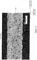
- FIG. 2 is a SEM image showing an example of a cross section that is vertical to the plate face of the positive electrode 106.
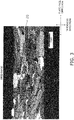
- FIG. 3 is an electron backscatter diffraction (EBSD) image in the cross section that is vertical to the plate face of the positive electrode 106.
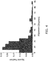
- FIG. 4 is a histogram using a surface area basis to illustrate the distribution of an orientation angle of the primary particles 20 in the EBSD image illustrated in FIG. 3 .
- EBSD electron backscatter diffraction
- the orientation angle of each primary particle 20 is categorized, such that the darker the color, the smaller the orientation angle.
- the orientation angle is the angle of inclination subtended by the (003) surface of each primary particle 20 relative to the plate face direction.
- the positions illustrated in black in the inner portion of the positive electrode 106 are pores.
- the positive electrode 106 is formed by bonding of a plurality of primary particles 20.
- Each primary particle 20 is formed mainly in a plate shape. However, a configuration such as rectangular, cubic and spherical or the like may also be included.
- a layered rock-salt structure is a crystalline structure in which a lithium layer and a transition metal layer other than lithium are alternately layered to sandwich an oxygen layer, that is to say, a crystalline structure in which a transition metal ion layer is alternatively layered with a lithium single layer through an oxide ion (typically, an ⁇ -NaFeO 2 type structure, that is to say, a structure in which a transition metal and lithium are regularly ordered in an [111] axial direction of a cubic crystal rock-salt structure).
- a lithium complex oxide for example includes Li x CoO 2 (lithium cobalt oxide), Li x NiO 2 (lithium nickelate), Li x MnO 2 (lithium manganate), Li x NiMnO 2 (nickel-lithium manganate), Li x NiCoO 2 (lithium-nickel-cobalt oxide), Li x CoNiMnO 2 (lithium cobalt nickel manganate), Li x CoMnO 2 (cobalt-lithium manganate), with Li x CoO 2 in particular being preferred.
- a lithium complex oxide may include one or more elements of Mg, Al, Si, Ca, Ti, V, Cr, Fe, Cu, Zn, Ga, Ge, Sr, Y, Zr, Nb, Mo, Ag, Sn, Sb, Te, Ba, Bi, W or the like.
- the average value of the orientation angle of each primary particle 20 (referred to below as “average orientation angle") is more than 0° and less than or equal to 30°.
- each primary particle 20 is nestled in a direction that is inclined towards the thickness direction, the adhesion between each of the primary particles can be enhanced. As a result, the rate characteristics are improved since the lithium ion conductivity is enhanced between a given primary particle 20 and another primary particle 20 that is adjacent on both longitudinal sides of the first primary particle 20.
- the cycle characteristics are enhanced.
- This feature is due to the fact that since each primary particle 20 is compressed in a direction that is perpendicular to the (003) plane in response to the intercalation and deintercalation of lithium ions, the expansion-contraction amount of the positive electrode 106 in the plate face direction is reduced as a result of the reduction in the angle of the (003) plane relative to the plate face direction and therefore it is possible to inhibit production of stress between the positive electrode 106 and the solid electrolyte layer 107.
- the average orientation angle of the primary particles 20 is obtained by the following method. Firstly, as illustrated in FIG. 3 , in the EBSD image in which a rectangular region of 95 ⁇ m ⁇ 125 ⁇ m is observed at 1000-fold magnification, three horizontal lines that divide the positive electrode 106 into 4 equal parts in the thickness direction and three vertical lines that divide the positive electrode 106 into 4 equal parts in the plate face direction are drawn. Then, the arithmetic mean of orientation angles is calculated for all primary particles 20 that intersect at least one line of the three horizontal lines and three vertical lines to thereby obtain an average orientation angle of the primary particles 20.
- the average orientation angle of the primary particles 20 is preferably less than or equal to 30°, and more preferably less than or equal to 25°.
- the average orientation angle of the primary particles 20 when the rate characteristics are considered in the same manner is preferably greater than or equal to 2°, and more preferably greater than or equal to 5°.
- the orientation angle of each primary particle 20 may exhibit a broad distribution from 0° to 90°. However, it is preferred that the majority is distributed in a region of more than 0° to less than or equal to 30°.
- the aggregate surface area of primary particles 20 that have an orientation angle of more than 0° to less than or equal to 30° is preferably greater than or equal to 70% relative to the total area of the 30 primary particles 20 used in the calculation of the average orientation angle.
- the aggregate surface area of the primary particles 20 that have an orientation angle of more than 0° to less than or equal to 30° relative to the plate face of the positive electrode 106 is greater than or equal to 70% when compared to the total area of the primary particles 20 contained in the cross section being analyzed.
- the aggregate surface area of configurations in which the orientation angle is less than or equal to 10° of the low angle primary particles is greater than or equal to 15% relative to the total area of the 30 primary particles 20 used in the calculation of the average orientation angle.
- the aggregate surface area of primary particles having an aspect ratio of greater than or equal to 4 of the 30 primary particles 20 used in the calculation of the average orientation angle is preferably greater than or equal to 70% relative to the total area of the 30 primary particles used in the calculation of the average orientation angle.
- the aspect ratio of the primary particles 20 is a value obtained by dividing the maximum Feret diameter by the minimum Feret diameter of the primary particles.
- a maximum Feret diameter is the maximum distance between straight lines when two parallel straight lines are drawn to sandwich primary particles 20 on an EBSD image for observation of a cross section.
- a minimum Feret diameter is the minimum distance between straight lines when two parallel straight lines are drawn to sandwich primary particles 20 on an EBSD image.
- the surface area ratio of primary particles 20 having an aspect ratio of greater than or equal to 4 of the 30 primary particles 20 used in the calculation of the average orientation angle is more preferably more than 70%, and particularly preferably greater than or equal to 80%.
- the rate characteristics are further enhanced since lithium ion conductivity is enhanced overall due to a reduction in the number of grain boundaries between primary particles 20 in the direction of lithium ion conduction.
- the average particle diameter of the primary particles 20 is a value obtained as the arithmetic mean of the equivalent circle diameter of each primary particle 20.
- the equivalent circle diameter is the diameter of a circle having the same surface area as each primary particle 20 in the EBSD image.
- the average particle diameter of the 30 primary particles 20 that are used in the calculation of the average orientation angle is preferably greater than or equal to 7 ⁇ m, and particularly preferred to be greater than or equal to 12 ⁇ m.
- the proportion of primary particles 20 in which the orientation angle difference is less than or equal to 40° is preferably greater than or equal to 50%, more preferably greater than or equal to 60% and particularly preferably greater than or equal to 70%.
- the denseness of the positive electrode 106 is more preferably greater than or equal to 80%, and particularly preferably greater than 90%.
- each pore formed in an inner portion of the positive electrode 106 may be an open pore that is connected with an external portion of the positive electrode 106, it is preferred that the pore does not penetrate the positive electrode 106. That is to say, it is preferred that each pore does not connect the solid electrolyte-side surface 106a of the positive electrode 106 with the current collecting connection layer-side surface 106b. Each pore may be a closed pore.
- An LiCoO 2 powder is synthesized by mixing a Li 2 CO 3 starting powder with a Co 3 O 4 starting powder and firing (500 ⁇ to 900 ⁇ , 1 to 20 hours).
- Plate-shaped LiCoO 2 particles that enable conduction of lithium ions parallel to the plate face are obtained by grinding the resulting LiCoO 2 powder using a ball mill to have a volume-based D50 particle diameter of 0.1 ⁇ m to 10 ⁇ m.
- the resulting LiCoO 2 particles exhibit a configuration of tending to cleave along a cleavage plane.
- the LiCoO 2 template particles are prepared by cracking and cleaving the LiCoO 2 particles.
- the aggregate surface area ratio of the low angle primary particles having an orientation angle of greater than 0° and less than or equal to 30° by adjusting at least one of the particle diameter and the aspect ratio of the LiCoO 2 template particles. More specifically, the aggregate surface area ratio of the low angle primary particles can be increased as the aspect ratio of the LiCoO 2 template particles is increased, or as the particle diameter of the LiCoO 2 template particles is increased.
- the respective particle diameter and aspect ratio of the LiCoO 2 template particles can be adjusted by at least one of the particle diameter of the Li 2 CO 3 starting powder and the Co 3 O 4 starting powder, the milling conditions during milling (milling time, milling energy, milling method or the like), and the classification conducted after milling.
- the aggregate surface area ratio of the primary particles 20 having an aspect ratio of greater than or equal to 4 can be controlled by adjusting the aspect ratio of the LiCoO 2 template particles. More specifically, the aggregate surface area ratio of the primary particles 20 having an aspect ratio of greater than or equal to 4 can be increased as the aspect ratio of the LiCoO 2 template particles is increased.
- the method of adjusting the aspect ratio of the LiCoO 2 template particles has been described above.
- the denseness of the positive electrode 106 by adjusting the particle diameter of the LiCoO 2 template particles. More specifically, the denseness of the positive electrode 106 increases as the particle diameter of the LiCoO 2 template particles is reduced.
- a Co 3 O 4 starting powder is used as matrix particles.
- the volume-based D50 particle diameter of the Co 3 O 4 starting material powder may be 0.1 to 1.0 ⁇ m. It is preferred that it is smaller than the volume-based D50 particle diameter of the LiCoO 2 template particles.
- the matrix particles can be obtained by thermal processing of the Co(OH) 2 starting material for 1 to 10 hours at 500°C to 800°C. Furthermore, in addition to Co 3 O 4 , Co(OH) 2 particles, or LiCoO 2 particles may be used in the matrix particles.
- the aggregate surface area ratio of the low angle primary particles that have an orientation angle of more than 0° and less than or equal to 30° can be controlled by adjusting the ratio of the particle diameter of the matrix particles relative to the particle diameter of the LiCoO 2 template particles (referred to below as “matrix/template particle diameter ratio"). More specifically, as the matrix/template particle diameter ratio becomes smaller, that is to say, as the particle diameter of the matrix particles becomes small, since there is a tendency for the matrix particles in the firing step described below to be incorporated in the LiCoO 2 template particles, the aggregate surface area ratio of the low angle primary particles can be increased.
- the aggregate surface area ratio of the primary particles 20 having an aspect ratio of greater than or equal to 4 can be increased as the matrix/template particle diameter ratio is reduced, that is to say, as the particle diameter of the matrix particles is reduced.
- the denseness of the positive electrode 106 can be controlled by adjusting the matrix/template particle diameter ratio. More specifically, as the matrix/template particle diameter ratio becomes small, that is to say, as the particle diameter of the matrix particles becomes small, the denseness of the positive electrode 106 can be increased.
- a powder containing a mixture of LiCoO 2 template particles and matrix particles in a proportion of 100:3 ⁇ 3:97, a dispersing medium, a binder, a plasticizer, and a dispersing agent are mixed. Under reduced pressure, stirring and degassing are performed, and the mixture is adjusted to a desired viscosity to thereby prepare a slurry.
- an average orientation angle for each primary particle 20 can be configured to be more than 0° and less than or equal to 30°.
- the present step as described below enables control of the profile of the primary particles 20 that configure the positive electrode 106.
- the aggregate surface area ratio of the low angle primary particles that have an orientation angle of more than 0° and less than or equal to 30° can be controlled by adjusting the molding speed. More specifically, as the molding speed increases, the aggregate surface area ratio of the low angle primary particles can be increased.
- the denseness of the positive electrode 106 can also be controlled by adjusting the mixing ratio of the LiCoO 2 template particles and matrix particles. More specifically, as the number of LiCoO 2 template particles increases, the denseness of the positive electrode 106 can be reduced.
- the green body of the slurry is placed into a zirconia setter and subjected to thermal processing (500°C to 900°C, 1 to 10 hours) to thereby obtain a sintered plate as an intermediate body.
- the sintered plate is sandwiched from the top and the bottom by a lithium sheet so that the synthesized lithium sheet has an Li/Co ratio of 1.0, and placed on a zirconia setter.
- the Li/Co ratio may be in excess by about 0.1 to 1.5.
- Grain growth is promoted by reason of the Li/Co ratio being in excess by more than 1.0.
- the behavior of the grain growth can be controlled by changing the material and denseness of the setter. For example, grain growth can be promoted by use of a dense magnesia setter that tends not to react with lithium.
- the setter is placed in an alumina sheath and after firing in air (700°C to 850°C, 1 to 20 hours), the sintered plate is sandwiched on the top and the bottom by a lithium sheet, and subjected to further firing (750°C to 900°C, 1 to 40 hours) to thereby obtain an LiCoO 2 sintered plate.
- the firing step may be separated into two steps, or may be performed on a single occasion. When firing is performed twice, the first firing temperature is preferably lower than the second firing temperature.
- the present step as described below enables control of the profile of the primary particles 20 that configure the positive electrode 106.
- the aggregate surface area ratio of the low angle primary particles that have an orientation angle of more than 0° and less than or equal to 30° can be controlled by adjusting the rate of temperature increase during firing. More specifically, as the rate of increase in temperature increases, sintering between matrix particles is suppressed and the aggregate surface area ratio of the low angle primary particles can be increased.
- At least one of the Li (for example, Li 2 CO 3 ) amount during firing and the sintering additive (for example, boric acid, bismuth oxide) amount can be adjusted to thereby control the average particle diameter of the primary particles 20. More specifically, as the amount of Li increases, or as the amount of the sintering additive increases, the average particle diameter of the primary particles 20 can be increased.
- the denseness of the positive electrode 106 can be controlled by adjusting the profile during firing. More specifically, as the firing temperature is lowered, or as the firing time is increased, the denseness of the positive electrode 106 can be increased.
- the positive electrode according to the present invention can be used in a lithium ion battery using an electrolyte such as an ionic liquid electrolyte, a polymer electrolyte, a gel electrolyte, or a liquid electrolyte.
- An ionic liquid electrolyte solution comprises an ionic liquid cation, an ionic liquid anion and an electrolyte.
- the ionic liquid cation includes a 1-ethyl-3-methylimidazolium cation (EMI), a 1-methyl-1-propylpyrrolidinium cation (P13), 1-methyl-1-propylpiperidinium cation (PP13), and derivatives and arbitrary combinations thereof.
- EMI 1-ethyl-3-methylimidazolium cation
- P13 1-methyl-1-propylpyrrolidinium cation
- PP13 1-methyl-1-propylpiperidinium cation
- a Co 3 O 4 starting material powder (volume-based D50 particle diameter 0.8 ⁇ m, manufactured by Seido Chemical Industry Co., Ltd.) and Li 2 CO 3 starting material powder (volume-based D50 particle diameter 2.5 ⁇ m, manufactured by Honjo Chemical Corporation) were mixed and fired for 5 hours at 800°C to synthesize a LiCoO 2 starting material powder. At that time, the firing temperature or firing time was adjusted to thereby adjust the volume-based D50 particle diameter of the LiCoO 2 starting material powder to the values shown in Table 1.
- Plate-shaped LiCoO 2 particles were obtained by grinding the resulting LiCoO 2 powder.
- Examples 1 and 2 and 4 to 8 used a pot mill, and Example 3 used a wet jet mill. At this time, the grinding time was adjusted to thereby adjust the volume-based D50 particle diameter of the LCO template particles to the values shown in Table 1.
- the aspect ratio of the LiCoO 2 template particles is shown in Table 1.
- the aspect ratio of LiCoO 2 template particles was measured by using SEM to observe the resulting template particles.
- a Co 3 O 4 starting material powder (manufactured by Seido Chemical Industry Co., Ltd.) was used as a matrix particle.
- the volume-based D50 particle diameter of the matrix particles is shown in Table 1. However, in Example 4, a matrix particle was not used.
- a binder polyvinyl butyral: No. BM-2, manufactured by Sekisui Chemical Co., Ltd.
- a plasticizer DOP: di(2-ethylhexyl) phthalate manufactured by Kurogane Kasei Co., Ltd.
- a dispersing agent product name: RHEODOL SP-O30, manufactured by Kao Corporation
- the Co 3 O 4 sintered plate was obtained by placing the green sheet that was peeled from the PET film in a zirconia setter and performing primary firing. As shown in Table 1, the firing conditions in Examples 1 to 6 and 8 were 900°C and 5 hours and in Example 7, 800°C and 5 hours.
- the LiCoO 2 sintered plate was obtained by causing the Li/Co ratio of the synthesized lithium sheet to coincide with the ratio shown Table 1 by sandwiching the Co 3 O 4 sintered plate from the top and the bottom by a lithium sheet, placing on a zirconia setter and performing secondary firing. More specifically, a zirconia setter is placed in a 90 mm square alumina sheath, and after retaining in air at 800°C for 5 hours, further sandwiching is performed from the top and the bottom by a lithium sheet and firing is performed at 900°C for 20 hours.
- a 500 ⁇ Au film was formed on the solid electrolyte layer by sputtering using an ion sputtering apparatus (JFC-1500 manufactured by JEOL Ltd).
- a tungsten boat loaded with lithium metal was prepared.
- a vacuum vapor deposition apparatus carbon coater SVC-700 manufactured by Sanyu Electron Co., Ltd.
- carbon coater SVC-700 manufactured by Sanyu Electron Co., Ltd.
- a mask was used to form the size of the negative electrode layer as 9.5 mm square and so that the negative electrode layer was restricted to within the 10 mm square positive electrode region.
- a unit battery was prepared by forming an Li deposition film having a film thickness of 10 ⁇ m as a negative electrode on the solid electrolyte layer.
- a positive electrode current collection plate was formed by cutting out stainless steel foil having a thickness of 20 ⁇ m into 13 mm square. Furthermore, a frame-shaped modified polypropylene resin film (thickness 100 ⁇ m) having a width of 1 mm was prepared by punching holes that are13 mm square on an outer edge and 11 mm square on an inner side. The frame-shaped resin film was stacked on an outer peripheral portion of the positive-electrode current collection plate and subjected to thermal press bonding to thereby form an end sealing portion. The unit battery was placed in a region surrounded by the end sealing portion on the positive-electrode current collection plate.
- Stainless steel foil having a thickness of 20 ⁇ m was placed in the same manner as described above on the negative electrode side of the disposed unit battery, and while a load was applied to the end sealing portion, heating was applied at 200°C under reduced pressure. In this manner, the upper and lower two layers of stainless steel foil and the end sealing portion were bonded along the entire outer periphery to thereby seal the unit battery. In this manner, a totally solid lithium battery was obtained in a sealed state.
- Comparative Example 1 the LiCoO 2 powder is not pulverized, and therefore with the exception of using the LCO template particles without modification, a solid lithium battery was obtained using the same processing steps as those described in Examples 1 to 8.
- Comparative Example 2 With the exception that the volume-based D50 particle diameter of the CoO matrix particles is greater than that used in Examples 1 to 8, a solid lithium battery was obtained using the same processing steps as those described in Examples 1 to 8.
- the volume-based D50 particle diameter of the matrix particles in Comparative Example 2 was 3.0 ⁇ m, and the particle diameter ratio of the LCO template particles relative to the CoO matrix particles was 0.2.
- Example 5 the slurry prepared in Example 1 is not formed in a sheet shape and is dried without modification. After firing the dried article in the same manner as Example 1, #1200 SiC abrasive paper is used to grind to a thickness of 40 ⁇ m and thereby obtain a positive electrode plate. The positive electrode plate is used to obtain a solid lithium battery in the same manner as Example 1.
- a scanning electron microscope JSM-7800M manufactured by JEOL Ltd.
- JSM-7800M manufactured by JEOL Ltd.
- the average orientation angle of the primary particles was calculated by taking the arithmetic mean of the orientation angle of 30 primary particles that are arbitrarily selected on the EBSD image. The calculation results are shown in Table 2.
- the surface area ratio was calculated for the primary particles having an aspect ratio greater than or equal to 4 in the EBSD image from among the 30 primary particles used in the calculation of the average orientation angle. The calculation results are shown in Table 2.
- Example 1 3.0 ⁇ m Ball Mill 0.6 ⁇ m 5 0.3 ⁇ m 50:50 2.0 100 m/h 40 ⁇ m 900°C 1.05 800°C 900°C 200°C/h
- Example 2 10.0 ⁇ m Ball Mill 2.2 ⁇ m 10 0.3 ⁇ m 50:50 7.3 100 m/h 40 ⁇ m 900°C 1.05 800°C 900°C 200°C/h
- Example 3 30 ⁇ m Wet jet mill 1.3 ⁇ m 15 0.3 ⁇ m 50:50 4.3 100 m/h 40 ⁇ m 900°C 1.05 800°C 900°C 200°C/h
- Example 4 3.0 ⁇ m Ball Mill 0.6 ⁇ m 5 - 100:0 - 100 m/h 40 ⁇ m 900°C 1.2 800°C 900°C 200°C/h
- Example 5 3.0 ⁇ m Ball Mill 0.6 ⁇ m 5 0.3 ⁇ m 10:90
Landscapes
- Chemical & Material Sciences (AREA)
- Engineering & Computer Science (AREA)
- Manufacturing & Machinery (AREA)
- Ceramic Engineering (AREA)
- Chemical Kinetics & Catalysis (AREA)
- Electrochemistry (AREA)
- General Chemical & Material Sciences (AREA)
- Organic Chemistry (AREA)
- Materials Engineering (AREA)
- Inorganic Chemistry (AREA)
- Structural Engineering (AREA)
- Battery Electrode And Active Subsutance (AREA)
- Secondary Cells (AREA)
Abstract
Description
- The present invention relates to a method for manufacturing a positive electrode.
- A typical positive electrode for a lithium ion battery is a positive electrode which is configured by bonding of a plurality of primary particles composed of a lithium composite oxide having a layered rock-salt structure.
- In Patent Literature 1, a method of manufacturing a positive electrode has been proposed for the purpose of exposing a crystal plane facilitating intercalation and deintercalation of lithium ions (a plane other than the crystal plane (003), for example, the (101) plane or the (104) plane) to a surface of the positive electrode (referred to below as a "plate face") and which includes a step of forming a thin film sheet containing plate-shaped Co3O4 particles in which the (h00) face is oriented in parallel to the surface, and a step of introducing Li to the Co3O4 particles.
- According to the method of manufacture disclosed in Cited Reference 1, the orientation direction of each of the primary particles exposed on the plate surface can be configured as a [101] direction or a [104] direction. When the orientation direction of the primary particles is the [101] direction, the (003) plane of the primary particles can be configured to tilt at about 75 degrees with respect to the plate surface. If the orientation direction of the primary particles is the [104] direction, the (003) plane of the primary particles can be configured to tilt at about 48 degrees with respect to the plate surface.
- [Patent Literature 1]
PCT Laid Open Application 2010/074304 - In this regard, as a result of the diligent research conducted by the present inventors, the new insight has been gained that it is preferred to reduce the angle of inclination of the (003) plane of the primary particles relative to the plate face in order to enhance the rate characteristics of the positive electrode.
- However, it is not a simple task to reduce the angle of inclination of the (003) plane of the primary particles relative to the plate face in the manufacturing method disclosed in Cited Reference 1.
- The present invention is proposed based on the new insight above, and has the object of providing a manufacturing method for a positive electrode that enables the angle of inclination of the (003) plane of the primary particles to be reduced relative to the plate face.
- The method for manufacturing a positive electrode according to the present invention includes a step of forming plate-shaped LiCoO2 template particles that are configured to conduct lithium ions parallel to a plate face, a step of molding a green body by forming a slurry containing LiCoO2 template particles by use of a molding method configured to enable application of a shear force to the LiCoO2 template particles, and a step of firing the green body.
- The present invention provides a manufacturing method for a positive electrode that enables the angle of inclination of the (003) plane of the primary particles to be reduced relative to the plate face.
-
-
FIG. 1 is a cross sectional view schematically illustrating a configuration of a lithium ion battery. -
FIG. 2 is an SEM image showing an example of a cross section that is vertical to the plate face of the positive electrode. -
FIG. 3 is an EBSD image in the cross section of the positive electrode illustrated inFIG. 2 . -
FIG. 4 is a histogram using a surface area basis to illustrate the distribution of an orientation angle of primary particles in the EBSD image illustrated inFIG. 3 . Description of Embodiments -
FIG. 1 is a cross sectional view illustrating a configuration of a lithium ion battery. A chip-type lithium battery 100 configured as a plate piece is a secondary battery (rechargeable battery) that is capable of repetitive use as a result of charging and discharging. - The
lithium battery 100 comprises a positive electrode-side current collectinglayer 101, a negative electrode-sidecurrent collecting layer 102,outer cladding collecting connection layer 105, apositive electrode 106, asolid electrolyte layer 107 and thenegative electrode layer 108. Thelithium ion battery 100 has a configuration in which the positive electrode-side current collectinglayer 101, the currentcollecting connection layer 105, thepositive electrode 106, thesolid electrolyte layer 107, thenegative electrode layer 108 and the negative electrode-sidecurrent collecting layer 102 are sequentially stacked in a stacking direction X. - An end portion in the direction of plate width of the
lithium ion battery 100 is sealed by theouter cladding positive electrode portion 110 is configured by the positive electrode-side current collectinglayer 101, the currentcollecting connection layer 105 and thepositive electrode 106. Anegative electrode portion 120 is configured by the negative electrode-side current collectinglayer 102 and thenegative electrode layer 108. - The positive electrode-side
current collecting layer 101 is disposed on an outer side of thepositive electrode 106. The positive electrode-side current collectinglayer 101 is mechanically and electrically connected through the currentcollecting connection layer 105 to thepositive electrode 106. The positive electrode-side current collectinglayer 101 can function as a positive electrode current collector. - The positive electrode-side current collecting
layer 101 can be composed of metal. The metal that configures the positive electrode-side current collectinglayer 101 includes stainless steel, aluminum, copper, platinum, nickel and the like, with aluminum, nickel and stainless steel being particularly suitable. The positive electrode-side current collectinglayer 101 may be formed in a plate shape or a foil shape, with a foil shape being particularly preferred. Therefore, use of an aluminum foil, a nickel foil, or a stainless steel foil is particularly preferred as the positive electrode-side current collectinglayer 101. When the positive electrode-side current collectinglayer 101 is shaped as a foil, the thickness of the positive electrode-sidecurrent collecting layer 101 may be configured to 1 to 30 µm, preferably as greater than or equal to 5 and less than or equal to 25 µm, and more preferably as greater than or equal to 10 and less than or equal to 20 µm. - The negative electrode-side
current collecting layer 102 is disposed on an outer side of thenegative electrode layer 108. The negative electrode-side current collectinglayer 102 is mechanically and electrically connected to thenegative electrode layer 108. The negative electrode-side current collectinglayer 102 can function as a negative electrode current collector. The negative electrode-side current collectinglayer 102 can be composed of metal. The negative electrode-side current collectinglayer 102 can be composed of the same material as the positive electrode-side current collectinglayer 101. Therefore use is preferred of an aluminum foil, a nickel foil, or a stainless steel foil as the negative electrode-sidecurrent collecting layer 102. When the negative electrode-sidecurrent collecting layer 102 is shaped as a foil, the thickness of the negative electrode-sidecurrent collecting layer 102 may be configured to 1 to 30 µm, preferably as greater than or equal to 5 and less than or equal to 25 µm, and more preferably as greater than or equal to 10 and less than or equal to 20 µm. - The
outer cladding layer 101 and the negative electrode-side current collectinglayer 102. Theouter cladding positive electrode 106, thesolid electrolyte layer 107 and thenegative electrode layer 108. Theouter cladding lithium ion battery 100. - In order to ensure electrical insulation between the positive electrode-side current collecting
layer 101 and the negative electrode-side current collectinglayer 102, the resistivity of theouter cladding outer cladding outer cladding lithium ion battery 100 due to heat. - The
outer cladding - The current
collecting connection layer 105 is disposed between the positive electrode-side current collectinglayer 101 and thepositive electrode 106. The currentcollecting connection layer 105 mechanically bonds thepositive electrode 106 to the positive electrode-side current collectinglayer 101 and electrically bonds thepositive electrode 106 to the positive electrode-side current collectinglayer 101. - The current
collecting connection layer 105 includes a conductive material and an adhesive. The conductive material may include use of conductive carbon or the like. The adhesive may include use of an epoxy or the like. Although there is no particular limitation in relation to the thickness of the currentcollecting connection layer 105, it may be configured as greater than or equal to 5 µm and less than or equal to 100 µm, and preferably greater than or equal to 10 µm and less than or equal to 50 µm. - However the current
collecting connection layer 105 may omit the adhesive. - In this configuration, an electrical connection between the
positive electrode 106 and the currentcollecting connection layer 105 may be created by configuring the currentcollecting connection layer 105 as a direct connection film (for example, gold or aluminum) on the rear surface of thepositive electrode 106. - The
positive electrode 106 is formed in a plate shape. Thepositive electrode 106 includes a solid electrolyte-side surface 106a and a current collecting connection layer-side surface 106b. Thepositive electrode 106 is connected to thesolid electrolyte layer 107 on the solid electrolyte-side surface 106a. Thepositive electrode 106 is connected to the currentcollecting connection layer 105 on the current collecting connection layer-side surface 106b. The solid electrolyte-side surface 106a and the current collecting connection layer-side surface 106b respectively form a "plate face" of thepositive electrode 106. Upon observation of a cross section of thepositive electrode 106 by use of a scanning electron microscope (SEM), the solid electrolyte-side surface 106a is an approximately straight line obtained by a least squares method defining the interface between thepositive electrode 106 and thesolid electrolyte layer 107. Upon observation of a cross section of thepositive electrode 106 by SEM, the current collecting connection layer-side surface 106b is an approximately straight line obtained by a least squares method defining the interface between thepositive electrode 106 and the currentcollecting connection layer 105. - A processing operation such as polishing or the like may be applied to the solid electrolyte-
side surface 106a of thepositive electrode 106. In this manner, even in a configuration in which the film thickness of thesolid electrolyte layer 107 is reduced as a result of a change in the surface configuration of the solid electrolyte-side surface 106a, it is possible to inhibit a reduction in the film properties of thesolid electrolyte layer 107. The means of varying the surface configuration of the solid electrolyte-side surface 106a is not limited to a polishing processing operation, and the surface configuration of the solid electrolyte-side surface 106a may also be changed as a result of a method of coating and firing a microparticle active material, or a means of forming thesolid electrolyte layer 107 by a gas phase method such as sputtering or the like. - Although there is no particular limitation in relation to the thickness of the
positive electrode 106, it may be configured as greater than or equal to 20 µm, preferably greater than or equal to 25 µm, and more preferably greater than or equal to 30 µm. In particular, a configuration in which the thickness of thepositive electrode 106 is greater than or equal to 50 µm makes it possible to increase the energy density of thelithium ion battery 100 by ensuring a sufficient active material capacity per unit surface area. Furthermore although there is no particular limitation on the upper limiting value of the thickness of thepositive electrode 106, when inhibiting the deterioration of battery characteristics (in particular an increase in the resistance value) that results from repetitive charging and discharging is taken into account, a value of less than 200 µm is preferred, a value of less than or equal to 150 µm is more preferred, a value of less than or equal to 120 µm is still more preferred, and a value of less than or equal to 100 µm is particularly preferred - When a cross section of the
positive electrode 106 is observed by SEM, the thickness of thepositive electrode 106 is obtained by measurement of the average distance (average value of a distance at 3 arbitrary points) in the thickness direction of the solid electrolyte-side surface 106a and the current collecting connection layer-side surface 106b. The thickness direction is a direction that is vertical in relation to the solid electrolyte-side surface 106a and the current collecting connection layer-side surface 106b and is substantially the same as the stacking direction X. - A coefficient of expansion-contraction in a direction parallel to the plate face of the positive electrode 106 (referred to below as "plate face direction") is preferably suppressed to less than or equal to 0.7%. In this manner, when the coefficient of expansion-contraction of the
positive electrode 106 is sufficiently low, even when the thickness of thepositive electrode 106 is configured to be less than or equal to 30 µm for the purpose of enhancing the rate characteristics of thelithium ion battery 100, it is possible to inhibit peeling of thepositive electrode 106 and/or a defect in thesolid electrolyte layer 107. Therefore the thickness of thepositive electrode 106 may be suitably set taking into account the coefficient of expansion-contraction of thepositive electrode 106 and the discharge capacity of thelithium ion battery 106. - The microstructure of the
positive electrode 106 will be discussed below. - The
solid electrolyte layer 107 is preferably composed of a lithium phosphate oxynitride (LiPON) ceramic material that is known to be an oxide-based ceramic material. The thickness of thesolid electrolyte layer 107 preferably has a thin configuration to thereby enhance lithium ion conductivity, and may be suitably set by taking into account reliability during charging and discharging (cracking, separator function, inhibiting a defect or the like). The thickness of thesolid electrolyte layer 107 for example is preferably 0.1 to 10 µm, more preferably 0.2 to 8.0 µm, still more preferably 0.3 to 7.0 µm, and particularly preferably 0.5 to 6.0 µm. - A sputtering method is preferably used as a method of film formation for attaching the
solid electrolyte layer 107 that is formed from a ceramic material to the solid electrolyte-side surface 106a of thepositive electrode 106. At that time, the thickness of thesolid electrolyte layer 107 can be adjusted by controlling the film formation conditions (for example, film formation time) used in the sputtering method. Thepositive electrode 106 does not tend to cause a defect in battery function even when the battery is configured by forming a solid electrode layer composed of LiPON on the surface by use of a sputtering method. - LiPON is a group of compounds represented by a composition of Li2.9PO3.3N0.46, and for example, is a group of compounds represented by LiaPObNc (wherein, a is 2 to 4, b is 3 to 5, and c is 0.1 to 0.9). Therefore, the formation of a LiPON-based solid electrolyte layer by sputtering may be performed using a lithium phosphate sintered body target as an Li source, a P source and an O source, and carried out according to known conditions by introducing N2 as a gas species for the N source. Although there is no particular limitation on the sputtering method, use of an RF magnetron method is preferred. Furthermore, in substitution for the sputtering method, a film formation method such as an MOCVD method, a sol gel method, an aerosol deposition method, a screen printing or the like may be used.
- The
solid electrolyte layer 107 may be composed of an oxide-based ceramic material other than a LiPON-based ceramic material. The oxide-based ceramic material other than a LiPON-based ceramic material includes at least one type selected from the group consisting of a garnet-based ceramic material, a nitride-based ceramic material, a perovskite-based ceramic material, a phosphate-based ceramic material and a zeolite-based ceramic material. An example of the garnet ceramic material includes use of an Li-La-Zr-O-based material (specifically Li7La3Zr2O12, or the like) and an Li-La-Ta-O-based material. An example of the perovskite-based ceramic material includes use of an Li-La-Ti-O-based material (specifically LiLa1-xTixO3 (0.04≦x≦ 0.14), or the like). An example of the phosphate-based ceramic material includes use of Li-Al-Ti-P-O, Li-Al-Ge-P-O and Li-Al-Ti-Si-P-O (specifically Li1+x+yAlxTi2-xSiy P3-yO12 (0≦x≦0.4, 0≦y≦0.6) or the like). - The
solid electrolyte layer 107 may also be composed of a sulfide based material. The sulfide based material includes use of a material selected from a solid electrolyte based on Li2S-P2S5, LiI-Li2S-P2S5, LiI-Li2S-B2S32, or LiI-Li2S-SiS2, Thio-LISICON, and Li10GeP2S12, or the like. A sulfide based material is comparatively soft, and therefore the battery can be configured by forming a solid electrolyte layer by compaction using a press of a sulfide-based powder onto the surface of thepositive electrode 106. More specifically, the solid electrolyte layer can be formed by stacking and pressing a sulfide-based powder body configured in a sheet shape by using a binder or the like onto thepositive electrode 106, or by a pressing operation after coating and drying a slurry in which a sulfide-based powder is dispersed onto thepositive electrode 106. - The
negative electrode layer 108 is disposed on thesolid electrolyte layer 107. Thenegative electrode layer 108 contains a principal component of lithium metal. Thenegative electrode layer 108 may be configured as a lithium-containing metal film formed on thesolid electrolyte layer 107. The lithium-containing metal film may be formed by a vacuum deposition method, a sputtering method, a CVD method, or the like. - Although there is no particular limitation on the thickness of the
negative electrode layer 108, it may be configured as less than or equal to 200 µm. When the feature of increasing the energy density and ensuring a large total lithium amount in thelithium battery 100 is taken into account, it is preferred that the thickness of thenegative electrode layer 108 is greater than or equal to 10 µm, preferably greater than or equal to 10 µm and less than or equal to 50 µm, more preferably greater than or equal to 10 µm and less than or equal to 40 µm, and particularly preferably greater than or equal to 10 µm and less than or equal to 20 µm. -
FIG. 2 is a SEM image showing an example of a cross section that is vertical to the plate face of thepositive electrode 106.FIG. 3 is an electron backscatter diffraction (EBSD) image in the cross section that is vertical to the plate face of thepositive electrode 106.FIG. 4 is a histogram using a surface area basis to illustrate the distribution of an orientation angle of theprimary particles 20 in the EBSD image illustrated inFIG. 3 . - In the EBSD image illustrated in
FIG. 3 , a discontinuity in the crystal orientation can be observed. InFIG. 3 , the orientation angle of eachprimary particle 20 is categorized, such that the darker the color, the smaller the orientation angle. The orientation angle is the angle of inclination subtended by the (003) surface of eachprimary particle 20 relative to the plate face direction. InFIG. 2 andFIG. 3 , the positions illustrated in black in the inner portion of thepositive electrode 106 are pores. - The
positive electrode 106 is formed by bonding of a plurality ofprimary particles 20. Eachprimary particle 20 is formed mainly in a plate shape. However, a configuration such as rectangular, cubic and spherical or the like may also be included. There is no particular limitation on the cross sectional shape of eachprimary particle 20, and it may be oblong, a polygonal shape other than oblong, circular, oval, or another complex shape in addition to the above shapes. - Each
primary particle 20 is composed of a lithium complex oxide. A lithium complex oxide is an oxide that is expressed as LixMO2 (wherein 0.05<x<1.10, and wherein M is at least one type of transition metal, and M typically includes one or more types of Co, Ni, Mn). A lithium complex oxide has a layered rock-salt structure. A layered rock-salt structure is a crystalline structure in which a lithium layer and a transition metal layer other than lithium are alternately layered to sandwich an oxygen layer, that is to say, a crystalline structure in which a transition metal ion layer is alternatively layered with a lithium single layer through an oxide ion (typically, an α-NaFeO2 type structure, that is to say, a structure in which a transition metal and lithium are regularly ordered in an [111] axial direction of a cubic crystal rock-salt structure). - A lithium complex oxide for example includes LixCoO2 (lithium cobalt oxide), LixNiO2 (lithium nickelate), LixMnO2 (lithium manganate), LixNiMnO2 (nickel-lithium manganate), LixNiCoO2 (lithium-nickel-cobalt oxide), LixCoNiMnO2 (lithium cobalt nickel manganate), LixCoMnO2 (cobalt-lithium manganate), with LixCoO2 in particular being preferred.
- A lithium complex oxide may include one or more elements of Mg, Al, Si, Ca, Ti, V, Cr, Fe, Cu, Zn, Ga, Ge, Sr, Y, Zr, Nb, Mo, Ag, Sn, Sb, Te, Ba, Bi, W or the like.
- As illustrated in
FIG. 3 andFIG. 4 , the average value of the orientation angle of each primary particle 20 (referred to below as "average orientation angle") is more than 0° and less than or equal to 30°. - In this manner, since each
primary particle 20 is nestled in a direction that is inclined towards the thickness direction, the adhesion between each of the primary particles can be enhanced. As a result, the rate characteristics are improved since the lithium ion conductivity is enhanced between a givenprimary particle 20 and anotherprimary particle 20 that is adjacent on both longitudinal sides of the firstprimary particle 20. - As shown in the present embodiment, when the
positive electrode 106 is used in connection with thesolid electrolyte layer 107, the cycle characteristics are enhanced. This feature is due to the fact that since eachprimary particle 20 is compressed in a direction that is perpendicular to the (003) plane in response to the intercalation and deintercalation of lithium ions, the expansion-contraction amount of thepositive electrode 106 in the plate face direction is reduced as a result of the reduction in the angle of the (003) plane relative to the plate face direction and therefore it is possible to inhibit production of stress between thepositive electrode 106 and thesolid electrolyte layer 107. - Furthermore, as shown in the present embodiment, when the
positive electrode 106 is used in connection with thesolid electrolyte layer 107, the rate characteristics are further enhanced. As discussed above, this feature is due to the fact that during intercalation and deintercalation of lithium ions, the expansion-contraction of thepositive electrode 106 in the thickness direction predominates over that in the plate face direction resulting in smooth expansion-contraction of thepositive electrode 106, and consequently smooth intercalation and deintercalation of lithium ions. - The average orientation angle of the
primary particles 20 is obtained by the following method. Firstly, as illustrated inFIG. 3 , in the EBSD image in which a rectangular region of 95µm × 125µm is observed at 1000-fold magnification, three horizontal lines that divide thepositive electrode 106 into 4 equal parts in the thickness direction and three vertical lines that divide thepositive electrode 106 into 4 equal parts in the plate face direction are drawn. Then, the arithmetic mean of orientation angles is calculated for allprimary particles 20 that intersect at least one line of the three horizontal lines and three vertical lines to thereby obtain an average orientation angle of theprimary particles 20. - In consideration of the further enhancement in the rate characteristics, the average orientation angle of the
primary particles 20 is preferably less than or equal to 30°, and more preferably less than or equal to 25°. The average orientation angle of theprimary particles 20 when the rate characteristics are considered in the same manner is preferably greater than or equal to 2°, and more preferably greater than or equal to 5°. - As illustrated in
FIG. 4 , the orientation angle of eachprimary particle 20 may exhibit a broad distribution from 0° to 90°. However, it is preferred that the majority is distributed in a region of more than 0° to less than or equal to 30°. - In the EBSD image illustrated in
FIG. 3 , the aggregate surface area ofprimary particles 20 that have an orientation angle of more than 0° to less than or equal to 30° (referred to below as "low angle primary particles") is preferably greater than or equal to 70% relative to the total area of the 30primary particles 20 used in the calculation of the average orientation angle. In other words, when the cross section of thepositive electrode 106 is analyzed using EBSD, of thoseprimary particles 20 that are included in the cross section under analysis, it is preferred that the aggregate surface area of theprimary particles 20 that have an orientation angle of more than 0° to less than or equal to 30° relative to the plate face of thepositive electrode 106 is greater than or equal to 70% when compared to the total area of theprimary particles 20 contained in the cross section being analyzed. - In this manner, the rate characteristics can be further enhanced since the proportion of
primary particles 20 that exhibit high mutual adhesion is increased. - When further enhancement in the rate characteristics is taken into account, the aggregate surface area of low angle primary particles relative to the total area of the 30
primary particles 20 used in the calculation of the average orientation angle is preferably more than 70%, and still more preferably greater than or equal to 80%. - It is more preferred that the aggregate surface area of configurations in which the orientation angle of the low angle primary particles is less than or equal to 20° is greater than or equal to 50% relative to the total area of the 30
primary particles 20 used in the calculation of the average orientation angle. - Furthermore, it is more preferred that the aggregate surface area of configurations in which the orientation angle is less than or equal to 10° of the low angle primary particles is greater than or equal to 15% relative to the total area of the 30
primary particles 20 used in the calculation of the average orientation angle. - Each
primary particle 20 is formed in a plate shape, and therefore as illustrated inFIG. 2 andFIG. 3 , the cross section of eachprimary particle 20 extends in respectively predetermined directions. That is to say, the cross section of eachprimary particle 20 is formed in substantially an oblong shape. - The aggregate surface area of primary particles having an aspect ratio of greater than or equal to 4 of the 30
primary particles 20 used in the calculation of the average orientation angle is preferably greater than or equal to 70% relative to the total area of the 30 primary particles used in the calculation of the average orientation angle. - In this manner, the rate characteristics can be further enhanced since mutual adhesion between
primary particles 20 is further enhanced. - The aspect ratio of the
primary particles 20 is a value obtained by dividing the maximum Feret diameter by the minimum Feret diameter of the primary particles. A maximum Feret diameter is the maximum distance between straight lines when two parallel straight lines are drawn to sandwichprimary particles 20 on an EBSD image for observation of a cross section. A minimum Feret diameter is the minimum distance between straight lines when two parallel straight lines are drawn to sandwichprimary particles 20 on an EBSD image. - The surface area ratio of
primary particles 20 having an aspect ratio of greater than or equal to 4 of the 30primary particles 20 used in the calculation of the average orientation angle is more preferably more than 70%, and particularly preferably greater than or equal to 80%. - The average particle diameter of the 30
primary particles 20 used in the calculation of the average orientation angle is preferably greater than or equal to 5 µm. - In this manner, the rate characteristics are further enhanced since lithium ion conductivity is enhanced overall due to a reduction in the number of grain boundaries between
primary particles 20 in the direction of lithium ion conduction. - The average particle diameter of the
primary particles 20 is a value obtained as the arithmetic mean of the equivalent circle diameter of eachprimary particle 20. The equivalent circle diameter is the diameter of a circle having the same surface area as eachprimary particle 20 in the EBSD image. - When further enhancement in the rate characteristics is considered, the average particle diameter of the 30
primary particles 20 that are used in the calculation of the average orientation angle is preferably greater than or equal to 7 µm, and particularly preferred to be greater than or equal to 12 µm. - The orientation angle alignment between adjacent
primary particles 20 also contributes to rate performance. That is to say, the rate performance is enhanced when the orientation angle difference between adjacentprimary particles 20 is small and the grain boundary alignment is high. In particular, there is further improvement to the rate performance when the orientation angle difference is reduced in a direction in which the lithium ions and electrons are conducted. The direction of conduction of lithium ions and electrons is the longitudinal direction of theprimary particles 20. The orientation angle difference betweenprimary particles 20 that are adjacent in the longitudinal direction is preferably greater than or equal to 0° and less than or equal to 40°, more preferably greater than or equal to 0° and less than or equal to 30°, and particularly preferably greater than or equal to 0° and less than or equal to 20°. - When the cross section of the
positive electrode 106 is analyzed using EBSD, of theprimary particles 20 that are contained in the cross section under analysis, the proportion ofprimary particles 20 in which the orientation angle difference is less than or equal to 40° is preferably greater than or equal to 50%, more preferably greater than or equal to 60% and particularly preferably greater than or equal to 70%. - The denseness of the
positive electrode 106 is preferably greater than or equal to 70%. In this manner, further enhancement is enabled in relation to the rate characteristics since mutual adhesion betweenprimary particles 20 is further enhanced. - The denseness of the
positive electrode 106 is calculated by SEM observation using a magnification of 1000 after polishing a cross section of the positive electrode plate using CP polishing, and binarizing the resulting SEM image. - When further enhancement in relation to the rate characteristics is considered, the denseness of the
positive electrode 106 is more preferably greater than or equal to 80%, and particularly preferably greater than 90%. - Furthermore, although there is no particular limitation on the average equivalent circle diameter of each pore formed in an inner portion of the
positive electrode 106, it is preferred to be less than or equal to 8 µm. As the average equivalent circle diameter of each pore is reduced, there is a further improvement in the mutual adhesion ofprimary particles 20 and therefore there is a further enhancement to the rate characteristics. - The average equivalent circle diameter of the pores is a value that is obtained as the arithmetic mean of the equivalent circle diameter of 10 pores on an EBSD image. The equivalent circle diameter is the diameter of a circle that has the same surface area of each pore on the EBSD image.
- Although each pore formed in an inner portion of the
positive electrode 106 may be an open pore that is connected with an external portion of thepositive electrode 106, it is preferred that the pore does not penetrate thepositive electrode 106. That is to say, it is preferred that each pore does not connect the solid electrolyte-side surface 106a of thepositive electrode 106 with the current collecting connection layer-side surface 106b. Each pore may be a closed pore. - An LiCoO2 powder is synthesized by mixing a Li2CO3 starting powder with a Co3O4 starting powder and firing (500□ to 900□, 1 to 20 hours).
- Plate-shaped LiCoO2 particles that enable conduction of lithium ions parallel to the plate face are obtained by grinding the resulting LiCoO2 powder using a ball mill to have a volume-based D50 particle diameter of 0.1 µm to 10 µm. The resulting LiCoO2 particles exhibit a configuration of tending to cleave along a cleavage plane. The LiCoO2 template particles are prepared by cracking and cleaving the LiCoO2 particles.
- This type of LiCoO2 particle can be obtained by a method of synthesizing a plate shaped crystal (a method of cracking after causing grain growth of a green sheet using a LiCoO2 particle slurry, flux growth or hydrothermal synthesis, single crystal growth using melting, a sol-gel method or the like).
- In the present step, as discussed below, it is possible to control the profile of the
primary particles 20 that configure thepositive electrode 106. - Firstly, it is possible to control the aggregate surface area ratio of the low angle primary particles having an orientation angle of greater than 0° and less than or equal to 30° by adjusting at least one of the particle diameter and the aspect ratio of the LiCoO2 template particles. More specifically, the aggregate surface area ratio of the low angle primary particles can be increased as the aspect ratio of the LiCoO2 template particles is increased, or as the particle diameter of the LiCoO2 template particles is increased.
- The respective particle diameter and aspect ratio of the LiCoO2 template particles can be adjusted by at least one of the particle diameter of the Li2CO3 starting powder and the Co3O4 starting powder, the milling conditions during milling (milling time, milling energy, milling method or the like), and the classification conducted after milling.
- Firstly it is possible to control the aggregate surface area ratio of the
primary particles 20 having an aspect ratio of greater than or equal to 4 by adjusting the aspect ratio of the LiCoO2 template particles. More specifically, the aggregate surface area ratio of theprimary particles 20 having an aspect ratio of greater than or equal to 4 can be increased as the aspect ratio of the LiCoO2 template particles is increased. The method of adjusting the aspect ratio of the LiCoO2 template particles has been described above. - Furthermore it is possible to control the average particle diameter of the
primary particles 20 by adjusting the particle diameter of the LiCoO2 template particles. - Furthermore it is possible to control the denseness of the
positive electrode 106 by adjusting the particle diameter of the LiCoO2 template particles. More specifically, the denseness of thepositive electrode 106 increases as the particle diameter of the LiCoO2 template particles is reduced. - A Co3O4 starting powder is used as matrix particles. There is no particular limit in relation to the volume-based D50 particle diameter of the Co3O4 starting material powder, and for example, it may be 0.1 to 1.0µm. It is preferred that it is smaller than the volume-based D50 particle diameter of the LiCoO2 template particles. The matrix particles can be obtained by thermal processing of the Co(OH)2 starting material for 1 to 10 hours at 500°C to 800°C. Furthermore, in addition to Co3O4, Co(OH)2 particles, or LiCoO2 particles may be used in the matrix particles.
- In the present step, as described below, it is possible to control the profile of the
primary particles 20 that configure thepositive electrode 106. - Firstly the aggregate surface area ratio of the low angle primary particles that have an orientation angle of more than 0° and less than or equal to 30° can be controlled by adjusting the ratio of the particle diameter of the matrix particles relative to the particle diameter of the LiCoO2 template particles (referred to below as "matrix/template particle diameter ratio"). More specifically, as the matrix/template particle diameter ratio becomes smaller, that is to say, as the particle diameter of the matrix particles becomes small, since there is a tendency for the matrix particles in the firing step described below to be incorporated in the LiCoO2 template particles, the aggregate surface area ratio of the low angle primary particles can be increased.
- Furthermore, it is possible to control the aggregate surface area ratio of the
primary particles 20 having an aspect ratio of greater than or equal to 4 by adjusting the matrix/template particle diameter ratio. More specifically, the aggregate surface area ratio of theprimary particles 20 having an aspect ratio of greater than or equal to 4 can be increased as the matrix/template particle diameter ratio is reduced, that is to say, as the particle diameter of the matrix particles is reduced. - In addition, the denseness of the
positive electrode 106 can be controlled by adjusting the matrix/template particle diameter ratio. More specifically, as the matrix/template particle diameter ratio becomes small, that is to say, as the particle diameter of the matrix particles becomes small, the denseness of thepositive electrode 106 can be increased. - A powder containing a mixture of LiCoO2 template particles and matrix particles in a proportion of 100:3 ∼ 3:97, a dispersing medium, a binder, a plasticizer, and a dispersing agent are mixed. Under reduced pressure, stirring and degassing are performed, and the mixture is adjusted to a desired viscosity to thereby prepare a slurry.
- Next, a green body is formed by molding the prepared slurry by use of a molding method that enables application of a shearing force to the LiCoO2 template particles. In this manner, an average orientation angle for each
primary particle 20 can be configured to be more than 0° and less than or equal to 30°. - A doctor blade method is suitably applied as a molding method that enables application of a shearing force to the LiCoO2 template particles. When using a doctor blade method, a green sheet can be formed as the green body by molding the prepared slurry onto a PET film.
- The present step as described below enables control of the profile of the
primary particles 20 that configure thepositive electrode 106. - Firstly, the aggregate surface area ratio of the low angle primary particles that have an orientation angle of more than 0° and less than or equal to 30° can be controlled by adjusting the molding speed. More specifically, as the molding speed increases, the aggregate surface area ratio of the low angle primary particles can be increased.
- Furthermore, the denseness of the green body can be adjusted to thereby control the average particle diameter of the
primary particles 20. More specifically, as the denseness of the green body becomes larger, the average particle diameter of theprimary particles 20 can be increased. - Furthermore, the denseness of the
positive electrode 106 can also be controlled by adjusting the mixing ratio of the LiCoO2 template particles and matrix particles. More specifically, as the number of LiCoO2 template particles increases, the denseness of thepositive electrode 106 can be reduced. - The green body of the slurry is placed into a zirconia setter and subjected to thermal processing (500°C to 900°C, 1 to 10 hours) to thereby obtain a sintered plate as an intermediate body.
- Next, the sintered plate is sandwiched from the top and the bottom by a lithium sheet so that the synthesized lithium sheet has an Li/Co ratio of 1.0, and placed on a zirconia setter. However, the Li/Co ratio may be in excess by about 0.1 to 1.5. Grain growth is promoted by reason of the Li/Co ratio being in excess by more than 1.0. The behavior of the grain growth can be controlled by changing the material and denseness of the setter. For example, grain growth can be promoted by use of a dense magnesia setter that tends not to react with lithium.
- Next, the setter is placed in an alumina sheath and after firing in air (700°C to 850°C, 1 to 20 hours), the sintered plate is sandwiched on the top and the bottom by a lithium sheet, and subjected to further firing (750°C to 900°C, 1 to 40 hours) to thereby obtain an LiCoO2 sintered plate. The firing step may be separated into two steps, or may be performed on a single occasion. When firing is performed twice, the first firing temperature is preferably lower than the second firing temperature.
- The present step as described below enables control of the profile of the
primary particles 20 that configure thepositive electrode 106. - Firstly, the aggregate surface area ratio of the low angle primary particles that have an orientation angle of more than 0° and less than or equal to 30° can be controlled by adjusting the rate of temperature increase during firing. More specifically, as the rate of increase in temperature increases, sintering between matrix particles is suppressed and the aggregate surface area ratio of the low angle primary particles can be increased.
- Furthermore, the aggregate surface area ratio of the low angle primary particles that have an orientation angle of more than 0° and less than or equal to 30° can be controlled by adjusting the thermal processing temperature for the intermediate body. More specifically, as the thermal processing temperature for the intermediate body becomes lower, sintering between matrix particles is suppressed and the aggregate surface area ratio of the low angle primary particles can be increased.
- Furthermore, at least one of the thermal processing temperature for the intermediate body and the rate of increase in temperature during firing can be adjusted to thereby control the average particle diameter of the
primary particles 20. More specifically, as the rate of increase in temperature increases, or as the thermal processing temperature for the intermediate body becomes lower, the average particle diameter of theprimary particles 20 can be increased. - Furthermore, at least one of the Li (for example, Li2CO3) amount during firing and the sintering additive (for example, boric acid, bismuth oxide) amount can be adjusted to thereby control the average particle diameter of the
primary particles 20. More specifically, as the amount of Li increases, or as the amount of the sintering additive increases, the average particle diameter of theprimary particles 20 can be increased. - Furthermore the denseness of the
positive electrode 106 can be controlled by adjusting the profile during firing. More specifically, as the firing temperature is lowered, or as the firing time is increased, the denseness of thepositive electrode 106 can be increased. - The present invention is not limited to the above embodiment, and various changes or modifications may be added within a scope that does not depart from the scope of the invention.
- In the above embodiment, although an example has been explained in which there is application of the positive electrode according to the present invention to the
positive electrode 106 of alithium ion battery 100, application is also possible of the positive electrode to other battery configurations. - For example, the positive electrode according to the present invention can be used in a lithium ion battery using an electrolyte such as an ionic liquid electrolyte, a polymer electrolyte, a gel electrolyte, or a liquid electrolyte. An ionic liquid electrolyte solution comprises an ionic liquid cation, an ionic liquid anion and an electrolyte. The ionic liquid cation includes a 1-ethyl-3-methylimidazolium cation (EMI), a 1-methyl-1-propylpyrrolidinium cation (P13), 1-methyl-1-propylpiperidinium cation (PP13), and derivatives and arbitrary combinations thereof. The ionic liquid anions include a bis-(trifluoromethylsulfonyl) imide anion (TFSI), a bis-(fluorosulfonyl) imide anion (FSI) and combinations thereof. The electrolyte includes a bis-(trifluoro methyl sulfonyl) imide lithium salt (LiTFSI), a lithium bis-(fluorosulfonyl) imide lithium salt (LiFSI), and combinations thereof. When using an ionic liquid electrolyte, an ionic liquid electrolyte may be used in isolation, or a configuration in which an ionic liquid is stained into the pores of a separator (for example, a cellulose-based configuration) may be used.
- Although the examples of a lithium ion battery according to the present invention will be described below, the present invention is not thereby limited to the following examples.
- A Co3O4 starting material powder (volume-based D50 particle diameter 0.8µm, manufactured by Seido Chemical Industry Co., Ltd.) and Li2CO3 starting material powder (volume-based D50 particle diameter 2.5µm, manufactured by Honjo Chemical Corporation) were mixed and fired for 5 hours at 800°C to synthesize a LiCoO2 starting material powder. At that time, the firing temperature or firing time was adjusted to thereby adjust the volume-based D50 particle diameter of the LiCoO2 starting material powder to the values shown in Table 1.
- Plate-shaped LiCoO2 particles (LCO template particles) were obtained by grinding the resulting LiCoO2 powder. Examples 1 and 2 and 4 to 8 used a pot mill, and Example 3 used a wet jet mill. At this time, the grinding time was adjusted to thereby adjust the volume-based D50 particle diameter of the LCO template particles to the values shown in Table 1. The aspect ratio of the LiCoO2 template particles is shown in Table 1. The aspect ratio of LiCoO2 template particles was measured by using SEM to observe the resulting template particles.
- A Co3O4 starting material powder (manufactured by Seido Chemical Industry Co., Ltd.) was used as a matrix particle. The volume-based D50 particle diameter of the matrix particles is shown in Table 1. However, in Example 4, a matrix particle was not used.
- LCO template particles and CoO matrix particles were mixed. The weight ratio of the LCO template particles and CoO matrix particles was configured as shown in Table 1. However since matrix particles were not used in Example 4, the weight ratio is 100:0.
- 100 parts by weight of the mixed powder, 100 parts by weight of a dispersion medium (toluene:isopropanol = 1: 1), 10 parts by weight of a binder (polyvinyl butyral: No. BM-2, manufactured by Sekisui Chemical Co., Ltd.), 4 parts by weight of a plasticizer (DOP: di(2-ethylhexyl) phthalate manufactured by Kurogane Kasei Co., Ltd.) and 2 parts by weight of a dispersing agent (product name: RHEODOL SP-O30, manufactured by Kao Corporation) were mixed. The mixture was stirred under reduced pressure, degassed and the viscosity was adjusted to 400010000cP to thereby prepare a slurry. The viscosity was measured with an LVT viscometer manufactured by Brookfield.
- The resulting slurry was formed into a sheet shaped configuration on a PET film using a doctor blade method at a molding rate of 100 m/h to thereby have a thickness after drying of 40 µm.
- The Co3O4 sintered plate was obtained by placing the green sheet that was peeled from the PET film in a zirconia setter and performing primary firing. As shown in Table 1, the firing conditions in Examples 1 to 6 and 8 were 900°C and 5 hours and in Example 7, 800°C and 5 hours.
- The LiCoO2 sintered plate was obtained by causing the Li/Co ratio of the synthesized lithium sheet to coincide with the ratio shown Table 1 by sandwiching the Co3O4 sintered plate from the top and the bottom by a lithium sheet, placing on a zirconia setter and performing secondary firing. More specifically, a zirconia setter is placed in a 90 mm square alumina sheath, and after retaining in air at 800°C for 5 hours, further sandwiching is performed from the top and the bottom by a lithium sheet and firing is performed at 900°C for 20 hours.
- A lithium phosphate sintered body target having a diameter of 4 inches (about 10 cm) was prepared, and sputtering was executed using a sputtering apparatus (SPF-430H manufactured by Canon Anerva Corporation) in an RF magnetron configuration using a gas species of N2 at 0.2 Pa and an output of 0.2 kW to form a film thickness of 2 µm. In this manner, a LiPON-type solid electrolyte sputter film having a thickness of 2 µm is formed on LiCoO2 sintered plate.
- A 500Å Au film was formed on the solid electrolyte layer by sputtering using an ion sputtering apparatus (JFC-1500 manufactured by JEOL Ltd).
- A tungsten boat loaded with lithium metal was prepared. A vacuum vapor deposition apparatus (carbon coater SVC-700 manufactured by Sanyu Electron Co., Ltd.) was used to vaporize Li using resistance heating and thereby deposit a thin film on the surface of the intermediate layer. At that time, a mask was used to form the size of the negative electrode layer as 9.5 mm square and so that the negative electrode layer was restricted to within the 10 mm square positive electrode region. In this manner, a unit battery was prepared by forming an Li deposition film having a film thickness of 10 µm as a negative electrode on the solid electrolyte layer.
- A positive electrode current collection plate was formed by cutting out stainless steel foil having a thickness of 20 µm into 13 mm square. Furthermore, a frame-shaped modified polypropylene resin film (
thickness 100 µm) having a width of 1 mm was prepared by punching holes that are13 mm square on an outer edge and 11 mm square on an inner side. The frame-shaped resin film was stacked on an outer peripheral portion of the positive-electrode current collection plate and subjected to thermal press bonding to thereby form an end sealing portion. The unit battery was placed in a region surrounded by the end sealing portion on the positive-electrode current collection plate. Stainless steel foil having a thickness of 20 µm was placed in the same manner as described above on the negative electrode side of the disposed unit battery, and while a load was applied to the end sealing portion, heating was applied at 200°C under reduced pressure. In this manner, the upper and lower two layers of stainless steel foil and the end sealing portion were bonded along the entire outer periphery to thereby seal the unit battery. In this manner, a totally solid lithium battery was obtained in a sealed state. - In Comparative Example 1, the LiCoO2 powder is not pulverized, and therefore with the exception of using the LCO template particles without modification, a solid lithium battery was obtained using the same processing steps as those described in Examples 1 to 8.
- In Comparative Example 2, with the exception that the volume-based D50 particle diameter of the CoO matrix particles is greater than that used in Examples 1 to 8, a solid lithium battery was obtained using the same processing steps as those described in Examples 1 to 8. The volume-based D50 particle diameter of the matrix particles in Comparative Example 2 was 3.0 µm, and the particle diameter ratio of the LCO template particles relative to the CoO matrix particles was 0.2.
- In Comparative Example 3, with the exception that the LCO template particles were not used, and a green sheet was prepared with a slurry only using CoO matrix particles, a solid lithium battery was obtained using the same processing steps as those described in Examples 1 to 8.
- In Comparative Example 4, with the exception that the firing temperature for the primary firing was 1200°C, a solid lithium battery was obtained using the same processing steps as those described in Examples 1 to 8.
- In Comparative Example 5, the slurry prepared in Example 1 is not formed in a sheet shape and is dried without modification. After firing the dried article in the same manner as Example 1, #1200 SiC abrasive paper is used to grind to a thickness of 40 µm and thereby obtain a positive electrode plate. The positive electrode plate is used to obtain a solid lithium battery in the same manner as Example 1.
- A scanning electron microscope (JSM-7800M manufactured by JEOL Ltd.) provided with a backscattered electron diffraction image system was used to acquire an EBSD image of a cross section that is vertical to the plate face of the positive electrode. The average orientation angle of the primary particles was calculated by taking the arithmetic mean of the orientation angle of 30 primary particles that are arbitrarily selected on the EBSD image. The calculation results are shown in Table 2.
- In the EBSD image, a calculation was performed of the ratio (%) of the aggregate surface area of the primary particles having an orientation angle of greater than 0° and less than or equal to 30° relative to the total area of 30 primary particles used in the calculation of the average orientation angle. The calculation results are shown in Table 2.
- Furthermore, the average particle diameter was calculated for the 30 primary particles in the EBSD image that are used in the calculation of the average orientation angle. More specifically, the average particle diameter of the primary particles was taken to be the value of the arithmetic mean of the equivalent circle diameter of the respective 30 primary particles. The calculation results are shown in Table 2.
- In addition, the average aspect ratio was calculated for the 30 primary particles in the EBSD image used in the calculation of the average orientation angle. More specifically, the average aspect ratio of the primary particles was taken to be the value of the arithmetic mean for values in which the maximum Feret diameter is divided by the minimum Feret diameter for the respective 30 primary particles. The calculation results are shown in Table 2.
- The surface area ratio was calculated for the primary particles having an aspect ratio greater than or equal to 4 in the EBSD image from among the 30 primary particles used in the calculation of the average orientation angle. The calculation results are shown in Table 2.
- An SEM image using a magnification of 1000 times of a CP polished cross section of the positive electrode plate was binarized. Then, the denseness was calculated as the surface area ratio of the solid phase to the aggregate surface area of the solid phase and the gaseous phase in the binarized image. The calculation results are shown in Table 2.
- After charging the lithium ion battery to 4.2 [V] using a 0.1 [mA] constant current, charging was performed using a constant voltage to a current of 0.05 [mA]. Then discharging was performed using a 0.2 [mA] constant current to 3.0 [V] and the discharge capacity W0 was measured. Then, after charging to 4.2 [V] using a 0.1 [mA] constant current, charging was performed using a constant voltage to a current of 0.05 [mA]. Then discharging was performed using a 2.0 [mA] constant current to 3.0 [V] and the discharge capacity W1 was measured. The rate performance is evaluated by dividing W1 by W0.
- After charging the lithium ion battery to 4.2 [V] using a 0.1 [mA] constant current, charging was performed using a constant voltage to a current of 0.05 [mA]. Then discharging was performed using a 0.2 [mA] constant current to 3.0 [V] and the discharge capacity W0 was measured. The measurement was repeated 30 times to thereby measure the 30th discharge capacity W30. The cycle capacity retention rate was evaluated by dividing the W30 by W0.
Table 1 LCO Template Particles CoO Matrix Particles Molding Primary Firing Secondary Firing Particle Diameter (D50) of LCO Starting Material Powder Grinding Method Particle Diameter (D50) of Template Particles Aspect Ratio Template Particles Particle Diameter (D50) of CoO Matrix Particles Template:Matrix (Weight Ratio) Template Particle Diameter: Matrix Particle Diameter Molding Rate Film Thickness Firing Temp. Li/Co Retention Temp. Firing Temp. Temp. Increase Rate Example 1 3.0µm Ball Mill 0.6µ m 5 0.3µ m 50:50 2.0 100 m/h 40µm 900°C 1.05 800°C 900°C 200°C/h Example 2 10.0µm Ball Mill 2.2µ m 10 0.3µ m 50:50 7.3 100 m/h 40µm 900°C 1.05 800°C 900°C 200°C/h Example 3 30µ m Wet jet mill 1.3µm 15 0.3µm 50:50 4.3 100 m/h 40µm 900°C 1.05 800°C 900°C 200°C/h Example 4 3.0 µ m Ball Mill 0.6µm 5 - 100:0 - 100 m/h 40µm 900°C 1.2 800°C 900°C 200°C/h Example 5 3.0µ m Ball Mill 0.6µm 5 0.3µm 10:90 2.0 100 m/h 40µm 900°C 1.05 800°C 900°C 200°C/h Example 6 100µ m Ball Mill 2.5µm 10 0.8µm 50:50 3.1 100 m/h 40µm 900°C 1.05 800°C 900°C 200°C/h Example 7 3.0µ m Ball Mill 0.6µm 5 0.3µm 50:50 2.0 100 m/h 40µm 800°C 1.05 800°C 900°C 200°C/h Example 8 3.0µm Ball Mill 0.6µm 5 0.3 µ m 50:50 2.0 100 m/h 40µm 900°C 1.05 800°C 900°C 400°C/h Comparative Example 1 30µ m - 3.0 µ m 1 0.3µm 50:50 10.0 100 m/h 40µm 900°C 1.05 800°C 900°C 200°C/h Comparative Example 2 3.0µm Ball Mill 0.6µm 5 3.0µ m 50:50 0.2 100 m/h 40µm 900°C 1.05 800°C 900°C 200°C/h Comparative Example 3 - - - - 0.3µm 0:100 - 100 m/h 40µm 900°C 1.05 800°C 900°C 200°C/h Comparative Example 4 3.0µ m Ball Mill 0.6µ m 5 0.3µ m 50:50 2.0 100 m/h 40 µm 1200°C 1.05 800°C 900°C 200°C/h Comparative Example 5 3.0µ m Ball Mill 0.6 µm 5 0.3µ m 50:50 2.0 - 40µm 900°C 1.05 800°C 900°C 200°C/h Table 2 Postive Electrode Evaluation Results Denseness Average Orientation Angle of Primary Particles Surface Area Ratio Primary Particles with Orientation Angle within 30° Average Particle Diameter of Primary Particles Average Aspect Ratio of Primary Particles Surface Area Ratio of Primary Particles with Aspect Ratio of Greater than or Equal to 4 Rate Performance Cycle Capacity Retention Rate Example 1 98% 18° 80% 7µm 5 75% 70% 90% Example 2 95% 15° 85% 20µm 10 90% 84% 94% Example 3 97% 12° 90% 15µm 12 95% 80% 95% Example 4 90% 5° 90% 5µm 5 90% 55% 98% Example 5 99% 25° 70% 12µm 5 70% 65% 75% Example 6 97% 13° 95% 15µm 10 90% 88% 95% Example 7 99% 20° 80% 15µm 10 90% 75% 80% Example 8 98% 15° 90% 12µm 8 85% 80% 94% Comparative Example 1 95% 50° 20% 8µm 1.5 20% 20% 30% Comparative Example 2 96% 50° 20% 7µm 1.4 15% 20% 30% Comparative Example 3 99% 50° 20% 10µm 1.7 30% 30% 25% Comparative Example 4 99% 60° 15% 5µm 2 25% 20% - Comparative Example 5 98% 50° 18% 7µm 5 70% 30% 30% - As shown in Table 2, in Examples 1 to 8, a green body for the positive electrode was formed using a molding method in which a shear force was applied to the plate-shaped LCO template particles to thereby configure the orientation angle of the (003) plane of the primary particles to less than or equal to 25°. As a result, the alignment (that is to say, grain boundary alignment) of the orientation angle of adjacent primary particles is increased, and therefore it was possible to enhance the rate performance in addition to the cycle capacity retention rate.
-
- 100 LITHIUM ION BATTERY
- 101 POSTIVE ELECTRODE-SIDE CURRENT COLLECTING LAYER
- 102 NEGATIVE ELECTRODE-SIDE CURRENT COLLECTING LAYER
- 103, 104 OUTER CLADDING
- 105 CURRENT COLLECTING CONNECTION LAYER
- 106 POSITIVE ELECTRODE
- 107 SOLID ELECTROLYTE LAYER
- 108 NEGATIVE ELECTRODE
Claims (3)
- A method for manufacturing a positive electrode comprising;
a step of forming plate-shaped LiCoO2 template particles configured to conduct lithium ions parallel to a plate face,
a step of molding a green body by forming a slurry containing the LiCoO2 template particles by use of a molding method configured to enable application of a shear force to the LiCoO2 template particles, and
a step of firing the green body. - The method for manufacturing a positive electrode according to claim 1, wherein
the step of firing the green body includes a step of firing at a first temperature, and a step of firing at a second temperature that is higher than the first temperature. - The method for manufacturing a positive electrode according to claim 2, wherein
the step of firing the green body includes a step of forming an intermediate body by thermal processing of the green body prior to the step of firing at the first temperature.
Applications Claiming Priority (3)
| Application Number | Priority Date | Filing Date | Title |
|---|---|---|---|
| JP2016087110 | 2016-04-25 | ||
| JP2016147857 | 2016-07-27 | ||
| PCT/JP2017/016354 WO2017188238A1 (en) | 2016-04-25 | 2017-04-25 | Method for manufacturing positive electrode |
Publications (2)
| Publication Number | Publication Date |
|---|---|
| EP3361534A1 true EP3361534A1 (en) | 2018-08-15 |
| EP3361534A4 EP3361534A4 (en) | 2018-10-10 |
Family
ID=60161553
Family Applications (1)
| Application Number | Title | Priority Date | Filing Date |
|---|---|---|---|
| EP17789520.8A Withdrawn EP3361534A4 (en) | 2016-04-25 | 2017-04-25 | Method for manufacturing positive electrode |
Country Status (4)
| Country | Link |
|---|---|
| US (1) | US20180233731A1 (en) |
| EP (1) | EP3361534A4 (en) |
| JP (1) | JP6430065B2 (en) |
| WO (1) | WO2017188238A1 (en) |
Families Citing this family (5)
| Publication number | Priority date | Publication date | Assignee | Title |
|---|---|---|---|---|
| JP6496435B1 (en) * | 2018-03-28 | 2019-04-03 | 日本碍子株式会社 | Lithium secondary battery and battery card |
| JP6919064B2 (en) * | 2018-03-28 | 2021-08-11 | 日本碍子株式会社 | Lithium secondary battery and built-in battery card |
| JP6905148B2 (en) * | 2018-03-28 | 2021-07-21 | 日本碍子株式会社 | Lithium secondary battery and built-in battery card |
| WO2020090803A1 (en) | 2018-10-30 | 2020-05-07 | 日本碍子株式会社 | Circuit board assembly |
| JP7190509B2 (en) * | 2018-12-18 | 2022-12-15 | 日本碍子株式会社 | lithium secondary battery |
Family Cites Families (7)
| Publication number | Priority date | Publication date | Assignee | Title |
|---|---|---|---|---|
| US6337156B1 (en) * | 1997-12-23 | 2002-01-08 | Sri International | Ion battery using high aspect ratio electrodes |
| US9099738B2 (en) * | 2008-11-03 | 2015-08-04 | Basvah Llc | Lithium secondary batteries with positive electrode compositions and their methods of manufacturing |
| CN102239588B (en) * | 2008-12-24 | 2014-09-24 | 日本碍子株式会社 | Plate-shaped particles for positive electrode material of lithium secondary batteries, lithium secondary battery positive electrode active material films, manufacturing method therefor, lithium secondary battery positive electrode active material man |
| JP2011108407A (en) * | 2009-11-13 | 2011-06-02 | Sumitomo Electric Ind Ltd | Manufacturing method of cathode for nonaqueous electrolyte battery, cathode for nonaqueous electrolyte battery and nonaqueous electrolyte battery |
| JP5564649B2 (en) * | 2010-06-23 | 2014-07-30 | 日本碍子株式会社 | Positive electrode of lithium secondary battery and lithium secondary battery |
| WO2012066927A1 (en) * | 2010-11-17 | 2012-05-24 | 日本碍子株式会社 | Positive electrode for lithium secondary battery |
| US9023519B2 (en) * | 2012-03-23 | 2015-05-05 | Ngk Insulators, Ltd. | Cathode and a cathode active material plate for a lithium secondary battery and method for manufacturing these |
-
2017
- 2017-04-25 WO PCT/JP2017/016354 patent/WO2017188238A1/en not_active Ceased
- 2017-04-25 EP EP17789520.8A patent/EP3361534A4/en not_active Withdrawn
- 2017-04-25 JP JP2018510142A patent/JP6430065B2/en active Active
-
2018
- 2018-04-13 US US15/952,620 patent/US20180233731A1/en not_active Abandoned
Also Published As
| Publication number | Publication date |
|---|---|
| JP6430065B2 (en) | 2018-11-28 |
| EP3361534A4 (en) | 2018-10-10 |
| US20180233731A1 (en) | 2018-08-16 |
| JPWO2017188238A1 (en) | 2018-07-12 |
| WO2017188238A1 (en) | 2017-11-02 |
Similar Documents
| Publication | Publication Date | Title |
|---|---|---|
| EP3352255B1 (en) | Positive electrode | |
| EP3352254B1 (en) | Plate-shaped lithium composite oxide | |
| EP3352256B1 (en) | Positive electrode | |
| EP3361534A1 (en) | Method for manufacturing positive electrode | |
| JP7126518B2 (en) | All-solid-state lithium battery and manufacturing method thereof | |
| JPWO2018025595A1 (en) | How to use all solid lithium battery | |
| CN110574207B (en) | Lithium ion conductive ceramic material, lithium ion conductive ceramic body, and lithium battery | |
| CN109716447A (en) | Solid electrolyte and all-solid-state battery | |
| JP7328790B2 (en) | CERAMIC RAW MATERIAL POWDER, METHOD FOR MANUFACTURING ALL-SOLID BATTERY, AND ALL-SOLID BATTERY | |
| EP3796456A1 (en) | Lithium secondary battery | |
| EP3392935A1 (en) | Plate-shaped lithium composite oxide, and method for manufacturing same | |
| CN113054240B (en) | All-solid battery and manufacturing method thereof |
Legal Events
| Date | Code | Title | Description |
|---|---|---|---|
| PUAI | Public reference made under article 153(3) epc to a published international application that has entered the european phase |
Free format text: ORIGINAL CODE: 0009012 |
|
| PUAB | Information related to the publication of an a document modified or deleted |
Free format text: ORIGINAL CODE: 0009199EPPU |
|
| PUAI | Public reference made under article 153(3) epc to a published international application that has entered the european phase |
Free format text: ORIGINAL CODE: 0009012 |
|
| 17P | Request for examination filed |
Effective date: 20180417 |
|
| AK | Designated contracting states |
Kind code of ref document: A1 Designated state(s): AL AT BE BG CH CY CZ DE DK EE ES FI FR GB GR HR HU IE IS IT LI LT LU LV MC MK MT NL NO PL PT RO RS SE SI SK SM TR |
|
| AX | Request for extension of the european patent |
Extension state: BA ME |
|
| A4 | Supplementary search report drawn up and despatched |
Effective date: 20180911 |
|
| RIC1 | Information provided on ipc code assigned before grant |
Ipc: H01M 10/0525 20100101ALI20180905BHEP Ipc: H01M 4/1391 20100101ALI20180905BHEP Ipc: H01M 10/0562 20100101ALN20180905BHEP Ipc: H01M 10/052 20100101ALI20180905BHEP Ipc: C01G 51/00 20060101ALI20180905BHEP Ipc: H01M 4/04 20060101ALN20180905BHEP Ipc: H01M 4/02 20060101ALN20180905BHEP Ipc: H01M 4/525 20100101ALI20180905BHEP Ipc: H01M 4/131 20100101AFI20180905BHEP |
|
| 17Q | First examination report despatched |
Effective date: 20190304 |
|
| STAA | Information on the status of an ep patent application or granted ep patent |
Free format text: STATUS: THE APPLICATION HAS BEEN WITHDRAWN |
|
| 18W | Application withdrawn |
Effective date: 20190603 |