EP3361265A1 - Mems device with off-axis shock protection - Google Patents
Mems device with off-axis shock protection Download PDFInfo
- Publication number
- EP3361265A1 EP3361265A1 EP18151249.2A EP18151249A EP3361265A1 EP 3361265 A1 EP3361265 A1 EP 3361265A1 EP 18151249 A EP18151249 A EP 18151249A EP 3361265 A1 EP3361265 A1 EP 3361265A1
- Authority
- EP
- European Patent Office
- Prior art keywords
- movable mass
- spring system
- mems device
- substrate
- axis
- Prior art date
- Legal status (The legal status is an assumption and is not a legal conclusion. Google has not performed a legal analysis and makes no representation as to the accuracy of the status listed.)
- Granted
Links
Images

Classifications
-
- B—PERFORMING OPERATIONS; TRANSPORTING
- B81—MICROSTRUCTURAL TECHNOLOGY
- B81B—MICROSTRUCTURAL DEVICES OR SYSTEMS, e.g. MICROMECHANICAL DEVICES
- B81B7/00—Microstructural systems ; Auxiliary parts of microstructural devices or systems
- B81B7/0009—Structural features, others than packages, for protecting a device against environmental influences
- B81B7/0016—Protection against shocks or vibrations, e.g. vibration damping
-
- G—PHYSICS
- G01—MEASURING; TESTING
- G01P—MEASURING LINEAR OR ANGULAR SPEED, ACCELERATION, DECELERATION, OR SHOCK; INDICATING PRESENCE, ABSENCE, OR DIRECTION, OF MOVEMENT
- G01P15/00—Measuring acceleration; Measuring deceleration; Measuring shock, i.e. sudden change of acceleration
- G01P15/02—Measuring acceleration; Measuring deceleration; Measuring shock, i.e. sudden change of acceleration by making use of inertia forces using solid seismic masses
- G01P15/08—Measuring acceleration; Measuring deceleration; Measuring shock, i.e. sudden change of acceleration by making use of inertia forces using solid seismic masses with conversion into electric or magnetic values
- G01P15/125—Measuring acceleration; Measuring deceleration; Measuring shock, i.e. sudden change of acceleration by making use of inertia forces using solid seismic masses with conversion into electric or magnetic values by capacitive pick-up
-
- B—PERFORMING OPERATIONS; TRANSPORTING
- B81—MICROSTRUCTURAL TECHNOLOGY
- B81B—MICROSTRUCTURAL DEVICES OR SYSTEMS, e.g. MICROMECHANICAL DEVICES
- B81B7/00—Microstructural systems ; Auxiliary parts of microstructural devices or systems
- B81B7/0009—Structural features, others than packages, for protecting a device against environmental influences
-
- G—PHYSICS
- G01—MEASURING; TESTING
- G01P—MEASURING LINEAR OR ANGULAR SPEED, ACCELERATION, DECELERATION, OR SHOCK; INDICATING PRESENCE, ABSENCE, OR DIRECTION, OF MOVEMENT
- G01P15/00—Measuring acceleration; Measuring deceleration; Measuring shock, i.e. sudden change of acceleration
- G01P15/02—Measuring acceleration; Measuring deceleration; Measuring shock, i.e. sudden change of acceleration by making use of inertia forces using solid seismic masses
- G01P15/08—Measuring acceleration; Measuring deceleration; Measuring shock, i.e. sudden change of acceleration by making use of inertia forces using solid seismic masses with conversion into electric or magnetic values
- G01P2015/0805—Measuring acceleration; Measuring deceleration; Measuring shock, i.e. sudden change of acceleration by making use of inertia forces using solid seismic masses with conversion into electric or magnetic values being provided with a particular type of spring-mass-system for defining the displacement of a seismic mass due to an external acceleration
- G01P2015/0808—Measuring acceleration; Measuring deceleration; Measuring shock, i.e. sudden change of acceleration by making use of inertia forces using solid seismic masses with conversion into electric or magnetic values being provided with a particular type of spring-mass-system for defining the displacement of a seismic mass due to an external acceleration for defining in-plane movement of the mass, i.e. movement of the mass in the plane of the substrate
-
- G—PHYSICS
- G01—MEASURING; TESTING
- G01P—MEASURING LINEAR OR ANGULAR SPEED, ACCELERATION, DECELERATION, OR SHOCK; INDICATING PRESENCE, ABSENCE, OR DIRECTION, OF MOVEMENT
- G01P15/00—Measuring acceleration; Measuring deceleration; Measuring shock, i.e. sudden change of acceleration
- G01P15/02—Measuring acceleration; Measuring deceleration; Measuring shock, i.e. sudden change of acceleration by making use of inertia forces using solid seismic masses
- G01P15/08—Measuring acceleration; Measuring deceleration; Measuring shock, i.e. sudden change of acceleration by making use of inertia forces using solid seismic masses with conversion into electric or magnetic values
- G01P2015/0805—Measuring acceleration; Measuring deceleration; Measuring shock, i.e. sudden change of acceleration by making use of inertia forces using solid seismic masses with conversion into electric or magnetic values being provided with a particular type of spring-mass-system for defining the displacement of a seismic mass due to an external acceleration
- G01P2015/0808—Measuring acceleration; Measuring deceleration; Measuring shock, i.e. sudden change of acceleration by making use of inertia forces using solid seismic masses with conversion into electric or magnetic values being provided with a particular type of spring-mass-system for defining the displacement of a seismic mass due to an external acceleration for defining in-plane movement of the mass, i.e. movement of the mass in the plane of the substrate
- G01P2015/0811—Measuring acceleration; Measuring deceleration; Measuring shock, i.e. sudden change of acceleration by making use of inertia forces using solid seismic masses with conversion into electric or magnetic values being provided with a particular type of spring-mass-system for defining the displacement of a seismic mass due to an external acceleration for defining in-plane movement of the mass, i.e. movement of the mass in the plane of the substrate for one single degree of freedom of movement of the mass
- G01P2015/0814—Measuring acceleration; Measuring deceleration; Measuring shock, i.e. sudden change of acceleration by making use of inertia forces using solid seismic masses with conversion into electric or magnetic values being provided with a particular type of spring-mass-system for defining the displacement of a seismic mass due to an external acceleration for defining in-plane movement of the mass, i.e. movement of the mass in the plane of the substrate for one single degree of freedom of movement of the mass for translational movement of the mass, e.g. shuttle type
-
- G—PHYSICS
- G01—MEASURING; TESTING
- G01P—MEASURING LINEAR OR ANGULAR SPEED, ACCELERATION, DECELERATION, OR SHOCK; INDICATING PRESENCE, ABSENCE, OR DIRECTION, OF MOVEMENT
- G01P15/00—Measuring acceleration; Measuring deceleration; Measuring shock, i.e. sudden change of acceleration
- G01P15/02—Measuring acceleration; Measuring deceleration; Measuring shock, i.e. sudden change of acceleration by making use of inertia forces using solid seismic masses
- G01P15/08—Measuring acceleration; Measuring deceleration; Measuring shock, i.e. sudden change of acceleration by making use of inertia forces using solid seismic masses with conversion into electric or magnetic values
- G01P2015/0805—Measuring acceleration; Measuring deceleration; Measuring shock, i.e. sudden change of acceleration by making use of inertia forces using solid seismic masses with conversion into electric or magnetic values being provided with a particular type of spring-mass-system for defining the displacement of a seismic mass due to an external acceleration
- G01P2015/0822—Measuring acceleration; Measuring deceleration; Measuring shock, i.e. sudden change of acceleration by making use of inertia forces using solid seismic masses with conversion into electric or magnetic values being provided with a particular type of spring-mass-system for defining the displacement of a seismic mass due to an external acceleration for defining out-of-plane movement of the mass
- G01P2015/0825—Measuring acceleration; Measuring deceleration; Measuring shock, i.e. sudden change of acceleration by making use of inertia forces using solid seismic masses with conversion into electric or magnetic values being provided with a particular type of spring-mass-system for defining the displacement of a seismic mass due to an external acceleration for defining out-of-plane movement of the mass for one single degree of freedom of movement of the mass
- G01P2015/0831—Measuring acceleration; Measuring deceleration; Measuring shock, i.e. sudden change of acceleration by making use of inertia forces using solid seismic masses with conversion into electric or magnetic values being provided with a particular type of spring-mass-system for defining the displacement of a seismic mass due to an external acceleration for defining out-of-plane movement of the mass for one single degree of freedom of movement of the mass the mass being of the paddle type having the pivot axis between the longitudinal ends of the mass, e.g. see-saw configuration
-
- G—PHYSICS
- G01—MEASURING; TESTING
- G01P—MEASURING LINEAR OR ANGULAR SPEED, ACCELERATION, DECELERATION, OR SHOCK; INDICATING PRESENCE, ABSENCE, OR DIRECTION, OF MOVEMENT
- G01P15/00—Measuring acceleration; Measuring deceleration; Measuring shock, i.e. sudden change of acceleration
- G01P15/02—Measuring acceleration; Measuring deceleration; Measuring shock, i.e. sudden change of acceleration by making use of inertia forces using solid seismic masses
- G01P15/08—Measuring acceleration; Measuring deceleration; Measuring shock, i.e. sudden change of acceleration by making use of inertia forces using solid seismic masses with conversion into electric or magnetic values
- G01P2015/0862—Measuring acceleration; Measuring deceleration; Measuring shock, i.e. sudden change of acceleration by making use of inertia forces using solid seismic masses with conversion into electric or magnetic values being provided with particular means being integrated into a MEMS accelerometer structure for providing particular additional functionalities to those of a spring mass system
- G01P2015/0871—Measuring acceleration; Measuring deceleration; Measuring shock, i.e. sudden change of acceleration by making use of inertia forces using solid seismic masses with conversion into electric or magnetic values being provided with particular means being integrated into a MEMS accelerometer structure for providing particular additional functionalities to those of a spring mass system using stopper structures for limiting the travel of the seismic mass
Definitions
- the present invention relates generally to microelectromechanical systems (MEMS) sensors. More specifically, the present invention relates to a MEMS device, such as a sensor, with protection from off-axis shock events.
- MEMS microelectromechanical systems
- MEMS sensors are widely used in applications such as automotive, inertial guidance systems, household appliances, protection systems for a variety of devices, and many other industrial, scientific, and engineering systems. Such MEMS sensors are used to sense a physical condition such as acceleration, pressure, angular rotation, or temperature, and to provide an electrical signal representative of the sensed physical condition.
- a physical condition such as acceleration, pressure, angular rotation, or temperature
- Capacitive MEMS accelerometers typically include a movable mass that is suspended from a substrate.
- the movable mass moves, i.e., rotates or translates depending upon the design and sensing direction, in response to an acceleration force. Motion of the movable mass results in a change in electrical capacitance, with respect to the acceleration force, to vary the output of an energized circuit.
- MEMS accelerometers are often subject to high acceleration forces, referred to herein as shock events, in off-axis directions. Unfortunately, the spring suspension designs used to suspend a movable mass may not be robust to such shock events leading to device failure.
- MEMS devices with improved robustness to off-axis acceleration forces, referred to herein as shock events.
- MEMS devices can include inertial sensors such as MEMS accelerometers, and in particular, single-axis MEMS accelerometers that sense acceleration along a single axis (e.g., X-direction, Y-direction, or Z-direction).
- a MEMS device includes a movable mass configuration, sometimes called a proof mass, that includes a first portion and a second portion interconnected by a first spring system. The first portion of the movable mass is directly connected to a second spring system that suspends the movable mass from a substrate.
- the first portion is limited to movement only in a single degree-of-freedom sensing direction.
- the second portion of the movable mass is provided with additional flexibility in an off-axis direction via the first spring system such that it can potentially move into motion limiting structures in the off-axis direction in response to shock events.
- This movable mass configuration can increase the suspension robustness of a single axis MEMS sensor device while not disrupting the desired performance of the device. That is, by limiting motion of the first portion to the sensing direction, the transducer suspension spring and anchoring system can be protected from off-axis high acceleration force (i.e., high-g) shock events.
- FIG. 1 shows in a simplified and representative form a top view of a microelectromechanical systems (MEMS) device 20 in accordance with an embodiment
- FIG. 2 shows a side view of the MEMS device 20 along section lines 2-2 of FIG. 1
- MEMS device 20 is in the form of an accelerometer and is constructed as a "teeter-totter” type sensor.
- MEMS device 20 is adapted to sense acceleration, and in particular Z-axis acceleration, Az, represented by an arrow 22 in FIG. 2 .
- MEMS device 20 will be referred to hereinafter as Z-axis accelerometer 20.
- Z-axis accelerometer 20 includes a substrate 24 having a generally planar surface 26. Electrode elements 28, 30 are formed on planar surface 26 of substrate 24. A movable mass 32, sometimes referred to as a proof mass, is positioned in spaced apart relationship above planar surface 26 of substrate 24. It should be observed that electrode elements 28, 30 are obscured from view in FIG. 1 by the overlying movable mass 32. As such, electrode elements 28, 30 represented in FIG. 1 by dashed line boxes. In FIG. 2 , electrode elements 28, 30 are visible and they are shaded by a rightwardly and downwardly hatched pattern for illustrative purposes.
- Movable mass 32 has a first portion 34 and a second portion 36.
- second portion 36 surrounds first portion 34 of movable mass 32, and electrode elements 28, 30 underlie the larger second portion 36 of movable mass 32.
- first portion 34 of movable mass 32 may be larger such that electrode elements 28, 30 may be located underneath both of first and second portions 34, 36 or only underneath first portion 34 of movable mass.
- First portion 34 of movable mass 32 is shaded with a stippled pattern to clearly distinguish it from second portion 36 of movable mass 32. It should be understood, however, that first and second portions 34, 36 of movable mass 32 are formed concurrently of the same material during the same process operations.
- a first spring system 38 interconnects first portion 34 of movable mass 32 with second portion 36 of movable mass.
- first spring system 38 includes a plurality of straight beam flexures 40 interconnecting first portion 34 with second portion 36.
- an anchor system 42 is coupled to surface 26 of substrate 24, and a second spring system 44 interconnects first portion 34 of movable mass 32 with anchor system 42.
- anchor system 42 includes two anchors 46 physically coupled with substrate 24 and a stiff beam 48 interconnected to each of the two anchors 46 and suspended above surface of substrate 24. The physical coupling of anchors 46 to substrate 24 is denoted by an "X" extending through each of anchors 46.
- anchor system 42 and second spring system 44 function to suspend first and second portions 34 and 36 of movable mass 32 from surface 26 of substrate 24 so that an airgap exists between movable mass 32 and electrode elements 28, 30 (best seen in FIG. 2 ).
- the components of Z-axis accelerometer 20 may be formed using existing and upcoming MEMS fabrication design rules and processes that include, for example, deposition, patterning, and etching.
- an opening 50 extends through movable mass 32.
- Anchor system 42 is positioned at an approximate center of opening 50 along an axis of rotation 52 of movable mass 32 between a first end 54 and a second end 56 of movable mass 32.
- a first section 58 of movable mass 32 on one side of axis of rotation 52 is formed with relatively greater mass than a second section 60 of movable mass 32 on the other side of axis of rotation 52.
- the greater mass of first section 58 may be created by offsetting axis of rotation 52 such that first section 58 is longer than second section 60.
- this difference in mass may be accomplished by adding mass to first section 58 through an additional layer of material, by removing mass from second section 60 relative to first section 58, and so forth.
- Z-axis accelerometer 20 is configured to detect an acceleration force, i.e., Z-axis acceleration 22, along a Z-axis 62 perpendicular to surface 26 of substrate 24 in a three dimensional coordinate system that further includes an X-axis 64 and a Y-axis 66.
- X-axis 64 and a Y-axis 66 are substantially parallel to surface 26 of substrate 24.
- X-axis 64 is directed rightward and leftward on the page
- Y-axis 66 is directed upward and downward on the page
- Z-axis 62 is directed out of the page in FIG. 1 .
- the three dimensional coordinate system is represented in which X-axis 64 is directed rightward and leftward on the page, Z-axis 62 is directed upward and downward on the page, and Y-axis 66 is directed out of the page.
- second spring system 44 includes torsion springs 68 that enable movable mass 32 to rotate about axis of rotation 52 (where axis of rotation 52 is substantially parallel to Y-axis 62) in response to Z-axis acceleration 22.
- second spring system 44 enables first and second portions 34, 36 of movable mass 32 to move together about axis of rotation 52 in response to Z-axis acceleration 22.
- movable mass 32 changes its position relative to the underlying sensing electrode elements 28, 30 in response to Z-axis acceleration 22. This change in position results in a set of capacitances whose difference, i.e., a differential capacitance, is indicative of the magnitude of Z-axis acceleration 22.
- a typical object of design is to produce an accelerometer design such that the resulting behavior closely matches a single-degree-of-freedom system.
- a design constraint calls for a spring suspension design (e.g., anchor system 42 with second spring system 44) having high stiffness in the off-axis direction.
- spring suspension designs may be good at matching the desired ideal behavior, they may not be robust, i.e., resistant to, high acceleration shock events in off-axis directions.
- FIG. 1 such an undesired shock acceleration, referred to herein as a shock event, A SH , 70 is represented by an arrow that is substantially parallel to Y-axis 66.
- torsion springs 68 may be very stiff which results in substantial loading at anchors 46, stiff beam 48, or other features of anchor system 42 and second spring system 44.
- movable mass 32 is separated into first and second portions 34, 36. Under Z-axis acceleration 22, both portions 34, 36 pivot about axis of rotation 52. However, in response to shock event 70, only second portion 36 is able to move a significant amount. That is, second portion 36 is provided with additional flexibility via the use of flexures 40 of first spring system 38. Thus, second portion 36 can translate in a direction substantially parallel to Y-axis 66 in response to the undesired shock event 70.
- second portion 36 of movable mass 32 can translate into contact with a rigid-stop or motion limiting structures 72. In this example, motion limiting structures 72 coupled to surface 26 of substrate 24 are laterally displaced away from an outer perimeter 74 of second portion 36 of movable mass 32.
- flexures 40 are generally rigid or resistant to flexing in the sense direction parallel to Z-axis 62. Accordingly, the separation of movable mass 32 into first and second portions 34, 36 with first spring system 38 interconnecting them inhibits translational movement of first portion 34 of movable mass 32 in a direction substantially parallel to Y-axis 66 in response to shock event 70. As such, first portion 34 of movable mass 32 is largely limited to purely rotational motion about axis of rotation 52. Therefore, anchor system 42 and second spring system 44 are not subject to the potentially damaging effects of high-g loading from shock event 70.
- Z-axis accelerometer 20 The components of Z-axis accelerometer 20 are shown in a highly simplified form. Those skilled in the art will recognize that movable mass 32 may have a different shape then at that shown. Additionally, flexures 40 and/or torsion springs 68 may have different shapes, e.g., serpentine configurations, and the like. Further, although anchor system 42 and second spring system 44 are shown as being connected to an interior of movable mass 32, it should be understood that reversed configuration is equivalently applicable.
- a first portion of a movable mass that is coupled to a substrate via a spring suspension system may surround a second portion of a movable mass, where the second portion is able to move in response to a shock event and the first portion is largely limited to pure single axis sense motion.
- a suitable spring system may interconnect a first portion and a second portion of a movable mass in which the second portion may be enabled to translate in two directions substantially parallel to the surface of the substrate in response to shock events in two off-axis directions, whereas the first portion of the movable mass interconnected with a spring suspension system is limited to pure single axis sense motion.
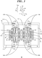
- FIG. 3 shows in a simplified and representative form a top view of a MEMS device 80 in accordance with another embodiment.
- MEMS device 80 is in the form of an accelerometer and is adapted to sense an acceleration force, and in particular X-axis acceleration, Ax, represented by an arrow 82, that is parallel to X-axis 64.
- MEMS device 80 will be referred to hereinafter as X-axis accelerometer 80.
- X-axis accelerometer 80 Of course, it should be readily apparent that by rotating X-axis accelerometer 80 by ninety degrees, it would be equivalently capable of sensing a Y-axis acceleration force parallel to Y-axis 66.
- X-axis accelerometer 80 includes a substrate 84 having a generally planar surface 86. Pairs of electrode elements 88, 90 are formed on planar surface 86 of substrate 84. A movable mass 92 is positioned in spaced apart relationship above planar surface 86 of substrate 84. Again, electrode elements 88, 90 are shaded by a rightwardly and downwardly hatched pattern for illustrative purposes.
- Movable mass 92 has a first portion 94 and a second portion 96.
- second portion 96 surrounds first portion 94 of movable mass 92.
- electrode elements 88, 90 reside in openings 98 formed in first portion 94 of movable mass 92.
- openings may be formed in second portion 96 of movable mass 92 in which electrode elements 88, 90 reside.
- first portion 94 of movable mass 92 is shaded with a stippled pattern to clearly distinguish it from second portion 96 of movable mass 92. It should be understood, however, that first and second portions 94, 96 of movable mass 92 are formed concurrently of the same material during the same process operations.
- a first spring system 100 interconnects first portion 94 of movable mass 92 with second portion 96 of movable mass 92.
- first spring system 100 includes a plurality of straight beam flexures 102 interconnecting first portion 94 with second portion 96.
- an anchor system 104 is coupled to surface 86 of substrate 84, and a second spring system 106 interconnects first portion 94 of movable mass 92 with anchor system 104.
- anchor system 104 includes two anchors 108 physically coupled with substrate 84 and laterally displaced away from one another in a direction substantially parallel to X-axis 64.
- the physical coupling of anchors 108 to substrate 24 is denoted by an "X" extending through each of anchors 108.
- anchor system 104 and second spring system 106 function to suspend first and second portions 94, 96 of movable mass 92 from surface 86 of substrate 84.
- openings 110 extend through first portion 94 of movable mass 92.
- Anchors 108 of anchor system 104 are positioned at an approximate center of each of openings 110.
- X-axis accelerometer 80 is configured to detect an acceleration force, i.e., X-axis acceleration 82, along X-axis 64 substantially parallel to surface 86 of substrate 84.
- second spring system 106 includes springs 112 also residing in openings 110 that are interconnected between each of anchors 108 and first portion 94 of movable mass 92. Springs 112 enable movable mass 92 to translate in a sense direction substantially parallel to the sense axis, i.e., X-axis 64, in response to X-axis acceleration 82.
- second spring system 106 enables first and second portions 94, 96 of movable mass 92 to move together substantially parallel to X-axis 64 in response to X-axis acceleration 82.
- movable mass 92 changes its position relative to the pairs of sensing electrode elements 88, 90 in response to X-axis acceleration 82.
- This change in position results in a set of capacitances whose difference, i.e., a differential capacitance, is indicative of the magnitude of X-axis acceleration 82.
- both portions 94, 96 of movable mass 92 translate together substantially parallel to X-axis 64.
- second portion 96 is able to move. That is, second portion 96 is provided with additional flexibility via the use of flexures 102 of first spring system 100.
- second portion 96 can translate in a direction substantially parallel to Y-axis 66 in response to the undesired shock event 70 and potentially translate into contact with motion limiting structures 114.
- motion limiting structures 114 are coupled to surface 86 of substrate 84 and are laterally displaced away from an outer perimeter 116 of second portion 96 of movable mass 92.
- flexures 102 are generally rigid or resistant to flexing in the sense direction parallel to X-axis 64. Accordingly, the separation of movable mass 92 into first and second portions 94, 96 with first spring system 100 interconnecting them inhibits translational movement of first portion 94 of movable mass 92 in a direction substantially parallel to Y-axis 66 in response to shock event 70. As such, first portion 94 of movable mass 92 is largely limited to purely translational motion in the sense direction substantially parallel to X-axis 64. Therefore, anchor system 104 and second spring system 106 are not subject to the potentially damaging effects of high-g loading from shock event 70.
- X-axis accelerometer 80 The components of X-axis accelerometer 80 are shown in a highly simplified form. Those skilled in the art will recognize that movable mass 92 may have a different shape then at that shown. Additionally, flexures 102 and/or springs 112 may have great variety of shapes, e.g., serpentine configurations, and the like.
- An embodiment of a MEMS device comprises a substrate, a movable mass suspended from the substrate, the movable mass having a first portion and a second portion, and a spring system interconnecting the first portion of the movable mass with the second portion of the movable mass, the spring system enabling movement of the second portion of the movable mass in response to a first force imposed upon the movable mass in a first direction that is orthogonal to a sense direction, wherein the spring system inhibits movement of the first portion of the movable mass in the first direction in response to the first force.
- a MEMS device comprises a substrate, a movable mass suspended from the substrate, the movable mass having a first portion and a second portion, the second portion surrounding the first portion, at least one motion limiting structure laterally displaced away from an outer perimeter of the second portion of the movable mass, and a spring system interconnecting the first portion of the movable mass with the second portion of the movable mass.
- the spring system enables movement of the second portion of the movable mass in response to a first force imposed upon the movable mass in a first direction that is orthogonal to a sense direction, wherein when the second portion of the movable mass moves in the first direction in response to the first force, the second portion of the movable mass contacts the at least one motion limiting structure, and wherein the spring system inhibits movement of the first portion of the movable mass in the first direction in response to the first force.
- a MEMS device comprises a substrate, a movable mass suspended from the substrate, the movable mass having a first portion and a second portion, a first spring system interconnecting the first portion of the movable mass with the second portion of the movable mass, the first spring system including a plurality of spring elements, each of the spring elements enabling motion of the second portion of the movable mass in response to a first force imposed upon the movable mass in a first direction that is orthogonal to a sense direction.
- An anchor system is coupled to the substrate and a second spring system interconnects the first portion of the movable mass with the anchor system to suspend the movable mass from the substrate.
- the second spring system enables the first and second portions of the movable mass to move together in response to a second force imposed upon the movable mass in the sense direction, wherein each of the spring elements of the first spring system are rigid in the sense direction such that the first spring system inhibits movement of the first portion of the movable mass in the first direction in response to the first force.
- Embodiments described herein can yield MEMS devices, and in particular single-axis MEMS accelerometer devices, with improved robustness to off-axis shock events.
- a movable mass configuration that includes a first portion and a second portion interconnected by a first spring system, where the first portion is limited to movement only in a single direction and the second portion is provided with additional flexibility in an off-axis direction via the interconnecting first spring system can increase the suspension robustness of a single axis MEMS sensor device while not disrupting the desired performance of the device. That is, by limiting motion of the first portion to the sensing direction, the transducer suspension spring and anchoring system can be protected from off-axis high acceleration force (i.e., high-g) shock events.
- off-axis high acceleration force i.e., high-g
Landscapes
- Physics & Mathematics (AREA)
- General Physics & Mathematics (AREA)
- Health & Medical Sciences (AREA)
- General Health & Medical Sciences (AREA)
- Toxicology (AREA)
- Engineering & Computer Science (AREA)
- Computer Hardware Design (AREA)
- Microelectronics & Electronic Packaging (AREA)
- Pressure Sensors (AREA)
- Micromachines (AREA)
Abstract
Description
- The present invention relates generally to microelectromechanical systems (MEMS) sensors. More specifically, the present invention relates to a MEMS device, such as a sensor, with protection from off-axis shock events.
- Microelectromechanical Systems (MEMS) sensors are widely used in applications such as automotive, inertial guidance systems, household appliances, protection systems for a variety of devices, and many other industrial, scientific, and engineering systems. Such MEMS sensors are used to sense a physical condition such as acceleration, pressure, angular rotation, or temperature, and to provide an electrical signal representative of the sensed physical condition.
- Capacitive MEMS accelerometers typically include a movable mass that is suspended from a substrate. The movable mass moves, i.e., rotates or translates depending upon the design and sensing direction, in response to an acceleration force. Motion of the movable mass results in a change in electrical capacitance, with respect to the acceleration force, to vary the output of an energized circuit. MEMS accelerometers are often subject to high acceleration forces, referred to herein as shock events, in off-axis directions. Unfortunately, the spring suspension designs used to suspend a movable mass may not be robust to such shock events leading to device failure.
- The accompanying figures in which like reference numerals refer to identical or functionally similar elements throughout the separate views, the figures are not necessarily drawn to scale, and which together with the detailed description below are incorporated in and form part of the specification, serve to further illustrate various embodiments and to explain various principles and advantages all in accordance with the present invention.
-
FIG. 1 shows in a simplified and representative form a top view of a microelectromechanical systems (MEMS) device in accordance with an embodiment; -
FIG. 2 shows a side view of the MEMS device along section lines 2-2 ofFIG. 1 ; and -
FIG. 3 shows in a simplified and representative form a top view of a MEMS device in accordance with another embodiment. - In overview, the present disclosure concerns microelectromechanical systems (MEMS) devices with improved robustness to off-axis acceleration forces, referred to herein as shock events. These MEMS devices can include inertial sensors such as MEMS accelerometers, and in particular, single-axis MEMS accelerometers that sense acceleration along a single axis (e.g., X-direction, Y-direction, or Z-direction). More particularly, a MEMS device includes a movable mass configuration, sometimes called a proof mass, that includes a first portion and a second portion interconnected by a first spring system. The first portion of the movable mass is directly connected to a second spring system that suspends the movable mass from a substrate. The first portion is limited to movement only in a single degree-of-freedom sensing direction. The second portion of the movable mass is provided with additional flexibility in an off-axis direction via the first spring system such that it can potentially move into motion limiting structures in the off-axis direction in response to shock events. This movable mass configuration can increase the suspension robustness of a single axis MEMS sensor device while not disrupting the desired performance of the device. That is, by limiting motion of the first portion to the sensing direction, the transducer suspension spring and anchoring system can be protected from off-axis high acceleration force (i.e., high-g) shock events.
- The instant disclosure is provided to further explain in an enabling fashion the best modes, at the time of the application, of making and using various embodiments in accordance with the present invention. The disclosure is further offered to enhance an understanding and appreciation for the inventive principles and advantages thereof, rather than to limit in any manner the invention. The invention is defined solely by the appended claims including any amendments made during the pendency of this application and all equivalents of those claims as issued.
- It should be understood that the use of relational terms, if any, such as first and second, top and bottom, and the like are used solely to distinguish one from another entity or action without necessarily requiring or implying any actual such relationship or order between such entities or actions. Furthermore, some of the figures may be illustrated using various shading and/or hatching to distinguish the different elements produced within the various structural layers. These different elements within the structural layers may be produced utilizing current and upcoming microfabrication techniques of depositing, patterning, etching, and so forth. Accordingly, although different shading and/or hatching is utilized in the illustrations, the different elements within the structural layers may be formed out of the same material.
- Referring to
FIGs. 1 and 2, FIG. 1 shows in a simplified and representative form a top view of a microelectromechanical systems (MEMS)device 20 in accordance with an embodiment, andFIG. 2 shows a side view of theMEMS device 20 along section lines 2-2 ofFIG. 1 .MEMS device 20 is in the form of an accelerometer and is constructed as a "teeter-totter" type sensor. As such,MEMS device 20 is adapted to sense acceleration, and in particular Z-axis acceleration, Az, represented by anarrow 22 inFIG. 2 .MEMS device 20 will be referred to hereinafter as Z-axis accelerometer 20. - Z-
axis accelerometer 20 includes asubstrate 24 having a generallyplanar surface 26.Electrode elements planar surface 26 ofsubstrate 24. Amovable mass 32, sometimes referred to as a proof mass, is positioned in spaced apart relationship aboveplanar surface 26 ofsubstrate 24. It should be observed thatelectrode elements FIG. 1 by the overlyingmovable mass 32. As such,electrode elements FIG. 1 by dashed line boxes. InFIG. 2 ,electrode elements -
Movable mass 32 has afirst portion 34 and asecond portion 36. In the illustrated example,second portion 36 surroundsfirst portion 34 ofmovable mass 32, andelectrode elements second portion 36 ofmovable mass 32. However, in other embodiments,first portion 34 ofmovable mass 32 may be larger such thatelectrode elements second portions first portion 34 of movable mass.First portion 34 ofmovable mass 32 is shaded with a stippled pattern to clearly distinguish it fromsecond portion 36 ofmovable mass 32. It should be understood, however, that first andsecond portions movable mass 32 are formed concurrently of the same material during the same process operations. - A
first spring system 38 interconnectsfirst portion 34 ofmovable mass 32 withsecond portion 36 of movable mass. In a particular example,first spring system 38 includes a plurality ofstraight beam flexures 40 interconnectingfirst portion 34 withsecond portion 36. Additionally, ananchor system 42 is coupled tosurface 26 ofsubstrate 24, and asecond spring system 44 interconnectsfirst portion 34 ofmovable mass 32 withanchor system 42. In this example,anchor system 42 includes twoanchors 46 physically coupled withsubstrate 24 and astiff beam 48 interconnected to each of the twoanchors 46 and suspended above surface ofsubstrate 24. The physical coupling ofanchors 46 tosubstrate 24 is denoted by an "X" extending through each ofanchors 46. Together,anchor system 42 andsecond spring system 44 function to suspend first andsecond portions movable mass 32 fromsurface 26 ofsubstrate 24 so that an airgap exists betweenmovable mass 32 andelectrode elements 28, 30 (best seen inFIG. 2 ). The components of Z-axis accelerometer 20 may be formed using existing and upcoming MEMS fabrication design rules and processes that include, for example, deposition, patterning, and etching. - As shown, an
opening 50 extends throughmovable mass 32.Anchor system 42 is positioned at an approximate center of opening 50 along an axis ofrotation 52 ofmovable mass 32 between afirst end 54 and asecond end 56 ofmovable mass 32. When intended for operation as a teeter-totter type accelerometer, afirst section 58 ofmovable mass 32 on one side of axis ofrotation 52 is formed with relatively greater mass than asecond section 60 ofmovable mass 32 on the other side of axis ofrotation 52. In an example embodiment, the greater mass offirst section 58 may be created by offsetting axis ofrotation 52 such thatfirst section 58 is longer thansecond section 60. In alternative embodiments, this difference in mass may be accomplished by adding mass tofirst section 58 through an additional layer of material, by removing mass fromsecond section 60 relative tofirst section 58, and so forth. - As mentioned above, Z-
axis accelerometer 20 is configured to detect an acceleration force, i.e., Z-axis acceleration 22, along a Z-axis 62 perpendicular tosurface 26 ofsubstrate 24 in a three dimensional coordinate system that further includes anX-axis 64 and a Y-axis 66. In this example,X-axis 64 and a Y-axis 66 are substantially parallel tosurface 26 ofsubstrate 24. Thus, by convention,X-axis 64 is directed rightward and leftward on the page, Y-axis 66 is directed upward and downward on the page, and Z-axis 62 is directed out of the page inFIG. 1 . Correspondingly, in the side view illustration ofFIG. 2 , the three dimensional coordinate system is represented in whichX-axis 64 is directed rightward and leftward on the page, Z-axis 62 is directed upward and downward on the page, and Y-axis 66 is directed out of the page. - Accordingly,
second spring system 44 includestorsion springs 68 that enablemovable mass 32 to rotate about axis of rotation 52 (where axis ofrotation 52 is substantially parallel to Y-axis 62) in response to Z-axis acceleration 22. In particular, due to their interconnection viaflexures 40 offirst spring system 38,second spring system 44 enables first andsecond portions movable mass 32 to move together about axis ofrotation 52 in response to Z-axis acceleration 22. Thus,movable mass 32 changes its position relative to the underlyingsensing electrode elements axis acceleration 22. This change in position results in a set of capacitances whose difference, i.e., a differential capacitance, is indicative of the magnitude of Z-axis acceleration 22. - In single axis accelerometers, a typical object of design is to produce an accelerometer design such that the resulting behavior closely matches a single-degree-of-freedom system. Such a design constraint calls for a spring suspension design (e.g.,
anchor system 42 with second spring system 44) having high stiffness in the off-axis direction. Although such spring suspension designs may be good at matching the desired ideal behavior, they may not be robust, i.e., resistant to, high acceleration shock events in off-axis directions. InFIG. 1 , such an undesired shock acceleration, referred to herein as a shock event, ASH, 70 is represented by an arrow that is substantially parallel to Y-axis 66. In this undesired direction, torsion springs 68 may be very stiff which results in substantial loading atanchors 46,stiff beam 48, or other features ofanchor system 42 andsecond spring system 44. - In order to enhance the suspension robustness,
movable mass 32 is separated into first andsecond portions axis acceleration 22, bothportions rotation 52. However, in response toshock event 70, onlysecond portion 36 is able to move a significant amount. That is,second portion 36 is provided with additional flexibility via the use offlexures 40 offirst spring system 38. Thus,second portion 36 can translate in a direction substantially parallel to Y-axis 66 in response to theundesired shock event 70. By incorporating this design feature,second portion 36 ofmovable mass 32 can translate into contact with a rigid-stop ormotion limiting structures 72. In this example,motion limiting structures 72 coupled to surface 26 ofsubstrate 24 are laterally displaced away from anouter perimeter 74 ofsecond portion 36 ofmovable mass 32. - However,
flexures 40 are generally rigid or resistant to flexing in the sense direction parallel to Z-axis 62. Accordingly, the separation ofmovable mass 32 into first andsecond portions first spring system 38 interconnecting them inhibits translational movement offirst portion 34 ofmovable mass 32 in a direction substantially parallel to Y-axis 66 in response toshock event 70. As such,first portion 34 ofmovable mass 32 is largely limited to purely rotational motion about axis ofrotation 52. Therefore,anchor system 42 andsecond spring system 44 are not subject to the potentially damaging effects of high-g loading fromshock event 70. - The components of Z-
axis accelerometer 20 are shown in a highly simplified form. Those skilled in the art will recognize thatmovable mass 32 may have a different shape then at that shown. Additionally,flexures 40 and/or torsion springs 68 may have different shapes, e.g., serpentine configurations, and the like. Further, althoughanchor system 42 andsecond spring system 44 are shown as being connected to an interior ofmovable mass 32, it should be understood that reversed configuration is equivalently applicable. For example, a first portion of a movable mass that is coupled to a substrate via a spring suspension system may surround a second portion of a movable mass, where the second portion is able to move in response to a shock event and the first portion is largely limited to pure single axis sense motion. Still further, a suitable spring system may interconnect a first portion and a second portion of a movable mass in which the second portion may be enabled to translate in two directions substantially parallel to the surface of the substrate in response to shock events in two off-axis directions, whereas the first portion of the movable mass interconnected with a spring suspension system is limited to pure single axis sense motion. -
FIG. 3 shows in a simplified and representative form a top view of aMEMS device 80 in accordance with another embodiment.MEMS device 80 is in the form of an accelerometer and is adapted to sense an acceleration force, and in particular X-axis acceleration, Ax, represented by anarrow 82, that is parallel toX-axis 64.MEMS device 80 will be referred to hereinafter asX-axis accelerometer 80. Of course, it should be readily apparent that by rotatingX-axis accelerometer 80 by ninety degrees, it would be equivalently capable of sensing a Y-axis acceleration force parallel to Y-axis 66. -
X-axis accelerometer 80 includes asubstrate 84 having a generallyplanar surface 86. Pairs ofelectrode elements planar surface 86 ofsubstrate 84. Amovable mass 92 is positioned in spaced apart relationship aboveplanar surface 86 ofsubstrate 84. Again,electrode elements -
Movable mass 92 has afirst portion 94 and asecond portion 96. In the illustrated example,second portion 96 surroundsfirst portion 94 ofmovable mass 92. In contrast to Z-axis accelerometer 20 (FIG. 1 ),electrode elements openings 98 formed infirst portion 94 ofmovable mass 92. However, in other embodiments, openings may be formed insecond portion 96 ofmovable mass 92 in which electrodeelements first portion 94 ofmovable mass 92 is shaded with a stippled pattern to clearly distinguish it fromsecond portion 96 ofmovable mass 92. It should be understood, however, that first andsecond portions movable mass 92 are formed concurrently of the same material during the same process operations. - A
first spring system 100 interconnectsfirst portion 94 ofmovable mass 92 withsecond portion 96 ofmovable mass 92. In a particular example,first spring system 100 includes a plurality ofstraight beam flexures 102 interconnectingfirst portion 94 withsecond portion 96. Additionally, ananchor system 104 is coupled to surface 86 ofsubstrate 84, and asecond spring system 106 interconnectsfirst portion 94 ofmovable mass 92 withanchor system 104. In this example,anchor system 104 includes twoanchors 108 physically coupled withsubstrate 84 and laterally displaced away from one another in a direction substantially parallel toX-axis 64. The physical coupling ofanchors 108 tosubstrate 24 is denoted by an "X" extending through each of anchors 108. Together,anchor system 104 andsecond spring system 106 function to suspend first andsecond portions movable mass 92 fromsurface 86 ofsubstrate 84. - As shown,
openings 110 extend throughfirst portion 94 ofmovable mass 92.Anchors 108 ofanchor system 104 are positioned at an approximate center of each ofopenings 110. As mentioned above,X-axis accelerometer 80 is configured to detect an acceleration force, i.e.,X-axis acceleration 82, alongX-axis 64 substantially parallel to surface 86 ofsubstrate 84. Accordingly,second spring system 106 includessprings 112 also residing inopenings 110 that are interconnected between each ofanchors 108 andfirst portion 94 ofmovable mass 92.Springs 112 enablemovable mass 92 to translate in a sense direction substantially parallel to the sense axis, i.e.,X-axis 64, in response toX-axis acceleration 82. In particular, due to their interconnection viaflexures 102 offirst spring system 100,second spring system 106 enables first andsecond portions movable mass 92 to move together substantially parallel to X-axis 64 in response toX-axis acceleration 82. Thus,movable mass 92 changes its position relative to the pairs of sensingelectrode elements X-axis acceleration 82. This change in position results in a set of capacitances whose difference, i.e., a differential capacitance, is indicative of the magnitude ofX-axis acceleration 82. - Under
X-axis acceleration 82, bothportions movable mass 92 translate together substantially parallel toX-axis 64. However, in response to shock event 70 (substantially parallel to Y-axis 66), onlysecond portion 96 is able to move. That is,second portion 96 is provided with additional flexibility via the use offlexures 102 offirst spring system 100. Thus,second portion 96 can translate in a direction substantially parallel to Y-axis 66 in response to theundesired shock event 70 and potentially translate into contact withmotion limiting structures 114. In this example,motion limiting structures 114 are coupled to surface 86 ofsubstrate 84 and are laterally displaced away from anouter perimeter 116 ofsecond portion 96 ofmovable mass 92. - However,
flexures 102 are generally rigid or resistant to flexing in the sense direction parallel toX-axis 64. Accordingly, the separation ofmovable mass 92 into first andsecond portions first spring system 100 interconnecting them inhibits translational movement offirst portion 94 ofmovable mass 92 in a direction substantially parallel to Y-axis 66 in response toshock event 70. As such,first portion 94 ofmovable mass 92 is largely limited to purely translational motion in the sense direction substantially parallel toX-axis 64. Therefore,anchor system 104 andsecond spring system 106 are not subject to the potentially damaging effects of high-g loading fromshock event 70. - The components of
X-axis accelerometer 80 are shown in a highly simplified form. Those skilled in the art will recognize thatmovable mass 92 may have a different shape then at that shown. Additionally,flexures 102 and/or springs 112 may have great variety of shapes, e.g., serpentine configurations, and the like. - In summary, MEMS devices with improved robustness to high-g shock events are discloses. An embodiment of a MEMS device comprises a substrate, a movable mass suspended from the substrate, the movable mass having a first portion and a second portion, and a spring system interconnecting the first portion of the movable mass with the second portion of the movable mass, the spring system enabling movement of the second portion of the movable mass in response to a first force imposed upon the movable mass in a first direction that is orthogonal to a sense direction, wherein the spring system inhibits movement of the first portion of the movable mass in the first direction in response to the first force.
- Another embodiment of a MEMS device comprises a substrate, a movable mass suspended from the substrate, the movable mass having a first portion and a second portion, the second portion surrounding the first portion, at least one motion limiting structure laterally displaced away from an outer perimeter of the second portion of the movable mass, and a spring system interconnecting the first portion of the movable mass with the second portion of the movable mass. The spring system enables movement of the second portion of the movable mass in response to a first force imposed upon the movable mass in a first direction that is orthogonal to a sense direction, wherein when the second portion of the movable mass moves in the first direction in response to the first force, the second portion of the movable mass contacts the at least one motion limiting structure, and wherein the spring system inhibits movement of the first portion of the movable mass in the first direction in response to the first force.
- Yet another embodiment of a MEMS device comprises a substrate, a movable mass suspended from the substrate, the movable mass having a first portion and a second portion, a first spring system interconnecting the first portion of the movable mass with the second portion of the movable mass, the first spring system including a plurality of spring elements, each of the spring elements enabling motion of the second portion of the movable mass in response to a first force imposed upon the movable mass in a first direction that is orthogonal to a sense direction. An anchor system is coupled to the substrate and a second spring system interconnects the first portion of the movable mass with the anchor system to suspend the movable mass from the substrate. The second spring system enables the first and second portions of the movable mass to move together in response to a second force imposed upon the movable mass in the sense direction, wherein each of the spring elements of the first spring system are rigid in the sense direction such that the first spring system inhibits movement of the first portion of the movable mass in the first direction in response to the first force.
- Embodiments described herein can yield MEMS devices, and in particular single-axis MEMS accelerometer devices, with improved robustness to off-axis shock events. A movable mass configuration that includes a first portion and a second portion interconnected by a first spring system, where the first portion is limited to movement only in a single direction and the second portion is provided with additional flexibility in an off-axis direction via the interconnecting first spring system can increase the suspension robustness of a single axis MEMS sensor device while not disrupting the desired performance of the device. That is, by limiting motion of the first portion to the sensing direction, the transducer suspension spring and anchoring system can be protected from off-axis high acceleration force (i.e., high-g) shock events.
- This disclosure is intended to explain how to fashion and use various embodiments in accordance with the invention rather than to limit the true, intended, and fair scope and spirit thereof. The foregoing description is not intended to be exhaustive or to limit the invention to the precise form disclosed. Modifications or variations are possible in light of the above teachings. The embodiment(s) was chosen and described to provide the best illustration of the principles of the invention and its practical application, and to enable one of ordinary skill in the art to utilize the invention in various embodiments and with various modifications as are suited to the particular use contemplated. All such modifications and variations are within the scope of the invention as determined by the appended claims, as may be amended during the pendency of this application for patent, and all equivalents thereof, when interpreted in accordance with the breadth to which they are fairly, legally, and equitably entitled.
Claims (14)
- A microelectromechanical systems (MEMS) device, comprising:a substrate (24, 84);a movable mass (32, 92) suspended from said substrate (24, 84), said movable mass (32, 92) having a first portion (34, 94) and a second portion (36, 96); anda spring system (38, 100) interconnecting said first portion (34, 94) of said movable mass (32, 92) with said second portion (36, 96) of said movable mass (32, 92), said spring system (38, 100) enabling movement of said second portion (36, 96) of said movable mass (32, 92) in response to a first force (70) imposed upon said movable mass (32, 92) in a first direction (66) that is orthogonal to a sense direction (62, 64), wherein said spring system (38, 100) inhibits movement of said first portion (34, 94) of said movable mass (32, 92) in said first direction (66) in response to said first force (70).
- The MEMS device of claim 1, wherein said second portion (36, 96) of said movable mass (32, 92) surrounds said first portion (34, 94) of said movable mass (32, 92).
- The MEMS device of claim 1 or claim 2, further comprising at least one motion limiting structure (72, 114) laterally displaced away from an outer perimeter (74, 116) of said second portion (36, 96) of said movable mass (32, 92) in said first direction (66), wherein when said second portion (36, 96) of said movable mass (32, 92) moves in said first direction (66) in response to said first force (70), said second portion (36, 96) of said movable mass (32, 92) contacts said at least one motion limiting structure (72, 114).
- The MEMS device of any preceding claim, wherein said movement of said second portion (36, 96) of said movable mass (32, 92) in response to said first force (70) is substantially parallel to a surface (26, 86) of said substrate (24, 84).
- The MEMS device of any preceding claim, wherein said spring system (38, 100) comprises a plurality of spring elements, each of said spring elements enabling motion of said second portion (36, 96) of said movable mass (32, 92) in said first direction (66) and said each of said spring elements being rigid in said sense direction (62, 64).
- The MEMS device of any preceding claim, wherein said spring system (38, 100) comprises a plurality of straight beam flexures (40, 102) interconnecting said first portion (34, 94) of said movable mass (32, 92) with said second portion (36, 96) of said movable mass (32, 92)
- The MEMS device of any preceding claim, wherein said spring system (38, 100) is a first spring system, and said MEMS device further comprises:an anchor system (42, 104) coupled to said substrate (24, 84); anda second spring system (44, 106) interconnecting said first portion (34, 94) of said movable mass (32, 92) with said anchor system (42, 104), said second spring system (44, 106) enabling said first and second portions (34, 94; 36, 96) of said movable mass (32, 92) to move together in response to a second force (22, 82) imposed upon said movable mass (32, 92) in said sense direction (62, 64).
- The MEMS device of claim 7 wherein said first spring system (38, 100) isolates said anchor system (42, 104) and said second spring system (44, 106) from movement in said first direction (66) in response to said first force (70).
- The MEMS device of claim 7 or claim 8, wherein said sense direction (62, 64) is substantially perpendicular to a surface (26, 86) of said substrate (24, 84), and said second spring system (44, 106) comprises a torsion spring (68) for enabling of said first and second portions (34, 94; 36, 96) of said movable mass (32, 92) about a rotational axis that is substantially parallel to said surface (26, 86) of said substrate (24, 84) in response to said second force (22, 82) imposed upon said movable mass (32, 92) in said sense direction (62, 64).
- The MEMS device of claim 9, further comprising sense electrodes (28, 30, 88, 90) formed on said surface (26, 86) of said substrate (24, 84) and underlying said second portion (36, 96) of said movable mass (32, 92).
- The MEMS device of any one of the claims 7 to 10, wherein said sense direction (62, 64) is substantially parallel to a surface (26, 86) of said substrate (24, 84), and said second spring system (44, 106) comprises spring elements for enabling translational motion of said first and second portions (34, 94; 36, 96) of said movable mass (32, 92) in response to said second force (22, 82) imposed upon said movable mass (32, 92) in said sense direction (62, 64).
- The MEMS device of claim 11, wherein:said first portion (34, 94) of said movable mass (32, 92) includes a plurality of movable electrodes; andsaid MEMS device further comprises fixed electrodes (28, 30, 88, 90) formed on said substrate (24, 84) in proximity to said movable electrodes of said first portion (34, 94) of said movable mass (32, 92).
- The MEMS device of any preceding claim,
wherein said spring system (38, 100) including a plurality of spring elements
wherein said each of said spring elements of said spring system (38, 100) are rigid in said sense direction (62, 64). - The MEMS device of any preceding claim, wherein said MEMS device further comprises fixed electrodes (28, 30, 88, 90) formed on said substrate (24, 84) in proximity to said movable electrodes of said first portion (34, 94) of said movable mass (32, 92).
Applications Claiming Priority (1)
| Application Number | Priority Date | Filing Date | Title |
|---|---|---|---|
| US15/432,133 US10247753B2 (en) | 2017-02-14 | 2017-02-14 | MEMS device with off-axis shock protection |
Publications (2)
| Publication Number | Publication Date |
|---|---|
| EP3361265A1 true EP3361265A1 (en) | 2018-08-15 |
| EP3361265B1 EP3361265B1 (en) | 2019-08-28 |
Family
ID=60990661
Family Applications (1)
| Application Number | Title | Priority Date | Filing Date |
|---|---|---|---|
| EP18151249.2A Active EP3361265B1 (en) | 2017-02-14 | 2018-01-11 | Mems device with off-axis shock protection |
Country Status (3)
| Country | Link |
|---|---|
| US (1) | US10247753B2 (en) |
| EP (1) | EP3361265B1 (en) |
| CN (1) | CN108423633B (en) |
Families Citing this family (7)
| Publication number | Priority date | Publication date | Assignee | Title |
|---|---|---|---|---|
| JP2020030067A (en) * | 2018-08-21 | 2020-02-27 | セイコーエプソン株式会社 | Physical quantity sensor, sensor device, electronic device, and movable body |
| FR3094708B1 (en) * | 2019-04-08 | 2022-12-02 | Commissariat Energie Atomique | OFF-PLANE HINGE FOR MICROMECHANICAL AND/OR NANOMECHANICAL STRUCTURE WITH REDUCED SENSITIVITY TO INTERNAL STRESS |
| US11415595B2 (en) * | 2019-06-28 | 2022-08-16 | Analog Devices, Inc. | Multiple anchor high frequency accelerometer |
| US20220050124A1 (en) * | 2020-08-17 | 2022-02-17 | Nxp Usa, Inc. | Inertial sensor with split anchors and flexure compliance between the anchors |
| CN112247920B (en) * | 2020-11-11 | 2025-06-27 | 广东工业大学 | A single-degree-of-freedom positioning platform with large travel |
| EP4187258A1 (en) * | 2021-11-25 | 2023-05-31 | STMicroelectronics S.r.l. | Z-axis microelectromechanical sensor device with improved stress insensitivity |
| WO2025184720A1 (en) * | 2024-03-04 | 2025-09-12 | Sheba Microsystems Inc. | Drop resistant mems actuator-imager assembly package |
Citations (3)
| Publication number | Priority date | Publication date | Assignee | Title |
|---|---|---|---|---|
| US20100058864A1 (en) * | 2008-09-05 | 2010-03-11 | Industrial Technology Research Institute | Multi-axis capacitive accelerometer |
| US20140090468A1 (en) * | 2012-03-16 | 2014-04-03 | Advanced Numicro Systems, Inc. | Tri-axial mems inertial sensor |
| US20150309069A1 (en) * | 2012-12-27 | 2015-10-29 | Tronic' S Microsystems | Micro-electromechanical device comprising a mobile mass that can move out-of-plane |
Family Cites Families (36)
| Publication number | Priority date | Publication date | Assignee | Title |
|---|---|---|---|---|
| US5220835A (en) * | 1991-09-12 | 1993-06-22 | Ford Motor Company | Torsion beam accelerometer |
| US5488864A (en) * | 1994-12-19 | 1996-02-06 | Ford Motor Company | Torsion beam accelerometer with slotted tilt plate |
| US6928872B2 (en) * | 2001-04-27 | 2005-08-16 | Stmicroelectronics S.R.L. | Integrated gyroscope of semiconductor material with at least one sensitive axis in the sensor plane |
| US20030209073A1 (en) * | 2002-04-17 | 2003-11-13 | Raymond Carroll | Tuned flexure accelerometer |
| US6865944B2 (en) | 2002-12-16 | 2005-03-15 | Honeywell International Inc. | Methods and systems for decelerating proof mass movements within MEMS structures |
| US7013730B2 (en) | 2003-12-15 | 2006-03-21 | Honeywell International, Inc. | Internally shock caged serpentine flexure for micro-machined accelerometer |
| TWI255341B (en) * | 2004-06-10 | 2006-05-21 | Chung Shan Inst Of Science | Miniature accelerator |
| US20070220973A1 (en) * | 2005-08-12 | 2007-09-27 | Cenk Acar | Multi-axis micromachined accelerometer and rate sensor |
| DE102006048381A1 (en) * | 2006-10-12 | 2008-04-17 | Fraunhofer-Gesellschaft zur Förderung der angewandten Forschung e.V. | Sensor for detecting accelerations |
| EP2246706B1 (en) * | 2008-02-07 | 2013-01-09 | Alps Electric Co., Ltd. | Physical quantity sensor |
| DE102008001442A1 (en) * | 2008-04-29 | 2009-11-05 | Robert Bosch Gmbh | Micromechanical component and method for operating a micromechanical component |
| DE102008040855B4 (en) * | 2008-07-30 | 2022-05-25 | Robert Bosch Gmbh | Triaxial accelerometer |
| JP5029551B2 (en) * | 2008-09-18 | 2012-09-19 | 富士通株式会社 | Micro oscillating device, micro oscillating device array, and optical switching device |
| US8020443B2 (en) * | 2008-10-30 | 2011-09-20 | Freescale Semiconductor, Inc. | Transducer with decoupled sensing in mutually orthogonal directions |
| US8555720B2 (en) * | 2011-02-24 | 2013-10-15 | Freescale Semiconductor, Inc. | MEMS device with enhanced resistance to stiction |
| DE102011076551B4 (en) * | 2011-05-26 | 2024-02-22 | Robert Bosch Gmbh | Inertial sensor |
| US20130042686A1 (en) * | 2011-08-17 | 2013-02-21 | Sitronix Technology Corp. | Inertia sensing apparatus |
| EP2762893B1 (en) * | 2011-09-30 | 2016-06-15 | Microinfinity, Inc. | Mems resonant accelerometer |
| US8978475B2 (en) * | 2012-02-01 | 2015-03-17 | Fairchild Semiconductor Corporation | MEMS proof mass with split z-axis portions |
| JP5880877B2 (en) * | 2012-05-15 | 2016-03-09 | 株式会社デンソー | Sensor device |
| JP6002481B2 (en) * | 2012-07-06 | 2016-10-05 | 日立オートモティブシステムズ株式会社 | Inertial sensor |
| US9335170B2 (en) * | 2012-11-28 | 2016-05-10 | Freescale Semiconductor, Inc. | Inertial sensor and method of levitation effect compensation |
| US20140260613A1 (en) | 2013-03-15 | 2014-09-18 | Invensense, Inc. | Elastic bump stops for mems devices |
| ITTO20130237A1 (en) * | 2013-03-22 | 2014-09-23 | St Microelectronics Srl | HIGH SENSITIVITY MICROELECTROMECHANICAL DETECTION OF Z AXIS, IN PARTICULAR FOR A MEMS ACCELEROMETER |
| US20150268268A1 (en) * | 2013-06-17 | 2015-09-24 | Freescale Semiconductor, Inc. | Inertial sensor with trim capacitance and method of trimming offset |
| US9476712B2 (en) | 2013-07-31 | 2016-10-25 | Honeywell International Inc. | MEMS device mechanism enhancement for robust operation through severe shock and acceleration |
| US9242851B2 (en) * | 2013-08-06 | 2016-01-26 | Freescale Semiconductor, Inc | MEMS device with differential vertical sense electrodes |
| FI125695B (en) * | 2013-09-11 | 2016-01-15 | Murata Manufacturing Co | Improved gyroscope construction and gyroscope |
| DE102013222747A1 (en) * | 2013-11-08 | 2015-05-13 | Robert Bosch Gmbh | Micromechanical Z-sensor |
| US10371715B2 (en) * | 2013-12-23 | 2019-08-06 | Invensense, Inc. | MEMS accelerometer with proof masses moving in an anti-phase direction |
| FI126598B (en) * | 2014-02-26 | 2017-03-15 | Murata Manufacturing Co | Microelectromechanical device with motion limiter |
| US10031156B2 (en) * | 2014-09-23 | 2018-07-24 | Nxp Usa, Inc. | Three-axis microelectromechanical systems devices |
| US9360496B2 (en) * | 2014-10-03 | 2016-06-07 | Freescale Semiconductor, Inc. | Three-axis microelectromechanical systems device with single proof mass |
| US9638712B2 (en) * | 2015-01-22 | 2017-05-02 | Nxp Usa, Inc. | MEMS device with over-travel stop structure and method of fabrication |
| US20160370180A1 (en) * | 2015-06-17 | 2016-12-22 | Freescale Semiconductor, Inc. | Inertial sensor with couple spring for common mode rejection |
| US9720012B2 (en) * | 2015-07-21 | 2017-08-01 | Nxp Usa, Inc. | Multi-axis inertial sensor with dual mass and integrated damping structure |
-
2017
- 2017-02-14 US US15/432,133 patent/US10247753B2/en active Active
-
2018
- 2018-01-11 EP EP18151249.2A patent/EP3361265B1/en active Active
- 2018-02-09 CN CN201810139900.2A patent/CN108423633B/en active Active
Patent Citations (3)
| Publication number | Priority date | Publication date | Assignee | Title |
|---|---|---|---|---|
| US20100058864A1 (en) * | 2008-09-05 | 2010-03-11 | Industrial Technology Research Institute | Multi-axis capacitive accelerometer |
| US20140090468A1 (en) * | 2012-03-16 | 2014-04-03 | Advanced Numicro Systems, Inc. | Tri-axial mems inertial sensor |
| US20150309069A1 (en) * | 2012-12-27 | 2015-10-29 | Tronic' S Microsystems | Micro-electromechanical device comprising a mobile mass that can move out-of-plane |
Also Published As
| Publication number | Publication date |
|---|---|
| CN108423633A (en) | 2018-08-21 |
| CN108423633B (en) | 2023-10-24 |
| US10247753B2 (en) | 2019-04-02 |
| US20180231579A1 (en) | 2018-08-16 |
| EP3361265B1 (en) | 2019-08-28 |
Similar Documents
| Publication | Publication Date | Title |
|---|---|---|
| US10247753B2 (en) | MEMS device with off-axis shock protection | |
| CN109696164B (en) | MEMS device with two-stage motion limiting structure | |
| EP3382400B1 (en) | Three-axis inertial sensor for detecting linear acceleration | |
| EP3121605B1 (en) | Multi-axis inertial sensor with dual mass and integrated damping structure | |
| JP5214984B2 (en) | Z-axis microelectromechanical device with improved stopper structure | |
| EP3499244B1 (en) | Single axis inertial sensor with suppressed parasitic modes | |
| US9346670B2 (en) | MEMS device with differential vertical sense electrodes | |
| EP3717400B1 (en) | Asymmetric out-of-plane accelerometer | |
| US20140144232A1 (en) | Spring for microelectromechanical systems (mems) device | |
| EP3151018B1 (en) | Mems sensor with reduced cross-axis sensitivity | |
| US9476711B2 (en) | Angular rate sensor with quadrature error compensation | |
| EP3564682B1 (en) | Inertial sensor with single proof mass and multiple sense axis capability | |
| US11105826B2 (en) | Inertial sensor with integrated damping structures | |
| CN113148943A (en) | Sensor device and manufacturing method | |
| US20220050124A1 (en) | Inertial sensor with split anchors and flexure compliance between the anchors | |
| CN109073673A (en) | Micro mechanical sensor and method for manufacturing micro mechanical sensor |
Legal Events
| Date | Code | Title | Description |
|---|---|---|---|
| PUAI | Public reference made under article 153(3) epc to a published international application that has entered the european phase |
Free format text: ORIGINAL CODE: 0009012 |
|
| STAA | Information on the status of an ep patent application or granted ep patent |
Free format text: STATUS: THE APPLICATION HAS BEEN PUBLISHED |
|
| AK | Designated contracting states |
Kind code of ref document: A1 Designated state(s): AL AT BE BG CH CY CZ DE DK EE ES FI FR GB GR HR HU IE IS IT LI LT LU LV MC MK MT NL NO PL PT RO RS SE SI SK SM TR |
|
| AX | Request for extension of the european patent |
Extension state: BA ME |
|
| STAA | Information on the status of an ep patent application or granted ep patent |
Free format text: STATUS: REQUEST FOR EXAMINATION WAS MADE |
|
| 17P | Request for examination filed |
Effective date: 20190215 |
|
| RBV | Designated contracting states (corrected) |
Designated state(s): AL AT BE BG CH CY CZ DE DK EE ES FI FR GB GR HR HU IE IS IT LI LT LU LV MC MK MT NL NO PL PT RO RS SE SI SK SM TR |
|
| GRAP | Despatch of communication of intention to grant a patent |
Free format text: ORIGINAL CODE: EPIDOSNIGR1 |
|
| STAA | Information on the status of an ep patent application or granted ep patent |
Free format text: STATUS: GRANT OF PATENT IS INTENDED |
|
| INTG | Intention to grant announced |
Effective date: 20190411 |
|
| GRAJ | Information related to disapproval of communication of intention to grant by the applicant or resumption of examination proceedings by the epo deleted |
Free format text: ORIGINAL CODE: EPIDOSDIGR1 |
|
| STAA | Information on the status of an ep patent application or granted ep patent |
Free format text: STATUS: REQUEST FOR EXAMINATION WAS MADE |
|
| GRAP | Despatch of communication of intention to grant a patent |
Free format text: ORIGINAL CODE: EPIDOSNIGR1 |
|
| STAA | Information on the status of an ep patent application or granted ep patent |
Free format text: STATUS: GRANT OF PATENT IS INTENDED |
|
| INTC | Intention to grant announced (deleted) | ||
| GRAS | Grant fee paid |
Free format text: ORIGINAL CODE: EPIDOSNIGR3 |
|
| GRAA | (expected) grant |
Free format text: ORIGINAL CODE: 0009210 |
|
| STAA | Information on the status of an ep patent application or granted ep patent |
Free format text: STATUS: THE PATENT HAS BEEN GRANTED |
|
| INTG | Intention to grant announced |
Effective date: 20190701 |
|
| AK | Designated contracting states |
Kind code of ref document: B1 Designated state(s): AL AT BE BG CH CY CZ DE DK EE ES FI FR GB GR HR HU IE IS IT LI LT LU LV MC MK MT NL NO PL PT RO RS SE SI SK SM TR |
|
| REG | Reference to a national code |
Ref country code: GB Ref legal event code: FG4D |
|
| REG | Reference to a national code |
Ref country code: CH Ref legal event code: EP |
|
| REG | Reference to a national code |
Ref country code: AT Ref legal event code: REF Ref document number: 1173051 Country of ref document: AT Kind code of ref document: T Effective date: 20190915 |
|
| REG | Reference to a national code |
Ref country code: IE Ref legal event code: FG4D |
|
| REG | Reference to a national code |
Ref country code: DE Ref legal event code: R096 Ref document number: 602018000466 Country of ref document: DE |
|
| REG | Reference to a national code |
Ref country code: NL Ref legal event code: MP Effective date: 20190828 |
|
| REG | Reference to a national code |
Ref country code: LT Ref legal event code: MG4D |
|
| PG25 | Lapsed in a contracting state [announced via postgrant information from national office to epo] |
Ref country code: NO Free format text: LAPSE BECAUSE OF FAILURE TO SUBMIT A TRANSLATION OF THE DESCRIPTION OR TO PAY THE FEE WITHIN THE PRESCRIBED TIME-LIMIT Effective date: 20191128 Ref country code: LT Free format text: LAPSE BECAUSE OF FAILURE TO SUBMIT A TRANSLATION OF THE DESCRIPTION OR TO PAY THE FEE WITHIN THE PRESCRIBED TIME-LIMIT Effective date: 20190828 Ref country code: BG Free format text: LAPSE BECAUSE OF FAILURE TO SUBMIT A TRANSLATION OF THE DESCRIPTION OR TO PAY THE FEE WITHIN THE PRESCRIBED TIME-LIMIT Effective date: 20191128 Ref country code: NL Free format text: LAPSE BECAUSE OF FAILURE TO SUBMIT A TRANSLATION OF THE DESCRIPTION OR TO PAY THE FEE WITHIN THE PRESCRIBED TIME-LIMIT Effective date: 20190828 Ref country code: FI Free format text: LAPSE BECAUSE OF FAILURE TO SUBMIT A TRANSLATION OF THE DESCRIPTION OR TO PAY THE FEE WITHIN THE PRESCRIBED TIME-LIMIT Effective date: 20190828 Ref country code: PT Free format text: LAPSE BECAUSE OF FAILURE TO SUBMIT A TRANSLATION OF THE DESCRIPTION OR TO PAY THE FEE WITHIN THE PRESCRIBED TIME-LIMIT Effective date: 20191230 Ref country code: HR Free format text: LAPSE BECAUSE OF FAILURE TO SUBMIT A TRANSLATION OF THE DESCRIPTION OR TO PAY THE FEE WITHIN THE PRESCRIBED TIME-LIMIT Effective date: 20190828 Ref country code: SE Free format text: LAPSE BECAUSE OF FAILURE TO SUBMIT A TRANSLATION OF THE DESCRIPTION OR TO PAY THE FEE WITHIN THE PRESCRIBED TIME-LIMIT Effective date: 20190828 |
|
| PG25 | Lapsed in a contracting state [announced via postgrant information from national office to epo] |
Ref country code: ES Free format text: LAPSE BECAUSE OF FAILURE TO SUBMIT A TRANSLATION OF THE DESCRIPTION OR TO PAY THE FEE WITHIN THE PRESCRIBED TIME-LIMIT Effective date: 20190828 Ref country code: GR Free format text: LAPSE BECAUSE OF FAILURE TO SUBMIT A TRANSLATION OF THE DESCRIPTION OR TO PAY THE FEE WITHIN THE PRESCRIBED TIME-LIMIT Effective date: 20191129 Ref country code: AL Free format text: LAPSE BECAUSE OF FAILURE TO SUBMIT A TRANSLATION OF THE DESCRIPTION OR TO PAY THE FEE WITHIN THE PRESCRIBED TIME-LIMIT Effective date: 20190828 Ref country code: IS Free format text: LAPSE BECAUSE OF FAILURE TO SUBMIT A TRANSLATION OF THE DESCRIPTION OR TO PAY THE FEE WITHIN THE PRESCRIBED TIME-LIMIT Effective date: 20191228 Ref country code: RS Free format text: LAPSE BECAUSE OF FAILURE TO SUBMIT A TRANSLATION OF THE DESCRIPTION OR TO PAY THE FEE WITHIN THE PRESCRIBED TIME-LIMIT Effective date: 20190828 Ref country code: LV Free format text: LAPSE BECAUSE OF FAILURE TO SUBMIT A TRANSLATION OF THE DESCRIPTION OR TO PAY THE FEE WITHIN THE PRESCRIBED TIME-LIMIT Effective date: 20190828 |
|
| REG | Reference to a national code |
Ref country code: AT Ref legal event code: MK05 Ref document number: 1173051 Country of ref document: AT Kind code of ref document: T Effective date: 20190828 |
|
| PG25 | Lapsed in a contracting state [announced via postgrant information from national office to epo] |
Ref country code: TR Free format text: LAPSE BECAUSE OF FAILURE TO SUBMIT A TRANSLATION OF THE DESCRIPTION OR TO PAY THE FEE WITHIN THE PRESCRIBED TIME-LIMIT Effective date: 20190828 |
|
| PG25 | Lapsed in a contracting state [announced via postgrant information from national office to epo] |
Ref country code: IT Free format text: LAPSE BECAUSE OF FAILURE TO SUBMIT A TRANSLATION OF THE DESCRIPTION OR TO PAY THE FEE WITHIN THE PRESCRIBED TIME-LIMIT Effective date: 20190828 Ref country code: AT Free format text: LAPSE BECAUSE OF FAILURE TO SUBMIT A TRANSLATION OF THE DESCRIPTION OR TO PAY THE FEE WITHIN THE PRESCRIBED TIME-LIMIT Effective date: 20190828 Ref country code: DK Free format text: LAPSE BECAUSE OF FAILURE TO SUBMIT A TRANSLATION OF THE DESCRIPTION OR TO PAY THE FEE WITHIN THE PRESCRIBED TIME-LIMIT Effective date: 20190828 Ref country code: EE Free format text: LAPSE BECAUSE OF FAILURE TO SUBMIT A TRANSLATION OF THE DESCRIPTION OR TO PAY THE FEE WITHIN THE PRESCRIBED TIME-LIMIT Effective date: 20190828 Ref country code: RO Free format text: LAPSE BECAUSE OF FAILURE TO SUBMIT A TRANSLATION OF THE DESCRIPTION OR TO PAY THE FEE WITHIN THE PRESCRIBED TIME-LIMIT Effective date: 20190828 Ref country code: PL Free format text: LAPSE BECAUSE OF FAILURE TO SUBMIT A TRANSLATION OF THE DESCRIPTION OR TO PAY THE FEE WITHIN THE PRESCRIBED TIME-LIMIT Effective date: 20190828 |
|
| PG25 | Lapsed in a contracting state [announced via postgrant information from national office to epo] |
Ref country code: IS Free format text: LAPSE BECAUSE OF FAILURE TO SUBMIT A TRANSLATION OF THE DESCRIPTION OR TO PAY THE FEE WITHIN THE PRESCRIBED TIME-LIMIT Effective date: 20200224 Ref country code: SK Free format text: LAPSE BECAUSE OF FAILURE TO SUBMIT A TRANSLATION OF THE DESCRIPTION OR TO PAY THE FEE WITHIN THE PRESCRIBED TIME-LIMIT Effective date: 20190828 Ref country code: CZ Free format text: LAPSE BECAUSE OF FAILURE TO SUBMIT A TRANSLATION OF THE DESCRIPTION OR TO PAY THE FEE WITHIN THE PRESCRIBED TIME-LIMIT Effective date: 20190828 Ref country code: SM Free format text: LAPSE BECAUSE OF FAILURE TO SUBMIT A TRANSLATION OF THE DESCRIPTION OR TO PAY THE FEE WITHIN THE PRESCRIBED TIME-LIMIT Effective date: 20190828 |
|
| REG | Reference to a national code |
Ref country code: DE Ref legal event code: R097 Ref document number: 602018000466 Country of ref document: DE |
|
| PLBE | No opposition filed within time limit |
Free format text: ORIGINAL CODE: 0009261 |
|
| STAA | Information on the status of an ep patent application or granted ep patent |
Free format text: STATUS: NO OPPOSITION FILED WITHIN TIME LIMIT |
|
| PG2D | Information on lapse in contracting state deleted |
Ref country code: IS |
|
| 26N | No opposition filed |
Effective date: 20200603 |
|
| PG25 | Lapsed in a contracting state [announced via postgrant information from national office to epo] |
Ref country code: SI Free format text: LAPSE BECAUSE OF FAILURE TO SUBMIT A TRANSLATION OF THE DESCRIPTION OR TO PAY THE FEE WITHIN THE PRESCRIBED TIME-LIMIT Effective date: 20190828 Ref country code: MC Free format text: LAPSE BECAUSE OF FAILURE TO SUBMIT A TRANSLATION OF THE DESCRIPTION OR TO PAY THE FEE WITHIN THE PRESCRIBED TIME-LIMIT Effective date: 20190828 |
|
| REG | Reference to a national code |
Ref country code: BE Ref legal event code: MM Effective date: 20200131 |
|
| PG25 | Lapsed in a contracting state [announced via postgrant information from national office to epo] |
Ref country code: LU Free format text: LAPSE BECAUSE OF NON-PAYMENT OF DUE FEES Effective date: 20200111 |
|
| PG25 | Lapsed in a contracting state [announced via postgrant information from national office to epo] |
Ref country code: BE Free format text: LAPSE BECAUSE OF NON-PAYMENT OF DUE FEES Effective date: 20200131 |
|
| PG25 | Lapsed in a contracting state [announced via postgrant information from national office to epo] |
Ref country code: IE Free format text: LAPSE BECAUSE OF NON-PAYMENT OF DUE FEES Effective date: 20200111 |
|
| REG | Reference to a national code |
Ref country code: CH Ref legal event code: PL |
|
| PG25 | Lapsed in a contracting state [announced via postgrant information from national office to epo] |
Ref country code: CH Free format text: LAPSE BECAUSE OF NON-PAYMENT OF DUE FEES Effective date: 20210131 Ref country code: LI Free format text: LAPSE BECAUSE OF NON-PAYMENT OF DUE FEES Effective date: 20210131 |
|
| PG25 | Lapsed in a contracting state [announced via postgrant information from national office to epo] |
Ref country code: MT Free format text: LAPSE BECAUSE OF FAILURE TO SUBMIT A TRANSLATION OF THE DESCRIPTION OR TO PAY THE FEE WITHIN THE PRESCRIBED TIME-LIMIT Effective date: 20190828 Ref country code: CY Free format text: LAPSE BECAUSE OF FAILURE TO SUBMIT A TRANSLATION OF THE DESCRIPTION OR TO PAY THE FEE WITHIN THE PRESCRIBED TIME-LIMIT Effective date: 20190828 |
|
| PG25 | Lapsed in a contracting state [announced via postgrant information from national office to epo] |
Ref country code: MK Free format text: LAPSE BECAUSE OF FAILURE TO SUBMIT A TRANSLATION OF THE DESCRIPTION OR TO PAY THE FEE WITHIN THE PRESCRIBED TIME-LIMIT Effective date: 20190828 |
|
| P01 | Opt-out of the competence of the unified patent court (upc) registered |
Effective date: 20230725 |
|
| PGFP | Annual fee paid to national office [announced via postgrant information from national office to epo] |
Ref country code: GB Payment date: 20251220 Year of fee payment: 9 |
|
| PGFP | Annual fee paid to national office [announced via postgrant information from national office to epo] |
Ref country code: FR Payment date: 20251217 Year of fee payment: 9 |
|
| REG | Reference to a national code |
Ref country code: GB Ref legal event code: 732E Free format text: REGISTERED BETWEEN 20260312 AND 20260318 |
|
| PGFP | Annual fee paid to national office [announced via postgrant information from national office to epo] |
Ref country code: DE Payment date: 20251217 Year of fee payment: 9 |