EP3360985A1 - Multilayer abradable coating - Google Patents
Multilayer abradable coating Download PDFInfo
- Publication number
- EP3360985A1 EP3360985A1 EP18156006.1A EP18156006A EP3360985A1 EP 3360985 A1 EP3360985 A1 EP 3360985A1 EP 18156006 A EP18156006 A EP 18156006A EP 3360985 A1 EP3360985 A1 EP 3360985A1
- Authority
- EP
- European Patent Office
- Prior art keywords
- abradable
- layer
- coating
- abradable layer
- coated part
- Prior art date
- Legal status (The legal status is an assumption and is not a legal conclusion. Google has not performed a legal analysis and makes no representation as to the accuracy of the status listed.)
- Granted
Links
Images

Classifications
-
- C—CHEMISTRY; METALLURGY
- C23—COATING METALLIC MATERIAL; COATING MATERIAL WITH METALLIC MATERIAL; CHEMICAL SURFACE TREATMENT; DIFFUSION TREATMENT OF METALLIC MATERIAL; COATING BY VACUUM EVAPORATION, BY SPUTTERING, BY ION IMPLANTATION OR BY CHEMICAL VAPOUR DEPOSITION, IN GENERAL; INHIBITING CORROSION OF METALLIC MATERIAL OR INCRUSTATION IN GENERAL
- C23C—COATING METALLIC MATERIAL; COATING MATERIAL WITH METALLIC MATERIAL; SURFACE TREATMENT OF METALLIC MATERIAL BY DIFFUSION INTO THE SURFACE, BY CHEMICAL CONVERSION OR SUBSTITUTION; COATING BY VACUUM EVAPORATION, BY SPUTTERING, BY ION IMPLANTATION OR BY CHEMICAL VAPOUR DEPOSITION, IN GENERAL
- C23C28/00—Coating for obtaining at least two superposed coatings either by methods not provided for in a single one of groups C23C2/00 - C23C26/00 or by combinations of methods provided for in subclasses C23C and C25C or C25D
- C23C28/02—Coating for obtaining at least two superposed coatings either by methods not provided for in a single one of groups C23C2/00 - C23C26/00 or by combinations of methods provided for in subclasses C23C and C25C or C25D only coatings only including layers of metallic material
- C23C28/021—Coating for obtaining at least two superposed coatings either by methods not provided for in a single one of groups C23C2/00 - C23C26/00 or by combinations of methods provided for in subclasses C23C and C25C or C25D only coatings only including layers of metallic material including at least one metal alloy layer
- C23C28/022—Coating for obtaining at least two superposed coatings either by methods not provided for in a single one of groups C23C2/00 - C23C26/00 or by combinations of methods provided for in subclasses C23C and C25C or C25D only coatings only including layers of metallic material including at least one metal alloy layer with at least one MCrAlX layer
-
- F—MECHANICAL ENGINEERING; LIGHTING; HEATING; WEAPONS; BLASTING
- F04—POSITIVE - DISPLACEMENT MACHINES FOR LIQUIDS; PUMPS FOR LIQUIDS OR ELASTIC FLUIDS
- F04D—NON-POSITIVE-DISPLACEMENT PUMPS
- F04D29/00—Details, component parts, or accessories
- F04D29/08—Sealings
- F04D29/16—Sealings between pressure and suction sides
- F04D29/161—Sealings between pressure and suction sides especially adapted for elastic fluid pumps
- F04D29/164—Sealings between pressure and suction sides especially adapted for elastic fluid pumps of an axial flow wheel
-
- C—CHEMISTRY; METALLURGY
- C23—COATING METALLIC MATERIAL; COATING MATERIAL WITH METALLIC MATERIAL; CHEMICAL SURFACE TREATMENT; DIFFUSION TREATMENT OF METALLIC MATERIAL; COATING BY VACUUM EVAPORATION, BY SPUTTERING, BY ION IMPLANTATION OR BY CHEMICAL VAPOUR DEPOSITION, IN GENERAL; INHIBITING CORROSION OF METALLIC MATERIAL OR INCRUSTATION IN GENERAL
- C23C—COATING METALLIC MATERIAL; COATING MATERIAL WITH METALLIC MATERIAL; SURFACE TREATMENT OF METALLIC MATERIAL BY DIFFUSION INTO THE SURFACE, BY CHEMICAL CONVERSION OR SUBSTITUTION; COATING BY VACUUM EVAPORATION, BY SPUTTERING, BY ION IMPLANTATION OR BY CHEMICAL VAPOUR DEPOSITION, IN GENERAL
- C23C24/00—Coating starting from inorganic powder
- C23C24/02—Coating starting from inorganic powder by application of pressure only
- C23C24/04—Impact or kinetic deposition of particles
-
- C—CHEMISTRY; METALLURGY
- C23—COATING METALLIC MATERIAL; COATING MATERIAL WITH METALLIC MATERIAL; CHEMICAL SURFACE TREATMENT; DIFFUSION TREATMENT OF METALLIC MATERIAL; COATING BY VACUUM EVAPORATION, BY SPUTTERING, BY ION IMPLANTATION OR BY CHEMICAL VAPOUR DEPOSITION, IN GENERAL; INHIBITING CORROSION OF METALLIC MATERIAL OR INCRUSTATION IN GENERAL
- C23C—COATING METALLIC MATERIAL; COATING MATERIAL WITH METALLIC MATERIAL; SURFACE TREATMENT OF METALLIC MATERIAL BY DIFFUSION INTO THE SURFACE, BY CHEMICAL CONVERSION OR SUBSTITUTION; COATING BY VACUUM EVAPORATION, BY SPUTTERING, BY ION IMPLANTATION OR BY CHEMICAL VAPOUR DEPOSITION, IN GENERAL
- C23C28/00—Coating for obtaining at least two superposed coatings either by methods not provided for in a single one of groups C23C2/00 - C23C26/00 or by combinations of methods provided for in subclasses C23C and C25C or C25D
- C23C28/02—Coating for obtaining at least two superposed coatings either by methods not provided for in a single one of groups C23C2/00 - C23C26/00 or by combinations of methods provided for in subclasses C23C and C25C or C25D only coatings only including layers of metallic material
- C23C28/027—Coating for obtaining at least two superposed coatings either by methods not provided for in a single one of groups C23C2/00 - C23C26/00 or by combinations of methods provided for in subclasses C23C and C25C or C25D only coatings only including layers of metallic material including at least one metal matrix material comprising a mixture of at least two metals or metal phases or metal matrix composites, e.g. metal matrix with embedded inorganic hard particles, CERMET, MMC.
-
- C—CHEMISTRY; METALLURGY
- C23—COATING METALLIC MATERIAL; COATING MATERIAL WITH METALLIC MATERIAL; CHEMICAL SURFACE TREATMENT; DIFFUSION TREATMENT OF METALLIC MATERIAL; COATING BY VACUUM EVAPORATION, BY SPUTTERING, BY ION IMPLANTATION OR BY CHEMICAL VAPOUR DEPOSITION, IN GENERAL; INHIBITING CORROSION OF METALLIC MATERIAL OR INCRUSTATION IN GENERAL
- C23C—COATING METALLIC MATERIAL; COATING MATERIAL WITH METALLIC MATERIAL; SURFACE TREATMENT OF METALLIC MATERIAL BY DIFFUSION INTO THE SURFACE, BY CHEMICAL CONVERSION OR SUBSTITUTION; COATING BY VACUUM EVAPORATION, BY SPUTTERING, BY ION IMPLANTATION OR BY CHEMICAL VAPOUR DEPOSITION, IN GENERAL
- C23C28/00—Coating for obtaining at least two superposed coatings either by methods not provided for in a single one of groups C23C2/00 - C23C26/00 or by combinations of methods provided for in subclasses C23C and C25C or C25D
- C23C28/30—Coatings combining at least one metallic layer and at least one inorganic non-metallic layer
- C23C28/32—Coatings combining at least one metallic layer and at least one inorganic non-metallic layer including at least one pure metallic layer
- C23C28/324—Coatings combining at least one metallic layer and at least one inorganic non-metallic layer including at least one pure metallic layer with at least one metal matrix material layer comprising a mixture of at least two metals or metal phases or a metal-matrix material with hard embedded particles, e.g. WC-Me
-
- C—CHEMISTRY; METALLURGY
- C23—COATING METALLIC MATERIAL; COATING MATERIAL WITH METALLIC MATERIAL; CHEMICAL SURFACE TREATMENT; DIFFUSION TREATMENT OF METALLIC MATERIAL; COATING BY VACUUM EVAPORATION, BY SPUTTERING, BY ION IMPLANTATION OR BY CHEMICAL VAPOUR DEPOSITION, IN GENERAL; INHIBITING CORROSION OF METALLIC MATERIAL OR INCRUSTATION IN GENERAL
- C23C—COATING METALLIC MATERIAL; COATING MATERIAL WITH METALLIC MATERIAL; SURFACE TREATMENT OF METALLIC MATERIAL BY DIFFUSION INTO THE SURFACE, BY CHEMICAL CONVERSION OR SUBSTITUTION; COATING BY VACUUM EVAPORATION, BY SPUTTERING, BY ION IMPLANTATION OR BY CHEMICAL VAPOUR DEPOSITION, IN GENERAL
- C23C28/00—Coating for obtaining at least two superposed coatings either by methods not provided for in a single one of groups C23C2/00 - C23C26/00 or by combinations of methods provided for in subclasses C23C and C25C or C25D
- C23C28/30—Coatings combining at least one metallic layer and at least one inorganic non-metallic layer
- C23C28/34—Coatings combining at least one metallic layer and at least one inorganic non-metallic layer including at least one inorganic non-metallic material layer, e.g. metal carbide, nitride, boride, silicide layer and their mixtures, enamels, phosphates and sulphates
- C23C28/345—Coatings combining at least one metallic layer and at least one inorganic non-metallic layer including at least one inorganic non-metallic material layer, e.g. metal carbide, nitride, boride, silicide layer and their mixtures, enamels, phosphates and sulphates with at least one oxide layer
- C23C28/3455—Coatings combining at least one metallic layer and at least one inorganic non-metallic layer including at least one inorganic non-metallic material layer, e.g. metal carbide, nitride, boride, silicide layer and their mixtures, enamels, phosphates and sulphates with at least one oxide layer with a refractory ceramic layer, e.g. refractory metal oxide, ZrO2, rare earth oxides or a thermal barrier system comprising at least one refractory oxide layer
-
- C—CHEMISTRY; METALLURGY
- C23—COATING METALLIC MATERIAL; COATING MATERIAL WITH METALLIC MATERIAL; CHEMICAL SURFACE TREATMENT; DIFFUSION TREATMENT OF METALLIC MATERIAL; COATING BY VACUUM EVAPORATION, BY SPUTTERING, BY ION IMPLANTATION OR BY CHEMICAL VAPOUR DEPOSITION, IN GENERAL; INHIBITING CORROSION OF METALLIC MATERIAL OR INCRUSTATION IN GENERAL
- C23C—COATING METALLIC MATERIAL; COATING MATERIAL WITH METALLIC MATERIAL; SURFACE TREATMENT OF METALLIC MATERIAL BY DIFFUSION INTO THE SURFACE, BY CHEMICAL CONVERSION OR SUBSTITUTION; COATING BY VACUUM EVAPORATION, BY SPUTTERING, BY ION IMPLANTATION OR BY CHEMICAL VAPOUR DEPOSITION, IN GENERAL
- C23C28/00—Coating for obtaining at least two superposed coatings either by methods not provided for in a single one of groups C23C2/00 - C23C26/00 or by combinations of methods provided for in subclasses C23C and C25C or C25D
- C23C28/40—Coatings including alternating layers following a pattern, a periodic or defined repetition
- C23C28/42—Coatings including alternating layers following a pattern, a periodic or defined repetition characterized by the composition of the alternating layers
-
- C—CHEMISTRY; METALLURGY
- C23—COATING METALLIC MATERIAL; COATING MATERIAL WITH METALLIC MATERIAL; CHEMICAL SURFACE TREATMENT; DIFFUSION TREATMENT OF METALLIC MATERIAL; COATING BY VACUUM EVAPORATION, BY SPUTTERING, BY ION IMPLANTATION OR BY CHEMICAL VAPOUR DEPOSITION, IN GENERAL; INHIBITING CORROSION OF METALLIC MATERIAL OR INCRUSTATION IN GENERAL
- C23C—COATING METALLIC MATERIAL; COATING MATERIAL WITH METALLIC MATERIAL; SURFACE TREATMENT OF METALLIC MATERIAL BY DIFFUSION INTO THE SURFACE, BY CHEMICAL CONVERSION OR SUBSTITUTION; COATING BY VACUUM EVAPORATION, BY SPUTTERING, BY ION IMPLANTATION OR BY CHEMICAL VAPOUR DEPOSITION, IN GENERAL
- C23C4/00—Coating by spraying the coating material in the molten state, e.g. by flame, plasma or electric discharge
- C23C4/12—Coating by spraying the coating material in the molten state, e.g. by flame, plasma or electric discharge characterised by the method of spraying
-
- F—MECHANICAL ENGINEERING; LIGHTING; HEATING; WEAPONS; BLASTING
- F01—MACHINES OR ENGINES IN GENERAL; ENGINE PLANTS IN GENERAL; STEAM ENGINES
- F01D—NON-POSITIVE DISPLACEMENT MACHINES OR ENGINES, e.g. STEAM TURBINES
- F01D11/00—Preventing or minimising internal leakage of working-fluid, e.g. between stages
- F01D11/08—Preventing or minimising internal leakage of working-fluid, e.g. between stages for sealing space between rotor blade tips and stator
- F01D11/12—Preventing or minimising internal leakage of working-fluid, e.g. between stages for sealing space between rotor blade tips and stator using a rubstrip, e.g. erodible. deformable or resiliently-biased part
- F01D11/122—Preventing or minimising internal leakage of working-fluid, e.g. between stages for sealing space between rotor blade tips and stator using a rubstrip, e.g. erodible. deformable or resiliently-biased part with erodable or abradable material
-
- F—MECHANICAL ENGINEERING; LIGHTING; HEATING; WEAPONS; BLASTING
- F01—MACHINES OR ENGINES IN GENERAL; ENGINE PLANTS IN GENERAL; STEAM ENGINES
- F01D—NON-POSITIVE DISPLACEMENT MACHINES OR ENGINES, e.g. STEAM TURBINES
- F01D5/00—Blades; Blade-carrying members; Heating, heat-insulating, cooling or antivibration means on the blades or the members
- F01D5/12—Blades
- F01D5/28—Selecting particular materials; Particular measures relating thereto; Measures against erosion or corrosion
- F01D5/288—Protective coatings for blades
-
- F—MECHANICAL ENGINEERING; LIGHTING; HEATING; WEAPONS; BLASTING
- F04—POSITIVE - DISPLACEMENT MACHINES FOR LIQUIDS; PUMPS FOR LIQUIDS OR ELASTIC FLUIDS
- F04D—NON-POSITIVE-DISPLACEMENT PUMPS
- F04D29/00—Details, component parts, or accessories
- F04D29/40—Casings; Connections of working fluid
- F04D29/52—Casings; Connections of working fluid for axial pumps
- F04D29/522—Casings; Connections of working fluid for axial pumps especially adapted for elastic fluid pumps
- F04D29/526—Details of the casing section radially opposing blade tips
-
- F—MECHANICAL ENGINEERING; LIGHTING; HEATING; WEAPONS; BLASTING
- F05—INDEXING SCHEMES RELATING TO ENGINES OR PUMPS IN VARIOUS SUBCLASSES OF CLASSES F01-F04
- F05D—INDEXING SCHEME FOR ASPECTS RELATING TO NON-POSITIVE-DISPLACEMENT MACHINES OR ENGINES, GAS-TURBINES OR JET-PROPULSION PLANTS
- F05D2230/00—Manufacture
- F05D2230/30—Manufacture with deposition of material
- F05D2230/31—Layer deposition
Definitions
- the present disclosure is directed to abradable coatings for turbofan engine components such as compressor components.
- Certain components of gas turbines and compressors call for as little clearance as possible between them in order to enhance a seal between the components and limit leakage of gas between the components and the resulting loss in efficiency.
- These components can be designed to occasionally rub or impact each other, and an abradable surface or coating can be applied or disposed on one or both of the components.
- abradable coatings be abradable when rubbed by an adjacent moving component, which for example can have an abrasive surface designed to abrade the abradable coating. It is still also desired, however, that such abradable surface or coating be erosion resistant.
- erosive particles can impact the coating from various angles.
- a coating which is abradable and also retains good erosion resistance in various different conditions of erosion.
- the disclosure relates to a multilayer abradable coating which comprises at least one first abradable layer; and at least one second abradable layer, wherein the first abradable layer and the second abradable layer have different properties related to erosion resistance.
- the first abradable layer has higher erosion resistance than the second abradable layer against impacts at a high angle of incidence
- the second abradable layer has higher erosion resistance than the first abradable layer against impacts at a low angle of incidence.
- the first abradable layer has a higher porosity fraction than the second abradable layer.
- the first abradable layer has a porosity fraction of between about 0.15 and about 0.5
- the second abradable layer has a porosity fraction of between about 0.02 and about 0.1.
- the first abradable layer comprises a MCrAlY alloy where M is Ni, Co or NiCo
- the second abradable layer comprises zirconia, magnesia, alumina or combinations thereof.
- At least one of the first abradable layer and the second abradable layer further comprises a solid lubricant.
- the solid lubricant is selected from the group consisting of graphene, graphite, graphite intercalation compounds, highly oriented pyrolytic graphite, molybdenum disulfide, clay, black phosphorous, hexagonal boron nitride, tungsten diselenide, rhenium disulfide, and combinations thereof.
- an abradable coated part of a compressor comprising a substrate; and a multilayer abradable coating on the substrate, the coating comprising at least one first abradable layer; and at least one second abradable layer, wherein the first abradable layer and the second abradable layer have different properties related to erosion resistance.
- the compressor may be a gas turbine engine compressor and/or the coated part may be a blade, such as a compressor or fan blade.
- an abradable seal between two components of a compressor which comprises a coated part as disclosed herein and an abrasive part moveable relative to the coated part and configured to rub and abrade the coated part.
- the compressor may be a gas turbine engine compressor and/or the coated part may be a blade, such as a compressor or fan blade.
- a method for applying an abradable coating to a substrate comprises the steps of: applying a first abradable layer to the substrate; and applying a second abradable layer over the first abradable layer, wherein the first abradable layer and the second abradable layer have different properties related to erosion resistance.
- the disclosure relates to an abradable coating for use in providing desired abradability along with resistance to erosion, with a coating that is also more economical than known coatings.
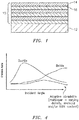
- FIG. 1 shows a coating 10 on a substrate 12, wherein the coating is a multiple layer abradable coating, with individual layers identified at 14, 16.
- the coating is a multiple layer abradable coating, with individual layers identified at 14, 16.
- a plurality of each layer 14, 16 are provided, in alternating fashion as shown, so that substrate 12 is coated by alternating abradable layers 14, 16.
- Abradable coatings are commonly exposed to fluctuation in contact conditions which can lead to severe erosive wear and, consequently, an overall reduction in performance.
- Current coatings are made with various filler materials to provide acceptable properties, but these coatings lead to excessive cost per compressor stage in an engine.
- the disclosed abradable coating produces desirable resistance to erosion even when subjected to fluctuating contact conditions, and does so at a reasonable cost, which can significantly reduce overhaul costs.
- layers 14, 16 have different properties related to erosion resistance.
- One exemplary embodiment of the different properties is different properties with respect to resistance to erosion from particulate impact at different angles of impact or angles of incidence to the abradable coating.
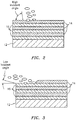
- layers 14 are resistant to erosion when impacted by particles at a high angle of incidence, while layers 16 are resistant to erosion when impacted by particles at a low angle of incidence. Examples of these conditions are shown in FIGS. 2 and 3 , respectively.
- a layer is considered to be resistant to erosion when it has an erosion resistance of less than or equal to 0.05 cm 3 /g, for example as measured by ASTM G76, using a particulate erosion tester at ambient or elevated temperatures, wherein the measure is taken by dividing the volume of loss of material (cm 3 ) by the total mass of particles (g).
- layers 14 can have an erosion resistance against particles impacting from a high angle of incidence of less than or equal to 0.05 cm 3 /g
- layers 16 can have an erosion resistance against particles impacting from a low angle of incidence of less than or equal to 0.05 cm 3 /g.
- the erosion resistance to impacts from the opposite angle i.e., low angle of incidence with a layer 14 or high angle of incidence with a layer 16
- the erosion resistance to impacts from the opposite angle would be higher than the desired 0.05 cm 3 /g.
- erosion of one layer from particles at such an angle would then expose a layer with the desired erosion resistance.
- the materials to be used to provide alternating resistance to erosion at a high angle of incidence in one layer, and resistance to erosion at a low angle of incidence in the next layer can be materials which are more economical than those used in known coating systems.
- the difference in properties between layers 14, 16 is a difference in porosity fraction.
- layer(s) 16, having good resistance against erosion from particulate impact at low angles of incidence can be provided having a porosity fraction of between about 0.02 and 0.1
- layer(s) 14, having good resistance against erosion from particulate impact at high angles of incidence can be provided with a porosity fraction of between about 0.15 and about 0.5.
- This difference in porosity fraction can be provided in layers of the same material by manipulating the coating process and/or material to produce a higher porosity and/or a lower density in one layer, and a lower porosity and/or higher density in the next.
- a layer can be provided with porosity by including an organic binder in the coating material and then burning off or otherwise removing the binder to leave the open space or porosity in the layer.
- Some layers may be produced with substantially no porosity, which is considered to be a layer having a porosity fraction of about 0.02 within the low end of the range discussed above.
- the different property of the layers 14, 16 can be produced by making layers 14, 16 from different materials. These different materials can themselves have different properties, or they can be used in layers having different porosity fraction as discussed above, or both.
- an abradable coating can be produced from alternating layers that are relatively ductile and relatively brittle.
- FIG. 4 shows a relationship between erosion rate and incident angle for such ductile and brittle materials. As illustrated, ductile material has a higher resistance to erosion (i.e. lower erosion rate) at higher incident angles, while brittle material has higher resistance to erosion at lower incident angles.
- the relatively ductile and brittle layers can be formed according to one aspect of this disclosure by forming each layer having different porosity fraction.
- the materials for the layers can be different, for example with the relatively ductile layer being formed from MCrAlY alloy, wherein M can be Ni, Co and combinations thereof, and with the relatively brittle material being zirconia, magnesia, alumina or mixtures thereof.
- M can be Ni, Co and combinations thereof
- the relatively brittle material being zirconia, magnesia, alumina or mixtures thereof.
- One particularly suitable material for the relatively brittle material is zirconia.
- solid lubricants can be added to one or both pluralities of layers to produce and/or supplement the different properties of alternating layers with respect to erosion resistance and/or to improve the overall abradability of the resulting coating.
- These solid lubricants can include, for example, graphene, graphite, graphite intercalation compounds, highly oriented pyrolytic graphite, molybdenum disulfide, clay, black phosphorous, hexagonal boron nitride, tungsten diselenide, rhenium disulfide, and combinations thereof.
- hexagonal boron nitride (hBN) can be included in some or all layers.
- one layer having a thickness of between about 30 and about 100 ⁇ m can contain between about 0 and about 10% wt. hBN, while a following layer having roughly the same thickness can contain between about 30 and about 65% wt. hBN.
- the alternating layers of the abradable coating as disclosed herein can be applied using any known technique, for example including thermal spraying, cold spraying and the like.
- Abradable coating according to this disclosure can advantageously have a thickness for each layer of between about 30 and about 150 ⁇ m.
- the total thickness of the abradable coating, including all layers can advantageously be less than or equal to 400 ⁇ m.
- the thicknesses of the layers and overall assembled coating can be tailored to meet the specific requirements of the application environment. For example, if there is more potential for high angle particle impact, layers resistant to this condition can be increased in thickness and/or in number, and vice versa.
- the brittle layer(s) can have high resistance against erosion due to particles which have a low angle of incidence with a surface of the abradable coating, which is considered to be an angle of between >0 and 30 degrees, as schematically illustrated in FIG. 2 .
- the ductile layer(s) can have high resistance against erosion due to particles having a high angle of incidence with the surface of the abradable coating, which is considered to be an angle between 50 and 90 degrees.
- the procedures of ASTM G76 can be followed, with the angle of incidence being taken at 70 degrees to evaluate the layers having resistance due to particles impacting at a high angle of incidence, and with the angle of incidence being taken at 15 degrees to evaluate the layers having resistance due to particles impacting at a low angle of incidence.
- the layers should have a resistance to erosion at the relevant angle of incidence of less than about 0.05 cm 3 /g as determined by ASTM G76, modified as to the angle as discussed above.
- This interface can be a flat interface, or the interface can be a wavy, interlocked interface, which enhances layer-to-layer bond strength.
- Different characteristics of the interface can be created depending upon the process used to apply each layer, the composition and interaction between compositions of adjacent layers, or both.
- multi-faceted interfaces can be created between layers, and these multi-faceted interfaces or layers can have changes of angle compared to rub and impact erosion.
- Multi-faceted layers that is, an interface with changes of angle compared to rub and impact erosion, can allow for optimal rub and erosion at least at portions of the coating axial length. Therefore, such an interface can provide improvements in seal and erosion protection.
- a multi-faceted interface can produce these areas where optimal erosion protection is produced, while also providing areas where the interface has less optimal performance. However, overall system performance can be improved.
- the interface can also be produced as a graded layer, phasing out of the material of one layer and into the material of the next layer. This can be desirable if a more gradual transition between the properties of erosion resistance is desired.
- the thickness of the graded layer can be selected based also upon how gradual of a transition between properties is desired, and can for example be less than or equal to 10 ⁇ m.
- first and second layers are referred to herein as first and second layers, this is for the purpose of distinguishing between them, and either layer can be the first and/or last layer applied, depending upon the expected conditions to which the coating is to be exposed.
- a bond coat can be applied to a substrate in advance of the multilayer coating disclosed herein, for example to enhance adhesion of the coating to the substrate.
- Suitable materials for the bond coat can be NiCoCrAlY or NiAl as non-limiting examples, or the like.
- a multilayer coating is illustrated wherein a bond coat 18 is applied to the substrate, and wherein there is a graded layer 20 between layers 14, 16 of the multilayer coating.
- the graded layer is a transition layer from the material of one layer 14 to the material of the other layer 16, and these graded layers can have a thickness of less than or equal to about 10 ⁇ m.
- an interface 22 between layers 14, 16 is illustrated and in this case can have a wavy shape as discussed above. Similarly, this interface could be multi-faceted, as such a configuration can provide desirable properties of enhanced erosion resistance.
- the abradable coated part disclosed herein typically defines a seal with another component, for example a moving component of a compressor such as a fan blade.
- FIG. 7 shows substrate 12 with coating 10, and a component or fan blade 24 which can have an abrasive coating (not shown) and which is intended to abrade coating 10 during operation of these components 12, 24.
- a seal 26 between components 12, 24 is maintained for an extended useful lifetime of the components by a controlled abrasion during rub of component 24 against component 12 during such operation.
- desired abradability of coating 12 is maintained, even when coating 12 is exposed to potentially varying erosion factors due to the alternating layers having enhanced resistance to erosion from different angles of incidence which serve to keep an effective amount of the coating in place during an extended period of use.
- an abradable coating can be applied to a substrate following a method wherein first and second abradable layers can be applied to the substrate, and the first and second abradable layers have different properties related to erosion resistance.
- the process can be repeated to apply as many first and second abradable layers as desired, and further can be modified to have multiple or thicker first or second layers, depending upon the angle of impact of expected erosion conditions to which the coated part is to be subjected.
- a bond coat layer with a thickness between 200 and 300 ⁇ m is desired and can be applied between the substrate and the first layer.
- the first layer contains MCrAlY alloy and has porosity generated by burning off or otherwise removal of the organic binder such that the porosity fraction for this layer would be about 0.32.
- the second layer contains zirconium oxide and has substantially no porosity fraction, corresponding to a porosity fraction of about 0.02.
- the 10 ⁇ m graded layer listed between first and second layers is a graded layer which transitions from the material of the first layer to the material of the second layer. In other words, at a mid-point of the graded layer, the composition would be approximately 50% material of the first layer and 50% material of the second layer.
- the different combined features of these layers produces good erosion resistance for the first layer against erosion from particles impacting at a high angle of incidence, while the second layer has a good erosion resistance from particles impacting at a low angle of incidence.
- the overall multilayer structure is abradable as desired, and this multilayer structure or coating can be applied at less cost than other known abradable coatings.
- a bond coat layer having a thickness between 200 and 300 ⁇ m is applied to the substrate. Then the following layers are applied over the bond coat.
- the first and second layers are made from substantially the same material, with hBN being included only in the second layer, and with the first layer being provided with a porosity fraction of about 0.37.
- the second layer is substantially non-porous, having a porosity fraction of about 0.02. The added hBN enhances abradability of the multilayer structure, while the porosity fraction of the first layer provides this layer with greater resistance to erosion from particles impacting at a high angle of incidence, and the second layer provides greater resistance to erosion from particles impacting at a low angle of incidence.
Landscapes
- Chemical & Material Sciences (AREA)
- Engineering & Computer Science (AREA)
- Mechanical Engineering (AREA)
- Materials Engineering (AREA)
- Organic Chemistry (AREA)
- Metallurgy (AREA)
- Chemical Kinetics & Catalysis (AREA)
- Inorganic Chemistry (AREA)
- General Engineering & Computer Science (AREA)
- Composite Materials (AREA)
- Ceramic Engineering (AREA)
- Physics & Mathematics (AREA)
- Plasma & Fusion (AREA)
- Structures Of Non-Positive Displacement Pumps (AREA)
Abstract
Description
- The present disclosure is directed to abradable coatings for turbofan engine components such as compressor components.
- Certain components of gas turbines and compressors call for as little clearance as possible between them in order to enhance a seal between the components and limit leakage of gas between the components and the resulting loss in efficiency. These components can be designed to occasionally rub or impact each other, and an abradable surface or coating can be applied or disposed on one or both of the components.
- It is desired that abradable coatings be abradable when rubbed by an adjacent moving component, which for example can have an abrasive surface designed to abrade the abradable coating. It is still also desired, however, that such abradable surface or coating be erosion resistant.
- Depending upon the operating conditions of the gas turbine or compressor, erosive particles can impact the coating from various angles.
- According to the disclosure, a coating is provided which is abradable and also retains good erosion resistance in various different conditions of erosion.
- In one aspect, the disclosure relates to a multilayer abradable coating which comprises at least one first abradable layer; and at least one second abradable layer, wherein the first abradable layer and the second abradable layer have different properties related to erosion resistance.
- In an embodiment of the above, the first abradable layer has higher erosion resistance than the second abradable layer against impacts at a high angle of incidence, and the second abradable layer has higher erosion resistance than the first abradable layer against impacts at a low angle of incidence.
- In another embodiment of any of the above, the first abradable layer has a higher porosity fraction than the second abradable layer.
- In another embodiment of any of the above, the first abradable layer has a porosity fraction of between about 0.15 and about 0.5, and the second abradable layer has a porosity fraction of between about 0.02 and about 0.1.
- In another embodiment of any of the above, the first abradable layer comprises a MCrAlY alloy where M is Ni, Co or NiCo, and the second abradable layer comprises zirconia, magnesia, alumina or combinations thereof.
- In another embodiment of any of the above, at least one of the first abradable layer and the second abradable layer further comprises a solid lubricant.
- In another embodiment of any of the above, the solid lubricant is selected from the group consisting of graphene, graphite, graphite intercalation compounds, highly oriented pyrolytic graphite, molybdenum disulfide, clay, black phosphorous, hexagonal boron nitride, tungsten diselenide, rhenium disulfide, and combinations thereof.
- In another aspect of the disclosure, an abradable coated part of a compressor is provided, comprising a substrate; and a multilayer abradable coating on the substrate, the coating comprising at least one first abradable layer; and at least one second abradable layer, wherein the first abradable layer and the second abradable layer have different properties related to erosion resistance. The compressor may be a gas turbine engine compressor and/or the coated part may be a blade, such as a compressor or fan blade.
- In another aspect of the disclosure, an abradable seal between two components of a compressor is provided, which comprises a coated part as disclosed herein and an abrasive part moveable relative to the coated part and configured to rub and abrade the coated part. The compressor may be a gas turbine engine compressor and/or the coated part may be a blade, such as a compressor or fan blade.
- In another aspect of the disclosure, a method for applying an abradable coating to a substrate is provided, which comprises the steps of: applying a first abradable layer to the substrate; and applying a second abradable layer over the first abradable layer, wherein the first abradable layer and the second abradable layer have different properties related to erosion resistance.
- A detailed disclosure of exemplary embodiments follows, with reference to the attached drawings, wherein:
-
FIG. 1 illustrates a multilayer abradable coating; -
FIG. 2 illustrates impact of erosive particles with a multilayer abradable coating from a high angle of incidence; -
FIG. 3 illustrates impact of erosive particles with a multilayer abradable coating from a low angle of incidence; -
FIG. 4 illustrates a relationship between incident angle and erosion for ductile and brittle layers of a multilayer abradable coating; -
FIG. 5 illustrates a multilayer abradable coating including bond coat and graded layers; -
FIG. 6 illustrates a wavy interface between layers; and -
FIG. 7 schematically illustrates a seal between an abradable coated substrate and abrasive part which moves relative to the substrate. - The disclosure relates to an abradable coating for use in providing desired abradability along with resistance to erosion, with a coating that is also more economical than known coatings.
-
FIG. 1 shows acoating 10 on asubstrate 12, wherein the coating is a multiple layer abradable coating, with individual layers identified at 14, 16. In the exemplary embodiment, a plurality of eachlayer substrate 12 is coated by alternatingabradable layers - Abradable coatings are commonly exposed to fluctuation in contact conditions which can lead to severe erosive wear and, consequently, an overall reduction in performance. Current coatings are made with various filler materials to provide acceptable properties, but these coatings lead to excessive cost per compressor stage in an engine. The disclosed abradable coating produces desirable resistance to erosion even when subjected to fluctuating contact conditions, and does so at a reasonable cost, which can significantly reduce overhaul costs.
- In an exemplary embodiment,
layers layers 14 are resistant to erosion when impacted by particles at a high angle of incidence, whilelayers 16 are resistant to erosion when impacted by particles at a low angle of incidence. Examples of these conditions are shown inFIGS. 2 and 3 , respectively. In this regard, a layer is considered to be resistant to erosion when it has an erosion resistance of less than or equal to 0.05 cm3/g, for example as measured by ASTM G76, using a particulate erosion tester at ambient or elevated temperatures, wherein the measure is taken by dividing the volume of loss of material (cm3) by the total mass of particles (g). As it relates to the present disclosure, in an exemplary embodiment,layers 14 can have an erosion resistance against particles impacting from a high angle of incidence of less than or equal to 0.05 cm3/g, andlayers 16 can have an erosion resistance against particles impacting from a low angle of incidence of less than or equal to 0.05 cm3/g. In each case, the erosion resistance to impacts from the opposite angle, i.e., low angle of incidence with alayer 14 or high angle of incidence with alayer 16, would be higher than the desired 0.05 cm3/g. However, erosion of one layer from particles at such an angle would then expose a layer with the desired erosion resistance. - When a multilayer coating according to the disclosure encounters fluctuating erosion conditions, for example a change in angle of incidence from the condition of
FIG. 2 to the condition ofFIG. 3 , the now-low angle of incidence particle contact will erode onelayer 14 as shown inFIG. 3 , but will then encounter alayer 16 which is resistant to erosion at low angles of incidence. In this way, fluctuation in erosion conditions results in erosion of one layer but then preservation of the remaining multilayer coating such that the coating has an extended lifetime. Further, when preparing such a multilayer coating, the materials to be used to provide alternating resistance to erosion at a high angle of incidence in one layer, and resistance to erosion at a low angle of incidence in the next layer, can be materials which are more economical than those used in known coating systems. - In an exemplary embodiment, the difference in properties between
layers - In an alternative exemplary embodiment, the different property of the
layers layers - In order to provide the desired alternating layers having different erosion resistance, an abradable coating can be produced from alternating layers that are relatively ductile and relatively brittle.
FIG. 4 shows a relationship between erosion rate and incident angle for such ductile and brittle materials. As illustrated, ductile material has a higher resistance to erosion (i.e. lower erosion rate) at higher incident angles, while brittle material has higher resistance to erosion at lower incident angles. - As set forth above, the relatively ductile and brittle layers can be formed according to one aspect of this disclosure by forming each layer having different porosity fraction.
- Alternatively, or in addition, the materials for the layers can be different, for example with the relatively ductile layer being formed from MCrAlY alloy, wherein M can be Ni, Co and combinations thereof, and with the relatively brittle material being zirconia, magnesia, alumina or mixtures thereof. One particularly suitable material for the relatively brittle material is zirconia.
- In addition, solid lubricants can be added to one or both pluralities of layers to produce and/or supplement the different properties of alternating layers with respect to erosion resistance and/or to improve the overall abradability of the resulting coating. These solid lubricants can include, for example, graphene, graphite, graphite intercalation compounds, highly oriented pyrolytic graphite, molybdenum disulfide, clay, black phosphorous, hexagonal boron nitride, tungsten diselenide, rhenium disulfide, and combinations thereof. In one exemplary embodiment, hexagonal boron nitride (hBN) can be included in some or all layers. For example, one layer having a thickness of between about 30 and about 100 µm can contain between about 0 and about 10% wt. hBN, while a following layer having roughly the same thickness can contain between about 30 and about 65% wt. hBN.
- The alternating layers of the abradable coating as disclosed herein can be applied using any known technique, for example including thermal spraying, cold spraying and the like.
- Abradable coating according to this disclosure can advantageously have a thickness for each layer of between about 30 and about 150 µm. In addition, the total thickness of the abradable coating, including all layers, can advantageously be less than or equal to 400 µm. The thicknesses of the layers and overall assembled coating can be tailored to meet the specific requirements of the application environment. For example, if there is more potential for high angle particle impact, layers resistant to this condition can be increased in thickness and/or in number, and vice versa.
- In another exemplary embodiment, the brittle layer(s) can have high resistance against erosion due to particles which have a low angle of incidence with a surface of the abradable coating, which is considered to be an angle of between >0 and 30 degrees, as schematically illustrated in
FIG. 2 . Furthermore, the ductile layer(s) can have high resistance against erosion due to particles having a high angle of incidence with the surface of the abradable coating, which is considered to be an angle between 50 and 90 degrees. In connection with measurement of erosion resistance for these layers, the procedures of ASTM G76 can be followed, with the angle of incidence being taken at 70 degrees to evaluate the layers having resistance due to particles impacting at a high angle of incidence, and with the angle of incidence being taken at 15 degrees to evaluate the layers having resistance due to particles impacting at a low angle of incidence. In each case, the layers should have a resistance to erosion at the relevant angle of incidence of less than about 0.05 cm3/g as determined by ASTM G76, modified as to the angle as discussed above. - It should be noted that there is an interface between layers of the system according to the disclosure. This interface can be a flat interface, or the interface can be a wavy, interlocked interface, which enhances layer-to-layer bond strength. Different characteristics of the interface can be created depending upon the process used to apply each layer, the composition and interaction between compositions of adjacent layers, or both. Further, depending upon the materials and processes used, multi-faceted interfaces can be created between layers, and these multi-faceted interfaces or layers can have changes of angle compared to rub and impact erosion. Multi-faceted layers, that is, an interface with changes of angle compared to rub and impact erosion, can allow for optimal rub and erosion at least at portions of the coating axial length. Therefore, such an interface can provide improvements in seal and erosion protection. A multi-faceted interface can produce these areas where optimal erosion protection is produced, while also providing areas where the interface has less optimal performance. However, overall system performance can be improved.
- It should also be noted that the interface can also be produced as a graded layer, phasing out of the material of one layer and into the material of the next layer. This can be desirable if a more gradual transition between the properties of erosion resistance is desired. The thickness of the graded layer can be selected based also upon how gradual of a transition between properties is desired, and can for example be less than or equal to 10 µm.
- It should still further be noted that although the different types of layers are referred to herein as first and second layers, this is for the purpose of distinguishing between them, and either layer can be the first and/or last layer applied, depending upon the expected conditions to which the coating is to be exposed.
- In a further aspect of the disclosure, a bond coat can be applied to a substrate in advance of the multilayer coating disclosed herein, for example to enhance adhesion of the coating to the substrate. Suitable materials for the bond coat can be NiCoCrAlY or NiAl as non-limiting examples, or the like.
- Referring to
FIG. 5 , a multilayer coating is illustrated wherein a bond coat 18 is applied to the substrate, and wherein there is a gradedlayer 20 betweenlayers layer 14 to the material of theother layer 16, and these graded layers can have a thickness of less than or equal to about 10 µm. - Referring to
FIG. 6 , aninterface 22 betweenlayers - As set forth above, the abradable coated part disclosed herein typically defines a seal with another component, for example a moving component of a compressor such as a fan blade.
FIG. 7 showssubstrate 12 withcoating 10, and a component orfan blade 24 which can have an abrasive coating (not shown) and which is intended to abradecoating 10 during operation of thesecomponents seal 26 betweencomponents component 24 againstcomponent 12 during such operation. As disclosed herein, desired abradability ofcoating 12 is maintained, even when coating 12 is exposed to potentially varying erosion factors due to the alternating layers having enhanced resistance to erosion from different angles of incidence which serve to keep an effective amount of the coating in place during an extended period of use. - In another aspect of the disclosure, an abradable coating can be applied to a substrate following a method wherein first and second abradable layers can be applied to the substrate, and the first and second abradable layers have different properties related to erosion resistance. The process can be repeated to apply as many first and second abradable layers as desired, and further can be modified to have multiple or thicker first or second layers, depending upon the angle of impact of expected erosion conditions to which the coated part is to be subjected.
- Illustrative examples of multilayer coatings are provided below.
-
- First layer:
- Nickel, chromium, aluminum
- 5-10% wt. hBN
- <2% wt. additional elements
- Cobalt as remainder
- 6% wt. organic binder (leads to porosity fraction of about 0.32)
- Graded layer: ≤10µm
- Second layer:
- 7% Yttrium oxide
- <3% additional elements (e.g. hafnium oxide)
Zirconium oxide as remainder. - Graded layer: ≤10µm
- Third layer: same as first layer
- Graded layer: ≤10µm
- Fourth layer: same as second layer
- Repeated layers may be added as needed.
- In the above example, a bond coat layer with a thickness between 200 and 300 µm is desired and can be applied between the substrate and the first layer.
- The first layer contains MCrAlY alloy and has porosity generated by burning off or otherwise removal of the organic binder such that the porosity fraction for this layer would be about 0.32. The second layer contains zirconium oxide and has substantially no porosity fraction, corresponding to a porosity fraction of about 0.02.
- The 10µm graded layer listed between first and second layers is a graded layer which transitions from the material of the first layer to the material of the second layer. In other words, at a mid-point of the graded layer, the composition would be approximately 50% material of the first layer and 50% material of the second layer.
- The different combined features of these layers produces good erosion resistance for the first layer against erosion from particles impacting at a high angle of incidence, while the second layer has a good erosion resistance from particles impacting at a low angle of incidence. Further, the overall multilayer structure is abradable as desired, and this multilayer structure or coating can be applied at less cost than other known abradable coatings.
- In this example, a bond coat layer having a thickness between 200 and 300 µm is applied to the substrate. Then the following layers are applied over the bond coat.
- First layer (no hBN):
- Chromium, aluminum, tungsten, molybdenum, tantalum <2% wt. additional elements
- Nickel as the remainder
- 6% wt. organic binder (leads to a porosity fraction of about 0.37).
- Second layer (with hBN):
- Chromium, aluminum, tungsten, molybdenum, tantalum <2% additional elements
- Nickel as the remainder
- 5-10% wt. hBN.
- Third layer: same as first layer
- Fourth layer: same as second layer
- Repeated layers may be added as needed.
- In the above structure, the first and second layers are made from substantially the same material, with hBN being included only in the second layer, and with the first layer being provided with a porosity fraction of about 0.37. The second layer is substantially non-porous, having a porosity fraction of about 0.02. The added hBN enhances abradability of the multilayer structure, while the porosity fraction of the first layer provides this layer with greater resistance to erosion from particles impacting at a high angle of incidence, and the second layer provides greater resistance to erosion from particles impacting at a low angle of incidence.
- There has been provided a multilayer abradable coating for turbines and compressors, which has a plurality of alternating different layers to provide different resistance to erosion depending upon the conditions of erosion to which the coating is exposed. While the disclosure has been made in the context of specific embodiments thereof, other unforeseen alternatives, modifications, and variations may become apparent to those skilled in the art having read the foregoing description. Accordingly, it is intended to embrace those alternatives, modifications, and variations that fall within the broad scope of the appended claims.
Claims (12)
- A multilayer abradable coating (10), comprising:at least one first abradable layer (16); andat least one second abradable layer (14), wherein the first abradable layer (16) and the second abradable layer (14) have different properties related to erosion resistance.
- An abradable coated part of a compressor, comprising:a substrate (12); andthe multilayer abradable coating (10) of claim 1 on the substrate (12).
- The coating or coated part of claim 1 or 2, wherein the first abradable layer (14) has higher erosion resistance than the second abradable layer (16) against impacts at a high angle of incidence, and the second abradable layer (16) has higher erosion resistance than the first abradable layer (14) against impacts at a low angle of incidence.
- The coating or coated part of any preceding claim, wherein the first abradable layer (14) has a higher porosity fraction than the second abradable layer (16).
- The coating or coated part of claim 4, wherein the first abradable layer (14) has a porosity fraction of between about 0.15 and about 0.5, and the second abradable layer (16) has a porosity fraction of between about 0.02 and about 0.1.
- The coating or coated part of any preceding claim, wherein the first abradable layer (14) comprises a MCrAlY alloy where M is Ni, Co or NiCo, and the second abradable layer (16) comprises zirconia, magnesia, alumina or combinations thereof.
- The coating or coated part of any preceding claim, wherein at least one of the first abradable layer (14) and the second abradable layer (16) comprises a solid lubricant.
- The coating or coated part of claim 7, wherein the solid lubricant is graphene, graphite, graphite intercalation compounds, highly oriented pyrolytic graphite, molybdenum disulfide, clay, black phosphorous, hexagonal boron nitride, tungsten diselenide, rhenium disulfide, or combinations thereof.
- An abradable seal (26) between two components of a compressor, comprising:a coated part according to any of claims 2 to 8; andan abrasive part (24) moveable relative to the coated part and configured to rub and abrade the coated part.
- A method for applying an abradable coating (10) to a substrate (12), comprising the steps of:applying a first abradable layer (14) to the substrate (12); andapplying a second abradable layer (16) over the first abradable layer (14), wherein the first abradable layer (14) and the second abradable layer (16) have different properties related to erosion resistance.
- The method of claim 10, further comprising repeating the applying steps to produce a desired plurality of alternating first abradable layers (14) and second abradable layers (16).
- The method of claim 10 or 11, wherein the applying steps comprise thermal spraying, cold spraying or combinations thereof.
Applications Claiming Priority (1)
| Application Number | Priority Date | Filing Date | Title |
|---|---|---|---|
| US15/430,783 US11209010B2 (en) | 2017-02-13 | 2017-02-13 | Multilayer abradable coating |
Publications (2)
| Publication Number | Publication Date |
|---|---|
| EP3360985A1 true EP3360985A1 (en) | 2018-08-15 |
| EP3360985B1 EP3360985B1 (en) | 2020-04-01 |
Family
ID=61223714
Family Applications (1)
| Application Number | Title | Priority Date | Filing Date |
|---|---|---|---|
| EP18156006.1A Active EP3360985B1 (en) | 2017-02-13 | 2018-02-09 | Multilayer abradable coating |
Country Status (2)
| Country | Link |
|---|---|
| US (1) | US11209010B2 (en) |
| EP (1) | EP3360985B1 (en) |
Families Citing this family (3)
| Publication number | Priority date | Publication date | Assignee | Title |
|---|---|---|---|---|
| FR3099186B1 (en) * | 2019-07-23 | 2023-04-14 | Safran Aircraft Engines | Method of manufacturing an abradable sealing element, and abradable sealing element |
| CN113150234B (en) * | 2021-05-10 | 2022-06-24 | 慕思健康睡眠股份有限公司 | A kind of wear-resistant graphene polyurethane composite sponge material and preparation method and application thereof |
| CN118620421B (en) * | 2024-04-30 | 2025-09-26 | 荣耀终端股份有限公司 | Composite coatings, display modules and electronic devices |
Citations (8)
| Publication number | Priority date | Publication date | Assignee | Title |
|---|---|---|---|---|
| GB2121884A (en) * | 1982-06-17 | 1984-01-04 | United Technologies Corp | Ceramic faced outer air seal for gas turbine engines |
| EP0187612A2 (en) * | 1984-12-24 | 1986-07-16 | United Technologies Corporation | Abradable seal having particulate erosion resistance |
| WO2008054340A2 (en) * | 2005-08-16 | 2008-05-08 | Honeywell International Inc. | Multilayered erosion resistant coating for gas turbines |
| EP2281913A1 (en) * | 2009-08-03 | 2011-02-09 | United Technologies Corporation | Lubricated abradable coating |
| EP2372104A2 (en) * | 2010-04-01 | 2011-10-05 | United Technologies Corporation | Blade outer air seal with improved efficiency |
| WO2012122373A1 (en) * | 2011-03-09 | 2012-09-13 | Rolls-Royce Corporation | Abradable layer including a low thermal conductivity composition |
| EP2574727A1 (en) * | 2011-09-27 | 2013-04-03 | United Technologies Corporation | Blade air seal with integral thermal barrier corresponding gas turbine engine and method of manufacturing |
| EP3239475A1 (en) * | 2016-04-25 | 2017-11-01 | United Technologies Corporation | Outer airseal abradable rub strip |
Family Cites Families (12)
| Publication number | Priority date | Publication date | Assignee | Title |
|---|---|---|---|---|
| US5702829A (en) * | 1991-10-14 | 1997-12-30 | Commissariat A L'energie Atomique | Multilayer material, anti-erosion and anti-abrasion coating incorporating said multilayer material |
| US6102656A (en) * | 1995-09-26 | 2000-08-15 | United Technologies Corporation | Segmented abradable ceramic coating |
| US6352264B1 (en) * | 1999-12-17 | 2002-03-05 | United Technologies Corporation | Abradable seal having improved properties |
| US6660405B2 (en) * | 2001-05-24 | 2003-12-09 | General Electric Co. | High temperature abradable coating for turbine shrouds without bucket tipping |
| US20050003172A1 (en) * | 2002-12-17 | 2005-01-06 | General Electric Company | 7FAstage 1 abradable coatings and method for making same |
| US20080107920A1 (en) * | 2006-01-06 | 2008-05-08 | Raymond Grant Rowe | Thermal barrier coated articles and methods of making the same |
| US8142252B1 (en) | 2008-10-03 | 2012-03-27 | Krull Mark A | Amusement methods and apparatus |
| US8470460B2 (en) * | 2008-11-25 | 2013-06-25 | Rolls-Royce Corporation | Multilayer thermal barrier coatings |
| US8124252B2 (en) * | 2008-11-25 | 2012-02-28 | Rolls-Royce Corporation | Abradable layer including a rare earth silicate |
| FR2947922B1 (en) | 2009-07-10 | 2011-12-09 | Polymage | METHOD FOR MANUFACTURING AN ADAPTIVE COATING |
| US8852720B2 (en) * | 2009-07-17 | 2014-10-07 | Rolls-Royce Corporation | Substrate features for mitigating stress |
| AT510697B1 (en) | 2011-05-11 | 2012-06-15 | High Tech Coatings Gmbh | COMPONENT WITH AN ADAPTIVE COATING |
-
2017
- 2017-02-13 US US15/430,783 patent/US11209010B2/en active Active
-
2018
- 2018-02-09 EP EP18156006.1A patent/EP3360985B1/en active Active
Patent Citations (8)
| Publication number | Priority date | Publication date | Assignee | Title |
|---|---|---|---|---|
| GB2121884A (en) * | 1982-06-17 | 1984-01-04 | United Technologies Corp | Ceramic faced outer air seal for gas turbine engines |
| EP0187612A2 (en) * | 1984-12-24 | 1986-07-16 | United Technologies Corporation | Abradable seal having particulate erosion resistance |
| WO2008054340A2 (en) * | 2005-08-16 | 2008-05-08 | Honeywell International Inc. | Multilayered erosion resistant coating for gas turbines |
| EP2281913A1 (en) * | 2009-08-03 | 2011-02-09 | United Technologies Corporation | Lubricated abradable coating |
| EP2372104A2 (en) * | 2010-04-01 | 2011-10-05 | United Technologies Corporation | Blade outer air seal with improved efficiency |
| WO2012122373A1 (en) * | 2011-03-09 | 2012-09-13 | Rolls-Royce Corporation | Abradable layer including a low thermal conductivity composition |
| EP2574727A1 (en) * | 2011-09-27 | 2013-04-03 | United Technologies Corporation | Blade air seal with integral thermal barrier corresponding gas turbine engine and method of manufacturing |
| EP3239475A1 (en) * | 2016-04-25 | 2017-11-01 | United Technologies Corporation | Outer airseal abradable rub strip |
Also Published As
| Publication number | Publication date |
|---|---|
| US20180231014A1 (en) | 2018-08-16 |
| US11209010B2 (en) | 2021-12-28 |
| EP3360985B1 (en) | 2020-04-01 |
Similar Documents
| Publication | Publication Date | Title |
|---|---|---|
| US9581041B2 (en) | Abradable ceramic coatings and coating systems | |
| US7510370B2 (en) | Turbine blade tip and shroud clearance control coating system | |
| CN108431290B (en) | Turbine Clearance Control Coatings and Methods | |
| KR100597498B1 (en) | Columnar zirconium oxide abrasive coating for a gas turbine engine seal system | |
| US9511436B2 (en) | Composite composition for turbine blade tips, related articles, and methods | |
| US9926794B2 (en) | Turbine blade tip treatment for industrial gas turbines | |
| EP1908925B1 (en) | Ternary carbide and nitrate abradable seal by thermal vaporisation | |
| US20070099027A1 (en) | Wear resistant coatings | |
| US10774669B2 (en) | Low permeability high pressure compressor abradable seal for bare ni airfoils having continuous metal matrix | |
| US7473072B2 (en) | Turbine blade tip and shroud clearance control coating system | |
| US9260784B2 (en) | Blade tip coating that can be rubbed off | |
| WO2003061961A1 (en) | Multilayer thermal barrier coating | |
| CN102286744A (en) | Wear-resistant and low-friction coatings and articles coated therewith | |
| US20140272166A1 (en) | Coating system for improved leading edge erosion protection | |
| EP3360985B1 (en) | Multilayer abradable coating | |
| CN113423855A (en) | Dense abradable coating with brittle and abradable components | |
| EP1927670A1 (en) | Wear resistant coatings | |
| WO2021055004A1 (en) | Turbine engine abradable systems | |
| Arendarchuck et al. | Tribological evaluation of Cu-based abradable coating | |
| EP3626850B1 (en) | Bond coat for spallation resistant ceramic coating | |
| US8974588B2 (en) | Coating composition, a process of applying a coating, and a process of forming a coating composition | |
| Bheekhun et al. | Thermal spray coatings for polymer matrix composites in gas turbine engines: A literary preview | |
| JP2008138242A (en) | Abrasion resistant coating and article having the abrasion resistant coating | |
| JP2011241800A (en) | Coating having corrosion resistance at high temperature | |
| JP2018535322A (en) | Turbine clearance control coating and method |
Legal Events
| Date | Code | Title | Description |
|---|---|---|---|
| PUAI | Public reference made under article 153(3) epc to a published international application that has entered the european phase |
Free format text: ORIGINAL CODE: 0009012 |
|
| STAA | Information on the status of an ep patent application or granted ep patent |
Free format text: STATUS: THE APPLICATION HAS BEEN PUBLISHED |
|
| AK | Designated contracting states |
Kind code of ref document: A1 Designated state(s): AL AT BE BG CH CY CZ DE DK EE ES FI FR GB GR HR HU IE IS IT LI LT LU LV MC MK MT NL NO PL PT RO RS SE SI SK SM TR |
|
| AX | Request for extension of the european patent |
Extension state: BA ME |
|
| STAA | Information on the status of an ep patent application or granted ep patent |
Free format text: STATUS: REQUEST FOR EXAMINATION WAS MADE |
|
| 17P | Request for examination filed |
Effective date: 20190215 |
|
| RBV | Designated contracting states (corrected) |
Designated state(s): AL AT BE BG CH CY CZ DE DK EE ES FI FR GB GR HR HU IE IS IT LI LT LU LV MC MK MT NL NO PL PT RO RS SE SI SK SM TR |
|
| GRAP | Despatch of communication of intention to grant a patent |
Free format text: ORIGINAL CODE: EPIDOSNIGR1 |
|
| STAA | Information on the status of an ep patent application or granted ep patent |
Free format text: STATUS: GRANT OF PATENT IS INTENDED |
|
| RIC1 | Information provided on ipc code assigned before grant |
Ipc: C23C 28/02 20060101ALI20190318BHEP Ipc: F01D 5/28 20060101ALI20190318BHEP Ipc: F01D 11/12 20060101ALI20190318BHEP Ipc: C23C 28/00 20060101AFI20190318BHEP |
|
| INTG | Intention to grant announced |
Effective date: 20190408 |
|
| GRAJ | Information related to disapproval of communication of intention to grant by the applicant or resumption of examination proceedings by the epo deleted |
Free format text: ORIGINAL CODE: EPIDOSDIGR1 |
|
| STAA | Information on the status of an ep patent application or granted ep patent |
Free format text: STATUS: REQUEST FOR EXAMINATION WAS MADE |
|
| INTC | Intention to grant announced (deleted) | ||
| GRAP | Despatch of communication of intention to grant a patent |
Free format text: ORIGINAL CODE: EPIDOSNIGR1 |
|
| STAA | Information on the status of an ep patent application or granted ep patent |
Free format text: STATUS: GRANT OF PATENT IS INTENDED |
|
| INTG | Intention to grant announced |
Effective date: 20191010 |
|
| GRAS | Grant fee paid |
Free format text: ORIGINAL CODE: EPIDOSNIGR3 |
|
| GRAA | (expected) grant |
Free format text: ORIGINAL CODE: 0009210 |
|
| STAA | Information on the status of an ep patent application or granted ep patent |
Free format text: STATUS: THE PATENT HAS BEEN GRANTED |
|
| AK | Designated contracting states |
Kind code of ref document: B1 Designated state(s): AL AT BE BG CH CY CZ DE DK EE ES FI FR GB GR HR HU IE IS IT LI LT LU LV MC MK MT NL NO PL PT RO RS SE SI SK SM TR |
|
| REG | Reference to a national code |
Ref country code: GB Ref legal event code: FG4D |
|
| REG | Reference to a national code |
Ref country code: AT Ref legal event code: REF Ref document number: 1251425 Country of ref document: AT Kind code of ref document: T Effective date: 20200415 Ref country code: CH Ref legal event code: EP |
|
| REG | Reference to a national code |
Ref country code: DE Ref legal event code: R096 Ref document number: 602018003334 Country of ref document: DE |
|
| REG | Reference to a national code |
Ref country code: IE Ref legal event code: FG4D |
|
| PG25 | Lapsed in a contracting state [announced via postgrant information from national office to epo] |
Ref country code: BG Free format text: LAPSE BECAUSE OF FAILURE TO SUBMIT A TRANSLATION OF THE DESCRIPTION OR TO PAY THE FEE WITHIN THE PRESCRIBED TIME-LIMIT Effective date: 20200701 |
|
| REG | Reference to a national code |
Ref country code: NL Ref legal event code: MP Effective date: 20200401 |
|
| REG | Reference to a national code |
Ref country code: LT Ref legal event code: MG4D |
|
| PG25 | Lapsed in a contracting state [announced via postgrant information from national office to epo] |
Ref country code: CZ Free format text: LAPSE BECAUSE OF FAILURE TO SUBMIT A TRANSLATION OF THE DESCRIPTION OR TO PAY THE FEE WITHIN THE PRESCRIBED TIME-LIMIT Effective date: 20200401 Ref country code: NL Free format text: LAPSE BECAUSE OF FAILURE TO SUBMIT A TRANSLATION OF THE DESCRIPTION OR TO PAY THE FEE WITHIN THE PRESCRIBED TIME-LIMIT Effective date: 20200401 Ref country code: FI Free format text: LAPSE BECAUSE OF FAILURE TO SUBMIT A TRANSLATION OF THE DESCRIPTION OR TO PAY THE FEE WITHIN THE PRESCRIBED TIME-LIMIT Effective date: 20200401 Ref country code: PT Free format text: LAPSE BECAUSE OF FAILURE TO SUBMIT A TRANSLATION OF THE DESCRIPTION OR TO PAY THE FEE WITHIN THE PRESCRIBED TIME-LIMIT Effective date: 20200817 Ref country code: LT Free format text: LAPSE BECAUSE OF FAILURE TO SUBMIT A TRANSLATION OF THE DESCRIPTION OR TO PAY THE FEE WITHIN THE PRESCRIBED TIME-LIMIT Effective date: 20200401 Ref country code: NO Free format text: LAPSE BECAUSE OF FAILURE TO SUBMIT A TRANSLATION OF THE DESCRIPTION OR TO PAY THE FEE WITHIN THE PRESCRIBED TIME-LIMIT Effective date: 20200701 Ref country code: GR Free format text: LAPSE BECAUSE OF FAILURE TO SUBMIT A TRANSLATION OF THE DESCRIPTION OR TO PAY THE FEE WITHIN THE PRESCRIBED TIME-LIMIT Effective date: 20200702 Ref country code: IS Free format text: LAPSE BECAUSE OF FAILURE TO SUBMIT A TRANSLATION OF THE DESCRIPTION OR TO PAY THE FEE WITHIN THE PRESCRIBED TIME-LIMIT Effective date: 20200801 Ref country code: SE Free format text: LAPSE BECAUSE OF FAILURE TO SUBMIT A TRANSLATION OF THE DESCRIPTION OR TO PAY THE FEE WITHIN THE PRESCRIBED TIME-LIMIT Effective date: 20200401 |
|
| REG | Reference to a national code |
Ref country code: AT Ref legal event code: MK05 Ref document number: 1251425 Country of ref document: AT Kind code of ref document: T Effective date: 20200401 |
|
| PG25 | Lapsed in a contracting state [announced via postgrant information from national office to epo] |
Ref country code: HR Free format text: LAPSE BECAUSE OF FAILURE TO SUBMIT A TRANSLATION OF THE DESCRIPTION OR TO PAY THE FEE WITHIN THE PRESCRIBED TIME-LIMIT Effective date: 20200401 Ref country code: RS Free format text: LAPSE BECAUSE OF FAILURE TO SUBMIT A TRANSLATION OF THE DESCRIPTION OR TO PAY THE FEE WITHIN THE PRESCRIBED TIME-LIMIT Effective date: 20200401 Ref country code: LV Free format text: LAPSE BECAUSE OF FAILURE TO SUBMIT A TRANSLATION OF THE DESCRIPTION OR TO PAY THE FEE WITHIN THE PRESCRIBED TIME-LIMIT Effective date: 20200401 |
|
| PG25 | Lapsed in a contracting state [announced via postgrant information from national office to epo] |
Ref country code: AL Free format text: LAPSE BECAUSE OF FAILURE TO SUBMIT A TRANSLATION OF THE DESCRIPTION OR TO PAY THE FEE WITHIN THE PRESCRIBED TIME-LIMIT Effective date: 20200401 |
|
| REG | Reference to a national code |
Ref country code: DE Ref legal event code: R097 Ref document number: 602018003334 Country of ref document: DE |
|
| PG25 | Lapsed in a contracting state [announced via postgrant information from national office to epo] |
Ref country code: RO Free format text: LAPSE BECAUSE OF FAILURE TO SUBMIT A TRANSLATION OF THE DESCRIPTION OR TO PAY THE FEE WITHIN THE PRESCRIBED TIME-LIMIT Effective date: 20200401 Ref country code: ES Free format text: LAPSE BECAUSE OF FAILURE TO SUBMIT A TRANSLATION OF THE DESCRIPTION OR TO PAY THE FEE WITHIN THE PRESCRIBED TIME-LIMIT Effective date: 20200401 Ref country code: IT Free format text: LAPSE BECAUSE OF FAILURE TO SUBMIT A TRANSLATION OF THE DESCRIPTION OR TO PAY THE FEE WITHIN THE PRESCRIBED TIME-LIMIT Effective date: 20200401 Ref country code: DK Free format text: LAPSE BECAUSE OF FAILURE TO SUBMIT A TRANSLATION OF THE DESCRIPTION OR TO PAY THE FEE WITHIN THE PRESCRIBED TIME-LIMIT Effective date: 20200401 Ref country code: AT Free format text: LAPSE BECAUSE OF FAILURE TO SUBMIT A TRANSLATION OF THE DESCRIPTION OR TO PAY THE FEE WITHIN THE PRESCRIBED TIME-LIMIT Effective date: 20200401 Ref country code: EE Free format text: LAPSE BECAUSE OF FAILURE TO SUBMIT A TRANSLATION OF THE DESCRIPTION OR TO PAY THE FEE WITHIN THE PRESCRIBED TIME-LIMIT Effective date: 20200401 Ref country code: SM Free format text: LAPSE BECAUSE OF FAILURE TO SUBMIT A TRANSLATION OF THE DESCRIPTION OR TO PAY THE FEE WITHIN THE PRESCRIBED TIME-LIMIT Effective date: 20200401 |
|
| PLBE | No opposition filed within time limit |
Free format text: ORIGINAL CODE: 0009261 |
|
| STAA | Information on the status of an ep patent application or granted ep patent |
Free format text: STATUS: NO OPPOSITION FILED WITHIN TIME LIMIT |
|
| PG25 | Lapsed in a contracting state [announced via postgrant information from national office to epo] |
Ref country code: SK Free format text: LAPSE BECAUSE OF FAILURE TO SUBMIT A TRANSLATION OF THE DESCRIPTION OR TO PAY THE FEE WITHIN THE PRESCRIBED TIME-LIMIT Effective date: 20200401 Ref country code: PL Free format text: LAPSE BECAUSE OF FAILURE TO SUBMIT A TRANSLATION OF THE DESCRIPTION OR TO PAY THE FEE WITHIN THE PRESCRIBED TIME-LIMIT Effective date: 20200401 |
|
| 26N | No opposition filed |
Effective date: 20210112 |
|
| PG25 | Lapsed in a contracting state [announced via postgrant information from national office to epo] |
Ref country code: SI Free format text: LAPSE BECAUSE OF FAILURE TO SUBMIT A TRANSLATION OF THE DESCRIPTION OR TO PAY THE FEE WITHIN THE PRESCRIBED TIME-LIMIT Effective date: 20200401 |
|
| PG25 | Lapsed in a contracting state [announced via postgrant information from national office to epo] |
Ref country code: MC Free format text: LAPSE BECAUSE OF FAILURE TO SUBMIT A TRANSLATION OF THE DESCRIPTION OR TO PAY THE FEE WITHIN THE PRESCRIBED TIME-LIMIT Effective date: 20200401 |
|
| REG | Reference to a national code |
Ref country code: BE Ref legal event code: MM Effective date: 20210228 |
|
| PG25 | Lapsed in a contracting state [announced via postgrant information from national office to epo] |
Ref country code: LI Free format text: LAPSE BECAUSE OF NON-PAYMENT OF DUE FEES Effective date: 20210228 Ref country code: LU Free format text: LAPSE BECAUSE OF NON-PAYMENT OF DUE FEES Effective date: 20210209 Ref country code: CH Free format text: LAPSE BECAUSE OF NON-PAYMENT OF DUE FEES Effective date: 20210228 |
|
| PG25 | Lapsed in a contracting state [announced via postgrant information from national office to epo] |
Ref country code: IE Free format text: LAPSE BECAUSE OF NON-PAYMENT OF DUE FEES Effective date: 20210209 |
|
| PG25 | Lapsed in a contracting state [announced via postgrant information from national office to epo] |
Ref country code: BE Free format text: LAPSE BECAUSE OF NON-PAYMENT OF DUE FEES Effective date: 20210228 |
|
| REG | Reference to a national code |
Ref country code: DE Ref legal event code: R081 Ref document number: 602018003334 Country of ref document: DE Owner name: RAYTHEON TECHNOLOGIES CORPORATION (N.D.GES.D.S, US Free format text: FORMER OWNER: UNITED TECHNOLOGIES CORPORATION, FARMINGTON, CONN., US Ref country code: DE Ref legal event code: R081 Ref document number: 602018003334 Country of ref document: DE Owner name: RTX CORPORATION (N.D.GES.D. STAATES DELAWARE),, US Free format text: FORMER OWNER: UNITED TECHNOLOGIES CORPORATION, FARMINGTON, CONN., US |
|
| P01 | Opt-out of the competence of the unified patent court (upc) registered |
Effective date: 20230520 |
|
| PG25 | Lapsed in a contracting state [announced via postgrant information from national office to epo] |
Ref country code: CY Free format text: LAPSE BECAUSE OF FAILURE TO SUBMIT A TRANSLATION OF THE DESCRIPTION OR TO PAY THE FEE WITHIN THE PRESCRIBED TIME-LIMIT Effective date: 20200401 |
|
| PG25 | Lapsed in a contracting state [announced via postgrant information from national office to epo] |
Ref country code: HU Free format text: LAPSE BECAUSE OF FAILURE TO SUBMIT A TRANSLATION OF THE DESCRIPTION OR TO PAY THE FEE WITHIN THE PRESCRIBED TIME-LIMIT; INVALID AB INITIO Effective date: 20180209 |
|
| PG25 | Lapsed in a contracting state [announced via postgrant information from national office to epo] |
Ref country code: MK Free format text: LAPSE BECAUSE OF FAILURE TO SUBMIT A TRANSLATION OF THE DESCRIPTION OR TO PAY THE FEE WITHIN THE PRESCRIBED TIME-LIMIT Effective date: 20200401 |
|
| PG25 | Lapsed in a contracting state [announced via postgrant information from national office to epo] |
Ref country code: MT Free format text: LAPSE BECAUSE OF FAILURE TO SUBMIT A TRANSLATION OF THE DESCRIPTION OR TO PAY THE FEE WITHIN THE PRESCRIBED TIME-LIMIT Effective date: 20200401 |
|
| REG | Reference to a national code |
Ref country code: DE Ref legal event code: R081 Ref document number: 602018003334 Country of ref document: DE Owner name: RTX CORPORATION (N.D.GES.D. STAATES DELAWARE),, US Free format text: FORMER OWNER: RAYTHEON TECHNOLOGIES CORPORATION (N.D.GES.D.STAATES DELAWARE), ARLINGTON, VA, US |
|
| PG25 | Lapsed in a contracting state [announced via postgrant information from national office to epo] |
Ref country code: TR Free format text: LAPSE BECAUSE OF FAILURE TO SUBMIT A TRANSLATION OF THE DESCRIPTION OR TO PAY THE FEE WITHIN THE PRESCRIBED TIME-LIMIT Effective date: 20200401 |
|
| PGFP | Annual fee paid to national office [announced via postgrant information from national office to epo] |
Ref country code: GB Payment date: 20260121 Year of fee payment: 9 |
|
| PGFP | Annual fee paid to national office [announced via postgrant information from national office to epo] |
Ref country code: DE Payment date: 20260121 Year of fee payment: 9 |
|
| PGFP | Annual fee paid to national office [announced via postgrant information from national office to epo] |
Ref country code: FR Payment date: 20260121 Year of fee payment: 9 |