EP3360816A1 - Assembly with replaceable tamper-evident seal, replaceable tamper-evident seal and method for using such an assembly - Google Patents
Assembly with replaceable tamper-evident seal, replaceable tamper-evident seal and method for using such an assembly Download PDFInfo
- Publication number
- EP3360816A1 EP3360816A1 EP17155781.2A EP17155781A EP3360816A1 EP 3360816 A1 EP3360816 A1 EP 3360816A1 EP 17155781 A EP17155781 A EP 17155781A EP 3360816 A1 EP3360816 A1 EP 3360816A1
- Authority
- EP
- European Patent Office
- Prior art keywords
- tamper
- container
- evident seal
- closing means
- seal
- Prior art date
- Legal status (The legal status is an assumption and is not a legal conclusion. Google has not performed a legal analysis and makes no representation as to the accuracy of the status listed.)
- Granted
Links
Images


Classifications
-
- B—PERFORMING OPERATIONS; TRANSPORTING
- B65—CONVEYING; PACKING; STORING; HANDLING THIN OR FILAMENTARY MATERIAL
- B65D—CONTAINERS FOR STORAGE OR TRANSPORT OF ARTICLES OR MATERIALS, e.g. BAGS, BARRELS, BOTTLES, BOXES, CANS, CARTONS, CRATES, DRUMS, JARS, TANKS, HOPPERS, FORWARDING CONTAINERS; ACCESSORIES, CLOSURES, OR FITTINGS THEREFOR; PACKAGING ELEMENTS; PACKAGES
- B65D55/00—Accessories for container closures not otherwise provided for
- B65D55/02—Locking devices; Means for discouraging or indicating unauthorised opening or removal of closure
-
- B—PERFORMING OPERATIONS; TRANSPORTING
- B65—CONVEYING; PACKING; STORING; HANDLING THIN OR FILAMENTARY MATERIAL
- B65D—CONTAINERS FOR STORAGE OR TRANSPORT OF ARTICLES OR MATERIALS, e.g. BAGS, BARRELS, BOTTLES, BOXES, CANS, CARTONS, CRATES, DRUMS, JARS, TANKS, HOPPERS, FORWARDING CONTAINERS; ACCESSORIES, CLOSURES, OR FITTINGS THEREFOR; PACKAGING ELEMENTS; PACKAGES
- B65D43/00—Lids or covers for rigid or semi-rigid containers
- B65D43/02—Removable lids or covers
- B65D43/0235—Removable lids or covers with integral tamper element
- B65D43/0237—Removable lids or covers with integral tamper element secured by snapping over beads or projections before removal of the tamper element
- B65D43/0256—Removable lids or covers with integral tamper element secured by snapping over beads or projections before removal of the tamper element only on the outside, or a part turned to the outside, of the mouth of the container
-
- B—PERFORMING OPERATIONS; TRANSPORTING
- B65—CONVEYING; PACKING; STORING; HANDLING THIN OR FILAMENTARY MATERIAL
- B65D—CONTAINERS FOR STORAGE OR TRANSPORT OF ARTICLES OR MATERIALS, e.g. BAGS, BARRELS, BOTTLES, BOXES, CANS, CARTONS, CRATES, DRUMS, JARS, TANKS, HOPPERS, FORWARDING CONTAINERS; ACCESSORIES, CLOSURES, OR FITTINGS THEREFOR; PACKAGING ELEMENTS; PACKAGES
- B65D2401/00—Tamper-indicating means
- B65D2401/10—Tearable part of the container
-
- B—PERFORMING OPERATIONS; TRANSPORTING
- B65—CONVEYING; PACKING; STORING; HANDLING THIN OR FILAMENTARY MATERIAL
- B65D—CONTAINERS FOR STORAGE OR TRANSPORT OF ARTICLES OR MATERIALS, e.g. BAGS, BARRELS, BOTTLES, BOXES, CANS, CARTONS, CRATES, DRUMS, JARS, TANKS, HOPPERS, FORWARDING CONTAINERS; ACCESSORIES, CLOSURES, OR FITTINGS THEREFOR; PACKAGING ELEMENTS; PACKAGES
- B65D2543/00—Lids or covers essentially for box-like containers
- B65D2543/00009—Details of lids or covers for rigid or semi-rigid containers
- B65D2543/00018—Overall construction of the lid
- B65D2543/00064—Shape of the outer periphery
- B65D2543/00074—Shape of the outer periphery curved
- B65D2543/00092—Shape of the outer periphery curved circular
-
- B—PERFORMING OPERATIONS; TRANSPORTING
- B65—CONVEYING; PACKING; STORING; HANDLING THIN OR FILAMENTARY MATERIAL
- B65D—CONTAINERS FOR STORAGE OR TRANSPORT OF ARTICLES OR MATERIALS, e.g. BAGS, BARRELS, BOTTLES, BOXES, CANS, CARTONS, CRATES, DRUMS, JARS, TANKS, HOPPERS, FORWARDING CONTAINERS; ACCESSORIES, CLOSURES, OR FITTINGS THEREFOR; PACKAGING ELEMENTS; PACKAGES
- B65D2543/00—Lids or covers essentially for box-like containers
- B65D2543/00009—Details of lids or covers for rigid or semi-rigid containers
- B65D2543/00018—Overall construction of the lid
- B65D2543/00259—Materials used
- B65D2543/00296—Plastic
-
- B—PERFORMING OPERATIONS; TRANSPORTING
- B65—CONVEYING; PACKING; STORING; HANDLING THIN OR FILAMENTARY MATERIAL
- B65D—CONTAINERS FOR STORAGE OR TRANSPORT OF ARTICLES OR MATERIALS, e.g. BAGS, BARRELS, BOTTLES, BOXES, CANS, CARTONS, CRATES, DRUMS, JARS, TANKS, HOPPERS, FORWARDING CONTAINERS; ACCESSORIES, CLOSURES, OR FITTINGS THEREFOR; PACKAGING ELEMENTS; PACKAGES
- B65D2543/00—Lids or covers essentially for box-like containers
- B65D2543/00009—Details of lids or covers for rigid or semi-rigid containers
- B65D2543/00444—Contact between the container and the lid
- B65D2543/00481—Contact between the container and the lid on the inside or the outside of the container
- B65D2543/0049—Contact between the container and the lid on the inside or the outside of the container on the inside, or a part turned to the inside of the mouth of the container
- B65D2543/00527—NO contact
-
- B—PERFORMING OPERATIONS; TRANSPORTING
- B65—CONVEYING; PACKING; STORING; HANDLING THIN OR FILAMENTARY MATERIAL
- B65D—CONTAINERS FOR STORAGE OR TRANSPORT OF ARTICLES OR MATERIALS, e.g. BAGS, BARRELS, BOTTLES, BOXES, CANS, CARTONS, CRATES, DRUMS, JARS, TANKS, HOPPERS, FORWARDING CONTAINERS; ACCESSORIES, CLOSURES, OR FITTINGS THEREFOR; PACKAGING ELEMENTS; PACKAGES
- B65D2543/00—Lids or covers essentially for box-like containers
- B65D2543/00009—Details of lids or covers for rigid or semi-rigid containers
- B65D2543/00444—Contact between the container and the lid
- B65D2543/00592—Snapping means
- B65D2543/00601—Snapping means on the container
- B65D2543/00611—Profiles
- B65D2543/00629—Massive bead
-
- B—PERFORMING OPERATIONS; TRANSPORTING
- B65—CONVEYING; PACKING; STORING; HANDLING THIN OR FILAMENTARY MATERIAL
- B65D—CONTAINERS FOR STORAGE OR TRANSPORT OF ARTICLES OR MATERIALS, e.g. BAGS, BARRELS, BOTTLES, BOXES, CANS, CARTONS, CRATES, DRUMS, JARS, TANKS, HOPPERS, FORWARDING CONTAINERS; ACCESSORIES, CLOSURES, OR FITTINGS THEREFOR; PACKAGING ELEMENTS; PACKAGES
- B65D2543/00—Lids or covers essentially for box-like containers
- B65D2543/00009—Details of lids or covers for rigid or semi-rigid containers
- B65D2543/00444—Contact between the container and the lid
- B65D2543/00592—Snapping means
- B65D2543/00601—Snapping means on the container
- B65D2543/00675—Periphery concerned
- B65D2543/00685—Totality
-
- B—PERFORMING OPERATIONS; TRANSPORTING
- B65—CONVEYING; PACKING; STORING; HANDLING THIN OR FILAMENTARY MATERIAL
- B65D—CONTAINERS FOR STORAGE OR TRANSPORT OF ARTICLES OR MATERIALS, e.g. BAGS, BARRELS, BOTTLES, BOXES, CANS, CARTONS, CRATES, DRUMS, JARS, TANKS, HOPPERS, FORWARDING CONTAINERS; ACCESSORIES, CLOSURES, OR FITTINGS THEREFOR; PACKAGING ELEMENTS; PACKAGES
- B65D2543/00—Lids or covers essentially for box-like containers
- B65D2543/00009—Details of lids or covers for rigid or semi-rigid containers
- B65D2543/00444—Contact between the container and the lid
- B65D2543/00592—Snapping means
- B65D2543/00712—Snapping means on the lid
- B65D2543/00722—Profiles
- B65D2543/0074—Massive bead
-
- B—PERFORMING OPERATIONS; TRANSPORTING
- B65—CONVEYING; PACKING; STORING; HANDLING THIN OR FILAMENTARY MATERIAL
- B65D—CONTAINERS FOR STORAGE OR TRANSPORT OF ARTICLES OR MATERIALS, e.g. BAGS, BARRELS, BOTTLES, BOXES, CANS, CARTONS, CRATES, DRUMS, JARS, TANKS, HOPPERS, FORWARDING CONTAINERS; ACCESSORIES, CLOSURES, OR FITTINGS THEREFOR; PACKAGING ELEMENTS; PACKAGES
- B65D2543/00—Lids or covers essentially for box-like containers
- B65D2543/00009—Details of lids or covers for rigid or semi-rigid containers
- B65D2543/00444—Contact between the container and the lid
- B65D2543/00592—Snapping means
- B65D2543/00712—Snapping means on the lid
- B65D2543/00787—Periphery concerned
- B65D2543/00796—Totality
Definitions
- the invention relates in general to containers and corresponding closing means. More specifically the invention relates to an assembly comprising a container, closing means and a tamper-evident seal.
- Containers and corresponding closing means are available in a wide variety of embodiments applicable in many different types, such as buckets with lids and bottles with caps. Such containers may have a tamper-evident seal, which are also widely available and comprised in the state of the art.
- Tamper-evident seals are for example used to guarantee an end user that a product contained in the container is legitimate. Furthermore, tamper evident-evident seals may be used in for example the food industry to indicate that a packaging has been opened at least once, which may be important if a product has a limited shelf life after opening. Additionally, tamper-evident seals are used often in the food industry to certify that the edible product is safe to eat or drink and has not been tampered with for instance during transport.
- Tamper-evident seals may be arranged such that the container can not be opened, or at least can not be opened easily, without opening or breaking the seal. Furthermore, the tamper-evident seal can not be reclosed or mended, or at least not reclosed or mended without (visible) evidence thereof, so that the seal is an indication of whether or not the container has been opened. Such a tamper-evident seal often comprises at least one breakable part.
- a replaceably connectable tamper-evident seal has the advantage that a broken seal can be replaced by an unbroken tamper-evident seal.
- the same container and the same closing means can thus be reused with a new tamper-evident seal. Consequently, only the tamper-evident seal needs replacing.
- the tamper-evident seal may in particular be replaceable independently of the container and/or closing means. As only the tamper-evident seal constitutes to wastes, the invention may reduce waste and may be cheaper.
- the container and closing means may for example be reused after emptying the container.
- empty containers may be collected by a manufacturer or supplier and may be refilled after cleaning the container.
- the refilled and closed containers may be provided with a new, unbroken tamper-evident seal, such that the refilled container can be used in the normal way with an indication of any tampering thereof.
- the replaceable tamper-evident seals may only be provided by the original manufacturer or supplier and may for example comprise evidence thereof, such that it can be guaranteed that the containers are refilled with the original product.
- the assembly may be configured so that it is not possible to open the container without breaking the tamper-evident seal.
- the tamper-evident seal may be provided at a contacting surface or contacting area between the container and the closing means.
- the container may be a bucket and the closing means may be a lid. Furthermore the container may be bottle and the closing means may be a cap. The container may also be another suitable type of container and the closing means may be any suitable corresponding closing means.
- the tamper-evident seal may prevent opening of the container, or at least may make opening of the container more difficult, and/or may prevent or hinder access to the closing means in an unbroken condition thereof, and may allow opening of the container and/or access to the closing means in a broken condition thereof.
- the tamper-evident seal may for example comprise a tab that can be pulled away by a user, such that after pulling the tab the user is able to grab the closing means and open the container.
- the bottom and a circumferential wall of the container may be integrally formed as one part.
- the bottom and circumferential wall of the container may have any suitable shape and/or size.
- the bottom may be circular, oval, or polygonal.
- the circumferential wall may be adapted thereto and may in particular comprise a circular, oval, or polygonal end zone that is connected to the bottom.
- the other end zone of the wall away from the bottom of the container may have any suitable shape.
- the other end zone may define the opening of the container wherein the shape of the other end zone may be adapted to the shape of the closing means, or the other end zone may comprise a top side in which a closeable opening is arranged.
- the tamper-evident seal comprises first connection means and one or both of the container and the closing means comprises second connecting means, wherein said first connecting means and said second connecting means are mutually cooperating.
- Such mutually cooperating connection means may make it relatively easy for a user to replace the tamper-evident seal. Additionally or alternatively, such cooperating connection means may provide structural rigidity. Furthermore, cooperating connection means may for example make it impossible to access the product contained in the container without breaking the tamper-evident seal.
- the tamper-evident seal may be connected to the container using the first connecting means thereof. If said closing means comprises said second connecting means the tamper-evident seal may be connected to the closing means using the first connecting means thereof. If both said container and said closing means comprise said second connecting means the tamper-evident seal may be connected to both the container and the closing means using the first connecting means thereof.
- the first and second connecting means may be arranged in any suitable way.
- the mutually cooperating connecting means may be arranged as a male and female connecting part, wherein the female connecting part is arranged for receiving the male connecting part.
- the first and second connecting means may in particular be arranged such that the tamper-evident seal may be connected to the container and/or closing means in a first direction and disconnected from the container and/or closing means in a second direction opposite to the first direction, wherein the seal is broken in a direction that is different and for example orthogonal to the first and/or second direction. This way the seal may be broken without disconnecting the seal.
- one of said first connecting means and said second connecting means may comprise at least one recess and the other of said first connecting means and said second connecting means may comprise at least one protrusion, wherein said at least one recess is arranged to receive said at least one protrusion.
- the cooperating at least one recess and at least one protrusion provide a simple set of cooperating connection means, that may for example be easy to manufacture integrally with the container and/or closing means and the tamper-evident seal using for instance injection molding. Furthermore a combination of at least one recess and at least one protrusion may provide a connection that is of sufficient strength.
- Such an at least one recess may be provided at the tamper-evident seal, in which case the at least one protrusion may protrude from the container and/or the closing means.
- the at least one recess may be provided at the container and/or the closing means, in which case the protrusion may protrude from the tamper-evident seal.
- a combination of at least one protrusion and at least one recess may be provided at the tamper-evident seal, in which case at least one recess and at least one protrusion may be provided at the container and/or the closing means.
- the mutually cooperating recess and protrusion may be a hole and pin connection.
- the cross-sectional shapes of the hole and pin may be adapted to each other and may be any suitable shape, for example round or polygonal.
- the mutually cooperating recess and protrusion may be a slot and one or more pins or an elongated protrusion.
- said recess has the shape of a slot in which said at least one protrusion is slideably connectable.
- a slot shaped recess constitutes a guide in which the at least one protrusion may be slid.
- a sliding motion may allow for easy and quick connection and disconnection in which the tamper-evident seal is connected and disconnected to the container and/or closing means in a translational movement.
- a sliding connection may provide rigidity in one ore more directions while allowing for said translational movement in at least one other direction. Said direction in which said sliding connection may be moved in translation may preferably be substantially orthogonal to the direction in which said tamper-evident seal may be broken and/or said direction in which said rigidity is provided may be parallel to the direction in which said tamper-evident seal may be broken. This way the tamper-evident seal is not disconnected during breaking of the seal.
- Such a slot shaped recess may be a groove.
- the protrusion may be an elongated protrusion, such as a ridge.
- the at least one protrusion may also be one or more pins and/or ridges.
- the assembly comprises an indicator for indicating whether the tamper-evident seal is present and/or missing and/or has been broken.
- the indicator may inform the end user quickly and/or clearly whether the seal is intact and/or in place and/or missing. Consequently the user may easily derive whether the container has been opened or not and the contents may have been tampered with.
- the indicator may for example be a visual indicator, such as text, a symbol, a bright color or a color different from the rest of the container and/or closing means and/or tamper-evident seal.
- the indicator may for example read 'NOT ORIGINAL', which may be visible when the tamper-evident seal is removed and/or broken.
- the indicator may consist of the tamper-evident seal being a color distinct from the container and/or the closing means, such that it is clearly visible that the tamper-evident is present.
- the indicator may also consist of a distinct color visible only when the tamper-evident seal is not present.
- the indicator may be a tangible or palpable indicator.
- the indicator may comprise a symbol or text in relief.
- the indicator may be both visible and palpable.
- the tamper-evident seal comprises a tab that is movable from a first position in which the closing means can not be released to a second position in which the closing means can be released.
- a tab that is movable from such a first position to such a second position may provide a first 'locked' position and a second 'unlocked' position.
- the first 'locked' position may correspond to an unbroken seal
- the second 'unlocked' position may correspond to a broken seal. It is preferably clearly visible for a user that the tab is in its second position, such that the user knows that the container could have been opened..
- Such a tamper-evident seal may for example block access to the closing means and/or the container when the tab is in the first position so that a user can not open the container. In the second position of the tab the closing means and/or the container may be accessible for opening the container.
- the tab may for example cover at least part of the closing means in it first position to render them inaccessible when the tab has not been moved to its second position, so that the tab has to be moved to its second position for opening the closing means.
- such a tamper-evident seal may prevent relative motion between the closing means and the container when the tab is in the first position so that the container can not be opened and the contents can not be accessed.
- Such a tamper-evident seal may allow relative motion between the closing means and the container when the tab is in the second position so that the container can be opened and the contents can be accessed.
- the tab may for example be foldable from its first to its second position.Moving the tab from the first position to the second position may require some or even considerable, manual force, such that the chance that the tab is moved to the second position by accident is small.
- said tab is connected to said tamper-evident seal via a breakable connection, a click connection, a snap connection or the like.
- moving the tab from the first position to the second position may require overcoming counteractive measures, for example by breaking the breakable connection, or opening the click or snap connection.
- Moving the tab from the second position to the first position once the tab has been moved to the second position may be difficult or even impossible.
- Such reverse movement may for example be impossible due to said breakable connection being broken or said click or snap connection working only one-way.
- the tab can be moved back from the second position to the first position t is preferably visible that the tab has been moved back from the second position to its first position and thereby that the container could have been opened.
- the tab In the second position the tab may extend out of a main plain of the tamper-evident seal. Thereby it is clearly visible that the tab is moved to its second position and that the closing means could have been opened.
- the tamper-evident seal comprises a removable tab, wherein said closing means can be released when said tab has been removed.
- a tamper-evident seal with a removable tab has the advantage that it is clearly visible when the seal has been broken because the removable tab is missing.
- the removable tab may for example cover at least part of the closing means to render them inaccessible when the tab has not been removed, so that the tab has to be removed for opening the closing means.
- the tab may for example be connected to the tamper-evident seal using a weakened connection portion or a perforated connection portion, such that the tab may be easily broken of via said weakened or perforated portion.
- the container may in particular be a bucket and the closing means may in particular be a lid.
- the bucket may comprise a bottom wall that may be circular in shape.
- the circumferential wall may be annular and disposed at a near 90 degree angle with respect to the bottom wall.
- the circumferential wall may also have the shape of a hollow cone with its apex cut off, extending outwards either towards or away from the bottom wall.
- the lid may comprise a main lid surface that is of circular shape.
- the main lid surface may substantially be of the same dimension as or somewhat larger than the free edge of the circumferential wall so that the main lid surface is configured to cover and close the bucket.
- the lid may a comprise a peripheral wall disposed along the edge of the main lid surface substantially perpendicular thereto, i.e. substantially parallel to the circumferential wall of the lid when the lid is connected thereto .
- the bottom of the container and the closing means do not necessarily have to be of circular shape but may be of other shapes such as of triangular, rectangular or of other shapes.
- the container comprises a rim with a receiving space for receiving said tamper-evident seal.
- An additional rim provides the advantage that the circumferential wall can be used to contain a product whilst the rim can be configured to contain the tamper-evident seal in said receiving space thereof.
- the rim may provide structural rigidity.
- the receiving space may be arranged, in particular have a shape and/or size, such that it can accommodate the tamper-evident seal completely or almost completely so that the container has a smooth contour, which is advantageous for storage and transport.
- the rim may run along the open end of the container on the outside of the circumferential wall.
- the rim and the circumferential wall may provide an annular space in between them.
- the assembly may be arranged such that a part of the closing means, for example a or the peripheral wall thereof, can be placed at least partly between the circumferential wall and the rim of the container in the annular space.
- the rim may thereby prevent or at least hinder access to the closing means and thereby prevent or at least hinder opening the closing means.
- an edge zone of said receiving space comprises one of the first connecting means and the second connecting means.
- the edge zone may for example comprise one or both side zones of the receiving space, wherein the side zones are defined parallel to the circumferential wall of the container, i.e. orthogonal to the circumferential direction of the rim.
- Providing said first or second connecting means to both side zones of the receiving space may in particular provide a strong connection between the tamper-evident seal and the container.
- said one or both side zones may comprise elongated recesses or protrusions which extend over substantially the entire length of said one or both side zones, such that said tamper-evident seal may be slideably connected to the receiving space and whereby a relatively strong connection is provided.
- the invention also relates to a tamper-evident seal for use in an assembly as described in any of the embodiments described above, said tamper-evident seal being a separate element that is connectable with one or both of the container and the closing means.
- Such a tamper-evident seal may be used to seal the container with the closing means.
- the tamper-evident seal may provide a user with an indication whether container has been opened.
- Opening the container may require breaking the tamper-evident seal.
- the container and closing means can be reused, for example by cleaning and refilling the container.
- the broken tamper-evident seal may be replaced by a new, unbroken tamper-evident seal.
- the tamper-evident seal may comprise first connection means, configured to cooperate with second connecting means that may be comprised in a container and/or closing means.
- Said first connection means of the tamper-evident seal may comprise at least one recess and/or at least one protrusion.
- said second connection means may comprise the other of the at least one recess and/or at least one protrusion.
- the at least one recess and/or at least one protrusion of the first connection means of the tamper-evident seal may be configured to cooperate with the other one of the at least one protrusion and/or at least one recess of the second connection means.
- Said at least one recess of said first connection means and/or second connection means of the tamper-evident seal may have the shape of a slot, wherein the at least one protrusion of the second connection means of the tamper-evident seal is slideably connectable.
- the tamper-evident seal may comprise an indicator for indicating whether the tamper-evident seal is present and/or missing and/or has been broken.
- the tamper-evident seal may comprise a tab that is movable form a first position in which the closing means can not be released to a second position in which the closing means can be released.
- the tamper-evident seal may comprise a removable tab, wherein said closing means can be released when said tab has been removed.
- Said tamper-evident seal may comprise any feature as described with respect to the assembly above, in any suitable combination.
- the invention also relates to a container for use in an assembly as described in any of the embodiments described above, said container comprising second connecting means for connecting with first connecting means of a said tamper-evident seal.
- Such a container can be arranged for connecting a replaceable tamper-evident seal thereto.
- the container may be reused, while only the tamper-evident seal may need to be replaced.
- Said container may comprise any feature as described with respect to the assembly above, in any suitable combination.
- the invention also relates to a closing means for use in an assembly as described in any of the embodiments described above, said closing means comprising second connecting means for connecting with first connecting means of a said tamper-evident means.
- Such a closing means can be arranged for connecting a replaceable tamper-evident seal thereto.
- the closing means may be reused, while only the tamper-evident seal may need to be replaced.
- Said closing means may comprise any feature as described with respect to the assembly above, in any suitable combination.
- the invention relates to a method of filling or refilling a container, said method comprising the steps, to be performed in any suitable order, of: providing a said container of an assembly described above, filling or refilling said container, closing said container with a closing means described above, characterized by connecting a tamper evident seal as described above with one or both of the container and the closing means.
- the method provides the advantage that said container and closing means may be reused by refilling the container, wherein the tamper-evident seal may be replaced by a new, unbroken seal after refilling thereby providing proof that the container is correctly refilled, for example by the original manufacturer or supplier.
- step b) may be performed before step c).
- step d) may for example be performed at any moment, for example before or after step a, before or after step b), or before or after step c).
- Such method may include providing the filled, closed and sealed container to a user.
- the user may break the seal upon opening the container.
- the container and the closing means may be collected for reuse thereof.
- the user may throw away the broken tamper-evident seal.
- the user may return the broken tamper-evident seal as a token.
- the token may be used to certify that the user has used a legitimate product.
- Said method may further comprise the further step of cleaning the container, to be performed before step b).
- Said method may further comprise the further step of cleaning the closing means, to be performed before step c).
- breaking the seal should not be interpreted as being limited to breaking off the seal or part of the seal.
- the seal or part of the seal may be broken off, but may also be broken without breaking off the seal or part thereof.
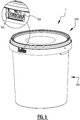
- Figure 1 shows an assembly 1 with a container 100 and closing means 200.
- the container 100 is a bucket and the closing means 200 is a lid.
- the assembly 1 comprises a tamper-evident seal 300.
- the container 100 includes a bottom 101 (not visible) and a circumferential wall 102. Along the open end of the container 100 a rim 103 is provided on the outside of the wall 102.
- the closing means include a main lid area 201 and peripheral wall 202.
- the peripheral wall 202 extends around the main lid area 201.
- FIG. 2A shows the assembly 1 with container 100, closing means 200 and tamper-evident seal 300 in more detail. From this figure it is clear that the tamper-evident seal 300 is connected to the container 100. The tamper-evident seal 300 is placed into a receiving space 104 of the rim 103 of the container 100, see also figure 5 wherein the receiving space 104 is clearly visible. The tamper-evident seal has an outer wall 302 in which a tab 305 has been formed. The outer wall 302 is arranged in the same circumferential plane as the rim 103, such that together they form a substantially continuous smooth outer rim surface.
- the tab 305 comprises a pulling section 307 that extends under an angle with respect to and thereby out of the plane of the remainder of the tab 305, such that the tab may be easily grasped using the pulling section 307..
- the tab 305 is connected to the outer wall 302 of the tamper-evident seal 300 via, in this example, two breakable connections 308 and a bendable and/or foldable connection 309.
- Figure 2B shows the same detail as figure 2A , however with the tamper-evident seal 300 broken.
- the tab 305 has been bended away from the closing means 200 and the container 100 over a small bending angle, but it is clear that the tab 307 may be bended further.
- the tamper-evident seal 300 can not be disconnected from the assembly 1 because it is blocked by the closing means 200.
- the closing means 200 can only be removed if the tamper-evident seal 300 has been broken by bending the tab 305. Consequently the tamper-evident seal 300 can only be disconnected from the assembly 1 if it has been broken.
- a user may attempt to remove the closing means 200 without breaking the seal 300, for example by using a knife or the like.
- the seal 300 will be broken for opening the container 100.
- FIG. 3 shows the free or lower edge 203 of peripheral wall 202 of the closing means. This free edge 203 extends between rim 103 and circumferential wall 102 when the closing means 200 closes the container 100 and is thereby not accessible or at least difficult to access.
- FIG 4 the same assembly 1 is shown with the closing means 200 removed from the container 100 and the tamper-evident seal 300 disconnected from the container 100.
- the removal of the tamper-evident seal 300 has exposed an indicator 199 that in this specific embodiment consists of the relief text 'NOT ORIGINAL'. It is thereby clearly visible for a user that the seal 300 is removed and that the content of the container 100 could have been tampered with.
- FIG. 5 is a detail of figure 4 .
- the receiving space 104 comprises two side zones 105, which side zones 105 extend perpendicular to the circumferential direction of the rim 103.
- the side zones 105 have been recessed with a slot 106 in which the tamper-evident seal 300 may be slid.
- the tamper-evident seal 300 has sliding means 306 that cooperate with slot 106.
- the sliding means in this example are elongated protrusions 306 extending from the side walls 303 of the tamper-evident seal 300.
- the protrusions 306 may be arranged in upper ends of the slots 106 and then the seal 300 can be moved downwards in a sliding movement until the seal 300 is completely accommodated in the receiving space 104.
- the receiving space 104 comprises a bottom zone 107 that extends between the side zones 105 in the longitudinal direction of the rim 103.
- the bottom zone 107 comprises a ridge 108 protrudes upwards in the direction of the open end of the container 100.
- the seal 300 comprises a hollow bottom or recess arranged therein for receiving the ridge 108.
- the seal 300 is thus connected to the container 100 with two sides 303 and the bottom thereof, thereby providing a strong connection.
- Figure 6 shows the assembly 1 with container 100 and closing means 200 without a tamper-evident seal 300 so that the indicator 199 is visible. This shows that even if the container 100 is again closed with the closing means 200 after opening the container 100, it is clearly visible that the container has been opened before. It is noted that the seal 300 may not need to be removed after breaking the seal. In that case it is visible that the tab has been bended, for example by the breakable connections 308 being broken and/or the fold connection 309 having been folded.
Landscapes
- Engineering & Computer Science (AREA)
- Mechanical Engineering (AREA)
- Closures For Containers (AREA)
Abstract
Description
- The invention relates in general to containers and corresponding closing means. More specifically the invention relates to an assembly comprising a container, closing means and a tamper-evident seal. Containers and corresponding closing means are available in a wide variety of embodiments applicable in many different types, such as buckets with lids and bottles with caps. Such containers may have a tamper-evident seal, which are also widely available and comprised in the state of the art.
- Tamper-evident seals are for example used to guarantee an end user that a product contained in the container is legitimate. Furthermore, tamper evident-evident seals may be used in for example the food industry to indicate that a packaging has been opened at least once, which may be important if a product has a limited shelf life after opening. Additionally, tamper-evident seals are used often in the food industry to certify that the edible product is safe to eat or drink and has not been tampered with for instance during transport.
- Tamper-evident seals may be arranged such that the container can not be opened, or at least can not be opened easily, without opening or breaking the seal. Furthermore, the tamper-evident seal can not be reclosed or mended, or at least not reclosed or mended without (visible) evidence thereof, so that the seal is an indication of whether or not the container has been opened. Such a tamper-evident seal often comprises at least one breakable part.
- It is an object of the invention to improve the assembly of the type described in the preamble.
- This object is achieved with an assembly comprising:
- a container comprising a bottom and a circumferential wall extending therefrom, and an opening;
- a closing means for closing said opening and a tamper-evident seal,
- wherein said tamper-evident seal is replaceably connectable as a separate element with one or both of the container and the closing means in order to replace a broken tamper-evident seal by an unbroken tamper-evident seal.
- A replaceably connectable tamper-evident seal has the advantage that a broken seal can be replaced by an unbroken tamper-evident seal. The same container and the same closing means can thus be reused with a new tamper-evident seal. Consequently, only the tamper-evident seal needs replacing. The tamper-evident seal may in particular be replaceable independently of the container and/or closing means. As only the tamper-evident seal constitutes to wastes, the invention may reduce waste and may be cheaper.
- The container and closing means may for example be reused after emptying the container. For example, empty containers may be collected by a manufacturer or supplier and may be refilled after cleaning the container. The refilled and closed containers may be provided with a new, unbroken tamper-evident seal, such that the refilled container can be used in the normal way with an indication of any tampering thereof. The replaceable tamper-evident seals may only be provided by the original manufacturer or supplier and may for example comprise evidence thereof, such that it can be guaranteed that the containers are refilled with the original product.
- The assembly may be configured so that it is not possible to open the container without breaking the tamper-evident seal.
- The tamper-evident seal may be provided at a contacting surface or contacting area between the container and the closing means.
- The container may be a bucket and the closing means may be a lid. Furthermore the container may be bottle and the closing means may be a cap. The container may also be another suitable type of container and the closing means may be any suitable corresponding closing means.
- The tamper-evident seal may prevent opening of the container, or at least may make opening of the container more difficult, and/or may prevent or hinder access to the closing means in an unbroken condition thereof, and may allow opening of the container and/or access to the closing means in a broken condition thereof. The tamper-evident seal may for example comprise a tab that can be pulled away by a user, such that after pulling the tab the user is able to grab the closing means and open the container.
- The bottom and a circumferential wall of the container may be integrally formed as one part.
- The bottom and circumferential wall of the container may have any suitable shape and/or size. For example, the bottom may be circular, oval, or polygonal. The circumferential wall may be adapted thereto and may in particular comprise a circular, oval, or polygonal end zone that is connected to the bottom. The other end zone of the wall away from the bottom of the container may have any suitable shape. The other end zone may define the opening of the container wherein the shape of the other end zone may be adapted to the shape of the closing means, or the other end zone may comprise a top side in which a closeable opening is arranged.
- In an embodiment according to the invention the tamper-evident seal comprises first connection means and one or both of the container and the closing means comprises second connecting means, wherein said first connecting means and said second connecting means are mutually cooperating.
- Providing a set of such mutually cooperating connection means may make it relatively easy for a user to replace the tamper-evident seal. Additionally or alternatively, such cooperating connection means may provide structural rigidity. Furthermore, cooperating connection means may for example make it impossible to access the product contained in the container without breaking the tamper-evident seal.
- If said container comprises said second connecting means the tamper-evident seal may be connected to the container using the first connecting means thereof. If said closing means comprises said second connecting means the tamper-evident seal may be connected to the closing means using the first connecting means thereof. If both said container and said closing means comprise said second connecting means the tamper-evident seal may be connected to both the container and the closing means using the first connecting means thereof.
- The first and second connecting means may be arranged in any suitable way. For example, the mutually cooperating connecting means may be arranged as a male and female connecting part, wherein the female connecting part is arranged for receiving the male connecting part.
- The first and second connecting means may in particular be arranged such that the tamper-evident seal may be connected to the container and/or closing means in a first direction and disconnected from the container and/or closing means in a second direction opposite to the first direction, wherein the seal is broken in a direction that is different and for example orthogonal to the first and/or second direction. This way the seal may be broken without disconnecting the seal.
- More in particular, one of said first connecting means and said second connecting means may comprise at least one recess and the other of said first connecting means and said second connecting means may comprise at least one protrusion, wherein said at least one recess is arranged to receive said at least one protrusion.
- The cooperating at least one recess and at least one protrusion provide a simple set of cooperating connection means, that may for example be easy to manufacture integrally with the container and/or closing means and the tamper-evident seal using for instance injection molding. Furthermore a combination of at least one recess and at least one protrusion may provide a connection that is of sufficient strength.
- Such an at least one recess may be provided at the tamper-evident seal, in which case the at least one protrusion may protrude from the container and/or the closing means. Alternatively the at least one recess may be provided at the container and/or the closing means, in which case the protrusion may protrude from the tamper-evident seal. Alternatively yet a combination of at least one protrusion and at least one recess may be provided at the tamper-evident seal, in which case at least one recess and at least one protrusion may be provided at the container and/or the closing means.
- The mutually cooperating recess and protrusion may be a hole and pin connection. The cross-sectional shapes of the hole and pin may be adapted to each other and may be any suitable shape, for example round or polygonal. Alternatively the mutually cooperating recess and protrusion may be a slot and one or more pins or an elongated protrusion.
- In yet another embodiment of the assemble according to the invention said recess has the shape of a slot in which said at least one protrusion is slideably connectable.
- A slot shaped recess constitutes a guide in which the at least one protrusion may be slid. A sliding motion may allow for easy and quick connection and disconnection in which the tamper-evident seal is connected and disconnected to the container and/or closing means in a translational movement. Additionally a sliding connection may provide rigidity in one ore more directions while allowing for said translational movement in at least one other direction. Said direction in which said sliding connection may be moved in translation may preferably be substantially orthogonal to the direction in which said tamper-evident seal may be broken and/or said direction in which said rigidity is provided may be parallel to the direction in which said tamper-evident seal may be broken. This way the tamper-evident seal is not disconnected during breaking of the seal.
- Such a slot shaped recess may be a groove. The protrusion may be an elongated protrusion, such as a ridge. The at least one protrusion may also be one or more pins and/or ridges.
- In yet another embodiment of the assembly according to the invention the assembly comprises an indicator for indicating whether the tamper-evident seal is present and/or missing and/or has been broken.
- The indicator may inform the end user quickly and/or clearly whether the seal is intact and/or in place and/or missing. Consequently the user may easily derive whether the container has been opened or not and the contents may have been tampered with.
- The indicator may for example be a visual indicator, such as text, a symbol, a bright color or a color different from the rest of the container and/or closing means and/or tamper-evident seal. The indicator may for example read 'NOT ORIGINAL', which may be visible when the tamper-evident seal is removed and/or broken. The indicator may consist of the tamper-evident seal being a color distinct from the container and/or the closing means, such that it is clearly visible that the tamper-evident is present. The indicator may also consist of a distinct color visible only when the tamper-evident seal is not present.
- Alternatively the indicator may be a tangible or palpable indicator. The indicator may comprise a symbol or text in relief.
- Additionally the indicator may be both visible and palpable.
- In yet another embodiment of the assembly according to the invention the tamper-evident seal comprises a tab that is movable from a first position in which the closing means can not be released to a second position in which the closing means can be released.
- A tab that is movable from such a first position to such a second position may provide a first 'locked' position and a second 'unlocked' position. The first 'locked' position may correspond to an unbroken seal, the second 'unlocked' position may correspond to a broken seal. It is preferably clearly visible for a user that the tab is in its second position, such that the user knows that the container could have been opened..
- Such a tamper-evident seal may for example block access to the closing means and/or the container when the tab is in the first position so that a user can not open the container. In the second position of the tab the closing means and/or the container may be accessible for opening the container.
- The tab may for example cover at least part of the closing means in it first position to render them inaccessible when the tab has not been moved to its second position, so that the tab has to be moved to its second position for opening the closing means.
- Alternatively or additionally such a tamper-evident seal may prevent relative motion between the closing means and the container when the tab is in the first position so that the container can not be opened and the contents can not be accessed. Such a tamper-evident seal may allow relative motion between the closing means and the container when the tab is in the second position so that the container can be opened and the contents can be accessed.
- The tab may for example be foldable from its first to its second position.Moving the tab from the first position to the second position may require some or even considerable, manual force, such that the chance that the tab is moved to the second position by accident is small.
- In yet another embodiment of the assembly according to the invention said tab is connected to said tamper-evident seal via a breakable connection, a click connection, a snap connection or the like.
- In such an embodiment moving the tab from the first position to the second position may require overcoming counteractive measures, for example by breaking the breakable connection, or opening the click or snap connection. Moving the tab from the second position to the first position once the tab has been moved to the second position may be difficult or even impossible. Such reverse movement may for example be impossible due to said breakable connection being broken or said click or snap connection working only one-way.
- If the tab can be moved back from the second position to the first position t is preferably visible that the tab has been moved back from the second position to its first position and thereby that the container could have been opened.
- In the second position the tab may extend out of a main plain of the tamper-evident seal. Thereby it is clearly visible that the tab is moved to its second position and that the closing means could have been opened.
- In yet another embodiment according to the invention the tamper-evident seal comprises a removable tab, wherein said closing means can be released when said tab has been removed.
- A tamper-evident seal with a removable tab has the advantage that it is clearly visible when the seal has been broken because the removable tab is missing.
- The removable tab may for example cover at least part of the closing means to render them inaccessible when the tab has not been removed, so that the tab has to be removed for opening the closing means. The tab may for example be connected to the tamper-evident seal using a weakened connection portion or a perforated connection portion, such that the tab may be easily broken of via said weakened or perforated portion.
- The container may in particular be a bucket and the closing means may in particular be a lid.
- The bucket may comprise a bottom wall that may be circular in shape. The circumferential wall may be annular and disposed at a near 90 degree angle with respect to the bottom wall. The circumferential wall may also have the shape of a hollow cone with its apex cut off, extending outwards either towards or away from the bottom wall.
- The lid may comprise a main lid surface that is of circular shape. The main lid surface may substantially be of the same dimension as or somewhat larger than the free edge of the circumferential wall so that the main lid surface is configured to cover and close the bucket.
- The lid may a comprise a peripheral wall disposed along the edge of the main lid surface substantially perpendicular thereto, i.e. substantially parallel to the circumferential wall of the lid when the lid is connected thereto .
- As described above, the bottom of the container and the closing means do not necessarily have to be of circular shape but may be of other shapes such as of triangular, rectangular or of other shapes.
- In yet another embodiment of the assembly according to the invention the container comprises a rim with a receiving space for receiving said tamper-evident seal.
- An additional rim provides the advantage that the circumferential wall can be used to contain a product whilst the rim can be configured to contain the tamper-evident seal in said receiving space thereof. The rim may provide structural rigidity. The receiving space may be arranged, in particular have a shape and/or size, such that it can accommodate the tamper-evident seal completely or almost completely so that the container has a smooth contour, which is advantageous for storage and transport.
- The rim may run along the open end of the container on the outside of the circumferential wall.
- The rim and the circumferential wall may provide an annular space in between them.
- The assembly may be arranged such that a part of the closing means, for example a or the peripheral wall thereof, can be placed at least partly between the circumferential wall and the rim of the container in the annular space. The rim may thereby prevent or at least hinder access to the closing means and thereby prevent or at least hinder opening the closing means. By breaking the tamper-evident seal, for example by moving the tab to its second position or by removing the tab, said part of the closing means, for example said peripheral wall, may be at least partly exposed and thereby accessible for opening the container.
- In yet another embodiment according to the invention an edge zone of said receiving space comprises one of the first connecting means and the second connecting means.
- The edge zone may for example comprise one or both side zones of the receiving space, wherein the side zones are defined parallel to the circumferential wall of the container, i.e. orthogonal to the circumferential direction of the rim. Providing said first or second connecting means to both side zones of the receiving space may in particular provide a strong connection between the tamper-evident seal and the container.
- For example, said one or both side zones may comprise elongated recesses or protrusions which extend over substantially the entire length of said one or both side zones, such that said tamper-evident seal may be slideably connected to the receiving space and whereby a relatively strong connection is provided.
- The invention also relates to a tamper-evident seal for use in an assembly as described in any of the embodiments described above, said tamper-evident seal being a separate element that is connectable with one or both of the container and the closing means.
- Such a tamper-evident seal may be used to seal the container with the closing means. The tamper-evident seal may provide a user with an indication whether container has been opened.
- Opening the container may require breaking the tamper-evident seal. After use the container and closing means can be reused, for example by cleaning and refilling the container. The broken tamper-evident seal may be replaced by a new, unbroken tamper-evident seal.
- The tamper-evident seal may comprise first connection means, configured to cooperate with second connecting means that may be comprised in a container and/or closing means.
- Said first connection means of the tamper-evident seal may comprise at least one recess and/or at least one protrusion. In this case said second connection means may comprise the other of the at least one recess and/or at least one protrusion. The at least one recess and/or at least one protrusion of the first connection means of the tamper-evident seal may be configured to cooperate with the other one of the at least one protrusion and/or at least one recess of the second connection means.
- Said at least one recess of said first connection means and/or second connection means of the tamper-evident seal may have the shape of a slot, wherein the at least one protrusion of the second connection means of the tamper-evident seal is slideably connectable.
- The tamper-evident seal may comprise an indicator for indicating whether the tamper-evident seal is present and/or missing and/or has been broken.
- The tamper-evident seal may comprise a tab that is movable form a first position in which the closing means can not be released to a second position in which the closing means can be released.
- The tamper-evident seal may comprise a removable tab, wherein said closing means can be released when said tab has been removed.
- Said tamper-evident seal may comprise any feature as described with respect to the assembly above, in any suitable combination.
- The invention also relates to a container for use in an assembly as described in any of the embodiments described above, said container comprising second connecting means for connecting with first connecting means of a said tamper-evident seal.
- Such a container can be arranged for connecting a replaceable tamper-evident seal thereto. The container may be reused, while only the tamper-evident seal may need to be replaced.
- Said container may comprise any feature as described with respect to the assembly above, in any suitable combination.
- The invention also relates to a closing means for use in an assembly as described in any of the embodiments described above, said closing means comprising second connecting means for connecting with first connecting means of a said tamper-evident means.
- Such a closing means can be arranged for connecting a replaceable tamper-evident seal thereto. The closing means may be reused, while only the tamper-evident seal may need to be replaced.
- Said closing means may comprise any feature as described with respect to the assembly above, in any suitable combination.
- Furthermore the invention relates to a method of filling or refilling a container, said method comprising the steps, to be performed in any suitable order, of: providing a said container of an assembly described above, filling or refilling said container, closing said container with a closing means described above, characterized by connecting a tamper evident seal as described above with one or both of the container and the closing means.
- The method provides the advantage that said container and closing means may be reused by refilling the container, wherein the tamper-evident seal may be replaced by a new, unbroken seal after refilling thereby providing proof that the container is correctly refilled, for example by the original manufacturer or supplier.
- The steps may be performed in any suitable order. Practically, step b) may be performed before step c). Step d) may for example be performed at any moment, for example before or after step a, before or after step b), or before or after step c).
- Such method may include providing the filled, closed and sealed container to a user. The user may break the seal upon opening the container. The container and the closing means may be collected for reuse thereof. The user may throw away the broken tamper-evident seal. Alternatively the user may return the broken tamper-evident seal as a token. The token may be used to certify that the user has used a legitimate product.
- Said method may further comprise the further step of cleaning the container, to be performed before step b).
- Said method may further comprise the further step of cleaning the closing means, to be performed before step c).
- Throughout this application breaking the seal should not be interpreted as being limited to breaking off the seal or part of the seal. The seal or part of the seal may be broken off, but may also be broken without breaking off the seal or part thereof.
- The invention will be further elucidated with respect to the following figures showing embodiments for example and not limitation. Herein:
-
Figure 1 shows an assembly according to the invention in a schematic perspective view; -
Figures 2A and 2B are a detailed perspective view of the tamper-evident seal with an unbroken and broken seal, respectively =; -
Figure 3 is a perspective view of the assembly with the closing means opened; -
Figure 4 is a perspective view of the assembly with the closing means opened and the tamper-evident seal removed; -
Figure 5 is a detail offigure 4 ; -
Figure 6 shows the assembly without the tamper-evident seal. - In the following, like numbers represent like features.
-
Figure 1 shows anassembly 1 with acontainer 100 and closing means 200. In this example thecontainer 100 is a bucket and the closing means 200 is a lid. Theassembly 1 comprises a tamper-evident seal 300. - The
container 100 includes a bottom 101 (not visible) and acircumferential wall 102. Along the open end of the container 100 arim 103 is provided on the outside of thewall 102. The closing means include amain lid area 201 andperipheral wall 202. Theperipheral wall 202 extends around themain lid area 201. -
Figure 2A shows theassembly 1 withcontainer 100, closing means 200 and tamper-evident seal 300 in more detail. From this figure it is clear that the tamper-evident seal 300 is connected to thecontainer 100. The tamper-evident seal 300 is placed into a receivingspace 104 of therim 103 of thecontainer 100, see alsofigure 5 wherein the receivingspace 104 is clearly visible. The tamper-evident seal has anouter wall 302 in which atab 305 has been formed. Theouter wall 302 is arranged in the same circumferential plane as therim 103, such that together they form a substantially continuous smooth outer rim surface. In this example thetab 305 comprises a pullingsection 307 that extends under an angle with respect to and thereby out of the plane of the remainder of thetab 305, such that the tab may be easily grasped using the pullingsection 307.. Thetab 305 is connected to theouter wall 302 of the tamper-evident seal 300 via, in this example, twobreakable connections 308 and a bendable and/orfoldable connection 309. -
Figure 2B shows the same detail asfigure 2A , however with the tamper-evident seal 300 broken. In this example this means that thebreakable connections 308 have been broken and the bendable and/orfoldable connection 309 has been bend. Infigure 2B thetab 305 has been bended away from the closing means 200 and thecontainer 100 over a small bending angle, but it is clear that thetab 307 may be bended further. After breaking theseal 300 by folding thetab 307 out of the plane of the outer wall 302the lower edge of theperipheral wall 202 of the closing means 200 is accessible to a user that may now open the container by grasping theperipheral wall 202 and pulling of the closing means 200 from thecontainer 100. - In this example embodiment the tamper-
evident seal 300 can not be disconnected from theassembly 1 because it is blocked by the closing means 200. The closing means 200 can only be removed if the tamper-evident seal 300 has been broken by bending thetab 305. Consequently the tamper-evident seal 300 can only be disconnected from theassembly 1 if it has been broken. - It is noted that a user may attempt to remove the closing means 200 without breaking the
seal 300, for example by using a knife or the like. However, in a normal and/or easy use of the assembly according to the invention theseal 300 will be broken for opening thecontainer 100. - As described briefly above, after the tamper-
evident seal 300 has been broken the closing means 200 may be lifted and in particular removed to open thecontainer 100 as is shown inFigure 3 . Opening thecontainer 100 exposes itsinner product space 150 so that a product contained therein may be accessed.Figure 3 shows the free orlower edge 203 ofperipheral wall 202 of the closing means. Thisfree edge 203 extends betweenrim 103 andcircumferential wall 102 when the closing means 200 closes thecontainer 100 and is thereby not accessible or at least difficult to access. After breaking theseal 300 by bending thetab 305 thefree edge 203 of the closing means 200 is exposed in the area where the tab has been bended away, such that after breaking theseal 300 the closing means 200 can be removed from the container. - In
Figure 4 thesame assembly 1 is shown with the closing means 200 removed from thecontainer 100 and the tamper-evident seal 300 disconnected from thecontainer 100. The removal of the tamper-evident seal 300 has exposed anindicator 199 that in this specific embodiment consists of the relief text 'NOT ORIGINAL'. It is thereby clearly visible for a user that theseal 300 is removed and that the content of thecontainer 100 could have been tampered with. -
Figure 5 is a detail offigure 4 .. From this figure it is clear that thecontainer 100 has in its rim 103 a receivingspace 104 in which a tamper-evident seal 300 may be placed. The receivingspace 104 comprises twoside zones 105, whichside zones 105 extend perpendicular to the circumferential direction of therim 103. Theside zones 105 have been recessed with aslot 106 in which the tamper-evident seal 300 may be slid. For this purpose the tamper-evident seal 300 has slidingmeans 306 that cooperate withslot 106. The sliding means in this example are elongatedprotrusions 306 extending from theside walls 303 of the tamper-evident seal 300. Theprotrusions 306 may be arranged in upper ends of theslots 106 and then theseal 300 can be moved downwards in a sliding movement until theseal 300 is completely accommodated in the receivingspace 104. - Additionally the receiving
space 104 comprises abottom zone 107 that extends between theside zones 105 in the longitudinal direction of therim 103. Thebottom zone 107 comprises aridge 108 protrudes upwards in the direction of the open end of thecontainer 100. Theseal 300 comprises a hollow bottom or recess arranged therein for receiving theridge 108. - The
seal 300 is thus connected to thecontainer 100 with twosides 303 and the bottom thereof, thereby providing a strong connection. -
Figure 6 shows theassembly 1 withcontainer 100 and closing means 200 without a tamper-evident seal 300 so that theindicator 199 is visible. This shows that even if thecontainer 100 is again closed with the closing means 200 after opening thecontainer 100, it is clearly visible that the container has been opened before. It is noted that theseal 300 may not need to be removed after breaking the seal. In that case it is visible that the tab has been bended, for example by thebreakable connections 308 being broken and/or thefold connection 309 having been folded. - It is noted that the invention is not limited to the shown embodiments but also extends to variants within the scope of the appended claims.
Claims (14)
- Assembly comprising:- a container comprising a bottom and a circumferential wall extending therefrom, and an opening;- closing means for closing said opening;- a tamper-evident seal;characterized in that said tamper-evident seal is replaceably connectable as a separate element with one or both of the container and the closing means in order to replace a broken tamper-evident seal by an unbroken tamper-evident seal.
- Assembly according to claim 1, wherein the tamper-evident seal comprises first connection means and one or both of the container and the closing means comprises second connecting means, wherein said first connecting means and said second connecting means are mutually cooperating.
- Assembly according to claim 2, wherein one of said first connecting means and said second connecting means comprises at least one recess and wherein the other of said first connecting means and said second connecting means comprises at least one protrusion, wherein said at least one recess is arranged to receive said at least one protrusion.
- Assembly according to claim 3, wherein said at least one recess has the shape of a slot in which said at least one protrusion is slideably connectable.
- Assembly according to any of the preceding claims, comprising an indicator for indicating whether the tamper-evident seal is present and/or missing and/or has been broken.
- Assembly according to any of the preceding claims, wherein the tamper-evident seal comprises a tab that is movable from a first position in which the closing means can not be released to a second position in which the closing means can be released.
- Assembly according to any of the preceding claims 1 - 5, wherein the tamper-evident seal comprises a removable tab, wherein said closing means can be released when said tab has been removed.
- Assembly according to any of the preceding claims, wherein the container is a bucket and the closing means is a lid.
- Assembly according to any of the preceding claims, wherein the container comprises a rim with a receiving space for receiving said tamper-evident seal.
- Assembly according to claim 9 as dependent on claim 2, wherein an edge zone of said receiving space comprises one of the first connecting means and the second connecting means.
- Tamper-evident seal for use in an assembly according to any of claims 1 - 10, said tamper-evident seal being a separate element that is connectable with one or both of the container and the closing means.
- Container for use in an assembly according to any of claims 2 - 10, said container comprising second connecting means for connecting with first connecting means of a said tamper-evident seal.
- Closing means for use in an assembly according to any of claims 2 - 10, said closing means comprising second connecting means for connecting with first connecting means of a said tamper-evident seal.
- Method for filling or refilling a container, said method comprising the steps, to be performed in any suitable order, of:a) providing a said container of an assembly according to any of claims 1 - 10 or according to claim 13;b) filling or refilling said container;c) closing said container with a closing means of an assembly according to any of claims 1 - 10 or according to claim 14;characterized byd) connecting a tamper-evident seal of an assembly according to any of claims 1 - 10 or according to claim 12 with one or both of the container and the closing means.
Priority Applications (1)
| Application Number | Priority Date | Filing Date | Title |
|---|---|---|---|
| EP17155781.2A EP3360816B1 (en) | 2017-02-13 | 2017-02-13 | Assembly with replaceable tamper-evident seal, replaceable tamper-evident seal and method for using such an assembly |
Applications Claiming Priority (1)
| Application Number | Priority Date | Filing Date | Title |
|---|---|---|---|
| EP17155781.2A EP3360816B1 (en) | 2017-02-13 | 2017-02-13 | Assembly with replaceable tamper-evident seal, replaceable tamper-evident seal and method for using such an assembly |
Publications (3)
| Publication Number | Publication Date |
|---|---|
| EP3360816A1 true EP3360816A1 (en) | 2018-08-15 |
| EP3360816B1 EP3360816B1 (en) | 2023-08-09 |
| EP3360816C0 EP3360816C0 (en) | 2023-08-09 |
Family
ID=58017986
Family Applications (1)
| Application Number | Title | Priority Date | Filing Date |
|---|---|---|---|
| EP17155781.2A Active EP3360816B1 (en) | 2017-02-13 | 2017-02-13 | Assembly with replaceable tamper-evident seal, replaceable tamper-evident seal and method for using such an assembly |
Country Status (1)
| Country | Link |
|---|---|
| EP (1) | EP3360816B1 (en) |
Citations (3)
| Publication number | Priority date | Publication date | Assignee | Title |
|---|---|---|---|---|
| US5238134A (en) * | 1992-08-20 | 1993-08-24 | The United States Of America As Represented By The Director Of The National Security Agency | Limited-reuse tamper-evident container |
| US5893475A (en) * | 1997-04-16 | 1999-04-13 | Sprintquip Nz Limited | Tamper proof container |
| WO2013158062A2 (en) * | 2012-04-16 | 2013-10-24 | University Of Manitoba | Reusable electronic seal |
Family Cites Families (3)
| Publication number | Priority date | Publication date | Assignee | Title |
|---|---|---|---|---|
| CA2028225C (en) * | 1990-10-22 | 1996-08-06 | Garry D. Flaherty | Tamper resistant containers |
| AR056770A1 (en) * | 2005-11-15 | 2007-10-24 | Bayer Consumer Care Ag | WARRANTY CLOSURE |
| US8146766B2 (en) * | 2009-04-29 | 2012-04-03 | Pwp Industries | Enhanced secure container |
-
2017
- 2017-02-13 EP EP17155781.2A patent/EP3360816B1/en active Active
Patent Citations (3)
| Publication number | Priority date | Publication date | Assignee | Title |
|---|---|---|---|---|
| US5238134A (en) * | 1992-08-20 | 1993-08-24 | The United States Of America As Represented By The Director Of The National Security Agency | Limited-reuse tamper-evident container |
| US5893475A (en) * | 1997-04-16 | 1999-04-13 | Sprintquip Nz Limited | Tamper proof container |
| WO2013158062A2 (en) * | 2012-04-16 | 2013-10-24 | University Of Manitoba | Reusable electronic seal |
Also Published As
| Publication number | Publication date |
|---|---|
| EP3360816B1 (en) | 2023-08-09 |
| EP3360816C0 (en) | 2023-08-09 |
Similar Documents
| Publication | Publication Date | Title |
|---|---|---|
| EP2576376B1 (en) | Reclosable container | |
| US7222741B2 (en) | Tamper evident cap | |
| KR101244109B1 (en) | Tamper-indicating dispensing closure | |
| US7931167B2 (en) | Tamper evident cap for shipping and storage containers | |
| US6877631B1 (en) | Tamper-evident container | |
| US11780654B2 (en) | Container with tearable lid | |
| PL203136B1 (en) | Container closure system | |
| US9994369B2 (en) | Tamper evident and resistant container | |
| HU225732B1 (en) | Reclosable pouring element and a flat gable composite packaging provided therewith | |
| EP3064446B1 (en) | Tamper evident container | |
| US9061812B1 (en) | Tamper-evident locking container | |
| JP5449960B2 (en) | Hinge cap with tamper-evident mechanism | |
| US9156595B2 (en) | Tamper evident lid and container | |
| US10435210B1 (en) | Scoop dock and use methods | |
| CN115052815A (en) | Sealing cover | |
| EP3360816B1 (en) | Assembly with replaceable tamper-evident seal, replaceable tamper-evident seal and method for using such an assembly | |
| US11628981B2 (en) | Tamper evident container | |
| KR200425505Y1 (en) | Safety cap for packing container | |
| CN110234575B (en) | Liquid-tight and tamper-proof barrel arrangement | |
| EP4710032A1 (en) | Cap for providing a tamper evidence feature | |
| JP2010235167A (en) | Cap | |
| JP2014129104A (en) | Cap and cap-provided container | |
| RU235561U1 (en) | CAPPER FOR CONTAINER | |
| JP4803661B2 (en) | Tamper-evident hinge cap | |
| JP3012002U (en) | Containers and canopies for containers |
Legal Events
| Date | Code | Title | Description |
|---|---|---|---|
| PUAI | Public reference made under article 153(3) epc to a published international application that has entered the european phase |
Free format text: ORIGINAL CODE: 0009012 |
|
| STAA | Information on the status of an ep patent application or granted ep patent |
Free format text: STATUS: THE APPLICATION HAS BEEN PUBLISHED |
|
| AK | Designated contracting states |
Kind code of ref document: A1 Designated state(s): AL AT BE BG CH CY CZ DE DK EE ES FI FR GB GR HR HU IE IS IT LI LT LU LV MC MK MT NL NO PL PT RO RS SE SI SK SM TR |
|
| AX | Request for extension of the european patent |
Extension state: BA ME |
|
| STAA | Information on the status of an ep patent application or granted ep patent |
Free format text: STATUS: REQUEST FOR EXAMINATION WAS MADE |
|
| 17P | Request for examination filed |
Effective date: 20190214 |
|
| RBV | Designated contracting states (corrected) |
Designated state(s): AL AT BE BG CH CY CZ DE DK EE ES FI FR GB GR HR HU IE IS IT LI LT LU LV MC MK MT NL NO PL PT RO RS SE SI SK SM TR |
|
| STAA | Information on the status of an ep patent application or granted ep patent |
Free format text: STATUS: EXAMINATION IS IN PROGRESS |
|
| 17Q | First examination report despatched |
Effective date: 20200402 |
|
| GRAP | Despatch of communication of intention to grant a patent |
Free format text: ORIGINAL CODE: EPIDOSNIGR1 |
|
| STAA | Information on the status of an ep patent application or granted ep patent |
Free format text: STATUS: GRANT OF PATENT IS INTENDED |
|
| INTG | Intention to grant announced |
Effective date: 20230324 |
|
| GRAS | Grant fee paid |
Free format text: ORIGINAL CODE: EPIDOSNIGR3 |
|
| GRAA | (expected) grant |
Free format text: ORIGINAL CODE: 0009210 |
|
| STAA | Information on the status of an ep patent application or granted ep patent |
Free format text: STATUS: THE PATENT HAS BEEN GRANTED |
|
| AK | Designated contracting states |
Kind code of ref document: B1 Designated state(s): AL AT BE BG CH CY CZ DE DK EE ES FI FR GB GR HR HU IE IS IT LI LT LU LV MC MK MT NL NO PL PT RO RS SE SI SK SM TR |
|
| REG | Reference to a national code |
Ref country code: GB Ref legal event code: FG4D |
|
| REG | Reference to a national code |
Ref country code: CH Ref legal event code: EP |
|
| REG | Reference to a national code |
Ref country code: DE Ref legal event code: R096 Ref document number: 602017072384 Country of ref document: DE |
|
| REG | Reference to a national code |
Ref country code: IE Ref legal event code: FG4D |
|
| U01 | Request for unitary effect filed |
Effective date: 20230907 |
|
| U07 | Unitary effect registered |
Designated state(s): AT BE BG DE DK EE FI FR IT LT LU LV MT NL PT SE SI Effective date: 20230914 |
|
| PG25 | Lapsed in a contracting state [announced via postgrant information from national office to epo] |
Ref country code: GR Free format text: LAPSE BECAUSE OF FAILURE TO SUBMIT A TRANSLATION OF THE DESCRIPTION OR TO PAY THE FEE WITHIN THE PRESCRIBED TIME-LIMIT Effective date: 20231110 |
|
| PG25 | Lapsed in a contracting state [announced via postgrant information from national office to epo] |
Ref country code: IS Free format text: LAPSE BECAUSE OF FAILURE TO SUBMIT A TRANSLATION OF THE DESCRIPTION OR TO PAY THE FEE WITHIN THE PRESCRIBED TIME-LIMIT Effective date: 20231209 |
|
| PG25 | Lapsed in a contracting state [announced via postgrant information from national office to epo] |
Ref country code: RS Free format text: LAPSE BECAUSE OF FAILURE TO SUBMIT A TRANSLATION OF THE DESCRIPTION OR TO PAY THE FEE WITHIN THE PRESCRIBED TIME-LIMIT Effective date: 20230809 Ref country code: NO Free format text: LAPSE BECAUSE OF FAILURE TO SUBMIT A TRANSLATION OF THE DESCRIPTION OR TO PAY THE FEE WITHIN THE PRESCRIBED TIME-LIMIT Effective date: 20231109 Ref country code: IS Free format text: LAPSE BECAUSE OF FAILURE TO SUBMIT A TRANSLATION OF THE DESCRIPTION OR TO PAY THE FEE WITHIN THE PRESCRIBED TIME-LIMIT Effective date: 20231209 Ref country code: HR Free format text: LAPSE BECAUSE OF FAILURE TO SUBMIT A TRANSLATION OF THE DESCRIPTION OR TO PAY THE FEE WITHIN THE PRESCRIBED TIME-LIMIT Effective date: 20230809 Ref country code: GR Free format text: LAPSE BECAUSE OF FAILURE TO SUBMIT A TRANSLATION OF THE DESCRIPTION OR TO PAY THE FEE WITHIN THE PRESCRIBED TIME-LIMIT Effective date: 20231110 |
|
| PG25 | Lapsed in a contracting state [announced via postgrant information from national office to epo] |
Ref country code: PL Free format text: LAPSE BECAUSE OF FAILURE TO SUBMIT A TRANSLATION OF THE DESCRIPTION OR TO PAY THE FEE WITHIN THE PRESCRIBED TIME-LIMIT Effective date: 20230809 |
|
| U20 | Renewal fee for the european patent with unitary effect paid |
Year of fee payment: 8 Effective date: 20240227 |
|
| PG25 | Lapsed in a contracting state [announced via postgrant information from national office to epo] |
Ref country code: ES Free format text: LAPSE BECAUSE OF FAILURE TO SUBMIT A TRANSLATION OF THE DESCRIPTION OR TO PAY THE FEE WITHIN THE PRESCRIBED TIME-LIMIT Effective date: 20230809 |
|
| PG25 | Lapsed in a contracting state [announced via postgrant information from national office to epo] |
Ref country code: SM Free format text: LAPSE BECAUSE OF FAILURE TO SUBMIT A TRANSLATION OF THE DESCRIPTION OR TO PAY THE FEE WITHIN THE PRESCRIBED TIME-LIMIT Effective date: 20230809 Ref country code: RO Free format text: LAPSE BECAUSE OF FAILURE TO SUBMIT A TRANSLATION OF THE DESCRIPTION OR TO PAY THE FEE WITHIN THE PRESCRIBED TIME-LIMIT Effective date: 20230809 Ref country code: ES Free format text: LAPSE BECAUSE OF FAILURE TO SUBMIT A TRANSLATION OF THE DESCRIPTION OR TO PAY THE FEE WITHIN THE PRESCRIBED TIME-LIMIT Effective date: 20230809 Ref country code: CZ Free format text: LAPSE BECAUSE OF FAILURE TO SUBMIT A TRANSLATION OF THE DESCRIPTION OR TO PAY THE FEE WITHIN THE PRESCRIBED TIME-LIMIT Effective date: 20230809 Ref country code: SK Free format text: LAPSE BECAUSE OF FAILURE TO SUBMIT A TRANSLATION OF THE DESCRIPTION OR TO PAY THE FEE WITHIN THE PRESCRIBED TIME-LIMIT Effective date: 20230809 |
|
| REG | Reference to a national code |
Ref country code: DE Ref legal event code: R097 Ref document number: 602017072384 Country of ref document: DE |
|
| PLBE | No opposition filed within time limit |
Free format text: ORIGINAL CODE: 0009261 |
|
| STAA | Information on the status of an ep patent application or granted ep patent |
Free format text: STATUS: NO OPPOSITION FILED WITHIN TIME LIMIT |
|
| 26N | No opposition filed |
Effective date: 20240513 |
|
| PG25 | Lapsed in a contracting state [announced via postgrant information from national office to epo] |
Ref country code: MC Free format text: LAPSE BECAUSE OF FAILURE TO SUBMIT A TRANSLATION OF THE DESCRIPTION OR TO PAY THE FEE WITHIN THE PRESCRIBED TIME-LIMIT Effective date: 20230809 |
|
| REG | Reference to a national code |
Ref country code: CH Ref legal event code: PL |
|
| PG25 | Lapsed in a contracting state [announced via postgrant information from national office to epo] |
Ref country code: CH Free format text: LAPSE BECAUSE OF NON-PAYMENT OF DUE FEES Effective date: 20240229 |
|
| PG25 | Lapsed in a contracting state [announced via postgrant information from national office to epo] |
Ref country code: CH Free format text: LAPSE BECAUSE OF NON-PAYMENT OF DUE FEES Effective date: 20240229 |
|
| U20 | Renewal fee for the european patent with unitary effect paid |
Year of fee payment: 9 Effective date: 20250227 |
|
| PG25 | Lapsed in a contracting state [announced via postgrant information from national office to epo] |
Ref country code: CY Free format text: LAPSE BECAUSE OF FAILURE TO SUBMIT A TRANSLATION OF THE DESCRIPTION OR TO PAY THE FEE WITHIN THE PRESCRIBED TIME-LIMIT; INVALID AB INITIO Effective date: 20170213 |
|
| PG25 | Lapsed in a contracting state [announced via postgrant information from national office to epo] |
Ref country code: HU Free format text: LAPSE BECAUSE OF FAILURE TO SUBMIT A TRANSLATION OF THE DESCRIPTION OR TO PAY THE FEE WITHIN THE PRESCRIBED TIME-LIMIT; INVALID AB INITIO Effective date: 20170213 |
|
| PG25 | Lapsed in a contracting state [announced via postgrant information from national office to epo] |
Ref country code: TR Free format text: LAPSE BECAUSE OF FAILURE TO SUBMIT A TRANSLATION OF THE DESCRIPTION OR TO PAY THE FEE WITHIN THE PRESCRIBED TIME-LIMIT Effective date: 20230809 |
|
| U20 | Renewal fee for the european patent with unitary effect paid |
Year of fee payment: 10 Effective date: 20260227 |
|
| PGFP | Annual fee paid to national office [announced via postgrant information from national office to epo] |
Ref country code: GB Payment date: 20260227 Year of fee payment: 10 |
|
| PGFP | Annual fee paid to national office [announced via postgrant information from national office to epo] |
Ref country code: IE Payment date: 20260227 Year of fee payment: 10 |