EP3360815A1 - Child-resistant reclosable bags - Google Patents
Child-resistant reclosable bags Download PDFInfo
- Publication number
- EP3360815A1 EP3360815A1 EP18154988.2A EP18154988A EP3360815A1 EP 3360815 A1 EP3360815 A1 EP 3360815A1 EP 18154988 A EP18154988 A EP 18154988A EP 3360815 A1 EP3360815 A1 EP 3360815A1
- Authority
- EP
- European Patent Office
- Prior art keywords
- bag
- wall
- flange
- container
- zipper
- Prior art date
- Legal status (The legal status is an assumption and is not a legal conclusion. Google has not performed a legal analysis and makes no representation as to the accuracy of the status listed.)
- Granted
Links
Images









Classifications
-
- B—PERFORMING OPERATIONS; TRANSPORTING
- B65—CONVEYING; PACKING; STORING; HANDLING THIN OR FILAMENTARY MATERIAL
- B65D—CONTAINERS FOR STORAGE OR TRANSPORT OF ARTICLES OR MATERIALS, e.g. BAGS, BARRELS, BOTTLES, BOXES, CANS, CARTONS, CRATES, DRUMS, JARS, TANKS, HOPPERS, FORWARDING CONTAINERS; ACCESSORIES, CLOSURES, OR FITTINGS THEREFOR; PACKAGING ELEMENTS; PACKAGES
- B65D33/00—Details of, or accessories for, sacks or bags
- B65D33/16—End- or aperture-closing arrangements or devices
- B65D33/25—Riveting; Dovetailing; Screwing; using press buttons or slide fasteners
- B65D33/2508—Riveting; Dovetailing; Screwing; using press buttons or slide fasteners using slide fasteners with interlocking members having a substantially uniform section throughout the length of the fastener; Sliders therefor
- B65D33/2541—Riveting; Dovetailing; Screwing; using press buttons or slide fasteners using slide fasteners with interlocking members having a substantially uniform section throughout the length of the fastener; Sliders therefor characterised by the slide fastener, e.g. adapted to interlock with a sheet between the interlocking members having sections of particular shape
-
- B—PERFORMING OPERATIONS; TRANSPORTING
- B65—CONVEYING; PACKING; STORING; HANDLING THIN OR FILAMENTARY MATERIAL
- B65D—CONTAINERS FOR STORAGE OR TRANSPORT OF ARTICLES OR MATERIALS, e.g. BAGS, BARRELS, BOTTLES, BOXES, CANS, CARTONS, CRATES, DRUMS, JARS, TANKS, HOPPERS, FORWARDING CONTAINERS; ACCESSORIES, CLOSURES, OR FITTINGS THEREFOR; PACKAGING ELEMENTS; PACKAGES
- B65D2215/00—Child-proof means
- B65D2215/08—Child-proof means for fooling children, e.g. fake closures
Definitions
- the present disclosure relates to various embodiments of child-resistant reclosable packages or bags.
- the prior art includes various child-resistant packages. Typically, these packages are designed to hold medicinal capsules, detergent capsules, or similar items which might be attractive, but harmful, to a child.
- the prior art has many examples of plastic lids, in order to be removed from the glass or plastic container, which must be squeezed or pushed in various ways which would not be apparent to a child or would be beyond the strength capabilities of the child.
- plastic lids in order to be removed from the glass or plastic container, which must be squeezed or pushed in various ways which would not be apparent to a child or would be beyond the strength capabilities of the child.
- such containers are complicated to manufacture and add a considerable expense to the consumer product. Additionally, such containers may be heavy and bulky which adds to the costs of transportation. Furthermore, this weight and bulk adds to the recycling burden of these products.
- a polymeric or plastic container with various zipper configurations including zipper configurations with a high internal opening force and a low external opening force.
- Such configurations include zippers where only three flanges are sealed, so if the child attempts to open the bag by pulling the external part of the bag, the high opening force of the zipper is encountered. In order to encounter the low external opening force, the user must grab the unsealed external flange while attempting to open the bag.
- zipper, reclosure or closure 10 includes first and second profiles 12, 14.
- First profile 12 includes a first exterior flange 16 and a first interior flange 18 as well as a female interlocking element 20 formed from first and second upwardly extending arms 22, 24 terminating in respective first and second detent hooks 26, 28.
- second profile 14 includes second exterior flange 32 and a second interior flange 34 as well as a male interlocking element 36 formed from a post 38 and an arrowhead element 40.
- the interior wing 42 of arrowhead element 40 is more enlarged and protruding than the exterior wing 44 of arrowhead element 40. This causes the interior or product side or inside opening force to be greater than the exterior or consumer side or outside opening force.
- First and second profiles 12, 14 are sealed or otherwise attached to the respective first and second sidewalls 102, 104 of bag 100.
- sidewalls 102, 104 are joined or integral so as to form a storage volume 106 in the interior of the bag 100.
- First exterior flange 16 and first interior flange 18 are sealed to first sidewall 102 so that the first exterior flange 16 is oriented toward the consumer side of the zipper and the first interior flange 18 is oriented toward the product side of the zipper.
- second interior flange 34 is sealed to second sidewall 104 so that the second exterior flange 32 (with a horizontal upper edge 33) is oriented toward the consumer side of the zipper and the second interior flange 34 is oriented toward the product side of the zipper.
- second exterior flange 32 is free of sealing to the second sidewall 104.
- the second sidewall 104 would transmit the opening forces to the interior side of the female and male interlocking elements 20, 36 thereby encountering the high interior opening force and making the zipper 10 very difficult, if not impossible, to open with regular manual forces.
- the lower exterior opening force will be encountered and the zipper will easily open.
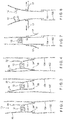
- Figure 2 illustrates a configuration with a shortened first sidewall 102, wherein the end of the first shortened sidewall 102 is sealed to the first interior flange 18.
- Figure 3 illustrates a configuration wherein the first exterior flange 16 and the second interior flange 34 are sealed to the respective first and second sidewalls 102, 104 and the first interior flange 18 and the second exterior flange 32 are free of connection to the sidewalls 102, 104.
- Figure 4 illustrates the tips of first interior and exterior flanges 16, 18 are sealed to first sidewall 102 as well as the tip of second interior flange 34 is sealed to second sidewall 104. The end of the second exterior flange 32 is free of connection to the second sidewall 104.
- Figure 5A illustrates a variation wherein sealing jaws 112, 114 seal the first exterior flange 16 to the first sidewall 102 and the second interior flange 34 to the second sidewall 104, but the first interior flange 18 and the second exterior flange 32 (with an upper edge 33) are free of sealing.
- Figure 5A illustrates the seals as shown in Figure 3 .
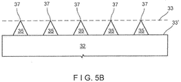
- Figure 5B illustrates an alternative embodiment with respect to Figure 5A .
- an alternative is to replace the otherwise horizontal upper edge 33 of second exterior flange 32 with an edge 33' including a plurality of upwardly extending tabs or sawteeth 35.
- the upwardly extending tabs or sawteeth 35 are typically, but not necessarily triangular and spaced periodically.
- the upper points 37 of the upwardly extending triangular tabs or sawteeth 35 are typically of the same height (i.e., the same relationship with the second sidewall 104) as the horizontal upper edge 33 of the embodiment of Figure 5A .
- the upwardly extending tabs or sawteeth 35 may be placed opposite to printed icons on the bag walls which say "Open Here” or similar instructions which will be helpful to an adult to operate the zipper 10, but will not be helpful to a young child who is unable to read or follow written instructions.
- Figure 6 adds an additional sealing jaw 116 to seal first interior flange 18 to the first sidewall 102.
- Figure 6 illustrates the seals as shown in Figure 4 .
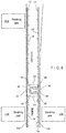
- Figures 7 and 8 illustrate a second aspect of the present disclosure.
- a regular zipper 10 is placed in the bag 100 so that the internal side and external side are reversed (i.e., the male element is enlarged on the upper or consumer side).
- the zipper 10 needs to have high opening force through profile design or by sealing it so that a shearing effect is achieved.
- Two tabs 17 are provided below the interlocking elements in order to aid in opening the bag from below (i.e., the internal side). These can be made by making a fold of the film and sealing it or by having external tabs placed on the film. The folds need to be small so that it will be necessary to pinch them between two fingers to pull the film apart, thereby opening the zipper.
- a child would try to open this bag from the top. They will most likely not figure out how to use the film folds. Even if they do figure it out, they may not have the strength to pinch and pull the folds apart.
- Utilizing the film as leverage for opening the zipper will enable various zipper designs to be used such as two flange, four flange, hinged, double zipper, or two zippers back to back (which would have the low opening force sides of the zippers face to face with the film fold in-between).
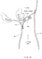
- FIG. 9 A third aspect of the disclosure is illustrated in Figures 9 , 10A , 11 , 12 and 13 .
- Figure 10A shows the cross-sectional of this third aspect.
- a proximal end of first flange 122 is attached to first side wall 102 and a proximal end of second flange 124 is attached to second sidewall 104.
- First and second flanges 122, 124 are connected by a multiple-element variable-alignment zipper 126.
- a free or distal edge 128 of second flange 124 can be tucked, releasably engaged or hidden between the first sidewall 102 and the proximal first flange 122.
- Figure 10B is similar to Figure 10A .
- Figures 10B, 10C and 10D disclose the free or distal end of second flange 124 to include a tab 128'.
- Tab 128' is typically, but not necessarily, square or rectangular shaped.
- Tab 128' can be used to manually grab the second flange 124 and pull the second flange 124 away from the first flange.
- the tab 128' can be releasably engaged between the first flange 122 and the first wall.
- a proximal end of curtain 125 is connected to second sidewall 104 proximate to where second flange 124 is connected to second sidewall 104 (or, alternately, may be connected to the second flange 124).
- the free or distal end of curtain 125 is releasably engaged within an intersection of the first flange 122 and an interior of the first wall 102 to conceal the tab 128' on second flange 124, thereby causing the zipper, closure or reclosure 10 to be even more perplexing for a child to operate.
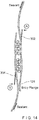
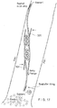
- FIGS 14-17 Still further variations of the third aspect of this disclosure are illustrated in Figures 14-17 .
- This configuration makes the zipper of the third aspect machine guidable.
- Virtually any profile configuration can be used. It can be used in virtually any horizontal form fill seal or premade application.
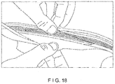
- Guide flanges 302, 304 are added to the respective zipper profiles. The zipper is guided by aligning the guides 306, 308 that fit between the guide flanges and their respective zipper flanges. Guides 306, 308 also serve to assure that the pairs of sealing bars 112, 114 and 116, 118 each seal only one sidewall to the respective profile. The resulting product is shown in Figures 18 and 19 .
- FIGS 20A-20D Various alternative embodiments of the fourth aspect of the disclosure are illustrated in Figures 20A-20D .
- This aspect includes bag flaps which are on the inside of the dispensing side of the bag or pouch 500.
- the flaps can be of separate material attached to the inside of the bag or integral with the bag material. The end of the one flap fits into the fold or point of attachment on the other flap.
- the illustrated aspect may call for materials to be put inside the dispensing portion of the bag formed by the outside film 502 which is folded to as to create first wall 529 and second wall 531, so as to create an "s" turn, thereby making the contents less accessible to children.
- the flap itself can be created by attaching materials to form a C-fold with a single flap in the middle of the C-fold.
- bag 500 is formed of walls 529 and 531 wherein first flap 509 is attached to first wall 529 immediately below the first zipper profile 506 of zipper 504.
- the second flap 510 is formed with a V-shape and is attached to second wall 531 below the second profile 508 of zipper 504.
- the second flap 510 includes a proximal portion 512 which is attached to the second wall 531 and a distal portion 514 which is tucked under first flap 509.
- first flap 509 is formed by folding down the first wall 529.
- First zipper profile 506 of the zipper 504 is attached to the first flap 509.
- the right wall 531 is folded in an S-configuration so as to create proximate portion 512 of second flap 510 and distal portion 514 of second flap 510.
- Second zipper profile 508 is attached to proximal portion 512 of second flap 510.
- Distal portion 514 is tucked under first flap 509.
- Figure 20C is similar to Figure 20A except that first flap 509 is formed as an integral flange with first zipper profile 506 and second flap 510 is formed as an integral flange with second zipper profile 508.
- Figure 20D is similar to Figure 20B except that the zipper is replaced with a peel seal 540, shown in a separated configuration.
- the flap can be created in a variety of configurations.
- the zipper may be installed in a machine or transverse direction during manufacture.
Landscapes
- Engineering & Computer Science (AREA)
- Mechanical Engineering (AREA)
- Bag Frames (AREA)
Abstract
Description
- The present application is a continuation-in-part of application serial no.
13/973,312, filed on August 22, 2013 61/717,715, which was filed on October 24, 2012 - The present disclosure relates to various embodiments of child-resistant reclosable packages or bags.
- The prior art includes various child-resistant packages. Typically, these packages are designed to hold medicinal capsules, detergent capsules, or similar items which might be attractive, but harmful, to a child. The prior art has many examples of plastic lids, in order to be removed from the glass or plastic container, which must be squeezed or pushed in various ways which would not be apparent to a child or would be beyond the strength capabilities of the child. However, such containers are complicated to manufacture and add a considerable expense to the consumer product. Additionally, such containers may be heavy and bulky which adds to the costs of transportation. Furthermore, this weight and bulk adds to the recycling burden of these products.
- It is therefore an object of the present disclosure to provide child-resistant containers which maintain a high level of child resistance, while achieving reduced weight and costs with respect to manufacture, transportation and recycling.
- These and other objects are obtained by a polymeric or plastic container with various zipper configurations, including zipper configurations with a high internal opening force and a low external opening force. Such configurations include zippers where only three flanges are sealed, so if the child attempts to open the bag by pulling the external part of the bag, the high opening force of the zipper is encountered. In order to encounter the low external opening force, the user must grab the unsealed external flange while attempting to open the bag.
- Further objects and advantages of the disclosure will become apparent from the following description and from the accompanying drawings, wherein:
-
Figure 1 is a cross-sectional view of a zipper as attached to the side walls of a plastic bag or container, thereby resulting in the first embodiment of the present disclosure. -
Figures 2-4 are cross-sectional views of variations of the embodiment ofFigure 1 . -
Figure 5A illustrates a first configuration of sealing jaws in the first aspect of the present disclosure. -
Figure 5B illustrates an alternative upper edge of the flange ofFigure 5A . -
Figure 6 illustrates a second configuration of sealing jaws in the first aspect of the present disclosure. -
Figures 7 and 8 illustrate the open and closed configuration of the second aspect of the present disclosure. -
Figure 9 illustrates a cross-sectional view of a third aspect of the present disclosure. -
Figures 10A ,11 ,12 and13 illustrate the opening sequence for a third aspect of the present disclosure. -
Figures 10B illustrates an alternative embodiment of the third aspect of the present disclosure. -
Figure 10C illustrates the tab of the alternative embodiment of the third aspect of the present disclosure. -
Figure 10D illustrates the curtain of the third aspect of the present disclosure concealing the tab of the second flange (shown in phantom). -
Figures 14 ,15 ,16 and17 illustrate various methods of manufacture for a variation of the third aspect of the present disclosure. -
Figures 18 and19 illustrate a further variation of the third aspect of the present disclosure. -
Figures 20A-20D illustrate the fourth aspect of the present disclosure. - Pursuant to this disclosure, one sees that
Figures 1-6 relate to a first aspect of the present disclosure. InFigure 1 , zipper, reclosure orclosure 10 includes first andsecond profiles First profile 12 includes a firstexterior flange 16 and a firstinterior flange 18 as well as afemale interlocking element 20 formed from first and second upwardly extendingarms detent hooks second profile 14 includes secondexterior flange 32 and a secondinterior flange 34 as well as amale interlocking element 36 formed from apost 38 and anarrowhead element 40. Theinterior wing 42 ofarrowhead element 40 is more enlarged and protruding than theexterior wing 44 ofarrowhead element 40. This causes the interior or product side or inside opening force to be greater than the exterior or consumer side or outside opening force. - First and
second profiles second sidewalls bag 100. Of course,sidewalls storage volume 106 in the interior of thebag 100. Firstexterior flange 16 and firstinterior flange 18 are sealed tofirst sidewall 102 so that the firstexterior flange 16 is oriented toward the consumer side of the zipper and the firstinterior flange 18 is oriented toward the product side of the zipper. Likewise, secondinterior flange 34 is sealed tosecond sidewall 104 so that the second exterior flange 32 (with a horizontal upper edge 33) is oriented toward the consumer side of the zipper and the secondinterior flange 34 is oriented toward the product side of the zipper. However, secondexterior flange 32 is free of sealing to thesecond sidewall 104. In this configuration, if a child grabbed the first andsecond sidewalls second sidewall 104 would transmit the opening forces to the interior side of the female andmale interlocking elements zipper 10 very difficult, if not impossible, to open with regular manual forces. However, if one grabbed the secondexterior flange 32 and thefirst sidewall 102, and pulled them apart, the lower exterior opening force will be encountered and the zipper will easily open. -
Figure 2 illustrates a configuration with a shortenedfirst sidewall 102, wherein the end of the first shortenedsidewall 102 is sealed to the firstinterior flange 18.Figure 3 illustrates a configuration wherein the firstexterior flange 16 and the secondinterior flange 34 are sealed to the respective first andsecond sidewalls interior flange 18 and the secondexterior flange 32 are free of connection to thesidewalls Figure 4 illustrates the tips of first interior andexterior flanges first sidewall 102 as well as the tip of secondinterior flange 34 is sealed tosecond sidewall 104. The end of the secondexterior flange 32 is free of connection to thesecond sidewall 104. -
Figure 5A illustrates a variation whereinsealing jaws exterior flange 16 to thefirst sidewall 102 and the secondinterior flange 34 to thesecond sidewall 104, but the firstinterior flange 18 and the second exterior flange 32 (with an upper edge 33) are free of sealing.Figure 5A illustrates the seals as shown inFigure 3 . -
Figure 5B illustrates an alternative embodiment with respect toFigure 5A . As shown inFigure 5B , an alternative is to replace the otherwise horizontalupper edge 33 of secondexterior flange 32 with an edge 33' including a plurality of upwardly extending tabs orsawteeth 35. The upwardly extending tabs orsawteeth 35 are typically, but not necessarily triangular and spaced periodically. Theupper points 37 of the upwardly extending triangular tabs orsawteeth 35 are typically of the same height (i.e., the same relationship with the second sidewall 104) as the horizontalupper edge 33 of the embodiment ofFigure 5A . As it is more difficult for the user to grip the upwardly extending tabs orsawteeth 35 rather than the fullupper edge 33 of the secondexterior flange 32, the resulting configuration is intended to become more child-resistant. The upwardly extending tabs orsawteeth 35 may be placed opposite to printed icons on the bag walls which say "Open Here" or similar instructions which will be helpful to an adult to operate thezipper 10, but will not be helpful to a young child who is unable to read or follow written instructions. -
Figure 6 adds anadditional sealing jaw 116 to seal firstinterior flange 18 to thefirst sidewall 102.Figure 6 illustrates the seals as shown inFigure 4 . -
Figures 7 and 8 illustrate a second aspect of the present disclosure. Aregular zipper 10 is placed in thebag 100 so that the internal side and external side are reversed (i.e., the male element is enlarged on the upper or consumer side). Thezipper 10 needs to have high opening force through profile design or by sealing it so that a shearing effect is achieved. Twotabs 17 are provided below the interlocking elements in order to aid in opening the bag from below (i.e., the internal side). These can be made by making a fold of the film and sealing it or by having external tabs placed on the film. The folds need to be small so that it will be necessary to pinch them between two fingers to pull the film apart, thereby opening the zipper. Typically, a child would try to open this bag from the top. They will most likely not figure out how to use the film folds. Even if they do figure it out, they may not have the strength to pinch and pull the folds apart. - Utilizing the film as leverage for opening the zipper will enable various zipper designs to be used such as two flange, four flange, hinged, double zipper, or two zippers back to back (which would have the low opening force sides of the zippers face to face with the film fold in-between).
- A third aspect of the disclosure is illustrated in
Figures 9 ,10A ,11 ,12 and13 .Figure 10A shows the cross-sectional of this third aspect. A proximal end offirst flange 122 is attached tofirst side wall 102 and a proximal end ofsecond flange 124 is attached tosecond sidewall 104. First andsecond flanges alignment zipper 126. A free ordistal edge 128 ofsecond flange 124 can be tucked, releasably engaged or hidden between thefirst sidewall 102 and the proximalfirst flange 122. It would not be intuitive for a user, particularly a young user, to grasp the downwardly-pointing edge 128 of thesecond flange 124. However, if the consumer does not do this, this configuration will go into shear mode when attempted to be opened from either the consumer side of the package or the film or product side (pinch grip and pull). This configuration eliminates the reliance of opening forces and subsequent placement of film grip areas. - A further variation of the third aspect of this disclosure is illustrated in
Figures 10B, 10C and 10D. Figure 10B is similar toFigure 10A . However,Figures 10B, 10C and 10D disclose the free or distal end ofsecond flange 124 to include a tab 128'. Tab 128' is typically, but not necessarily, square or rectangular shaped. Tab 128' can be used to manually grab thesecond flange 124 and pull thesecond flange 124 away from the first flange. Moreover, as further shown inFigure 10B , the tab 128' can be releasably engaged between thefirst flange 122 and the first wall. Furthermore, a proximal end ofcurtain 125 is connected tosecond sidewall 104 proximate to wheresecond flange 124 is connected to second sidewall 104 (or, alternately, may be connected to the second flange 124). As shown inFigure 10D , the free or distal end ofcurtain 125 is releasably engaged within an intersection of thefirst flange 122 and an interior of thefirst wall 102 to conceal the tab 128' onsecond flange 124, thereby causing the zipper, closure orreclosure 10 to be even more perplexing for a child to operate. - Still further variations of the third aspect of this disclosure are illustrated in
Figures 14-17 . This configuration makes the zipper of the third aspect machine guidable. Virtually any profile configuration can be used. It can be used in virtually any horizontal form fill seal or premade application.Guide flanges guides Guides bars Figures 18 and19 . - Various alternative embodiments of the fourth aspect of the disclosure are illustrated in
Figures 20A-20D . This aspect includes bag flaps which are on the inside of the dispensing side of the bag orpouch 500. The flaps can be of separate material attached to the inside of the bag or integral with the bag material. The end of the one flap fits into the fold or point of attachment on the other flap. The illustrated aspect may call for materials to be put inside the dispensing portion of the bag formed by theoutside film 502 which is folded to as to createfirst wall 529 andsecond wall 531, so as to create an "s" turn, thereby making the contents less accessible to children. The flap itself can be created by attaching materials to form a C-fold with a single flap in the middle of the C-fold. If the flap is tucked into the sides of the package, the flap will be tight and hard to get past without a high degree of dexterity. Furthermore, pulling the sides of the package apart to expose the flap will make it difficult to open and simultaneously stick one's hand inside. As illustrated inFigure 20A ,bag 500 is formed ofwalls first flap 509 is attached tofirst wall 529 immediately below thefirst zipper profile 506 ofzipper 504. Similarly, thesecond flap 510 is formed with a V-shape and is attached tosecond wall 531 below thesecond profile 508 ofzipper 504. Thesecond flap 510 includes aproximal portion 512 which is attached to thesecond wall 531 and adistal portion 514 which is tucked underfirst flap 509. InFigure 20B ,first flap 509 is formed by folding down thefirst wall 529.First zipper profile 506 of thezipper 504 is attached to thefirst flap 509. Theright wall 531 is folded in an S-configuration so as to createproximate portion 512 ofsecond flap 510 anddistal portion 514 ofsecond flap 510.Second zipper profile 508 is attached toproximal portion 512 ofsecond flap 510.Distal portion 514 is tucked underfirst flap 509.Figure 20C is similar toFigure 20A except thatfirst flap 509 is formed as an integral flange withfirst zipper profile 506 andsecond flap 510 is formed as an integral flange withsecond zipper profile 508.Figure 20D is similar toFigure 20B except that the zipper is replaced with apeel seal 540, shown in a separated configuration. - This results in a package which would be self-closing despite not being locked. Creating a specific path to follow to get into the package provides advantages over the prior art. Taken from the sandwich bag, the flap can be created in a variety of configurations.
- In all of these aspects of the disclosure, it is envisioned that the zipper may be installed in a machine or transverse direction during manufacture.
- Thus the several aforementioned objects and advantages are most effectively attained. Although preferred embodiments of the invention have been disclosed and described in detail herein, it should be understood that this invention is in no sense limited thereby and its scope is to be determined by that of the appended claims.
- Further aspects of the present invention are recited in the following numbered clauses:
- 1. A container or bag, including:
- a first wall and a second wall, the first wall and the second wall being joined together so as to form a storage volume therebetween and a mouth;
- a zipper attached to the first wall and second wall, thereby making the mouth reclosable, and defining an inside of the container or bag oriented toward the storage volume and an outside of the container or bag oriented toward the mouth, the zipper including:
- a first profile including a first interior flange, a first interlocking element and a first exterior flange; and
- a second profile including a second interior flange, a second interlocking element and a second exterior flange, the second exterior flange including an upper surface with a plurality of tabs extending therefrom;
- wherein the first exterior flange is attached to the first wall on an outside of the container or bag, the second interior flange is attached to the second wall on an inside of the container or bag; and
- wherein the second wall extends beyond the second exterior flange, the second exterior flange being unattached to the second bag wall, whereby opening forces applied to the outside of the second wall of the package or bag are transmitted to the second interior flange whereby increased internal opening forces are encountered upon engaging the first exterior flange and the second wall, thereby resisting access to the interior of the bag.
- 2. The container or bag of clause 1 wherein the first wall and the second wall are formed of polymeric material.
- 3. The container or bag of clause 1 wherein the zipper is formed of polymeric material.
- 4. The container or bag of clause 3 wherein the tabs are triangularly shaped.
- 5. The container or bag of
clause 4 wherein the tabs are regularly spaced from each other. - 6. The container or bag of
clause 5 wherein the first interlocking element is a first of a male and a female element and the second interlocking element is a second of a male and a female element. - 7. The container or bag of clause 6 wherein male element includes a shaft element and an arrowhead element, wherein the arrowhead includes a first side oriented toward the outside and a second side oriented toward the inside, wherein the second side is more enlarged than the first side, thereby causing inside opening forces to be greater than outside opening forces.
- 8. The container or bag of clause 7 in a child-resistant application.
- 9. A container or bag, including:
- a first wall and a second wall, the first wall and the second wall being joined together so as to form a storage volume therebetween and a mouth;
- a zipper attached to the first wall and second wall, thereby making the mouth reclosable, and defining an inside of the container or bag oriented toward the storage volume and an outside of the container or bag oriented toward the mouth, the zipper including:
- a first profile including a first flange and a first interlocking element, the first flange including a first proximal end and a first distal end; and
- a second profile including a second flange and a second interlocking element, the second flange including a second proximal end and a second distal end;
- wherein the proximal end of first flange is attached to the first wall below the first interlocking element with the first interlocking element pointing up, and the proximal end of second flange is attached to the second bag wall above the second interlocking element with the second interlocking element pointing down, wherein the tab element of the second distal end is releasably engaged within an intersection of the first proximal end of the first flange and an interior of the first wall.
- 10. The container or bag of clause 9 further including a tab element on the second distal end of the second interior flange.
- 11. The container or bag of
clause 10 further including a curtain element with a third proximal end and a third distal end, the third proximal end being attached to the second flange or the second wall, and the third distal end being releasably engaged within an intersection of the second proximal end of second flange and an interior of the first wall thereby concealing the tab element of the second interior flange. - 12. The container or bag of clause 11 wherein the first and second profiles are respective first and second multiple-element variable alignment zipper profiles.
- 13. The container or bag of
clause 12 wherein an outside opening force on the first and second walls urges an engagement of the first and second variable alignment zipper profiles into a shear mode. - 14. The container or bag of
clause 12 wherein an inside opening force on the first and second walls urges an engagement of the first and second variable alignment zipper profiles into a shear mode. - 15. The container or bag of
clause 10 wherein the tab is square or rectangular shaped. - 16. The container or bag of clause 9 wherein the first wall and the second wall are formed of polymeric material.
- 17. The container or bag of clause 9 wherein the zipper is formed of polymeric material.
Claims (8)
- A container or bag, including:a first wall and a second wall, the first wall and the second wall being joined together so as to form a storage volume therebetween and a mouth;a zipper attached to the first wall and second wall, thereby making the mouth reclosable, and defining an inside of the container or bag oriented toward the storage volume and an outside of the container or bag oriented toward the mouth, the zipper including:a first profile including a first interior flange, a first interlocking element and a first exterior flange; anda second profile including a second interior flange, a second interlocking element and a second exterior flange, the second exterior flange including an upper surface with a plurality of tabs extending therefrom;wherein the first exterior flange is attached to the first wall on an outside of the container or bag, the second interior flange is attached to the second wall on an inside of the container or bag; andwherein the second wall extends beyond the second exterior flange, the second exterior flange being unattached to the second bag wall, whereby opening forces applied to the outside of the second wall of the package or bag are transmitted to the second interior flange whereby increased internal opening forces are encountered upon engaging the first exterior flange and the second wall, thereby resisting access to the interior of the bag.
- The container or bag of Claim 1 wherein the first wall and the second wall are formed of polymeric material.
- The container or bag of Claim 1 wherein the zipper is formed of polymeric material.
- The container or bag of Claim 3 wherein the tabs are triangularly shaped.
- The container or bag of Claim 4 wherein the tabs are regularly spaced from each other.
- The container or bag of Claim 5 wherein the first interlocking element is a first of a male and a female element and the second interlocking element is a second of a male and a female element.
- The container or bag of Claim 6 wherein male element includes a shaft element and an arrowhead element, wherein the arrowhead includes a first side oriented toward the outside and a second side oriented toward the inside, wherein the second side is more enlarged than the first side, thereby causing inside opening forces to be greater than outside opening forces.
- The container or bag of Claim 7 in a child-resistant application.
Applications Claiming Priority (1)
| Application Number | Priority Date | Filing Date | Title |
|---|---|---|---|
| US15/427,333 US10287063B2 (en) | 2012-10-24 | 2017-02-08 | Child-resistant reclosable bags |
Publications (2)
| Publication Number | Publication Date |
|---|---|
| EP3360815A1 true EP3360815A1 (en) | 2018-08-15 |
| EP3360815B1 EP3360815B1 (en) | 2020-01-01 |
Family
ID=61157131
Family Applications (1)
| Application Number | Title | Priority Date | Filing Date |
|---|---|---|---|
| EP18154988.2A Active EP3360815B1 (en) | 2017-02-08 | 2018-02-02 | Child-resistant reclosable bags |
Country Status (1)
| Country | Link |
|---|---|
| EP (1) | EP3360815B1 (en) |
Cited By (4)
| Publication number | Priority date | Publication date | Assignee | Title |
|---|---|---|---|---|
| CN112623488A (en) * | 2021-01-14 | 2021-04-09 | 青岛永昇昌塑胶精密有限公司 | Plastic zipper and packaging bag using same |
| CN113242832A (en) * | 2018-12-19 | 2021-08-10 | 雷诺兹普雷斯托产品有限公司 | Hidden flange child resistant closure and method for reclosable bag |
| WO2022040250A1 (en) * | 2020-08-19 | 2022-02-24 | Illinois Tool Works Inc. | Hinged zipper assembly of a resealable enclosure |
| US11572219B2 (en) | 2019-02-08 | 2023-02-07 | Elplast Europe Sp. Z O.O. | Zipper closure and package using the same |
Citations (3)
| Publication number | Priority date | Publication date | Assignee | Title |
|---|---|---|---|---|
| EP1489019A1 (en) * | 2002-03-27 | 2004-12-22 | Idemitsu Unitech Co., Ltd. | Sealing bag with chuck |
| WO2014066025A1 (en) * | 2012-10-24 | 2014-05-01 | Illinois Tool Works Inc. | Child-resistant reclosable bags |
| WO2016034720A1 (en) * | 2014-09-04 | 2016-03-10 | S2F Flexico | Bag comprising a closure device fixed to extension webs |
-
2018
- 2018-02-02 EP EP18154988.2A patent/EP3360815B1/en active Active
Patent Citations (3)
| Publication number | Priority date | Publication date | Assignee | Title |
|---|---|---|---|---|
| EP1489019A1 (en) * | 2002-03-27 | 2004-12-22 | Idemitsu Unitech Co., Ltd. | Sealing bag with chuck |
| WO2014066025A1 (en) * | 2012-10-24 | 2014-05-01 | Illinois Tool Works Inc. | Child-resistant reclosable bags |
| WO2016034720A1 (en) * | 2014-09-04 | 2016-03-10 | S2F Flexico | Bag comprising a closure device fixed to extension webs |
Cited By (9)
| Publication number | Priority date | Publication date | Assignee | Title |
|---|---|---|---|---|
| CN113242832A (en) * | 2018-12-19 | 2021-08-10 | 雷诺兹普雷斯托产品有限公司 | Hidden flange child resistant closure and method for reclosable bag |
| US11511914B2 (en) | 2018-12-19 | 2022-11-29 | Reynolds Presto Products Inc. | Hidden flange child resistant closure for recloseable pouch and methods |
| US11530076B2 (en) | 2018-12-19 | 2022-12-20 | Reynolds Presto Products Inc. | Hidden flange child resistant closure for recloseable pouch and methods |
| US12162648B2 (en) | 2018-12-19 | 2024-12-10 | Reynolds Presto Products Inc. | Hidden flange child resistant closure for recloseable pouch and methods |
| US11572219B2 (en) | 2019-02-08 | 2023-02-07 | Elplast Europe Sp. Z O.O. | Zipper closure and package using the same |
| US12344439B2 (en) | 2019-02-08 | 2025-07-01 | Elplast Europe Sp. Z O.O. | Zipper closure and package using the same |
| WO2022040250A1 (en) * | 2020-08-19 | 2022-02-24 | Illinois Tool Works Inc. | Hinged zipper assembly of a resealable enclosure |
| CN116490436A (en) * | 2020-08-19 | 2023-07-25 | 伊利诺斯工具制品有限公司 | Pivot zipper assembly for resealable containment |
| CN112623488A (en) * | 2021-01-14 | 2021-04-09 | 青岛永昇昌塑胶精密有限公司 | Plastic zipper and packaging bag using same |
Also Published As
| Publication number | Publication date |
|---|---|
| EP3360815B1 (en) | 2020-01-01 |
Similar Documents
| Publication | Publication Date | Title |
|---|---|---|
| EP2911944B1 (en) | Child-resistant reclosable bags | |
| US10287063B2 (en) | Child-resistant reclosable bags | |
| EP3585702B1 (en) | Child resistant sealing system | |
| US11584568B2 (en) | Resealable bag | |
| US20220274748A1 (en) | Package having a child-restrictive opening feature | |
| AU2023203044B2 (en) | Hidden flange child resistant closure for recloseable pouch and methods | |
| EP3360815B1 (en) | Child-resistant reclosable bags | |
| US10351306B2 (en) | Zipper child deterrent closure with three web/flange design | |
| US20130195385A1 (en) | Tamper/child resistant bag | |
| US20050031228A1 (en) | Reclosable flexible package and method for making the same | |
| EP1132311A2 (en) | Reclosable, package having zipper closure, slider device and tampers-evident structure and methods | |
| US9624003B1 (en) | Bag with gripping bands | |
| WO2016069883A1 (en) | Closure for a reclosable package with an air pocket formed on a flange | |
| CN214325856U (en) | Reusable child-resistant zipper structure | |
| JP2015193387A (en) | Packaging container | |
| HK40050997B (en) | Hidden flange child resistant closure for recloseable pouch and methods | |
| HK40050997A (en) | Hidden flange child resistant closure for recloseable pouch and methods | |
| JPH06544B2 (en) | Bag with a retractable sealing device |
Legal Events
| Date | Code | Title | Description |
|---|---|---|---|
| PUAI | Public reference made under article 153(3) epc to a published international application that has entered the european phase |
Free format text: ORIGINAL CODE: 0009012 |
|
| STAA | Information on the status of an ep patent application or granted ep patent |
Free format text: STATUS: THE APPLICATION HAS BEEN PUBLISHED |
|
| AK | Designated contracting states |
Kind code of ref document: A1 Designated state(s): AL AT BE BG CH CY CZ DE DK EE ES FI FR GB GR HR HU IE IS IT LI LT LU LV MC MK MT NL NO PL PT RO RS SE SI SK SM TR |
|
| AX | Request for extension of the european patent |
Extension state: BA ME |
|
| STAA | Information on the status of an ep patent application or granted ep patent |
Free format text: STATUS: REQUEST FOR EXAMINATION WAS MADE |
|
| 17P | Request for examination filed |
Effective date: 20190215 |
|
| RBV | Designated contracting states (corrected) |
Designated state(s): AL AT BE BG CH CY CZ DE DK EE ES FI FR GB GR HR HU IE IS IT LI LT LU LV MC MK MT NL NO PL PT RO RS SE SI SK SM TR |
|
| RIC1 | Information provided on ipc code assigned before grant |
Ipc: B65D 33/25 20060101AFI20190307BHEP |
|
| INTG | Intention to grant announced |
Effective date: 20190617 |
|
| GRAS | Grant fee paid |
Free format text: ORIGINAL CODE: EPIDOSNIGR3 |
|
| STAA | Information on the status of an ep patent application or granted ep patent |
Free format text: STATUS: GRANT OF PATENT IS INTENDED |
|
| GRAJ | Information related to disapproval of communication of intention to grant by the applicant or resumption of examination proceedings by the epo deleted |
Free format text: ORIGINAL CODE: EPIDOSDIGR1 |
|
| GRAL | Information related to payment of fee for publishing/printing deleted |
Free format text: ORIGINAL CODE: EPIDOSDIGR3 |
|
| STAA | Information on the status of an ep patent application or granted ep patent |
Free format text: STATUS: REQUEST FOR EXAMINATION WAS MADE |
|
| INTC | Intention to grant announced (deleted) | ||
| GRAR | Information related to intention to grant a patent recorded |
Free format text: ORIGINAL CODE: EPIDOSNIGR71 |
|
| STAA | Information on the status of an ep patent application or granted ep patent |
Free format text: STATUS: GRANT OF PATENT IS INTENDED |
|
| GRAA | (expected) grant |
Free format text: ORIGINAL CODE: 0009210 |
|
| STAA | Information on the status of an ep patent application or granted ep patent |
Free format text: STATUS: THE PATENT HAS BEEN GRANTED |
|
| AK | Designated contracting states |
Kind code of ref document: B1 Designated state(s): AL AT BE BG CH CY CZ DE DK EE ES FI FR GB GR HR HU IE IS IT LI LT LU LV MC MK MT NL NO PL PT RO RS SE SI SK SM TR |
|
| INTG | Intention to grant announced |
Effective date: 20191122 |
|
| REG | Reference to a national code |
Ref country code: GB Ref legal event code: FG4D |
|
| REG | Reference to a national code |
Ref country code: CH Ref legal event code: EP Ref country code: AT Ref legal event code: REF Ref document number: 1219535 Country of ref document: AT Kind code of ref document: T Effective date: 20200115 |
|
| REG | Reference to a national code |
Ref country code: IE Ref legal event code: FG4D |
|
| REG | Reference to a national code |
Ref country code: DE Ref legal event code: R096 Ref document number: 602018001807 Country of ref document: DE |
|
| REG | Reference to a national code |
Ref country code: NL Ref legal event code: MP Effective date: 20200101 |
|
| REG | Reference to a national code |
Ref country code: LT Ref legal event code: MG4D |
|
| PG25 | Lapsed in a contracting state [announced via postgrant information from national office to epo] |
Ref country code: RS Free format text: LAPSE BECAUSE OF FAILURE TO SUBMIT A TRANSLATION OF THE DESCRIPTION OR TO PAY THE FEE WITHIN THE PRESCRIBED TIME-LIMIT Effective date: 20200101 Ref country code: LT Free format text: LAPSE BECAUSE OF FAILURE TO SUBMIT A TRANSLATION OF THE DESCRIPTION OR TO PAY THE FEE WITHIN THE PRESCRIBED TIME-LIMIT Effective date: 20200101 Ref country code: PT Free format text: LAPSE BECAUSE OF FAILURE TO SUBMIT A TRANSLATION OF THE DESCRIPTION OR TO PAY THE FEE WITHIN THE PRESCRIBED TIME-LIMIT Effective date: 20200527 Ref country code: NL Free format text: LAPSE BECAUSE OF FAILURE TO SUBMIT A TRANSLATION OF THE DESCRIPTION OR TO PAY THE FEE WITHIN THE PRESCRIBED TIME-LIMIT Effective date: 20200101 Ref country code: CZ Free format text: LAPSE BECAUSE OF FAILURE TO SUBMIT A TRANSLATION OF THE DESCRIPTION OR TO PAY THE FEE WITHIN THE PRESCRIBED TIME-LIMIT Effective date: 20200101 Ref country code: FI Free format text: LAPSE BECAUSE OF FAILURE TO SUBMIT A TRANSLATION OF THE DESCRIPTION OR TO PAY THE FEE WITHIN THE PRESCRIBED TIME-LIMIT Effective date: 20200101 Ref country code: NO Free format text: LAPSE BECAUSE OF FAILURE TO SUBMIT A TRANSLATION OF THE DESCRIPTION OR TO PAY THE FEE WITHIN THE PRESCRIBED TIME-LIMIT Effective date: 20200401 |
|
| PG25 | Lapsed in a contracting state [announced via postgrant information from national office to epo] |
Ref country code: SE Free format text: LAPSE BECAUSE OF FAILURE TO SUBMIT A TRANSLATION OF THE DESCRIPTION OR TO PAY THE FEE WITHIN THE PRESCRIBED TIME-LIMIT Effective date: 20200101 Ref country code: LV Free format text: LAPSE BECAUSE OF FAILURE TO SUBMIT A TRANSLATION OF THE DESCRIPTION OR TO PAY THE FEE WITHIN THE PRESCRIBED TIME-LIMIT Effective date: 20200101 Ref country code: HR Free format text: LAPSE BECAUSE OF FAILURE TO SUBMIT A TRANSLATION OF THE DESCRIPTION OR TO PAY THE FEE WITHIN THE PRESCRIBED TIME-LIMIT Effective date: 20200101 Ref country code: IS Free format text: LAPSE BECAUSE OF FAILURE TO SUBMIT A TRANSLATION OF THE DESCRIPTION OR TO PAY THE FEE WITHIN THE PRESCRIBED TIME-LIMIT Effective date: 20200501 Ref country code: BG Free format text: LAPSE BECAUSE OF FAILURE TO SUBMIT A TRANSLATION OF THE DESCRIPTION OR TO PAY THE FEE WITHIN THE PRESCRIBED TIME-LIMIT Effective date: 20200401 Ref country code: GR Free format text: LAPSE BECAUSE OF FAILURE TO SUBMIT A TRANSLATION OF THE DESCRIPTION OR TO PAY THE FEE WITHIN THE PRESCRIBED TIME-LIMIT Effective date: 20200402 |
|
| REG | Reference to a national code |
Ref country code: DE Ref legal event code: R097 Ref document number: 602018001807 Country of ref document: DE |
|
| REG | Reference to a national code |
Ref country code: BE Ref legal event code: MM Effective date: 20200229 |
|
| PG25 | Lapsed in a contracting state [announced via postgrant information from national office to epo] |
Ref country code: RO Free format text: LAPSE BECAUSE OF FAILURE TO SUBMIT A TRANSLATION OF THE DESCRIPTION OR TO PAY THE FEE WITHIN THE PRESCRIBED TIME-LIMIT Effective date: 20200101 Ref country code: SK Free format text: LAPSE BECAUSE OF FAILURE TO SUBMIT A TRANSLATION OF THE DESCRIPTION OR TO PAY THE FEE WITHIN THE PRESCRIBED TIME-LIMIT Effective date: 20200101 Ref country code: EE Free format text: LAPSE BECAUSE OF FAILURE TO SUBMIT A TRANSLATION OF THE DESCRIPTION OR TO PAY THE FEE WITHIN THE PRESCRIBED TIME-LIMIT Effective date: 20200101 Ref country code: SM Free format text: LAPSE BECAUSE OF FAILURE TO SUBMIT A TRANSLATION OF THE DESCRIPTION OR TO PAY THE FEE WITHIN THE PRESCRIBED TIME-LIMIT Effective date: 20200101 Ref country code: LU Free format text: LAPSE BECAUSE OF NON-PAYMENT OF DUE FEES Effective date: 20200202 Ref country code: DK Free format text: LAPSE BECAUSE OF FAILURE TO SUBMIT A TRANSLATION OF THE DESCRIPTION OR TO PAY THE FEE WITHIN THE PRESCRIBED TIME-LIMIT Effective date: 20200101 Ref country code: ES Free format text: LAPSE BECAUSE OF FAILURE TO SUBMIT A TRANSLATION OF THE DESCRIPTION OR TO PAY THE FEE WITHIN THE PRESCRIBED TIME-LIMIT Effective date: 20200101 Ref country code: MC Free format text: LAPSE BECAUSE OF FAILURE TO SUBMIT A TRANSLATION OF THE DESCRIPTION OR TO PAY THE FEE WITHIN THE PRESCRIBED TIME-LIMIT Effective date: 20200101 |
|
| PLBE | No opposition filed within time limit |
Free format text: ORIGINAL CODE: 0009261 |
|
| STAA | Information on the status of an ep patent application or granted ep patent |
Free format text: STATUS: NO OPPOSITION FILED WITHIN TIME LIMIT |
|
| REG | Reference to a national code |
Ref country code: AT Ref legal event code: MK05 Ref document number: 1219535 Country of ref document: AT Kind code of ref document: T Effective date: 20200101 |
|
| 26N | No opposition filed |
Effective date: 20201002 |
|
| PG25 | Lapsed in a contracting state [announced via postgrant information from national office to epo] |
Ref country code: IE Free format text: LAPSE BECAUSE OF NON-PAYMENT OF DUE FEES Effective date: 20200202 Ref country code: AT Free format text: LAPSE BECAUSE OF FAILURE TO SUBMIT A TRANSLATION OF THE DESCRIPTION OR TO PAY THE FEE WITHIN THE PRESCRIBED TIME-LIMIT Effective date: 20200101 |
|
| PG25 | Lapsed in a contracting state [announced via postgrant information from national office to epo] |
Ref country code: BE Free format text: LAPSE BECAUSE OF NON-PAYMENT OF DUE FEES Effective date: 20200229 Ref country code: PL Free format text: LAPSE BECAUSE OF FAILURE TO SUBMIT A TRANSLATION OF THE DESCRIPTION OR TO PAY THE FEE WITHIN THE PRESCRIBED TIME-LIMIT Effective date: 20200101 Ref country code: SI Free format text: LAPSE BECAUSE OF FAILURE TO SUBMIT A TRANSLATION OF THE DESCRIPTION OR TO PAY THE FEE WITHIN THE PRESCRIBED TIME-LIMIT Effective date: 20200101 |
|
| PG25 | Lapsed in a contracting state [announced via postgrant information from national office to epo] |
Ref country code: LI Free format text: LAPSE BECAUSE OF NON-PAYMENT OF DUE FEES Effective date: 20210228 Ref country code: CH Free format text: LAPSE BECAUSE OF NON-PAYMENT OF DUE FEES Effective date: 20210228 |
|
| PG25 | Lapsed in a contracting state [announced via postgrant information from national office to epo] |
Ref country code: TR Free format text: LAPSE BECAUSE OF FAILURE TO SUBMIT A TRANSLATION OF THE DESCRIPTION OR TO PAY THE FEE WITHIN THE PRESCRIBED TIME-LIMIT Effective date: 20200101 Ref country code: MT Free format text: LAPSE BECAUSE OF FAILURE TO SUBMIT A TRANSLATION OF THE DESCRIPTION OR TO PAY THE FEE WITHIN THE PRESCRIBED TIME-LIMIT Effective date: 20200101 Ref country code: CY Free format text: LAPSE BECAUSE OF FAILURE TO SUBMIT A TRANSLATION OF THE DESCRIPTION OR TO PAY THE FEE WITHIN THE PRESCRIBED TIME-LIMIT Effective date: 20200101 |
|
| PG25 | Lapsed in a contracting state [announced via postgrant information from national office to epo] |
Ref country code: MK Free format text: LAPSE BECAUSE OF FAILURE TO SUBMIT A TRANSLATION OF THE DESCRIPTION OR TO PAY THE FEE WITHIN THE PRESCRIBED TIME-LIMIT Effective date: 20200101 Ref country code: AL Free format text: LAPSE BECAUSE OF FAILURE TO SUBMIT A TRANSLATION OF THE DESCRIPTION OR TO PAY THE FEE WITHIN THE PRESCRIBED TIME-LIMIT Effective date: 20200101 |
|
| PGFP | Annual fee paid to national office [announced via postgrant information from national office to epo] |
Ref country code: IT Payment date: 20230221 Year of fee payment: 6 |
|
| P01 | Opt-out of the competence of the unified patent court (upc) registered |
Effective date: 20230606 |
|
| PG25 | Lapsed in a contracting state [announced via postgrant information from national office to epo] |
Ref country code: IT Free format text: LAPSE BECAUSE OF NON-PAYMENT OF DUE FEES Effective date: 20240202 |
|
| PGFP | Annual fee paid to national office [announced via postgrant information from national office to epo] |
Ref country code: GB Payment date: 20260227 Year of fee payment: 9 |
|
| PGFP | Annual fee paid to national office [announced via postgrant information from national office to epo] |
Ref country code: DE Payment date: 20260227 Year of fee payment: 9 |
|
| PGFP | Annual fee paid to national office [announced via postgrant information from national office to epo] |
Ref country code: FR Payment date: 20260225 Year of fee payment: 9 |