EP3360784A1 - Composite fan cowl with a core having tailored thickness - Google Patents
Composite fan cowl with a core having tailored thickness Download PDFInfo
- Publication number
- EP3360784A1 EP3360784A1 EP17194463.0A EP17194463A EP3360784A1 EP 3360784 A1 EP3360784 A1 EP 3360784A1 EP 17194463 A EP17194463 A EP 17194463A EP 3360784 A1 EP3360784 A1 EP 3360784A1
- Authority
- EP
- European Patent Office
- Prior art keywords
- thickness
- fan cowl
- core
- composite fan
- areas
- Prior art date
- Legal status (The legal status is an assumption and is not a legal conclusion. Google has not performed a legal analysis and makes no representation as to the accuracy of the status listed.)
- Pending
Links
Images



Classifications
-
- B—PERFORMING OPERATIONS; TRANSPORTING
- B64—AIRCRAFT; AVIATION; COSMONAUTICS
- B64D—EQUIPMENT FOR FITTING IN OR TO AIRCRAFT; FLIGHT SUITS; PARACHUTES; ARRANGEMENT OR MOUNTING OF POWER PLANTS OR PROPULSION TRANSMISSIONS IN AIRCRAFT
- B64D29/00—Power-plant nacelles, fairings or cowlings
- B64D29/04—Power-plant nacelles, fairings or cowlings associated with fuselages
-
- B—PERFORMING OPERATIONS; TRANSPORTING
- B64—AIRCRAFT; AVIATION; COSMONAUTICS
- B64D—EQUIPMENT FOR FITTING IN OR TO AIRCRAFT; FLIGHT SUITS; PARACHUTES; ARRANGEMENT OR MOUNTING OF POWER PLANTS OR PROPULSION TRANSMISSIONS IN AIRCRAFT
- B64D29/00—Power-plant nacelles, fairings or cowlings
- B64D29/08—Inspection panels for power plants
-
- F—MECHANICAL ENGINEERING; LIGHTING; HEATING; WEAPONS; BLASTING
- F01—MACHINES OR ENGINES IN GENERAL; ENGINE PLANTS IN GENERAL; STEAM ENGINES
- F01D—NON-POSITIVE DISPLACEMENT MACHINES OR ENGINES, e.g. STEAM TURBINES
- F01D25/00—Component parts, details, or accessories, not provided for in, or of interest apart from, other groups
- F01D25/28—Supporting or mounting arrangements, e.g. for turbine casing
-
- B—PERFORMING OPERATIONS; TRANSPORTING
- B64—AIRCRAFT; AVIATION; COSMONAUTICS
- B64C—AEROPLANES; HELICOPTERS
- B64C1/00—Fuselages; Constructional features common to fuselages, wings, stabilising surfaces or the like
- B64C2001/0054—Fuselage structures substantially made from particular materials
- B64C2001/0072—Fuselage structures substantially made from particular materials from composite materials
-
- B—PERFORMING OPERATIONS; TRANSPORTING
- B64—AIRCRAFT; AVIATION; COSMONAUTICS
- B64D—EQUIPMENT FOR FITTING IN OR TO AIRCRAFT; FLIGHT SUITS; PARACHUTES; ARRANGEMENT OR MOUNTING OF POWER PLANTS OR PROPULSION TRANSMISSIONS IN AIRCRAFT
- B64D29/00—Power-plant nacelles, fairings or cowlings
- B64D29/06—Attaching of nacelles, fairings or cowlings
-
- F—MECHANICAL ENGINEERING; LIGHTING; HEATING; WEAPONS; BLASTING
- F05—INDEXING SCHEMES RELATING TO ENGINES OR PUMPS IN VARIOUS SUBCLASSES OF CLASSES F01-F04
- F05D—INDEXING SCHEME FOR ASPECTS RELATING TO NON-POSITIVE-DISPLACEMENT MACHINES OR ENGINES, GAS-TURBINES OR JET-PROPULSION PLANTS
- F05D2240/00—Components
- F05D2240/10—Stators
- F05D2240/14—Casings or housings protecting or supporting assemblies within
-
- Y—GENERAL TAGGING OF NEW TECHNOLOGICAL DEVELOPMENTS; GENERAL TAGGING OF CROSS-SECTIONAL TECHNOLOGIES SPANNING OVER SEVERAL SECTIONS OF THE IPC; TECHNICAL SUBJECTS COVERED BY FORMER USPC CROSS-REFERENCE ART COLLECTIONS [XRACs] AND DIGESTS
- Y02—TECHNOLOGIES OR APPLICATIONS FOR MITIGATION OR ADAPTATION AGAINST CLIMATE CHANGE
- Y02T—CLIMATE CHANGE MITIGATION TECHNOLOGIES RELATED TO TRANSPORTATION
- Y02T50/00—Aeronautics or air transport
- Y02T50/40—Weight reduction
Definitions
- the present disclosure relates generally to composite fan cowls, and more specifically, to composite fan cowls with a reduced weight. Yet more specifically, the present disclosure includes a composite fan cowl with a core having tailored thickness.
- An engine nacelle is a housing connected to an aircraft covering an engine of the aircraft. Air enters through an inlet of the nacelle, travels through the nacelle and exits through the exhaust. Fan cowls form the body of the nacelle.
- the fan cowls are associated with hinges and latches to facilitate movement of the fan cowls for maintenance.
- the latches secure the fan cowls in a closed position. When the latches are released, the fan cowls pivot relative to the rest of the nacelle using the hinges.
- a composite fan cowl connected to hold open rods comprises hold open rods, laminate skins, and a core with areas of increased thickness associated with the hold open rods.
- a composite fan cowl in another illustrative example, comprises a core with a hinge zone having a first thickness, a body zone having a second thickness, and two areas of increased thickness including a third thickness, wherein the two areas of increased thickness are positioned within the body zone, wherein the first thickness and second thickness are different from each other, wherein the two areas of increased thickness have a greater thickness than the second thickness, and wherein the first thickness and second thickness are in the range of 0.5 inches and 1.5 inches.
- an engine nacelle comprising a top portion with hinges, and a composite fan cowl pivotally connected to the top portion by the hinges.
- the composite fan cowl comprising a core with a hinge zone having a first thickness and a body zone having a second thickness, wherein the hinge zone includes the hinges, wherein the body zone is distal from the hinge zone, and wherein the first thickness is less than the second thickness.
- the different illustrative examples recognize and take into account one or more different considerations. For example, the illustrative examples recognize and take into account that the weight of an aircraft may be reduced by reducing the weight of an engine nacelle. More specifically, the illustrative examples recognize and take into account that the weight of an engine nacelle may be reduced by reducing the weight of the composite fan cowls.
- a composite fan cowl is a composite panel.
- the illustrative examples recognize and take into account that a composite panel may be considered a composite sandwich panel when the composite panel is comprised of a core layer of material that is sandwiched between a first layer of material and a second layer of material.
- the core layer of material may have a greater thickness than the first and second layers of material.
- the core layer of material may be hollow or have a gas contained within the core material.
- the core layer of material may be comprised of a honeycomb material, a foam material, or some other suitable type of structure.
- a honeycomb material may be a material that has a honeycomb-like structure.
- the core may be tailored to reduce the weight of the composite fan cowl. More specifically, the illustrative examples recognize and take into account that portions of the core may have a reduced thickness to reduce the weight of the composite fan cowl without undesirably increasing the deformation of the composite fan cowl. More specifically, the illustrative examples recognize and take into account that areas of higher thicknesses may provide stiffened areas of the core. Yet more specifically, the illustrative examples recognize and take into account that portions of the core having lower bending moments may have a reduced thickness.
- aircraft 100 has wing 102 and wing 104 connected to body 106.
- Aircraft 100 includes engine 108 connected to wing 102 and engine 110 connected to wing 104.
- Body 106 has tail section 112. Horizontal stabilizer 114, horizontal stabilizer 116, and vertical stabilizer 118 are connected to tail section 112 of body 106.
- Aircraft 100 is an example of an aircraft having a composite fan cowl with a core having a tailored thickness as described.
- at least one of engine 108 or engine 110 may have a composite fan cowl with a core having varying thickness as described herein.
- the phrase "at least one of,” when used with a list of items, means different combinations of one or more of the listed items may be used, and only one of each item in the list may be needed. In other words, “at least one of” means any combination of items or number of items may be used from the list, but not all of the items in the list are required.
- the item may be a particular object, a thing, or a category.
- “at least one of item A, item B, or item C” may include, without limitation, item A, item A and item B, or item B. This example also may include item A, item B, and item C or item B and item C. Of course, any combination of these items may be present. In other examples, "at least one of” may be, for example, without limitation, two of item A, one of item B, and ten of item C; four of item B and seven of item C; or other suitable combinations.
- aircraft 100 is provided for purposes of illustrating one environment in which the different illustrative examples may be implemented.
- the illustration of aircraft 100 in Figure 1 is not meant to imply architectural limitations as to the manner in which different illustrative examples may be implemented.
- aircraft 100 is shown as a commercial passenger aircraft.
- the different illustrative examples may be applied to other types of aircraft, such as a private passenger aircraft, a rotorcraft, or other suitable types of aircraft.
- Aircraft 100 of Figure 1 may be a physical implementation of aircraft 200.
- Aircraft 200 has engine nacelle 202.
- Engine nacelle 202 has inlet 204, exhaust 206, and composite fan cowl 208.
- Composite fan cowl 208 comprises laminate skins 209 and core 210.
- Laminate skins 209 are formed of any desirable material and have any desirable number of plies. A number of plies of each of laminate skins 209 is independent of the plurality of core thicknesses of core 210. A thickness of each of laminate skins 209 is independent of thicknesses of core 210.
- Core 210 is formed of any desirable material.
- core 210 is a honeycomb core.
- core 210 may be formed of a foam.
- core 210 may be formed of another lightweight, high strength material.
- Core 210 has layout 212.
- Layout 212 is designed to reduce the weight of core 210 while maintaining performance of composite fan cowl 208.
- Layout 212 includes tailoring of thickness 213 of core 210.
- Layout 212 includes a quantity of, sizes of, and thicknesses for a plurality of zones of core 210.
- Layout 212 is designed based on a bending moment of composite fan cowl 208 when subjected to wind gusts when composite fan cowl 208 is in an open position. Layout 212 is designed such that a measure of deformation of composite fan cowl 208 due to wind gusts is substantially the same as a measure of deformation of a conventional composite fan cowl. Layout 212 may be designed such that a measure of deformation of composite fan cowl 208 due to wind gusts is maintained or reduced.
- Hinges 214 are in top portion 216 of engine nacelle 202.
- Composite fan cowl 208 is pivotally connected to top portion 216 with hinges 214.
- Composite fan cowl 208 pivots relative to the remainder of engine nacelle 202 using hinges 214.
- Hinges 214 connect to composite fan cowl 208 in hinge zone 218.
- Hinge zone 218 has first thickness 220.
- First thickness 220 is selected based on performance characteristics for core 210. In some illustrative examples, first thickness 220 may be less than a thickness for a hinge zone of a conventional composite fan cowl. When first thickness 220 is less than a conventional hinge zone thickness, composite fan cowl 208 may be lighter than a conventional composite fan cowl.
- Power door open system (PDOS) 222 is associated with composite fan cowl 208. Power door open system (PDOS) 222 actuates movement of composite fan cowl 208 relative to the remainder of engine nacelle 202. Power door open system (PDOS) 222 is associated with core 210 within hinge zone 218. First thickness 220 provides support and stiffness sufficient for the functioning of power door open system (PDOS) 222 of engine nacelle 202.
- Composite fan cowl 208 is connected to hold open rods 224. After moving composite fan cowl 208 using power door open system (PDOS) 222, composite fan cowl 208 is held open using hold open rods 224. Hold open rods 224 include hold open rod (HOR) 226 and hold open rod (HOR) 228.
- HOR hold open rod
- HOR hold open rod
- composite fan cowl 208 may be rotated to a closed position using hinges 214.
- Latches 230 secure composite fan cowl 208 relative to the remainder of engine nacelle 202 when composite fan cowl 208 is in a closed position.
- Latches 230 connect to composite fan cowl 208 in body zone 232.
- Body zone 232 is distal from hinge zone 218.
- Hinge zone 218 is above body zone 232 along arc 233 of core 210.
- Body zone 232 has second thickness 234.
- Second thickness 234 is selected based on bending moment intensities of composite fan cowl 208.
- first thickness 220 is less than second thickness 234.
- first thickness 220 is at least 10% less than second thickness 234.
- core 210 has areas of increased thickness 236 associated with hold open rods 224. Areas of increased thickness 236 each comprise a ramp up, a pad, and a ramp down in a direction of arc 233 of the core 210.
- area of increased thickness 240 includes ramp up 242, pad 244, and ramp down 246.
- Area of increased thickness 248 includes ramp up 250, pad 252, and ramp down 254. Areas of increased thickness 236 are positioned within body zone 232.
- the two areas of increased thickness 236 of core 210 comprise a plurality of ramps.
- the plurality of ramps comprises a ramp up for each of the two areas of increased thickness 236 and a ramp down for each of the two areas of increased thickness 236.
- the ramp up for each of the two areas of increased thickness 236 progressively increases in thickness from second thickness 234 to third thickness 256.
- the ramp down for each of the two areas of increased thickness 236 progressively decreases in thickness from third thickness 256 to second thickness 234.
- First thickness 220 is less than second thickness 234. In some illustrative examples, each of first thickness 220 and second thickness 234 are in the range of 0.5 inches to 1.5 inches. Third thickness 256 is greater than second thickness 234. In some illustrative examples, third thickness 256 is in the range of 1.5 inches to 2.5 inches.
- third thickness 256 within only areas of increased thickness 236 and not all of body zone 232, the weight of core 210 may be reduced. By having third thickness 256 within areas of increased thickness 236, deformation of composite fan cowl 208 may be kept to an acceptable amount.
- Hold open rod (HOR) 226 is associated with pad 244.
- Pad 244 has third thickness 256.
- Hold open rod (HOR) 228 is associated with pad 252.
- Pad 252 has third thickness 256.
- the two areas having third thickness 256, area of increased thickness 240 and area of increased thickness 248, provide local stiffening in an area of the highest strain under gust loading.
- the two areas having third thickness 256, area of increased thickness 240 and area of increased thickness 248, provide local stiffening in an area of highest bending moment on composite fan cowl 208.
- the ramp up for each of the two areas of increased thickness 240, 248 and the ramp down for each of the two areas of increased thickness 240, 248 change in thickness along arc 233 of core 210.
- the ramp up for each of the two areas of increased thickness 240, 248 and the ramp down for each of the two areas of increased thickness 240, 248 are each in the range of about 10 degrees to about 25 degrees.
- Ramp up 242 increases in thickness from second thickness 234 to third thickness 256 in direction of arc 233.
- Ramp down 246 decreases in thickness from third thickness 256 to second thickness 234 in direction of arc 233.
- Ramp up 250 increases in thickness from second thickness 234 to third thickness 258 in direction of arc 233.
- Ramp down 254 decreases in thickness from third thickness 258 to second thickness 234 in direction of arc 233.
- Layout 212 includes transitions 260.
- Transitions 260 are areas between the zones or other portions of core 210 having different thicknesses. Transitions 260 includes ramp up 242, ramp down 246, ramp up 250, ramp down 254, and transition 262.
- Transition 262 is a portion of core 210 between hinge zone 218 and body zone 232. Transition 262 includes thicknesses from first thickness 220 to second thickness 234.
- a thickness of areas of increased thickness 236 is selected based on a bending moment of composite fan cowl 208 when subjected to wind gusts when composite fan cowl 208 is in an open position.
- third thickness 256 and third thickness 258 are selected based on a bending moment of composite fan cowl 208 when subjected to wind gusts when composite fan cowl 208 is in an open position.
- Core 210 of composite fan cowl 208 has arcuate length 264 defined from hinge zone 218 to body zone 232.
- Each of hinge zone 218 and body zone 232 has a respective arcuate length.
- Hinge zone 218 has arcuate length 266 and body zone 232 has arcuate length 268.
- a ratio of arcuate length 266 of hinge zone 218 to that of arcuate length 268 of body zone 232 is less than about 1:4.
- composite fan cowl 208 is symmetric about centerline 270 running in a direction of arc 233 of core 210.
- core 210 is also symmetric about centerline 270 running in the direction of arc 233 of core 210.
- composite fan cowl 208 of aircraft 200 in Figure 2 is not meant to imply physical or architectural limitations to the manner in which an illustrative example may be implemented.
- Other components in addition to or in place of the ones illustrated, may be used. Some components may be unnecessary.
- the blocks are presented to illustrate some functional components. One or more of these blocks may be combined, divided, or combined and divided into different blocks when implemented in an illustrative example.
- some illustrative examples may not include areas of increased thickness 236. Some illustrative examples may include second thickness 234 greater than first thickness 220 and sufficient to provide support to hold open rods 224.
- core 210 includes areas of increased thickness 236 and first thickness 220 is greater than second thickness 234.
- first thickness 220 may be selected based on considerations other than the bending moments of composite fan cowl 208.
- areas of increased thickness 236 provide support to hold open rods 224.
- Engine nacelle 300 may be a physical implementation of engine nacelle 202 of Figure 2 .
- Engine nacelle 300 is depicted in an open position.
- Engine nacelle 300 has top portion 301 with hinges (not depicted).
- Engine nacelle 300 has composite fan cowl 302 and composite fan cowl 304.
- Composite fan cowl 302 is pivotally connected to top portion 301 by the hinges.
- Composite fan cowl 304 is pivotally connected to top portion 301 by the hinges.
- At least one of composite fan cowl 302 or composite fan cowl 304 may be a physical implementation of composite fan cowl 208 of Figure 2 .
- Composite fan cowl 302 may comprise a core with a hinge zone having a first thickness and a body zone having a second thickness, wherein the hinge zone includes the hinges, wherein the body zone is distal from the hinge zone, and wherein the first thickness is less than the second thickness.
- Composite fan cowl 304 may comprise a core with a hinge zone having a first thickness and a body zone having a second thickness, wherein the hinge zone includes the hinges, wherein the body zone is distal from the hinge zone, and wherein the first thickness is less than the second thickness.
- Composite fan cowl 302 and composite fan cowl 304 are held in an open position.
- Composite fan cowl 302 is held open by hold open rods (HOR) 306.
- Composite fan cowl 304 is held open by hold open rods (HOR) 308.
- View 310 of engine nacelle 300 is a front view of engine nacelle 300.
- Inlet 312 of engine nacelle 300 is visible in view 310. Air will flow into the page, entering engine nacelle 300 at inlet 312 and exiting engine nacelle 300 at an exhaust (not depicted).
- Composite fan cowl 302 has leading edge 314 that is positioned near inlet 312.
- Composite fan cowl 304 has leading edge 316 that is positioned near inlet 312.
- Composite fan cowl 302 has trailing edge 318 positioned near the exhaust (not depicted) of engine nacelle 300.
- Composite fan cowl 304 has trailing edge 320 positioned near the exhaust (not depicted) of engine nacelle 300.
- Composite fan cowl 302 has arc 322.
- Composite fan cowl 304 has arc 324.
- Composite fan cowl 302 swings up using hinges at first end 326 of arc 322. Movement of composite fan cowl 302 may be powered by power door open system (PDOS) 327.
- Composite fan cowl 304 swings up using hinges at first end 328 of arc 324. Movement of composite fan cowl 304 may be powered by power door open system (PDOS) 329.
- PDOS power door open system
- composite fan cowl 302 is secured using latches 330 at second end 332 of arc 322.
- composite fan cowl 304 is secured using latches 334 at second end 336 of arc 324.
- First end 326 and second end 332 are opposing ends of arc 322.
- First end 328 and second end 336 are opposing ends of arc 324.
- View 310 of engine nacelle 300 includes exemplary forces 338.
- Exemplary forces 338 depict a force distribution on composite fan cowl 304 due to a gust of wind. More specifically, exemplary forces 338 is a force distribution on composite fan cowl 304 for a gust of wind near hold open rods (HOR) 308.
- HOR near hold open rods
- View 400 may be a view of bending moment intensities 402 on composite fan cowl 404.
- Composite fan cowl 404 is a physical implementation of composite fan cowl 208 of Figure 2 .
- Composite fan cowl 404 may be a conventional composite fan cowl. Bending moment intensities 402 on composite fan cowl 404 may be the resulting deflections of exemplary forces 338 of Figure 3 applied to composite fan cowl 404. As depicted in view 400, bending moment intensities 402 peak at hold open rod fittings 406. Further, bending moment intensities 402 includes small intensities near hinge zone 408 of composite fan cowl 404.
- bending moment intensities 402 are taken into account.
- a core thickness may be lower in areas with lower bending moment intensities.
- a core thickness is lower in hinge zone 408 than in body zone 410. Areas of increased thickness may be applied at hold open rod fittings 406 to reduce deformation at the peak of bending moment intensities 402.
- Layout 500 may be a physical implementation of layout 212 of Figure 2 .
- Layout 500 of core 502 may be a three-dimensional model of a core for a composite fan cowl, such as core 210 of composite fan cowl 208 of Figure 2 .
- Layout 500 may be a three-dimensional model of a core for a composite fan cowl, such as a core for composite fan cowl 302 or composite fan cowl 304 of Figure 3 .
- Layout 500 may be based on bending moment intensities 402 of Figure 4 and exemplary forces 338 of Figure 3 .
- Layout 500 of core 502 includes hinge zone 504, body zone 506, and areas of increased thickness 508.
- Body zone 506 is distal to hinge zone 504.
- Hinge zone 504 is above body zone 506 along arc 510 of core 502.
- core 502 is symmetric about centerline 512 running in a direction of arc 510 of core 502.
- Hinge zone 504 has a first thickness (not depicted).
- Body zone 506 has a second thickness (not depicted).
- Areas of increased thickness 508 includes two areas having a third thickness (not depicted). Areas of increased thickness 508 are positioned within body zone 506. Areas of increased thickness 508 provide local stiffening in an area of the highest strain under gust loading. Areas of increased thickness 508 provide local stiffening in an area of the highest strain under gust loading. Areas of increased thickness 508 having the third thickness provide local stiffening in an area of highest bending moment on the composite fan cowl.
- the first thickness and second thickness are different from each other.
- areas of increased thickness 508 have a greater thickness than the second thickness, and the first thickness and second thickness are in the range of 0.5 inches and 1.5 inches.
- Each of the first thickness and the second thickness may be selected based on at least one of bending moment intensities 402 of Figure 4 , exemplary forces 338 of Figure 3 , or structural or performance requirements for the composite fan cowl.
- the first thickness is about 0.7 inch while the second thickness is about 1.0 inch. In some illustrative examples, the first thickness is at least 10% less than the second thickness.
- Areas of increased thickness 508 include area of increased thickness 514 and area of increased thickness 516.
- Area of increased thickness 514 includes ramp up 518, pad 520, and ramp down 522.
- Area of increased thickness 516 includes ramp up 524, pad 526, and ramp down 528.
- Area of increased thickness 514 and area of increased thickness 516 may also be referred to as local tapered pads.
- Area of increased thickness 514 and area of increased thickness 516 are positioned at hold open rod (HOR) fittings to decrease deflections.
- HOR hold open rod
- Pad 520 and pad 526 have the third thickness.
- the third thickness is in the range of 1.5 inches to 2.5 inches. In one non-limiting example, the third thickness is about 2 inches.
- Ramp up 518, ramp down 522, ramp up 524, and ramp down 528 change in thickness along arc 510 of core 502.
- Ramp up 518 and ramp up 524 change from the second thickness to the third thickness moving from body zone 506 to pad 520 and pad 526, respectively.
- Ramp down 522 and ramp down 528 change from the third thickness to the second thickness moving from pad 520 and pad 526 to body zone 506.
- Core 502 has arcuate length 530 defined from hinge zone 504 to body zone 506. Each of hinge zone 504 and body zone 506 have a respective arcuate length. Hinge zone 504 has arcuate length 532. Body zone 506 has arcuate length 534. A ratio of arcuate length 532 of hinge zone 504 to that of arcuate length 534 of body zone 506 is less than about 1:4.
- Layout 600 may be a physical implementation of layout 212 of Figure 2 without areas of increased thickness 236.
- Layout 600 of core 602 may be a three-dimensional model of a core for a composite fan cowl, such as core 210 of composite fan cowl 208 of Figure 2 .
- Layout 600 may be a three-dimensional model of a core for a composite fan cowl, such as a core for composite fan cowl 302 or composite fan cowl 304 of Figure 3 .
- Layout 600 may be based on bending moment intensities 402 of Figure 4 and exemplary forces 338 of Figure 3 .
- Layout 600 of core 602 includes hinge zone 604 and body zone 606.
- Body zone 606 is distal to hinge zone 604.
- Hinge zone 604 is above body zone 606 along arc 610 of core 602.
- core 602 is symmetric about centerline 612 running in a direction of arc 610 of core 602.
- Hinge zone 604 has a first thickness (not depicted).
- Body zone 606 has a second thickness (not depicted).
- the first thickness and the second thickness are different from each other.
- the first thickness and the second thickness are in the range of 0.5 inches and 1.5 inches.
- Each of first thickness and the second thickness may be selected based on at least one of bending moment intensities 402 of Figure 4 , exemplary forces 338 of Figure 3 , or structural or performance requirements for the composite fan cowl.
- the first thickness is about 0.7 inch while the second thickness is about 1.0 inch.
- the first thickness is at least 10% less than the second thickness.
- Core 602 has arcuate length 614 defined from hinge zone 604 to body zone 606. Each of hinge zone 604 and body zone 606 have a respective arcuate length. Hinge zone 604 has arcuate length 616. Body zone 606 has arcuate length 618. A ratio of arcuate length 616 of hinge zone 604 to that of arcuate length 618 of body zone 606 is less than about 1:4.
- aircraft manufacturing and service method 700 may be described in the context of aircraft manufacturing and service method 700 as shown in Figure 7 and aircraft 800 as shown in Figure 8 .
- Figure 7 an illustration of an aircraft manufacturing and service method is depicted in accordance with an illustrative example.
- aircraft manufacturing and service method 700 may include specification and design 702 of aircraft 800 in Figure 8 and material procurement 704.
- aircraft 800 During production, component and subassembly manufacturing 706 and system integration 708 of aircraft 800 takes place. Thereafter, aircraft 800 may go through certification and delivery 710 in order to be placed in service 712. While in service 712 by a customer, aircraft 800 is scheduled for routine maintenance and service 714, which may include modification, reconfiguration, refurbishment, or other maintenance or service.
- Each of the processes of aircraft manufacturing and service method 700 may be performed or carried out by a system integrator, a third party, and/or an operator.
- the operator may be a customer.
- a system integrator may include, without limitation, any number of aircraft manufacturers and major-system subcontractors
- a third party may include, without limitation, any number of vendors, subcontractors, and suppliers
- an operator may be an airline, a leasing company, a military entity, a service organization, and so on.
- aircraft 800 is produced by aircraft manufacturing and service method 700 in Figure 7 and may include airframe 802 with plurality of systems 804 and interior 806.
- systems 804 include one or more of propulsion system 808, electrical system 810, hydraulic system 812, and environmental system 814. Any number of other systems may be included.
- propulsion system 808 include one or more of propulsion system 808, electrical system 810, hydraulic system 812, and environmental system 814. Any number of other systems may be included.
- propulsion system 808 electrical system 810, hydraulic system 812, and environmental system 814. Any number of other systems may be included.
- an aerospace example is shown, different illustrative examples may be applied to other industries, such as the automotive industry.
- Apparatuses and methods embodied herein may be employed during at least one of the stages of aircraft manufacturing and service method 700.
- One or more illustrative examples may be used in aircraft 800.
- One or more illustrative examples may be formed during component and subassembly manufacturing 706 of Figure 7 .
- core 210 of composite fan cowl 208 of Figure 2 may be formed during component and subassembly manufacturing 706.
- core 210 of composite fan cowl 208 of Figure 2 may be rotated open during maintenance and service 714 of Figure 7 .
- core 210 of composite fan cowl 208 may undergo deformation from a gust of wind.
- Fan cowls may experience large deflections during ground gusts when the airplane is parked and the fan cowls are in the open position. Large deflections are undesirable, since the fan cowl could come into contact with the thrust reverser actuation system (TRAS) or other portions of the engine nacelle.
- TAS thrust reverser actuation system
- a conventional solution to deformation is to increase the core height of the entire composite bond panel. This is a weight prohibitive solution.
- the illustrative examples present a new core height concept to minimize weight and reduce gust deflections.
- the illustrative examples recognize and take into account that deformation may be reduced by selectively tailoring the core thickness. Local stiffening in the area of the highest strain under gust loading allows for a weight-efficient design.
- the load distribution and panel's non-linear large deflection response are determined first.
- the panel presented in the illustrative examples is stiffened near the area of the highest bending moment of the panel.
- weight savings may be compared to a change in deformation of the composite fan cowl.
- the measurement may be described as pounds saved over increase of deformation in inches.
- the core with tailored thickness would decrease the entire panel to heights in the range of 0.7inches to 1 inch, with local tapered pads at the hold open rod (HOR) fittings to decrease deflections. In other illustrative examples, the core with a tailored thickness would decrease the entire core's heights without providing pads.
- an amount of weight may be reduced. For example, decreasing the core height only may reduce the weight by about forty pounds. Decreasing the core height also increases the deformation of the fan cowl. Only decreasing the core height may not result in saving weight in a most efficient manner. For example, other approaches may result in a greater measurement of pounds saved per inch increase of deformation. Decreasing the core height may result in approximately 15 pounds saved per inch increase of deformation.
- the weight is decreased from a conventional fan cowl.
- decreasing the core height with local tapered pads reduces the weight by about 34 pounds.
- Including local tapered pads with the decreased core height results in a more efficient weight savings, than only decreasing the core height.
- a reduced core height to within 0.7 inches to 1.0 inch, including local tapered pads may have about 24 pounds saved per inch increase of deformation.
- the total deformation of the fan cowl having local tapered pads is less than the deformation of a fan cowl having the same core heights without the local tapered pads. For example, adding pads at the hold open rod fittings produces 1.4 inches of additional deflection versus the baseline.
- This concept is a design of a fan cowl structure that resists gust loads in a weight efficient way. By tailoring the core height of the composite bond panels, over 30 pounds can be removed from each panel. This concept could create a competitive advantage over a similar product by reducing the weight of the engine nacelle. The load distribution and panel's non-linear large deflection response are taken into account in order to implement this solution.
Landscapes
- Engineering & Computer Science (AREA)
- Aviation & Aerospace Engineering (AREA)
- Mechanical Engineering (AREA)
- General Engineering & Computer Science (AREA)
- Structures Of Non-Positive Displacement Pumps (AREA)
- Details Of Aerials (AREA)
Abstract
Description
- The present disclosure relates generally to composite fan cowls, and more specifically, to composite fan cowls with a reduced weight. Yet more specifically, the present disclosure includes a composite fan cowl with a core having tailored thickness.
- In vehicles, increased weight decreases fuel efficiency of the vehicles. In aircraft, additional weight of the vehicle replaces potential payload, such as customers, equipment, or other goods. Increased weight also increases the fuel costs of operating aircraft. Decreasing the weight of components used on the vehicles may be desirable to increase the payload for the vehicles or decrease fuel costs.
- An engine nacelle is a housing connected to an aircraft covering an engine of the aircraft. Air enters through an inlet of the nacelle, travels through the nacelle and exits through the exhaust. Fan cowls form the body of the nacelle.
- The fan cowls are associated with hinges and latches to facilitate movement of the fan cowls for maintenance. The latches secure the fan cowls in a closed position. When the latches are released, the fan cowls pivot relative to the rest of the nacelle using the hinges.
- While a fan cowl is in an open position, it is subject to environmental forces. Gusts of wind striking an open fan cowl will apply a load to the fan cowl, causing the fan cowl to deform. It is desirable to control the deformation of the fan cowl due to wind gusts. Specifically, it is undesirable for the fan cowl to strike other components of the nacelle or other structures due to deformation. Further, it is undesirable for the fan cowl to permanently deform due to wind gusts.
- It would be desirable to have a method and apparatus that takes into account at least some of the issues discussed above, including reducing aircraft weight while controlling fan cowl deformation, as well as other possible issues.
- In one illustrative example, a composite fan cowl connected to hold open rods is provided. The composite fan cowl comprises hold open rods, laminate skins, and a core with areas of increased thickness associated with the hold open rods.
- In another illustrative example, a composite fan cowl is provided. The composite fan cowl comprises a core with a hinge zone having a first thickness, a body zone having a second thickness, and two areas of increased thickness including a third thickness, wherein the two areas of increased thickness are positioned within the body zone, wherein the first thickness and second thickness are different from each other, wherein the two areas of increased thickness have a greater thickness than the second thickness, and wherein the first thickness and second thickness are in the range of 0.5 inches and 1.5 inches.
- In yet another illustrative example, an engine nacelle is provided. The engine nacelle comprises a top portion with hinges, and a composite fan cowl pivotally connected to the top portion by the hinges. The composite fan cowl comprising a core with a hinge zone having a first thickness and a body zone having a second thickness, wherein the hinge zone includes the hinges, wherein the body zone is distal from the hinge zone, and wherein the first thickness is less than the second thickness.
- The features and functions can be achieved independently in various examples of the present disclosure or may be combined in yet other examples in which further details can be seen with reference to the following description and drawings.
- The novel features believed characteristic of the illustrative examples are set forth in the appended claims. The illustrative examples, however, as well as a preferred mode of use, further objectives and features thereof, will best be understood by reference to the following detailed description of an illustrative example of the present disclosure when read in conjunction with the accompanying drawings, wherein:
-
Figure 1 is an illustration of an aircraft in which an illustrative example may be implemented; -
Figure 2 is an illustration of a block diagram of an aircraft in accordance with an illustrative example; -
Figure 3 is an illustration of an engine nacelle in an open position with a force diagram overlaid on a fan cowl in accordance with an illustrative example; -
Figure 4 is an illustration of bending moment intensities of a composite fan cowl in accordance with an illustrative example; -
Figure 5 is an illustration of a first layout for a core of a composite fan cowl in accordance with an illustrative example; -
Figure 6 is an illustration of a second layout for a core of a composite fan cowl in accordance with an illustrative example; -
Figure 7 is an illustration of an aircraft manufacturing and service method in the form of a block diagram in accordance with an illustrative example; and -
Figure 8 is an illustration of an aircraft in the form of a block diagram in which an illustrative example may be implemented. - The different illustrative examples recognize and take into account one or more different considerations. For example, the illustrative examples recognize and take into account that the weight of an aircraft may be reduced by reducing the weight of an engine nacelle. More specifically, the illustrative examples recognize and take into account that the weight of an engine nacelle may be reduced by reducing the weight of the composite fan cowls.
- Additionally, the illustrative examples recognize and take into account that a composite fan cowl is a composite panel. The illustrative examples recognize and take into account that a composite panel may be considered a composite sandwich panel when the composite panel is comprised of a core layer of material that is sandwiched between a first layer of material and a second layer of material. The core layer of material may have a greater thickness than the first and second layers of material. The core layer of material may be hollow or have a gas contained within the core material. In some cases, the core layer of material may be comprised of a honeycomb material, a foam material, or some other suitable type of structure. A honeycomb material may be a material that has a honeycomb-like structure.
- The illustrative examples also recognize and take into account that the core may be tailored to reduce the weight of the composite fan cowl. More specifically, the illustrative examples recognize and take into account that portions of the core may have a reduced thickness to reduce the weight of the composite fan cowl without undesirably increasing the deformation of the composite fan cowl. More specifically, the illustrative examples recognize and take into account that areas of higher thicknesses may provide stiffened areas of the core. Yet more specifically, the illustrative examples recognize and take into account that portions of the core having lower bending moments may have a reduced thickness.
- Referring now to the figures and, in particular, with reference to
Figure 1 , an illustration of an aircraft is depicted in which an illustrative example may be implemented. In this illustrative example,aircraft 100 haswing 102 andwing 104 connected tobody 106.Aircraft 100 includesengine 108 connected towing 102 andengine 110 connected towing 104. -
Body 106 hastail section 112.Horizontal stabilizer 114,horizontal stabilizer 116, andvertical stabilizer 118 are connected totail section 112 ofbody 106. -
Aircraft 100 is an example of an aircraft having a composite fan cowl with a core having a tailored thickness as described. For example, at least one ofengine 108 orengine 110 may have a composite fan cowl with a core having varying thickness as described herein. - As used herein, the phrase "at least one of," when used with a list of items, means different combinations of one or more of the listed items may be used, and only one of each item in the list may be needed. In other words, "at least one of" means any combination of items or number of items may be used from the list, but not all of the items in the list are required. The item may be a particular object, a thing, or a category.
- For example, "at least one of item A, item B, or item C" may include, without limitation, item A, item A and item B, or item B. This example also may include item A, item B, and item C or item B and item C. Of course, any combination of these items may be present. In other examples, "at least one of" may be, for example, without limitation, two of item A, one of item B, and ten of item C; four of item B and seven of item C; or other suitable combinations.
- This illustration of
aircraft 100 is provided for purposes of illustrating one environment in which the different illustrative examples may be implemented. The illustration ofaircraft 100 inFigure 1 is not meant to imply architectural limitations as to the manner in which different illustrative examples may be implemented. For example,aircraft 100 is shown as a commercial passenger aircraft. The different illustrative examples may be applied to other types of aircraft, such as a private passenger aircraft, a rotorcraft, or other suitable types of aircraft. - Turning now to
Figure 2 , an illustration of a block diagram of an aircraft is depicted in accordance with an illustrative example.Aircraft 100 ofFigure 1 may be a physical implementation ofaircraft 200. -
Aircraft 200 hasengine nacelle 202.Engine nacelle 202 hasinlet 204,exhaust 206, andcomposite fan cowl 208.Composite fan cowl 208 compriseslaminate skins 209 andcore 210. Laminate skins 209 are formed of any desirable material and have any desirable number of plies. A number of plies of each oflaminate skins 209 is independent of the plurality of core thicknesses ofcore 210. A thickness of each oflaminate skins 209 is independent of thicknesses ofcore 210. -
Core 210 is formed of any desirable material. In some illustrative examples,core 210 is a honeycomb core. In other illustrative examples,core 210 may be formed of a foam. In yet other illustrative examples,core 210 may be formed of another lightweight, high strength material. -
Core 210 haslayout 212.Layout 212 is designed to reduce the weight ofcore 210 while maintaining performance ofcomposite fan cowl 208.Layout 212 includes tailoring ofthickness 213 ofcore 210.Layout 212 includes a quantity of, sizes of, and thicknesses for a plurality of zones ofcore 210. -
Layout 212 is designed based on a bending moment ofcomposite fan cowl 208 when subjected to wind gusts whencomposite fan cowl 208 is in an open position.Layout 212 is designed such that a measure of deformation ofcomposite fan cowl 208 due to wind gusts is substantially the same as a measure of deformation of a conventional composite fan cowl.Layout 212 may be designed such that a measure of deformation ofcomposite fan cowl 208 due to wind gusts is maintained or reduced. -
Hinges 214 are intop portion 216 ofengine nacelle 202.Composite fan cowl 208 is pivotally connected totop portion 216 withhinges 214.Composite fan cowl 208 pivots relative to the remainder ofengine nacelle 202 using hinges 214. -
Hinges 214 connect tocomposite fan cowl 208 inhinge zone 218.Hinge zone 218 hasfirst thickness 220.First thickness 220 is selected based on performance characteristics forcore 210. In some illustrative examples,first thickness 220 may be less than a thickness for a hinge zone of a conventional composite fan cowl. Whenfirst thickness 220 is less than a conventional hinge zone thickness,composite fan cowl 208 may be lighter than a conventional composite fan cowl. - Power door open system (PDOS) 222 is associated with
composite fan cowl 208. Power door open system (PDOS) 222 actuates movement ofcomposite fan cowl 208 relative to the remainder ofengine nacelle 202. Power door open system (PDOS) 222 is associated withcore 210 withinhinge zone 218.First thickness 220 provides support and stiffness sufficient for the functioning of power door open system (PDOS) 222 ofengine nacelle 202. -
Composite fan cowl 208 is connected to holdopen rods 224. After movingcomposite fan cowl 208 using power door open system (PDOS) 222,composite fan cowl 208 is held open using holdopen rods 224. Holdopen rods 224 include hold open rod (HOR) 226 and hold open rod (HOR) 228. - After performing maintenance or another function on
engine nacelle 202,composite fan cowl 208 may be rotated to a closed position using hinges 214.Latches 230 securecomposite fan cowl 208 relative to the remainder ofengine nacelle 202 whencomposite fan cowl 208 is in a closed position. -
Latches 230 connect tocomposite fan cowl 208 inbody zone 232.Body zone 232 is distal fromhinge zone 218.Hinge zone 218 is abovebody zone 232 alongarc 233 ofcore 210. -
Body zone 232 hassecond thickness 234.Second thickness 234 is selected based on bending moment intensities ofcomposite fan cowl 208. In some illustrative examples,first thickness 220 is less thansecond thickness 234. In some illustrative examples,first thickness 220 is at least 10% less thansecond thickness 234. - As depicted,
core 210 has areas of increasedthickness 236 associated with holdopen rods 224. Areas of increasedthickness 236 each comprise a ramp up, a pad, and a ramp down in a direction ofarc 233 of thecore 210. For example, area of increasedthickness 240 includes ramp up 242,pad 244, and ramp down 246. Area of increasedthickness 248 includes ramp up 250,pad 252, and ramp down 254. Areas of increasedthickness 236 are positioned withinbody zone 232. - The two areas of increased
thickness 236 ofcore 210 comprise a plurality of ramps. The plurality of ramps comprises a ramp up for each of the two areas of increasedthickness 236 and a ramp down for each of the two areas of increasedthickness 236. The ramp up for each of the two areas of increasedthickness 236 progressively increases in thickness fromsecond thickness 234 tothird thickness 256. The ramp down for each of the two areas of increasedthickness 236 progressively decreases in thickness fromthird thickness 256 tosecond thickness 234. -
First thickness 220 is less thansecond thickness 234. In some illustrative examples, each offirst thickness 220 andsecond thickness 234 are in the range of 0.5 inches to 1.5 inches.Third thickness 256 is greater thansecond thickness 234. In some illustrative examples,third thickness 256 is in the range of 1.5 inches to 2.5 inches. - By having
third thickness 256 within only areas of increasedthickness 236 and not all ofbody zone 232, the weight ofcore 210 may be reduced. By havingthird thickness 256 within areas of increasedthickness 236, deformation ofcomposite fan cowl 208 may be kept to an acceptable amount. - Hold open rod (HOR) 226 is associated with
pad 244.Pad 244 hasthird thickness 256. Hold open rod (HOR) 228 is associated withpad 252.Pad 252 hasthird thickness 256. The two areas havingthird thickness 256, area of increasedthickness 240 and area of increasedthickness 248, provide local stiffening in an area of the highest strain under gust loading. The two areas havingthird thickness 256, area of increasedthickness 240 and area of increasedthickness 248, provide local stiffening in an area of highest bending moment oncomposite fan cowl 208. - The ramp up for each of the two areas of increased
thickness thickness arc 233 ofcore 210. In some illustrative examples, the ramp up for each of the two areas of increasedthickness thickness - Ramp up 242 increases in thickness from
second thickness 234 tothird thickness 256 in direction ofarc 233. Ramp down 246 decreases in thickness fromthird thickness 256 tosecond thickness 234 in direction ofarc 233. - Ramp up 250 increases in thickness from
second thickness 234 to third thickness 258 in direction ofarc 233. Ramp down 254 decreases in thickness from third thickness 258 tosecond thickness 234 in direction ofarc 233. -
Layout 212 includestransitions 260.Transitions 260 are areas between the zones or other portions ofcore 210 having different thicknesses.Transitions 260 includes ramp up 242, ramp down 246, ramp up 250, ramp down 254, andtransition 262.Transition 262 is a portion ofcore 210 betweenhinge zone 218 andbody zone 232.Transition 262 includes thicknesses fromfirst thickness 220 tosecond thickness 234. - A thickness of areas of increased
thickness 236 is selected based on a bending moment ofcomposite fan cowl 208 when subjected to wind gusts whencomposite fan cowl 208 is in an open position. For example,third thickness 256 and third thickness 258 are selected based on a bending moment ofcomposite fan cowl 208 when subjected to wind gusts whencomposite fan cowl 208 is in an open position. -
Core 210 ofcomposite fan cowl 208 hasarcuate length 264 defined fromhinge zone 218 tobody zone 232. Each ofhinge zone 218 andbody zone 232 has a respective arcuate length.Hinge zone 218 hasarcuate length 266 andbody zone 232 hasarcuate length 268. In some illustrative examples, a ratio ofarcuate length 266 ofhinge zone 218 to that ofarcuate length 268 ofbody zone 232 is less than about 1:4. - In some illustrative examples,
composite fan cowl 208 is symmetric aboutcenterline 270 running in a direction ofarc 233 ofcore 210. In these examples,core 210 is also symmetric aboutcenterline 270 running in the direction ofarc 233 ofcore 210. - The illustration of
composite fan cowl 208 ofaircraft 200 inFigure 2 is not meant to imply physical or architectural limitations to the manner in which an illustrative example may be implemented. Other components, in addition to or in place of the ones illustrated, may be used. Some components may be unnecessary. Also, the blocks are presented to illustrate some functional components. One or more of these blocks may be combined, divided, or combined and divided into different blocks when implemented in an illustrative example. - For example, some illustrative examples may not include areas of increased
thickness 236. Some illustrative examples may includesecond thickness 234 greater thanfirst thickness 220 and sufficient to provide support to holdopen rods 224. - In other illustrative examples,
core 210 includes areas of increasedthickness 236 andfirst thickness 220 is greater thansecond thickness 234. In these illustrative examples,first thickness 220 may be selected based on considerations other than the bending moments ofcomposite fan cowl 208. In these illustrative examples, areas of increasedthickness 236 provide support to holdopen rods 224. - Turning now to
Figure 3 , an illustration of an engine nacelle in an open position with a force diagram overlaid on a fan cowl is depicted in accordance with an illustrative example.Engine nacelle 300 may be a physical implementation ofengine nacelle 202 ofFigure 2 . -
Engine nacelle 300 is depicted in an open position.Engine nacelle 300 has top portion 301 with hinges (not depicted).Engine nacelle 300 hascomposite fan cowl 302 andcomposite fan cowl 304.Composite fan cowl 302 is pivotally connected to top portion 301 by the hinges.Composite fan cowl 304 is pivotally connected to top portion 301 by the hinges. At least one ofcomposite fan cowl 302 orcomposite fan cowl 304 may be a physical implementation ofcomposite fan cowl 208 ofFigure 2 . -
Composite fan cowl 302 may comprise a core with a hinge zone having a first thickness and a body zone having a second thickness, wherein the hinge zone includes the hinges, wherein the body zone is distal from the hinge zone, and wherein the first thickness is less than the second thickness.Composite fan cowl 304 may comprise a core with a hinge zone having a first thickness and a body zone having a second thickness, wherein the hinge zone includes the hinges, wherein the body zone is distal from the hinge zone, and wherein the first thickness is less than the second thickness. - Both
composite fan cowl 302 andcomposite fan cowl 304 are held in an open position.Composite fan cowl 302 is held open by hold open rods (HOR) 306.Composite fan cowl 304 is held open by hold open rods (HOR) 308. - View 310 of
engine nacelle 300 is a front view ofengine nacelle 300.Inlet 312 ofengine nacelle 300 is visible inview 310. Air will flow into the page, enteringengine nacelle 300 atinlet 312 and exitingengine nacelle 300 at an exhaust (not depicted). -
Composite fan cowl 302 has leadingedge 314 that is positioned nearinlet 312.Composite fan cowl 304 has leadingedge 316 that is positioned nearinlet 312.Composite fan cowl 302 has trailingedge 318 positioned near the exhaust (not depicted) ofengine nacelle 300.Composite fan cowl 304 has trailingedge 320 positioned near the exhaust (not depicted) ofengine nacelle 300. -
Composite fan cowl 302 hasarc 322.Composite fan cowl 304 hasarc 324.Composite fan cowl 302 swings up using hinges atfirst end 326 ofarc 322. Movement ofcomposite fan cowl 302 may be powered by power door open system (PDOS) 327.Composite fan cowl 304 swings up using hinges atfirst end 328 ofarc 324. Movement ofcomposite fan cowl 304 may be powered by power door open system (PDOS) 329. - After closing
composite fan cowl 302,composite fan cowl 302 is secured usinglatches 330 atsecond end 332 ofarc 322. After closingcomposite fan cowl 304,composite fan cowl 304 is secured usinglatches 334 atsecond end 336 ofarc 324.First end 326 andsecond end 332 are opposing ends ofarc 322.First end 328 andsecond end 336 are opposing ends ofarc 324. - View 310 of
engine nacelle 300 includesexemplary forces 338.Exemplary forces 338 depict a force distribution oncomposite fan cowl 304 due to a gust of wind. More specifically,exemplary forces 338 is a force distribution oncomposite fan cowl 304 for a gust of wind near hold open rods (HOR) 308. - Turning now to
Figure 4 , an illustration of bending moment intensities of a composite fan cowl is depicted in accordance with an illustrative example. View 400 may be a view of bendingmoment intensities 402 oncomposite fan cowl 404.Composite fan cowl 404 is a physical implementation ofcomposite fan cowl 208 ofFigure 2 . -
Composite fan cowl 404 may be a conventional composite fan cowl. Bending moment intensities 402 oncomposite fan cowl 404 may be the resulting deflections ofexemplary forces 338 ofFigure 3 applied tocomposite fan cowl 404. As depicted inview 400, bendingmoment intensities 402 peak at holdopen rod fittings 406. Further, bendingmoment intensities 402 includes small intensities nearhinge zone 408 ofcomposite fan cowl 404. - To tailor a core of a composite fan cowl, such as
composite fan cowl 208, bendingmoment intensities 402 are taken into account. For example, a core thickness may be lower in areas with lower bending moment intensities. In one example, a core thickness is lower inhinge zone 408 than inbody zone 410. Areas of increased thickness may be applied at holdopen rod fittings 406 to reduce deformation at the peak of bending moment intensities 402. - Turning now to
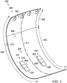
Figure 5 , an illustration of a first layout for a core of a composite fan cowl is depicted in accordance with an illustrative example.Layout 500 may be a physical implementation oflayout 212 ofFigure 2 .Layout 500 ofcore 502 may be a three-dimensional model of a core for a composite fan cowl, such ascore 210 ofcomposite fan cowl 208 ofFigure 2 .Layout 500 may be a three-dimensional model of a core for a composite fan cowl, such as a core forcomposite fan cowl 302 orcomposite fan cowl 304 ofFigure 3 .Layout 500 may be based on bendingmoment intensities 402 ofFigure 4 andexemplary forces 338 ofFigure 3 . -
Layout 500 ofcore 502 includeshinge zone 504,body zone 506, and areas of increasedthickness 508.Body zone 506 is distal to hingezone 504.Hinge zone 504 is abovebody zone 506 alongarc 510 ofcore 502. As depicted,core 502 is symmetric aboutcenterline 512 running in a direction ofarc 510 ofcore 502. -
Hinge zone 504 has a first thickness (not depicted).Body zone 506 has a second thickness (not depicted). Areas of increasedthickness 508 includes two areas having a third thickness (not depicted). Areas of increasedthickness 508 are positioned withinbody zone 506. Areas of increasedthickness 508 provide local stiffening in an area of the highest strain under gust loading. Areas of increasedthickness 508 provide local stiffening in an area of the highest strain under gust loading. Areas of increasedthickness 508 having the third thickness provide local stiffening in an area of highest bending moment on the composite fan cowl. - In this illustrative example, the first thickness and second thickness are different from each other. In this illustrative example, areas of increased
thickness 508 have a greater thickness than the second thickness, and the first thickness and second thickness are in the range of 0.5 inches and 1.5 inches. Each of the first thickness and the second thickness may be selected based on at least one of bendingmoment intensities 402 ofFigure 4 ,exemplary forces 338 ofFigure 3 , or structural or performance requirements for the composite fan cowl. In one non-limiting example, the first thickness is about 0.7 inch while the second thickness is about 1.0 inch. In some illustrative examples, the first thickness is at least 10% less than the second thickness. - Areas of increased
thickness 508 include area of increasedthickness 514 and area of increasedthickness 516. Area of increasedthickness 514 includes ramp up 518,pad 520, and ramp down 522. Area of increasedthickness 516 includes ramp up 524,pad 526, and ramp down 528. Area of increasedthickness 514 and area of increasedthickness 516 may also be referred to as local tapered pads. Area of increasedthickness 514 and area of increasedthickness 516 are positioned at hold open rod (HOR) fittings to decrease deflections. -
Pad 520 and pad 526 have the third thickness. The third thickness is in the range of 1.5 inches to 2.5 inches. In one non-limiting example, the third thickness is about 2 inches. Ramp up 518, ramp down 522, ramp up 524, and ramp down 528 change in thickness alongarc 510 ofcore 502. Ramp up 518 and ramp up 524 change from the second thickness to the third thickness moving frombody zone 506 to pad 520 andpad 526, respectively. Ramp down 522 and ramp down 528 change from the third thickness to the second thickness moving frompad 520 and pad 526 tobody zone 506. -
Core 502 hasarcuate length 530 defined fromhinge zone 504 tobody zone 506. Each ofhinge zone 504 andbody zone 506 have a respective arcuate length.Hinge zone 504 hasarcuate length 532.Body zone 506 hasarcuate length 534. A ratio ofarcuate length 532 ofhinge zone 504 to that ofarcuate length 534 ofbody zone 506 is less than about 1:4. - Turning now to
Figure 6 , an illustration of a second layout for a core of a composite fan cowl is depicted in accordance with an illustrative example.Layout 600 may be a physical implementation oflayout 212 ofFigure 2 without areas of increasedthickness 236.Layout 600 ofcore 602 may be a three-dimensional model of a core for a composite fan cowl, such ascore 210 ofcomposite fan cowl 208 ofFigure 2 .Layout 600 may be a three-dimensional model of a core for a composite fan cowl, such as a core forcomposite fan cowl 302 orcomposite fan cowl 304 ofFigure 3 .Layout 600 may be based on bendingmoment intensities 402 ofFigure 4 andexemplary forces 338 ofFigure 3 . -
Layout 600 ofcore 602 includeshinge zone 604 andbody zone 606.Body zone 606 is distal to hingezone 604.Hinge zone 604 is abovebody zone 606 alongarc 610 ofcore 602. As depicted,core 602 is symmetric aboutcenterline 612 running in a direction ofarc 610 ofcore 602. -
Hinge zone 604 has a first thickness (not depicted).Body zone 606 has a second thickness (not depicted). - In this illustrative example, the first thickness and the second thickness are different from each other. In this illustrative example, the first thickness and the second thickness are in the range of 0.5 inches and 1.5 inches. Each of first thickness and the second thickness may be selected based on at least one of bending
moment intensities 402 ofFigure 4 ,exemplary forces 338 ofFigure 3 , or structural or performance requirements for the composite fan cowl. In one non-limiting example, the first thickness is about 0.7 inch while the second thickness is about 1.0 inch. In some illustrative examples, the first thickness is at least 10% less than the second thickness. -
Core 602 hasarcuate length 614 defined fromhinge zone 604 tobody zone 606. Each ofhinge zone 604 andbody zone 606 have a respective arcuate length.Hinge zone 604 hasarcuate length 616.Body zone 606 hasarcuate length 618. A ratio ofarcuate length 616 ofhinge zone 604 to that ofarcuate length 618 ofbody zone 606 is less than about 1:4. - The different components shown in
Figures 1 and3 -6 may be combined with components inFigure 2 , used with components inFigure 2 , or a combination of the two. Additionally, some of the components inFigures 1 and3 -6 may be illustrative examples of how components shown in block form inFigure 2 can be implemented as physical structures. - Illustrative examples of the present disclosure may be described in the context of aircraft manufacturing and
service method 700 as shown inFigure 7 andaircraft 800 as shown inFigure 8 . Turning first toFigure 7 , an illustration of an aircraft manufacturing and service method is depicted in accordance with an illustrative example. During pre-production, aircraft manufacturing andservice method 700 may include specification anddesign 702 ofaircraft 800 inFigure 8 andmaterial procurement 704. - During production, component and
subassembly manufacturing 706 andsystem integration 708 ofaircraft 800 takes place. Thereafter,aircraft 800 may go through certification anddelivery 710 in order to be placed inservice 712. While inservice 712 by a customer,aircraft 800 is scheduled for routine maintenance andservice 714, which may include modification, reconfiguration, refurbishment, or other maintenance or service. - Each of the processes of aircraft manufacturing and
service method 700 may be performed or carried out by a system integrator, a third party, and/or an operator. In these examples, the operator may be a customer. For the purposes of this description, a system integrator may include, without limitation, any number of aircraft manufacturers and major-system subcontractors; a third party may include, without limitation, any number of vendors, subcontractors, and suppliers; and an operator may be an airline, a leasing company, a military entity, a service organization, and so on. - With reference now to
Figure 8 , an illustration of an aircraft is depicted in which an illustrative example may be implemented. In this example,aircraft 800 is produced by aircraft manufacturing andservice method 700 inFigure 7 and may includeairframe 802 with plurality ofsystems 804 and interior 806. Examples ofsystems 804 include one or more ofpropulsion system 808,electrical system 810,hydraulic system 812, andenvironmental system 814. Any number of other systems may be included. Although an aerospace example is shown, different illustrative examples may be applied to other industries, such as the automotive industry. - Apparatuses and methods embodied herein may be employed during at least one of the stages of aircraft manufacturing and
service method 700. One or more illustrative examples may be used inaircraft 800. One or more illustrative examples may be formed during component andsubassembly manufacturing 706 ofFigure 7 . For example,core 210 ofcomposite fan cowl 208 ofFigure 2 may be formed during component andsubassembly manufacturing 706. Further,core 210 ofcomposite fan cowl 208 ofFigure 2 may be rotated open during maintenance andservice 714 ofFigure 7 . During maintenance andservice 714 ofFigure 7 ,core 210 ofcomposite fan cowl 208 may undergo deformation from a gust of wind. - The illustrative examples show a composite fan cowl with a core having a tailored thickness. Fan cowls may experience large deflections during ground gusts when the airplane is parked and the fan cowls are in the open position. Large deflections are undesirable, since the fan cowl could come into contact with the thrust reverser actuation system (TRAS) or other portions of the engine nacelle.
- A conventional solution to deformation is to increase the core height of the entire composite bond panel. This is a weight prohibitive solution.
- The illustrative examples present a new core height concept to minimize weight and reduce gust deflections. The illustrative examples recognize and take into account that deformation may be reduced by selectively tailoring the core thickness. Local stiffening in the area of the highest strain under gust loading allows for a weight-efficient design.
- In order to implement this core having a tailored thickness, the load distribution and panel's non-linear large deflection response are determined first. The panel presented in the illustrative examples is stiffened near the area of the highest bending moment of the panel.
- There is a benefit from saving weight in an efficient manner. For instance, weight savings may be compared to a change in deformation of the composite fan cowl. The measurement may be described as pounds saved over increase of deformation in inches.
- In some illustrative examples, the core with tailored thickness would decrease the entire panel to heights in the range of 0.7inches to 1 inch, with local tapered pads at the hold open rod (HOR) fittings to decrease deflections. In other illustrative examples, the core with a tailored thickness would decrease the entire core's heights without providing pads.
- By only decreasing core height to within a range of 0.7 inches to 1.0 inch, an amount of weight may be reduced. For example, decreasing the core height only may reduce the weight by about forty pounds. Decreasing the core height also increases the deformation of the fan cowl. Only decreasing the core height may not result in saving weight in a most efficient manner. For example, other approaches may result in a greater measurement of pounds saved per inch increase of deformation. Decreasing the core height may result in approximately 15 pounds saved per inch increase of deformation.
- By decreasing core height to within a range of 0.7 inches to 1.0 inch and including local tapered pads at the hold open rod (HOR) fittings, the weight is decreased from a conventional fan cowl. For example, decreasing the core height with local tapered pads reduces the weight by about 34 pounds. Including local tapered pads with the decreased core height results in a more efficient weight savings, than only decreasing the core height. For example, a reduced core height to within 0.7 inches to 1.0 inch, including local tapered pads, may have about 24 pounds saved per inch increase of deformation. Further, the total deformation of the fan cowl having local tapered pads is less than the deformation of a fan cowl having the same core heights without the local tapered pads. For example, adding pads at the hold open rod fittings produces 1.4 inches of additional deflection versus the baseline.
- This concept is a design of a fan cowl structure that resists gust loads in a weight efficient way. By tailoring the core height of the composite bond panels, over 30 pounds can be removed from each panel. This concept could create a competitive advantage over a similar product by reducing the weight of the engine nacelle. The load distribution and panel's non-linear large deflection response are taken into account in order to implement this solution.
- Further, the disclosure comprises examples according to the following clauses:
- Clause 1. A composite fan cowl connected to hold open rods comprising:
- laminate skins; and
- a core with areas of increased thickness associated with the hold open rods.
- Clause 2. The composite fan cowl of Clause 1, wherein the areas of increased thickness each comprise a ramp up, a pad, and a ramp down in a direction of an arc of the core.
- Clause 3. The composite fan cowl of Clause 2, wherein the core is symmetric about a centerline running in the direction of the arc of the core.
- Clause 4. The composite fan cowl of Clause 2, wherein a thickness of the pad is in a range of 1.5 inches to 2.5 inches.
- Clause 5. The composite fan cowl of Clause 1, wherein the core further comprises a hinge zone and a body zone, each having a respective thickness.
- Clause 6. The composite fan cowl of Clause 5, wherein each respective thickness of the hinge zone and the body zone is in a range of 0.5 inches to 1 inch.
-
Clause 7. The composite fan cowl of Clause 5, wherein a thickness of the hinge zone is less than a thickness of the body zone. - Clause 8. The composite fan cowl of
Clause 7, wherein the areas of increased thickness are positioned within the body zone. - Clause 9. The composite fan cowl of
Clause 7, wherein the core has an arcuate length defined from the hinge zone to the body zone, with each of the hinge zone and the body zone having a respective arcuate length, and wherein a ratio of the arcuate length of the hinge zone to that of the body zone is less than about 1:4. - Clause 10. The composite fan cowl of Clause 1, wherein a thickness of each of the laminate skins is independent of thicknesses of the core.
- Clause 11. The composite fan cowl of Clause 1, wherein a thickness of the areas of increased thickness is selected based on a bending moment of the composite fan cowl when subjected to wind gusts when the composite fan cowl is in an open position.
- Clause 12. A composite fan cowl comprising:
- a core with a hinge zone having a first thickness, a body zone having a second thickness, and two areas of increased thickness including a third thickness, wherein the two areas of increased thickness are positioned within the body zone, wherein the first thickness and second thickness are different from each other, wherein the two areas of increased thickness have a greater thickness than the second thickness, and wherein the first thickness and the second thickness are in a range of 0.5 inches and 1.5 inches.
- Clause 13. The composite fan cowl of Clause 12, wherein the two areas of increased thickness of the core comprise a plurality of ramps.
- Clause 14. The composite fan cowl of Clause 13, wherein the plurality of ramps comprise a ramp up for each of the two areas of increased thickness and a ramp down for each of the two areas of increased thickness, wherein the ramp up for each of the two areas of increased thickness progressively increases thickness from the second thickness to the third thickness, and wherein the ramp down for each of the two areas of increased thickness progressively decreases thickness from the third thickness to the second thickness.
- Clause 15. The composite fan cowl of Clause 14, wherein the ramp up for each of the two areas of increased thickness and the ramp down for each of the two areas of increased thickness change in thickness along an arc of the core, and wherein the ramp up for each of the two areas of increased thickness and the ramp down for each of the two areas of increased thickness are each in a range of about 10 degrees to about 25 degrees.
- Clause 16. The composite fan cowl of Clause 12, wherein the second thickness is greater than the first thickness, and wherein the hinge zone is above the body zone along an arc of the core.
- Clause 17. The composite fan cowl of Clause 12, wherein the third thickness is in the range of 1.5 inches to 2.5 inches.
- Clause 18. The composite fan cowl of Clause 12, wherein the two areas of increased thickness provide local stiffening in an area of highest strain under gust loading.
- Clause 19. The composite fan cowl of Clause 12, wherein the two areas of increased thickness provide local stiffening in an area of highest bending moment on the composite fan cowl.
- Clause 20. An engine nacelle comprising:
- a top portion with hinges; and
- a composite fan cowl pivotally connected to the top portion by the hinges, the composite fan cowl comprising a core with a hinge zone having a first thickness and a body zone having a second thickness, wherein the hinge zone includes the hinges, wherein the body zone is distal from the hinge zone, and wherein the first thickness is less than the second thickness.
- Clause 21. The engine nacelle of Clause 20, wherein the first thickness is at least 10% less than the second thickness, wherein two areas having a third thickness are positioned within the body zone, and wherein the third thickness is greater than the second thickness.
- The description of the different illustrative examples has been presented for purposes of illustration and description, and is not intended to be exhaustive or limited to the examples in the form disclosed. Many modifications and variations will be apparent to those of ordinary skill in the art. Further, different illustrative examples may provide different features as compared to other illustrative examples. The example or examples selected are chosen and described in order to best explain the principles of the examples, the practical application, and to enable others of ordinary skill in the art to understand the disclosure for various examples with various modifications as are suited to the particular use contemplated.
Claims (15)
- A composite fan cowl (208,302,304,404) connected to hold open rods (224,226,228,306,308) comprising:laminate skins (209); anda core (210,502,602) with areas of increased thickness (236,240,248,508,514,516) associated with the hold open rods (224, 226, 228, 306, 308) .
- The composite fan cowl (208,302,304,404) of claim 1, wherein the areas of increased thickness (236,240,248,508,514,516) each comprise a ramp up (242,250,518,524), a pad (252,520,526), and a ramp down (246,254,522,528) in a direction of an arc (233,322) of the core (210,502,602).
- The composite fan cowl (208,302,304,404) of claim 2, wherein the core (210,502,602) is symmetric about a centerline running in the direction of the arc (233,322) of the core (210,502,602).
- The composite fan cowl (208,302,304,404) of any one of claims 1-3, wherein the core (210, 502,602) further comprises a hinge zone (218,408,504,604) and a body zone (232,410,506,606), each having a respective thickness (220,234).
- The composite fan cowl (208,302,304,404) of claim 4, wherein each respective thickness (220,234) of the hinge zone (218,408,504,604) and the body zone (232,410,506,606) is in a range of 0.5 inches to 1 inch.
- The composite fan cowl (208,302,304,404) of claim 4, wherein a thickness (220) of the hinge zone (218,408,504,604) is less than a thickness (234) of the body zone (232,410,506,606).
- The composite fan cowl (208,302,304,404) of claim 6, wherein the areas of increased thickness (236,240,248,508,514,516) are positioned within the body zone (232,410,506,606).
- The composite fan cowl (208,302,304,404) of claim 6, wherein the core (210, 502,602) has an arcuate length (264,530,614) defined from the hinge zone (218,408,504,604) to the body zone (232,410,506,606), with each of the hinge zone (218,408,504,604) and the body zone (232,410,506,606) having a respective arcuate length (266,532,616,268,534,618), and wherein a ratio of the arcuate length (266,532,616) of the hinge zone (218,408,504,604) to that of the body zone (232,410,506,606) is less than about 1:4.
- A composite fan cowl (208,302,304,404) comprising:a core (210,502,602) with a hinge zone (218,408,504,604) having a first thickness (220), a body zone (232,410,506,606) having a second thickness (234), and two areas of increased thickness including a third thickness (256), wherein the two areas of increased thickness are positioned within the body zone (232,410,506,606), wherein the first thickness (220) and second thickness (234) are different from each other, wherein the two areas of increased thickness have a greater thickness than the second thickness (234), and wherein the first thickness (220) and the second thickness (234) are in a range of 0.5 inches and 1.5 inches.
- The composite fan cowl (208,302,304,404) of claim 9, wherein the two areas of increased thickness of the core (210, 502,602) comprise a plurality of ramps.
- The composite fan cowl (208,302,304,404) of claim 10, wherein the plurality of ramps comprise a ramp up (242,250,518,524) for each of the two areas of increased thickness and a ramp down (246,254,522,528) for each of the two areas of increased thickness, wherein the ramp up (242,250,518,524) for each of the two areas of increased thickness progressively increases thickness from the second thickness (234) to the third thickness (256), and wherein the ramp down (246,254,522,528) for each of the two areas of increased thickness progressively decreases thickness from the third thickness (256) to the second thickness (234).
- The composite fan cowl (208,302,304,404) of claim 11, wherein the ramp up (242,250,518,524) for each of the two areas of increased thickness and the ramp down (246,254,522,528) for each of the two areas of increased thickness change in thickness along an arc (233,322) of the core (210, 502,602), and wherein the ramp up (242,250,518,524) for each of the two areas of increased thickness and the ramp down (246,254,522,528) for each of the two areas of increased thickness are each in a range of about 10 degrees to about 25 degrees.
- The composite fan cowl (208,302,304,404) of any one of claims 9-12, wherein the second thickness (234) is greater than the first thickness (220), and wherein the hinge zone (218,408,504,604) is above the body zone (232,410,506,606) along an arc (233,322) of the core (210, 502,602).
- An engine nacelle (202,300) comprising:a top portion (216,301) with hinges (214); anda composite fan cowl (208,302,304,404) pivotally connected to the top portion (216,301) by the hinges (214), the composite fan cowl (208,302,304,404) comprising a core (210, 502,602) with a hinge zone (218,408,504,604) having a first thickness (220) and a body zone (232,410,506,606) having a second thickness (234), wherein the hinge zone (218,408,504,604) includes the hinges (214), wherein the body zone (232,410,506,606) is distal from the hinge zone (218,408,504,604), and wherein the first thickness (220) is less than the second thickness (234).
- The engine nacelle (202,300) of claim 14, wherein the first thickness (220) is at least 10% less than the second thickness (234), wherein two areas having a third thickness (256) are positioned within the body zone (232,410,506,606), and wherein the third thickness (256) is greater than the second thickness (234) .
Applications Claiming Priority (1)
| Application Number | Priority Date | Filing Date | Title |
|---|---|---|---|
| US15/369,195 US10479517B2 (en) | 2016-12-05 | 2016-12-05 | Composite fan cowl with a core having tailored thickness |
Publications (1)
| Publication Number | Publication Date |
|---|---|
| EP3360784A1 true EP3360784A1 (en) | 2018-08-15 |
Family
ID=62242930
Family Applications (1)
| Application Number | Title | Priority Date | Filing Date |
|---|---|---|---|
| EP17194463.0A Pending EP3360784A1 (en) | 2016-12-05 | 2017-10-02 | Composite fan cowl with a core having tailored thickness |
Country Status (3)
| Country | Link |
|---|---|
| US (1) | US10479517B2 (en) |
| EP (1) | EP3360784A1 (en) |
| CN (1) | CN108146641B (en) |
Families Citing this family (5)
| Publication number | Priority date | Publication date | Assignee | Title |
|---|---|---|---|---|
| US11473527B2 (en) * | 2016-09-28 | 2022-10-18 | The Boeing Company | Nacelle with tangential restraint |
| US11125157B2 (en) | 2017-09-22 | 2021-09-21 | The Boeing Company | Advanced inlet design |
| US11242866B2 (en) * | 2018-08-01 | 2022-02-08 | General Electric Company | Casing having a non-axisymmetric composite wall |
| US11535390B2 (en) * | 2020-02-28 | 2022-12-27 | Rohr, Inc. | Structural panel with integrated coupler |
| BR102022003769A2 (en) | 2021-05-04 | 2022-11-16 | The Boeing Company | NACELE ENTRY STRUCTURE OF AN ENGINE ASSEMBLY |
Citations (3)
| Publication number | Priority date | Publication date | Assignee | Title |
|---|---|---|---|---|
| WO2001058680A1 (en) * | 2000-02-11 | 2001-08-16 | Bae Systems Plc | A method of reinforcing a laminated member such as a skin for an aircraft |
| US6375121B1 (en) * | 1997-11-26 | 2002-04-23 | Aerospatiale Societe Nationale Industrielle | Method for making a composite panel and resulting panel |
| EP3000734A1 (en) * | 2014-09-29 | 2016-03-30 | Airbus Defence and Space, S.A. | Alignment and safety device for the cowls of aircraft engine nacelles |
Family Cites Families (9)
| Publication number | Priority date | Publication date | Assignee | Title |
|---|---|---|---|---|
| DE3374546D1 (en) * | 1983-12-19 | 1987-12-23 | Boeing Co | Apparatus and method for minimizing engine backbone bending |
| AT7743U1 (en) * | 2004-07-20 | 2005-08-25 | Magna Steyr Fahrzeugtechnik Ag | BONNET OF COMPOSITE MATERIAL |
| FR2920143B1 (en) * | 2007-08-20 | 2010-01-22 | Aircelle Sa | DEVICE FOR CONTROLLING HOUSING MAINTENANCE ACTUATORS OF A TURBOREACTOR NACELLE |
| FR2960855A1 (en) * | 2010-06-03 | 2011-12-09 | Aircelle Sa | NACELLE FOR TURBOJETACTOR WITH DEVICE FOR RECOVERING CIRCUMFERENTIAL EFFORTS |
| FR2961788B1 (en) * | 2010-06-29 | 2012-06-15 | Aircelle Sa | TURBOREACTOR NACELLE |
| US8491042B2 (en) * | 2010-09-07 | 2013-07-23 | Ford Global Technologies, Llc | Energy-absorbing cowl structure |
| CN202130570U (en) * | 2011-05-16 | 2012-02-01 | 湖北航天技术研究院总体设计所 | Aircraft cowling shell |
| ES2635122T3 (en) * | 2013-03-04 | 2017-10-02 | Airbus Defence And Space Sa | Improved monolithic hood of an aircraft engine and manufacturing method |
| CN105270641B (en) * | 2015-10-10 | 2018-01-16 | 中航飞机股份有限公司西安飞机分公司 | The plug-in auxiliary fuel tank leading edge structure of aircraft that a kind of anti-bird is hit |
-
2016
- 2016-12-05 US US15/369,195 patent/US10479517B2/en active Active
-
2017
- 2017-10-02 EP EP17194463.0A patent/EP3360784A1/en active Pending
- 2017-11-03 CN CN201711069030.8A patent/CN108146641B/en active Active
Patent Citations (3)
| Publication number | Priority date | Publication date | Assignee | Title |
|---|---|---|---|---|
| US6375121B1 (en) * | 1997-11-26 | 2002-04-23 | Aerospatiale Societe Nationale Industrielle | Method for making a composite panel and resulting panel |
| WO2001058680A1 (en) * | 2000-02-11 | 2001-08-16 | Bae Systems Plc | A method of reinforcing a laminated member such as a skin for an aircraft |
| EP3000734A1 (en) * | 2014-09-29 | 2016-03-30 | Airbus Defence and Space, S.A. | Alignment and safety device for the cowls of aircraft engine nacelles |
Also Published As
| Publication number | Publication date |
|---|---|
| CN108146641B (en) | 2023-08-04 |
| US10479517B2 (en) | 2019-11-19 |
| CN108146641A (en) | 2018-06-12 |
| US20180155042A1 (en) | 2018-06-07 |
Similar Documents
| Publication | Publication Date | Title |
|---|---|---|
| EP3360784A1 (en) | Composite fan cowl with a core having tailored thickness | |
| EP2571757B1 (en) | Composite stringer end trim | |
| US8973871B2 (en) | Box structures for carrying loads and methods of making the same | |
| Herrmann et al. | Sandwich structures technology in commercial aviation | |
| AU2017218981B2 (en) | Aircraft wings, aircraft, and related methods | |
| CA2842408C (en) | Continuously curved spar and method of manufacturing | |
| CA3035269C (en) | Wing flap with torque member and method for forming thereof | |
| WO2014158295A2 (en) | High-wing-aircraft fuselage support structure | |
| EP3546344B1 (en) | Wing flap with torque member and method for forming thereof | |
| CN109080813B (en) | Wing-to-fuselage junction and aircraft including the same | |
| EP3446967B1 (en) | Cable-free and strut-free fairing for supporting a person | |
| AU2014200142A1 (en) | Box structures for carrying loads and methods of making the same | |
| Garre et al. | Modeling and analysis of a RIBS and Spars of an airplane wing for bending and shear loads | |
| US10625872B2 (en) | Composite fan cowl having core with varying thickness | |
| Striz et al. | Multidisciplinary optimization of a transport aircraft wing | |
| Edi | Investigation of the application of hybrid laminar flow control and variable camber wing design for regional aircraft | |
| EP4685048A1 (en) | A structural panel with carbon composite plies | |
| Pearce | Evaluation of laminar flow control systems concepts for subsonic commercial transport aircraft | |
| Bakshi et al. | Damage tolerance analysis of wing fuselage interface in BWB aircraft design | |
| CN102642610A (en) | Murphy private jet | |
| Rossi et al. | Design and analysis of a composite fuselage | |
| Smith | U‐99 uninhabited tactical aircraft preliminary structural design | |
| Watson | Preliminary design development AV-8B forward fuselage composite structure | |
| Khaleel | Comparison in Simulation of Different Joints Used in Aircraft | |
| Usuki et al. | The conceptual study of supersonic transport structure |
Legal Events
| Date | Code | Title | Description |
|---|---|---|---|
| PUAI | Public reference made under article 153(3) epc to a published international application that has entered the european phase |
Free format text: ORIGINAL CODE: 0009012 |
|
| STAA | Information on the status of an ep patent application or granted ep patent |
Free format text: STATUS: REQUEST FOR EXAMINATION WAS MADE |
|
| 17P | Request for examination filed |
Effective date: 20171002 |
|
| AK | Designated contracting states |
Kind code of ref document: A1 Designated state(s): AL AT BE BG CH CY CZ DE DK EE ES FI FR GB GR HR HU IE IS IT LI LT LU LV MC MK MT NL NO PL PT RO RS SE SI SK SM TR |
|
| AX | Request for extension of the european patent |
Extension state: BA ME |
|
| RBV | Designated contracting states (corrected) |
Designated state(s): AL AT BE BG CH CY CZ DE DK EE ES FI FR GB GR HR HU IE IS IT LI LT LU LV MC MK MT NL NO PL PT RO RS SE SI SK SM TR |
|
| RAP3 | Party data changed (applicant data changed or rights of an application transferred) |
Owner name: THE BOEING COMPANY |
|
| STAA | Information on the status of an ep patent application or granted ep patent |
Free format text: STATUS: EXAMINATION IS IN PROGRESS |
|
| 17Q | First examination report despatched |
Effective date: 20250509 |