EP3360690A1 - Printer - Google Patents
Printer Download PDFInfo
- Publication number
- EP3360690A1 EP3360690A1 EP17206540.1A EP17206540A EP3360690A1 EP 3360690 A1 EP3360690 A1 EP 3360690A1 EP 17206540 A EP17206540 A EP 17206540A EP 3360690 A1 EP3360690 A1 EP 3360690A1
- Authority
- EP
- European Patent Office
- Prior art keywords
- rotating member
- projection
- battery
- printer
- recess
- Prior art date
- Legal status (The legal status is an assumption and is not a legal conclusion. Google has not performed a legal analysis and makes no representation as to the accuracy of the status listed.)
- Withdrawn
Links
Images


Classifications
-
- B—PERFORMING OPERATIONS; TRANSPORTING
- B41—PRINTING; LINING MACHINES; TYPEWRITERS; STAMPS
- B41J—TYPEWRITERS; SELECTIVE PRINTING MECHANISMS, i.e. MECHANISMS PRINTING OTHERWISE THAN FROM A FORME; CORRECTION OF TYPOGRAPHICAL ERRORS
- B41J29/00—Details of, or accessories for, typewriters or selective printing mechanisms not otherwise provided for
- B41J29/02—Framework
-
- B—PERFORMING OPERATIONS; TRANSPORTING
- B41—PRINTING; LINING MACHINES; TYPEWRITERS; STAMPS
- B41J—TYPEWRITERS; SELECTIVE PRINTING MECHANISMS, i.e. MECHANISMS PRINTING OTHERWISE THAN FROM A FORME; CORRECTION OF TYPOGRAPHICAL ERRORS
- B41J3/00—Typewriters or selective printing or marking mechanisms characterised by the purpose for which they are constructed
-
- B—PERFORMING OPERATIONS; TRANSPORTING
- B41—PRINTING; LINING MACHINES; TYPEWRITERS; STAMPS
- B41J—TYPEWRITERS; SELECTIVE PRINTING MECHANISMS, i.e. MECHANISMS PRINTING OTHERWISE THAN FROM A FORME; CORRECTION OF TYPOGRAPHICAL ERRORS
- B41J29/00—Details of, or accessories for, typewriters or selective printing mechanisms not otherwise provided for
- B41J29/02—Framework
- B41J29/023—Framework with reduced dimensions
-
- B—PERFORMING OPERATIONS; TRANSPORTING
- B41—PRINTING; LINING MACHINES; TYPEWRITERS; STAMPS
- B41J—TYPEWRITERS; SELECTIVE PRINTING MECHANISMS, i.e. MECHANISMS PRINTING OTHERWISE THAN FROM A FORME; CORRECTION OF TYPOGRAPHICAL ERRORS
- B41J29/00—Details of, or accessories for, typewriters or selective printing mechanisms not otherwise provided for
- B41J29/38—Drives, motors, controls or automatic cut-off devices for the entire printing mechanism
- B41J29/393—Devices for controlling or analysing the entire machine ; Controlling or analysing mechanical parameters involving printing of test patterns
-
- B—PERFORMING OPERATIONS; TRANSPORTING
- B41—PRINTING; LINING MACHINES; TYPEWRITERS; STAMPS
- B41J—TYPEWRITERS; SELECTIVE PRINTING MECHANISMS, i.e. MECHANISMS PRINTING OTHERWISE THAN FROM A FORME; CORRECTION OF TYPOGRAPHICAL ERRORS
- B41J29/00—Details of, or accessories for, typewriters or selective printing mechanisms not otherwise provided for
-
- B—PERFORMING OPERATIONS; TRANSPORTING
- B41—PRINTING; LINING MACHINES; TYPEWRITERS; STAMPS
- B41J—TYPEWRITERS; SELECTIVE PRINTING MECHANISMS, i.e. MECHANISMS PRINTING OTHERWISE THAN FROM A FORME; CORRECTION OF TYPOGRAPHICAL ERRORS
- B41J29/00—Details of, or accessories for, typewriters or selective printing mechanisms not otherwise provided for
- B41J29/12—Guards, shields or dust excluders
- B41J29/13—Cases or covers
-
- B—PERFORMING OPERATIONS; TRANSPORTING
- B41—PRINTING; LINING MACHINES; TYPEWRITERS; STAMPS
- B41J—TYPEWRITERS; SELECTIVE PRINTING MECHANISMS, i.e. MECHANISMS PRINTING OTHERWISE THAN FROM A FORME; CORRECTION OF TYPOGRAPHICAL ERRORS
- B41J3/00—Typewriters or selective printing or marking mechanisms characterised by the purpose for which they are constructed
- B41J3/36—Typewriters or selective printing or marking mechanisms characterised by the purpose for which they are constructed for portability, i.e. hand-held printers or laptop printers
-
- B—PERFORMING OPERATIONS; TRANSPORTING
- B41—PRINTING; LINING MACHINES; TYPEWRITERS; STAMPS
- B41J—TYPEWRITERS; SELECTIVE PRINTING MECHANISMS, i.e. MECHANISMS PRINTING OTHERWISE THAN FROM A FORME; CORRECTION OF TYPOGRAPHICAL ERRORS
- B41J29/00—Details of, or accessories for, typewriters or selective printing mechanisms not otherwise provided for
- B41J29/38—Drives, motors, controls or automatic cut-off devices for the entire printing mechanism
- B41J29/393—Devices for controlling or analysing the entire machine ; Controlling or analysing mechanical parameters involving printing of test patterns
- B41J2029/3932—Battery or power source mounted on the carriage
Definitions
- the present disclosure relates to a printer.
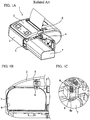
- FIG. 1A is a perspective view of a printer.
- FIG. 1B is a schematic configuration diagram of a battery storing part.
- FIG. 1C is a configuration diagram of a battery lock.
- a printer 1 of FIG. 1 is a mobile printer, and includes a housing 2, an upper cover 3, a battery cover 4, a storing part 5 and a battery lock 6.
- the battery cover 4 is rotatably fixed to a side surface of the housing 2.
- the storing part 5 is a space in which the battery 7 is stored.
- the battery lock 6 includes a taper 6a as illustrated in FIG. 1C .
- the battery lock 6 is fixed to one end of a spring 8, and the other end of the spring 8 is fixed to a back surface of the upper cover 3.
- the spring 8 biases the battery lock 6 downward in FIG. 1B .
- the taper 6a protrudes toward the storing part 5.
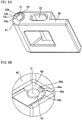
- FIG. 2A is a perspective view of another printer.
- FIG. 2B is a perspective view of the another printer in a state of removing the battery cover.
- FIG. 2C is a perspective view of the another printer of FIG. 2B in an overturned state.
- Patent Document 1 Japanese Laid-open Patent Publication No. 2009-190413 .
- a printer 11 of FIG. 2A includes a housing 12, an operation part 13 and a battery cover 14. When the battery cover 14 is removed, a storing part 15 is exposed as illustrated in FIG. 2B .
- a through-hole 16 is formed on a bottom surface of the housing 12.
- the printer 11 includes a holding member 18 illustrated in FIG. 2C .
- the holding member 18 is attached to the bottom surface of the housing 12, and can be removed from the bottom surface of the housing 12 in an A direction illustrated in FIG. 2C .
- a projection 17 having a substantially trapezoidal shape illustrated in FIG. 2B is formed on the holding member 18.
- a printer (21) including: a housing (22); a rotating member (30) that is rotatably fixed to the housing; a fixing part (40) that is formed on the housing, and rotatably supports a rotary shaft (33) of the rotating member; wherein one of the fixing part and the rotating member includes a projection (38, 42) formed around the rotary shaft and capable of contacting the other of the fixing part and the rotating member, and the other of the fixing part and the rotating member includes a recess (43, 51) that is formed around the rotary shaft and does not contact the projection, a flat part (44, 52) that is formed around the rotary shaft and allows the rotation of the rotating member while contacting the projection, and a regulating part (45, 53) that is formed around the rotary shaft, contacts the projection and regulates the rotation of the rotating member.
- FIG. 3A is a perspective view of a printer according to a present embodiment.
- FIG. 3B is a perspective view of the printer when a battery cover is half-opened.
- FIG. 3C is a diagram illustrating a state where a battery contacts the battery cover.
- a front and rear direction, a right and left direction, and an up and down direction are defined as illustrated in FIG. 3A , for convenience.
- a printer 21 illustrated in FIG. 3A includes a housing 22, a cover 23, an open lever 24, an operation panel 25, a battery cover 26 and a lock lever 27.
- the cover 23 covers a rolled paper stored in the printer 21, is openably/closably fixed to the housing 22, and can be opened in an A direction when the open lever 24 is depressed.
- the lock lever 27 is fixed to the battery cover 26 to be slid up and down. When the lock lever 27 is moved downward, the battery cover 26 can be opened as illustrated in FIG. 3B . When the lock lever 27 is moved upward, the battery cover 26 can be fixed to the housing 22 in a closed state. The battery cover 26 is opened and closed in a B direction as illustrated in FIG. 3B .
- a storing part 28 for storing a battery 29 appears.
- the battery 29 contacts the battery cover 26 as illustrated in a domain C of FIG. 3C , which makes it possible to prevent the falling of the battery 29.
- FIG. 4A is a perspective view of the printer 21 when the battery cover 26 is fully opened.
- FIG. 4B is a configuration diagram of a back surface of the battery cover 26.
- a convex part 27a is formed on an upper end of the lock lever 27.
- the convex part 27a engages with a part of a side surface of the housing 22 located above the storing part 28. Thereby, the battery cover 26 is fixed to the side surface of the housing 22.
- a groove 37 into which a shaft 35 is inserted and stoppers 36 fixing the shaft 35 are formed on the back surface of the battery cover 26.
- Fixing parts 40 for rotatably fixing a rotating member 30 are fixed on the side surface of the housing 22 as illustrated in FIG. 4A .
- the rotating member 30 includes a through-hole 31 into which a shaft 33 is inserted, and a long through-hole 32 into which the shaft 35 is inserted and that movably supports the shaft 35 in the right and left direction of FIG. 4A .
- Both ends of the shaft 33 inserted into the through-hole 31 are fixed to the fixing parts 40.
- the rotating member 30 is rotatably fixed to the fixing parts 40.
- Both ends of the shaft 35 inserted into the long through-hole 32 are fixed to the back surface of the battery cover 26 by the groove 37 and the stoppers 36. Since the shaft 35 is movable within the long through-hole 32 in the right and left direction, the battery cover 26 to which the shaft 35 is attached is fixed to the rotating member 30 to be movable in the right and left direction of FIG. 4B .
- FIG. 5A is a configuration diagram of the fixing part 40.
- FIG. 5B is a configuration diagram of the rotating member 30.
- FIG. 5C is a schematic diagram illustrating an engagement state of the fixing part 40 and the rotating member 30.
- a hole 41 into which the shaft 33 is inserted and a projection 42 that can contact the rotating member 30 are formed on a surface of the fixing part 40 opposite to the rotating member 30, as illustrated in FIG. 5A .
- an upper fixing part 40 is provided with the hole 41 and the projection 42.
- a lower fixing part 40 also is provided with the hole 41. At least one of the upper fixing part 40 and the lower fixing part 40 may be provided with the projection 42.
- a recess 51 that does not contact the projection 42
- a flat part 52 that allows the rotation of the rotating member 30 while contacting the projection 42
- a regulating part 53 that contacts the projection 42 and regulates the rotation of the rotating member 30, as illustrated in FIG. 5B .
- the recess 51 is dug from the flat part 52 and is formed at a position lower than the flat part 52.
- the regulating part 53 is formed to protrude vertically from the flat part 52.
- a coupling surface 54 between the recess 51 and the flat part 52 is inclined so that the projection 42 is easy to move from the recess 51 to the flat part 52.
- the projection 42 When the projection 42 is located in the recess 51 as illustrated in a left drawing of FIG. 5C , the projection 42 does not contact the recess 51, and therefore the rotating member 30 rotates smoothly. At this time, the battery cover 26 is half-opened. When the projection 42 reaches the coupling surface 54, the opening operation of the rotating member 30 and the battery cover 26 is stopped once. Since the movement in a D direction (a pushing direction of the battery 29) of the battery 29 to be pushed by a battery terminal in the printer 21 is inhibited by the rotating member 30, it is possible to prevent the falling of the battery 29.
- a D direction a pushing direction of the battery 29
- the projection 42 When the projection 42 reaches the coupling surface 54 and further a user pushes the rotating member 30 or the battery cover 26 in a fully open direction E, the projection 42 enters the flat part 52 beyond the coupling surface 54 as illustrated in a right drawing of FIG. 5C . Although the projection 42 contacts the flat part 52, the rotating member 30 can rotate by a pushing force. When the projection 42 reaches one end of the regulating part 53, the rotation of the rotating member 30 is stopped. At this time, since the battery cover 26 is fully opened, it is possible to take out the battery 29.
- FIG. 6A is a diagram illustrating a first variation of the rotating member 30.
- FIG. 6B is a perspective view of the printer 21 to which the rotating member 30 of the first variation is attached.
- FIG. 6C is a diagram illustrating a variation of the recess 51 of the rotating member 30.
- a projection 55 for preventing the falling of the battery may be formed on a surface 56 of the rotating member 30 opposite to the battery 29 when the battery cover 26 is closed as illustrated in FIG. 6A .
- the projection 55 is formed at another end opposite to one end of the rotation member 30 on which the through-hole 31 is formed.
- the shape of the projection 55 is not limited to the shape illustrated in FIG. 6A .
- the battery cover 26 is half-opened, the battery 29 contacts the projection 55 and it is therefore possible to prevent the falling of the battery 29.
- a recess or irregularity may be formed on the surface 56 of the rotating member 30 as substitute for the projection 55.
- the projection 55 is formed on the surface 56 of the rotating member 30.
- a tape having a large frictional resistance may be pasted on the surface 56, or surface treatment of irregularity may be performed on the surface 56.
- the position and the size of the recess 51 of the rotating member 30 may be changed as illustrated in FIG. 6C .
- a width of the recess 51 is narrower than that of the recess 51 of the left drawing of FIG. 6C .
- FIG. 7A is a diagram illustrating a second variation of the rotating member 30.
- FIG. 7B is a diagram illustrating a first variation of the fixing part 40.
- the fixing part 40 includes the projection 42, and the rotating member 30 includes the recess 51, the flat part 52 and the regulating part 53.
- the rotating member 30 may include a projection 38, and the fixing part 40 may include a recess 43, a flat part 44 and a regulating part 45, as illustrated in FIG. 7A and 7B .
- the projection 38 that can contact the fixing part 40 is formed on an outer circumference part of the through-hole 31 and an upper surface of the rotating member 30, as illustrated in FIG. 7A . It is sufficient that at least one of the upper surface and the bottom surface of the rotating member 30 has the projection 38.
- FIG. 7B Formed around the hole 41 of the fixing parts 40 opposite to the rotating member 30 are the recess 43 that does not contact the projection 38, the flat part 44 that allows the rotation of the rotating member 30 while contacting the projection 38, and the regulating part 45 that contacts the projection 38 and regulates the rotation of the rotating member 30, as illustrated in FIG. 7B .
- the recess 43 is dug from the flat part 44 and is formed at a position higher than the flat part 44.
- the regulating part 45 is formed to protrude vertically from the flat part 44.
- a coupling surface 46 between the recess 43 and the flat part 44 is inclined so that the projection 38 is easy to move from the recess 43 to the flat part 44.
- FIG. 7B illustrates the configuration of the upper fixing part 40, but the lower fixing part 40 may include the recess 43, the flat part 44 and the regulating part 45.
- the projection 38 When the projection 38 is located in the recess 43 and the projection 38 does not contact the recess 43, and therefore the rotating member 30 rotates smoothly.
- the projection 38 reaches the coupling surface 46, the opening operation of the rotating member 30 and the battery cover 26 is stopped once. At this time, since the battery cover 26 is half-opened, it is possible to prevent the falling of the battery 29.
- the projection 38 When the projection 38 reaches the coupling surface 46 and further the user pushes the rotating member 30 or the battery cover 26 in the fully open direction, the projection 38 enters the flat part 44 beyond the coupling surface 46. Although the projection 38 contacts the flat part 44, the rotating member 30 can rotate by the pushing force.
- the projection 38 reaches one end of the regulating part 45, the rotation of the rotating member 30 is stopped. At this time, since the battery cover 26 is fully opened, it is possible to take out the battery 29.
- FIG. 8A is a diagram illustrating a third variation of the rotating member 30.
- FIG. 8B is a diagram illustrating a second variation of the fixing part 40.
- the recess 51 is dug from the first flat part 52a and is formed at a position lower than the first flat part 52a.
- the first flat part 52a is dug from the second flat part 52b and is formed at a position lower than the second flat part 52b.
- the regulating part 53 is formed to protrude vertically from the second flat part 52b.
- a coupling surface 54a between the recess 51 and the first flat part 52a is inclined so that the projection 42 is easy to move from the recess 51 to the first flat part 52a.
- a coupling surface 54b between the first flat part 52a and the second flat part 52b is inclined so that the projection 42 is easy to move from the first flat part 52a to the second flat part 52b.
- the rotating member 30 includes the plurality of flat parts 52a and 52b that allow the rotation of the rotating member 30 while contacting the projection 42, and thereby the opening angle of the battery cover 26 at the time of the half opening of the battery cover 26 may be adjusted.
- the recess 43 is dug from the first flat part 44a and is formed at a position higher than the first flat part 44a.
- the first flat part 44a is dug from the second flat part 44b and is formed at a position higher than the second flat part 44b.
- the regulating part 45 is formed to protrude vertically from the second flat part 44b.
- a coupling surface 46a between the recess 43 and the first flat part 44a is inclined so that the projection 38 is easy to move from the recess 43 to the first flat part 44a.
- a coupling surface 46b between the first flat part 44a and the second flat part 44b is inclined so that the projection 38 is easy to move from the first flat part 44a to the second flat part 44b.
- the fixing part 40 includes the plurality of flat parts 44a and 44b that allow the rotation of the rotating member 30 while contacting the projection 38, and thereby the opening angle of the battery cover 26 at the time of the half opening of the battery cover 26 may be adjusted.
- the rotating member 30 that contributes to the opening and closing of the battery cover 26 contacts the projection 42 of the fixing part 40 and once stops the opening operation in a half-open state of the battery cover 26. Therefore, it is possible to prevent the falling of the battery 29. Thereby, the printer 21 does not have to include a dedicated part to prevent the falling of the battery 29.
Landscapes
- Printers Characterized By Their Purpose (AREA)
- Accessory Devices And Overall Control Thereof (AREA)
- Battery Mounting, Suspending (AREA)
Abstract
Description
- The present disclosure relates to a printer.
-
FIG. 1A is a perspective view of a printer.FIG. 1B is a schematic configuration diagram of a battery storing part.FIG. 1C is a configuration diagram of a battery lock. - A printer 1 of
FIG. 1 is a mobile printer, and includes ahousing 2, anupper cover 3, abattery cover 4, astoring part 5 and abattery lock 6. Thebattery cover 4 is rotatably fixed to a side surface of thehousing 2. The storingpart 5 is a space in which thebattery 7 is stored. Thebattery lock 6 includes ataper 6a as illustrated inFIG. 1C . Thebattery lock 6 is fixed to one end of aspring 8, and the other end of thespring 8 is fixed to a back surface of theupper cover 3. Thespring 8 biases the battery lock 6 downward inFIG. 1B . Thereby, thetaper 6a protrudes toward thestoring part 5. - When a
battery 7 is inserted into thestoring part 5, a user pushes thebattery 7 toward thestoring part 5. At this time, thebattery 7 contacts thetaper 6a and thebattery lock 6 moves upward inFIG. 1B , and therefore thebattery 7 can be inserted into thestoring part 5. When thebattery 7 is completely inserted into thestoring part 5, thebattery lock 6 is biased by thespring 8 and thetaper 6a protrudes toward thestoring part 5. Thereby, thebattery 7 is held in thestoring part 5, which makes it possible to prevent the falling of thebattery 7. - FG. 2A is a perspective view of another printer.
FIG. 2B is a perspective view of the another printer in a state of removing the battery cover.FIG. 2C is a perspective view of the another printer ofFIG. 2B in an overturned state. The another printer ofFIGs. 2A to 2C is described in Patent Document 1 (Japanese Laid-open Patent Publication No.2009-190413 - A
printer 11 ofFIG. 2A includes ahousing 12, anoperation part 13 and abattery cover 14. When thebattery cover 14 is removed, astoring part 15 is exposed as illustrated inFIG. 2B . A through-hole 16 is formed on a bottom surface of thehousing 12. - Moreover, the
printer 11 includes aholding member 18 illustrated inFIG. 2C . Theholding member 18 is attached to the bottom surface of thehousing 12, and can be removed from the bottom surface of thehousing 12 in an A direction illustrated inFIG. 2C . Aprojection 17 having a substantially trapezoidal shape illustrated inFIG. 2B is formed on theholding member 18. When theholding member 18 is attached to the bottom surface of thehousing 12, theprojection 17 is inserted into the through-hole 16 and appears in thestoring part 15 as illustrated inFIG. 2B , it is possible to prevent the falling of abattery 10. - In the above-mentioned printer 1, in order to prevent the falling of the
battery 7, it is necessary to provide thebattery lock 6 and thespring 8, and therefore the number of parts is increased. When the miniaturization of the printer 1 is required, there is a possibility that thebattery lock 6 and thespring 8 cannot be mounted in the printer 1. - In the above-mentioned
printer 11, in order to prevent the falling of thebattery 10, it is necessary to provide theholding member 18, and therefore the number of parts is increased. Moreover, when thebattery 10 is attached and detached, theholding member 18 also must be removed from thehousing 12 or attached to thehousing 12, and therefore there is a problem that the operability of attachment and detachment of thebattery 10 is poor. - It is desirable to provide a printer that can prevent the falling of a battery without adding parts for preventing the falling of the battery.
- According to an aspect of an embodiment, there is provided a printer (21) including: a housing (22); a rotating member (30) that is rotatably fixed to the housing; a fixing part (40) that is formed on the housing, and rotatably supports a rotary shaft (33) of the rotating member; wherein one of the fixing part and the rotating member includes a projection (38, 42) formed around the rotary shaft and capable of contacting the other of the fixing part and the rotating member, and the other of the fixing part and the rotating member includes a recess (43, 51) that is formed around the rotary shaft and does not contact the projection, a flat part (44, 52) that is formed around the rotary shaft and allows the rotation of the rotating member while contacting the projection, and a regulating part (45, 53) that is formed around the rotary shaft, contacts the projection and regulates the rotation of the rotating member.
- The invention is described, by way of example only, with reference to the figures, in which:
-
FIG. 1A is a perspective view of a printer; -
FIG. 1B is a schematic configuration diagram of a battery storing part; -
FIG. 1C is a configuration diagram of a battery lock; - FG. 2A is a perspective view of another printer;
-
FIG. 2B is a perspective view of the another printer in a state of removing the battery cover; -
FIG. 2C is a perspective view of the another printer ofFIG. 2B in an overturned state; -
FIG. 3A is a perspective view of a printer according to a present embodiment; -
FIG. 3B is a perspective view of the printer when a battery cover is half-opened; -
FIG. 3C is a diagram illustrating a state where a battery contacts the battery cover; -
FIG. 4A is a perspective view of the printer when the battery cover is fully opened; -
FIG. 4B is a configuration diagram of a back surface of the battery cover; -
FIG. 5A is a configuration diagram of a fixing part; -
FIG. 5B is a configuration diagram of a rotating member; -
FIG. 5C is a schematic diagram illustrating an engagement state of the fixing part and the rotating member; -
FIG. 6A is a diagram illustrating a first variation of the rotating member; -
FIG. 6B is a perspective view of the printer to which the rotating member of the first variation is attached; -
FIG. 6C is a diagram illustrating a variation of a recess of the rotating member; -
FIG. 7A is a diagram illustrating a second variation of the rotating member; -
FIG. 7B is a diagram illustrating a first variation of the fixing part; -
FIG. 8A is a diagram illustrating a third variation of the rotating member; and -
FIG. 8B is a diagram illustrating a second variation of the fixing part. - A description will now be given of an embodiment with reference to drawings.
-
FIG. 3A is a perspective view of a printer according to a present embodiment.FIG. 3B is a perspective view of the printer when a battery cover is half-opened.FIG. 3C is a diagram illustrating a state where a battery contacts the battery cover. Hereinafter, a front and rear direction, a right and left direction, and an up and down direction are defined as illustrated inFIG. 3A , for convenience. - A
printer 21 illustrated inFIG. 3A includes ahousing 22, acover 23, anopen lever 24, anoperation panel 25, abattery cover 26 and alock lever 27. Thecover 23 covers a rolled paper stored in theprinter 21, is openably/closably fixed to thehousing 22, and can be opened in an A direction when theopen lever 24 is depressed. Thelock lever 27 is fixed to thebattery cover 26 to be slid up and down. When thelock lever 27 is moved downward, thebattery cover 26 can be opened as illustrated inFIG. 3B . When thelock lever 27 is moved upward, thebattery cover 26 can be fixed to thehousing 22 in a closed state. Thebattery cover 26 is opened and closed in a B direction as illustrated inFIG. 3B . When thebattery cover 26 is opened, a storingpart 28 for storing abattery 29 appears. When thebattery cover 26 is half-opened, thebattery 29 contacts thebattery cover 26 as illustrated in a domain C ofFIG. 3C , which makes it possible to prevent the falling of thebattery 29. -
FIG. 4A is a perspective view of theprinter 21 when thebattery cover 26 is fully opened.FIG. 4B is a configuration diagram of a back surface of thebattery cover 26. - A
convex part 27a is formed on an upper end of thelock lever 27. When thebattery cover 26 is closed and thelock lever 27 is moved upward, theconvex part 27a engages with a part of a side surface of thehousing 22 located above the storingpart 28. Thereby, thebattery cover 26 is fixed to the side surface of thehousing 22. - Moreover, a
groove 37 into which ashaft 35 is inserted andstoppers 36 fixing theshaft 35 are formed on the back surface of thebattery cover 26. - Fixing
parts 40 for rotatably fixing a rotatingmember 30 are fixed on the side surface of thehousing 22 as illustrated inFIG. 4A . The rotatingmember 30 includes a through-hole 31 into which ashaft 33 is inserted, and a long through-hole 32 into which theshaft 35 is inserted and that movably supports theshaft 35 in the right and left direction ofFIG. 4A . Both ends of theshaft 33 inserted into the through-hole 31 are fixed to the fixingparts 40. Thereby, the rotatingmember 30 is rotatably fixed to the fixingparts 40. Both ends of theshaft 35 inserted into the long through-hole 32 are fixed to the back surface of thebattery cover 26 by thegroove 37 and thestoppers 36. Since theshaft 35 is movable within the long through-hole 32 in the right and left direction, thebattery cover 26 to which theshaft 35 is attached is fixed to the rotatingmember 30 to be movable in the right and left direction ofFIG. 4B . -
FIG. 5A is a configuration diagram of the fixingpart 40.FIG. 5B is a configuration diagram of the rotatingmember 30.FIG. 5C is a schematic diagram illustrating an engagement state of the fixingpart 40 and the rotatingmember 30. - A
hole 41 into which theshaft 33 is inserted and aprojection 42 that can contact the rotatingmember 30 are formed on a surface of the fixingpart 40 opposite to the rotatingmember 30, as illustrated inFIG. 5A . InFIG. 5A , an upper fixingpart 40 is provided with thehole 41 and theprojection 42. Alower fixing part 40 also is provided with thehole 41. At least one of the upper fixingpart 40 and the lower fixingpart 40 may be provided with theprojection 42. - Formed around the through-
hole 31 of the rotatingmember 30 opposite to the fixingparts 40 are arecess 51 that does not contact theprojection 42, aflat part 52 that allows the rotation of the rotatingmember 30 while contacting theprojection 42, and a regulatingpart 53 that contacts theprojection 42 and regulates the rotation of the rotatingmember 30, as illustrated inFIG. 5B . Therecess 51 is dug from theflat part 52 and is formed at a position lower than theflat part 52. The regulatingpart 53 is formed to protrude vertically from theflat part 52. Acoupling surface 54 between therecess 51 and theflat part 52 is inclined so that theprojection 42 is easy to move from therecess 51 to theflat part 52. - When the
projection 42 is located in therecess 51 as illustrated in a left drawing ofFIG. 5C , theprojection 42 does not contact therecess 51, and therefore the rotatingmember 30 rotates smoothly. At this time, thebattery cover 26 is half-opened. When theprojection 42 reaches thecoupling surface 54, the opening operation of the rotatingmember 30 and thebattery cover 26 is stopped once. Since the movement in a D direction (a pushing direction of the battery 29) of thebattery 29 to be pushed by a battery terminal in theprinter 21 is inhibited by the rotatingmember 30, it is possible to prevent the falling of thebattery 29. - When the
projection 42 reaches thecoupling surface 54 and further a user pushes the rotatingmember 30 or thebattery cover 26 in a fully open direction E, theprojection 42 enters theflat part 52 beyond thecoupling surface 54 as illustrated in a right drawing ofFIG. 5C . Although theprojection 42 contacts theflat part 52, the rotatingmember 30 can rotate by a pushing force. When theprojection 42 reaches one end of the regulatingpart 53, the rotation of the rotatingmember 30 is stopped. At this time, since thebattery cover 26 is fully opened, it is possible to take out thebattery 29. -
FIG. 6A is a diagram illustrating a first variation of the rotatingmember 30.FIG. 6B is a perspective view of theprinter 21 to which the rotatingmember 30 of the first variation is attached.FIG. 6C is a diagram illustrating a variation of therecess 51 of the rotatingmember 30. - A
projection 55 for preventing the falling of the battery may be formed on asurface 56 of the rotatingmember 30 opposite to thebattery 29 when thebattery cover 26 is closed as illustrated inFIG. 6A . At this time, theprojection 55 is formed at another end opposite to one end of therotation member 30 on which the through-hole 31 is formed. The shape of theprojection 55 is not limited to the shape illustrated inFIG. 6A . When thebattery cover 26 is half-opened, thebattery 29 contacts theprojection 55 and it is therefore possible to prevent the falling of thebattery 29. Here, a recess or irregularity may be formed on thesurface 56 of the rotatingmember 30 as substitute for theprojection 55. - In an example of
FIG. 6A , theprojection 55 is formed on thesurface 56 of the rotatingmember 30. However, in order to increase friction between thebattery 29 and thesurface 56, a tape having a large frictional resistance may be pasted on thesurface 56, or surface treatment of irregularity may be performed on thesurface 56. - Moreover, the position and the size of the
recess 51 of the rotatingmember 30 may be changed as illustrated inFIG. 6C . In the right drawing ofFIG 6C , a width of therecess 51 is narrower than that of therecess 51 of the left drawing ofFIG. 6C . Thus, by changing the position and the size of therecess 51, it is possible to adjust an opening angle of thebattery cover 26 at the time of half opening of thebattery cover 26. -
FIG. 7A is a diagram illustrating a second variation of the rotatingmember 30.FIG. 7B is a diagram illustrating a first variation of the fixingpart 40. - In
FIGs. 5A and 5B , the fixingpart 40 includes theprojection 42, and the rotatingmember 30 includes therecess 51, theflat part 52 and the regulatingpart 53. However, the rotatingmember 30 may include aprojection 38, and the fixingpart 40 may include arecess 43, a flat part 44 and a regulatingpart 45, as illustrated inFIG. 7A and 7B . - The
projection 38 that can contact the fixingpart 40 is formed on an outer circumference part of the through-hole 31 and an upper surface of the rotatingmember 30, as illustrated inFIG. 7A . It is sufficient that at least one of the upper surface and the bottom surface of the rotatingmember 30 has theprojection 38. - Formed around the
hole 41 of the fixingparts 40 opposite to the rotatingmember 30 are therecess 43 that does not contact theprojection 38, the flat part 44 that allows the rotation of the rotatingmember 30 while contacting theprojection 38, and the regulatingpart 45 that contacts theprojection 38 and regulates the rotation of the rotatingmember 30, as illustrated inFIG. 7B . Therecess 43 is dug from the flat part 44 and is formed at a position higher than the flat part 44. The regulatingpart 45 is formed to protrude vertically from the flat part 44. Acoupling surface 46 between therecess 43 and the flat part 44 is inclined so that theprojection 38 is easy to move from therecess 43 to the flat part 44.FIG. 7B illustrates the configuration of the upper fixingpart 40, but the lower fixingpart 40 may include therecess 43, the flat part 44 and the regulatingpart 45. - When the
projection 38 is located in therecess 43 and theprojection 38 does not contact therecess 43, and therefore the rotatingmember 30 rotates smoothly. When theprojection 38 reaches thecoupling surface 46, the opening operation of the rotatingmember 30 and thebattery cover 26 is stopped once. At this time, since thebattery cover 26 is half-opened, it is possible to prevent the falling of thebattery 29. When theprojection 38 reaches thecoupling surface 46 and further the user pushes the rotatingmember 30 or thebattery cover 26 in the fully open direction, theprojection 38 enters the flat part 44 beyond thecoupling surface 46. Although theprojection 38 contacts the flat part 44, the rotatingmember 30 can rotate by the pushing force. When theprojection 38 reaches one end of the regulatingpart 45, the rotation of the rotatingmember 30 is stopped. At this time, since thebattery cover 26 is fully opened, it is possible to take out thebattery 29. -
FIG. 8A is a diagram illustrating a third variation of the rotatingmember 30.FIG. 8B is a diagram illustrating a second variation of the fixingpart 40. - Formed around the through-
hole 31 of the rotatingmember 30 may be therecess 51 that does not contact theprojection 42, a firstflat part 52a that allows the rotation of the rotatingmember 30 while contacting theprojection 42, a secondflat part 52b that allows the rotation of the rotatingmember 30 while contacting theprojection 42, and the regulatingpart 53 that contacts theprojection 42 and regulates the rotation of the rotatingmember 30, as illustrated inFIG. 8A . Therecess 51 is dug from the firstflat part 52a and is formed at a position lower than the firstflat part 52a. The firstflat part 52a is dug from the secondflat part 52b and is formed at a position lower than the secondflat part 52b. The regulatingpart 53 is formed to protrude vertically from the secondflat part 52b. Acoupling surface 54a between therecess 51 and the firstflat part 52a is inclined so that theprojection 42 is easy to move from therecess 51 to the firstflat part 52a. Moreover, acoupling surface 54b between the firstflat part 52a and the secondflat part 52b is inclined so that theprojection 42 is easy to move from the firstflat part 52a to the secondflat part 52b. Thus, the rotatingmember 30 includes the plurality offlat parts member 30 while contacting theprojection 42, and thereby the opening angle of thebattery cover 26 at the time of the half opening of thebattery cover 26 may be adjusted. - Formed around the
hole 41 of the fixingpart 40 opposite to the rotatingmember 30 may be therecess 43 that does not contact theprojection 38, a firstflat part 44a that allows the rotation of the rotatingmember 30 while contacting theprojection 38, a secondflat part 44b that allows the rotation of the rotatingmember 30 while contacting theprojection 38, and the regulatingpart 45 that contacts theprojection 38 and regulates the rotation of the rotatingmember 30, as illustrated inFIG. 8B . Therecess 43 is dug from the firstflat part 44a and is formed at a position higher than the firstflat part 44a. The firstflat part 44a is dug from the secondflat part 44b and is formed at a position higher than the secondflat part 44b. The regulatingpart 45 is formed to protrude vertically from the secondflat part 44b. Acoupling surface 46a between therecess 43 and the firstflat part 44a is inclined so that theprojection 38 is easy to move from therecess 43 to the firstflat part 44a. Moreover, acoupling surface 46b between the firstflat part 44a and the secondflat part 44b is inclined so that theprojection 38 is easy to move from the firstflat part 44a to the secondflat part 44b. Thus, the fixingpart 40 includes the plurality offlat parts member 30 while contacting theprojection 38, and thereby the opening angle of thebattery cover 26 at the time of the half opening of thebattery cover 26 may be adjusted. - As described above, in the present embodiment, the rotating
member 30 that contributes to the opening and closing of thebattery cover 26 contacts theprojection 42 of the fixingpart 40 and once stops the opening operation in a half-open state of thebattery cover 26. Therefore, it is possible to prevent the falling of thebattery 29. Thereby, theprinter 21 does not have to include a dedicated part to prevent the falling of thebattery 29. - Some preferred embodiments have been described in detail. For the avoidance of doubt, the scope of the invention is defined by the claims.
Claims (4)
- A printer (21) characterized by comprising:a housing (22);a rotating member (30) that is rotatably fixed to the housing;a fixing part (40) that is formed on the housing, and rotatably supports a rotary shaft (33) of the rotating member;wherein one of the fixing part and the rotating member includes a projection (38, 42) formed around the rotary shaft and capable of contacting the other of the fixing part and the rotating member, andthe other of the fixing part and the rotating member includes a recess (43, 51) that is formed around the rotary shaft and does not contact the projection, a flat part (44, 52) that is formed around the rotary shaft and allows the rotation of the rotating member while contacting the projection, and a regulating part (45, 53) that is formed around the rotary shaft, contacts the projection and regulates the rotation of the rotating member.
- The printer as claimed in claim 1, wherein
the recess is formed at a position dug from the flat part, and the regulating part protrudes from the flat part. - The printer as claimed in claim 1 or 2, further comprising:a coupling surface (46, 54) that is inclined and coupled between the recess and the flat part.
- The printer as claimed in any one of claims 1 to 3, wherein
the rotating member includes any one of another projection (55), a recess and irregularity that contacts a battery (29) pushed from the housing when a battery cover (26) movably fixed to the rotating member is half-opened.
Applications Claiming Priority (1)
| Application Number | Priority Date | Filing Date | Title |
|---|---|---|---|
| JP2017023263A JP2018126976A (en) | 2017-02-10 | 2017-02-10 | Printer |
Publications (1)
| Publication Number | Publication Date |
|---|---|
| EP3360690A1 true EP3360690A1 (en) | 2018-08-15 |
Family
ID=60661842
Family Applications (1)
| Application Number | Title | Priority Date | Filing Date |
|---|---|---|---|
| EP17206540.1A Withdrawn EP3360690A1 (en) | 2017-02-10 | 2017-12-11 | Printer |
Country Status (5)
| Country | Link |
|---|---|
| US (1) | US10252553B2 (en) |
| EP (1) | EP3360690A1 (en) |
| JP (1) | JP2018126976A (en) |
| KR (1) | KR20180092826A (en) |
| CN (1) | CN108407472A (en) |
Families Citing this family (1)
| Publication number | Priority date | Publication date | Assignee | Title |
|---|---|---|---|---|
| JP7415746B2 (en) * | 2020-03-31 | 2024-01-17 | ブラザー工業株式会社 | image forming device |
Citations (6)
| Publication number | Priority date | Publication date | Assignee | Title |
|---|---|---|---|---|
| US6118469A (en) * | 1995-11-21 | 2000-09-12 | Seiko Epson Corporation | Thermal printer |
| JP2009190413A (en) | 2009-06-02 | 2009-08-27 | Fujitsu Component Ltd | Printer |
| US20130255459A1 (en) * | 2012-03-29 | 2013-10-03 | Seiko Epson Corporation | Tape processing apparatus |
| US20130314721A1 (en) * | 2012-05-25 | 2013-11-28 | Kenneth Colonel | Printer with print frame interlock and adjustable media support |
| US20140085395A1 (en) * | 2011-06-03 | 2014-03-27 | Brother Kogyo Kabushiki Kaisha | Electronic device |
| US20150030889A1 (en) * | 2012-03-16 | 2015-01-29 | Nec Corporation | Power storage device |
Family Cites Families (6)
| Publication number | Priority date | Publication date | Assignee | Title |
|---|---|---|---|---|
| JP2002193497A (en) * | 2000-10-20 | 2002-07-10 | Ricoh Co Ltd | Paper feeder and image forming apparatus provided with the paper feeder |
| KR100382082B1 (en) | 2001-02-26 | 2003-05-09 | 주식회사 모디아 | Label seperating type portable electrothermal printer |
| JP5083510B2 (en) * | 2007-03-19 | 2012-11-28 | ブラザー工業株式会社 | Image recording device |
| CN101662007B (en) * | 2008-08-29 | 2013-03-13 | 深圳富泰宏精密工业有限公司 | Structure of battery cover |
| CN102544885B (en) * | 2010-12-27 | 2014-08-20 | 富泰华工业(深圳)有限公司 | electronic device |
| CN103929909A (en) * | 2013-01-04 | 2014-07-16 | 美泰有限公司 | Protective Case For Portable Electronic Device |
-
2017
- 2017-02-10 JP JP2017023263A patent/JP2018126976A/en active Pending
- 2017-12-07 US US15/834,377 patent/US10252553B2/en not_active Expired - Fee Related
- 2017-12-11 EP EP17206540.1A patent/EP3360690A1/en not_active Withdrawn
-
2018
- 2018-01-04 KR KR1020180001091A patent/KR20180092826A/en not_active Abandoned
- 2018-01-17 CN CN201810041969.1A patent/CN108407472A/en active Pending
Patent Citations (6)
| Publication number | Priority date | Publication date | Assignee | Title |
|---|---|---|---|---|
| US6118469A (en) * | 1995-11-21 | 2000-09-12 | Seiko Epson Corporation | Thermal printer |
| JP2009190413A (en) | 2009-06-02 | 2009-08-27 | Fujitsu Component Ltd | Printer |
| US20140085395A1 (en) * | 2011-06-03 | 2014-03-27 | Brother Kogyo Kabushiki Kaisha | Electronic device |
| US20150030889A1 (en) * | 2012-03-16 | 2015-01-29 | Nec Corporation | Power storage device |
| US20130255459A1 (en) * | 2012-03-29 | 2013-10-03 | Seiko Epson Corporation | Tape processing apparatus |
| US20130314721A1 (en) * | 2012-05-25 | 2013-11-28 | Kenneth Colonel | Printer with print frame interlock and adjustable media support |
Also Published As
| Publication number | Publication date |
|---|---|
| CN108407472A (en) | 2018-08-17 |
| US10252553B2 (en) | 2019-04-09 |
| JP2018126976A (en) | 2018-08-16 |
| US20180229521A1 (en) | 2018-08-16 |
| KR20180092826A (en) | 2018-08-20 |
Similar Documents
| Publication | Publication Date | Title |
|---|---|---|
| CN102802995B (en) | Push-out device | |
| JP2010225402A (en) | Lid opening/closing mechanism of electronic device | |
| KR20180016643A (en) | Lock mechanism and opening/closing system | |
| US9116416B2 (en) | Electronic device | |
| CN114761654B (en) | unlock device | |
| US20130127318A1 (en) | Clamshell device | |
| EP3360690A1 (en) | Printer | |
| GB2437542A (en) | Mouse with a damped pivoting back door, side clasp buttons and a movable carrier for a wireless receiver | |
| JP2001097422A (en) | Lid opening and closing device | |
| JP2538399B2 (en) | Portable electronic devices | |
| CN113260182A (en) | Revolving door structure and electronic device shell | |
| JPH04137594A (en) | opening/closing cover | |
| JP4229179B2 (en) | Rotating door mechanism, electronic equipment | |
| JP2014017298A (en) | Opening/closing device and recording device | |
| JPH1098277A (en) | Electronics | |
| JP2009070608A (en) | Electronic equipment | |
| JP2009175592A (en) | Lid opening / closing mechanism | |
| JP2008181043A (en) | Electronic device having a lid | |
| JP3183498U (en) | Multi-stage slide type lid opening structure | |
| JP2005240901A (en) | Separate push-open hinge device | |
| JP2003333145A (en) | Portable equipment | |
| JP2010218938A (en) | Switch cover | |
| JP2020096252A (en) | Smart phone cover | |
| KR20060074302A (en) | Bidirectional hinge device and portable terminal having same | |
| JP2008300237A (en) | Circuit breaker handle lock device and circuit breaker |
Legal Events
| Date | Code | Title | Description |
|---|---|---|---|
| PUAI | Public reference made under article 153(3) epc to a published international application that has entered the european phase |
Free format text: ORIGINAL CODE: 0009012 |
|
| STAA | Information on the status of an ep patent application or granted ep patent |
Free format text: STATUS: THE APPLICATION HAS BEEN PUBLISHED |
|
| AK | Designated contracting states |
Kind code of ref document: A1 Designated state(s): AL AT BE BG CH CY CZ DE DK EE ES FI FR GB GR HR HU IE IS IT LI LT LU LV MC MK MT NL NO PL PT RO RS SE SI SK SM TR |
|
| AX | Request for extension of the european patent |
Extension state: BA ME |
|
| STAA | Information on the status of an ep patent application or granted ep patent |
Free format text: STATUS: REQUEST FOR EXAMINATION WAS MADE |
|
| 17P | Request for examination filed |
Effective date: 20190130 |
|
| RBV | Designated contracting states (corrected) |
Designated state(s): AL AT BE BG CH CY CZ DE DK EE ES FI FR GB GR HR HU IE IS IT LI LT LU LV MC MK MT NL NO PL PT RO RS SE SI SK SM TR |
|
| STAA | Information on the status of an ep patent application or granted ep patent |
Free format text: STATUS: THE APPLICATION HAS BEEN WITHDRAWN |
|
| 18W | Application withdrawn |
Effective date: 20190627 |