EP3360529A1 - Walking training apparatus and method of controlling the same - Google Patents
Walking training apparatus and method of controlling the same Download PDFInfo
- Publication number
- EP3360529A1 EP3360529A1 EP17207654.9A EP17207654A EP3360529A1 EP 3360529 A1 EP3360529 A1 EP 3360529A1 EP 17207654 A EP17207654 A EP 17207654A EP 3360529 A1 EP3360529 A1 EP 3360529A1
- Authority
- EP
- European Patent Office
- Prior art keywords
- pulling
- treadmill
- user
- walking
- assistance apparatus
- Prior art date
- Legal status (The legal status is an assumption and is not a legal conclusion. Google has not performed a legal analysis and makes no representation as to the accuracy of the status listed.)
- Granted
Links
Images






Classifications
-
- A—HUMAN NECESSITIES
- A61—MEDICAL OR VETERINARY SCIENCE; HYGIENE
- A61H—PHYSICAL THERAPY APPARATUS, e.g. DEVICES FOR LOCATING OR STIMULATING REFLEX POINTS IN THE BODY; ARTIFICIAL RESPIRATION; MASSAGE; BATHING DEVICES FOR SPECIAL THERAPEUTIC OR HYGIENIC PURPOSES OR SPECIFIC PARTS OF THE BODY
- A61H1/00—Apparatus for passive exercising; Vibrating apparatus; Chiropractic devices, e.g. body impacting devices, external devices for briefly extending or aligning unbroken bones
- A61H1/02—Stretching or bending or torsioning apparatus for exercising
- A61H1/0237—Stretching or bending or torsioning apparatus for exercising for the lower limbs
- A61H1/0255—Both knee and hip of a patient, e.g. in supine or sitting position, the feet being moved together in a plane substantially parallel to the body-symmetrical plane
- A61H1/0262—Walking movement; Appliances for aiding disabled persons to walk
-
- A—HUMAN NECESSITIES
- A61—MEDICAL OR VETERINARY SCIENCE; HYGIENE
- A61B—DIAGNOSIS; SURGERY; IDENTIFICATION
- A61B5/00—Measuring for diagnostic purposes; Identification of persons
- A61B5/103—Measuring devices for testing the shape, pattern, colour, size or movement of the body or parts thereof, for diagnostic purposes
-
- A—HUMAN NECESSITIES
- A61—MEDICAL OR VETERINARY SCIENCE; HYGIENE
- A61H—PHYSICAL THERAPY APPARATUS, e.g. DEVICES FOR LOCATING OR STIMULATING REFLEX POINTS IN THE BODY; ARTIFICIAL RESPIRATION; MASSAGE; BATHING DEVICES FOR SPECIAL THERAPEUTIC OR HYGIENIC PURPOSES OR SPECIFIC PARTS OF THE BODY
- A61H1/00—Apparatus for passive exercising; Vibrating apparatus; Chiropractic devices, e.g. body impacting devices, external devices for briefly extending or aligning unbroken bones
- A61H1/02—Stretching or bending or torsioning apparatus for exercising
- A61H1/0218—Drawing-out devices
- A61H1/0229—Drawing-out devices by reducing gravity forces normally applied to the body, e.g. by lifting or hanging the body or part of it
-
- A—HUMAN NECESSITIES
- A61—MEDICAL OR VETERINARY SCIENCE; HYGIENE
- A61H—PHYSICAL THERAPY APPARATUS, e.g. DEVICES FOR LOCATING OR STIMULATING REFLEX POINTS IN THE BODY; ARTIFICIAL RESPIRATION; MASSAGE; BATHING DEVICES FOR SPECIAL THERAPEUTIC OR HYGIENIC PURPOSES OR SPECIFIC PARTS OF THE BODY
- A61H1/00—Apparatus for passive exercising; Vibrating apparatus; Chiropractic devices, e.g. body impacting devices, external devices for briefly extending or aligning unbroken bones
- A61H1/02—Stretching or bending or torsioning apparatus for exercising
- A61H1/0237—Stretching or bending or torsioning apparatus for exercising for the lower limbs
-
- A—HUMAN NECESSITIES
- A61—MEDICAL OR VETERINARY SCIENCE; HYGIENE
- A61H—PHYSICAL THERAPY APPARATUS, e.g. DEVICES FOR LOCATING OR STIMULATING REFLEX POINTS IN THE BODY; ARTIFICIAL RESPIRATION; MASSAGE; BATHING DEVICES FOR SPECIAL THERAPEUTIC OR HYGIENIC PURPOSES OR SPECIFIC PARTS OF THE BODY
- A61H1/00—Apparatus for passive exercising; Vibrating apparatus; Chiropractic devices, e.g. body impacting devices, external devices for briefly extending or aligning unbroken bones
- A61H1/02—Stretching or bending or torsioning apparatus for exercising
- A61H1/0237—Stretching or bending or torsioning apparatus for exercising for the lower limbs
- A61H1/024—Knee
-
- A—HUMAN NECESSITIES
- A61—MEDICAL OR VETERINARY SCIENCE; HYGIENE
- A61H—PHYSICAL THERAPY APPARATUS, e.g. DEVICES FOR LOCATING OR STIMULATING REFLEX POINTS IN THE BODY; ARTIFICIAL RESPIRATION; MASSAGE; BATHING DEVICES FOR SPECIAL THERAPEUTIC OR HYGIENIC PURPOSES OR SPECIFIC PARTS OF THE BODY
- A61H1/00—Apparatus for passive exercising; Vibrating apparatus; Chiropractic devices, e.g. body impacting devices, external devices for briefly extending or aligning unbroken bones
- A61H1/02—Stretching or bending or torsioning apparatus for exercising
- A61H1/0237—Stretching or bending or torsioning apparatus for exercising for the lower limbs
- A61H1/0244—Hip
-
- A—HUMAN NECESSITIES
- A61—MEDICAL OR VETERINARY SCIENCE; HYGIENE
- A61H—PHYSICAL THERAPY APPARATUS, e.g. DEVICES FOR LOCATING OR STIMULATING REFLEX POINTS IN THE BODY; ARTIFICIAL RESPIRATION; MASSAGE; BATHING DEVICES FOR SPECIAL THERAPEUTIC OR HYGIENIC PURPOSES OR SPECIFIC PARTS OF THE BODY
- A61H3/00—Appliances for aiding patients or disabled persons to walk about
-
- A—HUMAN NECESSITIES
- A61—MEDICAL OR VETERINARY SCIENCE; HYGIENE
- A61H—PHYSICAL THERAPY APPARATUS, e.g. DEVICES FOR LOCATING OR STIMULATING REFLEX POINTS IN THE BODY; ARTIFICIAL RESPIRATION; MASSAGE; BATHING DEVICES FOR SPECIAL THERAPEUTIC OR HYGIENIC PURPOSES OR SPECIFIC PARTS OF THE BODY
- A61H3/00—Appliances for aiding patients or disabled persons to walk about
- A61H3/008—Appliances for aiding patients or disabled persons to walk about using suspension devices for supporting the body in an upright walking or standing position, e.g. harnesses
-
- A—HUMAN NECESSITIES
- A63—SPORTS; GAMES; AMUSEMENTS
- A63B—APPARATUS FOR PHYSICAL TRAINING, GYMNASTICS, SWIMMING, CLIMBING, OR FENCING; BALL GAMES; TRAINING EQUIPMENT
- A63B21/00—Exercising apparatus for developing or strengthening the muscles or joints of the body by working against a counterforce, with or without measuring devices
- A63B21/00181—Exercising apparatus for developing or strengthening the muscles or joints of the body by working against a counterforce, with or without measuring devices comprising additional means assisting the user to overcome part of the resisting force, i.e. assisted-active exercising
-
- A—HUMAN NECESSITIES
- A63—SPORTS; GAMES; AMUSEMENTS
- A63B—APPARATUS FOR PHYSICAL TRAINING, GYMNASTICS, SWIMMING, CLIMBING, OR FENCING; BALL GAMES; TRAINING EQUIPMENT
- A63B21/00—Exercising apparatus for developing or strengthening the muscles or joints of the body by working against a counterforce, with or without measuring devices
- A63B21/40—Interfaces with the user related to strength training; Details thereof
- A63B21/4001—Arrangements for attaching the exercising apparatus to the user's body, e.g. belts, shoes or gloves specially adapted therefor
- A63B21/4011—Arrangements for attaching the exercising apparatus to the user's body, e.g. belts, shoes or gloves specially adapted therefor to the lower limbs
-
- A—HUMAN NECESSITIES
- A63—SPORTS; GAMES; AMUSEMENTS
- A63B—APPARATUS FOR PHYSICAL TRAINING, GYMNASTICS, SWIMMING, CLIMBING, OR FENCING; BALL GAMES; TRAINING EQUIPMENT
- A63B22/00—Exercising apparatus specially adapted for conditioning the cardio-vascular system, for training agility or co-ordination of movements
- A63B22/02—Exercising apparatus specially adapted for conditioning the cardio-vascular system, for training agility or co-ordination of movements with movable endless bands, e.g. treadmills
-
- A—HUMAN NECESSITIES
- A63—SPORTS; GAMES; AMUSEMENTS
- A63B—APPARATUS FOR PHYSICAL TRAINING, GYMNASTICS, SWIMMING, CLIMBING, OR FENCING; BALL GAMES; TRAINING EQUIPMENT
- A63B22/00—Exercising apparatus specially adapted for conditioning the cardio-vascular system, for training agility or co-ordination of movements
- A63B22/02—Exercising apparatus specially adapted for conditioning the cardio-vascular system, for training agility or co-ordination of movements with movable endless bands, e.g. treadmills
- A63B22/0235—Exercising apparatus specially adapted for conditioning the cardio-vascular system, for training agility or co-ordination of movements with movable endless bands, e.g. treadmills driven by a motor
-
- A—HUMAN NECESSITIES
- A63—SPORTS; GAMES; AMUSEMENTS
- A63B—APPARATUS FOR PHYSICAL TRAINING, GYMNASTICS, SWIMMING, CLIMBING, OR FENCING; BALL GAMES; TRAINING EQUIPMENT
- A63B23/00—Exercising apparatus specially adapted for particular parts of the body
- A63B23/035—Exercising apparatus specially adapted for particular parts of the body for limbs, i.e. upper or lower limbs, e.g. simultaneously
- A63B23/04—Exercising apparatus specially adapted for particular parts of the body for limbs, i.e. upper or lower limbs, e.g. simultaneously for lower limbs
-
- A—HUMAN NECESSITIES
- A63—SPORTS; GAMES; AMUSEMENTS
- A63B—APPARATUS FOR PHYSICAL TRAINING, GYMNASTICS, SWIMMING, CLIMBING, OR FENCING; BALL GAMES; TRAINING EQUIPMENT
- A63B24/00—Electric or electronic controls for exercising apparatus of preceding groups; Controlling or monitoring of exercises, sportive games, training or athletic performances
- A63B24/0087—Electric or electronic controls for exercising apparatus of groups A63B21/00 - A63B23/00, e.g. controlling load
-
- A—HUMAN NECESSITIES
- A63—SPORTS; GAMES; AMUSEMENTS
- A63B—APPARATUS FOR PHYSICAL TRAINING, GYMNASTICS, SWIMMING, CLIMBING, OR FENCING; BALL GAMES; TRAINING EQUIPMENT
- A63B69/00—Training appliances or apparatus for special sports
- A63B69/0028—Training appliances or apparatus for special sports for running, jogging or speed-walking
-
- A—HUMAN NECESSITIES
- A63—SPORTS; GAMES; AMUSEMENTS
- A63B—APPARATUS FOR PHYSICAL TRAINING, GYMNASTICS, SWIMMING, CLIMBING, OR FENCING; BALL GAMES; TRAINING EQUIPMENT
- A63B69/00—Training appliances or apparatus for special sports
- A63B69/0057—Means for physically limiting movements of body parts
-
- A—HUMAN NECESSITIES
- A63—SPORTS; GAMES; AMUSEMENTS
- A63B—APPARATUS FOR PHYSICAL TRAINING, GYMNASTICS, SWIMMING, CLIMBING, OR FENCING; BALL GAMES; TRAINING EQUIPMENT
- A63B69/00—Training appliances or apparatus for special sports
- A63B69/0057—Means for physically limiting movements of body parts
- A63B69/0062—Leg restraining devices
-
- G—PHYSICS
- G06—COMPUTING OR CALCULATING; COUNTING
- G06V—IMAGE OR VIDEO RECOGNITION OR UNDERSTANDING
- G06V40/00—Recognition of biometric, human-related or animal-related patterns in image or video data
- G06V40/20—Movements or behaviour, e.g. gesture recognition
- G06V40/23—Recognition of whole body movements, e.g. for sport training
-
- A—HUMAN NECESSITIES
- A61—MEDICAL OR VETERINARY SCIENCE; HYGIENE
- A61H—PHYSICAL THERAPY APPARATUS, e.g. DEVICES FOR LOCATING OR STIMULATING REFLEX POINTS IN THE BODY; ARTIFICIAL RESPIRATION; MASSAGE; BATHING DEVICES FOR SPECIAL THERAPEUTIC OR HYGIENIC PURPOSES OR SPECIFIC PARTS OF THE BODY
- A61H3/00—Appliances for aiding patients or disabled persons to walk about
- A61H2003/007—Appliances for aiding patients or disabled persons to walk about secured to the patient, e.g. with belts
-
- A—HUMAN NECESSITIES
- A61—MEDICAL OR VETERINARY SCIENCE; HYGIENE
- A61H—PHYSICAL THERAPY APPARATUS, e.g. DEVICES FOR LOCATING OR STIMULATING REFLEX POINTS IN THE BODY; ARTIFICIAL RESPIRATION; MASSAGE; BATHING DEVICES FOR SPECIAL THERAPEUTIC OR HYGIENIC PURPOSES OR SPECIFIC PARTS OF THE BODY
- A61H2201/00—Characteristics of apparatus not provided for in the preceding codes
- A61H2201/12—Driving means
- A61H2201/1207—Driving means with electric or magnetic drive
- A61H2201/1215—Rotary drive
-
- A—HUMAN NECESSITIES
- A61—MEDICAL OR VETERINARY SCIENCE; HYGIENE
- A61H—PHYSICAL THERAPY APPARATUS, e.g. DEVICES FOR LOCATING OR STIMULATING REFLEX POINTS IN THE BODY; ARTIFICIAL RESPIRATION; MASSAGE; BATHING DEVICES FOR SPECIAL THERAPEUTIC OR HYGIENIC PURPOSES OR SPECIFIC PARTS OF THE BODY
- A61H2201/00—Characteristics of apparatus not provided for in the preceding codes
- A61H2201/16—Physical interface with patient
- A61H2201/1602—Physical interface with patient kind of interface, e.g. head rest, knee support or lumbar support
- A61H2201/1619—Thorax
- A61H2201/1621—Holding means therefor
-
- A—HUMAN NECESSITIES
- A61—MEDICAL OR VETERINARY SCIENCE; HYGIENE
- A61H—PHYSICAL THERAPY APPARATUS, e.g. DEVICES FOR LOCATING OR STIMULATING REFLEX POINTS IN THE BODY; ARTIFICIAL RESPIRATION; MASSAGE; BATHING DEVICES FOR SPECIAL THERAPEUTIC OR HYGIENIC PURPOSES OR SPECIFIC PARTS OF THE BODY
- A61H2201/00—Characteristics of apparatus not provided for in the preceding codes
- A61H2201/16—Physical interface with patient
- A61H2201/1602—Physical interface with patient kind of interface, e.g. head rest, knee support or lumbar support
- A61H2201/1635—Hand or arm, e.g. handle
-
- A—HUMAN NECESSITIES
- A61—MEDICAL OR VETERINARY SCIENCE; HYGIENE
- A61H—PHYSICAL THERAPY APPARATUS, e.g. DEVICES FOR LOCATING OR STIMULATING REFLEX POINTS IN THE BODY; ARTIFICIAL RESPIRATION; MASSAGE; BATHING DEVICES FOR SPECIAL THERAPEUTIC OR HYGIENIC PURPOSES OR SPECIFIC PARTS OF THE BODY
- A61H2201/00—Characteristics of apparatus not provided for in the preceding codes
- A61H2201/16—Physical interface with patient
- A61H2201/1602—Physical interface with patient kind of interface, e.g. head rest, knee support or lumbar support
- A61H2201/164—Feet or leg, e.g. pedal
- A61H2201/1642—Holding means therefor
-
- A—HUMAN NECESSITIES
- A61—MEDICAL OR VETERINARY SCIENCE; HYGIENE
- A61H—PHYSICAL THERAPY APPARATUS, e.g. DEVICES FOR LOCATING OR STIMULATING REFLEX POINTS IN THE BODY; ARTIFICIAL RESPIRATION; MASSAGE; BATHING DEVICES FOR SPECIAL THERAPEUTIC OR HYGIENIC PURPOSES OR SPECIFIC PARTS OF THE BODY
- A61H2201/00—Characteristics of apparatus not provided for in the preceding codes
- A61H2201/16—Physical interface with patient
- A61H2201/1602—Physical interface with patient kind of interface, e.g. head rest, knee support or lumbar support
- A61H2201/165—Wearable interfaces
-
- A—HUMAN NECESSITIES
- A61—MEDICAL OR VETERINARY SCIENCE; HYGIENE
- A61H—PHYSICAL THERAPY APPARATUS, e.g. DEVICES FOR LOCATING OR STIMULATING REFLEX POINTS IN THE BODY; ARTIFICIAL RESPIRATION; MASSAGE; BATHING DEVICES FOR SPECIAL THERAPEUTIC OR HYGIENIC PURPOSES OR SPECIFIC PARTS OF THE BODY
- A61H2201/00—Characteristics of apparatus not provided for in the preceding codes
- A61H2201/16—Physical interface with patient
- A61H2201/1657—Movement of interface, i.e. force application means
- A61H2201/1664—Movement of interface, i.e. force application means linear
-
- A—HUMAN NECESSITIES
- A61—MEDICAL OR VETERINARY SCIENCE; HYGIENE
- A61H—PHYSICAL THERAPY APPARATUS, e.g. DEVICES FOR LOCATING OR STIMULATING REFLEX POINTS IN THE BODY; ARTIFICIAL RESPIRATION; MASSAGE; BATHING DEVICES FOR SPECIAL THERAPEUTIC OR HYGIENIC PURPOSES OR SPECIFIC PARTS OF THE BODY
- A61H2201/00—Characteristics of apparatus not provided for in the preceding codes
- A61H2201/16—Physical interface with patient
- A61H2201/1657—Movement of interface, i.e. force application means
- A61H2201/1671—Movement of interface, i.e. force application means rotational
-
- A—HUMAN NECESSITIES
- A61—MEDICAL OR VETERINARY SCIENCE; HYGIENE
- A61H—PHYSICAL THERAPY APPARATUS, e.g. DEVICES FOR LOCATING OR STIMULATING REFLEX POINTS IN THE BODY; ARTIFICIAL RESPIRATION; MASSAGE; BATHING DEVICES FOR SPECIAL THERAPEUTIC OR HYGIENIC PURPOSES OR SPECIFIC PARTS OF THE BODY
- A61H2201/00—Characteristics of apparatus not provided for in the preceding codes
- A61H2201/50—Control means thereof
- A61H2201/5007—Control means thereof computer controlled
-
- A—HUMAN NECESSITIES
- A61—MEDICAL OR VETERINARY SCIENCE; HYGIENE
- A61H—PHYSICAL THERAPY APPARATUS, e.g. DEVICES FOR LOCATING OR STIMULATING REFLEX POINTS IN THE BODY; ARTIFICIAL RESPIRATION; MASSAGE; BATHING DEVICES FOR SPECIAL THERAPEUTIC OR HYGIENIC PURPOSES OR SPECIFIC PARTS OF THE BODY
- A61H2201/00—Characteristics of apparatus not provided for in the preceding codes
- A61H2201/50—Control means thereof
- A61H2201/5007—Control means thereof computer controlled
- A61H2201/501—Control means thereof computer controlled connected to external computer devices or networks
-
- A—HUMAN NECESSITIES
- A61—MEDICAL OR VETERINARY SCIENCE; HYGIENE
- A61H—PHYSICAL THERAPY APPARATUS, e.g. DEVICES FOR LOCATING OR STIMULATING REFLEX POINTS IN THE BODY; ARTIFICIAL RESPIRATION; MASSAGE; BATHING DEVICES FOR SPECIAL THERAPEUTIC OR HYGIENIC PURPOSES OR SPECIFIC PARTS OF THE BODY
- A61H2201/00—Characteristics of apparatus not provided for in the preceding codes
- A61H2201/50—Control means thereof
- A61H2201/5023—Interfaces to the user
- A61H2201/5043—Displays
-
- A—HUMAN NECESSITIES
- A61—MEDICAL OR VETERINARY SCIENCE; HYGIENE
- A61H—PHYSICAL THERAPY APPARATUS, e.g. DEVICES FOR LOCATING OR STIMULATING REFLEX POINTS IN THE BODY; ARTIFICIAL RESPIRATION; MASSAGE; BATHING DEVICES FOR SPECIAL THERAPEUTIC OR HYGIENIC PURPOSES OR SPECIFIC PARTS OF THE BODY
- A61H2201/00—Characteristics of apparatus not provided for in the preceding codes
- A61H2201/50—Control means thereof
- A61H2201/5058—Sensors or detectors
- A61H2201/5061—Force sensors
-
- A—HUMAN NECESSITIES
- A61—MEDICAL OR VETERINARY SCIENCE; HYGIENE
- A61H—PHYSICAL THERAPY APPARATUS, e.g. DEVICES FOR LOCATING OR STIMULATING REFLEX POINTS IN THE BODY; ARTIFICIAL RESPIRATION; MASSAGE; BATHING DEVICES FOR SPECIAL THERAPEUTIC OR HYGIENIC PURPOSES OR SPECIFIC PARTS OF THE BODY
- A61H2201/00—Characteristics of apparatus not provided for in the preceding codes
- A61H2201/50—Control means thereof
- A61H2201/5058—Sensors or detectors
- A61H2201/5069—Angle sensors
-
- A—HUMAN NECESSITIES
- A61—MEDICAL OR VETERINARY SCIENCE; HYGIENE
- A61H—PHYSICAL THERAPY APPARATUS, e.g. DEVICES FOR LOCATING OR STIMULATING REFLEX POINTS IN THE BODY; ARTIFICIAL RESPIRATION; MASSAGE; BATHING DEVICES FOR SPECIAL THERAPEUTIC OR HYGIENIC PURPOSES OR SPECIFIC PARTS OF THE BODY
- A61H2201/00—Characteristics of apparatus not provided for in the preceding codes
- A61H2201/50—Control means thereof
- A61H2201/5058—Sensors or detectors
- A61H2201/5071—Pressure sensors
-
- A—HUMAN NECESSITIES
- A61—MEDICAL OR VETERINARY SCIENCE; HYGIENE
- A61H—PHYSICAL THERAPY APPARATUS, e.g. DEVICES FOR LOCATING OR STIMULATING REFLEX POINTS IN THE BODY; ARTIFICIAL RESPIRATION; MASSAGE; BATHING DEVICES FOR SPECIAL THERAPEUTIC OR HYGIENIC PURPOSES OR SPECIFIC PARTS OF THE BODY
- A61H2201/00—Characteristics of apparatus not provided for in the preceding codes
- A61H2201/50—Control means thereof
- A61H2201/5097—Control means thereof wireless
-
- A—HUMAN NECESSITIES
- A61—MEDICAL OR VETERINARY SCIENCE; HYGIENE
- A61H—PHYSICAL THERAPY APPARATUS, e.g. DEVICES FOR LOCATING OR STIMULATING REFLEX POINTS IN THE BODY; ARTIFICIAL RESPIRATION; MASSAGE; BATHING DEVICES FOR SPECIAL THERAPEUTIC OR HYGIENIC PURPOSES OR SPECIFIC PARTS OF THE BODY
- A61H2203/00—Additional characteristics concerning the patient
- A61H2203/04—Position of the patient
- A61H2203/0406—Standing on the feet
-
- A—HUMAN NECESSITIES
- A61—MEDICAL OR VETERINARY SCIENCE; HYGIENE
- A61H—PHYSICAL THERAPY APPARATUS, e.g. DEVICES FOR LOCATING OR STIMULATING REFLEX POINTS IN THE BODY; ARTIFICIAL RESPIRATION; MASSAGE; BATHING DEVICES FOR SPECIAL THERAPEUTIC OR HYGIENIC PURPOSES OR SPECIFIC PARTS OF THE BODY
- A61H2205/00—Devices for specific parts of the body
- A61H2205/10—Leg
-
- A—HUMAN NECESSITIES
- A61—MEDICAL OR VETERINARY SCIENCE; HYGIENE
- A61H—PHYSICAL THERAPY APPARATUS, e.g. DEVICES FOR LOCATING OR STIMULATING REFLEX POINTS IN THE BODY; ARTIFICIAL RESPIRATION; MASSAGE; BATHING DEVICES FOR SPECIAL THERAPEUTIC OR HYGIENIC PURPOSES OR SPECIFIC PARTS OF THE BODY
- A61H2205/00—Devices for specific parts of the body
- A61H2205/10—Leg
- A61H2205/102—Knee
-
- A—HUMAN NECESSITIES
- A61—MEDICAL OR VETERINARY SCIENCE; HYGIENE
- A61H—PHYSICAL THERAPY APPARATUS, e.g. DEVICES FOR LOCATING OR STIMULATING REFLEX POINTS IN THE BODY; ARTIFICIAL RESPIRATION; MASSAGE; BATHING DEVICES FOR SPECIAL THERAPEUTIC OR HYGIENIC PURPOSES OR SPECIFIC PARTS OF THE BODY
- A61H2205/00—Devices for specific parts of the body
- A61H2205/10—Leg
- A61H2205/106—Leg for the lower legs
-
- A—HUMAN NECESSITIES
- A63—SPORTS; GAMES; AMUSEMENTS
- A63B—APPARATUS FOR PHYSICAL TRAINING, GYMNASTICS, SWIMMING, CLIMBING, OR FENCING; BALL GAMES; TRAINING EQUIPMENT
- A63B22/00—Exercising apparatus specially adapted for conditioning the cardio-vascular system, for training agility or co-ordination of movements
- A63B2022/0094—Exercising apparatus specially adapted for conditioning the cardio-vascular system, for training agility or co-ordination of movements for active rehabilitation, e.g. slow motion devices
-
- A—HUMAN NECESSITIES
- A63—SPORTS; GAMES; AMUSEMENTS
- A63B—APPARATUS FOR PHYSICAL TRAINING, GYMNASTICS, SWIMMING, CLIMBING, OR FENCING; BALL GAMES; TRAINING EQUIPMENT
- A63B24/00—Electric or electronic controls for exercising apparatus of preceding groups; Controlling or monitoring of exercises, sportive games, training or athletic performances
- A63B24/0087—Electric or electronic controls for exercising apparatus of groups A63B21/00 - A63B23/00, e.g. controlling load
- A63B2024/0093—Electric or electronic controls for exercising apparatus of groups A63B21/00 - A63B23/00, e.g. controlling load the load of the exercise apparatus being controlled by performance parameters, e.g. distance or speed
-
- A—HUMAN NECESSITIES
- A63—SPORTS; GAMES; AMUSEMENTS
- A63B—APPARATUS FOR PHYSICAL TRAINING, GYMNASTICS, SWIMMING, CLIMBING, OR FENCING; BALL GAMES; TRAINING EQUIPMENT
- A63B22/00—Exercising apparatus specially adapted for conditioning the cardio-vascular system, for training agility or co-ordination of movements
- A63B22/02—Exercising apparatus specially adapted for conditioning the cardio-vascular system, for training agility or co-ordination of movements with movable endless bands, e.g. treadmills
- A63B22/0235—Exercising apparatus specially adapted for conditioning the cardio-vascular system, for training agility or co-ordination of movements with movable endless bands, e.g. treadmills driven by a motor
- A63B22/0242—Exercising apparatus specially adapted for conditioning the cardio-vascular system, for training agility or co-ordination of movements with movable endless bands, e.g. treadmills driven by a motor with speed variation
- A63B22/025—Exercising apparatus specially adapted for conditioning the cardio-vascular system, for training agility or co-ordination of movements with movable endless bands, e.g. treadmills driven by a motor with speed variation electrically, e.g. D.C. motors with variable speed control
-
- A—HUMAN NECESSITIES
- A63—SPORTS; GAMES; AMUSEMENTS
- A63B—APPARATUS FOR PHYSICAL TRAINING, GYMNASTICS, SWIMMING, CLIMBING, OR FENCING; BALL GAMES; TRAINING EQUIPMENT
- A63B2220/00—Measuring of physical parameters relating to sporting activity
- A63B2220/10—Positions
- A63B2220/16—Angular positions
-
- A—HUMAN NECESSITIES
- A63—SPORTS; GAMES; AMUSEMENTS
- A63B—APPARATUS FOR PHYSICAL TRAINING, GYMNASTICS, SWIMMING, CLIMBING, OR FENCING; BALL GAMES; TRAINING EQUIPMENT
- A63B2220/00—Measuring of physical parameters relating to sporting activity
- A63B2220/50—Force related parameters
- A63B2220/54—Torque
-
- A—HUMAN NECESSITIES
- A63—SPORTS; GAMES; AMUSEMENTS
- A63B—APPARATUS FOR PHYSICAL TRAINING, GYMNASTICS, SWIMMING, CLIMBING, OR FENCING; BALL GAMES; TRAINING EQUIPMENT
- A63B2220/00—Measuring of physical parameters relating to sporting activity
- A63B2220/80—Special sensors, transducers or devices therefor
- A63B2220/803—Motion sensors
Definitions
- the present invention relates to a walking training apparatus used by a user to perform walking training and a method of controlling the same.
- a walking training apparatus by which a user performs walking training on a treadmill with a walking assistance apparatus that assists user's walking attached to his/her leg part has been known (see, for example, Japanese Unexamined Patent Application Publication No. 2015-223294 ).
- the walking training apparatus disclosed in Japanese Unexamined Patent Application Publication No. 2015-223294 includes, besides the treadmill and the walking assistance apparatus described above, a first pulling means for pulling the leg part of the user upward and frontward and a second pulling means for pulling the leg part of the user upward and rearward.
- the walking training apparatus controls pulling forces of the first pulling means and the second pulling means in such a way that a resultant pulling force is directed upward in order to reduce a load applied to the leg part of the user.
- the user may perform a stepping operation on site while the treadmill is in a non-operating state, and then after learning the walking rhythm through the stepping operation, the user may operate the treadmill to perform a walking operation.
- the present invention has been made in view of the aforementioned circumstances and provides a walking training apparatus capable of suppressing the possibility that a burden is imposed on the user while the user is performing the stepping operation and a method of controlling the same.
- a walking training apparatus includes:
- a method of controlling a walking training apparatus is a method of controlling a walking training apparatus, the walking training apparatus including:
- a walking training apparatus capable of suppressing the possibility that a burden is imposed on the user while the user is performing the stepping operation and a method of controlling the same.
- Fig. 1 is a perspective view showing one example of a schematic external configuration of a walking training apparatus 1 according to an embodiment of the present invention.
- the walking training apparatus 1 is an apparatus that is used to perform, for example, walking training for a user such as a patent suffering from hemiplegia.
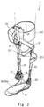
- the walking training apparatus 1 includes a walking assistance apparatus 2 mounted on an affected leg (in Fig. 1 , the right leg) of the leg parts of the user and a training apparatus 3 which performs the walking training for the user.
- the walking assistance apparatus 2 is mounted on, for example, the affected leg of the user and assists user's walking ( Fig. 2 ).
- the walking assistance apparatus 2 includes an upper thigh frame 21, a lower thigh frame 23 coupled to the upper thigh frame 21 via a knee joint part 22, a sole frame 25 coupled to the lower thigh frame 23 via an ankle joint part 24, a motor unit 26 that rotationally drives the knee joint part 22, and an adjustment mechanism 27 that adjusts a movable range of the ankle joint part 24.
- the structure of the walking assistance apparatus 2 is merely one example and the structure thereof is not limited to the one stated above.
- the walking assistance apparatus 2 may include, for example, a motor unit that rotationally drives the ankle joint part 24.
- the sole frame 25 is provided with a sole load detection unit 28 formed of a plurality of load sensors 28a that detect the load that the sole of the user receives.
- a pair of load sensors 28a are arranged on the tip side of the sole frame 25 and a pair of load sensors 28a are arranged on the heel side thereof.
- the number of load sensors 28a and the location of the load sensors 28a are not limited as long as they are arranged in such a manner that the center of the load of the sole can be accurately obtained.
- the upper thigh frame 21 is fixed to the upper thigh part of the affected leg of the user and the lower thigh frame 23 is fixed to the lower thigh part of the affected leg of the user.
- the upper thigh frame 21 is provided with, for example, an upper thigh equipment 212 to fix the upper thigh part. It is therefore possible to prevent the walking assistance apparatus 2 from being deviated in the horizontal direction or the vertical direction from the affected leg of the user.
- the upper thigh frame 21 is provided with a first frame 211 which is formed in a horizontal long shape and extends in the horizontal direction to connect a wire 34 of a first pulling unit (first pulling means) 35.
- the lower thigh frame 23 is provided with a second frame 231 which is formed in a horizontal long shape and extends in the horizontal direction to connect a wire 36 of a second pulling unit (second pulling means) 37.
- the aforementioned structure of the walking assistance apparatus 2 is merely one example and is not limited to the one described above.
- a desired walking assistance apparatus mounted on the affected leg of the user and capable of assisting the user's walking may be employed as the walking assistance apparatus 2.
- the training apparatus 3 includes a treadmill (in the drawings, the treadmill may be indicated by "TM") 31, a frame body 32, a control apparatus 33, the first pulling unit 35, and the second pulling unit 37.
- the treadmill 31 includes a rotatable ring-shaped belt 311.
- the user stands on the belt 311 and performs a walking operation in a state in which the treadmill 31 is being operated (i.e., a state in which the belt 311 is being rotated) and performs a stepping operation in a state in which the treadmill 31 is not being operated (i.e., a state in which the rotation of the belt 311 is being stopped).
- the frame body 32 includes two pairs of column frames 321 which are installed on the treadmill 31, a pair of front and rear frames 322 which are connected to the respective column frames 321 and extend in the front-back direction, and three right and left frames 323 which are connected to the front and rear frames 322 and extend in the horizontal direction.
- the aforementioned structure of the frame body 32 is not limited to the one described above.
- the frame body 32 may have any frame structure as long as the first and second pulling units 35 and 37 can be appropriately fixed to the frame body 32.
- the right and left frame 323 on the front side is provided with the first pulling unit 35 which pulls the wire 34 upward and frontward.
- the right and left frame 323 on the rear side is provided with the second pulling unit 37 which pulls the wire 36 upward and rearward.
- the first pulling unit 35 includes, for example, a mechanism which winds and rewinds the wire 34, a forward motor 351 which drives this mechanism and the like.
- the second pulling unit 37 includes, for example, a mechanism which winds and rewinds the wire 36, a backward motor 371 which drives this mechanism and the like.
- One end of the wire 34 pulled by the first pulling unit 35 is connected to the first frame 211 of the walking assistance apparatus 2 and one end of the wire 36 pulled by the second pulling unit 37 is connected to the second frame 231 of the walking assistance apparatus 2.
- the first pulling unit 35 pulls the walking assistance apparatus 2 upward and frontward via the wire 34.
- the second pulling unit 37 pulls the walking assistance apparatus 2 upward and rearward via the wire 36.
- the first pulling unit 35 and the second pulling unit 37 adjust the pulling forces of the wires 34 and 36 by adjusting relief torque of the forward motor 351 and that of the backward motor 371.
- first pulling unit 35 and second pulling unit 37 connect the wires 34 and 36 to the first frame 211 and the second frame 231 and the affected leg of the user is indirectly pulled via the walking assistance apparatus 2
- this connection is merely one example.
- a connection in which the wire 34 of the first pulling unit 35 and the wire 36 of the second pulling unit 37 are connected to the upper thigh equipment 212 and the affected leg of the user is directly pulled may be employed.
- a connection in which the wire 34 of the first pulling unit 35 and the wire 36 of the second pulling unit 37 are connected to both the first frame 211 and the second frame 231 and the upper thigh equipment 212 and the affected leg of the user is pulled directly and indirectly via the walking assistance apparatus 2 may be employed.
- the frame body 32 is provided with a display unit 324 that displays information such as training instructions, training menu, training information (walking speed, biological information etc.)
- the control apparatus 33 controls each of the pulling forces of the first pulling unit 35 and the second pulling unit 37, the operation of the treadmill 31, and the operation of the walking assistance apparatus 2.
- the control apparatus 33 includes a processor such as a Central Processing Unit (CPU) and a storage unit.
- the processor executes the program stored in the storage unit, whereby the processing of the control apparatus 33 is achieved. That is, the program stored in the storage unit of the control apparatus 33 includes a code for causing the processor to execute the processing in the control apparatus 33.
- the storage unit is configured to include, for example, a storage apparatus capable of storing the aforementioned program and various kinds of information to be used for processing in the processor.
- the storage apparatus may be at least one arbitrary storage apparatus among storage apparatuses such as a memory and a hard disc.
- Non-transitory computer readable media include any type of tangible storage media.
- Examples of non-transitory computer readable media include magnetic storage media (such as flexible disks, magnetic tapes, hard disk drives, etc.), optical magnetic storage media (e.g., magneto-optical disks), Compact Disc-Read Only Memory (CD-ROM), CD-Recordable (CD-R), CD-ReWritable (CD-R/W), and semiconductor memories (such as mask ROM, Programmable ROM (PROM), Erasable PROM (EPROM), flash ROM, Random Access Memory (RAM), etc.).
- magnetic storage media such as flexible disks, magnetic tapes, hard disk drives, etc.
- optical magnetic storage media e.g., magneto-optical disks
- CD-ROM Compact Disc-Read Only Memory
- CD-R CD-Recordable
- CD-R/W CD-ReWritable
- semiconductor memories such as mask ROM, Programmable ROM (PROM), Erasable PROM (EPROM), flash ROM, Random Access Memory
- the program may be provided to a computer using any type of transitory computer readable media.
- Examples of transitory computer readable media include electric signals, optical signals, and electromagnetic waves.
- Transitory computer readable media can provide the program to a computer via a wired communication line (e.g., electric wires, and optical fibers) or a wireless communication line.
- the main feature of this embodiment lies in the structure of controlling the pulling forces of the first pulling unit 35 and the second pulling unit 37 and known techniques can be used for the structure of controlling the operations of the walking assistance apparatus 2 and the treadmill 31. Therefore, in the following description, the structure of performing control of the pulling forces of the first pulling unit 35 and the second pulling unit 37 will be mainly described.
- Fig. 3 is a block diagram showing one example of a schematic control block configuration of the walking training apparatus 1 according to this embodiment.
- the first pulling unit 35 includes the forward motor 351 described above and the second pulling unit 37 includes the backward motor 371 described above.
- the walking assistance apparatus 2 includes the motor unit 26 and the sole load detection unit 28 described above.
- the control apparatus 33 includes a swing timing determination unit 331, a treadmill operation determination unit 332, and a control unit (control means) 333.
- the swing timing determination unit 331, the treadmill operation determination unit 332, and the control unit 333 are achieved by the processor that executes the program stored in the storage unit.
- the swing timing determination unit 331 determines, using the sole load detected by the sole load detection unit 28, a swing start timing, which is a timing when swing of the affected leg of the user on which the walking assistance apparatus 2 is mounted is started.
- a swing start timing which is a timing when swing of the affected leg of the user on which the walking assistance apparatus 2 is mounted.
- a period from the timing when the swing of the affected leg of the user is started to the timing when it ends i.e., a period in which the affected leg of the user is in a lifted leg condition, which is a state in which it is floated from the floor
- the swing timing determination unit 331 determines the swing start timing
- the swing timing determination unit 331 outputs an instruction for starting the swing to the control unit 333.
- the following method may be employed, for example, as a method of determining the swing start timing.
- a load threshold and an unload threshold are set in advance as thresholds of the sole load. Then the timing when the waveform of the sole load detected by the sole load detection unit 28 goes below the unload threshold for the first time after it exceeds the load threshold is determined to be the swing start timing.
- the treadmill operation determination unit 332 determines whether the treadmill 31 is in an operating state (i.e., a state in which the belt 311 is being rotated) or a non-operating state (i.e., a state in which the rotation of the belt 311 is being stopped).
- the following method may be employed, for example, as the method of determining the operating state of the treadmill 31.
- the control unit 333 controls the pulling forces of the first pulling unit 35 and the second pulling unit 37 in such a way as to reduce the load on the affected leg of the user. Further, the control unit 333 also controls the operation of the walking assistance apparatus 2.
- the control unit 333 Upon accepting the instruction for starting the swing from the swing timing determination unit 331, the control unit 333 brings the walking assistance apparatus 2 into the operating state (i.e., a state in which the knee joint part 22 is rotationally driven by the motor unit 26). During the swinging period, the user changes his/her knee from an extended condition to a flexed condition and then moves his/her knee back to the extended condition. Therefore, the control unit 333 brings the walking assistance apparatus 2 into the operating state and rotationally drives the knee joint part 22 by the motor unit 26 in such a way as to assist this user's motion.
- the operating state i.e., a state in which the knee joint part 22 is rotationally driven by the motor unit 26.
- control unit 333 determines whether the treadmill 31 is determined to be the operating state or the treadmill 31 is determined to be the non-operating state by the treadmill operation determination unit 332.
- the control unit 333 determines, when the treadmill 31 is in the operating state, that the user is performing the walking operation and controls the pulling forces of the first pulling unit 35 and the second pulling unit 37 in such a way as to increase the force for lifting the walking assistance apparatus 2 upward. That is, the control unit 333 controls the pulling forces of the first pulling unit 35 and the second pulling unit 37 in such a way that a resultant pulling force, which is a resultant force of the pulling forces of the first pulling unit 35 and the second pulling unit 37, is directed upward. Accordingly, when the user performs the walking operation while the treadmill 31 is in the operating state, the load of the walking assistance apparatus 2 is relieved.
- the control unit 333 determines that the user is performing the stepping operation on site and controls the pulling forces of the first pulling unit 35 and the second pulling unit 37 in such a way as to enhance the force for pulling the walking assistance apparatus 2 upward and to cause the pulling forces to be generated rearward as well. That is, the control unit 333 controls the pulling forces of the first pulling unit 35 and the second pulling unit 37 in such a way that the direction of the resultant pulling force, which is the resultant force of the pulling forces of the first pulling unit 35 and the second pulling unit 37, is changed rearward compared to the case in which the treadmill 31 is in the operating state. As a result, the resultant pulling force is directed upward and rearward.
- the control unit 333 holds time-series patterns of the relief torque of the forward motor 351 and that of the backward motor 371 during the swinging period in each of the case in which the treadmill 31 is in the operating state and the case in which it is in the non-operating state.
- the time-series patterns are patterns in which, when the treadmill 31 is in the operating state, the relief torque of the forward motor 351 and that of the backward motor 371 are controlled in such a way that the resultant pulling force is directed upward during the swinging period. Further, when the treadmill 31 is in the non-operating state, the relief torque of the forward motor 351 and that of the backward motor 371 are controlled in such a way that the resultant pulling force is directed upward and rearward during the swinging period.
- the control unit 333 upon accepting the instruction for starting the swing, the control unit 333 reads out the time-series patterns in accordance with the operating state or the non-operating state of the treadmill 31. Then the control unit 333 controls, during the following swinging period, the relief torque of the forward motor 351 and that of the backward motor 371 in accordance with the time-series patterns that have been read out, to thereby control the pulling forces of the first pulling unit 35 and the second pulling unit 37.
- Fig. 4 is a flowchart showing one example of a method of controlling the pulling forces of the first pulling unit 35 and the second pulling unit 37 in the control unit 333 of the walking training apparatus 1 according to this embodiment.
- control unit 333 determines whether it has accepted the instruction for starting the swing from the swing timing determination unit 331 (Step S11).
- Step S11 When the control unit 333 has accepted the instruction for starting the swing (YES in Step S11), the control unit 333 then brings the walking assistance apparatus 2 into the operating state and determines whether the treadmill operation determination unit 332 determines that the treadmill 31 is in the operating state or it determines that the treadmill 31 is in the non-operating state (Step S12).
- the control unit 333 3 determines that the user is performing the walking operation and controls the pulling forces of the first pulling unit 35 and the second pulling unit 37 in such a way that the resultant pulling force, which is the resultant force of the pulling forces of the first pulling unit 35 and the second pulling unit 37, is directed upward (Step S13). Specifically, the control unit 333 reads out the time-series patterns of the relief torque of the forward motor 351 and that of the backward motor 371 during the swinging period in the state in which the treadmill 31 is in the operating state and controls, during the following swinging period, the relief torque of the forward motor 351 and that of the backward motor 371 in accordance with the time-series patterns that have been read out. In this way, during the swinging period, the resultant pulling force is directed upward.
- the control unit 333 determines that the user is performing the stepping operation on site and controls the pulling forces of the first pulling unit 35 and the second pulling unit 37 in such a way that the resultant pulling force, which is the resultant force of the pulling forces of the first pulling unit 35 and the second pulling unit 37, is directed upward and rearward (Step S14).
- control unit 333 reads out the time-series patterns of the relief torque of the forward motor 351 and that of the backward motor 371 during the swinging period in the case in which the treadmill 31 is in the non-operating state and controls, during the following swinging period, the relief torque of the forward motor 351 and that of the backward motor 371 in accordance with the time-series patterns that have been read out. In this way, during the swinging period, the resultant pulling force is directed upward and rearward.
- Steps S 13 and S 14 define the control of the forward motor 351 and the backward motor 371 during the swinging period. Therefore, the end of Steps S 13 and S 14 means the end of the swinging period.
- the processes of Steps S 13 and 14 are ended, that is, when the swinging period is ended, the process goes back to Step S 11.
- the control unit 333 has accepted the next instruction for starting the swing (YES in Step S11)
- the processes in Step S 12 to S14 are performed. Therefore, Steps S11 to S14 are processes performed for each swinging period.
- the control unit 333 does not accept the instruction for starting the swing (NO in Step S11). Therefore, the control unit 333 controls the pulling forces of the first pulling unit 35 and the second pulling unit 37 in such a way that the resultant pulling force, which is the resultant force of the pulling forces of the first pulling unit 35 and the second pulling unit 37 is directed upward (Step S15).
- the relief torque of the forward motor 351 and that of the backward motor 371 in Step S15 are the same as those in the ground-contacting period.
- the relief torque of the forward motor 351 and that of the backward motor 371 are substantially the same and have a predetermined fixed value.
- Fig. 5 is a diagram showing a first example of the time-series patterns of the relief torque of the forward motor 351 and that of the backward motor 371 during the swinging period.
- the top view of Fig. 5 shows the time-series pattern of a relief torque Tfon of the forward motor 351 during the swinging period in the case in which the treadmill 31 is in the operating state (i.e., the time-series pattern of the relief torque of the forward motor 351 in Step S 13 in Fig. 4 ) and the time-series pattern of a relief torque Tfoff of the forward motor 351 during the swinging period in the case in which the treadmill 31 is in the non-operating state (i.e., the time-series pattern of the relief torque of the forward motor 351 in Step S14 in Fig. 4 ).
- FIG. 5 shows the time-series pattern of a relief torque Tbon of the backward motor 371 during the swinging period in the case in which the treadmill 31 is in the operating state (i.e., the time-series pattern of the relief torque of the backward motor 371 in Step S13 in Fig. 4 ) and the time-series pattern of a relief torque Tboff of the backward motor 371 during the swinging period in the case in which the treadmill 31 is in the non-operating state (i.e., the time-series pattern of the relief torque of the backward motor 371 in Step S14 in Fig. 4 ) (the same is applicable to Figs. 6 to 10 described below).
- the control unit 333 makes the resultant pulling force of the first pulling unit 35 and the second pulling unit 37 directed upward in such a way as to increase the force for pulling the walking assistance apparatus 2 upward.
- the control unit 333 when the treadmill 31 is in the operating state at the time when the control unit 333 has accepted the instruction for starting the swing, the control unit 333 gradually increases the relief torque Tfon of the forward motor 351 and the relief torque Tbon of the backward motor 371 from the fixed value in the ground-contacting period and then returns it to the fixed value in the ground-contacting period.
- the relief torque Tfon and the relief torque Tbon are made substantially the same.
- the control unit 333 makes the resultant pulling force of the first pulling unit 35 and the second pulling unit 37 directed upward and rearward in such a way as to increase the force for pulling the walking assistance apparatus 2 upward and to cause the pulling forces to be generated rearward as well.
- the control unit 333 uniformly makes, for the whole swinging period, the relief torque Tboff of the backward motor 371 larger than the relief torque Tbon of the backward motor 371 in the case in which the treadmill 31 is in the operating state.
- the relief torque Tfoff of the forward motor 351 is made substantially the same as the relief torque Tfon of the forward motor 351 in the case in which the treadmill 31 is in the operating state.
- the resultant pulling force of the first pulling unit 35 and the second pulling unit 37 is directed upward and rearward. Therefore, when the user performs the stepping operation while the treadmill 31 is in the non-operating state, for the whole swinging period, the affected leg of the user can be pulled backward, whereby it is possible to suppress the user from moving forward in accordance with the stepping operation.
- Fig. 6 is a diagram showing a second example of the time-series patterns of the relief torque of the forward motor 351 and that of the backward motor 371 during the swinging period.
- the relief torque Tfon of the forward motor 351 and the relief torque Tbon of the backward motor 371 during the swinging period in the case in which the treadmill 31 is in the operating state at the time when the control unit 333 has accepted the instruction for starting the swing are the same as those in the first example.
- the control unit 333 uniformly makes, for the whole swinging period, the relief torque Tfoff of the forward motor 351 smaller than the relief torque Tfon of the forward motor 351 in the case in which the treadmill 31 is in the operating state.
- the relief torque Tboff of the backward motor 371 is made substantially the same as the relief torque Tbon of the backward motor 371 in the case in which the treadmill 31 is in the operating state.
- the resultant pulling force of the first pulling unit 35 and the second pulling unit 37 is directed relatively upward and rearward. Therefore, when the user performs the stepping operation while the treadmill 31 is in the non-operating state, for the whole swinging period, the affected leg of the user can be pulled backward, whereby it is possible to suppress the user from moving forward in accordance with the stepping operation.
- Fig. 7 is a diagram showing a third example of the time-series patterns of the relief torque of the forward motor 351 and that of the backward motor 371 during the swinging period.
- the relief torque Tfon of the forward motor 351 and the relief torque Tbon of the backward motor 371 during the swinging period in the case in which the treadmill 31 is in the operating state at the time when the control unit 333 has accepted the instruction for starting the swing are the same as those in the first example.
- the control unit 333 makes the relief torque Tboff of the backward motor 371 larger than the relief torque Tbon of the backward motor 371 in the case in which the treadmill 31 is in the operating state, in the swinging period except for the timing when the swing is started and the swing is ended.
- the relief torque Tboff is set to a fixed value in the ground-contacting period when the swing is started and the swing is ended, similar to the relief torque Tbon.
- the relief torque Tfoff of the forward motor 351 is made substantially the same as the relief torque Tfon of the forward motor 351 when the treadmill 31 is in the operating state.
- the resultant pulling force of the first pulling unit 35 and the second pulling unit 37 is directed upward and rearward. Therefore, when the user performs the stepping operation while the treadmill 31 is in the non-operating state, in the period in which the affected leg of the user is actually in the lifted leg condition, the affected leg of the user can be pulled backward, whereby it is possible to suppress the user from moving forward in accordance with the stepping operation.
- the relief torque Tboff of the backward motor 371 is set to a fixed value in the ground-contacting period when the swing is started and the swing is ended. Accordingly, the relief torque of the backward motor 371 can be smoothly changed when the ground-contacting period is changed to the swinging period and the swinging period is changed to the ground-contacting period.
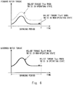
- Fig. 8 is a diagram showing a fourth example of the time-series patterns of the relief torque of the forward motor 351 and that of the backward motor 371 during the swinging period.
- the relief torque Tfon of the forward motor 351 and the relief torque Tbon of the backward motor 371 during the swinging period in the case in which the treadmill 31 is in the operating state at the time when the control unit 333 has accepted the instruction for starting the swing are the same as those in the first example.
- the control unit 333 makes the relief torque Tfoff of the forward motor 351 smaller than the relief torque Tfon of the forward motor 351 in the case in which the treadmill 31 is in the operating state, in the swinging period except for the timing when the swing is started and the swing is ended.
- the relief torque Tfoff is set to a fixed value in the ground-contacting period when the swing is started and the swing is ended, similar to the relief torque Tfon.
- the relief torque Tboff of the backward motor 371 is made substantially the same as the relief torque Tbon of the backward motor 371 in the case in which the treadmill 31 is in the operating state.
- the resultant pulling force of the first pulling unit 35 and the second pulling unit 37 is directed relatively upward and rearward. Therefore, when the user performs the stepping operation while the treadmill 31 is in the non-operating state, in the period in which the affected leg of the user is actually in the lifted leg condition, the affected leg of the user can be pulled backward, whereby it is possible to suppress the user from moving forward in accordance with the stepping operation.
- the relief torque Tfoff of the forward motor 351 is set to a fixed value in the ground-contacting period when the swing is started and the swing is ended. Accordingly, the relief torque of the forward motor 351 can be smoothly changed when the ground-contacting period is changed to the swinging period and the swinging period is changed to the ground-contacting period.
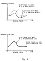
- Fig. 9 is a diagram showing a fifth example of the time-series patterns of the relief torque of the forward motor 351 and that of the backward motor 371 during the swinging period.
- the relief torque Tfon of the forward motor 351 and the relief torque Tbon of the backward motor 371 during the swinging period in the case in which the treadmill 31 is in the operating state at the time when the control unit 333 has accepted the instruction for starting the swing are the same as those in the first example.
- the control unit 333 makes the relief torque Tboff of the backward motor 371 larger than the relief torque Tbon of the backward motor 371 in the case in which the treadmill 31 is in the operating state, in a period after a predetermined time position t1 during the swinging period.
- the relief torque Tboff is set to a fixed value in the ground-contacting period, similar to the relief torque Tbon.
- the relief torque Tfoff of the forward motor 351 is made substantially the same as the relief torque Tfon of the forward motor 351 in the case in which the treadmill 31 is in the operating state.
- the resultant pulling force of the first pulling unit 35 and the second pulling unit 37 is directed upward and rearward. Therefore, when the user performs the stepping operation while the treadmill 31 is in the non-operating state, the affected leg of the user can be pulled backward at least just before the affected leg of the user contacts the floor, whereby it is possible to suppress the user from moving forward in accordance with the stepping operation.
- the predetermined time position t1 is set to substantially the center of the swinging period and the relief torque Tboff is made larger than the relief torque Tbon in the latter part of the swinging period in Fig. 9 , this configuration is merely an example. In the fifth example, it is sufficient that the relief torque Tboff be larger than the relief torque Tbon just before the swing is ended. Therefore, the predetermined time position t1 may be before or after substantially the center of the swinging period.
- the relief torque Tboff is set to a fixed value in the ground-contacting period when the swing is ended, similar to the relief torque Tbon, in Fig. 9 , this configuration is merely an example.
- the relief torque Tboff may be made larger than the relief torque Tbon also when the swing is ended.
- Fig. 10 is a diagram showing a sixth example of the time-series patterns of the relief torque of the forward motor 351 and that of the backward motor 371 during the swinging period.
- the relief torque Tfon of the forward motor 351 and the relief torque Tbon of the backward motor 371 during the swinging period in the case in which the treadmill 31 is in the operating state at the time when the control unit 333 has accepted the instruction for starting the swing are similar to those in the first example.
- the control unit 333 makes the relief torque Tfoff of the forward motor 351 smaller than the relief torque Tfon of the forward motor 351 in the case in which the treadmill 31 is in the operating state, in the period after the predetermined time position t1 during the swinging period.
- the relief torque Tfoff is set to a fixed value in the ground-contacting period when the swing is started and the swing is ended, similar to the relief torque Tfon.
- the relief torque Tboff of the backward motor 371 is made substantially the same as the relief torque Tbon of the backward motor 371 in the case in which the treadmill 31 is in the operating state.
- the resultant pulling force of the first pulling unit 35 and the second pulling unit 37 is directed relatively upward and rearward. Therefore, when the user performs the stepping operation while the treadmill 31 is in the non-operating state, the affected leg of the user can be pulled backward at least just before the affected leg of the user contacts the floor, whereby it is possible to suppress the user from moving forward in accordance with the stepping operation.
- the predetermined time position t1 is set to substantially the center of the swinging period and the relief torque Tfoff is made smaller than the relief torque Tfon in the latter part of the swinging period in Fig. 10 , this configuration is merely an example. In the sixth example, it is sufficient that the relief torque Tfoff be smaller than the relief torque Tfon immediately before the swing is ended. Therefore, the predetermined time position t1 may be before or after the substantially the center of the swinging period.
- the relief torque Tfoff is set to a fixed value in the ground-contacting period when the swing is ended, similar to the relief torque Tfon, in Fig. 10 , this configuration is merely an example.
- the relief torque Tfoff may be made smaller than the relief torque Tfon also when the swing is ended.
- the control unit 333 controls, when the treadmill 31 is in the non-operating state, the pulling forces of the first pulling unit 35 and the second pulling unit 37 in such a way that the resultant pulling force, which is the resultant force of the pulling forces of the first pulling unit 35 and the second pulling unit 37, is changed backward compared to the case in which the treadmill 31 is in the operating state. Therefore, when the user performs the stepping operation while the treadmill 31 is in the non-operating state, it becomes easier for the user to bring back the affected leg rearward. Accordingly, it is possible to suppress the user from moving forward in accordance with the stepping operation, whereby it is possible to suppress the possibility that a burden is imposed on the user when the user performs the stepping operation.
- control unit 333 controls, when the treadmill 31 is in the non-operating state in the state in which the walking assistance apparatus 2 is in the operating state, the pulling forces of the first pulling unit 35 and the second pulling unit 37 in such a way that the resultant pulling force, which is the resultant force of the pulling forces of the first pulling unit 35 and the second pulling unit 37, is changed rearward compared to the case in which the treadmill 31 is in the operating state. Accordingly, it is possible to suppress the possibility that a burden is imposed on the user while the user is performing the stepping operation, which is close to the walking operation for operating the walking assistance apparatus 2.
- the walking assistance apparatus is in the operating state at the time when the instruction for starting the swing has been accepted. Therefore, the stepping operation is performed while the walking assistance apparatus is in the operating state.
- the stepping operation may be performed while the walking assistance apparatus is in the non-operating state. In this case, the walking assistance apparatus is brought into the operating state only during the walking operation. Therefore, the timing when the walking assistance apparatus is brought into the operating state may be a timing when it is determined that the treadmill is in the operating state after the instruction for starting the swing has been accepted.
- the pulling forces of the first and second pulling units are controlled by adjusting the relief torque of the motors in the aforementioned embodiment, this is merely an example.
- the first and second pulling units may include spring members connected to the respective wires and the pulling forces of the first and second pulling units may be controlled by adjusting the elastic forces of the spring members.
- a walking training apparatus includes: a treadmill; a walking assistance apparatus configured to be mounted on a leg part of a user and assist the user's walking; a first pulling means for pulling at least one of the walking assistance apparatus and the leg part of the user upward and frontward; a second pulling means for pulling at least one of the walking assistance apparatus and the leg part of the user upward and rearward; and control means for controlling, while the treadmill is not being operated, pulling forces of the first pulling means and the second pulling means in such a way that the direction of a resultant pulling force, which is a resultant force of the pulling force of the first pulling means and the pulling force of the second pulling means, is changed rearward compared to a case in which the treadmill is being operated.
Landscapes
- Health & Medical Sciences (AREA)
- General Health & Medical Sciences (AREA)
- Physical Education & Sports Medicine (AREA)
- Life Sciences & Earth Sciences (AREA)
- Animal Behavior & Ethology (AREA)
- Public Health (AREA)
- Veterinary Medicine (AREA)
- Epidemiology (AREA)
- Pain & Pain Management (AREA)
- Rehabilitation Therapy (AREA)
- Orthopedic Medicine & Surgery (AREA)
- Biophysics (AREA)
- Engineering & Computer Science (AREA)
- Cardiology (AREA)
- Vascular Medicine (AREA)
- Physics & Mathematics (AREA)
- Oral & Maxillofacial Surgery (AREA)
- Pathology (AREA)
- Dentistry (AREA)
- Biomedical Technology (AREA)
- Heart & Thoracic Surgery (AREA)
- Medical Informatics (AREA)
- Molecular Biology (AREA)
- Surgery (AREA)
- Computer Vision & Pattern Recognition (AREA)
- Psychiatry (AREA)
- Social Psychology (AREA)
- Human Computer Interaction (AREA)
- General Physics & Mathematics (AREA)
- Multimedia (AREA)
- Theoretical Computer Science (AREA)
- Rehabilitation Tools (AREA)
Abstract
Description
- The present invention relates to a walking training apparatus used by a user to perform walking training and a method of controlling the same.
- A walking training apparatus by which a user performs walking training on a treadmill with a walking assistance apparatus that assists user's walking attached to his/her leg part has been known (see, for example, Japanese Unexamined Patent Application Publication No.
2015-223294 - The walking training apparatus disclosed in Japanese Unexamined Patent Application Publication No.
2015-223294 - Incidentally, in recent walking training, the user may perform a stepping operation on site while the treadmill is in a non-operating state, and then after learning the walking rhythm through the stepping operation, the user may operate the treadmill to perform a walking operation.
- It is assumed that the user performs the walking operation in a state in which the treadmill is in an operating state in the walking training apparatus disclosed in Japanese Unexamined Patent Application Publication No.
2015-223294 - Therefore, when the user performs the stepping operation while the treadmill is in the non-operating state in the walking training apparatus disclosed in Japanese Unexamined Patent Application Publication No.
2015-223294 - The present invention has been made in view of the aforementioned circumstances and provides a walking training apparatus capable of suppressing the possibility that a burden is imposed on the user while the user is performing the stepping operation and a method of controlling the same.
- A walking training apparatus according to one aspect of the present invention includes:
- a treadmill;
- a walking assistance apparatus configured to be mounted on a leg part of a user and assist the user's walking;
- a first pulling means for pulling at least one of the walking assistance apparatus and the leg part of the user on which the walking assistance apparatus is mounted upward and frontward;
- a second pulling means for pulling at least one of the walking assistance apparatus and the leg part of the user on which the walking assistance apparatus is mounted upward and rearward; and
- a control means for controlling pulling forces of the first pulling means and the second pulling means in such a way as to reduce a load applied to the leg part of the user on which the walking assistance apparatus is mounted, in which
- the control means controls, while the treadmill is not being operated, pulling forces of the first pulling means and the second pulling means in such a way that the direction of a resultant pulling force, which is a resultant force of the pulling force of the first pulling means and the pulling force of the second pulling means, is changed rearward compared to a case in which the treadmill is being operated.
- A method of controlling a walking training apparatus according to one aspect of the present invention is a method of controlling a walking training apparatus, the walking training apparatus including:
- a treadmill;
- a walking assistance apparatus configured to be mounted on a leg part of the user and assist the user's walking;
- a first pulling means for pulling at least one of the walking assistance apparatus and the leg part of the user on which the walking assistance apparatus is mounted upward and frontward; and
- a second pulling means for pulling at least one of the walking assistance apparatus and the leg part of the user on which the walking assistance apparatus is mounted upward and rearward, the method including:
- controlling, while the treadmill is not being operated, pulling forces of the first pulling means and the second pulling means in such a way that the direction of a resultant pulling force, which is a resultant force of the pulling force of the first pulling means and the pulling force of the second pulling means, is changed rearward compared to a case in which the treadmill is being operated.
- According to the aspects of the present invention, it is possible to provide a walking training apparatus capable of suppressing the possibility that a burden is imposed on the user while the user is performing the stepping operation and a method of controlling the same.
- The above and other objects, features and advantages of the present invention will become more fully understood from the detailed description given hereinbelow and the accompanying drawings which are given by way of illustration only, and thus are not to be considered as limiting the present invention.
-
-
Fig. 1 is a perspective view showing one example of a schematic external configuration of a walking training apparatus according to an embodiment of the present invention; -
Fig. 2 is a perspective view showing one example of a schematic external configuration of a walking assistance apparatus according to the embodiment of the present invention; -
Fig. 3 is a block diagram showing one example of a schematic control block configuration of the walking training apparatus according to the embodiment of the present invention; -
Fig. 4 is a flowchart showing one example of a schematic flow of a method of controlling the walking training apparatus according to the embodiment of the present invention; -
Fig. 5 is a diagram showing a first example of time-series patterns of relief torque of a forward motor and that of a backward motor in a swinging period in the walking training apparatus according to the embodiment of the present invention; -
Fig. 6 is a diagram showing a second example of the time-series patterns of the relief torque of the forward motor and that of the backward motor in the swinging period in the walking training apparatus according to the embodiment of the present invention; -
Fig. 7 is a diagram showing a third example of the time-series patterns of the relief torque of the forward motor and that of the backward motor in the swinging period in the walking training apparatus according to the embodiment of the present invention; -
Fig. 8 is a diagram showing a fourth example of the time-series patterns of the relief torque of the forward motor and that of the backward motor in the swinging period in the walking training apparatus according to the embodiment of the present invention; -
Fig. 9 is a diagram showing a fifth example of the time-series patterns of the relief torque of the forward motor and that of the backward motor in the swinging period in the walking training apparatus according to the embodiment of the present invention; and -
Fig. 10 is a diagram showing a sixth example of the time-series patterns of the relief torque of the forward motor and that of the backward motor in the swinging period in the walking training apparatus according to the embodiment of the present invention. - A specific embodiment of the present invention is explained hereinafter in detail with reference to the drawings. In the drawings, the same or corresponding elements are denoted by the same reference signs, and repetitive descriptions will be avoided as necessary for clarity of explanation.
-
Fig. 1 is a perspective view showing one example of a schematic external configuration of awalking training apparatus 1 according to an embodiment of the present invention. Thewalking training apparatus 1 is an apparatus that is used to perform, for example, walking training for a user such as a patent suffering from hemiplegia. Thewalking training apparatus 1 includes awalking assistance apparatus 2 mounted on an affected leg (inFig. 1 , the right leg) of the leg parts of the user and atraining apparatus 3 which performs the walking training for the user. - The
walking assistance apparatus 2 is mounted on, for example, the affected leg of the user and assists user's walking (Fig. 2 ). Thewalking assistance apparatus 2 includes anupper thigh frame 21, alower thigh frame 23 coupled to theupper thigh frame 21 via a kneejoint part 22, asole frame 25 coupled to thelower thigh frame 23 via an anklejoint part 24, amotor unit 26 that rotationally drives the kneejoint part 22, and anadjustment mechanism 27 that adjusts a movable range of the anklejoint part 24. The structure of thewalking assistance apparatus 2 is merely one example and the structure thereof is not limited to the one stated above. Thewalking assistance apparatus 2 may include, for example, a motor unit that rotationally drives the anklejoint part 24. - The
sole frame 25 is provided with a soleload detection unit 28 formed of a plurality ofload sensors 28a that detect the load that the sole of the user receives. InFig. 2 , a pair ofload sensors 28a are arranged on the tip side of thesole frame 25 and a pair ofload sensors 28a are arranged on the heel side thereof. The number ofload sensors 28a and the location of theload sensors 28a are not limited as long as they are arranged in such a manner that the center of the load of the sole can be accurately obtained. - The
upper thigh frame 21 is fixed to the upper thigh part of the affected leg of the user and thelower thigh frame 23 is fixed to the lower thigh part of the affected leg of the user. Theupper thigh frame 21 is provided with, for example, anupper thigh equipment 212 to fix the upper thigh part. It is therefore possible to prevent thewalking assistance apparatus 2 from being deviated in the horizontal direction or the vertical direction from the affected leg of the user. - The
upper thigh frame 21 is provided with afirst frame 211 which is formed in a horizontal long shape and extends in the horizontal direction to connect awire 34 of a first pulling unit (first pulling means) 35. Thelower thigh frame 23 is provided with asecond frame 231 which is formed in a horizontal long shape and extends in the horizontal direction to connect awire 36 of a second pulling unit (second pulling means) 37. - The aforementioned structure of the
walking assistance apparatus 2 is merely one example and is not limited to the one described above. A desired walking assistance apparatus mounted on the affected leg of the user and capable of assisting the user's walking may be employed as thewalking assistance apparatus 2. - The
training apparatus 3 includes a treadmill (in the drawings, the treadmill may be indicated by "TM") 31, aframe body 32, acontrol apparatus 33, thefirst pulling unit 35, and thesecond pulling unit 37. Thetreadmill 31 includes a rotatable ring-shaped belt 311. When performing walking training, the user stands on thebelt 311 and performs a walking operation in a state in which thetreadmill 31 is being operated (i.e., a state in which thebelt 311 is being rotated) and performs a stepping operation in a state in which thetreadmill 31 is not being operated (i.e., a state in which the rotation of thebelt 311 is being stopped). - The
frame body 32 includes two pairs ofcolumn frames 321 which are installed on thetreadmill 31, a pair of front andrear frames 322 which are connected to therespective column frames 321 and extend in the front-back direction, and three right andleft frames 323 which are connected to the front andrear frames 322 and extend in the horizontal direction. The aforementioned structure of theframe body 32 is not limited to the one described above. Theframe body 32 may have any frame structure as long as the first andsecond pulling units frame body 32. - The right and
left frame 323 on the front side is provided with thefirst pulling unit 35 which pulls thewire 34 upward and frontward. The right andleft frame 323 on the rear side is provided with thesecond pulling unit 37 which pulls thewire 36 upward and rearward. - The first pulling
unit 35 includes, for example, a mechanism which winds and rewinds thewire 34, aforward motor 351 which drives this mechanism and the like. The second pullingunit 37 includes, for example, a mechanism which winds and rewinds thewire 36, abackward motor 371 which drives this mechanism and the like. One end of thewire 34 pulled by the first pullingunit 35 is connected to thefirst frame 211 of the walkingassistance apparatus 2 and one end of thewire 36 pulled by the second pullingunit 37 is connected to thesecond frame 231 of the walkingassistance apparatus 2. The first pullingunit 35 pulls the walkingassistance apparatus 2 upward and frontward via thewire 34. The second pullingunit 37 pulls the walkingassistance apparatus 2 upward and rearward via thewire 36. The first pullingunit 35 and the second pullingunit 37 adjust the pulling forces of thewires forward motor 351 and that of thebackward motor 371. - While the aforementioned first pulling
unit 35 and second pullingunit 37 connect thewires first frame 211 and thesecond frame 231 and the affected leg of the user is indirectly pulled via thewalking assistance apparatus 2, this connection is merely one example. A connection in which thewire 34 of the first pullingunit 35 and thewire 36 of the second pullingunit 37 are connected to theupper thigh equipment 212 and the affected leg of the user is directly pulled may be employed. Alternatively, a connection in which thewire 34 of the first pullingunit 35 and thewire 36 of the second pullingunit 37 are connected to both thefirst frame 211 and thesecond frame 231 and theupper thigh equipment 212 and the affected leg of the user is pulled directly and indirectly via thewalking assistance apparatus 2 may be employed. - The
frame body 32 is provided with adisplay unit 324 that displays information such as training instructions, training menu, training information (walking speed, biological information etc.) - The
control apparatus 33 controls each of the pulling forces of the first pullingunit 35 and the second pullingunit 37, the operation of thetreadmill 31, and the operation of the walkingassistance apparatus 2. Thecontrol apparatus 33 includes a processor such as a Central Processing Unit (CPU) and a storage unit. The processor executes the program stored in the storage unit, whereby the processing of thecontrol apparatus 33 is achieved. That is, the program stored in the storage unit of thecontrol apparatus 33 includes a code for causing the processor to execute the processing in thecontrol apparatus 33. The storage unit is configured to include, for example, a storage apparatus capable of storing the aforementioned program and various kinds of information to be used for processing in the processor. The storage apparatus may be at least one arbitrary storage apparatus among storage apparatuses such as a memory and a hard disc. - Further, the aforementioned program can be stored and provided to a computer using any type of non-transitory computer readable media. Non-transitory computer readable media include any type of tangible storage media. Examples of non-transitory computer readable media include magnetic storage media (such as flexible disks, magnetic tapes, hard disk drives, etc.), optical magnetic storage media (e.g., magneto-optical disks), Compact Disc-Read Only Memory (CD-ROM), CD-Recordable (CD-R), CD-ReWritable (CD-R/W), and semiconductor memories (such as mask ROM, Programmable ROM (PROM), Erasable PROM (EPROM), flash ROM, Random Access Memory (RAM), etc.). The program may be provided to a computer using any type of transitory computer readable media. Examples of transitory computer readable media include electric signals, optical signals, and electromagnetic waves. Transitory computer readable media can provide the program to a computer via a wired communication line (e.g., electric wires, and optical fibers) or a wireless communication line.
- The main feature of this embodiment lies in the structure of controlling the pulling forces of the first pulling
unit 35 and the second pullingunit 37 and known techniques can be used for the structure of controlling the operations of the walkingassistance apparatus 2 and thetreadmill 31. Therefore, in the following description, the structure of performing control of the pulling forces of the first pullingunit 35 and the second pullingunit 37 will be mainly described. -
Fig. 3 is a block diagram showing one example of a schematic control block configuration of the walkingtraining apparatus 1 according to this embodiment. The first pullingunit 35 includes theforward motor 351 described above and the second pullingunit 37 includes thebackward motor 371 described above. The walkingassistance apparatus 2 includes themotor unit 26 and the soleload detection unit 28 described above. Thecontrol apparatus 33 includes a swingtiming determination unit 331, a treadmilloperation determination unit 332, and a control unit (control means) 333. The swingtiming determination unit 331, the treadmilloperation determination unit 332, and thecontrol unit 333 are achieved by the processor that executes the program stored in the storage unit. - The swing
timing determination unit 331 determines, using the sole load detected by the soleload detection unit 28, a swing start timing, which is a timing when swing of the affected leg of the user on which thewalking assistance apparatus 2 is mounted is started. In the following description, a period from the timing when the swing of the affected leg of the user is started to the timing when it ends (i.e., a period in which the affected leg of the user is in a lifted leg condition, which is a state in which it is floated from the floor) is called a swinging period. When the swingtiming determination unit 331 determines the swing start timing, the swingtiming determination unit 331 outputs an instruction for starting the swing to thecontrol unit 333. - The following method may be employed, for example, as a method of determining the swing start timing.
- A load threshold and an unload threshold (load threshold > unload threshold) are set in advance as thresholds of the sole load. Then the timing when the waveform of the sole load detected by the sole
load detection unit 28 goes below the unload threshold for the first time after it exceeds the load threshold is determined to be the swing start timing. - The treadmill
operation determination unit 332 determines whether thetreadmill 31 is in an operating state (i.e., a state in which thebelt 311 is being rotated) or a non-operating state (i.e., a state in which the rotation of thebelt 311 is being stopped). - The following method may be employed, for example, as the method of determining the operating state of the
treadmill 31. - (A) An operation start instruction button that instructs the start of the operation of the
treadmill 31 and an operation end instruction button that instructs the end of the operation of thetreadmill 31 are provided. Then the period from the timing when the operation start instruction button is pressed to the timing when the operation end instruction button is pressed is determined to be the period in which thetreadmill 31 is in the operating state. - (B) An angle sensor that detects the angle of the rotation axis of the
treadmill 31 is provided. When the angle of the rotation axis of thetreadmill 31 detected by the angle sensor is changed to a predetermined threshold or more, it is determined that thetreadmill 31 is in the operating state. - (C) One or more markers are arranged on the
belt 311 of thetreadmill 31 along the rotation direction and an imaging apparatus that captures images of thebelt 311 in such a way that the marker(s) are included in the captured images is provided. Then the rotational speed of thebelt 311 is determined based on the timing when the marker(s) appears on the images captured by the imaging apparatus. When the rotational speed of thebelt 311 is equal to or larger than a predetermined threshold, it is determined that thetreadmill 31 is in the operating state. - (D) An ammeter that measures the current flowing through a power supply cable of the
treadmill 31 is provided. When the current value measured by the ammeter is not zero, it is determined that thetreadmill 31 is in the operating state. - The
control unit 333 controls the pulling forces of the first pullingunit 35 and the second pullingunit 37 in such a way as to reduce the load on the affected leg of the user. Further, thecontrol unit 333 also controls the operation of the walkingassistance apparatus 2. - Upon accepting the instruction for starting the swing from the swing
timing determination unit 331, thecontrol unit 333 brings the walkingassistance apparatus 2 into the operating state (i.e., a state in which the kneejoint part 22 is rotationally driven by the motor unit 26). During the swinging period, the user changes his/her knee from an extended condition to a flexed condition and then moves his/her knee back to the extended condition. Therefore, thecontrol unit 333 brings the walkingassistance apparatus 2 into the operating state and rotationally drives the kneejoint part 22 by themotor unit 26 in such a way as to assist this user's motion. - Further, upon accepting the instruction for starting the swing from the swing
timing determination unit 331, thecontrol unit 333 determines whether thetreadmill 31 is determined to be the operating state or thetreadmill 31 is determined to be the non-operating state by the treadmilloperation determination unit 332. - The
control unit 333 determines, when thetreadmill 31 is in the operating state, that the user is performing the walking operation and controls the pulling forces of the first pullingunit 35 and the second pullingunit 37 in such a way as to increase the force for lifting the walkingassistance apparatus 2 upward. That is, thecontrol unit 333 controls the pulling forces of the first pullingunit 35 and the second pullingunit 37 in such a way that a resultant pulling force, which is a resultant force of the pulling forces of the first pullingunit 35 and the second pullingunit 37, is directed upward. Accordingly, when the user performs the walking operation while thetreadmill 31 is in the operating state, the load of the walkingassistance apparatus 2 is relieved. - On the other hand, when the
treadmill 31 is in the non-operating state, thecontrol unit 333 determines that the user is performing the stepping operation on site and controls the pulling forces of the first pullingunit 35 and the second pullingunit 37 in such a way as to enhance the force for pulling the walkingassistance apparatus 2 upward and to cause the pulling forces to be generated rearward as well. That is, thecontrol unit 333 controls the pulling forces of the first pullingunit 35 and the second pullingunit 37 in such a way that the direction of the resultant pulling force, which is the resultant force of the pulling forces of the first pullingunit 35 and the second pullingunit 37, is changed rearward compared to the case in which thetreadmill 31 is in the operating state. As a result, the resultant pulling force is directed upward and rearward. Accordingly, when the user performs the stepping operation while thetreadmill 31 is in the non-operating state, it becomes easier for the user to bring back the affected leg rearward. Accordingly, it is possible to suppress the user from moving forward in accordance with the stepping operation, whereby it is possible to suppress the possibility that a burden is imposed on the user when the user performs the stepping operation. - The
control unit 333 holds time-series patterns of the relief torque of theforward motor 351 and that of thebackward motor 371 during the swinging period in each of the case in which thetreadmill 31 is in the operating state and the case in which it is in the non-operating state. The time-series patterns are patterns in which, when thetreadmill 31 is in the operating state, the relief torque of theforward motor 351 and that of thebackward motor 371 are controlled in such a way that the resultant pulling force is directed upward during the swinging period. Further, when thetreadmill 31 is in the non-operating state, the relief torque of theforward motor 351 and that of thebackward motor 371 are controlled in such a way that the resultant pulling force is directed upward and rearward during the swinging period. - Therefore, upon accepting the instruction for starting the swing, the
control unit 333 reads out the time-series patterns in accordance with the operating state or the non-operating state of thetreadmill 31. Then thecontrol unit 333 controls, during the following swinging period, the relief torque of theforward motor 351 and that of thebackward motor 371 in accordance with the time-series patterns that have been read out, to thereby control the pulling forces of the first pullingunit 35 and the second pullingunit 37. -
Fig. 4 is a flowchart showing one example of a method of controlling the pulling forces of the first pullingunit 35 and the second pullingunit 37 in thecontrol unit 333 of the walkingtraining apparatus 1 according to this embodiment. - First, the
control unit 333 determines whether it has accepted the instruction for starting the swing from the swing timing determination unit 331 (Step S11). - When the
control unit 333 has accepted the instruction for starting the swing (YES in Step S11), thecontrol unit 333 then brings the walkingassistance apparatus 2 into the operating state and determines whether the treadmilloperation determination unit 332 determines that thetreadmill 31 is in the operating state or it determines that thetreadmill 31 is in the non-operating state (Step S12). - When the
treadmill 31 is in the operating state (YES in Step S12), thecontrol unit 333 3 determines that the user is performing the walking operation and controls the pulling forces of the first pullingunit 35 and the second pullingunit 37 in such a way that the resultant pulling force, which is the resultant force of the pulling forces of the first pullingunit 35 and the second pullingunit 37, is directed upward (Step S13). Specifically, thecontrol unit 333 reads out the time-series patterns of the relief torque of theforward motor 351 and that of thebackward motor 371 during the swinging period in the state in which thetreadmill 31 is in the operating state and controls, during the following swinging period, the relief torque of theforward motor 351 and that of thebackward motor 371 in accordance with the time-series patterns that have been read out. In this way, during the swinging period, the resultant pulling force is directed upward. - On the other hand, when the
treadmill 31 is in the non-operating state (NO in Step S12), thecontrol unit 333 determines that the user is performing the stepping operation on site and controls the pulling forces of the first pullingunit 35 and the second pullingunit 37 in such a way that the resultant pulling force, which is the resultant force of the pulling forces of the first pullingunit 35 and the second pullingunit 37, is directed upward and rearward (Step S14). Specifically, thecontrol unit 333 reads out the time-series patterns of the relief torque of theforward motor 351 and that of thebackward motor 371 during the swinging period in the case in which thetreadmill 31 is in the non-operating state and controls, during the following swinging period, the relief torque of theforward motor 351 and that of thebackward motor 371 in accordance with the time-series patterns that have been read out. In this way, during the swinging period, the resultant pulling force is directed upward and rearward. - As described above,
Steps S 13 andS 14 define the control of theforward motor 351 and thebackward motor 371 during the swinging period. Therefore, the end of Steps S 13 andS 14 means the end of the swinging period. When the processes of Steps S 13 and 14 are ended, that is, when the swinging period is ended, the process goes back toStep S 11. When thecontrol unit 333 has accepted the next instruction for starting the swing (YES in Step S11), the processes inStep S 12 to S14 are performed. Therefore, Steps S11 to S14 are processes performed for each swinging period. - In a period other than the swinging period (i.e., a period in which the affected leg of the user is in a standing-leg state, which is a state in which it contacts the floor and this period will be hereinafter called a ground-contacting period), the
control unit 333 does not accept the instruction for starting the swing (NO in Step S11). Therefore, thecontrol unit 333 controls the pulling forces of the first pullingunit 35 and the second pullingunit 37 in such a way that the resultant pulling force, which is the resultant force of the pulling forces of the first pullingunit 35 and the second pullingunit 37 is directed upward (Step S15). The relief torque of theforward motor 351 and that of thebackward motor 371 in Step S15 are the same as those in the ground-contacting period. During the ground-contacting period, the relief torque of theforward motor 351 and that of thebackward motor 371 are substantially the same and have a predetermined fixed value. - In the following description, specific examples of the time-series patterns of the relief torque of the
forward motor 351 and that of thebackward motor 371 during the swinging period will be described. -
Fig. 5 is a diagram showing a first example of the time-series patterns of the relief torque of theforward motor 351 and that of thebackward motor 371 during the swinging period. - The top view of
Fig. 5 shows the time-series pattern of a relief torque Tfon of theforward motor 351 during the swinging period in the case in which thetreadmill 31 is in the operating state (i.e., the time-series pattern of the relief torque of theforward motor 351 inStep S 13 inFig. 4 ) and the time-series pattern of a relief torque Tfoff of theforward motor 351 during the swinging period in the case in which thetreadmill 31 is in the non-operating state (i.e., the time-series pattern of the relief torque of theforward motor 351 in Step S14 inFig. 4 ). On the other hand, the bottom view ofFig. 5 shows the time-series pattern of a relief torque Tbon of thebackward motor 371 during the swinging period in the case in which thetreadmill 31 is in the operating state (i.e., the time-series pattern of the relief torque of thebackward motor 371 in Step S13 inFig. 4 ) and the time-series pattern of a relief torque Tboff of thebackward motor 371 during the swinging period in the case in which thetreadmill 31 is in the non-operating state (i.e., the time-series pattern of the relief torque of thebackward motor 371 in Step S14 inFig. 4 ) (the same is applicable toFigs. 6 to 10 described below). - When the
treadmill 31 is in the operating state at the time when thecontrol unit 333 has accepted the instruction for starting the swing, as described above, thecontrol unit 333 makes the resultant pulling force of the first pullingunit 35 and the second pullingunit 37 directed upward in such a way as to increase the force for pulling the walkingassistance apparatus 2 upward. - In the first example, when the
treadmill 31 is in the operating state at the time when thecontrol unit 333 has accepted the instruction for starting the swing, thecontrol unit 333 gradually increases the relief torque Tfon of theforward motor 351 and the relief torque Tbon of thebackward motor 371 from the fixed value in the ground-contacting period and then returns it to the fixed value in the ground-contacting period. In this case, the relief torque Tfon and the relief torque Tbon are made substantially the same. - On the other hand, when the
treadmill 31 is in the non-operating state at the time when thecontrol unit 333 has accepted the instruction for starting the swing, as described above, thecontrol unit 333 makes the resultant pulling force of the first pullingunit 35 and the second pullingunit 37 directed upward and rearward in such a way as to increase the force for pulling the walkingassistance apparatus 2 upward and to cause the pulling forces to be generated rearward as well. - In the first example, when the
treadmill 31 is in the non-operating state at the time when thecontrol unit 333 has accepted the instruction for starting the swing, thecontrol unit 333 uniformly makes, for the whole swinging period, the relief torque Tboff of thebackward motor 371 larger than the relief torque Tbon of thebackward motor 371 in the case in which thetreadmill 31 is in the operating state. In this case, the relief torque Tfoff of theforward motor 351 is made substantially the same as the relief torque Tfon of theforward motor 351 in the case in which thetreadmill 31 is in the operating state. - Accordingly, in the first example, when the
treadmill 31 is in the non-operating state, for the whole swinging period, the resultant pulling force of the first pullingunit 35 and the second pullingunit 37 is directed upward and rearward. Therefore, when the user performs the stepping operation while thetreadmill 31 is in the non-operating state, for the whole swinging period, the affected leg of the user can be pulled backward, whereby it is possible to suppress the user from moving forward in accordance with the stepping operation. -
Fig. 6 is a diagram showing a second example of the time-series patterns of the relief torque of theforward motor 351 and that of thebackward motor 371 during the swinging period. - In the second example, the relief torque Tfon of the
forward motor 351 and the relief torque Tbon of thebackward motor 371 during the swinging period in the case in which thetreadmill 31 is in the operating state at the time when thecontrol unit 333 has accepted the instruction for starting the swing are the same as those in the first example. - On the other hand, in the second example, when the
treadmill 31 is in the non-operating state at the time when thecontrol unit 333 has accepted the instruction for starting the swing, thecontrol unit 333 uniformly makes, for the whole swinging period, the relief torque Tfoff of theforward motor 351 smaller than the relief torque Tfon of theforward motor 351 in the case in which thetreadmill 31 is in the operating state. In this case, the relief torque Tboff of thebackward motor 371 is made substantially the same as the relief torque Tbon of thebackward motor 371 in the case in which thetreadmill 31 is in the operating state. - Accordingly, in the second example, when the
treadmill 31 is in the non-operating state, for the whole swinging period, the resultant pulling force of the first pullingunit 35 and the second pullingunit 37 is directed relatively upward and rearward. Therefore, when the user performs the stepping operation while thetreadmill 31 is in the non-operating state, for the whole swinging period, the affected leg of the user can be pulled backward, whereby it is possible to suppress the user from moving forward in accordance with the stepping operation. -
Fig. 7 is a diagram showing a third example of the time-series patterns of the relief torque of theforward motor 351 and that of thebackward motor 371 during the swinging period. - In the third example, the relief torque Tfon of the
forward motor 351 and the relief torque Tbon of thebackward motor 371 during the swinging period in the case in which thetreadmill 31 is in the operating state at the time when thecontrol unit 333 has accepted the instruction for starting the swing are the same as those in the first example. - On the other hand, in the third example, when the
treadmill 31 is in the non-operating state at the time when thecontrol unit 333 has accepted the instruction for starting the swing, thecontrol unit 333 makes the relief torque Tboff of thebackward motor 371 larger than the relief torque Tbon of thebackward motor 371 in the case in which thetreadmill 31 is in the operating state, in the swinging period except for the timing when the swing is started and the swing is ended. The relief torque Tboff is set to a fixed value in the ground-contacting period when the swing is started and the swing is ended, similar to the relief torque Tbon. In this case, the relief torque Tfoff of theforward motor 351 is made substantially the same as the relief torque Tfon of theforward motor 351 when thetreadmill 31 is in the operating state. - Accordingly, in the third example, when the
treadmill 31 is in the non-operating state, in the swinging period except for the timing when the swing is started and the swing is ended, that is, in the period in which the affected leg of the user is actually in the lifted leg condition, the resultant pulling force of the first pullingunit 35 and the second pullingunit 37 is directed upward and rearward. Therefore, when the user performs the stepping operation while thetreadmill 31 is in the non-operating state, in the period in which the affected leg of the user is actually in the lifted leg condition, the affected leg of the user can be pulled backward, whereby it is possible to suppress the user from moving forward in accordance with the stepping operation. - Further, the relief torque Tboff of the
backward motor 371 is set to a fixed value in the ground-contacting period when the swing is started and the swing is ended. Accordingly, the relief torque of thebackward motor 371 can be smoothly changed when the ground-contacting period is changed to the swinging period and the swinging period is changed to the ground-contacting period. -
Fig. 8 is a diagram showing a fourth example of the time-series patterns of the relief torque of theforward motor 351 and that of thebackward motor 371 during the swinging period. - In the fourth example, the relief torque Tfon of the
forward motor 351 and the relief torque Tbon of thebackward motor 371 during the swinging period in the case in which thetreadmill 31 is in the operating state at the time when thecontrol unit 333 has accepted the instruction for starting the swing are the same as those in the first example. - On the other hand, in the fourth example, when the
treadmill 31 is in the non-operating state at the time when thecontrol unit 333 has accepted the instruction for starting the swing, thecontrol unit 333 makes the relief torque Tfoff of theforward motor 351 smaller than the relief torque Tfon of theforward motor 351 in the case in which thetreadmill 31 is in the operating state, in the swinging period except for the timing when the swing is started and the swing is ended. The relief torque Tfoff is set to a fixed value in the ground-contacting period when the swing is started and the swing is ended, similar to the relief torque Tfon. In this case, the relief torque Tboff of thebackward motor 371 is made substantially the same as the relief torque Tbon of thebackward motor 371 in the case in which thetreadmill 31 is in the operating state. - Accordingly, in the fourth example, when the
treadmill 31 is in the non-operating state, in the swinging period except for the timing when the swing is started and the swing is ended, that is, in the period in which the affected leg of the user is actually in the lifted leg condition, the resultant pulling force of the first pullingunit 35 and the second pullingunit 37 is directed relatively upward and rearward. Therefore, when the user performs the stepping operation while thetreadmill 31 is in the non-operating state, in the period in which the affected leg of the user is actually in the lifted leg condition, the affected leg of the user can be pulled backward, whereby it is possible to suppress the user from moving forward in accordance with the stepping operation. - Further, the relief torque Tfoff of the
forward motor 351 is set to a fixed value in the ground-contacting period when the swing is started and the swing is ended. Accordingly, the relief torque of theforward motor 351 can be smoothly changed when the ground-contacting period is changed to the swinging period and the swinging period is changed to the ground-contacting period. -
Fig. 9 is a diagram showing a fifth example of the time-series patterns of the relief torque of theforward motor 351 and that of thebackward motor 371 during the swinging period. - In the fifth example, the relief torque Tfon of the
forward motor 351 and the relief torque Tbon of thebackward motor 371 during the swinging period in the case in which thetreadmill 31 is in the operating state at the time when thecontrol unit 333 has accepted the instruction for starting the swing are the same as those in the first example. - On the other hand, in the fifth example, when the
treadmill 31 is in the non-operating state at the time when thecontrol unit 333 has accepted the instruction for starting the swing, thecontrol unit 333 makes the relief torque Tboff of thebackward motor 371 larger than the relief torque Tbon of thebackward motor 371 in the case in which thetreadmill 31 is in the operating state, in a period after a predetermined time position t1 during the swinging period. When the swing is started and the swing is ended, the relief torque Tboff is set to a fixed value in the ground-contacting period, similar to the relief torque Tbon. In this case, the relief torque Tfoff of theforward motor 351 is made substantially the same as the relief torque Tfon of theforward motor 351 in the case in which thetreadmill 31 is in the operating state. - Accordingly, in the fifth example, when the
treadmill 31 is in the non-operating state, in the period after the predetermined time position t1 during the swinging period, the resultant pulling force of the first pullingunit 35 and the second pullingunit 37 is directed upward and rearward. Therefore, when the user performs the stepping operation while thetreadmill 31 is in the non-operating state, the affected leg of the user can be pulled backward at least just before the affected leg of the user contacts the floor, whereby it is possible to suppress the user from moving forward in accordance with the stepping operation. - While the predetermined time position t1 is set to substantially the center of the swinging period and the relief torque Tboff is made larger than the relief torque Tbon in the latter part of the swinging period in
Fig. 9 , this configuration is merely an example. In the fifth example, it is sufficient that the relief torque Tboff be larger than the relief torque Tbon just before the swing is ended. Therefore, the predetermined time position t1 may be before or after substantially the center of the swinging period. - Further, while the relief torque Tboff is set to a fixed value in the ground-contacting period when the swing is ended, similar to the relief torque Tbon, in
Fig. 9 , this configuration is merely an example. In the fifth example, the relief torque Tboff may be made larger than the relief torque Tbon also when the swing is ended. -
Fig. 10 is a diagram showing a sixth example of the time-series patterns of the relief torque of theforward motor 351 and that of thebackward motor 371 during the swinging period. - In the sixth example, the relief torque Tfon of the
forward motor 351 and the relief torque Tbon of thebackward motor 371 during the swinging period in the case in which thetreadmill 31 is in the operating state at the time when thecontrol unit 333 has accepted the instruction for starting the swing are similar to those in the first example. - On the other hand, in the sixth example, when the
treadmill 31 is in the non-operating state at the time when thecontrol unit 333 has accepted the instruction for starting the swing, thecontrol unit 333 makes the relief torque Tfoff of theforward motor 351 smaller than the relief torque Tfon of theforward motor 351 in the case in which thetreadmill 31 is in the operating state, in the period after the predetermined time position t1 during the swinging period. The relief torque Tfoff is set to a fixed value in the ground-contacting period when the swing is started and the swing is ended, similar to the relief torque Tfon. In this case, the relief torque Tboff of thebackward motor 371 is made substantially the same as the relief torque Tbon of thebackward motor 371 in the case in which thetreadmill 31 is in the operating state. - Accordingly, in the sixth example, when the
treadmill 31 is in the non-operating state, in the period after the predetermined time position t1 during the swinging period, the resultant pulling force of the first pullingunit 35 and the second pullingunit 37 is directed relatively upward and rearward. Therefore, when the user performs the stepping operation while thetreadmill 31 is in the non-operating state, the affected leg of the user can be pulled backward at least just before the affected leg of the user contacts the floor, whereby it is possible to suppress the user from moving forward in accordance with the stepping operation. - While the predetermined time position t1 is set to substantially the center of the swinging period and the relief torque Tfoff is made smaller than the relief torque Tfon in the latter part of the swinging period in
Fig. 10 , this configuration is merely an example. In the sixth example, it is sufficient that the relief torque Tfoff be smaller than the relief torque Tfon immediately before the swing is ended. Therefore, the predetermined time position t1 may be before or after the substantially the center of the swinging period. - Further, while the relief torque Tfoff is set to a fixed value in the ground-contacting period when the swing is ended, similar to the relief torque Tfon, in
Fig. 10 , this configuration is merely an example. In the sixth example, the relief torque Tfoff may be made smaller than the relief torque Tfon also when the swing is ended. - As described above, according to this embodiment, the
control unit 333 controls, when thetreadmill 31 is in the non-operating state, the pulling forces of the first pullingunit 35 and the second pullingunit 37 in such a way that the resultant pulling force, which is the resultant force of the pulling forces of the first pullingunit 35 and the second pullingunit 37, is changed backward compared to the case in which thetreadmill 31 is in the operating state. Therefore, when the user performs the stepping operation while thetreadmill 31 is in the non-operating state, it becomes easier for the user to bring back the affected leg rearward. Accordingly, it is possible to suppress the user from moving forward in accordance with the stepping operation, whereby it is possible to suppress the possibility that a burden is imposed on the user when the user performs the stepping operation. - Further, according to this embodiment, the
control unit 333 controls, when thetreadmill 31 is in the non-operating state in the state in which thewalking assistance apparatus 2 is in the operating state, the pulling forces of the first pullingunit 35 and the second pullingunit 37 in such a way that the resultant pulling force, which is the resultant force of the pulling forces of the first pullingunit 35 and the second pullingunit 37, is changed rearward compared to the case in which thetreadmill 31 is in the operating state. Accordingly, it is possible to suppress the possibility that a burden is imposed on the user while the user is performing the stepping operation, which is close to the walking operation for operating the walkingassistance apparatus 2. - Note that the present invention is not limited to the aforementioned embodiment and may be changed as appropriate without departing from the spirit of the present invention.
- For example, in the aforementioned embodiment, the walking assistance apparatus is in the operating state at the time when the instruction for starting the swing has been accepted. Therefore, the stepping operation is performed while the walking assistance apparatus is in the operating state. However, this is merely an example. The stepping operation may be performed while the walking assistance apparatus is in the non-operating state. In this case, the walking assistance apparatus is brought into the operating state only during the walking operation. Therefore, the timing when the walking assistance apparatus is brought into the operating state may be a timing when it is determined that the treadmill is in the operating state after the instruction for starting the swing has been accepted.
- Further, while only one pattern of the length of the swinging period is shown in the aforementioned embodiment, it can be considered that the length of the swinging period varies among individuals. Therefore, it may be possible to set the length of the swinging period for each user and set the time-series patterns in accordance with the length of the swinging period.
- Further, while the pulling forces of the first and second pulling units are controlled by adjusting the relief torque of the motors in the aforementioned embodiment, this is merely an example. For example, the first and second pulling units may include spring members connected to the respective wires and the pulling forces of the first and second pulling units may be controlled by adjusting the elastic forces of the spring members.
- From the invention thus described, it will be obvious that the embodiments of the invention may be varied in many ways. Such variations are not to be regarded as a departure from the spirit and scope of the invention, and all such modifications as would be obvious to one skilled in the art are intended for inclusion within the scope of the following claims.
- A walking training apparatus includes: a treadmill; a walking assistance apparatus configured to be mounted on a leg part of a user and assist the user's walking; a first pulling means for pulling at least one of the walking assistance apparatus and the leg part of the user upward and frontward; a second pulling means for pulling at least one of the walking assistance apparatus and the leg part of the user upward and rearward; and control means for controlling, while the treadmill is not being operated, pulling forces of the first pulling means and the second pulling means in such a way that the direction of a resultant pulling force, which is a resultant force of the pulling force of the first pulling means and the pulling force of the second pulling means, is changed rearward compared to a case in which the treadmill is being operated.
Claims (5)
- A walking training apparatus (1) comprising:a treadmill (31);a walking assistance apparatus (2) configured to be mounted on a leg part of a user and assist the user's walking;a first pulling means (36) for pulling at least one of the walking assistance apparatus (2) and the leg part of the user on which the walking assistance apparatus (2) is mounted upward and frontward;a second pulling means (37) for pulling at least one of the walking assistance apparatus (2) and the leg part of the user on which the walking assistance apparatus (2) is mounted upward and rearward; anda control means (333) for controlling pulling forces of the first pulling means (36) and the second pulling means (37) in such a way as to reduce a load applied to the leg part of the user on which the walking assistance apparatus (2) is mounted, whereinthe control means (333) controls, while the treadmill (31) is not being operated, pulling forces of the first pulling means (36) and the second pulling means (37) in such a way that the direction of a resultant pulling force, which is a resultant force of the pulling force of the first pulling means (36) and the pulling force of the second pulling means (37), is changed rearward compared to a case in which the treadmill (31) is being operated.
- The walking training apparatus (1) according to Claim 1, wherein the control means (333) controls, when the treadmill (31) is not being operated in a state in which the walking assistance apparatus (2) is being operated, the pulling forces of the first pulling means (36) and the second pulling means (37) in such a way that the direction of the resultant pulling force is changed rearward compared to a case in which the treadmill (31) is being operated.
- The walking training apparatus (1) according to Claim 1 or 2, wherein the control means (333) controls, when the treadmill (31) is not being operated, the pulling forces of the first pulling means (36) and the second pulling means (37) in such a way that the direction of the resultant pulling force is changed rearward compared to the case in which the treadmill (31) is being operated for a whole swinging period, which is a period from a time when swing of the leg part of the user on which the walking assistance apparatus (2) is mounted is started to a time when it is ended.
- The walking training apparatus (1) according to Claim 1 or 2, wherein the control means (333) controls, when the treadmill (31) is not being operated, the pulling forces of the first pulling means (36) and the second pulling means (37) in such a way that the direction of the resultant pulling force is changed rearward compared to the case in which the treadmill (31) is being operated in a period after a predetermined time position in a swinging period, which is a period from a time when swing of the leg part of the user on which the walking assistance apparatus (2) is mounted is started to a time when it is ended.
- A method of controlling a walking training apparatus (1), the walking training apparatus (1) comprising:a treadmill (31);a walking assistance apparatus (2) configured to be mounted on a leg part of a user and assist the user's walking;a first pulling means (36) for pulling at least one of the walking assistance apparatus (2) and the leg part of the user on which the walking assistance apparatus (2) is mounted upward and frontward; anda second pulling means (37) for pulling at least one of the walking assistance apparatus (2) and the leg part of the user on which the walking assistance apparatus (2) is mounted upward and rearward, the method comprising:controlling, while the treadmill (31) is not being operated, pulling forces of the first pulling means (36) and the second pulling means (37) in such a way that the direction of a resultant pulling force, which is a resultant force of the pulling force of the first pulling means (36) and the pulling force of the second pulling means (37), is changed rearward compared to a case in which the treadmill (31) is being operated.
Applications Claiming Priority (1)
| Application Number | Priority Date | Filing Date | Title |
|---|---|---|---|
| JP2017021086A JP6662321B2 (en) | 2017-02-08 | 2017-02-08 | Walking training device and its operation method |
Publications (2)
| Publication Number | Publication Date |
|---|---|
| EP3360529A1 true EP3360529A1 (en) | 2018-08-15 |
| EP3360529B1 EP3360529B1 (en) | 2020-09-23 |
Family
ID=60935637
Family Applications (1)
| Application Number | Title | Priority Date | Filing Date |
|---|---|---|---|
| EP17207654.9A Active EP3360529B1 (en) | 2017-02-08 | 2017-12-15 | Walking training apparatus and method of controlling the same |
Country Status (3)
| Country | Link |
|---|---|
| US (1) | US11246784B2 (en) |
| EP (1) | EP3360529B1 (en) |
| JP (1) | JP6662321B2 (en) |
Families Citing this family (4)
| Publication number | Priority date | Publication date | Assignee | Title |
|---|---|---|---|---|
| WO2016033024A1 (en) * | 2014-08-25 | 2016-03-03 | The Uab Research Foundation | System and method for performing exercise testing and training |
| CN109091827B (en) * | 2018-09-11 | 2020-09-11 | 苏州市立医院(苏州市妇幼保健院、苏州市中心体检站、苏州市公惠医院、苏州市立医院司法鉴定所、苏州市肿瘤诊疗中心) | Posture balance training device for hemiplegia rehabilitation |
| CN109363896A (en) * | 2018-11-05 | 2019-02-22 | 南开大学 | A double-rope suspension active weight loss system for lower limb rehabilitation training |
| CN111658439B (en) * | 2020-07-03 | 2022-04-12 | 焦磊 | Lower limb auxiliary walking rehabilitation device |
Citations (3)
| Publication number | Priority date | Publication date | Assignee | Title |
|---|---|---|---|---|
| CN101862255B (en) * | 2010-06-21 | 2011-09-14 | 哈尔滨工程大学 | Gait rehabilitation robot for using rope to pull lower limbs |
| WO2015164421A1 (en) * | 2014-04-21 | 2015-10-29 | The Trustees Of Columbia University In The City Of New York | Human movement research, therapeutic, and diagnostic devices, methods, and systems |
| EP2949365A1 (en) * | 2014-05-27 | 2015-12-02 | Toyota Jidosha Kabushiki Kaisha | Walk training apparatus and walk training method thereof |
Family Cites Families (5)
| Publication number | Priority date | Publication date | Assignee | Title |
|---|---|---|---|---|
| US8622747B2 (en) * | 2005-04-28 | 2014-01-07 | Simbex Llc | Training system and method using a dynamic perturbation platform |
| JP6281444B2 (en) * | 2014-08-25 | 2018-02-21 | トヨタ自動車株式会社 | Walking training apparatus and control method thereof |
| JP6369419B2 (en) | 2015-08-07 | 2018-08-08 | トヨタ自動車株式会社 | Walking training apparatus and method of operating the same |
| JP6554996B2 (en) | 2015-08-17 | 2019-08-07 | トヨタ自動車株式会社 | Walking training apparatus and walking training method thereof |
| JP6323420B2 (en) | 2015-09-10 | 2018-05-16 | トヨタ自動車株式会社 | Walking training apparatus and method of operating the same |
-
2017
- 2017-02-08 JP JP2017021086A patent/JP6662321B2/en active Active
- 2017-12-13 US US15/839,936 patent/US11246784B2/en active Active
- 2017-12-15 EP EP17207654.9A patent/EP3360529B1/en active Active
Patent Citations (4)
| Publication number | Priority date | Publication date | Assignee | Title |
|---|---|---|---|---|
| CN101862255B (en) * | 2010-06-21 | 2011-09-14 | 哈尔滨工程大学 | Gait rehabilitation robot for using rope to pull lower limbs |
| WO2015164421A1 (en) * | 2014-04-21 | 2015-10-29 | The Trustees Of Columbia University In The City Of New York | Human movement research, therapeutic, and diagnostic devices, methods, and systems |
| EP2949365A1 (en) * | 2014-05-27 | 2015-12-02 | Toyota Jidosha Kabushiki Kaisha | Walk training apparatus and walk training method thereof |
| JP2015223294A (en) | 2014-05-27 | 2015-12-14 | トヨタ自動車株式会社 | Walking training apparatus and walking training method thereof |
Also Published As
| Publication number | Publication date |
|---|---|
| JP6662321B2 (en) | 2020-03-11 |
| US11246784B2 (en) | 2022-02-15 |
| JP2018126306A (en) | 2018-08-16 |
| EP3360529B1 (en) | 2020-09-23 |
| US20180221235A1 (en) | 2018-08-09 |
Similar Documents
| Publication | Publication Date | Title |
|---|---|---|
| US11246784B2 (en) | Walking training apparatus and method of controlling the same | |
| US9737453B2 (en) | Walk training apparatus and walk training method thereof | |
| US10045904B2 (en) | Walking training system | |
| KR102037099B1 (en) | Gait state determination apparatus, gait state determination method, and walking training apparatus | |
| JP6399034B2 (en) | Walking training apparatus and method of operating the same | |
| EP3127527A1 (en) | Walking training apparatus | |
| EP2949366A1 (en) | Walking training system and walking training method of the same | |
| US10251804B2 (en) | Walking training apparatus and walking training method therefor | |
| US9555276B2 (en) | Gait rehabilitation apparatus having lateral entry mechanism and lateral entry method using the same | |
| CN115212518B (en) | Walking training system, control method thereof and computer readable storage medium | |
| US20180133091A1 (en) | Walking training system | |
| CN109621297B (en) | Walking training system and method of controlling the same | |
| JP6331994B2 (en) | Walking training device and method of operating walking training device | |
| JP6443301B2 (en) | Walking training device | |
| JP6398928B2 (en) | Walking training device | |
| US12465545B2 (en) | Walking training system, control method thereof, and control program | |
| US20220387244A1 (en) | Walking training system, control method thereof, and control program | |
| US20220361769A1 (en) | Load measurement system, walking training system, load measurement method, and program | |
| JP6958205B2 (en) | Walking training system | |
| CN115245652A (en) | Walking training system, control method thereof, and computer-readable storage medium | |
| JP2019063434A (en) | Walking training system |
Legal Events
| Date | Code | Title | Description |
|---|---|---|---|
| PUAI | Public reference made under article 153(3) epc to a published international application that has entered the european phase |
Free format text: ORIGINAL CODE: 0009012 |
|
| STAA | Information on the status of an ep patent application or granted ep patent |
Free format text: STATUS: REQUEST FOR EXAMINATION WAS MADE |
|
| 17P | Request for examination filed |
Effective date: 20171215 |
|
| AK | Designated contracting states |
Kind code of ref document: A1 Designated state(s): AL AT BE BG CH CY CZ DE DK EE ES FI FR GB GR HR HU IE IS IT LI LT LU LV MC MK MT NL NO PL PT RO RS SE SI SK SM TR |
|
| AX | Request for extension of the european patent |
Extension state: BA ME |
|
| GRAP | Despatch of communication of intention to grant a patent |
Free format text: ORIGINAL CODE: EPIDOSNIGR1 |
|
| STAA | Information on the status of an ep patent application or granted ep patent |
Free format text: STATUS: GRANT OF PATENT IS INTENDED |
|
| RIC1 | Information provided on ipc code assigned before grant |
Ipc: A63B 69/00 20060101ALI20200416BHEP Ipc: A61H 3/00 20060101ALI20200416BHEP Ipc: A63B 22/00 20060101ALI20200416BHEP Ipc: A63B 23/04 20060101ALI20200416BHEP Ipc: A63B 21/00 20060101ALI20200416BHEP Ipc: G06K 9/00 20060101ALI20200416BHEP Ipc: A63B 22/02 20060101ALI20200416BHEP Ipc: A63B 24/00 20060101ALI20200416BHEP Ipc: A61H 1/02 20060101AFI20200416BHEP |
|
| INTG | Intention to grant announced |
Effective date: 20200507 |
|
| GRAS | Grant fee paid |
Free format text: ORIGINAL CODE: EPIDOSNIGR3 |
|
| GRAA | (expected) grant |
Free format text: ORIGINAL CODE: 0009210 |
|
| STAA | Information on the status of an ep patent application or granted ep patent |
Free format text: STATUS: THE PATENT HAS BEEN GRANTED |
|
| AK | Designated contracting states |
Kind code of ref document: B1 Designated state(s): AL AT BE BG CH CY CZ DE DK EE ES FI FR GB GR HR HU IE IS IT LI LT LU LV MC MK MT NL NO PL PT RO RS SE SI SK SM TR |
|
| REG | Reference to a national code |
Ref country code: GB Ref legal event code: FG4D |
|
| REG | Reference to a national code |
Ref country code: CH Ref legal event code: EP |
|
| REG | Reference to a national code |
Ref country code: DE Ref legal event code: R096 Ref document number: 602017024071 Country of ref document: DE |
|
| REG | Reference to a national code |
Ref country code: IE Ref legal event code: FG4D |
|
| REG | Reference to a national code |
Ref country code: AT Ref legal event code: REF Ref document number: 1315642 Country of ref document: AT Kind code of ref document: T Effective date: 20201015 |
|
| PG25 | Lapsed in a contracting state [announced via postgrant information from national office to epo] |
Ref country code: BG Free format text: LAPSE BECAUSE OF FAILURE TO SUBMIT A TRANSLATION OF THE DESCRIPTION OR TO PAY THE FEE WITHIN THE PRESCRIBED TIME-LIMIT Effective date: 20201223 Ref country code: HR Free format text: LAPSE BECAUSE OF FAILURE TO SUBMIT A TRANSLATION OF THE DESCRIPTION OR TO PAY THE FEE WITHIN THE PRESCRIBED TIME-LIMIT Effective date: 20200923 Ref country code: FI Free format text: LAPSE BECAUSE OF FAILURE TO SUBMIT A TRANSLATION OF THE DESCRIPTION OR TO PAY THE FEE WITHIN THE PRESCRIBED TIME-LIMIT Effective date: 20200923 Ref country code: NO Free format text: LAPSE BECAUSE OF FAILURE TO SUBMIT A TRANSLATION OF THE DESCRIPTION OR TO PAY THE FEE WITHIN THE PRESCRIBED TIME-LIMIT Effective date: 20201223 Ref country code: SE Free format text: LAPSE BECAUSE OF FAILURE TO SUBMIT A TRANSLATION OF THE DESCRIPTION OR TO PAY THE FEE WITHIN THE PRESCRIBED TIME-LIMIT Effective date: 20200923 Ref country code: GR Free format text: LAPSE BECAUSE OF FAILURE TO SUBMIT A TRANSLATION OF THE DESCRIPTION OR TO PAY THE FEE WITHIN THE PRESCRIBED TIME-LIMIT Effective date: 20201224 |
|
| REG | Reference to a national code |
Ref country code: AT Ref legal event code: MK05 Ref document number: 1315642 Country of ref document: AT Kind code of ref document: T Effective date: 20200923 |
|
| PG25 | Lapsed in a contracting state [announced via postgrant information from national office to epo] |
Ref country code: LV Free format text: LAPSE BECAUSE OF FAILURE TO SUBMIT A TRANSLATION OF THE DESCRIPTION OR TO PAY THE FEE WITHIN THE PRESCRIBED TIME-LIMIT Effective date: 20200923 Ref country code: RS Free format text: LAPSE BECAUSE OF FAILURE TO SUBMIT A TRANSLATION OF THE DESCRIPTION OR TO PAY THE FEE WITHIN THE PRESCRIBED TIME-LIMIT Effective date: 20200923 |
|
| REG | Reference to a national code |
Ref country code: NL Ref legal event code: MP Effective date: 20200923 |
|
| REG | Reference to a national code |
Ref country code: LT Ref legal event code: MG4D |
|
| PG25 | Lapsed in a contracting state [announced via postgrant information from national office to epo] |
Ref country code: LT Free format text: LAPSE BECAUSE OF FAILURE TO SUBMIT A TRANSLATION OF THE DESCRIPTION OR TO PAY THE FEE WITHIN THE PRESCRIBED TIME-LIMIT Effective date: 20200923 Ref country code: RO Free format text: LAPSE BECAUSE OF FAILURE TO SUBMIT A TRANSLATION OF THE DESCRIPTION OR TO PAY THE FEE WITHIN THE PRESCRIBED TIME-LIMIT Effective date: 20200923 Ref country code: PT Free format text: LAPSE BECAUSE OF FAILURE TO SUBMIT A TRANSLATION OF THE DESCRIPTION OR TO PAY THE FEE WITHIN THE PRESCRIBED TIME-LIMIT Effective date: 20210125 Ref country code: CZ Free format text: LAPSE BECAUSE OF FAILURE TO SUBMIT A TRANSLATION OF THE DESCRIPTION OR TO PAY THE FEE WITHIN THE PRESCRIBED TIME-LIMIT Effective date: 20200923 Ref country code: SM Free format text: LAPSE BECAUSE OF FAILURE TO SUBMIT A TRANSLATION OF THE DESCRIPTION OR TO PAY THE FEE WITHIN THE PRESCRIBED TIME-LIMIT Effective date: 20200923 Ref country code: EE Free format text: LAPSE BECAUSE OF FAILURE TO SUBMIT A TRANSLATION OF THE DESCRIPTION OR TO PAY THE FEE WITHIN THE PRESCRIBED TIME-LIMIT Effective date: 20200923 |
|
| PG25 | Lapsed in a contracting state [announced via postgrant information from national office to epo] |
Ref country code: ES Free format text: LAPSE BECAUSE OF FAILURE TO SUBMIT A TRANSLATION OF THE DESCRIPTION OR TO PAY THE FEE WITHIN THE PRESCRIBED TIME-LIMIT Effective date: 20200923 Ref country code: AT Free format text: LAPSE BECAUSE OF FAILURE TO SUBMIT A TRANSLATION OF THE DESCRIPTION OR TO PAY THE FEE WITHIN THE PRESCRIBED TIME-LIMIT Effective date: 20200923 Ref country code: AL Free format text: LAPSE BECAUSE OF FAILURE TO SUBMIT A TRANSLATION OF THE DESCRIPTION OR TO PAY THE FEE WITHIN THE PRESCRIBED TIME-LIMIT Effective date: 20200923 Ref country code: PL Free format text: LAPSE BECAUSE OF FAILURE TO SUBMIT A TRANSLATION OF THE DESCRIPTION OR TO PAY THE FEE WITHIN THE PRESCRIBED TIME-LIMIT Effective date: 20200923 Ref country code: IS Free format text: LAPSE BECAUSE OF FAILURE TO SUBMIT A TRANSLATION OF THE DESCRIPTION OR TO PAY THE FEE WITHIN THE PRESCRIBED TIME-LIMIT Effective date: 20210123 |
|
| REG | Reference to a national code |
Ref country code: DE Ref legal event code: R097 Ref document number: 602017024071 Country of ref document: DE |
|
| PG25 | Lapsed in a contracting state [announced via postgrant information from national office to epo] |
Ref country code: SK Free format text: LAPSE BECAUSE OF FAILURE TO SUBMIT A TRANSLATION OF THE DESCRIPTION OR TO PAY THE FEE WITHIN THE PRESCRIBED TIME-LIMIT Effective date: 20200923 |
|
| PLBE | No opposition filed within time limit |
Free format text: ORIGINAL CODE: 0009261 |
|
| REG | Reference to a national code |
Ref country code: CH Ref legal event code: PL |
|
| STAA | Information on the status of an ep patent application or granted ep patent |
Free format text: STATUS: NO OPPOSITION FILED WITHIN TIME LIMIT |
|
| PG25 | Lapsed in a contracting state [announced via postgrant information from national office to epo] |
Ref country code: MC Free format text: LAPSE BECAUSE OF FAILURE TO SUBMIT A TRANSLATION OF THE DESCRIPTION OR TO PAY THE FEE WITHIN THE PRESCRIBED TIME-LIMIT Effective date: 20200923 Ref country code: DK Free format text: LAPSE BECAUSE OF FAILURE TO SUBMIT A TRANSLATION OF THE DESCRIPTION OR TO PAY THE FEE WITHIN THE PRESCRIBED TIME-LIMIT Effective date: 20200923 Ref country code: SI Free format text: LAPSE BECAUSE OF FAILURE TO SUBMIT A TRANSLATION OF THE DESCRIPTION OR TO PAY THE FEE WITHIN THE PRESCRIBED TIME-LIMIT Effective date: 20200923 |
|
| 26N | No opposition filed |
Effective date: 20210624 |
|
| REG | Reference to a national code |
Ref country code: BE Ref legal event code: MM Effective date: 20201231 |
|
| PG25 | Lapsed in a contracting state [announced via postgrant information from national office to epo] |
Ref country code: FR Free format text: LAPSE BECAUSE OF NON-PAYMENT OF DUE FEES Effective date: 20201231 Ref country code: IE Free format text: LAPSE BECAUSE OF NON-PAYMENT OF DUE FEES Effective date: 20201215 Ref country code: LU Free format text: LAPSE BECAUSE OF NON-PAYMENT OF DUE FEES Effective date: 20201215 Ref country code: IT Free format text: LAPSE BECAUSE OF FAILURE TO SUBMIT A TRANSLATION OF THE DESCRIPTION OR TO PAY THE FEE WITHIN THE PRESCRIBED TIME-LIMIT Effective date: 20200923 |
|
| PG25 | Lapsed in a contracting state [announced via postgrant information from national office to epo] |
Ref country code: CH Free format text: LAPSE BECAUSE OF NON-PAYMENT OF DUE FEES Effective date: 20201231 Ref country code: LI Free format text: LAPSE BECAUSE OF NON-PAYMENT OF DUE FEES Effective date: 20201231 |
|
| PG25 | Lapsed in a contracting state [announced via postgrant information from national office to epo] |
Ref country code: TR Free format text: LAPSE BECAUSE OF FAILURE TO SUBMIT A TRANSLATION OF THE DESCRIPTION OR TO PAY THE FEE WITHIN THE PRESCRIBED TIME-LIMIT Effective date: 20200923 Ref country code: MT Free format text: LAPSE BECAUSE OF FAILURE TO SUBMIT A TRANSLATION OF THE DESCRIPTION OR TO PAY THE FEE WITHIN THE PRESCRIBED TIME-LIMIT Effective date: 20200923 Ref country code: CY Free format text: LAPSE BECAUSE OF FAILURE TO SUBMIT A TRANSLATION OF THE DESCRIPTION OR TO PAY THE FEE WITHIN THE PRESCRIBED TIME-LIMIT Effective date: 20200923 |
|
| PG25 | Lapsed in a contracting state [announced via postgrant information from national office to epo] |
Ref country code: MK Free format text: LAPSE BECAUSE OF FAILURE TO SUBMIT A TRANSLATION OF THE DESCRIPTION OR TO PAY THE FEE WITHIN THE PRESCRIBED TIME-LIMIT Effective date: 20200923 |
|
| PG25 | Lapsed in a contracting state [announced via postgrant information from national office to epo] |
Ref country code: BE Free format text: LAPSE BECAUSE OF NON-PAYMENT OF DUE FEES Effective date: 20201231 |
|
| GBPC | Gb: european patent ceased through non-payment of renewal fee |
Effective date: 20211215 |
|
| PG25 | Lapsed in a contracting state [announced via postgrant information from national office to epo] |
Ref country code: GB Free format text: LAPSE BECAUSE OF NON-PAYMENT OF DUE FEES Effective date: 20211215 |
|
| PGFP | Annual fee paid to national office [announced via postgrant information from national office to epo] |
Ref country code: DE Payment date: 20221102 Year of fee payment: 6 |
|
| P01 | Opt-out of the competence of the unified patent court (upc) registered |
Effective date: 20230427 |
|
| REG | Reference to a national code |
Ref country code: DE Ref legal event code: R084 Ref document number: 602017024071 Country of ref document: DE |
|
| PG25 | Lapsed in a contracting state [announced via postgrant information from national office to epo] |
Ref country code: NL Free format text: LAPSE BECAUSE OF NON-PAYMENT OF DUE FEES Effective date: 20200923 |
|
| REG | Reference to a national code |
Ref country code: DE Ref legal event code: R119 Ref document number: 602017024071 Country of ref document: DE |
|
| PG25 | Lapsed in a contracting state [announced via postgrant information from national office to epo] |
Ref country code: DE Free format text: LAPSE BECAUSE OF NON-PAYMENT OF DUE FEES Effective date: 20240702 |
|
| PG25 | Lapsed in a contracting state [announced via postgrant information from national office to epo] |
Ref country code: DE Free format text: LAPSE BECAUSE OF NON-PAYMENT OF DUE FEES Effective date: 20240702 |