EP3360449A1 - Beverage machine - Google Patents
Beverage machine Download PDFInfo
- Publication number
- EP3360449A1 EP3360449A1 EP18000097.8A EP18000097A EP3360449A1 EP 3360449 A1 EP3360449 A1 EP 3360449A1 EP 18000097 A EP18000097 A EP 18000097A EP 3360449 A1 EP3360449 A1 EP 3360449A1
- Authority
- EP
- European Patent Office
- Prior art keywords
- machine
- box
- compartment
- side walls
- machine according
- Prior art date
- Legal status (The legal status is an assumption and is not a legal conclusion. Google has not performed a legal analysis and makes no representation as to the accuracy of the status listed.)
- Granted
Links
Images




Classifications
-
- A—HUMAN NECESSITIES
- A47—FURNITURE; DOMESTIC ARTICLES OR APPLIANCES; COFFEE MILLS; SPICE MILLS; SUCTION CLEANERS IN GENERAL
- A47J—KITCHEN EQUIPMENT; COFFEE MILLS; SPICE MILLS; APPARATUS FOR MAKING BEVERAGES
- A47J31/00—Apparatus for making beverages
- A47J31/44—Parts or details or accessories of beverage-making apparatus
- A47J31/4482—Details allowing to adapt the beverage-making apparatus to the size of the brewing vessel or the beverage container, e.g. with adjustable support for the beverage container or adjustable hot water outlet
Definitions
- the present invention relates to the household appliances, and particularly it relates to a machine for the preparation of beverages.
- the machine in question is preferably designed to provide the user with a versatile, economical and small-scale apparatus, which is able to provide beverages of various types, preferably but not necessarily hot, made by infusion or dissolution of a substance contained in a removable filter holder, in the form of bulk as well as in the form of a prepacked charge.
- a machine that has this kind of versatility cannot currently be small, since at least it must adapt to the use of more capacious containers (the so-called "mugs"), as well as that of espresso cups.
- mugs the so-called "mugs”
- espresso cups the so-called " espresso cups”
- a very large positioning space is now provided for the container for the beverage, which is then divided by means of an oscillating shelf, which can be locked in the open position, so as to define a support position for the container nearest the dispensing nozzle, and therefore more suitable for smaller containers.
- the particular construction of the removable filter holder allows a wide range of possible uses; moreover, the coupling movement between the pressure water supply unit is designed in such a way as to contribute to the overall saving of space in the construction of the present machine.
- the aim of the present invention is therefore to provide a beverage preparation machine which is extremely versatile in its own applications, and which is both small in size and simple and economical to produce.
- An object of the present invention is therefore a machine for preparing beverages, comprising a water tank, a box-like body housing a boiler, a pump and control and command means, and a beverage dispensing assembly located in the head of the said box body; said machine being provided frontally with a compartment for positioning a collection container for the prepared beverage, said compartment being comprised between a base platform, two side walls, a rear wall, and a ceiling wall, comprising the beverage dispensing assembly, in turn comprising pressure water supply means and removable filter-holder means, wherein said beverage dispensing assembly is mounted movable with respect to the base platform of said cavity and may be arranged in a position closer and further away from said platform, suitable guide and locking means being provided, thus allowing a substantial increase in volume to said compartment.
- said locking means are located along the side walls of the box-like body, and are controlled by actuating means arranged in the same way on the side walls; alternatively, the actuating means can be positioned on the upper wall of the box-like body.
- the guide means comprise substantial portions of the side walls of the machine provided telescopically sliding inside one another.
- a further object of the present invention is a beverage preparation machine comprising pressurized water supply means, and removable filter-holder means for introducing the substance to be infused or dissolved, wherein the coupling between said supply means and said filter-holder means is conducted by shifting, with a suitable kinematic mechanism, typically a snap mechanism, the unit for feeding hot water under pressure from a position of non-coupling to a coupling position, and vice versa.
- a suitable kinematic mechanism typically a snap mechanism
- the boiler is arranged in the movable portion of said machine.
- the machine may also be provided with a plurality of interchangeable filter holders, capable of accommodating both prepacked charges and filter means as containers for loose substances.
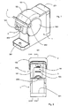
- FIG. 1 is a perspective view of the machine according to the present invention; the machine comprises a base support frame 1 and a box-like body 2 for containing the components of the machine, provided with a water tank 401, and a compartment 10 in which it is possible to position the container for collecting the beverage that will be prepared. with the said machine.
- the head 102 of the box-like body 2 contains the beverage dispensing assembly, which comprises the pressurized water supply means, not shown in the figure and better described below, and the removable filter-holder means 3, in which the dose of edible material, typically in powder form, which will be infused or dissolved by pressurized water, hot or at room temperature.
- the lever 112 as will become better to follow, allows the temporary coupling between the feeding means and the filter-holder means, while on the upper portion of the frame the pushbuttons 202 are visible, which allow the command and control of the machine.
- the machine has a front compartment 10 ', used to receive the container for collecting the beverage produced, with a significantly increased volume compared to the compartment 10 shown in figure 1 .
- This increase in volume of the compartment 10' is the result of the displacement upwardly of the ceiling wall of said compartment, which comprises the dispensing assembly of the machine, and in particular the filter-holder means 3.
- the other walls comprising the compartment 10 or 10 ' are the side walls 11, the back wall 12 and the base platform 301.
- the upward displacement has been possible thanks to the flaps 201 which slide into the wall 101 of the base frame 1.
- the locking means 211 and 221 respectively allow to position the machine in such a way as to form the space 10 'or 10, i.e. to accommodate larger, or smaller, cups inside.
- the whole box-like body 2, including the tank 401 is lifted integrally to the head 102, which contains the dispensing assembly.
- the section of Figure 3 illustrates the coupling mechanism of the supply means 302 with the filter-holder means 3, which comprises the lever 112 coupled by the pin 122 to the arm 312.
- the supply means 302 comprise the shower 402 which pours the pressurized water , coming from the conduit 322, inside the prepacked charge 20, provided with a delivery nozzle 21.
- the filter holder 3 comprises a handle 103 and a containment chamber 203, provided with an opening 213 in the center of its bottom.
- the machine further comprises an electronic circuitry 212 on which the pushbuttons 202 act and which allows to manage both the pump 602 connected to the tank 401 and the boiler 502, drawn by stroke and point in the figure.
- FIG. 4 illustrates a second embodiment of the machine according to the present invention.
- the machine comprises a tank 404 coupled to a box-like body 4 for containing the components of the machine, which comprises a head 104 which in turn comprises the dispensing assembly, consisting of the pressurized water supply means and the filter-holder means 5; on the head 104 are the command and control buttons 204 of the machine.
- a compartment 40 for receiving the means for collecting the prepared beverage is formed by the side walls 41, the bottom wall 42, the ceiling wall constituted by the filter-holder means 5 and by the base platform 304.
- the head 104 of the machine is raised with respect to the platform 304, thanks to the fact that the flaps 524 are provided which slide telescopically into the lateral uprights 504 of the frame 4. the locking means 514 to allow positioning of the head 104 in one of the two configurations shown respectively in Figure 4 or 5 .
- the compartment 40 ' is clearly provided with a larger volume than the space 40, and is therefore able to accommodate bigger cups.
- the rest of the machine body remained integral with the base platform 304.
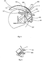
- the section of Figure 6 shows the positioning of the boiler 504, equipped with the water pipe 514 and the resistances 524, inside the head 104, and its direct coupling with the lever 114 through the pin 124; the feeding shower is the one indicated with 402 in figures 3 , and already described above.
- the filter-holder 5 comprises a handle 105, a containment chamber 205 in which a prepacked charge is inserted, which is also perforated in its bottom wall by means of the tip 225; the flow of fluid follows the conduit 235.
- This system of perforation of the prepacked charge is known from the European patent 1723047 , of which the applicant is the inventor.
- the machine comprises the pump 604, which is connected, as well as the boiler 504, to the control electronics 214, controlled by the buttons 204.
- Figure 7 illustrates an executive variant of the machine illustrated in Figures 4 and 5 ; to the equal parts correspond equal numerals.
- the actuating means 714 for moving the head 104 with respect to the base platform 304 are arranged in the rear wall of the head itself.
- the box-like body is provided, in this variant, with a cavity 704, which makes such actuating means 714 accessible when the machine is in its configuration corresponding to that shown in Figure 4 .
- FIG 8 illustrates the filter holder 7, in which a basket 50 can be used for introducing loose coffee powder into the filter holder 7.
- the basket 50 is preferably made of metallic material and provided on the bottom wall of the micro-holes 51 , which allow the percolation of the infusion but not the passage of dust.
- the filter holder comprises a handle 107, a cavity 207 for housing the basket provided on the bottom of a membrane of elastomeric material 217 axially provided with a hole 227, which allows the passage of the infusion towards the delivery conduit 307.
- the membrane has the function of promoting the formation of coffee cream, as it results from Italian patent No. 1314511 of the same applicant.
- the machine is thus able to house different types of collection containers in the compartment intended for them, and is also suitable for operating with different filter-holder means used to make the various types of drinks.
- a machine of this type is extremely compact, and in its closed configuration considerably reduces the space required for storage and shipping.
Landscapes
- Engineering & Computer Science (AREA)
- Food Science & Technology (AREA)
- Apparatus For Making Beverages (AREA)
- Devices For Dispensing Beverages (AREA)
- Tea And Coffee (AREA)
Abstract
Description
- The present invention relates to the household appliances, and particularly it relates to a machine for the preparation of beverages.
- The machine in question is preferably designed to provide the user with a versatile, economical and small-scale apparatus, which is able to provide beverages of various types, preferably but not necessarily hot, made by infusion or dissolution of a substance contained in a removable filter holder, in the form of bulk as well as in the form of a prepacked charge.
- A machine that has this kind of versatility cannot currently be small, since at least it must adapt to the use of more capacious containers (the so-called "mugs"), as well as that of espresso cups. In many machines, a very large positioning space is now provided for the container for the beverage, which is then divided by means of an oscillating shelf, which can be locked in the open position, so as to define a support position for the container nearest the dispensing nozzle, and therefore more suitable for smaller containers.
- Naturally, this type of support of a temporary nature, if it is well suited to plastic cups or "disposable" material, is not as reliable for the ceramic cups, which are normally quite heavy.
- The particular construction of the removable filter holder allows a wide range of possible uses; moreover, the coupling movement between the pressure water supply unit is designed in such a way as to contribute to the overall saving of space in the construction of the present machine.
- The aim of the present invention is therefore to provide a beverage preparation machine which is extremely versatile in its own applications, and which is both small in size and simple and economical to produce.
- An object of the present invention is therefore a machine for preparing beverages, comprising a water tank, a box-like body housing a boiler, a pump and control and command means, and a beverage dispensing assembly located in the head of the said box body; said machine being provided frontally with a compartment for positioning a collection container for the prepared beverage, said compartment being comprised between a base platform, two side walls, a rear wall, and a ceiling wall, comprising the beverage dispensing assembly, in turn comprising pressure water supply means and removable filter-holder means, wherein said beverage dispensing assembly is mounted movable with respect to the base platform of said cavity and may be arranged in a position closer and further away from said platform, suitable guide and locking means being provided, thus allowing a substantial increase in volume to said compartment.
- In an embodiment, said locking means are located along the side walls of the box-like body, and are controlled by actuating means arranged in the same way on the side walls; alternatively, the actuating means can be positioned on the upper wall of the box-like body. The guide means comprise substantial portions of the side walls of the machine provided telescopically sliding inside one another.
- A further object of the present invention is a beverage preparation machine comprising pressurized water supply means, and removable filter-holder means for introducing the substance to be infused or dissolved, wherein the coupling between said supply means and said filter-holder means is conducted by shifting, with a suitable kinematic mechanism, typically a snap mechanism, the unit for feeding hot water under pressure from a position of non-coupling to a coupling position, and vice versa. Moreover, in an embodiment, the boiler is arranged in the movable portion of said machine.
- The machine may also be provided with a plurality of interchangeable filter holders, capable of accommodating both prepacked charges and filter means as containers for loose substances.
- Further advantages and features of the machine according to the present invention will become apparent from the following detailed description of some embodiments thereof, performed, by way of non-limiting example, with reference to the attached drawings, in which:
-
Figure 1 is a perspective view of an embodiment of the machine according to the present invention, in a first configuration; -
Figure 2 shows the machine ofFigure 1 in a second configuration; -
Figure 3 is a longitudinal section view of the machine ofFigure 1 ; -
Figure 4 is a perspective view of a second embodiment of the machine according to the invention, in a first configuration; -
Figure 5 shows the machine ofFigure 4 in a second configuration; -
Figure 6 is a longitudinal section view of the machine ofFigure 4 ; -
Figure 7 is a perspective view of a variant embodiment of the machine illustrated inFigures 4 and5 ; -
Figure 8 is a longitudinal sectional view of a detail concerning a further embodiment of the machine according to the present invention. -
Figure 1 is a perspective view of the machine according to the present invention; the machine comprises abase support frame 1 and a box-like body 2 for containing the components of the machine, provided with awater tank 401, and a compartment 10 in which it is possible to position the container for collecting the beverage that will be prepared. with the said machine. Thehead 102 of the box-like body 2 contains the beverage dispensing assembly, which comprises the pressurized water supply means, not shown in the figure and better described below, and the removable filter-holder means 3, in which the dose of edible material, typically in powder form, which will be infused or dissolved by pressurized water, hot or at room temperature. The lever 112, as will become better to follow, allows the temporary coupling between the feeding means and the filter-holder means, while on the upper portion of the frame thepushbuttons 202 are visible, which allow the command and control of the machine. - In
figure 2 the machine has a front compartment 10 ', used to receive the container for collecting the beverage produced, with a significantly increased volume compared to the compartment 10 shown infigure 1 . This increase in volume of the compartment 10' is the result of the displacement upwardly of the ceiling wall of said compartment, which comprises the dispensing assembly of the machine, and in particular the filter-holder means 3. The other walls comprising the compartment 10 or 10 'are the side walls 11, the back wall 12 and thebase platform 301. The upward displacement has been possible thanks to theflaps 201 which slide into thewall 101 of thebase frame 1. The locking means 211 and 221 respectively allow to position the machine in such a way as to form the space 10 'or 10, i.e. to accommodate larger, or smaller, cups inside. The whole box-like body 2, including thetank 401, is lifted integrally to thehead 102, which contains the dispensing assembly. - The section of
Figure 3 illustrates the coupling mechanism of the supply means 302 with the filter-holder means 3, which comprises the lever 112 coupled by the pin 122 to the arm 312. The supply means 302 comprise theshower 402 which pours the pressurized water , coming from the conduit 322, inside the prepacked charge 20, provided with a delivery nozzle 21. Thefilter holder 3 comprises ahandle 103 and acontainment chamber 203, provided with anopening 213 in the center of its bottom. The machine further comprises anelectronic circuitry 212 on which thepushbuttons 202 act and which allows to manage both the pump 602 connected to thetank 401 and the boiler 502, drawn by stroke and point in the figure. -
Figure 4 illustrates a second embodiment of the machine according to the present invention. The machine comprises atank 404 coupled to a box-like body 4 for containing the components of the machine, which comprises ahead 104 which in turn comprises the dispensing assembly, consisting of the pressurized water supply means and the filter-holder means 5; on thehead 104 are the command andcontrol buttons 204 of the machine. At the front the machine is equipped with acompartment 40 for receiving the means for collecting the prepared beverage; the compartment is formed by the side walls 41, the bottom wall 42, the ceiling wall constituted by the filter-holder means 5 and by thebase platform 304. - In the configuration shown in
Figure 5 , in which to the equal parts correspond equal numerals, thehead 104 of the machine is raised with respect to theplatform 304, thanks to the fact that the flaps 524 are provided which slide telescopically into the lateral uprights 504 of theframe 4. the locking means 514 to allow positioning of thehead 104 in one of the two configurations shown respectively inFigure 4 or5 . The compartment 40 'is clearly provided with a larger volume than thespace 40, and is therefore able to accommodate bigger cups. The rest of the machine body remained integral with thebase platform 304. - The section of
Figure 6 shows the positioning of the boiler 504, equipped with the water pipe 514 and the resistances 524, inside thehead 104, and its direct coupling with the lever 114 through the pin 124; the feeding shower is the one indicated with 402 infigures 3 , and already described above. The filter-holder 5 comprises ahandle 105, acontainment chamber 205 in which a prepacked charge is inserted, which is also perforated in its bottom wall by means of the tip 225; the flow of fluid follows the conduit 235. This system of perforation of the prepacked charge is known from theEuropean patent 1723047 , of which the applicant is the inventor. In addition to thetank 404, the machine comprises the pump 604, which is connected, as well as the boiler 504, to the control electronics 214, controlled by thebuttons 204. -
Figure 7 illustrates an executive variant of the machine illustrated inFigures 4 and5 ; to the equal parts correspond equal numerals. In the figure it can be seen that the actuating means 714 for moving thehead 104 with respect to thebase platform 304 are arranged in the rear wall of the head itself. The box-like body is provided, in this variant, with a cavity 704, which makes such actuating means 714 accessible when the machine is in its configuration corresponding to that shown inFigure 4 . - Finally,
Figure 8 illustrates thefilter holder 7, in which a basket 50 can be used for introducing loose coffee powder into thefilter holder 7. The basket 50 is preferably made of metallic material and provided on the bottom wall of the micro-holes 51 , which allow the percolation of the infusion but not the passage of dust. The filter holder comprises ahandle 107, acavity 207 for housing the basket provided on the bottom of a membrane of elastomeric material 217 axially provided with a hole 227, which allows the passage of the infusion towards thedelivery conduit 307. The membrane has the function of promoting the formation of coffee cream, as it results from Italian patent No.1314511 - In this way the machine is thus able to house different types of collection containers in the compartment intended for them, and is also suitable for operating with different filter-holder means used to make the various types of drinks. Moreover, a machine of this type is extremely compact, and in its closed configuration considerably reduces the space required for storage and shipping.
Claims (6)
- A machine for preparing beverages, comprising a water tank (401; 404), a box-like body (1, 2; 4) which houses a boiler (502; 504), a pump (602; 604) and control means (212; 214), and a beverage dispensing unit placed in the head (102; 104) of said box-like body (1, 2; 4), said machine being fitted frontally with a compartment (10; 40) for the placement of a collection container for the prepared drink, said compartment (10; 40) being comprised between a base platform (301; 304), two side walls (11; 41), a rear wall (12; 42), and a ceiling wall, comprising the dispensing unit of the drink, in turn comprising supply means (402) of water under pressure and removable filter holder means (3; 5; 7), wherein said group of beverage dispensing is mounted movable relative to the base platform of said cavity and can be disposed in a position closer and in a more distant position with respect to said platform, there being provided suitable guide means (101, 201; 504 ; 524) and the locking means (211, 221; 514), being allowed in this manner to said chamber (10; 40) a substantial increase in volume (10 '; 40').
- Machine according to claim 1, wherein said locking means (211, 221; 514) are placed along the side walls (101; 501), and are controlled through actuating means arranged likewise on said side walls.
- Machine according to claim 1, wherein said actuating means (714) of said locking means are arranged on the upper wall of said box-like body (4), close to said head (104).
- Machine according to any of the preceding claims 1 to 3, wherein the guide means comprise substantial portions of the side walls (101, 201; 504; 524) of the said box-like body (1.2; 4) of the machine, provided telescopically sliding inside one another.
- Machine according to any of the preceding claims 1 to 3, wherein said head (104) is movable relative to the rest of said box-like body (4).
- Machine according to any of the preceding claims 1 to 5, provided with a plurality of filter holders (3; 5; 7) interchangeable between them, able to accommodate both prepackaged charges and filter means as containers for bulk substances.
Applications Claiming Priority (1)
| Application Number | Priority Date | Filing Date | Title |
|---|---|---|---|
| IT102017000014508A IT201700014508A1 (en) | 2017-02-09 | 2017-02-09 | Beverage preparation machine |
Publications (2)
| Publication Number | Publication Date |
|---|---|
| EP3360449A1 true EP3360449A1 (en) | 2018-08-15 |
| EP3360449B1 EP3360449B1 (en) | 2020-04-08 |
Family
ID=59067778
Family Applications (1)
| Application Number | Title | Priority Date | Filing Date |
|---|---|---|---|
| EP18000097.8A Not-in-force EP3360449B1 (en) | 2017-02-09 | 2018-02-06 | Beverage machine |
Country Status (2)
| Country | Link |
|---|---|
| EP (1) | EP3360449B1 (en) |
| IT (1) | IT201700014508A1 (en) |
Cited By (2)
| Publication number | Priority date | Publication date | Assignee | Title |
|---|---|---|---|---|
| CN109549490A (en) * | 2019-01-28 | 2019-04-02 | 珠海格力电器股份有限公司 | Electrical equipment with heating function and method thereof |
| CN109924876A (en) * | 2019-04-24 | 2019-06-25 | 曾剑煌 | The water dispenser that a kind of settable water and separation are heated up water |
Citations (4)
| Publication number | Priority date | Publication date | Assignee | Title |
|---|---|---|---|---|
| US20060266223A1 (en) * | 2005-05-25 | 2006-11-30 | Jamal Hammad | Single serve beverage maker with adjustable brew head |
| CN201612511U (en) * | 2010-01-20 | 2010-10-27 | 唐玉霖 | water dispenser |
| WO2013128323A2 (en) * | 2012-03-01 | 2013-09-06 | Koninklijke Philips N.V. | Beverage producing machine with adjustable dispensing nozzle |
| US20140021227A1 (en) * | 2011-02-07 | 2014-01-23 | Bravilor Holding B.V. | Beverage Preparation Device Provided With A Discharge That Is Height-Adjustable By Hand |
-
2017
- 2017-02-09 IT IT102017000014508A patent/IT201700014508A1/en unknown
-
2018
- 2018-02-06 EP EP18000097.8A patent/EP3360449B1/en not_active Not-in-force
Patent Citations (4)
| Publication number | Priority date | Publication date | Assignee | Title |
|---|---|---|---|---|
| US20060266223A1 (en) * | 2005-05-25 | 2006-11-30 | Jamal Hammad | Single serve beverage maker with adjustable brew head |
| CN201612511U (en) * | 2010-01-20 | 2010-10-27 | 唐玉霖 | water dispenser |
| US20140021227A1 (en) * | 2011-02-07 | 2014-01-23 | Bravilor Holding B.V. | Beverage Preparation Device Provided With A Discharge That Is Height-Adjustable By Hand |
| WO2013128323A2 (en) * | 2012-03-01 | 2013-09-06 | Koninklijke Philips N.V. | Beverage producing machine with adjustable dispensing nozzle |
Cited By (2)
| Publication number | Priority date | Publication date | Assignee | Title |
|---|---|---|---|---|
| CN109549490A (en) * | 2019-01-28 | 2019-04-02 | 珠海格力电器股份有限公司 | Electrical equipment with heating function and method thereof |
| CN109924876A (en) * | 2019-04-24 | 2019-06-25 | 曾剑煌 | The water dispenser that a kind of settable water and separation are heated up water |
Also Published As
| Publication number | Publication date |
|---|---|
| EP3360449B1 (en) | 2020-04-08 |
| IT201700014508A1 (en) | 2018-08-09 |
Similar Documents
| Publication | Publication Date | Title |
|---|---|---|
| EP2645913B1 (en) | Ergonomic user-interface for motorised ingredient chamber | |
| EP2613676B1 (en) | Ergonomic handle with user-interface | |
| EP2802244B1 (en) | Beverage machine for short and tall cups | |
| EP2645908B1 (en) | Beverage machine having a capsule passage with a gate | |
| EP3277135B1 (en) | Shallow machine | |
| KR102647459B1 (en) | System for manufacturing multi-ingredient beverages from various container types | |
| EP3277136B1 (en) | A machine for dispensing a beverage comprising an interface with safety cover | |
| JP2018526084A (en) | Beverage machine with ergonomic outlet | |
| CN110313831B (en) | Beverage preparation machine | |
| KR102218826B1 (en) | Dual beverage extracting apparatus | |
| EP3727110B1 (en) | Beverage preparation machine with handy drop stop | |
| EP3360449B1 (en) | Beverage machine | |
| AU2018387158A1 (en) | Beverage preparation machine with foam refinement | |
| EP3277138B1 (en) | Locking cup support | |
| EP3727109B1 (en) | Beverage preparation machine with drop evacuation | |
| US20240407586A1 (en) | Ergonomic beverage machine | |
| CN101237800A (en) | Beverage brewing device with movable spout | |
| CN101237799A (en) | Beverage brewing device with removable reservoir | |
| EP3277139B1 (en) | Slidable cup support | |
| KR20210046988A (en) | beverage extracting apparatus | |
| KR20210046987A (en) | Dual beverage extracting apparatus | |
| EP2832271A1 (en) | Machine for making an infused drink | |
| ITBS20120007U1 (en) | MACHINE FOR PREPARATION AND DELIVERY OF DRINKS |
Legal Events
| Date | Code | Title | Description |
|---|---|---|---|
| PUAI | Public reference made under article 153(3) epc to a published international application that has entered the european phase |
Free format text: ORIGINAL CODE: 0009012 |
|
| STAA | Information on the status of an ep patent application or granted ep patent |
Free format text: STATUS: THE APPLICATION HAS BEEN PUBLISHED |
|
| AK | Designated contracting states |
Kind code of ref document: A1 Designated state(s): AL AT BE BG CH CY CZ DE DK EE ES FI FR GB GR HR HU IE IS IT LI LT LU LV MC MK MT NL NO PL PT RO RS SE SI SK SM TR |
|
| AX | Request for extension of the european patent |
Extension state: BA ME |
|
| STAA | Information on the status of an ep patent application or granted ep patent |
Free format text: STATUS: REQUEST FOR EXAMINATION WAS MADE |
|
| 17P | Request for examination filed |
Effective date: 20190212 |
|
| RBV | Designated contracting states (corrected) |
Designated state(s): AL AT BE BG CH CY CZ DE DK EE ES FI FR GB GR HR HU IE IS IT LI LT LU LV MC MK MT NL NO PL PT RO RS SE SI SK SM TR |
|
| GRAP | Despatch of communication of intention to grant a patent |
Free format text: ORIGINAL CODE: EPIDOSNIGR1 |
|
| STAA | Information on the status of an ep patent application or granted ep patent |
Free format text: STATUS: GRANT OF PATENT IS INTENDED |
|
| INTG | Intention to grant announced |
Effective date: 20190916 |
|
| GRAS | Grant fee paid |
Free format text: ORIGINAL CODE: EPIDOSNIGR3 |
|
| GRAA | (expected) grant |
Free format text: ORIGINAL CODE: 0009210 |
|
| STAA | Information on the status of an ep patent application or granted ep patent |
Free format text: STATUS: THE PATENT HAS BEEN GRANTED |
|
| AK | Designated contracting states |
Kind code of ref document: B1 Designated state(s): AL AT BE BG CH CY CZ DE DK EE ES FI FR GB GR HR HU IE IS IT LI LT LU LV MC MK MT NL NO PL PT RO RS SE SI SK SM TR |
|
| REG | Reference to a national code |
Ref country code: AT Ref legal event code: REF Ref document number: 1253197 Country of ref document: AT Kind code of ref document: T Effective date: 20200415 Ref country code: CH Ref legal event code: EP |
|
| REG | Reference to a national code |
Ref country code: DE Ref legal event code: R096 Ref document number: 602018003459 Country of ref document: DE |
|
| REG | Reference to a national code |
Ref country code: IE Ref legal event code: FG4D |
|
| REG | Reference to a national code |
Ref country code: NL Ref legal event code: MP Effective date: 20200408 |
|
| REG | Reference to a national code |
Ref country code: LT Ref legal event code: MG4D |
|
| PG25 | Lapsed in a contracting state [announced via postgrant information from national office to epo] |
Ref country code: LT Free format text: LAPSE BECAUSE OF FAILURE TO SUBMIT A TRANSLATION OF THE DESCRIPTION OR TO PAY THE FEE WITHIN THE PRESCRIBED TIME-LIMIT Effective date: 20200408 Ref country code: FI Free format text: LAPSE BECAUSE OF FAILURE TO SUBMIT A TRANSLATION OF THE DESCRIPTION OR TO PAY THE FEE WITHIN THE PRESCRIBED TIME-LIMIT Effective date: 20200408 Ref country code: NL Free format text: LAPSE BECAUSE OF FAILURE TO SUBMIT A TRANSLATION OF THE DESCRIPTION OR TO PAY THE FEE WITHIN THE PRESCRIBED TIME-LIMIT Effective date: 20200408 Ref country code: GR Free format text: LAPSE BECAUSE OF FAILURE TO SUBMIT A TRANSLATION OF THE DESCRIPTION OR TO PAY THE FEE WITHIN THE PRESCRIBED TIME-LIMIT Effective date: 20200709 Ref country code: NO Free format text: LAPSE BECAUSE OF FAILURE TO SUBMIT A TRANSLATION OF THE DESCRIPTION OR TO PAY THE FEE WITHIN THE PRESCRIBED TIME-LIMIT Effective date: 20200708 Ref country code: IS Free format text: LAPSE BECAUSE OF FAILURE TO SUBMIT A TRANSLATION OF THE DESCRIPTION OR TO PAY THE FEE WITHIN THE PRESCRIBED TIME-LIMIT Effective date: 20200808 Ref country code: PT Free format text: LAPSE BECAUSE OF FAILURE TO SUBMIT A TRANSLATION OF THE DESCRIPTION OR TO PAY THE FEE WITHIN THE PRESCRIBED TIME-LIMIT Effective date: 20200817 Ref country code: SE Free format text: LAPSE BECAUSE OF FAILURE TO SUBMIT A TRANSLATION OF THE DESCRIPTION OR TO PAY THE FEE WITHIN THE PRESCRIBED TIME-LIMIT Effective date: 20200408 |
|
| REG | Reference to a national code |
Ref country code: AT Ref legal event code: MK05 Ref document number: 1253197 Country of ref document: AT Kind code of ref document: T Effective date: 20200408 |
|
| PG25 | Lapsed in a contracting state [announced via postgrant information from national office to epo] |
Ref country code: RS Free format text: LAPSE BECAUSE OF FAILURE TO SUBMIT A TRANSLATION OF THE DESCRIPTION OR TO PAY THE FEE WITHIN THE PRESCRIBED TIME-LIMIT Effective date: 20200408 Ref country code: HR Free format text: LAPSE BECAUSE OF FAILURE TO SUBMIT A TRANSLATION OF THE DESCRIPTION OR TO PAY THE FEE WITHIN THE PRESCRIBED TIME-LIMIT Effective date: 20200408 Ref country code: LV Free format text: LAPSE BECAUSE OF FAILURE TO SUBMIT A TRANSLATION OF THE DESCRIPTION OR TO PAY THE FEE WITHIN THE PRESCRIBED TIME-LIMIT Effective date: 20200408 Ref country code: BG Free format text: LAPSE BECAUSE OF FAILURE TO SUBMIT A TRANSLATION OF THE DESCRIPTION OR TO PAY THE FEE WITHIN THE PRESCRIBED TIME-LIMIT Effective date: 20200708 |
|
| PG25 | Lapsed in a contracting state [announced via postgrant information from national office to epo] |
Ref country code: AL Free format text: LAPSE BECAUSE OF FAILURE TO SUBMIT A TRANSLATION OF THE DESCRIPTION OR TO PAY THE FEE WITHIN THE PRESCRIBED TIME-LIMIT Effective date: 20200408 |
|
| REG | Reference to a national code |
Ref country code: DE Ref legal event code: R097 Ref document number: 602018003459 Country of ref document: DE |
|
| PG25 | Lapsed in a contracting state [announced via postgrant information from national office to epo] |
Ref country code: DK Free format text: LAPSE BECAUSE OF FAILURE TO SUBMIT A TRANSLATION OF THE DESCRIPTION OR TO PAY THE FEE WITHIN THE PRESCRIBED TIME-LIMIT Effective date: 20200408 Ref country code: EE Free format text: LAPSE BECAUSE OF FAILURE TO SUBMIT A TRANSLATION OF THE DESCRIPTION OR TO PAY THE FEE WITHIN THE PRESCRIBED TIME-LIMIT Effective date: 20200408 Ref country code: SM Free format text: LAPSE BECAUSE OF FAILURE TO SUBMIT A TRANSLATION OF THE DESCRIPTION OR TO PAY THE FEE WITHIN THE PRESCRIBED TIME-LIMIT Effective date: 20200408 Ref country code: RO Free format text: LAPSE BECAUSE OF FAILURE TO SUBMIT A TRANSLATION OF THE DESCRIPTION OR TO PAY THE FEE WITHIN THE PRESCRIBED TIME-LIMIT Effective date: 20200408 Ref country code: AT Free format text: LAPSE BECAUSE OF FAILURE TO SUBMIT A TRANSLATION OF THE DESCRIPTION OR TO PAY THE FEE WITHIN THE PRESCRIBED TIME-LIMIT Effective date: 20200408 Ref country code: ES Free format text: LAPSE BECAUSE OF FAILURE TO SUBMIT A TRANSLATION OF THE DESCRIPTION OR TO PAY THE FEE WITHIN THE PRESCRIBED TIME-LIMIT Effective date: 20200408 Ref country code: IT Free format text: LAPSE BECAUSE OF FAILURE TO SUBMIT A TRANSLATION OF THE DESCRIPTION OR TO PAY THE FEE WITHIN THE PRESCRIBED TIME-LIMIT Effective date: 20200408 Ref country code: CZ Free format text: LAPSE BECAUSE OF FAILURE TO SUBMIT A TRANSLATION OF THE DESCRIPTION OR TO PAY THE FEE WITHIN THE PRESCRIBED TIME-LIMIT Effective date: 20200408 |
|
| PLBE | No opposition filed within time limit |
Free format text: ORIGINAL CODE: 0009261 |
|
| STAA | Information on the status of an ep patent application or granted ep patent |
Free format text: STATUS: NO OPPOSITION FILED WITHIN TIME LIMIT |
|
| PG25 | Lapsed in a contracting state [announced via postgrant information from national office to epo] |
Ref country code: SK Free format text: LAPSE BECAUSE OF FAILURE TO SUBMIT A TRANSLATION OF THE DESCRIPTION OR TO PAY THE FEE WITHIN THE PRESCRIBED TIME-LIMIT Effective date: 20200408 Ref country code: PL Free format text: LAPSE BECAUSE OF FAILURE TO SUBMIT A TRANSLATION OF THE DESCRIPTION OR TO PAY THE FEE WITHIN THE PRESCRIBED TIME-LIMIT Effective date: 20200408 |
|
| 26N | No opposition filed |
Effective date: 20210112 |
|
| PG25 | Lapsed in a contracting state [announced via postgrant information from national office to epo] |
Ref country code: SI Free format text: LAPSE BECAUSE OF FAILURE TO SUBMIT A TRANSLATION OF THE DESCRIPTION OR TO PAY THE FEE WITHIN THE PRESCRIBED TIME-LIMIT Effective date: 20200408 |
|
| PG25 | Lapsed in a contracting state [announced via postgrant information from national office to epo] |
Ref country code: MC Free format text: LAPSE BECAUSE OF FAILURE TO SUBMIT A TRANSLATION OF THE DESCRIPTION OR TO PAY THE FEE WITHIN THE PRESCRIBED TIME-LIMIT Effective date: 20200408 |
|
| REG | Reference to a national code |
Ref country code: BE Ref legal event code: MM Effective date: 20210228 |
|
| PG25 | Lapsed in a contracting state [announced via postgrant information from national office to epo] |
Ref country code: CH Free format text: LAPSE BECAUSE OF NON-PAYMENT OF DUE FEES Effective date: 20210228 Ref country code: LU Free format text: LAPSE BECAUSE OF NON-PAYMENT OF DUE FEES Effective date: 20210206 Ref country code: LI Free format text: LAPSE BECAUSE OF NON-PAYMENT OF DUE FEES Effective date: 20210228 |
|
| PG25 | Lapsed in a contracting state [announced via postgrant information from national office to epo] |
Ref country code: IE Free format text: LAPSE BECAUSE OF NON-PAYMENT OF DUE FEES Effective date: 20210206 Ref country code: FR Free format text: LAPSE BECAUSE OF NON-PAYMENT OF DUE FEES Effective date: 20210228 |
|
| PG25 | Lapsed in a contracting state [announced via postgrant information from national office to epo] |
Ref country code: BE Free format text: LAPSE BECAUSE OF NON-PAYMENT OF DUE FEES Effective date: 20210228 |
|
| GBPC | Gb: european patent ceased through non-payment of renewal fee |
Effective date: 20220206 |
|
| PG25 | Lapsed in a contracting state [announced via postgrant information from national office to epo] |
Ref country code: GB Free format text: LAPSE BECAUSE OF NON-PAYMENT OF DUE FEES Effective date: 20220206 |
|
| PGFP | Annual fee paid to national office [announced via postgrant information from national office to epo] |
Ref country code: DE Payment date: 20230223 Year of fee payment: 6 |
|
| PG25 | Lapsed in a contracting state [announced via postgrant information from national office to epo] |
Ref country code: CY Free format text: LAPSE BECAUSE OF FAILURE TO SUBMIT A TRANSLATION OF THE DESCRIPTION OR TO PAY THE FEE WITHIN THE PRESCRIBED TIME-LIMIT Effective date: 20200408 |
|
| P01 | Opt-out of the competence of the unified patent court (upc) registered |
Effective date: 20230605 |
|
| PG25 | Lapsed in a contracting state [announced via postgrant information from national office to epo] |
Ref country code: HU Free format text: LAPSE BECAUSE OF FAILURE TO SUBMIT A TRANSLATION OF THE DESCRIPTION OR TO PAY THE FEE WITHIN THE PRESCRIBED TIME-LIMIT; INVALID AB INITIO Effective date: 20180206 |
|
| PG25 | Lapsed in a contracting state [announced via postgrant information from national office to epo] |
Ref country code: MK Free format text: LAPSE BECAUSE OF FAILURE TO SUBMIT A TRANSLATION OF THE DESCRIPTION OR TO PAY THE FEE WITHIN THE PRESCRIBED TIME-LIMIT Effective date: 20200408 |
|
| REG | Reference to a national code |
Ref country code: DE Ref legal event code: R119 Ref document number: 602018003459 Country of ref document: DE |
|
| PG25 | Lapsed in a contracting state [announced via postgrant information from national office to epo] |
Ref country code: MT Free format text: LAPSE BECAUSE OF FAILURE TO SUBMIT A TRANSLATION OF THE DESCRIPTION OR TO PAY THE FEE WITHIN THE PRESCRIBED TIME-LIMIT Effective date: 20200408 |
|
| PG25 | Lapsed in a contracting state [announced via postgrant information from national office to epo] |
Ref country code: DE Free format text: LAPSE BECAUSE OF NON-PAYMENT OF DUE FEES Effective date: 20240903 |
|
| PG25 | Lapsed in a contracting state [announced via postgrant information from national office to epo] |
Ref country code: DE Free format text: LAPSE BECAUSE OF NON-PAYMENT OF DUE FEES Effective date: 20240903 |
|
| PG25 | Lapsed in a contracting state [announced via postgrant information from national office to epo] |
Ref country code: TR Free format text: LAPSE BECAUSE OF FAILURE TO SUBMIT A TRANSLATION OF THE DESCRIPTION OR TO PAY THE FEE WITHIN THE PRESCRIBED TIME-LIMIT Effective date: 20200408 |