EP3360402B2 - Row planter unit with sensor-mounted furrow shaper - Google Patents
Row planter unit with sensor-mounted furrow shaper Download PDFInfo
- Publication number
- EP3360402B2 EP3360402B2 EP18151092.6A EP18151092A EP3360402B2 EP 3360402 B2 EP3360402 B2 EP 3360402B2 EP 18151092 A EP18151092 A EP 18151092A EP 3360402 B2 EP3360402 B2 EP 3360402B2
- Authority
- EP
- European Patent Office
- Prior art keywords
- furrow
- foot
- sensor
- row unit
- seed
- Prior art date
- Legal status (The legal status is an assumption and is not a legal conclusion. Google has not performed a legal analysis and makes no representation as to the accuracy of the status listed.)
- Active
Links
- 230000007246 mechanism Effects 0.000 claims description 17
- 239000002689 soil Substances 0.000 claims description 12
- 239000000463 material Substances 0.000 description 12
- 239000004699 Ultra-high molecular weight polyethylene Substances 0.000 description 4
- 239000012778 molding material Substances 0.000 description 4
- 238000004382 potting Methods 0.000 description 4
- 229920000785 ultra high molecular weight polyethylene Polymers 0.000 description 4
- 239000004033 plastic Substances 0.000 description 3
- 229920003023 plastic Polymers 0.000 description 3
- IJGRMHOSHXDMSA-UHFFFAOYSA-N Atomic nitrogen Chemical compound N#N IJGRMHOSHXDMSA-UHFFFAOYSA-N 0.000 description 2
- 239000000853 adhesive Substances 0.000 description 2
- 230000001070 adhesive effect Effects 0.000 description 2
- 239000000919 ceramic Substances 0.000 description 2
- 229910010293 ceramic material Inorganic materials 0.000 description 2
- 229910002085 magnesia-stabilized zirconia Inorganic materials 0.000 description 2
- 239000012811 non-conductive material Substances 0.000 description 2
- 238000010899 nucleation Methods 0.000 description 2
- 230000003287 optical effect Effects 0.000 description 2
- PZBPKYOVPCNPJY-UHFFFAOYSA-N 1-[2-(allyloxy)-2-(2,4-dichlorophenyl)ethyl]imidazole Chemical compound ClC1=CC(Cl)=CC=C1C(OCC=C)CN1C=NC=C1 PZBPKYOVPCNPJY-UHFFFAOYSA-N 0.000 description 1
- 230000005540 biological transmission Effects 0.000 description 1
- 239000004927 clay Substances 0.000 description 1
- 238000004891 communication Methods 0.000 description 1
- 230000003750 conditioning effect Effects 0.000 description 1
- 238000010276 construction Methods 0.000 description 1
- 230000001419 dependent effect Effects 0.000 description 1
- 230000008021 deposition Effects 0.000 description 1
- 230000035558 fertility Effects 0.000 description 1
- 239000002184 metal Substances 0.000 description 1
- 229910052757 nitrogen Inorganic materials 0.000 description 1
- 235000021049 nutrient content Nutrition 0.000 description 1
- 239000005416 organic matter Substances 0.000 description 1
- 230000000717 retained effect Effects 0.000 description 1
- 238000001228 spectrum Methods 0.000 description 1
- 238000001931 thermography Methods 0.000 description 1
Images


Classifications
-
- A—HUMAN NECESSITIES
- A01—AGRICULTURE; FORESTRY; ANIMAL HUSBANDRY; HUNTING; TRAPPING; FISHING
- A01C—PLANTING; SOWING; FERTILISING
- A01C7/00—Sowing
- A01C7/08—Broadcast seeders; Seeders depositing seeds in rows
-
- A—HUMAN NECESSITIES
- A01—AGRICULTURE; FORESTRY; ANIMAL HUSBANDRY; HUNTING; TRAPPING; FISHING
- A01C—PLANTING; SOWING; FERTILISING
- A01C5/00—Making or covering furrows or holes for sowing, planting or manuring
- A01C5/06—Machines for making or covering drills or furrows for sowing or planting
- A01C5/062—Devices for making drills or furrows
- A01C5/064—Devices for making drills or furrows with rotating tools
-
- A—HUMAN NECESSITIES
- A01—AGRICULTURE; FORESTRY; ANIMAL HUSBANDRY; HUNTING; TRAPPING; FISHING
- A01C—PLANTING; SOWING; FERTILISING
- A01C7/00—Sowing
- A01C7/20—Parts of seeders for conducting and depositing seed
- A01C7/201—Mounting of the seeding tools
- A01C7/203—Mounting of the seeding tools comprising depth regulation means
Definitions
- the present disclosure relates to a planter row unit, and more particularly to a planter row unit with a furrow shaper.
- a planter typically has several planter row units. Each planter row unit is configured to plant seed in the ground as the planter is pulled or otherwise moved in a planting direction of travel.
- the row unit has a furrow opener to open a furrow, a furrow closer to close the furrow, and a seed delivery mechanism to deposit seed into the furrow before it is closed.
- a row unit has a furrow shaper to shape the furrow ahead of deposition of seed into the furrow relative to the planting direction of travel.
- the furrow opener sometimes forms the furrow with a W-shaped cross-section lateral to the planting direction of travel.
- the furrow shaper comes along behind the furrow opener to shape the furrow without the middle peak of the W shape to prepare the furrow for reception of seed.
- EP 3 150 045 A1 discloses a sensor element in a furrow opener of an agricultural seeding machine.
- WO 2015/171915 A1 discloses a sensor element in a seed firmer of an agricultural seeding machine.
- the invention is defined by claim 1.
- a planter row unit 10 may be used in a planter having a number of such row units mounted to a toolbar of the planter.
- Each row unit 10 is configured to plant seeds in the ground, as the planter is moved in a planting direction of travel 12 through a field by, for example, a tractor.
- the row unit 10 comprises a frame 14 and a four-bar linkage 16 that mounts the frame 14 to the toolbar.
- the linkage 16 comprises a bracket 18 bolted to the toolbar.
- the row unit 10 comprises a furrow opener 20 mounted to the frame 14 to open a furrow in the ground.
- the furrow opener 20 may comprise two discs 24, one of which is shown, for example, in FIG. 2 , positioned relative to one another to open the furrow.
- the row unit 10 comprises a furrow closer 26 mounted to the frame 14 to close the furrow.
- the furrow closer 26 is positioned rearwardly of the furrow opener 20 relative to the planting direction of travel 12 of the row unit 10.
- the furrow closer 26 may comprise two closing wheels 28 positioned relative to one another to close the furrow.
- the row unit 10 comprises two gauge wheels 30 mounted to and positioned on opposite sides of the frame 14.
- the gauge wheels 30 cooperate to establish the depth of the furrow opener 20 and correspondingly the depth of the furrow.
- the gauge wheels 30 are vertically movable relative to the frame 14 to a stop which sets the furrow depth.
- the row unit 10 comprises a seed delivery mechanism 32 mounted to the frame 14 to deposit seed into the furrow.
- the seed delivery mechanism 32 is positioned between the furrow opener 20 and the furrow closer 26 relative to a planting direction of travel 12 of the row unit 10
- the seed delivery mechanism 32 is included in a seed supply system 36 of the row unit 10.
- the seed supply system 36 comprises a hopper 38 and a vacuum seed meter 40.
- the hopper 38 is configured to receive seed from a source (not shown) via a hopper inlet 42.
- the seed meter 40 is configured to receive seed from the hopper 38, and singulate the seed on respective apertures (not shown) of the meter 40 to which a vacuum pressure is applied.
- the seed delivery mechanism 32 is configured as a brush-belt cartridge.
- the brush-belt cartridge comprises a brush belt 44 (shown diagrammatically) circulating to pick up seed one-by-one from the seed meter 40 and to deliver the seed to a seed outlet 46 of the mechanism 32 where the brush belt 44 releases the seed, which is under centrifugal force as the brush belt 44 makes a turn near the bottom of its cycle.
- the mechanism 32 is configured to deposit each seed into the furrow.
- Other seed delivery mechanisms may be used to deposit seed into the furrow, such as, for example, a seed tube.
- the row unit 10 comprises a furrow shaper 48 mounted to the frame 14.
- the furrow shaper 48 is positioned relative to the furrow opener 20 and the seed delivery mechanism 32 to shape the furrow, opened by the furrow opener 20, ahead of seed deposited into the furrow by the seed delivery mechanism 32 relative to the planting direction of travel 12 of the planter row unit 10.
- the furrow shaper 48 is positioned at least in part between the furrow opener 20 and the seed delivery mechanism 32 relative to the planting direction of travel 12.
- the furrow opener 20 When the furrow opener 20 opens the furrow, it may form the furrow with a W-shaped cross-section lateral to the planting direction of travel 12, in which case the seed may fall to one side or the other of the furrow in a somewhat uncontrolled manner.
- the furrow shaper 48 is configured to shape the bottom of the furrow such that the bottom of the furrow has a generally V-shaped lateral cross-section, so as to position the seed in the vertex of the V shape.
- the furrow shaper 48 may be configured to shape the bottom of the furrow so as to have a U-shaped lateral cross-section, or other suitable shape.
- the furrow shaper 48 comprises a proximal end 50 and a distal end 52.
- the proximal end 50 is mounted to the frame 14.
- the distal end 52 is configured to form the furrow, for example, with the V shape.
- the furrow shaper 48 comprises a leg 54 and a foot 56 profiled to shape the furrow.
- the leg 54 provides the proximal end 50 of the furrow shaper 48, which is also the proximal end of the leg 54.
- the proximal end 50 comprises a pair of flanges, the flanges being positioned on either side of a guard 58 of the frame 14.
- the flanges are fixed to the guard 58 (e.g., bolted with a bolt, a nut, a washer positioned on one side of the guard 58, and another washer positioned on the opposite side of the guard 58).
- the leg 54 projects downwardly to position the foot 56 in the furrow.
- the foot 56 provides the distal end 52 of the furrow shaper 48, and is mounted to a distal end 60 of the leg 54 (e.g., with a screw).
- the foot 56 is configured to shape the furrow, for example, with the V shape.
- the guard 58 is positioned between the furrow shaper 48 and the seed delivery mechanism 32 to shield the seed delivery mechanism 32 from dirt and debris during planting.
- the guard 58 is a wearable item (made, for example, of metal). It is fixed (e.g., bolted) to a shank 62 of the frame 14 so as to be removable therefrom and replaced upon reaching the end of its service life, in which case the furrow shaper 48 may be removed from the worn guard and mounted to a fresh guard.
- the bottom of the shank 62 comprises a post 61 received in a post-receiving portion 63 of the guard 58.
- the furrow shaper 48 is spring biased downwardly to press against the bottom of the furrow. As such, the furrow shaper 48 is able to maintain contact with the bottom of the furrow despite some variation in the level of the ground or bottom of the furrow.
- the leg 50 is spring biased downwardly to press the foot 56 against the bottom of the furrow.
- the leg 50 may be a flat spring to provide this spring bias.
- the row unit 10 comprises a sensor 64 mounted to the furrow shaper 48 and configured to detect a parameter related to seed planting.
- the sensor 64 may be, for example, a soil sensor.
- the parameter is soil moisture
- the parameter is soil temperature.
- the parameter may be soil type (e.g., clay content) or nutrient content (e.g., nitrogen content) indicative of soil fertility.
- the sensor 64 may be a capacitive sensor (e.g., for sensing soil capacitance as an indication of soil moisture), a near-infrared sensor, a thermal-imaging sensor, or an optical sensor, to name but a few sensor types.
- the parameter may be organic matter content or residue presence, in which case the sensor 64 may be an optical sensor (i.e., an electromagnetic spectrum analyzer).
- the sensor 64 (shown diagrammatically) is mounted to the foot 56.
- the sensor 64 is embedded in the foot 56.
- the foot 56 comprises a cavity 66 included in a body 67 of the foot 56 and in which the sensor 64 is enclosed by the foot 56.
- the foot 56 comprises a lid 68 closing the cavity 56 so as to enclose the sensor 64 within the cavity 56.
- the lid 68 is coupled to the body 67, for example, by an adhesive seal around the edge of the lid 68, by fastening the lid 68 to the body 67 (e.g., bolted), or other suitable approach.
- the lid 68 may be made of a plastic material or other suitable material.
- the foot 56 comprises a potting material or other permanent molding material generally filling the cavity 66 and holding the sensor 64 in place within the cavity 56.
- the sensor 64 comprises a processing unit 70 and a number of electrodes 72 electrically coupled to the processing unit 70.
- the processing unit 70 may be mounted to a circuit board positioned in the cavity 66.
- Each electrode 72 may be coupled electrically to the processing unit 70 by a wired connection, a pin, a wireless connection, or other suitable electrical connection.
- the processing unit 70 and the electrodes 72 are enclosed within the cavity 66 by the foot 56 upon closure of the cavity 66 by the lid 68.
- the processing unit 70 and the electrodes 72 are embedded in the potting material or other permanent molding material so as to be held in place in the cavity 66.
- the sensor 64 is electrically coupled to a controller 74 of the row unit 10 ( FIG. 2 ).
- the sensor 64 is configured to detect the parameter related to seed planting and to output a signal corresponding to the parameter ("sensor parameter signal") to the controller 74, which may be configured, for example, as a microcontroller or other suitable controller.
- the processing unit 70 is configured to provide electrical power for operation of the electrodes 72.
- the electrodes 72 are configured to detect the parameter related to seed planting.
- the electrodes 72 are configured to do so through the material of the body 67 of the foot 56.
- Each of the electrodes 72 is configured to generate a signal corresponding to the parameter ("electrode parameter signal").
- the processing unit 70 is configured to receive the electrode parameter signals from the electrodes 72, provide signal conditioning, and output the sensor parameter signal, dependent on the electrode parameter signals, to the controller 74.
- the body 67 is made, for example, of a wear-resistant and non-conductive material. It is wear-resistant due to its contact with the ground, and non-conductive to facilitate transmission and reception of signals from and to the electrodes 72 through the body 67.
- the body 67 may be made, for example, of a ceramic material (e.g., a hard ceramic with high wear resistance like Magnesia Stabilized Zirconia material (MSZ)).
- the body 67 may be made of ultra-high molecular weight polyethylene (UHMW), or other suitable plastic material.
- the controller 74 is mounted to and within the frame 14.
- the processing unit 70 and the controller 74 are electrically coupled to one another via wiring 76 of the row unit 10 (shown diagrammatically).
- the wiring 76 exits the foot 56 through a wiring exit.
- a sealed connection is established between the wiring 76 and the wiring exit, to block ingress of debris.
- the lid 68 comprises the wiring exit, such that the wiring 76 exits the foot 56 through the wiring exit of the lid 68.
- the wiring exit for the wiring 76 may be formed in the body 67.
- the wiring 76 may be configured in a wide variety of ways.
- the wiring 76 may comprise a rigid portion 77 and a flexible portion 78 (both shown diagrammatically).
- the rigid portion 77 may comprise a number of rigid conductive pins extending from the processing unit 70 through the wiring exit of the lid 68, with the sealed connection established between the pins and the wiring exit. The pins may make a turn upon exit from the lid so as to be L-shaped.
- the flexible portion 78 may comprises a number of flexible wires attached to the pins.
- the rigid portion 77 may be replaced by an extended flexible portion 77.
- the wiring 76 is routed along the leg 54 where the wiring 76 is held in place with a number of wiring retainers coupled to the leg 54 (e.g., two clips clipped onto the leg 54).
- the guard 58 comprises a groove 80 aligned with the leg 54 to receive the wiring 76 in response to deflection of the leg 54 (e.g., if the leg 54 is deflected upwardly and rearwardly by the ground). The groove 80 may thus help protect the wiring 76 upon deflection of the leg 54.
- the guard 58 comprises a through-hole 82 through which the wiring 76 passes to a point rearward of the guard 58.
- the wiring 76 passes along the shank 62 into a cavity within the frame 14 to the controller 74.
- the processing unit 70 and the controller 74 may be electrically coupled via a wireless connection.
- a foot 156 and a sensor 164 may be used in place of the foot 56 and the sensor 64.
- the foot 156 and the sensor 164 are similar in construction and function to the foot 56 and the sensor 64, except as noted herein.
- the sensor 164 comprises a processing unit 170 and a number of electrodes 172 electrically coupled to the processing unit 170.
- the processing unit 70 may be mounted to a circuit board positioned in the cavity 166.
- the processing unit 170 is positioned and enclosed within the cavity 166 by the foot 156 upon closure of the cavity 66 by the lid 168.
- the processing unit 170 is embedded in the potting material or other permanent molding material so as to be held in place in the cavity 166.
- the electrodes 172 are arranged in a first set of two electrodes 172 positioned on a first side 186 of a centerline 188 of the foot 156, and a second set of two electrodes 172 positioned on an opposite second side 190 of the centerline 188.
- the centerline 188 is positioned at a vertex of the V shape of the foot 156 and is parallel to the planting direction of travel 12.
- the first and second sets of electrodes 172 are staggered from one another along the centerline 188 (in other embodiments, they may be even with one another along the centerline 188).
- the electrodes 172 are embedded in the foot 156 and positioned outside the cavity 166.
- the electrodes 172 are integrated into an exterior 184 of the body 167 of the foot 156 for exposure to and contact with soil.
- the exterior 184 comprises a respective recess for each electrode 172 in which the electrode 172 is positioned and affixed or otherwise mounted (e.g., mechanically retained; adhesive; potting material or other permanent molding material), for protection of the electrode 172 as the electrode 172 is moved through the soil.
- the electrodes 172 may thus be characterized as external electrodes, while the electrodes 72 may be characterized as internal electrodes.
- the body 167 is made, for example, of a wear-resistant material. Since the electrodes 172 are external electrodes, the body 167 need not be made of a non-conductive material (although it can be).
- the body 67 may be made, for example, of a ceramic material (e.g., a hard ceramic with high wear resistance like Magnesia Stabilized Zirconia material (MSZ)). In other embodiments, the body 67 may be made of ultra-high molecular weight polyethylene (UHMW), or other suitable plastic material.
- UHMW ultra-high molecular weight polyethylene
- the electrodes 172 are electrically coupled to the processing unit 170.
- Each electrode 172 may be electrically coupled to the processing unit 170 by a wired connection, a pin, a wireless connection, or other suitable electrical connection.
- each electrode 172 is electrically coupled to the processing unit 170 by a pin 173 extending from the electrode 172 to the processing unit 170 through a respective internal conduit 174 formed in the body 167 of the foot 156 and in communication with the cavity 166.
Landscapes
- Life Sciences & Earth Sciences (AREA)
- Soil Sciences (AREA)
- Environmental Sciences (AREA)
- Sowing (AREA)
- Fertilizing (AREA)
Description
- The present disclosure relates to a planter row unit, and more particularly to a planter row unit with a furrow shaper.
- A planter typically has several planter row units. Each planter row unit is configured to plant seed in the ground as the planter is pulled or otherwise moved in a planting direction of travel. The row unit has a furrow opener to open a furrow, a furrow closer to close the furrow, and a seed delivery mechanism to deposit seed into the furrow before it is closed. It is also known for a row unit to have a furrow shaper to shape the furrow ahead of deposition of seed into the furrow relative to the planting direction of travel. The furrow opener sometimes forms the furrow with a W-shaped cross-section lateral to the planting direction of travel. The furrow shaper comes along behind the furrow opener to shape the furrow without the middle peak of the W shape to prepare the furrow for reception of seed.
- A late published patent application
EP 3 150 045 A1 discloses a sensor element in a furrow opener of an agricultural seeding machine.WO 2015/171915 A1 discloses a sensor element in a seed firmer of an agricultural seeding machine. - The invention is defined by claim 1.
- The above and other features will become apparent from the following description and accompanying drawings.
- The detailed description of the drawings refers to the accompanying figures in which:
-
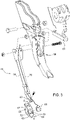
FIG. 1 is a perspective view showing a planter row unit with a furrow shaper (in phantom); -
FIG. 2 is a side elevational view, with portions broken away, showing the planter row unit; -
FIG. 3 is an exploded perspective showing the furrow shaper, a guard of a frame of the row unit to which the furrow shaper is to be mounted, and a shank of the frame to which the guard is to be mounted; -
FIG. 4 is a perspective view showing the furrow shaper mounted to the guard; -
FIG. 5 is a side elevational view showing the guard with a groove (dashed) positioned to receive wiring routed along a leg of the furrow shaper upon deflection of the leg; -
FIG. 6 is an enlarged sectional view, taken along lines 6-6 ofFIG. 3 , of a foot of the furrow shaper, a sensor enclosed in a cavity of the foot; -
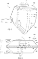
FIG. 7 is a perspective view showing a second embodiment of the foot and sensor; -
FIG. 8 is a bottom view showing the foot and sensor ofFIG. 7 ; and -
FIG. 9 is a sectional view taken along lines 9-9 ofFIG. 7 . - Referring to
FIGS. 1 and2 , aplanter row unit 10 may be used in a planter having a number of such row units mounted to a toolbar of the planter. Eachrow unit 10 is configured to plant seeds in the ground, as the planter is moved in a planting direction oftravel 12 through a field by, for example, a tractor. - The
row unit 10 comprises aframe 14 and a four-bar linkage 16 that mounts theframe 14 to the toolbar. Thelinkage 16 comprises abracket 18 bolted to the toolbar. - The
row unit 10 comprises afurrow opener 20 mounted to theframe 14 to open a furrow in the ground. Thefurrow opener 20 may comprise two discs 24, one of which is shown, for example, inFIG. 2 , positioned relative to one another to open the furrow. - The
row unit 10 comprises a furrow closer 26 mounted to theframe 14 to close the furrow. The furrow closer 26 is positioned rearwardly of thefurrow opener 20 relative to the planting direction oftravel 12 of therow unit 10. The furrow closer 26 may comprise twoclosing wheels 28 positioned relative to one another to close the furrow. - The
row unit 10 comprises twogauge wheels 30 mounted to and positioned on opposite sides of theframe 14. Thegauge wheels 30 cooperate to establish the depth of thefurrow opener 20 and correspondingly the depth of the furrow. Thegauge wheels 30 are vertically movable relative to theframe 14 to a stop which sets the furrow depth. - The
row unit 10 comprises aseed delivery mechanism 32 mounted to theframe 14 to deposit seed into the furrow. Theseed delivery mechanism 32 is positioned between thefurrow opener 20 and the furrow closer 26 relative to a planting direction oftravel 12 of therow unit 10 - The
seed delivery mechanism 32 is included in aseed supply system 36 of therow unit 10. Illustratively, theseed supply system 36 comprises ahopper 38 and avacuum seed meter 40. Thehopper 38 is configured to receive seed from a source (not shown) via ahopper inlet 42. Theseed meter 40 is configured to receive seed from thehopper 38, and singulate the seed on respective apertures (not shown) of themeter 40 to which a vacuum pressure is applied. - Illustratively, the
seed delivery mechanism 32 is configured as a brush-belt cartridge. The brush-belt cartridge comprises a brush belt 44 (shown diagrammatically) circulating to pick up seed one-by-one from theseed meter 40 and to deliver the seed to aseed outlet 46 of themechanism 32 where the brush belt 44 releases the seed, which is under centrifugal force as the brush belt 44 makes a turn near the bottom of its cycle. Themechanism 32 is configured to deposit each seed into the furrow. Other seed delivery mechanisms may be used to deposit seed into the furrow, such as, for example, a seed tube. - The
row unit 10 comprises afurrow shaper 48 mounted to theframe 14. Thefurrow shaper 48 is positioned relative to thefurrow opener 20 and theseed delivery mechanism 32 to shape the furrow, opened by thefurrow opener 20, ahead of seed deposited into the furrow by theseed delivery mechanism 32 relative to the planting direction oftravel 12 of theplanter row unit 10. Illustratively, thefurrow shaper 48 is positioned at least in part between thefurrow opener 20 and theseed delivery mechanism 32 relative to the planting direction oftravel 12. - When the
furrow opener 20 opens the furrow, it may form the furrow with a W-shaped cross-section lateral to the planting direction oftravel 12, in which case the seed may fall to one side or the other of the furrow in a somewhat uncontrolled manner. Thefurrow shaper 48 is configured to shape the bottom of the furrow such that the bottom of the furrow has a generally V-shaped lateral cross-section, so as to position the seed in the vertex of the V shape. Alternatively, thefurrow shaper 48 may be configured to shape the bottom of the furrow so as to have a U-shaped lateral cross-section, or other suitable shape. - Referring to
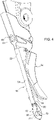
FIGS. 3-5 , thefurrow shaper 48 comprises aproximal end 50 and adistal end 52. Theproximal end 50 is mounted to theframe 14. Thedistal end 52 is configured to form the furrow, for example, with the V shape. - The
furrow shaper 48 comprises aleg 54 and afoot 56 profiled to shape the furrow. Theleg 54 provides theproximal end 50 of thefurrow shaper 48, which is also the proximal end of theleg 54. Theproximal end 50 comprises a pair of flanges, the flanges being positioned on either side of aguard 58 of theframe 14. The flanges are fixed to the guard 58 (e.g., bolted with a bolt, a nut, a washer positioned on one side of theguard 58, and another washer positioned on the opposite side of the guard 58). Theleg 54 projects downwardly to position thefoot 56 in the furrow. - The
foot 56 provides thedistal end 52 of thefurrow shaper 48, and is mounted to adistal end 60 of the leg 54 (e.g., with a screw). Thefoot 56 is configured to shape the furrow, for example, with the V shape. - The
guard 58 is positioned between thefurrow shaper 48 and theseed delivery mechanism 32 to shield theseed delivery mechanism 32 from dirt and debris during planting. Theguard 58 is a wearable item (made, for example, of metal). It is fixed (e.g., bolted) to a shank 62 of theframe 14 so as to be removable therefrom and replaced upon reaching the end of its service life, in which case thefurrow shaper 48 may be removed from the worn guard and mounted to a fresh guard. The bottom of the shank 62 comprises apost 61 received in apost-receiving portion 63 of theguard 58. - The
furrow shaper 48 is spring biased downwardly to press against the bottom of the furrow. As such, thefurrow shaper 48 is able to maintain contact with the bottom of the furrow despite some variation in the level of the ground or bottom of the furrow. - The
leg 50 is spring biased downwardly to press thefoot 56 against the bottom of the furrow. Theleg 50 may be a flat spring to provide this spring bias. - The
row unit 10 comprises asensor 64 mounted to thefurrow shaper 48 and configured to detect a parameter related to seed planting. Thesensor 64 may be, for example, a soil sensor. In an embodiment, the parameter is soil moisture, and, in another embodiment, the parameter is soil temperature. In other embodiments, the parameter may be soil type (e.g., clay content) or nutrient content (e.g., nitrogen content) indicative of soil fertility. Thesensor 64 may be a capacitive sensor (e.g., for sensing soil capacitance as an indication of soil moisture), a near-infrared sensor, a thermal-imaging sensor, or an optical sensor, to name but a few sensor types. In yet other embodiments, the parameter may be organic matter content or residue presence, in which case thesensor 64 may be an optical sensor (i.e., an electromagnetic spectrum analyzer). - Referring to
FIGS. 3 ,5 , and6 , the sensor 64 (shown diagrammatically) is mounted to thefoot 56. Illustratively, thesensor 64 is embedded in thefoot 56. Thefoot 56 comprises acavity 66 included in abody 67 of thefoot 56 and in which thesensor 64 is enclosed by thefoot 56. Thefoot 56 comprises alid 68 closing thecavity 56 so as to enclose thesensor 64 within thecavity 56. Thelid 68 is coupled to thebody 67, for example, by an adhesive seal around the edge of thelid 68, by fastening thelid 68 to the body 67 (e.g., bolted), or other suitable approach. Thelid 68 may be made of a plastic material or other suitable material. Thefoot 56 comprises a potting material or other permanent molding material generally filling thecavity 66 and holding thesensor 64 in place within thecavity 56. - The
sensor 64 comprises aprocessing unit 70 and a number ofelectrodes 72 electrically coupled to theprocessing unit 70. Theprocessing unit 70 may be mounted to a circuit board positioned in thecavity 66. Eachelectrode 72 may be coupled electrically to theprocessing unit 70 by a wired connection, a pin, a wireless connection, or other suitable electrical connection. Illustratively, there are twoelectrodes 72. It is to be understood that the number of electrodes may be more or less than two. - The
processing unit 70 and theelectrodes 72 are enclosed within thecavity 66 by thefoot 56 upon closure of thecavity 66 by thelid 68. Theprocessing unit 70 and theelectrodes 72 are embedded in the potting material or other permanent molding material so as to be held in place in thecavity 66. - The
sensor 64 is electrically coupled to acontroller 74 of the row unit 10 (FIG. 2 ). Thesensor 64 is configured to detect the parameter related to seed planting and to output a signal corresponding to the parameter ("sensor parameter signal") to thecontroller 74, which may be configured, for example, as a microcontroller or other suitable controller. Theprocessing unit 70 is configured to provide electrical power for operation of theelectrodes 72. Theelectrodes 72 are configured to detect the parameter related to seed planting. Theelectrodes 72 are configured to do so through the material of thebody 67 of thefoot 56. Each of theelectrodes 72 is configured to generate a signal corresponding to the parameter ("electrode parameter signal"). Theprocessing unit 70 is configured to receive the electrode parameter signals from theelectrodes 72, provide signal conditioning, and output the sensor parameter signal, dependent on the electrode parameter signals, to thecontroller 74. - The
body 67 is made, for example, of a wear-resistant and non-conductive material. It is wear-resistant due to its contact with the ground, and non-conductive to facilitate transmission and reception of signals from and to theelectrodes 72 through thebody 67. Thebody 67 may be made, for example, of a ceramic material (e.g., a hard ceramic with high wear resistance like Magnesia Stabilized Zirconia material (MSZ)). In other embodiments, thebody 67 may be made of ultra-high molecular weight polyethylene (UHMW), or other suitable plastic material. - The
controller 74 is mounted to and within theframe 14. Theprocessing unit 70 and thecontroller 74 are electrically coupled to one another viawiring 76 of the row unit 10 (shown diagrammatically). - The
wiring 76 exits thefoot 56 through a wiring exit. A sealed connection is established between thewiring 76 and the wiring exit, to block ingress of debris. In the illustrated embodiment, thelid 68 comprises the wiring exit, such that thewiring 76 exits thefoot 56 through the wiring exit of thelid 68. In other embodiments, the wiring exit for thewiring 76 may be formed in thebody 67. - The
wiring 76 may be configured in a wide variety of ways. For example, thewiring 76 may comprise arigid portion 77 and a flexible portion 78 (both shown diagrammatically). Therigid portion 77 may comprise a number of rigid conductive pins extending from theprocessing unit 70 through the wiring exit of thelid 68, with the sealed connection established between the pins and the wiring exit. The pins may make a turn upon exit from the lid so as to be L-shaped. Theflexible portion 78 may comprises a number of flexible wires attached to the pins. In another example, therigid portion 77 may be replaced by an extendedflexible portion 77. - The
wiring 76 is routed along theleg 54 where thewiring 76 is held in place with a number of wiring retainers coupled to the leg 54 (e.g., two clips clipped onto the leg 54). Theguard 58 comprises agroove 80 aligned with theleg 54 to receive thewiring 76 in response to deflection of the leg 54 (e.g., if theleg 54 is deflected upwardly and rearwardly by the ground). Thegroove 80 may thus help protect thewiring 76 upon deflection of theleg 54. Theguard 58 comprises a through-hole 82 through which thewiring 76 passes to a point rearward of theguard 58. Thewiring 76 passes along the shank 62 into a cavity within theframe 14 to thecontroller 74. In other embodiments, theprocessing unit 70 and thecontroller 74 may be electrically coupled via a wireless connection. - Referring to
FIGS. 7-9 , according to another embodiment, afoot 156 and a sensor 164 (shown diagrammatically) may be used in place of thefoot 56 and thesensor 64. As such, although the reference numbers are different in the description of this embodiment, thefoot 156 and thesensor 164 are similar in construction and function to thefoot 56 and thesensor 64, except as noted herein. - The
sensor 164 comprises aprocessing unit 170 and a number ofelectrodes 172 electrically coupled to theprocessing unit 170. Theprocessing unit 70 may be mounted to a circuit board positioned in thecavity 166. Theprocessing unit 170 is positioned and enclosed within thecavity 166 by thefoot 156 upon closure of thecavity 66 by thelid 168. Theprocessing unit 170 is embedded in the potting material or other permanent molding material so as to be held in place in thecavity 166. - Illustratively, there are four
electrodes 172, but it is to be understood that the number ofelectrodes 172 may be more or less than four. Theelectrodes 172 are arranged in a first set of twoelectrodes 172 positioned on afirst side 186 of acenterline 188 of thefoot 156, and a second set of twoelectrodes 172 positioned on an oppositesecond side 190 of thecenterline 188. Thecenterline 188 is positioned at a vertex of the V shape of thefoot 156 and is parallel to the planting direction oftravel 12. The first and second sets ofelectrodes 172 are staggered from one another along the centerline 188 (in other embodiments, they may be even with one another along the centerline 188). - The
electrodes 172 are embedded in thefoot 156 and positioned outside thecavity 166. Theelectrodes 172 are integrated into anexterior 184 of thebody 167 of thefoot 156 for exposure to and contact with soil. The exterior 184 comprises a respective recess for eachelectrode 172 in which theelectrode 172 is positioned and affixed or otherwise mounted (e.g., mechanically retained; adhesive; potting material or other permanent molding material), for protection of theelectrode 172 as theelectrode 172 is moved through the soil. Theelectrodes 172 may thus be characterized as external electrodes, while theelectrodes 72 may be characterized as internal electrodes. - The
body 167 is made, for example, of a wear-resistant material. Since theelectrodes 172 are external electrodes, thebody 167 need not be made of a non-conductive material (although it can be). Thebody 67 may be made, for example, of a ceramic material (e.g., a hard ceramic with high wear resistance like Magnesia Stabilized Zirconia material (MSZ)). In other embodiments, thebody 67 may be made of ultra-high molecular weight polyethylene (UHMW), or other suitable plastic material. - The
electrodes 172 are electrically coupled to theprocessing unit 170. Eachelectrode 172 may be electrically coupled to theprocessing unit 170 by a wired connection, a pin, a wireless connection, or other suitable electrical connection. Illustratively, eachelectrode 172 is electrically coupled to theprocessing unit 170 by apin 173 extending from theelectrode 172 to theprocessing unit 170 through a respectiveinternal conduit 174 formed in thebody 167 of thefoot 156 and in communication with thecavity 166.
While the present disclosure has been illustrated and described in detail in the drawings and foregoing description, such illustration and description is to be considered as disclosing examples and not restrictive in character. It is to be understood that illustrative embodiments have been shown.
Claims (10)
- A planter row unit (10), comprising:a frame (14);a furrow opener (20) mounted to the frame (14) to open a furrow;a seed delivery mechanism (32) mounted to the frame (14) to deposit seed into the furrow;a furrow shaper (48) mounted to the frame (14) and positioned relative to the furrow opener (20) and the seed delivery mechanism to shape the furrow, opened by the furrow opener (20), ahead of seed de-posited into the furrow by the seed delivery mechanism relative to a planting direction of travel of the planter row unit (10); anda sensor (64) mounted to the furrow shaper (48) and configured to detect a parameter related to seed planting;wherein the furrow shaper (48) comprises a foot (56) profiled to shape the furrow, and the sensor (64) is mounted to the foot (56); and wherein the foot (56) comprises a cavity (66), and the sensor (64) is enclosed within the cavity (66) by the foot (56),wherein the foot (56) comprises a lid (68) closing the cavity (66),wherein the furrow shaper (48) comprises a leg (54) projecting downwardly, and the foot (56) is mounted to an end of the leg (54) andwiring (76) routed along the leg (54), wherein the frame (14) comprises a guard (58) positioned between the furrow shaper (48) and the seed delivery mechanism, and the guard comprises a groove aligned with the leg (54) to receive the wiring in response to deflection of the leg (54).
- The planter row unit of claim 1, wherein the sensor is embedded in the foot.
- The planter row unit of claim 1, wherein the sensor comprises an electrode (72), and the electrode is enclosed within the cavity by the foot.
- The planter row unit of claim 1, wherein the sensor comprises a processing unit (70) enclosed within the cavity by the foot.
- The planter row unit of claim 1, wherein the leg (54) is spring biased downwardly to press the foot against the bottom of the furrow.
- The planter row unit of claim 1, wherein the leg is a flat spring.
- The planter row unit of any preceding claim, wherein the furrow shaper is spring biased downwardly to press against the bottom of the furrow.
- The planter row unit of any preceding claim, wherein the sensor is a soil sensor.
- The planter row unit of any preceding claim, wherein the parameter is soil moisture.
- The planter row unit of any preceding claim, wherein the parameter is soil temperature.
Applications Claiming Priority (1)
| Application Number | Priority Date | Filing Date | Title |
|---|---|---|---|
| US15/432,435 US10257973B2 (en) | 2017-02-14 | 2017-02-14 | Row planter unit with sensor-mounted furrow shaper |
Publications (3)
| Publication Number | Publication Date |
|---|---|
| EP3360402A1 EP3360402A1 (en) | 2018-08-15 |
| EP3360402B1 EP3360402B1 (en) | 2020-01-01 |
| EP3360402B2 true EP3360402B2 (en) | 2022-11-16 |
Family
ID=60954911
Family Applications (1)
| Application Number | Title | Priority Date | Filing Date |
|---|---|---|---|
| EP18151092.6A Active EP3360402B2 (en) | 2017-02-14 | 2018-01-10 | Row planter unit with sensor-mounted furrow shaper |
Country Status (3)
| Country | Link |
|---|---|
| US (1) | US10257973B2 (en) |
| EP (1) | EP3360402B2 (en) |
| AR (1) | AR111506A1 (en) |
Families Citing this family (25)
| Publication number | Priority date | Publication date | Assignee | Title |
|---|---|---|---|---|
| US8850995B2 (en) | 2009-02-02 | 2014-10-07 | Deere & Company | Seeding machine with seed delivery system |
| US8671856B2 (en) | 2009-02-02 | 2014-03-18 | Deere & Company | Planting unit for a seeding machine having blocking member to control hand-off of seed from a seed meter to a seed delivery system |
| US8850998B2 (en) | 2011-03-25 | 2014-10-07 | Deere & Company | Planting unit for a seeding machine having a seed meter and seed delivery system |
| US10327374B2 (en) | 2011-04-27 | 2019-06-25 | Kinze Manufacturing, Inc. | Remote adjustment of a row unit of an agricultural device |
| AR113306A1 (en) | 2017-10-03 | 2020-04-08 | Ag Leader Tech | CONTROLLED AIR IMPULSE DOSING APPARATUS FOR AN AGRICULTURAL SEED DRILL AND RELATED SYSTEMS AND METHODS |
| US11277961B2 (en) | 2018-02-09 | 2022-03-22 | Ag Leader Technology | Seed spacing device for an agricultural planter and related systems and methods |
| US10813281B2 (en) | 2018-02-20 | 2020-10-27 | Ag Leader Technology | Apparatus, systems and methods for applying fluid |
| US20190297769A1 (en) | 2018-03-30 | 2019-10-03 | Ag Leader Technology | Devices, Systems, and Methods for Seed Trench Protection |
| US11064649B2 (en) | 2018-06-27 | 2021-07-20 | Deere & Company | Seeding system |
| US11058047B2 (en) | 2018-06-27 | 2021-07-13 | Deere & Company | Seeding system |
| US11051445B2 (en) | 2018-06-27 | 2021-07-06 | Deere & Company | Seeding system |
| EP3840561B1 (en) | 2018-08-24 | 2023-06-07 | Precision Planting LLC | Agricultural trench depth sensing system and method |
| US12520744B2 (en) | 2018-11-15 | 2026-01-13 | Ag Leader Technology | On the go organic matter sensor and associated systems and methods |
| US11523554B2 (en) | 2019-01-25 | 2022-12-13 | Ag Leader Technology | Dual seed meter and related systems and methods |
| US11369054B2 (en) | 2019-06-26 | 2022-06-28 | Cnh Industrial Canada, Ltd. | Smart sensor system for seeding implement |
| US11785881B2 (en) | 2019-08-19 | 2023-10-17 | Ag Leader Technology | Adjustable seed meter and related systems and methods |
| US12268115B2 (en) | 2020-02-07 | 2025-04-08 | Ag Leader Technology | Planter obstruction monitoring and associated devices and methods |
| US12564121B2 (en) * | 2020-07-01 | 2026-03-03 | Deere & Company | Implement mounted sensors sensing surface/furrow characteristics and control |
| US12550808B2 (en) * | 2020-09-30 | 2026-02-17 | Plantium S.A. | Device for shaping a furrow profile, sensing soil properties and dosing fluids |
| US12477973B2 (en) | 2020-11-13 | 2025-11-25 | Ag Leader Technology | Agricultural high speed row unit |
| EP4351308A1 (en) | 2021-07-21 | 2024-04-17 | Kinze Manufacturing, Inc. | A row unit component for agricultural implements |
| DE102021123828A1 (en) | 2021-09-15 | 2023-03-16 | Amazonen-Werke H. Dreyer SE & Co. KG | Catch roller for a spreading unit of an agricultural spreading machine |
| US20230180653A1 (en) * | 2021-12-14 | 2023-06-15 | Ag Leader Technology | Seed tube guard and associated systems and methods of use |
| US20230413720A1 (en) * | 2021-12-14 | 2023-12-28 | Ag Leader Technology | Seed tube guard and associated systems and methods of use |
| WO2024151364A1 (en) * | 2023-01-11 | 2024-07-18 | Deere & Company | Structured-light-based trench profile measurement for planter row unit |
Citations (2)
| Publication number | Priority date | Publication date | Assignee | Title |
|---|---|---|---|---|
| WO2014153157A1 (en) † | 2013-03-14 | 2014-09-25 | Precision Planting Llc | Systems, methods, and apparatus for agricultural implement trench depth control and soil monitoring |
| WO2016205422A1 (en) † | 2015-06-15 | 2016-12-22 | Precision Planting Llc | Agricultural operation monitoring apparatus, systems and methods |
Family Cites Families (21)
| Publication number | Priority date | Publication date | Assignee | Title |
|---|---|---|---|---|
| US2142454A (en) | 1937-10-05 | 1939-01-03 | Frank C Kirkpatrick | Spring latch for cultivators |
| US3380411A (en) | 1965-10-22 | 1968-04-30 | Int Harvester Co | Balk remover for planters |
| US4598654A (en) | 1981-12-31 | 1986-07-08 | Acra-Plant, Inc. | Furrow opener and follower blade |
| US20020131046A1 (en) | 2001-03-13 | 2002-09-19 | Kejr, Inc. | Optical soil sensor for mobilized measurement of in-situ soil characteristics |
| FR2956004B1 (en) | 2010-02-11 | 2012-03-16 | Ribouleau Monosem | SEMEUR ASSEMBLY COMPRISING A POINT-MOUNTED ORGAN BETWEEN TWO SILLON OPENING DISKS, AND MEANS FOR RELEASING SAID ORGAN WITHOUT DISC DISASSEMBLY |
| CA3095400C (en) | 2011-09-27 | 2022-07-19 | Precision Planting Llc | Seed delivery apparatus, systems, and methods |
| JP5750092B2 (en) | 2012-12-05 | 2015-07-15 | 太陽誘電株式会社 | Capacitor |
| CA3109010C (en) | 2013-08-30 | 2022-07-05 | Precision Planting Llc | Seed delivery apparatus, systems, and methods |
| CA3214274A1 (en) | 2014-05-08 | 2015-11-12 | Precision Planting Llc | Systems, methods, and apparatus for agricultural liquid application |
| US10785905B2 (en) | 2014-05-08 | 2020-09-29 | Precision Planting Llc | Liquid application apparatus comprising a seed firmer |
| AU2015346218B2 (en) | 2014-11-12 | 2019-09-05 | Precision Planting Llc | Seed planting apparatus, systems and methods |
| CA3155706C (en) | 2015-06-15 | 2024-03-26 | Precision Planting Llc | Systems, methods, and apparatus for agricultural liquid application |
| US10221591B2 (en) * | 2015-07-07 | 2019-03-05 | The Sun Lock Company, Ltd. | Padlock with fully integrated dual locking mechanism with reset mechanism |
| RU2720278C2 (en) | 2015-09-18 | 2020-04-28 | ПРЕСИЖН ПЛЭНТИНГ ЭлЭлСи | Device, system and method of soil criteria monitoring during soil cultivation operations and control of tillage working tools |
| US10375879B2 (en) | 2015-10-02 | 2019-08-13 | Deere & Company | Soil characteristic sensors on ground-engaging elements of a planting machine |
| WO2017112892A1 (en) | 2015-12-23 | 2017-06-29 | Precision Planting Llc | Agricultural input placement systems, methods, and apparatus |
| MX2018013898A (en) | 2016-05-13 | 2019-06-24 | Prec Planting Llc | CLOSING SENSORS OF A PLANTING GROOVE |
| WO2018013860A2 (en) | 2016-07-14 | 2018-01-18 | Precision Planting Llc | Systems, implements, and methods for passive seed orientation within agricultural fields |
| CN109688792B (en) | 2016-07-14 | 2023-02-14 | 精密种植有限责任公司 | System, tool and method for seed orientation in an agricultural field using a seed locator |
| CA3031105C (en) | 2016-07-22 | 2024-05-28 | Precision Planting Llc | Agricultural trench depth sensing systems, methods, and apparatus |
| CN107360762B (en) | 2017-09-05 | 2019-05-17 | 吴瀛洲 | Annular ring type Precision Seeding feed mechanism for seed |
-
2017
- 2017-02-14 US US15/432,435 patent/US10257973B2/en active Active
-
2018
- 2018-01-10 EP EP18151092.6A patent/EP3360402B2/en active Active
- 2018-01-12 AR ARP180100077A patent/AR111506A1/en active IP Right Grant
Patent Citations (2)
| Publication number | Priority date | Publication date | Assignee | Title |
|---|---|---|---|---|
| WO2014153157A1 (en) † | 2013-03-14 | 2014-09-25 | Precision Planting Llc | Systems, methods, and apparatus for agricultural implement trench depth control and soil monitoring |
| WO2016205422A1 (en) † | 2015-06-15 | 2016-12-22 | Precision Planting Llc | Agricultural operation monitoring apparatus, systems and methods |
Also Published As
| Publication number | Publication date |
|---|---|
| EP3360402B1 (en) | 2020-01-01 |
| AR111506A1 (en) | 2019-07-24 |
| US10257973B2 (en) | 2019-04-16 |
| US20180228078A1 (en) | 2018-08-16 |
| BR102018000670A2 (en) | 2018-10-30 |
| EP3360402A1 (en) | 2018-08-15 |
Similar Documents
| Publication | Publication Date | Title |
|---|---|---|
| EP3360402B2 (en) | Row planter unit with sensor-mounted furrow shaper | |
| US8631749B2 (en) | Seed tube egress-mounted seed sensor | |
| US10798872B1 (en) | Agricultural planter with automatic depth and seeding rate control | |
| US11067560B2 (en) | System for measuring multiple soil properties using narrow profile sensor configuration | |
| US10045477B2 (en) | Seed firming assembly for agricultural seeders and mounting system therefor | |
| US5533458A (en) | Seed tube for an agricultural seeding machine | |
| US20230413720A1 (en) | Seed tube guard and associated systems and methods of use | |
| CA3189260A1 (en) | Seed trench closing sensors | |
| HUP0001869A2 (en) | Two piece seed boot for a seeding machine | |
| US10729052B1 (en) | System and method for measuring soil conductivity using existing farm implements | |
| US10980164B2 (en) | Wear determination for agricultural implement | |
| US4257340A (en) | Tractor-drawn seeding apparatus | |
| US20020189513A1 (en) | Furrow opener for dual shank seeders | |
| BR102018000670B1 (en) | ROW PLANTER UNIT | |
| US6192812B1 (en) | Debris shield for a planter unit | |
| US20240040952A1 (en) | Agricultural implement with sensors for measuring soil properties | |
| JP2585201B2 (en) | Alarm device for fertilizer and seeder | |
| BR102022009904A2 (en) | ELECTRICAL HARNESS ASSEMBLIES FOR AN AGRICULTURAL IMPLEMENT AND FORMATION METHOD | |
| BR112013017260B1 (en) | Seed sensor, method for detecting seeds, and electromagnetic energy sensor for detecting the passage of seeds. | |
| CA3249150A1 (en) | Row unit for a sowing machine and sowing machine having row units | |
| JP2608859B2 (en) | Fertilizer, seeder | |
| JPH0534499Y2 (en) | ||
| RU160725U1 (en) | SINGLE DISC ANCHOR | |
| CN111345142A (en) | Ditching device | |
| JP2608859C (en) |
Legal Events
| Date | Code | Title | Description |
|---|---|---|---|
| PUAI | Public reference made under article 153(3) epc to a published international application that has entered the european phase |
Free format text: ORIGINAL CODE: 0009012 |
|
| STAA | Information on the status of an ep patent application or granted ep patent |
Free format text: STATUS: THE APPLICATION HAS BEEN PUBLISHED |
|
| AK | Designated contracting states |
Kind code of ref document: A1 Designated state(s): AL AT BE BG CH CY CZ DE DK EE ES FI FR GB GR HR HU IE IS IT LI LT LU LV MC MK MT NL NO PL PT RO RS SE SI SK SM TR |
|
| AX | Request for extension of the european patent |
Extension state: BA ME |
|
| STAA | Information on the status of an ep patent application or granted ep patent |
Free format text: STATUS: REQUEST FOR EXAMINATION WAS MADE |
|
| 17P | Request for examination filed |
Effective date: 20190215 |
|
| RBV | Designated contracting states (corrected) |
Designated state(s): AL AT BE BG CH CY CZ DE DK EE ES FI FR GB GR HR HU IE IS IT LI LT LU LV MC MK MT NL NO PL PT RO RS SE SI SK SM TR |
|
| GRAP | Despatch of communication of intention to grant a patent |
Free format text: ORIGINAL CODE: EPIDOSNIGR1 |
|
| STAA | Information on the status of an ep patent application or granted ep patent |
Free format text: STATUS: GRANT OF PATENT IS INTENDED |
|
| INTG | Intention to grant announced |
Effective date: 20190916 |
|
| GRAS | Grant fee paid |
Free format text: ORIGINAL CODE: EPIDOSNIGR3 |
|
| GRAA | (expected) grant |
Free format text: ORIGINAL CODE: 0009210 |
|
| STAA | Information on the status of an ep patent application or granted ep patent |
Free format text: STATUS: THE PATENT HAS BEEN GRANTED |
|
| AK | Designated contracting states |
Kind code of ref document: B1 Designated state(s): AL AT BE BG CH CY CZ DE DK EE ES FI FR GB GR HR HU IE IS IT LI LT LU LV MC MK MT NL NO PL PT RO RS SE SI SK SM TR |
|
| REG | Reference to a national code |
Ref country code: GB Ref legal event code: FG4D |
|
| REG | Reference to a national code |
Ref country code: CH Ref legal event code: EP Ref country code: AT Ref legal event code: REF Ref document number: 1218610 Country of ref document: AT Kind code of ref document: T Effective date: 20200115 |
|
| REG | Reference to a national code |
Ref country code: IE Ref legal event code: FG4D |
|
| REG | Reference to a national code |
Ref country code: DE Ref legal event code: R096 Ref document number: 602018001799 Country of ref document: DE |
|
| REG | Reference to a national code |
Ref country code: NL Ref legal event code: MP Effective date: 20200101 |
|
| REG | Reference to a national code |
Ref country code: LT Ref legal event code: MG4D |
|
| PG25 | Lapsed in a contracting state [announced via postgrant information from national office to epo] |
Ref country code: NL Free format text: LAPSE BECAUSE OF FAILURE TO SUBMIT A TRANSLATION OF THE DESCRIPTION OR TO PAY THE FEE WITHIN THE PRESCRIBED TIME-LIMIT Effective date: 20200101 Ref country code: RS Free format text: LAPSE BECAUSE OF FAILURE TO SUBMIT A TRANSLATION OF THE DESCRIPTION OR TO PAY THE FEE WITHIN THE PRESCRIBED TIME-LIMIT Effective date: 20200101 Ref country code: LT Free format text: LAPSE BECAUSE OF FAILURE TO SUBMIT A TRANSLATION OF THE DESCRIPTION OR TO PAY THE FEE WITHIN THE PRESCRIBED TIME-LIMIT Effective date: 20200101 Ref country code: FI Free format text: LAPSE BECAUSE OF FAILURE TO SUBMIT A TRANSLATION OF THE DESCRIPTION OR TO PAY THE FEE WITHIN THE PRESCRIBED TIME-LIMIT Effective date: 20200101 Ref country code: CZ Free format text: LAPSE BECAUSE OF FAILURE TO SUBMIT A TRANSLATION OF THE DESCRIPTION OR TO PAY THE FEE WITHIN THE PRESCRIBED TIME-LIMIT Effective date: 20200101 Ref country code: PT Free format text: LAPSE BECAUSE OF FAILURE TO SUBMIT A TRANSLATION OF THE DESCRIPTION OR TO PAY THE FEE WITHIN THE PRESCRIBED TIME-LIMIT Effective date: 20200527 Ref country code: NO Free format text: LAPSE BECAUSE OF FAILURE TO SUBMIT A TRANSLATION OF THE DESCRIPTION OR TO PAY THE FEE WITHIN THE PRESCRIBED TIME-LIMIT Effective date: 20200401 |
|
| PG25 | Lapsed in a contracting state [announced via postgrant information from national office to epo] |
Ref country code: SE Free format text: LAPSE BECAUSE OF FAILURE TO SUBMIT A TRANSLATION OF THE DESCRIPTION OR TO PAY THE FEE WITHIN THE PRESCRIBED TIME-LIMIT Effective date: 20200101 Ref country code: LV Free format text: LAPSE BECAUSE OF FAILURE TO SUBMIT A TRANSLATION OF THE DESCRIPTION OR TO PAY THE FEE WITHIN THE PRESCRIBED TIME-LIMIT Effective date: 20200101 Ref country code: BG Free format text: LAPSE BECAUSE OF FAILURE TO SUBMIT A TRANSLATION OF THE DESCRIPTION OR TO PAY THE FEE WITHIN THE PRESCRIBED TIME-LIMIT Effective date: 20200401 Ref country code: IS Free format text: LAPSE BECAUSE OF FAILURE TO SUBMIT A TRANSLATION OF THE DESCRIPTION OR TO PAY THE FEE WITHIN THE PRESCRIBED TIME-LIMIT Effective date: 20200501 Ref country code: GR Free format text: LAPSE BECAUSE OF FAILURE TO SUBMIT A TRANSLATION OF THE DESCRIPTION OR TO PAY THE FEE WITHIN THE PRESCRIBED TIME-LIMIT Effective date: 20200402 Ref country code: HR Free format text: LAPSE BECAUSE OF FAILURE TO SUBMIT A TRANSLATION OF THE DESCRIPTION OR TO PAY THE FEE WITHIN THE PRESCRIBED TIME-LIMIT Effective date: 20200101 |
|
| REG | Reference to a national code |
Ref country code: DE Ref legal event code: R026 Ref document number: 602018001799 Country of ref document: DE |
|
| PLBI | Opposition filed |
Free format text: ORIGINAL CODE: 0009260 |
|
| REG | Reference to a national code |
Ref country code: BE Ref legal event code: MM Effective date: 20200131 |
|
| PLAX | Notice of opposition and request to file observation + time limit sent |
Free format text: ORIGINAL CODE: EPIDOSNOBS2 |
|
| PG25 | Lapsed in a contracting state [announced via postgrant information from national office to epo] |
Ref country code: SK Free format text: LAPSE BECAUSE OF FAILURE TO SUBMIT A TRANSLATION OF THE DESCRIPTION OR TO PAY THE FEE WITHIN THE PRESCRIBED TIME-LIMIT Effective date: 20200101 Ref country code: LU Free format text: LAPSE BECAUSE OF NON-PAYMENT OF DUE FEES Effective date: 20200110 Ref country code: EE Free format text: LAPSE BECAUSE OF FAILURE TO SUBMIT A TRANSLATION OF THE DESCRIPTION OR TO PAY THE FEE WITHIN THE PRESCRIBED TIME-LIMIT Effective date: 20200101 Ref country code: SM Free format text: LAPSE BECAUSE OF FAILURE TO SUBMIT A TRANSLATION OF THE DESCRIPTION OR TO PAY THE FEE WITHIN THE PRESCRIBED TIME-LIMIT Effective date: 20200101 Ref country code: DK Free format text: LAPSE BECAUSE OF FAILURE TO SUBMIT A TRANSLATION OF THE DESCRIPTION OR TO PAY THE FEE WITHIN THE PRESCRIBED TIME-LIMIT Effective date: 20200101 Ref country code: ES Free format text: LAPSE BECAUSE OF FAILURE TO SUBMIT A TRANSLATION OF THE DESCRIPTION OR TO PAY THE FEE WITHIN THE PRESCRIBED TIME-LIMIT Effective date: 20200101 Ref country code: MC Free format text: LAPSE BECAUSE OF FAILURE TO SUBMIT A TRANSLATION OF THE DESCRIPTION OR TO PAY THE FEE WITHIN THE PRESCRIBED TIME-LIMIT Effective date: 20200101 Ref country code: RO Free format text: LAPSE BECAUSE OF FAILURE TO SUBMIT A TRANSLATION OF THE DESCRIPTION OR TO PAY THE FEE WITHIN THE PRESCRIBED TIME-LIMIT Effective date: 20200101 |
|
| 26 | Opposition filed |
Opponent name: AMAZONEN-WERKE H. DREYER GMBH & CO. KG Effective date: 20200930 |
|
| REG | Reference to a national code |
Ref country code: AT Ref legal event code: MK05 Ref document number: 1218610 Country of ref document: AT Kind code of ref document: T Effective date: 20200101 |
|
| PG25 | Lapsed in a contracting state [announced via postgrant information from national office to epo] |
Ref country code: BE Free format text: LAPSE BECAUSE OF NON-PAYMENT OF DUE FEES Effective date: 20200131 |
|
| PG25 | Lapsed in a contracting state [announced via postgrant information from national office to epo] |
Ref country code: IT Free format text: LAPSE BECAUSE OF FAILURE TO SUBMIT A TRANSLATION OF THE DESCRIPTION OR TO PAY THE FEE WITHIN THE PRESCRIBED TIME-LIMIT Effective date: 20200101 Ref country code: AT Free format text: LAPSE BECAUSE OF FAILURE TO SUBMIT A TRANSLATION OF THE DESCRIPTION OR TO PAY THE FEE WITHIN THE PRESCRIBED TIME-LIMIT Effective date: 20200101 Ref country code: IE Free format text: LAPSE BECAUSE OF NON-PAYMENT OF DUE FEES Effective date: 20200110 |
|
| PG25 | Lapsed in a contracting state [announced via postgrant information from national office to epo] |
Ref country code: SI Free format text: LAPSE BECAUSE OF FAILURE TO SUBMIT A TRANSLATION OF THE DESCRIPTION OR TO PAY THE FEE WITHIN THE PRESCRIBED TIME-LIMIT Effective date: 20200101 Ref country code: PL Free format text: LAPSE BECAUSE OF FAILURE TO SUBMIT A TRANSLATION OF THE DESCRIPTION OR TO PAY THE FEE WITHIN THE PRESCRIBED TIME-LIMIT Effective date: 20200101 |
|
| PLAF | Information modified related to communication of a notice of opposition and request to file observations + time limit |
Free format text: ORIGINAL CODE: EPIDOSCOBS2 |
|
| PLBB | Reply of patent proprietor to notice(s) of opposition received |
Free format text: ORIGINAL CODE: EPIDOSNOBS3 |
|
| REG | Reference to a national code |
Ref country code: CH Ref legal event code: PL |
|
| PG25 | Lapsed in a contracting state [announced via postgrant information from national office to epo] |
Ref country code: LI Free format text: LAPSE BECAUSE OF NON-PAYMENT OF DUE FEES Effective date: 20210131 Ref country code: CH Free format text: LAPSE BECAUSE OF NON-PAYMENT OF DUE FEES Effective date: 20210131 |
|
| PLBP | Opposition withdrawn |
Free format text: ORIGINAL CODE: 0009264 |
|
| REG | Reference to a national code |
Ref country code: CH Ref legal event code: PK Free format text: TITEL |
|
| PG25 | Lapsed in a contracting state [announced via postgrant information from national office to epo] |
Ref country code: TR Free format text: LAPSE BECAUSE OF FAILURE TO SUBMIT A TRANSLATION OF THE DESCRIPTION OR TO PAY THE FEE WITHIN THE PRESCRIBED TIME-LIMIT Effective date: 20200101 Ref country code: MT Free format text: LAPSE BECAUSE OF FAILURE TO SUBMIT A TRANSLATION OF THE DESCRIPTION OR TO PAY THE FEE WITHIN THE PRESCRIBED TIME-LIMIT Effective date: 20200101 Ref country code: CY Free format text: LAPSE BECAUSE OF FAILURE TO SUBMIT A TRANSLATION OF THE DESCRIPTION OR TO PAY THE FEE WITHIN THE PRESCRIBED TIME-LIMIT Effective date: 20200101 |
|
| PG25 | Lapsed in a contracting state [announced via postgrant information from national office to epo] |
Ref country code: MK Free format text: LAPSE BECAUSE OF FAILURE TO SUBMIT A TRANSLATION OF THE DESCRIPTION OR TO PAY THE FEE WITHIN THE PRESCRIBED TIME-LIMIT Effective date: 20200101 Ref country code: AL Free format text: LAPSE BECAUSE OF FAILURE TO SUBMIT A TRANSLATION OF THE DESCRIPTION OR TO PAY THE FEE WITHIN THE PRESCRIBED TIME-LIMIT Effective date: 20200101 |
|
| GBPC | Gb: european patent ceased through non-payment of renewal fee |
Effective date: 20220110 |
|
| PUAH | Patent maintained in amended form |
Free format text: ORIGINAL CODE: 0009272 |
|
| STAA | Information on the status of an ep patent application or granted ep patent |
Free format text: STATUS: PATENT MAINTAINED AS AMENDED |
|
| PG25 | Lapsed in a contracting state [announced via postgrant information from national office to epo] |
Ref country code: GB Free format text: LAPSE BECAUSE OF NON-PAYMENT OF DUE FEES Effective date: 20220110 |
|
| 27A | Patent maintained in amended form |
Effective date: 20221116 |
|
| AK | Designated contracting states |
Kind code of ref document: B2 Designated state(s): AL AT BE BG CH CY CZ DE DK EE ES FI FR GB GR HR HU IE IS IT LI LT LU LV MC MK MT NL NO PL PT RO RS SE SI SK SM TR |
|
| REG | Reference to a national code |
Ref country code: DE Ref legal event code: R102 Ref document number: 602018001799 Country of ref document: DE |
|
| PGFP | Annual fee paid to national office [announced via postgrant information from national office to epo] |
Ref country code: DE Payment date: 20241219 Year of fee payment: 8 |
|
| PGFP | Annual fee paid to national office [announced via postgrant information from national office to epo] |
Ref country code: FR Payment date: 20250127 Year of fee payment: 8 |