EP3360181B1 - Improved lead-acid battery electrode - Google Patents
Improved lead-acid battery electrode Download PDFInfo
- Publication number
- EP3360181B1 EP3360181B1 EP16853173.9A EP16853173A EP3360181B1 EP 3360181 B1 EP3360181 B1 EP 3360181B1 EP 16853173 A EP16853173 A EP 16853173A EP 3360181 B1 EP3360181 B1 EP 3360181B1
- Authority
- EP
- European Patent Office
- Prior art keywords
- carbon
- carbon fibre
- lead
- fabric material
- less
- Prior art date
- Legal status (The legal status is an assumption and is not a legal conclusion. Google has not performed a legal analysis and makes no representation as to the accuracy of the status listed.)
- Active
Links
Images




Classifications
-
- H—ELECTRICITY
- H01—ELECTRIC ELEMENTS
- H01M—PROCESSES OR MEANS, e.g. BATTERIES, FOR THE DIRECT CONVERSION OF CHEMICAL ENERGY INTO ELECTRICAL ENERGY
- H01M4/00—Electrodes
- H01M4/02—Electrodes composed of, or comprising, active material
- H01M4/14—Electrodes for lead-acid accumulators
-
- H—ELECTRICITY
- H01—ELECTRIC ELEMENTS
- H01M—PROCESSES OR MEANS, e.g. BATTERIES, FOR THE DIRECT CONVERSION OF CHEMICAL ENERGY INTO ELECTRICAL ENERGY
- H01M10/00—Secondary cells; Manufacture thereof
- H01M10/06—Lead-acid accumulators
-
- H—ELECTRICITY
- H01—ELECTRIC ELEMENTS
- H01M—PROCESSES OR MEANS, e.g. BATTERIES, FOR THE DIRECT CONVERSION OF CHEMICAL ENERGY INTO ELECTRICAL ENERGY
- H01M4/00—Electrodes
- H01M4/02—Electrodes composed of, or comprising, active material
- H01M4/14—Electrodes for lead-acid accumulators
- H01M4/16—Processes of manufacture
- H01M4/20—Processes of manufacture of pasted electrodes
-
- H—ELECTRICITY
- H01—ELECTRIC ELEMENTS
- H01M—PROCESSES OR MEANS, e.g. BATTERIES, FOR THE DIRECT CONVERSION OF CHEMICAL ENERGY INTO ELECTRICAL ENERGY
- H01M4/00—Electrodes
- H01M4/02—Electrodes composed of, or comprising, active material
- H01M4/62—Selection of inactive substances as ingredients for active masses, e.g. binders, fillers
- H01M4/624—Electric conductive fillers
- H01M4/625—Carbon or graphite
-
- H—ELECTRICITY
- H01—ELECTRIC ELEMENTS
- H01M—PROCESSES OR MEANS, e.g. BATTERIES, FOR THE DIRECT CONVERSION OF CHEMICAL ENERGY INTO ELECTRICAL ENERGY
- H01M4/00—Electrodes
- H01M4/02—Electrodes composed of, or comprising, active material
- H01M4/62—Selection of inactive substances as ingredients for active masses, e.g. binders, fillers
- H01M4/627—Expanders for lead-acid accumulators
-
- H—ELECTRICITY
- H01—ELECTRIC ELEMENTS
- H01M—PROCESSES OR MEANS, e.g. BATTERIES, FOR THE DIRECT CONVERSION OF CHEMICAL ENERGY INTO ELECTRICAL ENERGY
- H01M4/00—Electrodes
- H01M4/02—Electrodes composed of, or comprising, active material
- H01M4/64—Carriers or collectors
- H01M4/66—Selection of materials
- H01M4/663—Selection of materials containing carbon or carbonaceous materials as conductive part, e.g. graphite, carbon fibres
-
- H—ELECTRICITY
- H01—ELECTRIC ELEMENTS
- H01M—PROCESSES OR MEANS, e.g. BATTERIES, FOR THE DIRECT CONVERSION OF CHEMICAL ENERGY INTO ELECTRICAL ENERGY
- H01M4/00—Electrodes
- H01M4/02—Electrodes composed of, or comprising, active material
- H01M4/64—Carriers or collectors
- H01M4/66—Selection of materials
- H01M4/68—Selection of materials for use in lead-acid accumulators
-
- H—ELECTRICITY
- H01—ELECTRIC ELEMENTS
- H01M—PROCESSES OR MEANS, e.g. BATTERIES, FOR THE DIRECT CONVERSION OF CHEMICAL ENERGY INTO ELECTRICAL ENERGY
- H01M2220/00—Batteries for particular applications
- H01M2220/20—Batteries in motive systems, e.g. vehicle, ship, plane
-
- Y—GENERAL TAGGING OF NEW TECHNOLOGICAL DEVELOPMENTS; GENERAL TAGGING OF CROSS-SECTIONAL TECHNOLOGIES SPANNING OVER SEVERAL SECTIONS OF THE IPC; TECHNICAL SUBJECTS COVERED BY FORMER USPC CROSS-REFERENCE ART COLLECTIONS [XRACs] AND DIGESTS
- Y02—TECHNOLOGIES OR APPLICATIONS FOR MITIGATION OR ADAPTATION AGAINST CLIMATE CHANGE
- Y02E—REDUCTION OF GREENHOUSE GAS [GHG] EMISSIONS, RELATED TO ENERGY GENERATION, TRANSMISSION OR DISTRIBUTION
- Y02E60/00—Enabling technologies; Technologies with a potential or indirect contribution to GHG emissions mitigation
- Y02E60/10—Energy storage using batteries
-
- Y—GENERAL TAGGING OF NEW TECHNOLOGICAL DEVELOPMENTS; GENERAL TAGGING OF CROSS-SECTIONAL TECHNOLOGIES SPANNING OVER SEVERAL SECTIONS OF THE IPC; TECHNICAL SUBJECTS COVERED BY FORMER USPC CROSS-REFERENCE ART COLLECTIONS [XRACs] AND DIGESTS
- Y02—TECHNOLOGIES OR APPLICATIONS FOR MITIGATION OR ADAPTATION AGAINST CLIMATE CHANGE
- Y02T—CLIMATE CHANGE MITIGATION TECHNOLOGIES RELATED TO TRANSPORTATION
- Y02T10/00—Road transport of goods or passengers
- Y02T10/60—Other road transportation technologies with climate change mitigation effect
- Y02T10/70—Energy storage systems for electromobility, e.g. batteries
Definitions
- the invention relates to an improved electrode of carbon fibre for use in the manufacture or construction of lead-acid batteries particularly but not exclusively automotive batteries for hybrid vehicles.
- Hybrid and fully electric vehicles typically employ regenerative braking, in which when a braking force is applied by a generator (which here includes an alternator), the electric energy from which recharges the vehicle battery.
- a generator which here includes an alternator
- batteries for hybrid vehicles with regenerative braking should also have a high dynamic charge acceptance (DCA) rate, which refers to the rate at which a battery will accept charge.
- DCA dynamic charge acceptance
- DCA cold cranking amps
- VED volumetric energy density
- WO2011/078707 discloses a lead-acid battery comprising as a current collector a conductive fibrous material of filaments with low interfibre spacing and conducting chains of Pb-based particles attached to the fibres, which provides improved battery performance particularly DCA.
- Our international patent application publication WO2014/042542 and US patent application publication 2015/0017545 also disclose a lead-acid battery comprising as a current collector a conductive fibrous material, impregnated with an active material.
- US patent application publication 2014/0093775 discloses active material compositions comprising low surface area carbonaceous material in the active material composition.
- the invention comprises a lead-acid battery or cell including at least one electrode comprising a carbon fibre fabric material having impregnated therein an active material comprising a paste comprising Pb-based particles and dilute sulphuric acid characterised in that the carbon fibre fabric material has a surface area of less than 5m 2 /g when measured using the Braunauer-Emmett-Teller methodology, and an areal density of less than 500gm/m 2 , and in that non-carbon functional groups on the carbon fibre fabric material comprise less than 20% by mass of the bulk fibre and the carbon fibre fabric material comprises at least 80% carbon by mass in the bulk fibre when analysed via X-ray Photoelectron Spectroscopy.
- the carbon fibre material and/or carbon material in the active mass has been heat treated to a temperature of at least 1000°C, at least 1050°C, or at least 1100°C or at least 1200°C, or at least 1400°C or least 1500°C or at least 1600°C.
- the carbon fibre material comprises a polyacrylonitrile (PAN) carbon fibre material, a rayon, phenol resin or pitch material.
- PAN polyacrylonitrile
- the current collector carbon fibre material comprises at least 85%, or at least 90%, or at least 95%, or at least 97%, or at least 98% carbon by mass of the bulk fibre.
- a lead-acid battery or cell including at least one electrode comprising a carbon fibre material, wherein:
- the carbon fibre material has a surface area of less than 20 m 2 /g, or less than 10 m 2 /g, or less than 5 m 2 /g, or less than 3 m 2 /g, or less than 1 m 2 /g (as determined by the BET method for example).
- the non-carbon functional groups in carbon fibre material comprise less than 15% in the bulk fibre, or less than 10% in the bulk fibre, or less than 5% in the bulk fibre or less than 3% of the bulk fibre or less than 2% in the bulk fibre.
- the carbon fibre material comprises at least 85%, or at least 90% carbon by mass in the bulk fibre.
- the metal impurities comprise less than 800ppm, or less than 500ppm, or less than 100ppm, or less than 80ppm, or less than 50ppm, or less than 30 ppm, or less than 20ppm.
- Undesirable metal impurities comprise for example, Fe, Co, Ni, Ag, Cu.
- the areal density of the carbon fibre material is less than 400gm/m 2 , or less than 300 gm/m 2 , or less than 250gm/m 2 , or less than 200gm/m 2 , or less than 150gm/m 2 .
- a lead-acid battery or cell including at least one electrode comprising as a current collector a carbon fibre material and/or carbon material in the active mass, which exhibits water consumption as indicated by battery or cell weight loss, of not more than 16g/Ah when tested at 60°C + 2°C over 21 days.
- a lead-acid battery or cell including at least one electrode comprising as a current collector a carbon fibre material having a minimum DCA acceptance of 0.6 A/Ah and a water consumption of not more than 16g/Ah (when tested according to European standard EN50432-1:2015 Test 6.9).
- water consumption of a lead-acid battery or cell of the invention is not more than 8g/Ah when tested at 60°C + 2°C over 42 days, or is not more than 4g/Ah when tested at 60 + 2C over 42 days, is not more than 3g/Ah when tested at 60°C + 2°C over 42 days, or is not more than 4g/Ah when tested at 60°C ⁇ 2°C over 84 days.
- the water consumption is not more than 300mA, or is not more than 250mA, or is not more than 200mA, or is not more than 150mA, or is not more than 100mA, or is not more than 90mA, where these values represent the average current for a 12V 60Ah battery.
- a carbon fibre material having impregnated therein an active material comprising a paste comprising Pb-based particles and a fluid such as water, a dilute acid such as for example sulphuric acid and water, and/or an alcohol.
- the alcohol is ethanol.
- the pasted carbon fibre material has a pasted density of between 1-5 g/cm 3 , or between 2-5 g/cm 3 , or between 2.5-4.5gm/cm 3 , or between 3.5-4.5 gm/cm 3 , or between 3.8-4.2 gm/cm 3 .
- cells and/or batteries comprising an electrode construction of the invention may have a combination of relatively high DCA (and/or may maintain DCA or a higher rate of DCA with an increasing number of charge-discharge cycles) and relatively low water consumption.
- the paste comprises carbon particles; or the paste comprises carbon particles which have a surface area in the range 50 to 1500 m 2 /gr and/or the total specific carbon surface area in the paste impregnated electrode is less than 5 m 2 /g; and/or the pasted carbon fibre material has a pasted density of between 1-5 g/cm 3 .
- carbonisation refers to increasing the proportion of carbon in the bulk mass of carbon fibre material that has been treated.
- Figure 1 shows a section of a conductive fibre electrode such as of carbon fibre material 1, for a Pb-acid cell or battery, with one form of lug 2 for external connection of the electrode, formed on the fibre material.
- Figure 2 is a schematic cross-section of a similar electrode comprising multiple layers 1 of fibre material, and a lug 2.
- the lug is formed of metal such as Pb or a Pb alloy (herein both referred to inclusively as Pb) but may be formed of another material which electrically connects preferably by penetration into and/or between the fibrous material.
- the electrodes of Figures 1 and 2 are shown by way of example only.
- the electrode shown in Figure 2 may also comprise a single layer of carbon fibre material that is then provided with a lug in accordance with that described above.
- a single layer of material may be woven or non-woven (such as for example felted, hydroentangled, or needle punched), or knitted.
- the carbon fibre material 1 the current collector a carbon fibre material and/or carbon material in the active mass has been heat treated to a temperature of at least 1000°C, 1100°C, 1200°C, 1400°C, 1500°C, or 1600°C (referred to herein as carbonisation). This is effective to reduce non-carbon functional groups on the carbon fibre material to less than 22% by mass of the carbon fibre material so that the carbon fibre material comprises at least 78% carbon in the bulk fibre.
- the carbon fibre material consists of nano-sized regions of graphitic sheets, with the regions linked together by nongraphitic carbon.
- the top and bottom surfaces of the graphitic regions generally comprise aromatic C-C bonds (these do not contribute to gassing).
- these bonds are specific and allow the carbon to mate up with other non-carbon chemical functional groups or moieties ⁇ namely nitrogen and oxygen groups which (we believe) contributes to gassing.
- Removal of the non-carbon functional groups can be undertaken by a temperature controlled process in an inert atmosphere.
- the inert atmosphere ensures the carbon does not react with anything else.
- the heat treatment minimises the edge groupings because (we believe) the high temperature creates larger graphite sheets so the same mass of carbon remains but the carbon is now spread over a larger volume. Therefore there is a natural minimisation in the number of carbon edges/unit volume or unit area. This reduction of edge area can be measured using BET.
- the invention is a low surface area carbon fibre electrode, i.e., having a surface area of less than 30 m 2 /g, that alone can reduce water consumption.
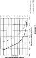
- Figure 3 is a Tafel plot for a low surface area carbon fibre electrode vs a high surface area carbon fibre electrode.
- Figure 4 shows the DCA performance of a low surface area carbon fibre electrode vs a high surface area carbon fibre electrode.
- Figure 5 shows the DCA performance of a full sized low surface area carbon fibre electrode vs that of traditional lead acid batteries currently on the market.
- the battery electrodes or at least the negative electrodes of carbon fibre material having a surface area of less than 30 m 2 /g alone can decrease water consumption, and further that if the carbon fibre material has non-carbon functional groups on the current collector less than 22% as measured by the bulk fibre, the carbon fibre material comprises at least 78% carbon in the bulk fibre, thereby water consumption and gassing may be reduced without a significant reduction in DCA.
- a lead-acid battery can be produced which exhibits water consumption as indicated by battery or cell weight loss, of not more than 16g/Ah or 8g/Ah or 4g/Ah when tested at 60°V ⁇ 2°C over 21 days for a weight loss ⁇ 16g/Ah or under the same conditions over 42 days for a weight loss ⁇ 8g/Ah or ⁇ 4g/Ah, and a minimum DCA acceptance of 0.6 A/Ah.
- the carbon fibre material has impregnated therein an active material comprising a paste comprising Pb-based particles and a fluid such as water, an acid and/or alcohol.
- the acid is dilute sulphuric acid, being water and sulphuric acid.
- the alcohol is ethanol.
- the pasted carbon fibre material has a pasted density of between 1-5 g/cm 3 , or between 2-5 g/cm 3 , or between 2.5-4.5gm/cm 3 , or between 3.5-4.5 gm/cm 3 , or between 3.8-4.2 gm/cm 3 .
- the carbon fibre material comprises a carbon fibre material comprising or derived from a rayon, polyacrylonitrile, phenol resin, or pitch material.
- the carbon fibre material also has an average spacing between conductive fibres in the range about 0.5 to about 10 times or about 5 and about 10 times the average fibre diameter, or less than about 20 microns, or less than about 10 microns, and an average conductive fibre diameter of less than about 10 microns.
- the carbon fibre material has an average thickness less than about 5 mm or less than 3mm or less than 2mm, and a variation in thickness less than about 0.5 mm or less than about 0.2 mm, or alternatively a variation in thickness of less than about 20%.
- the conductive current collecting material fibres are inherently conductive.
- the electrode fibres are carbon fibres.
- the current collector material and the fibres thereof are flexible, which will assist in accommodating volume changes of the active material attached to the current collector material during battery cycling, and the microscale fibres may also reinforce the active material, both properties assisting to reduce breaking off ("shedding") of active material from the electrode in use.
- the negative electrode or electrodes, the positive electrode or electrodes, or both, of a cell or battery may be formed as above.
- the conductive fibrous material comprises the sole current collector of the electrode.
- the electrode may comprise a metal grid also as a current collector in addition to the conductive fibrous material of carbon fibre.
- conductive fibrous material comprises a carbon fibre material and the metal grid comprises a lead grid. The carbon fibre layer(s) are conductively connected to the metal grid so that the grid receives current from the carbon fibre layer(s) and connects the electrode externally thereof.
- the negative or positive or both electrodes of each cell may comprise a metal grid.
- the electrode comprises a metal grid preferably at least 20% of the current generating active mass is dispersed through the conductive fibrous material. In preferred embodiments of the invention at least 40%, 50%, 80%, or more than 80% of the active mass is dispersed in the conductive fibrous material. Thus less than 80%, 60%, 50%, or 20% of the active mass may be dispersed in the metal grid (specifically, within its apertures).
- At least 20% but not more than 40% of the active mass is dispersed through the conductive fibrous material.
- the conductive fibrous material is present as multiple layers of one or more on either side of the metal grid.
- the conductive fibrous material is present as a single layer on one side of the metal grid.
- the metal grid may have a similar superficial surface area or be of similar height and width dimensions particularly in a major plane, to the conductive fibrous material element(s) but in alternative embodiments of the invention the metal grid may have smaller dimensions for example of smaller height and width dimensions, and may comprise for example a narrower lead strip between two larger carbon fibre layers on either side thereof.
- the current collector material is impregnated under pressure with the paste, which in a preferred form comprises a mixture of Pb and PbO particles of Pb and PbO and a fluid such as water, an acid such as for example dilute sulfuric acid, and/or an alcohol.
- the alcohol is ethanol.
- the paste may comprise lead sulphate (PbSO 4 ) particles and a fluid such as water, an acid such as for example dilute sulphuric acid, and/or an alcohol.
- the paste at impregnation into the electrode comprises dilute sulphuric acid comprising between greater than 0% and about 5%, or between 0.25% and about 4%, or between 0.5% and about 4%, or between 0.5 and 3.5% by weight of the paste of sulphuric acid.
- the Pb-based particles may comprise milled or chemically formed particles which may have a mean size of 10 microns or less, small enough to fit easily into spaces between the fibres.
- the paste may optionally also contain other additives such as barium sulphate, and/or an expander such as a lignosulphonate.
- barium sulfate acts as a seed crystal for lead sulphate crystallisation, encouraging the lead to lead sulfate reaction.
- An expander helps prevents agglomeration of sulphate particles at the negative plate, for example forming a solid mass of lead sulfate during discharge into the carbon fibre material.
- an expander may comprise between about 0.01% to about 0.25% or about 0.07% to 0.25%, or about 0.08% to 0.2%, or about 0.08 to 0.2% or about 0.08 to 0.15% by weight of the paste at impregnation. It has been found that the inclusion of an expander compound in the paste may have a beneficial effect on CCA performance but a negative effect on DCA performance. Conventionally an expander at a concentration of around 0.2% or more is added to the paste. It has been found that an expander concentration of between about 0.01% to about 0.15% by weight of the paste at impregnation then both good DCA and CCA performance can be achieved.
- the paste may also comprise Ag, Bi, Zn, or a compound of any thereof as an anti-gassing agent.
- the paste may have a sufficiently low shear strength to flow (slump) when placed in a cylindrical shape on a horizontal surface under gravity. A sufficient slump is seen for a noticeable slumping of a 30mm high by 30mm diameter cylinder, at impregnation into the electrode material.
- the paste has a creamy consistency. It has been found that this is achieved where the paste at impregnation into the electrode comprises (greater than 0 but) less than about 5% by weight of sulphuric acid. It has been found that where the acid content approaches 5% by weight, the paste viscosity increases.
- a fluidiser may be added to the paste to ensure that the paste viscosity remains relatively low to facilitate continuous paste infiltration into the carbon material.
- a suitable fluidiser may for example be polyaspartic acid, added to the paste in the range from greater than 0 but less than about 5% by weight of the lead containing component of the paste.
- the polyaspartic acid may be between about 0.05% to about 4%, or between about 0.75% to about 3%, or between about 1% to about 2.5%.
- the fluidiser preferably should not adversely affect battery performance parameters particularly CCA, DCA, water consumption, and capacity. It has also been found useful when mixing the Pb-based particles, sulphuric acid, water and any optional additives to form the paste, to aid mixing by vibration of the paste during mixing.
- cell formation occurs first by building the conducting framework, taking up most of the Pb in the negative active material, building normally over lengths of several millimetres (connecting strings of perhaps a thousand or more micron sized particles end to end). This stage also produces small PbSO 4 particles. Second, these smaller particles attach to this conductive framework to provide and receive current.
- the electrode comprises, when fully charged, voidage (being the fractional volume occupied by the pores between the lead and conductive fibres) of between about at least about 0.3, and a mass loading ratio of lead (in whatever form) to the mass of conductive fibres, when converted to volume ratio, in the range about 0.7:1 or about 1:1 to about 15:1 or about 10:1 (each over at least a major fraction of the electrode and more preferably over substantially all of the electrode).
- the voidage is between about 0.3 and about 0.9, about 0.3 and about 0.85, more preferably between about 0.3 and about 0.8, more preferably between about 0.5 and about 0.85, more preferably between about 0.6 and about 0.90, more preferably between about 0.65 and about 0.95, further preferably between about 0.7 and about 0.98.
- the volume loading ratio of the active material when converted to Pb to conductive fibres is between about 0.7 :1 or about 1:1 and about 7:1, or about 1.5:1 and about 5:1, or about 2:1 and about 4:1.
- the voidage may be present as corridors to form between the lead and carbon to enable lead particles to form between each of the carbon fibres.
- electrodes of the invention whether composite (also incorporating a metal grid) or non-composite (without a metal grid) have a thickness (transverse to a length and width or in plane dimensions of the electrode) many times such as 10, 20, 50, or 100 times less than the or any in plane dimension of the electrode.
- the electrode thickness may be less than 5 or less than 3 mm for example.
- Each of the in plane length and width dimensions of the electrode may be greater than 50 or 100 mm for example.
- Such electrodes have a planar form with low thickness.
- One form of composite electrode of the invention may comprise a metal grid of thickness about 3.5mm or less such as about 0.5mm mm thick, with a carbon fibre layer of thickness about 2 mm or less such as about 0.3 mm thick on either side.
- the electrode is substantially planar and has a dimension from a metal lug for external connection along at least one edge of the electrode less than 150mm, or less than 120mm, or less than 100 mm, or less than 70 mm, or less than 50 mm, or about 30 mm or less for example (with or without a macro-scale current collector).
- a planar form may be formed into a cylindrical electrode for example.
- cells and/or batteries comprising an electrode construction of the invention may have both improved or relatively high DCA (measured by the Ford EU DCA test that has now been converted into a standard EU test being EN50432-6:2015 Test 7.3.10 for example) and low water consumption (measured in accordance with EN50432-1:2015 Test 6.9) and/or CCA (measured in accordance with the SAE J357 CCA test for example) and/or may maintain DCA or a higher rate of DCA with increasing number of charge-discharge cycles, and may also have improved or relatively high VED and/or improved battery life.
- DCA measured by the Ford EU DCA test that has now been converted into a standard EU test being EN50432-6:2015 Test 7.3.10 for example
- CCA measured in accordance with the SAE J357 CCA test for example
- Embodiments of cells or batteries of the invention may maintain DCA at least 70 % or 80% or 90% of starting DCA (when first fully charged) after 5000 or 10000 cycles for example.
- the capacity of a battery is measured in Amp/hours, and utilisation is the actual battery capacity divided by the theoretical maximum capacity.
- the cells or batteries of the invention may have increased utilisation such as a utilisation of at least 55%, 60%, 70%, or 80% or over.
- Pasted electrodes referred to subsequently in this example were constructed as follows: Paste was prepared using leady oxide, dilute sulphuric acid, and 0.1% by weight lignosulphonate as an expander, and ⁇ 1g of barium sulphate. The paste was mixed in an ultrasound bath to achieve an even consistency. Unpasted carbon fibre material, with areal density of approximately 200g/m2, was then placed on the ultrasound plate, paste was then spread onto the carbon fibre, and then the ultrasound was turned on to vibrate the paste into the fabric for approximately ⁇ 1.5 ⁇ 2.0 min. The pasted electrode was turned over a couple of times while the ultra-sound was in operation until a smooth distribution of paste was observed where the majority of paste had penetrated into the fabric.
- the total amount of wet mass loaded into the electrode achieved a capacity (low current discharging) of approximately 14 Ah (i.e. approx., 62% of the theoretical capacity).
- the pasted electrode active area had dimensions length 140 mm, width 100 mm, and thickness between 2-2.5 mm.
- the achieved lead loading per volume (pasted density of the electrode based on the mass loaded into the electrode) was approx. 2.5-3g/cm 3 .
- the Negative Active Mass (NAM) Pb to carbon volume ratio was around 4 to 6.
- the average spacing between carbon fibres was about 30 microns.
- the electrode was then air-dried for 24 hours at ambient temperature (18 ⁇ 24°C).
- the electrolyte was replaced with 1.28 sg H 2 SO 4 and stabilised over one cycle of low current discharging (0.1C) prior to being sent for DCA and water consumption testing.
- Formation is the first time the electrochemically active materials experience a charging current/voltage, and for the negative electrode involves the conversion of the Leady Oxide pasted material into Pb.
- the electrical charge initially converts the active material to Pb.
- Pb Towards the end of formation, most, if not all, of the active material is Pb and any current still flowing is because water is being converted into H 2 and O 2 .
- the "asymptotic current" at the end of formation is therefore a strong predictor of the likely water consumption outcome for the battery; the higher the asymptotic current, the higher the water consumption.
- Acid of high grade (low metal impurities) suitable for battery production was used.
- the cell was held at a temperature of 25°C and an overpotential of -150 mV with respect to the Pb/PbSO 4 electrode (- 1.15 V vs the reference electrode) was applied to the felt electrode using a Gamry Interface 1000 potentiostat, as this overpotential is typically what is experienced by the negative electrode during water consumption testing at battery scale.
- the steady state current that resulted from the applied overpotential was used.
- Carbon felt/lead based active material electrodes for water consumption - Tafel test is used as a relatively quick method for determining the water consumption rate that will be achieved in a full battery. The advantage of this test is that useful data can be generated in less than one week.
- the full EN50432-1:2015 water consumption test which is the actual standard against which the batteries will be assessed, can take up to 7 weeks to conduct.
- samples of carbon fibre/Pb electrodes were made as described in the Electrode construction section above, with dimensions of 140 mm x 100 mm. Cells were constructed with one such CF/Pb negative electrode sandwiched between two commercially available automotive positive electrodes, with Daramic separators between each electrode surface.
- a silver/silver sulphate reference electrode was inserted in the cell. Acid of high grade suitable for battery production was used. The cells were connected to a testing machine (Arbin BT2000) and electrochemically formed. Tafel tests were done both at 25 and 60°C. A steady state current for an application of -170 mV (the typical overpotential experienced by the negative electrode during the EN50432-1:2015 water consumption test) was noted as the current generated at this overpotential is predictive of the water consumption that will be experienced. (The current generated by applying an overpotential to a fully charged lead acid battery is due to hydrolysis (converting H 2 O into H 2 at the negative electrode, and O 2 at the positive electrode, rather than faradaic reactions (converting PbSO 4 into Pb at the negative electrode). The larger the steady state current, the greater the amount of hydrolysis, and the higher the water consumption will be.
- Electrode CF01- not according to the invention Electrode CF02- not according to the invention
- Electrode CF04- not according to the invention Electrode CF05
- Electrochemical Data (fabric only) mA/g 1.56 4.2 6.88 0.43 Specific Surface Area via BET (m2/g) 0.42 0.3 66 91.61 0.42
- Elemental Carbon as a % in the bulk fibre 87 78 84 97
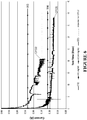
- Figure 6 is a water consumption plot for electrodes CF02 and CF05 with actual and projected data that can be used to determine water consumption in g/Ah with the reference standards W3 and W4 provided.
- Figure 6 shows the current that is generated by applying a constant voltage of 2.4V for the duration of the test, as described above. As the battery is fully charged before the test begins, any current flowing is due to the conversion of H 2 O into H 2 and O 2 i.e. due to hydrolysis. The higher the current, therefore, the higher the water consumption.
- the average current flowing over 42 days needs to be 119mA or less.
- the average current over the 42 days is 237mA or less.
- electrode CF02 both actual and projected water consumption of 7g/Ah (calculated as an average area under the curve) where the W3 line runs at 8g/Ah that correlates to a current of 237mA (representing the asymptotic current).
- DCA is maintained above the traditional lead grid lead acid battery value of 0.6A/Ah.
- Samples of carbon fibre felt that were treated at the temperatures indicated on the x-axis of Figures 7 and 8 were obtained and cut to 140mm length by 100m width.
- the electrodes were pasted as described in Example 1 and then underwent water consumption testing in accordance with the methods described in Example 1. Again the water testing was carried out at 25 ⁇ C with a steady state current over potential of -170mV.
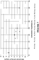
- Figure 7 is a water consumption plot for various pasted carbon fibre electrodes made from carbon fibre materials that have been treated at varying temperature ranges starting from 970 ⁇ C to approx., 2300 ⁇ C.
- Figure 8 is a plot of carbonisation versus temperature for the carbon fibre materials.
- Carbonisation temperature is an important parameter as the higher the carbonisation temperature, the higher the Carbon content (bulk measurement) and the lower the non-Carbon content. Hence, the higher the carbonisation temperature, the lower the non-Carbon content and the lower the observed gassing rate.
- Figure 7 shows, a trend of decreased water consumption as the temperature of carbonisation increases was found.
- Figure 7 shows the Hydrogen Evolution Current (HER) which is the stable current that is observed from pasted electrodes that are subjected to a charging overpotential for the negative electrode of 170mV, a typical overpotential for batteries in Micro Hybrid Vehicles. From Figure 8 it can be seen that there is a trend for those electrodes carbonised at a temperature at or above 1400°C are likely to produce a battery product having a water consumption of 3g/Ah. This is indicated by a water consumption of approximately 0.25 mA/g.Pb.
- HER Hydrogen Evolution Current
Landscapes
- Chemical & Material Sciences (AREA)
- Chemical Kinetics & Catalysis (AREA)
- Electrochemistry (AREA)
- General Chemical & Material Sciences (AREA)
- Engineering & Computer Science (AREA)
- Materials Engineering (AREA)
- Manufacturing & Machinery (AREA)
- Battery Electrode And Active Subsutance (AREA)
- Cell Electrode Carriers And Collectors (AREA)
Description
- The invention relates to an improved electrode of carbon fibre for use in the manufacture or construction of lead-acid batteries particularly but not exclusively automotive batteries for hybrid vehicles.
- Vehicle hybridisation driven by increasing worldwide demand for lower automotive emissions and/or increased fuel economy places increased demand on vehicle batteries, which are most commonly Pb-acid batteries. Overcharging a Pb-acid battery, including charging a Pb-acid battery at a rate of charge greater than the battery can accept, can lead to breaking down of water in the electrolyte to hydrogen and oxygen gas, consuming water in the electrolyte which in a closed battery cannot be replaced, permanently reducing the battery capacity. Overcharging also evolves hydrogen and oxygen gas (gassing) which is dangerous and for which venting from the battery is provided.
- Hybrid and fully electric vehicles typically employ regenerative braking, in which when a braking force is applied by a generator (which here includes an alternator), the electric energy from which recharges the vehicle battery. Under regenerative braking relatively high charging currents may be generated and thus batteries for hybrid vehicles with regenerative braking should also have a high dynamic charge acceptance (DCA) rate, which refers to the rate at which a battery will accept charge. As companies began developing batteries with high DCA performance, it became apparent that improved DCA came at the expense of unacceptably high water consumption. By around the beginning of 2015, the requirement for a "high DCA" battery had morphed into a requirement for a "high DCA, low water consumption" battery. Additionally, these batteries must also meet the other automotive battery parameters of good cold cranking amps (CCA), high cycle life and good volumetric energy density (VED). In a Pb-acid battery DCA is primarily determined by the charging reaction at the negative electrode. Increased demands driven by the automotive industry for such batteries with increasingly low water consumption under demanding test conditions are being made.
- Our international patent application publication
WO2011/078707 (alsoUS2013/004842 ) discloses a lead-acid battery comprising as a current collector a conductive fibrous material of filaments with low interfibre spacing and conducting chains of Pb-based particles attached to the fibres, which provides improved battery performance particularly DCA. Our international patent application publicationWO2014/042542 andUS patent application publication 2015/0017545 also disclose a lead-acid battery comprising as a current collector a conductive fibrous material, impregnated with an active material.US patent application publication 2014/0093775 discloses active material compositions comprising low surface area carbonaceous material in the active material composition. - It is an object of at least some embodiments of the invention to provide improved or at least alternative electrodes and/or cells and/or batteries particularly but not necessarily exclusively suitable for use in hybrid vehicles, and/or methods for manufacturing same.
- The invention is set out in the appended claim. The invention comprises a lead-acid battery or cell including at least one electrode comprising a carbon fibre fabric material having impregnated therein an active material comprising a paste comprising Pb-based particles and dilute sulphuric acid characterised in that the carbon fibre fabric material has a surface area of less than 5m2/g when measured using the Braunauer-Emmett-Teller methodology, and an areal density of less than 500gm/m2, and in that non-carbon functional groups on the carbon fibre fabric material comprise less than 20% by mass of the bulk fibre and the carbon fibre fabric material comprises at least 80% carbon by mass in the bulk fibre when analysed via X-ray Photoelectron Spectroscopy.
- In at least some embodiments of the invention the carbon fibre material and/or carbon material in the active mass, has been heat treated to a temperature of at least 1000°C, at least 1050°C, or at least 1100°C or at least 1200°C, or at least 1400°C or least 1500°C or at least 1600°C.
- In at least some embodiments of the invention the carbon fibre material comprises a polyacrylonitrile (PAN) carbon fibre material, a rayon, phenol resin or pitch material.
- In at least some embodiments of the invention the current collector carbon fibre material comprises at least 85%, or at least 90%, or at least 95%, or at least 97%, or at least 98% carbon by mass of the bulk fibre.
- Also disclosed herein, but not independently claimed, is a lead-acid battery or cell including at least one electrode comprising a carbon fibre material, wherein:
- the carbon fibre material has a surface area of less than 20 m2/g, and
- non-carbon functional groups in the carbon fibre material comprise less than 20% by mass in the bulk fibre, and the carbon fibre material comprises at least 80% carbon by mass in the bulk fibre.
- In at least some embodiments of the invention the carbon fibre material has a surface area of less than 20 m2/g, or less than 10 m2/g, or less than 5 m2/g, or less than 3 m2/g, or less than 1 m2/g (as determined by the BET method for example).
- In at least some embodiments of the invention the non-carbon functional groups in carbon fibre material comprise less than 15% in the bulk fibre, or less than 10% in the bulk fibre, or less than 5% in the bulk fibre or less than 3% of the bulk fibre or less than 2% in the bulk fibre.
- In at least some embodiments of the invention the carbon fibre material comprises at least 85%, or at least 90% carbon by mass in the bulk fibre.
- In at least some embodiments of the invention the metal impurities comprise less than 800ppm, or less than 500ppm, or less than 100ppm, or less than 80ppm, or less than 50ppm, or less than 30 ppm, or less than 20ppm. Undesirable metal impurities comprise for example, Fe, Co, Ni, Ag, Cu.
- In at least some embodiments of the invention the areal density of the carbon fibre material is less than 400gm/m2, or less than 300 gm/m2, or less than 250gm/m2, or less than 200gm/m2, or less than 150gm/m2.
- Also disclosed herein, but not independently claimed, is a lead-acid battery or cell including at least one electrode comprising as a current collector a carbon fibre material and/or carbon material in the active mass, which exhibits water consumption as indicated by battery or cell weight loss, of not more than 16g/Ah when tested at 60°C + 2°C over 21 days. Also disclosed herein, but not independently claimed, is a lead-acid battery or cell including at least one electrode comprising as a current collector a carbon fibre material having a minimum DCA acceptance of 0.6 A/Ah and a water consumption of not more than 16g/Ah (when tested according to European standard EN50432-1:2015 Test 6.9). In at least some embodiments of the invention water consumption of a lead-acid battery or cell of the invention is not more than 8g/Ah when tested at 60°C + 2°C over 42 days, or is not more than 4g/Ah when tested at 60 + 2C over 42 days, is not more than 3g/Ah when tested at 60°C + 2°C over 42 days, or is not more than 4g/Ah when tested at 60°C ± 2°C over 84 days. In the alternative, in at least some embodiments of the invention the water consumption is not more than 300mA, or is not more than 250mA, or is not more than 200mA, or is not more than 150mA, or is not more than 100mA, or is not more than 90mA, where these values represent the average current for a 12V 60Ah battery.
- Also disclosed herein, but not independently claimed, is a carbon fibre material having impregnated therein an active material comprising a paste comprising Pb-based particles and a fluid such as water, a dilute acid such as for example sulphuric acid and water, and/or an alcohol. In some embodiments of the invention the alcohol is ethanol. In at least some embodiments of the invention the pasted carbon fibre material has a pasted density of between 1-5 g/cm3, or between 2-5 g/cm3, or between 2.5-4.5gm/cm3, or between 3.5-4.5 gm/cm3, or between 3.8-4.2 gm/cm3.
- In at least some embodiments of the invention, cells and/or batteries comprising an electrode construction of the invention may have a combination of relatively high DCA (and/or may maintain DCA or a higher rate of DCA with an increasing number of charge-discharge cycles) and relatively low water consumption.
- In some embodiments of the invention, the paste comprises carbon particles; or the paste comprises carbon particles which have a surface area in the
range 50 to 1500 m2/gr and/or the total specific carbon surface area in the paste impregnated electrode is less than 5 m2/g; and/or the pasted carbon fibre material has a pasted density of between 1-5 g/cm3. - The term "carbonisation" as used in this specification refers to increasing the proportion of carbon in the bulk mass of carbon fibre material that has been treated.
- The term "comprising" as used in this specification means "consisting at least in part of'. When interpreting each statement in this specification that includes the term "comprising", features other than that or those prefaced by the term may also be present. Related terms such as "comprise" and "comprises" are to be interpreted in the same manner.
- The invention is further described with reference to the accompanying figures by way of example wherein:
-
Figure 1 shows an embodiment of a carbon fibre material electrode, -
Figure 2 is a schematic cross-section of an electrode comprising multiple layers of carbon fibre material, -
Figure 3 shows a Tafel Plot of a low surface area carbon fibre electrode vs a high surface area carbon fibre electrode, -
Figure 4 shows the DCA performance of a low surface area carbon fibre electrode vs a high surface area carbon fibre electrode, -
Figure 5 shows the DCA performance of a full sized low surface area carbon fibre electrode vs that of traditional lead acid batteries currently on the market, -
Figure 6 is a water consumption plot for electrodes CF02 and CF05 referred to in Example 1 in the subsequent description of experimental work, with actual and projected data that can be used to determine water consumption in g/Ah with the reference standards W3 and W4 provided, -
Figure 7 is a water consumption plot for various pasted carbon fibre electrodes that have been built using carbon fibre materials treated at temperatures between 970 ○C and approx., 2300 ○C as referred to in Example 2 in the subsequent description of experimental work, and -
Figure 8 is a plot of carbonisation versus temperature for the carbon fibre materials subsequently used to form the electrodes as set out in the Examples. -
Figure 1 shows a section of a conductive fibre electrode such as ofcarbon fibre material 1, for a Pb-acid cell or battery, with one form oflug 2 for external connection of the electrode, formed on the fibre material.Figure 2 is a schematic cross-section of a similar electrode comprisingmultiple layers 1 of fibre material, and alug 2. The lug is formed of metal such as Pb or a Pb alloy (herein both referred to inclusively as Pb) but may be formed of another material which electrically connects preferably by penetration into and/or between the fibrous material. Preferably substantially all or at least a majority of the fibres of the electrode material extend continuously across the electrode to thelug 2. The electrodes ofFigures 1 and 2 are shown by way of example only. - It will appreciated that the electrode shown in
Figure 2 may also comprise a single layer of carbon fibre material that is then provided with a lug in accordance with that described above. Such a single layer of material may be woven or non-woven (such as for example felted, hydroentangled, or needle punched), or knitted. - In accordance with an aspect of the invention the
carbon fibre material 1 the current collector a carbon fibre material and/or carbon material in the active mass, has been heat treated to a temperature of at least 1000°C, 1100°C, 1200°C, 1400°C, 1500°C, or 1600°C (referred to herein as carbonisation). This is effective to reduce non-carbon functional groups on the carbon fibre material to less than 22% by mass of the carbon fibre material so that the carbon fibre material comprises at least 78% carbon in the bulk fibre. - The carbon fibre material consists of nano-sized regions of graphitic sheets, with the regions linked together by nongraphitic carbon. The top and bottom surfaces of the graphitic regions generally comprise aromatic C-C bonds (these do not contribute to gassing). On the edges of these sheets - these bonds are specific and allow the carbon to mate up with other non-carbon chemical functional groups or moieties ― namely nitrogen and oxygen groups which (we believe) contributes to gassing.
- Removal of the non-carbon functional groups can be undertaken by a temperature controlled process in an inert atmosphere. The inert atmosphere ensures the carbon does not react with anything else. With reference to
Figure 7 and Table 1 below, the heat treatment minimises the edge groupings because (we believe) the high temperature creates larger graphite sheets so the same mass of carbon remains but the carbon is now spread over a larger volume. Therefore there is a natural minimisation in the number of carbon edges/unit volume or unit area. This reduction of edge area can be measured using BET. - In accordance with another aspect the invention is a low surface area carbon fibre electrode, i.e., having a surface area of less than 30 m2/g, that alone can reduce water consumption.
Figure 3 is a Tafel plot for a low surface area carbon fibre electrode vs a high surface area carbon fibre electrode.Figure 4 shows the DCA performance of a low surface area carbon fibre electrode vs a high surface area carbon fibre electrode.Figure 5 shows the DCA performance of a full sized low surface area carbon fibre electrode vs that of traditional lead acid batteries currently on the market. - In summary we have found that by forming the battery electrodes or at least the negative electrodes of carbon fibre material having a surface area of less than 30 m2/g alone can decrease water consumption, and further that if the carbon fibre material has non-carbon functional groups on the current collector less than 22% as measured by the bulk fibre, the carbon fibre material comprises at least 78% carbon in the bulk fibre, thereby water consumption and gassing may be reduced without a significant reduction in DCA. For example a lead-acid battery can be produced which exhibits water consumption as indicated by battery or cell weight loss, of not more than 16g/Ah or 8g/Ah or 4g/Ah when tested at 60°V ± 2°C over 21 days for a weight loss <16g/Ah or under the same conditions over 42 days for a weight loss <8g/Ah or <4g/Ah, and a minimum DCA acceptance of 0.6 A/Ah.
- In at least some embodiments of the invention the carbon fibre material has impregnated therein an active material comprising a paste comprising Pb-based particles and a fluid such as water, an acid and/or alcohol. In some embodiments of the invention the acid is dilute sulphuric acid, being water and sulphuric acid. In some embodiments of the invention the alcohol is ethanol. In at least some embodiments of the invention the pasted carbon fibre material has a pasted density of between 1-5 g/cm3, or between 2-5 g/cm3, or between 2.5-4.5gm/cm3, or between 3.5-4.5 gm/cm3, or between 3.8-4.2 gm/cm3.
- In at least some embodiments of the invention the carbon fibre material comprises a carbon fibre material comprising or derived from a rayon, polyacrylonitrile, phenol resin, or pitch material.
- In at least some embodiments of the invention the carbon fibre material also has an average spacing between conductive fibres in the range about 0.5 to about 10 times or about 5 and about 10 times the average fibre diameter, or less than about 20 microns, or less than about 10 microns, and an average conductive fibre diameter of less than about 10 microns.
- In at least some embodiments of the invention the carbon fibre material has an average thickness less than about 5 mm or less than 3mm or less than 2mm, and a variation in thickness less than about 0.5 mm or less than about 0.2 mm, or alternatively a variation in thickness of less than about 20%.
- In preferred embodiments of the invention the conductive current collecting material fibres are inherently conductive. In preferred embodiments of the invention the electrode fibres are carbon fibres.
- Preferably the current collector material and the fibres thereof are flexible, which will assist in accommodating volume changes of the active material attached to the current collector material during battery cycling, and the microscale fibres may also reinforce the active material, both properties assisting to reduce breaking off ("shedding") of active material from the electrode in use.
- The negative electrode or electrodes, the positive electrode or electrodes, or both, of a cell or battery may be formed as above.
- In some embodiments of the invention the conductive fibrous material comprises the sole current collector of the electrode. Alternatively the electrode may comprise a metal grid also as a current collector in addition to the conductive fibrous material of carbon fibre. In preferred embodiments of the invention conductive fibrous material comprises a carbon fibre material and the metal grid comprises a lead grid. The carbon fibre layer(s) are conductively connected to the metal grid so that the grid receives current from the carbon fibre layer(s) and connects the electrode externally thereof.
- The negative or positive or both electrodes of each cell may comprise a metal grid.
- Where the electrode comprises a metal grid preferably at least 20% of the current generating active mass is dispersed through the conductive fibrous material. In preferred embodiments of the invention at least 40%, 50%, 80%, or more than 80% of the active mass is dispersed in the conductive fibrous material. Thus less than 80%, 60%, 50%, or 20% of the active mass may be dispersed in the metal grid (specifically, within its apertures).
- In some embodiments of the invention at least 20% but not more than 40% of the active mass is dispersed through the conductive fibrous material.
- In preferred embodiments of the invention the conductive fibrous material is present as multiple layers of one or more on either side of the metal grid. Alternatively the conductive fibrous material is present as a single layer on one side of the metal grid.
- The metal grid may have a similar superficial surface area or be of similar height and width dimensions particularly in a major plane, to the conductive fibrous material element(s) but in alternative embodiments of the invention the metal grid may have smaller dimensions for example of smaller height and width dimensions, and may comprise for example a narrower lead strip between two larger carbon fibre layers on either side thereof.
- During battery or cell construction the current collector material is impregnated under pressure with the paste, which in a preferred form comprises a mixture of Pb and PbO particles of Pb and PbO and a fluid such as water, an acid such as for example dilute sulfuric acid, and/or an alcohol. In some embodiments of the invention the alcohol is ethanol. Alternatively the paste may comprise lead sulphate (PbSO4) particles and a fluid such as water, an acid such as for example dilute sulphuric acid, and/or an alcohol. In some embodiments of the invention the paste at impregnation into the electrode comprises dilute sulphuric acid comprising between greater than 0% and about 5%, or between 0.25% and about 4%, or between 0.5% and about 4%, or between 0.5 and 3.5% by weight of the paste of sulphuric acid. The Pb-based particles may comprise milled or chemically formed particles which may have a mean size of 10 microns or less, small enough to fit easily into spaces between the fibres.
- The paste may optionally also contain other additives such as barium sulphate, and/or an expander such as a lignosulphonate. Barium sulfate acts as a seed crystal for lead sulphate crystallisation, encouraging the lead to lead sulfate reaction. An expander helps prevents agglomeration of sulphate particles at the negative plate, for example forming a solid mass of lead sulfate during discharge into the carbon fibre material.
- For example an expander may comprise between about 0.01% to about 0.25% or about 0.07% to 0.25%, or about 0.08% to 0.2%, or about 0.08 to 0.2% or about 0.08 to 0.15% by weight of the paste at impregnation. It has been found that the inclusion of an expander compound in the paste may have a beneficial effect on CCA performance but a negative effect on DCA performance. Conventionally an expander at a concentration of around 0.2% or more is added to the paste. It has been found that an expander concentration of between about 0.01% to about 0.15% by weight of the paste at impregnation then both good DCA and CCA performance can be achieved.
- The paste may also comprise Ag, Bi, Zn, or a compound of any thereof as an anti-gassing agent.
- The paste may have a sufficiently low shear strength to flow (slump) when placed in a cylindrical shape on a horizontal surface under gravity. A sufficient slump is seen for a noticeable slumping of a 30mm high by 30mm diameter cylinder, at impregnation into the electrode material. Preferably the paste has a creamy consistency. It has been found that this is achieved where the paste at impregnation into the electrode comprises (greater than 0 but) less than about 5% by weight of sulphuric acid. It has been found that where the acid content approaches 5% by weight, the paste viscosity increases.
- A fluidiser may be added to the paste to ensure that the paste viscosity remains relatively low to facilitate continuous paste infiltration into the carbon material. A suitable fluidiser may for example be polyaspartic acid, added to the paste in the range from greater than 0 but less than about 5% by weight of the lead containing component of the paste. In other embodiments of the invention the polyaspartic acid may be between about 0.05% to about 4%, or between about 0.75% to about 3%, or between about 1% to about 2.5%. The fluidiser preferably should not adversely affect battery performance parameters particularly CCA, DCA, water consumption, and capacity. It has also been found useful when mixing the Pb-based particles, sulphuric acid, water and any optional additives to form the paste, to aid mixing by vibration of the paste during mixing.
- During initial cell formation (first charge and discharge cycle during which active particle linkages form) after cell or battery construction, cell formation occurs first by building the conducting framework, taking up most of the Pb in the negative active material, building normally over lengths of several millimetres (connecting strings of perhaps a thousand or more micron sized particles end to end). This stage also produces small PbSO4 particles. Second, these smaller particles attach to this conductive framework to provide and receive current.
- In at least some embodiments of the invention the electrode comprises, when fully charged, voidage (being the fractional volume occupied by the pores between the lead and conductive fibres) of between about at least about 0.3, and a mass loading ratio of lead (in whatever form) to the mass of conductive fibres, when converted to volume ratio, in the range about 0.7:1 or about 1:1 to about 15:1 or about 10:1 (each over at least a major fraction of the electrode and more preferably over substantially all of the electrode). In at least some embodiments of the invention the voidage is between about 0.3 and about 0.9, about 0.3 and about 0.85, more preferably between about 0.3 and about 0.8, more preferably between about 0.5 and about 0.85, more preferably between about 0.6 and about 0.90, more preferably between about 0.65 and about 0.95, further preferably between about 0.7 and about 0.98. In at least some embodiments of the invention the volume loading ratio of the active material when converted to Pb to conductive fibres is between about 0.7 :1 or about 1:1 and about 7:1, or about 1.5:1 and about 5:1, or about 2:1 and about 4:1. The voidage may be present as corridors to form between the lead and carbon to enable lead particles to form between each of the carbon fibres.
- In some embodiments of the invention electrodes of the invention whether composite (also incorporating a metal grid) or non-composite (without a metal grid) have a thickness (transverse to a length and width or in plane dimensions of the electrode) many times such as 10, 20, 50, or 100 times less than the or any in plane dimension of the electrode. The electrode thickness may be less than 5 or less than 3 mm for example. Each of the in plane length and width dimensions of the electrode may be greater than 50 or 100 mm for example. Such electrodes have a planar form with low thickness. One form of composite electrode of the invention may comprise a metal grid of thickness about 3.5mm or less such as about 0.5mm mm thick, with a carbon fibre layer of thickness about 2 mm or less such as about 0.3 mm thick on either side.
- In preferred forms the electrode is substantially planar and has a dimension from a metal lug for external connection along at least one edge of the electrode less than 150mm, or less than 120mm, or less than 100 mm, or less than 70 mm, or less than 50 mm, or about 30 mm or less for example (with or without a macro-scale current collector). Alternatively such a planar form may be formed into a cylindrical electrode for example.
- As stated, in preferred forms suitable for use in hybrid vehicles cells and/or batteries comprising an electrode construction of the invention may have both improved or relatively high DCA (measured by the Ford EU DCA test that has now been converted into a standard EU test being EN50432-6:2015 Test 7.3.10 for example) and low water consumption (measured in accordance with EN50432-1:2015 Test 6.9) and/or CCA (measured in accordance with the SAE J357 CCA test for example) and/or may maintain DCA or a higher rate of DCA with increasing number of charge-discharge cycles, and may also have improved or relatively high VED and/or improved battery life. Embodiments of cells or batteries of the invention may maintain DCA at least 70 % or 80% or 90% of starting DCA (when first fully charged) after 5000 or 10000 cycles for example. The capacity of a battery is measured in Amp/hours, and utilisation is the actual battery capacity divided by the theoretical maximum capacity. In other embodiments of the invention the cells or batteries of the invention may have increased utilisation such as a utilisation of at least 55%, 60%, 70%, or 80% or over.
- The following description of experimental work in which carbon fibre electrodes were constructed and tested for water consumption and DCA is given by way of example and further illustrates the invention.
- Pasted electrodes referred to subsequently in this example were constructed as follows: Paste was prepared using leady oxide, dilute sulphuric acid, and 0.1% by weight lignosulphonate as an expander, and <1g of barium sulphate. The paste was mixed in an ultrasound bath to achieve an even consistency. Unpasted carbon fibre material, with areal density of approximately 200g/m2, was then placed on the ultrasound plate, paste was then spread onto the carbon fibre, and then the ultrasound was turned on to vibrate the paste into the fabric for approximately ~ 1.5 ― 2.0 min. The pasted electrode was turned over a couple of times while the ultra-sound was in operation until a smooth distribution of paste was observed where the majority of paste had penetrated into the fabric. The total amount of wet mass loaded into the electrode achieved a capacity (low current discharging) of approximately 14 Ah (i.e. approx., 62% of the theoretical capacity). The pasted electrode active area had dimensions length 140 mm,
width 100 mm, and thickness between 2-2.5 mm. The achieved lead loading per volume (pasted density of the electrode based on the mass loaded into the electrode) was approx. 2.5-3g/cm3. At the fully charged state of the electrode, the Negative Active Mass (NAM) Pb to carbon volume ratio was around 4 to 6. The average spacing between carbon fibres was about 30 microns. The electrode was then air-dried for 24 hours at ambient temperature (18 ― 24°C). Where the pasted electrode were subsequently assembled in a cell, this contained electrolyte of 1.15 sg H2SO4 with one positive electrode on each side. The cell was left soaking for 24 hours at ambient temperature (18 - 24°C) and standard cell formation was carried out. - The electrolyte was replaced with 1.28 sg H2SO4 and stabilised over one cycle of low current discharging (0.1C) prior to being sent for DCA and water consumption testing.
- A variety of tests were carried out on the carbon fibre fabric before pasting and on the pasted/formed electrodes described above. The test methods for Specific Surface Area, carbon vs non-carbon functional group content, water consumption, and DCA are given below:
- Specific Surface Area: The Specific Surface Area (SSA) of the carbon fibre samples was measured using the Brunauer-Emmett-Teller (BET) methodology (benzene analysis with 5ppm benzene vapour in atmospheric pressure nitrogen at room temperature) to determine the amount of nitrogen that was absorbed.
- Carbon vs non-carbon functional group content: Samples of carbon fibre fabric were crushed into a powder, and then analysed via X-ray Photoelectron Spectroscopy (XPS). This determines the mass by percentage the carbon and non-carbon functional group content of the carbon fibre material as a bulk measurement.
- Water Consumption via electrochemical means, Tafel Method or European Automotive Battery standard: Samples of carbon fibre fabric were tested via electrochemical means as described below. Pending the outcome of the electrochemical test, the carbon fibre fabric underwent testing by the Tafel method. Here the carbon fabric is made into pasted electrodes as set out above and tested to obtain water consumption related values using the Tafel test current densities regime, by the standard Tafel test described in Fernandez, M., Atanassova, P., ALABC Project ref 1012M report no. 1, Mar-Aug 2011. Subject to the results of the Tafel testing, then some electrodes (carbon fibre fabric with Pb paste) were then further tested using the European Automotive Battery standard EN50432-1:2015, Test 6.9.
- DCA: Electrodes were tested for DCA according to the industry standard Ford EU DCA testing regime, the primary elements of which are now embodied in the EU test EN50432-6:2015 Test 7.3.10.
- Formation of Electrodes. Formation is the first time the electrochemically active materials experience a charging current/voltage, and for the negative electrode involves the conversion of the Leady Oxide pasted material into Pb. When electrodes are formed, the electrical charge initially converts the active material to Pb. Towards the end of formation, most, if not all, of the active material is Pb and any current still flowing is because water is being converted into H2 and O2. The "asymptotic current" at the end of formation is therefore a strong predictor of the likely water consumption outcome for the battery; the higher the asymptotic current, the higher the water consumption.
- Evaluating the Water Consumption tendency of the carbon fabric via electrochemical testing: This is a relatively quick test in which a higher the current as measured in mA/g indicates a likelihood of increased gassing. Samples of carbon fibre fabric were cut out and made into electrodes that had superficial surfaces of around 12 mm x 12 mm (and were around 2 mm thick). The samples were submerged in sulphuric acid of SG 1.28. Each sample was pressed onto a copper shim and the contact area was completely covered with epoxy resin so that no electrolyte made contact with the copper. One sample electrode was placed opposite a counter electrode made of woven carbon fibres similarly connected to copper shim. A reference electrode of silver/silver sulphate was also placed within the area between the working and counter electrode. Acid of high grade (low metal impurities) suitable for battery production was used. The cell was held at a temperature of 25°C and an overpotential of -150 mV with respect to the Pb/PbSO4 electrode (- 1.15 V vs the reference electrode) was applied to the felt electrode using a Gamry Interface 1000 potentiostat, as this overpotential is typically what is experienced by the negative electrode during water consumption testing at battery scale. The steady state current that resulted from the applied overpotential.
- Carbon felt/lead based active material electrodes for water consumption - Tafel test: Tafel testing is used as a relatively quick method for determining the water consumption rate that will be achieved in a full battery. The advantage of this test is that useful data can be generated in less than one week. The full EN50432-1:2015 water consumption test, which is the actual standard against which the batteries will be assessed, can take up to 7 weeks to conduct. For the Tafel test, samples of carbon fibre/Pb electrodes were made as described in the Electrode construction section above, with dimensions of 140 mm x 100 mm. Cells were constructed with one such CF/Pb negative electrode sandwiched between two commercially available automotive positive electrodes, with Daramic separators between each electrode surface. Also a silver/silver sulphate reference electrode was inserted in the cell. Acid of high grade suitable for battery production was used. The cells were connected to a testing machine (Arbin BT2000) and electrochemically formed. Tafel tests were done both at 25 and 60°C. A steady state current for an application of -170 mV (the typical overpotential experienced by the negative electrode during the EN50432-1:2015 water consumption test) was noted as the current generated at this overpotential is predictive of the water consumption that will be experienced. (The current generated by applying an overpotential to a fully charged lead acid battery is due to hydrolysis (converting H2O into H2 at the negative electrode, and O2 at the positive electrode, rather than faradaic reactions (converting PbSO4 into Pb at the negative electrode). The larger the steady state current, the greater the amount of hydrolysis, and the higher the water consumption will be.
- Water Consumption via European Automotive Battery standard, EN50432-1:2015: 60Ah cells (being a typical capacity of a Micro Hybrid Battery) were constructed using seven negative electrodes made as described in the Electrode construction section above, sandwiched with 6 automotive positive electrodes with (Daramic) separators between the electrode surfaces. Cells containing negatives and positives suitable for a full sized battery were made as described above. These cells were formed, experienced other tests then placed into an incubator at 60 °C and recharged with a current of 1 A until the cell voltage reached 2.4 V. The voltage was held at 60○C and the current was recorded over time for the test duration of 42 days. Also every week the cell was removed briefly from the incubator, dried down on the outside and weighed.
- The requirements for water consumption according to the European Standard (EN5042-1:2015) are set out below:-
Requirement level Test temperature Duration (days) Weight loss g/(Ah Ce) W1 +60 °C + 2 ° C 21 <24 W2 +60 °C + 2 ° C 21 <16 W3 +60 °C + 2 ° C 42 <8 W4 +60 °C + 2 ° C 42 <4 W5 +60 °C + 2 ° C 84 <4 - The results are presented in table 1 below:
Test Electrode CF01- not according to the invention Electrode CF02- not according to the invention Electrode CF03- not according to the invention Electrode CF04- not according to the invention Electrode CF05 Electrochemical Data (fabric only) mA/g 1.56 4.2 6.88 0.43 Specific Surface Area via BET (m2/g) 0.42 0.3 66 91.61 0.42 Elemental Carbon as a % in the bulk fibre 87 78 84 97 Non carbon content as a % in the bulk fibre 13 22 16 3 Asymptotic Formation Current (mA) 200 200 400 100 EN50432-1:2015 Water Consumption (g/Ah) 7.0 3.4 Tafel Current (mA/60Ah battery) 203 130 -
Figure 6 is a water consumption plot for electrodes CF02 and CF05 with actual and projected data that can be used to determine water consumption in g/Ah with the reference standards W3 and W4 provided.Figure 6 shows the current that is generated by applying a constant voltage of 2.4V for the duration of the test, as described above. As the battery is fully charged before the test begins, any current flowing is due to the conversion of H2O into H2 and O2 i.e. due to hydrolysis. The higher the current, therefore, the higher the water consumption. To achieve the W4 water consumption standard mentioned above, the average current flowing over 42 days needs to be 119mA or less. To achieve the W3 standard, the average current over the 42 days is 237mA or less. - Electrode CF05 having a combination of BET level below 20m2/g, levels of elemental carbon in the bulk fibre ≥ 80% with ≤ 20% non-carbon content in the bulk fibre, exhibited the lowest water consumption data. This is further illustrated with reference to
Figure 6 that shows the projected and actual water consumption data for electrodes CF02 and CF05. For electrode CF02 both actual and projected water consumption of 7g/Ah (calculated as an average area under the curve) where the W3 line runs at 8g/Ah that correlates to a current of 237mA (representing the asymptotic current). For electrode CF05 projected water consumption of 3.4g/Ah at 42 days where the W4 line runs at 4g/Ah that correlates to a current of 119mA. DCA is maintained above the traditional lead grid lead acid battery value of 0.6A/Ah. - Samples of carbon fibre felt that were treated at the temperatures indicated on the x-axis of
Figures 7 and8 were obtained and cut to 140mm length by 100m width. The electrodes were pasted as described in Example 1 and then underwent water consumption testing in accordance with the methods described in Example 1. Again the water testing was carried out at 25 ○C with a steady state current over potential of -170mV. -
Figure 7 is a water consumption plot for various pasted carbon fibre electrodes made from carbon fibre materials that have been treated at varying temperature ranges starting from 970 ○C to approx., 2300 ○C.Figure 8 is a plot of carbonisation versus temperature for the carbon fibre materials. Carbonisation temperature is an important parameter as the higher the carbonisation temperature, the higher the Carbon content (bulk measurement) and the lower the non-Carbon content. Hence, the higher the carbonisation temperature, the lower the non-Carbon content and the lower the observed gassing rate. - As
Figure 7 shows, a trend of decreased water consumption as the temperature of carbonisation increases was found.Figure 7 shows the Hydrogen Evolution Current (HER) which is the stable current that is observed from pasted electrodes that are subjected to a charging overpotential for the negative electrode of 170mV, a typical overpotential for batteries in Micro Hybrid Vehicles. FromFigure 8 it can be seen that there is a trend for those electrodes carbonised at a temperature at or above 1400°C are likely to produce a battery product having a water consumption of 3g/Ah. This is indicated by a water consumption of approximately 0.25 mA/g.Pb.
Claims (14)
- A lead-acid battery or cell including at least one electrode comprising a carbon fibre fabric material having impregnated therein an active material comprising a paste comprising Pb-based particles and dilute sulphuric acid characterised in that the carbon fibre fabric material has a surface area of less than 5 m2/g when measured using the Brunauer-Emmett-Teller methodology, and an areal density of less than 500gm/m2 , and in that non-carbon functional groups on the carbon fibre fabric material comprise less than 20% by mass of the bulk fibre and the carbon fibre fabric material comprises at least 80% carbon by mass in the bulk fibre when analysed via X-ray Photoelectron Spectroscopy.
- A lead-acid battery or cell according to claim 1 wherein the carbon fibre fabric material has a surface area of less than 3 m2/g.
- A lead-acid battery or cell according to claim 1 wherein the carbon fibre fabric material has a surface area of less than 1 m2/g.
- A lead-acid battery or cell according to any one of claims 1 to 3 wherein non-carbon functional groups on the carbon fibre fabric material comprise less than 15% by mass of the bulk fibre and the carbon fibre fabric material comprises at least 85% carbon by mass in the bulk fibre when analysed via X-ray Photoelectron Spectroscopy.
- A lead-acid battery or cell according to any one of claims 1 to 3 wherein non-carbon functional groups on the carbon fibre fabric material comprise less than 10% by mass of the bulk fibre and the carbon fibre fabric material comprises at least 90% carbon by mass in the bulk fibre when analysed via X-ray Photoelectron Spectroscopy.
- A lead-acid battery or cell according to any one of claims 1 to 3 wherein non-carbon functional groups on the carbon fibre fabric material comprise less than 5% by mass of the bulk fibre and the carbon fibre fabric material comprises at least 95% carbon by mass in the bulk fibre when analysed via X-ray Photoelectron Spectroscopy.
- A lead-acid battery or cell according to any one of claims 1 to 6 wherein the carbon fibre fabric material has an areal density of less than 300gm/m2.
- A lead-acid battery or cell according to any one of claims 1 to 7 wherein the carbon fibre fabric material comprises metal impurities less than 800 ppm.
- A lead-acid battery or cell according to any one of claims 1 to 8 wherein:- the paste comprises carbon particles; or- the pasted carbon fibre fabric material has a pasted density of between 1-5 g/cm3.
- A lead-acid battery or cell according to claim 9, in which the carbon fibre fabric material has been heat treated to a temperature of at least 1050°C.
- A lead-acid battery or cell according to any one of claims 1 to 10 wherein the carbon fibre fabric material comprises or is derived from a polyacrylonitrile material, or is derived from a rayon, phenol resin, or pitch material.
- A lead-acid battery or cell according to any one of claims 1 to 11 wherein the active material also comprises an expander.
- A hybrid or full electric automotive vehicle comprising a battery according to any one of claims 1 to 12.
- A hybrid automotive vehicle according to claim 11 which has stop-start functionality, regenerative braking functionality, and/or wherein the battery carries accessory loads when the engine is off.
Applications Claiming Priority (3)
| Application Number | Priority Date | Filing Date | Title |
|---|---|---|---|
| NZ71300215 | 2015-10-06 | ||
| NZ71504415 | 2015-12-10 | ||
| PCT/IB2016/055973 WO2017060837A1 (en) | 2015-10-06 | 2016-10-06 | Improved lead-acid battery electrode |
Publications (3)
| Publication Number | Publication Date |
|---|---|
| EP3360181A1 EP3360181A1 (en) | 2018-08-15 |
| EP3360181A4 EP3360181A4 (en) | 2019-05-15 |
| EP3360181B1 true EP3360181B1 (en) | 2021-10-27 |
Family
ID=58487209
Family Applications (1)
| Application Number | Title | Priority Date | Filing Date |
|---|---|---|---|
| EP16853173.9A Active EP3360181B1 (en) | 2015-10-06 | 2016-10-06 | Improved lead-acid battery electrode |
Country Status (7)
| Country | Link |
|---|---|
| US (1) | US11108034B2 (en) |
| EP (1) | EP3360181B1 (en) |
| JP (1) | JP7106448B2 (en) |
| CN (1) | CN108370032B (en) |
| ES (1) | ES2900658T3 (en) |
| HU (1) | HUE057582T2 (en) |
| WO (1) | WO2017060837A1 (en) |
Families Citing this family (20)
| Publication number | Priority date | Publication date | Assignee | Title |
|---|---|---|---|---|
| US9409777B2 (en) | 2012-02-09 | 2016-08-09 | Basf Se | Preparation of polymeric resins and carbon materials |
| US20140272592A1 (en) | 2013-03-14 | 2014-09-18 | Energ2 Technologies, Inc. | Composite carbon materials comprising lithium alloying electrochemical modifiers |
| US10195583B2 (en) | 2013-11-05 | 2019-02-05 | Group 14 Technologies, Inc. | Carbon-based compositions with highly efficient volumetric gas sorption |
| JP6665121B2 (en) | 2014-03-14 | 2020-03-13 | グループ14・テクノロジーズ・インコーポレイテッドGroup14 Technologies, Inc. | Novel method for sol-gel polymerization in solvent-free and preparation of variable carbon structures derived from sol-gel polymerization |
| WO2017031006A1 (en) | 2015-08-14 | 2017-02-23 | Energ2 Technologies, Inc. | Composites of porous nano-featured silicon materials and carbon materials |
| US10147950B2 (en) | 2015-08-28 | 2018-12-04 | Group 14 Technologies, Inc. | Materials with extremely durable intercalation of lithium and manufacturing methods thereof |
| CN116978701A (en) | 2017-03-09 | 2023-10-31 | 14集团技术公司 | Decomposition of silicon-containing precursors on porous scaffold materials |
| WO2019077657A1 (en) * | 2017-10-16 | 2019-04-25 | 日立化成株式会社 | Lead acid storage battery, vehicle with start-stop system, and micro-hybrid vehicle |
| CN113196558A (en) * | 2018-08-17 | 2021-07-30 | 达拉米克有限责任公司 | Improved lead acid battery separators, warp resistant separators, batteries, systems, and related methods |
| US20200144619A1 (en) * | 2018-09-05 | 2020-05-07 | Basf Se | Carbon materials for improving performance of lead acid batteries |
| FR3085799B1 (en) * | 2018-09-12 | 2021-06-18 | Renault Sas | PROCESS FOR MANUFACTURING LEAD AND BATTERY ELECTRODES USING ELECTRODES OBTAINED BY THIS PROCESS. |
| CN113036128B (en) * | 2019-12-09 | 2022-06-10 | 中国科学院大连化学物理研究所 | A kind of flexible carbon material layer and its preparation method and application |
| US12542283B2 (en) | 2020-02-05 | 2026-02-03 | Cps Technology Holdings Llc | Carbon fiber electrode with enhanced active material and lead acid battery having same |
| CN111933905A (en) * | 2020-07-23 | 2020-11-13 | 蜂巢能源科技有限公司 | Negative electrode slurry, negative electrode plate, lithium battery and energy storage equipment |
| JP2023537954A (en) | 2020-08-10 | 2023-09-06 | グループ14・テクノロジーズ・インコーポレイテッド | vibration heat assisted chemical vapor infiltration |
| US11174167B1 (en) | 2020-08-18 | 2021-11-16 | Group14 Technologies, Inc. | Silicon carbon composites comprising ultra low Z |
| US11335903B2 (en) | 2020-08-18 | 2022-05-17 | Group14 Technologies, Inc. | Highly efficient manufacturing of silicon-carbon composites materials comprising ultra low z |
| EP4707235A1 (en) | 2020-08-18 | 2026-03-11 | Group14 Technologies, Inc. | Manufacturing of silicon-carbon composites materials |
| US11639292B2 (en) | 2020-08-18 | 2023-05-02 | Group14 Technologies, Inc. | Particulate composite materials |
| JP7834731B2 (en) | 2020-09-30 | 2026-03-24 | グループ14・テクノロジーズ・インコーポレイテッド | Passivation method for controlling the oxygen content and reactivity of silicon-carbon composite materials |
Family Cites Families (20)
| Publication number | Priority date | Publication date | Assignee | Title |
|---|---|---|---|---|
| DE3609646A1 (en) * | 1986-03-21 | 1987-09-24 | Hoechst Ag | FLEXIBLE, ELECTRICALLY CONDUCTIVE COMPOSITES, METHOD FOR THEIR PRODUCTION AND THEIR USE |
| US5156935A (en) * | 1988-07-21 | 1992-10-20 | Yuasa Battery Co., Ltd. | Lead-acid battery |
| US6596438B2 (en) * | 2001-06-13 | 2003-07-22 | The Gillette Company | Alkaline cell with improved cathode |
| US7229944B2 (en) * | 2004-07-23 | 2007-06-12 | Massachusetts Institute Of Technology | Fiber structures including catalysts and methods associated with the same |
| US8974965B2 (en) * | 2008-03-24 | 2015-03-10 | Zeon Corporation | Electrodes for a lead acid battery and the use thereof |
| CN201435421Y (en) * | 2009-02-13 | 2010-03-31 | 深圳市雄韬电源科技有限公司 | Electrode grid structure of lead-acid storage battery |
| JP6067377B2 (en) * | 2009-12-24 | 2017-01-25 | アークアクティブ リミテッド | Improvements in the construction of lead acid batteries. |
| EP3288107B1 (en) * | 2010-05-10 | 2019-02-20 | Hitachi Chemical Company, Ltd. | Lead storage battery |
| CN101847718A (en) * | 2010-05-31 | 2010-09-29 | 张天任 | Negative pole lead plaster for enhancing charging receptivity of lead-acid battery and preparation method thereof |
| EP2709200B1 (en) * | 2011-05-13 | 2016-02-10 | Shin-Kobe Electric Machinery Co., Ltd. | Lead battery |
| CN103782442A (en) * | 2011-09-01 | 2014-05-07 | 新神户电机株式会社 | Lead storage cell |
| RU2638532C2 (en) * | 2012-03-08 | 2017-12-14 | Аркэктив Лимитед | Improved construction of lead-acid battery |
| JP5334278B1 (en) | 2012-04-18 | 2013-11-06 | テックワン株式会社 | Carbon fiber material, carbon fiber material manufacturing method, and material having the carbon fiber material |
| WO2014042542A1 (en) * | 2012-09-11 | 2014-03-20 | Arcactive Limited | Method of manufacturing a carbon fibre electrode of a lead-acid battery or cell |
| WO2014052753A1 (en) | 2012-09-28 | 2014-04-03 | Cabot Corporation | Active material compositions comprising high surface area carbonaceous materials |
| CN103199243A (en) * | 2013-03-14 | 2013-07-10 | 超威电源有限公司 | Positive lead paste of lead-acid storage battery |
| CN103247785B (en) * | 2013-05-23 | 2018-01-16 | 江苏欧力特能源科技有限公司 | A kind of lead-acid battery electrode group and preparation method thereof |
| CN105408248A (en) * | 2013-07-29 | 2016-03-16 | 昭和电工株式会社 | Carbon material, cell electrode material, and cell |
| JP6153073B2 (en) * | 2013-08-02 | 2017-06-28 | 株式会社Gsユアサ | Lead acid battery |
| TWI479717B (en) * | 2013-11-28 | 2015-04-01 | Csb Battery Co Ltd | Lead-acid capacitor batteries and the preparation of lead-acid battery method |
-
2016
- 2016-10-06 CN CN201680070723.6A patent/CN108370032B/en active Active
- 2016-10-06 HU HUE16853173A patent/HUE057582T2/en unknown
- 2016-10-06 US US15/766,451 patent/US11108034B2/en active Active
- 2016-10-06 WO PCT/IB2016/055973 patent/WO2017060837A1/en not_active Ceased
- 2016-10-06 ES ES16853173T patent/ES2900658T3/en active Active
- 2016-10-06 JP JP2018517880A patent/JP7106448B2/en active Active
- 2016-10-06 EP EP16853173.9A patent/EP3360181B1/en active Active
Non-Patent Citations (1)
| Title |
|---|
| None * |
Also Published As
| Publication number | Publication date |
|---|---|
| US20190088931A1 (en) | 2019-03-21 |
| JP2018530131A (en) | 2018-10-11 |
| CN108370032B (en) | 2021-10-12 |
| US11108034B2 (en) | 2021-08-31 |
| CN108370032A (en) | 2018-08-03 |
| EP3360181A1 (en) | 2018-08-15 |
| WO2017060837A1 (en) | 2017-04-13 |
| EP3360181A4 (en) | 2019-05-15 |
| HUE057582T2 (en) | 2022-05-28 |
| JP7106448B2 (en) | 2022-07-26 |
| ES2900658T3 (en) | 2022-03-17 |
Similar Documents
| Publication | Publication Date | Title |
|---|---|---|
| US11108034B2 (en) | Lead-acid battery electrode including carbon fiber material with low surface area | |
| EP3367482B1 (en) | Improved lead-acid battery construction | |
| JP2018530131A5 (en) | ||
| EP3196964B1 (en) | Advanced graphite additive for enhanced cycle-life of deep discharge lead-acid batteries | |
| CN108630900B (en) | Lead-acid battery | |
| JP5857962B2 (en) | Lead acid battery | |
| EP2544291A1 (en) | Lead storage battery | |
| CA1283699C (en) | Method of improving the formation efficiency of positive plates of a lead-acid battery | |
| Blecua et al. | Improvement of the lead acid battery performance by the addition of graphitized carbon nanofibers together with a mix of organic expanders in the negative active material | |
| EP0352115A1 (en) | Lead-acid battery | |
| JP5858048B2 (en) | Lead acid battery | |
| WO2011108175A1 (en) | Lead storage battery | |
| KR100978422B1 (en) | Anode active material for secondary battery, electrode for secondary battery comprising same and secondary battery | |
| Kirchev et al. | Carbon honeycomb grids for advanced lead-acid batteries. Part I: Proof of concept | |
| US20140050986A1 (en) | Active materials for lead acid battery | |
| TWI545831B (en) | Control valve type leaded battery | |
| EP3757256B1 (en) | Electrodeposited copper foil | |
| Wang | Development of a novel plate making processing technique for manufacturing valve-regulated lead-acid batteries | |
| De Marco | Influence of lead (II) carbonate films of non-antimonial grids on the deep discharge cycling behaviour of maintenance-free lead/acid batteries | |
| SNYDERS | MAGISTER SCIENTIAE (CHEMISTRY) | |
| JP2008034286A (en) | Closed lead battery |
Legal Events
| Date | Code | Title | Description |
|---|---|---|---|
| STAA | Information on the status of an ep patent application or granted ep patent |
Free format text: STATUS: THE INTERNATIONAL PUBLICATION HAS BEEN MADE |
|
| PUAI | Public reference made under article 153(3) epc to a published international application that has entered the european phase |
Free format text: ORIGINAL CODE: 0009012 |
|
| STAA | Information on the status of an ep patent application or granted ep patent |
Free format text: STATUS: REQUEST FOR EXAMINATION WAS MADE |
|
| 17P | Request for examination filed |
Effective date: 20180418 |
|
| AK | Designated contracting states |
Kind code of ref document: A1 Designated state(s): AL AT BE BG CH CY CZ DE DK EE ES FI FR GB GR HR HU IE IS IT LI LT LU LV MC MK MT NL NO PL PT RO RS SE SI SK SM TR |
|
| AX | Request for extension of the european patent |
Extension state: BA ME |
|
| DAV | Request for validation of the european patent (deleted) | ||
| DAX | Request for extension of the european patent (deleted) | ||
| A4 | Supplementary search report drawn up and despatched |
Effective date: 20190415 |
|
| RIC1 | Information provided on ipc code assigned before grant |
Ipc: H01M 10/06 20060101ALI20190409BHEP Ipc: H01M 4/14 20060101AFI20190409BHEP Ipc: H01M 4/62 20060101ALI20190409BHEP Ipc: H01M 4/82 20060101ALI20190409BHEP Ipc: H01M 4/66 20060101ALI20190409BHEP Ipc: H01M 4/20 20060101ALI20190409BHEP Ipc: H01M 4/68 20060101ALI20190409BHEP |
|
| STAA | Information on the status of an ep patent application or granted ep patent |
Free format text: STATUS: EXAMINATION IS IN PROGRESS |
|
| 17Q | First examination report despatched |
Effective date: 20200402 |
|
| GRAP | Despatch of communication of intention to grant a patent |
Free format text: ORIGINAL CODE: EPIDOSNIGR1 |
|
| STAA | Information on the status of an ep patent application or granted ep patent |
Free format text: STATUS: GRANT OF PATENT IS INTENDED |
|
| INTG | Intention to grant announced |
Effective date: 20210126 |
|
| GRAJ | Information related to disapproval of communication of intention to grant by the applicant or resumption of examination proceedings by the epo deleted |
Free format text: ORIGINAL CODE: EPIDOSDIGR1 |
|
| STAA | Information on the status of an ep patent application or granted ep patent |
Free format text: STATUS: EXAMINATION IS IN PROGRESS |
|
| INTC | Intention to grant announced (deleted) | ||
| GRAP | Despatch of communication of intention to grant a patent |
Free format text: ORIGINAL CODE: EPIDOSNIGR1 |
|
| STAA | Information on the status of an ep patent application or granted ep patent |
Free format text: STATUS: GRANT OF PATENT IS INTENDED |
|
| GRAJ | Information related to disapproval of communication of intention to grant by the applicant or resumption of examination proceedings by the epo deleted |
Free format text: ORIGINAL CODE: EPIDOSDIGR1 |
|
| STAA | Information on the status of an ep patent application or granted ep patent |
Free format text: STATUS: EXAMINATION IS IN PROGRESS |
|
| INTG | Intention to grant announced |
Effective date: 20210409 |
|
| INTC | Intention to grant announced (deleted) | ||
| GRAP | Despatch of communication of intention to grant a patent |
Free format text: ORIGINAL CODE: EPIDOSNIGR1 |
|
| STAA | Information on the status of an ep patent application or granted ep patent |
Free format text: STATUS: GRANT OF PATENT IS INTENDED |
|
| INTG | Intention to grant announced |
Effective date: 20210601 |
|
| GRAS | Grant fee paid |
Free format text: ORIGINAL CODE: EPIDOSNIGR3 |
|
| GRAA | (expected) grant |
Free format text: ORIGINAL CODE: 0009210 |
|
| STAA | Information on the status of an ep patent application or granted ep patent |
Free format text: STATUS: THE PATENT HAS BEEN GRANTED |
|
| AK | Designated contracting states |
Kind code of ref document: B1 Designated state(s): AL AT BE BG CH CY CZ DE DK EE ES FI FR GB GR HR HU IE IS IT LI LT LU LV MC MK MT NL NO PL PT RO RS SE SI SK SM TR |
|
| REG | Reference to a national code |
Ref country code: GB Ref legal event code: FG4D |
|
| REG | Reference to a national code |
Ref country code: CH Ref legal event code: EP |
|
| REG | Reference to a national code |
Ref country code: AT Ref legal event code: REF Ref document number: 1442640 Country of ref document: AT Kind code of ref document: T Effective date: 20211115 |
|
| REG | Reference to a national code |
Ref country code: DE Ref legal event code: R096 Ref document number: 602016065558 Country of ref document: DE |
|
| REG | Reference to a national code |
Ref country code: IE Ref legal event code: FG4D |
|
| REG | Reference to a national code |
Ref country code: LT Ref legal event code: MG9D |
|
| REG | Reference to a national code |
Ref country code: NL Ref legal event code: MP Effective date: 20211027 |
|
| REG | Reference to a national code |
Ref country code: AT Ref legal event code: MK05 Ref document number: 1442640 Country of ref document: AT Kind code of ref document: T Effective date: 20211027 |
|
| REG | Reference to a national code |
Ref country code: ES Ref legal event code: FG2A Ref document number: 2900658 Country of ref document: ES Kind code of ref document: T3 Effective date: 20220317 |
|
| PG25 | Lapsed in a contracting state [announced via postgrant information from national office to epo] |
Ref country code: RS Free format text: LAPSE BECAUSE OF FAILURE TO SUBMIT A TRANSLATION OF THE DESCRIPTION OR TO PAY THE FEE WITHIN THE PRESCRIBED TIME-LIMIT Effective date: 20211027 Ref country code: LT Free format text: LAPSE BECAUSE OF FAILURE TO SUBMIT A TRANSLATION OF THE DESCRIPTION OR TO PAY THE FEE WITHIN THE PRESCRIBED TIME-LIMIT Effective date: 20211027 Ref country code: FI Free format text: LAPSE BECAUSE OF FAILURE TO SUBMIT A TRANSLATION OF THE DESCRIPTION OR TO PAY THE FEE WITHIN THE PRESCRIBED TIME-LIMIT Effective date: 20211027 Ref country code: BG Free format text: LAPSE BECAUSE OF FAILURE TO SUBMIT A TRANSLATION OF THE DESCRIPTION OR TO PAY THE FEE WITHIN THE PRESCRIBED TIME-LIMIT Effective date: 20220127 Ref country code: AT Free format text: LAPSE BECAUSE OF FAILURE TO SUBMIT A TRANSLATION OF THE DESCRIPTION OR TO PAY THE FEE WITHIN THE PRESCRIBED TIME-LIMIT Effective date: 20211027 |
|
| REG | Reference to a national code |
Ref country code: HU Ref legal event code: AG4A Ref document number: E057582 Country of ref document: HU |
|
| PG25 | Lapsed in a contracting state [announced via postgrant information from national office to epo] |
Ref country code: IS Free format text: LAPSE BECAUSE OF FAILURE TO SUBMIT A TRANSLATION OF THE DESCRIPTION OR TO PAY THE FEE WITHIN THE PRESCRIBED TIME-LIMIT Effective date: 20220227 Ref country code: SE Free format text: LAPSE BECAUSE OF FAILURE TO SUBMIT A TRANSLATION OF THE DESCRIPTION OR TO PAY THE FEE WITHIN THE PRESCRIBED TIME-LIMIT Effective date: 20211027 Ref country code: PT Free format text: LAPSE BECAUSE OF FAILURE TO SUBMIT A TRANSLATION OF THE DESCRIPTION OR TO PAY THE FEE WITHIN THE PRESCRIBED TIME-LIMIT Effective date: 20220228 Ref country code: PL Free format text: LAPSE BECAUSE OF FAILURE TO SUBMIT A TRANSLATION OF THE DESCRIPTION OR TO PAY THE FEE WITHIN THE PRESCRIBED TIME-LIMIT Effective date: 20211027 Ref country code: NO Free format text: LAPSE BECAUSE OF FAILURE TO SUBMIT A TRANSLATION OF THE DESCRIPTION OR TO PAY THE FEE WITHIN THE PRESCRIBED TIME-LIMIT Effective date: 20220127 Ref country code: NL Free format text: LAPSE BECAUSE OF FAILURE TO SUBMIT A TRANSLATION OF THE DESCRIPTION OR TO PAY THE FEE WITHIN THE PRESCRIBED TIME-LIMIT Effective date: 20211027 Ref country code: LV Free format text: LAPSE BECAUSE OF FAILURE TO SUBMIT A TRANSLATION OF THE DESCRIPTION OR TO PAY THE FEE WITHIN THE PRESCRIBED TIME-LIMIT Effective date: 20211027 Ref country code: HR Free format text: LAPSE BECAUSE OF FAILURE TO SUBMIT A TRANSLATION OF THE DESCRIPTION OR TO PAY THE FEE WITHIN THE PRESCRIBED TIME-LIMIT Effective date: 20211027 Ref country code: GR Free format text: LAPSE BECAUSE OF FAILURE TO SUBMIT A TRANSLATION OF THE DESCRIPTION OR TO PAY THE FEE WITHIN THE PRESCRIBED TIME-LIMIT Effective date: 20220128 |
|
| REG | Reference to a national code |
Ref country code: DE Ref legal event code: R097 Ref document number: 602016065558 Country of ref document: DE |
|
| PG25 | Lapsed in a contracting state [announced via postgrant information from national office to epo] |
Ref country code: SM Free format text: LAPSE BECAUSE OF FAILURE TO SUBMIT A TRANSLATION OF THE DESCRIPTION OR TO PAY THE FEE WITHIN THE PRESCRIBED TIME-LIMIT Effective date: 20211027 Ref country code: SK Free format text: LAPSE BECAUSE OF FAILURE TO SUBMIT A TRANSLATION OF THE DESCRIPTION OR TO PAY THE FEE WITHIN THE PRESCRIBED TIME-LIMIT Effective date: 20211027 Ref country code: RO Free format text: LAPSE BECAUSE OF FAILURE TO SUBMIT A TRANSLATION OF THE DESCRIPTION OR TO PAY THE FEE WITHIN THE PRESCRIBED TIME-LIMIT Effective date: 20211027 Ref country code: EE Free format text: LAPSE BECAUSE OF FAILURE TO SUBMIT A TRANSLATION OF THE DESCRIPTION OR TO PAY THE FEE WITHIN THE PRESCRIBED TIME-LIMIT Effective date: 20211027 Ref country code: DK Free format text: LAPSE BECAUSE OF FAILURE TO SUBMIT A TRANSLATION OF THE DESCRIPTION OR TO PAY THE FEE WITHIN THE PRESCRIBED TIME-LIMIT Effective date: 20211027 Ref country code: CZ Free format text: LAPSE BECAUSE OF FAILURE TO SUBMIT A TRANSLATION OF THE DESCRIPTION OR TO PAY THE FEE WITHIN THE PRESCRIBED TIME-LIMIT Effective date: 20211027 |
|
| PLBE | No opposition filed within time limit |
Free format text: ORIGINAL CODE: 0009261 |
|
| STAA | Information on the status of an ep patent application or granted ep patent |
Free format text: STATUS: NO OPPOSITION FILED WITHIN TIME LIMIT |
|
| 26N | No opposition filed |
Effective date: 20220728 |
|
| PG25 | Lapsed in a contracting state [announced via postgrant information from national office to epo] |
Ref country code: AL Free format text: LAPSE BECAUSE OF FAILURE TO SUBMIT A TRANSLATION OF THE DESCRIPTION OR TO PAY THE FEE WITHIN THE PRESCRIBED TIME-LIMIT Effective date: 20211027 |
|
| PG25 | Lapsed in a contracting state [announced via postgrant information from national office to epo] |
Ref country code: SI Free format text: LAPSE BECAUSE OF FAILURE TO SUBMIT A TRANSLATION OF THE DESCRIPTION OR TO PAY THE FEE WITHIN THE PRESCRIBED TIME-LIMIT Effective date: 20211027 |
|
| PG25 | Lapsed in a contracting state [announced via postgrant information from national office to epo] |
Ref country code: MC Free format text: LAPSE BECAUSE OF FAILURE TO SUBMIT A TRANSLATION OF THE DESCRIPTION OR TO PAY THE FEE WITHIN THE PRESCRIBED TIME-LIMIT Effective date: 20211027 |
|
| REG | Reference to a national code |
Ref country code: CH Ref legal event code: PL |
|
| REG | Reference to a national code |
Ref country code: BE Ref legal event code: MM Effective date: 20221031 |
|
| PG25 | Lapsed in a contracting state [announced via postgrant information from national office to epo] |
Ref country code: LU Free format text: LAPSE BECAUSE OF NON-PAYMENT OF DUE FEES Effective date: 20221006 |
|
| P01 | Opt-out of the competence of the unified patent court (upc) registered |
Effective date: 20230602 |
|
| P02 | Opt-out of the competence of the unified patent court (upc) changed |
Effective date: 20230617 |
|
| PG25 | Lapsed in a contracting state [announced via postgrant information from national office to epo] |
Ref country code: LI Free format text: LAPSE BECAUSE OF NON-PAYMENT OF DUE FEES Effective date: 20221031 Ref country code: CH Free format text: LAPSE BECAUSE OF NON-PAYMENT OF DUE FEES Effective date: 20221031 |
|
| PG25 | Lapsed in a contracting state [announced via postgrant information from national office to epo] |
Ref country code: BE Free format text: LAPSE BECAUSE OF NON-PAYMENT OF DUE FEES Effective date: 20221031 |
|
| PG25 | Lapsed in a contracting state [announced via postgrant information from national office to epo] |
Ref country code: IE Free format text: LAPSE BECAUSE OF NON-PAYMENT OF DUE FEES Effective date: 20221006 |
|
| PG25 | Lapsed in a contracting state [announced via postgrant information from national office to epo] |
Ref country code: CY Free format text: LAPSE BECAUSE OF FAILURE TO SUBMIT A TRANSLATION OF THE DESCRIPTION OR TO PAY THE FEE WITHIN THE PRESCRIBED TIME-LIMIT Effective date: 20211027 |
|
| PG25 | Lapsed in a contracting state [announced via postgrant information from national office to epo] |
Ref country code: MK Free format text: LAPSE BECAUSE OF FAILURE TO SUBMIT A TRANSLATION OF THE DESCRIPTION OR TO PAY THE FEE WITHIN THE PRESCRIBED TIME-LIMIT Effective date: 20211027 |
|
| PG25 | Lapsed in a contracting state [announced via postgrant information from national office to epo] |
Ref country code: MT Free format text: LAPSE BECAUSE OF FAILURE TO SUBMIT A TRANSLATION OF THE DESCRIPTION OR TO PAY THE FEE WITHIN THE PRESCRIBED TIME-LIMIT Effective date: 20211027 |
|
| PGFP | Annual fee paid to national office [announced via postgrant information from national office to epo] |
Ref country code: HU Payment date: 20251007 Year of fee payment: 10 |
|
| PG25 | Lapsed in a contracting state [announced via postgrant information from national office to epo] |
Ref country code: TR Free format text: LAPSE BECAUSE OF FAILURE TO SUBMIT A TRANSLATION OF THE DESCRIPTION OR TO PAY THE FEE WITHIN THE PRESCRIBED TIME-LIMIT Effective date: 20211027 |
|
| PGFP | Annual fee paid to national office [announced via postgrant information from national office to epo] |
Ref country code: DE Payment date: 20251029 Year of fee payment: 10 |
|
| PGFP | Annual fee paid to national office [announced via postgrant information from national office to epo] |
Ref country code: GB Payment date: 20251016 Year of fee payment: 10 |
|
| PGFP | Annual fee paid to national office [announced via postgrant information from national office to epo] |
Ref country code: IT Payment date: 20251027 Year of fee payment: 10 |
|
| PGFP | Annual fee paid to national office [announced via postgrant information from national office to epo] |
Ref country code: FR Payment date: 20251028 Year of fee payment: 10 |
|
| PGFP | Annual fee paid to national office [announced via postgrant information from national office to epo] |
Ref country code: ES Payment date: 20251120 Year of fee payment: 10 |