EP3359735B1 - Light reference system - Google Patents
Light reference system Download PDFInfo
- Publication number
- EP3359735B1 EP3359735B1 EP16854212.4A EP16854212A EP3359735B1 EP 3359735 B1 EP3359735 B1 EP 3359735B1 EP 16854212 A EP16854212 A EP 16854212A EP 3359735 B1 EP3359735 B1 EP 3359735B1
- Authority
- EP
- European Patent Office
- Prior art keywords
- axle
- rail
- image
- camera
- light
- Prior art date
- Legal status (The legal status is an assumption and is not a legal conclusion. Google has not performed a legal analysis and makes no representation as to the accuracy of the status listed.)
- Active
Links
Images


Classifications
-
- E—FIXED CONSTRUCTIONS
- E01—CONSTRUCTION OF ROADS, RAILWAYS, OR BRIDGES
- E01B—PERMANENT WAY; PERMANENT-WAY TOOLS; MACHINES FOR MAKING RAILWAYS OF ALL KINDS
- E01B35/00—Applications of measuring apparatus or devices for track-building purposes
- E01B35/06—Applications of measuring apparatus or devices for track-building purposes for measuring irregularities in longitudinal direction
- E01B35/10—Applications of measuring apparatus or devices for track-building purposes for measuring irregularities in longitudinal direction for aligning
-
- E—FIXED CONSTRUCTIONS
- E01—CONSTRUCTION OF ROADS, RAILWAYS, OR BRIDGES
- E01B—PERMANENT WAY; PERMANENT-WAY TOOLS; MACHINES FOR MAKING RAILWAYS OF ALL KINDS
- E01B35/00—Applications of measuring apparatus or devices for track-building purposes
-
- G—PHYSICS
- G06—COMPUTING OR CALCULATING; COUNTING
- G06T—IMAGE DATA PROCESSING OR GENERATION, IN GENERAL
- G06T7/00—Image analysis
- G06T7/0002—Inspection of images, e.g. flaw detection
- G06T7/0004—Industrial image inspection
- G06T7/001—Industrial image inspection using an image reference approach
-
- G—PHYSICS
- G06—COMPUTING OR CALCULATING; COUNTING
- G06V—IMAGE OR VIDEO RECOGNITION OR UNDERSTANDING
- G06V20/00—Scenes; Scene-specific elements
- G06V20/50—Context or environment of the image
- G06V20/56—Context or environment of the image exterior to a vehicle by using sensors mounted on the vehicle
-
- H—ELECTRICITY
- H04—ELECTRIC COMMUNICATION TECHNIQUE
- H04N—PICTORIAL COMMUNICATION, e.g. TELEVISION
- H04N23/00—Cameras or camera modules comprising electronic image sensors; Control thereof
- H04N23/56—Cameras or camera modules comprising electronic image sensors; Control thereof provided with illuminating means
-
- H—ELECTRICITY
- H04—ELECTRIC COMMUNICATION TECHNIQUE
- H04N—PICTORIAL COMMUNICATION, e.g. TELEVISION
- H04N23/00—Cameras or camera modules comprising electronic image sensors; Control thereof
- H04N23/90—Arrangement of cameras or camera modules, e.g. multiple cameras in TV studios or sports stadiums
-
- H—ELECTRICITY
- H04—ELECTRIC COMMUNICATION TECHNIQUE
- H04N—PICTORIAL COMMUNICATION, e.g. TELEVISION
- H04N7/00—Television systems
- H04N7/18—Closed-circuit television [CCTV] systems, i.e. systems in which the video signal is not broadcast
- H04N7/181—Closed-circuit television [CCTV] systems, i.e. systems in which the video signal is not broadcast for receiving images from a plurality of remote sources
-
- E—FIXED CONSTRUCTIONS
- E01—CONSTRUCTION OF ROADS, RAILWAYS, OR BRIDGES
- E01B—PERMANENT WAY; PERMANENT-WAY TOOLS; MACHINES FOR MAKING RAILWAYS OF ALL KINDS
- E01B2203/00—Devices for working the railway-superstructure
- E01B2203/16—Guiding or measuring means, e.g. for alignment, canting, stepwise propagation
-
- E—FIXED CONSTRUCTIONS
- E01—CONSTRUCTION OF ROADS, RAILWAYS, OR BRIDGES
- E01B—PERMANENT WAY; PERMANENT-WAY TOOLS; MACHINES FOR MAKING RAILWAYS OF ALL KINDS
- E01B27/00—Placing, renewing, working, cleaning, or taking-up the ballast, with or without concurrent work on the track; Devices therefor; Packing sleepers
- E01B27/12—Packing sleepers, with or without concurrent work on the track; Compacting track-carrying ballast
- E01B27/13—Packing sleepers, with or without concurrent work on the track
- E01B27/16—Sleeper-tamping machines
-
- G—PHYSICS
- G06—COMPUTING OR CALCULATING; COUNTING
- G06T—IMAGE DATA PROCESSING OR GENERATION, IN GENERAL
- G06T2207/00—Indexing scheme for image analysis or image enhancement
- G06T2207/30—Subject of image; Context of image processing
- G06T2207/30248—Vehicle exterior or interior
- G06T2207/30252—Vehicle exterior; Vicinity of vehicle
Definitions
- the present disclosure relates to a light reference system for measurement use with rail vehicles such as track correction equipment.
- Railroads are typically constructed to include a pair of elongated, substantially parallel rails, which are coupled to a plurality of laterally extending ties.
- the ties are disposed on a ballast bed of hard particulate material such as gravel. Over time, normal wear and tear on the railroad may cause the rails to deviate from a desired geometric orientation.
- Rail maintenance processes for addressing such concerns may include lifting rail panel with mechanical clamps, aligning the track by shifting it to a calculated position, and then tamping the ballast under each tie to hold the track in place. This work sequence may be repeated at each tie during the course of the correction process.
- Conventional rail correction equipment includes a buggy vehicle tethered to a front end of a maintenance machine.
- the buggy vehicle may be a first reference point, while points near the workheads and the rear of the machine on corrected track provide additional reference points.
- the reference points are interconnected with steel wires that are tensioned between the first reference point (buggy vehicle) and the reference point at the corrected track.
- the vertical height between the tensioned wire and the reference point near the workheads is measured to calculate the track adjustment needed at that point.
- US4155176 describes a process and a device for measuring and registering the geometric state of a track in the course of alignment of the track with an aligning machine. The distance between a point on the already aligned track and a straight line defined by two points, one of which is on the already aligned track and one of which is on the part of the track to be aligned, is measured, and the value is registered after each alignment operation.
- the present invention relates to a system for use with a rail vehicle as set out in claim 1, and to a method as set out in claim 11.
- the system may comprise a rail maintenance vehicle that includes a frame coupled to wheels that travel along rails wherein the first, second and third rail followers are movably coupled to the frame.
- a light reference system is used as part of a measurement system, which may operate alone, or be attached to or deployed on a rail vehicle.
- the measurement system comprises first, second, and third axles.
- a first plurality of light sources are disposed on the first axle to face one side of the second axle.
- a second plurality of light sources are disposed on the third axle to face an opposite side of the second axle.
- a first camera is mounted on the first side of the second axle to face the first plurality of light sources. Further, the first camera captures an image of the first plurality of light sources and transmits a first camera sensor input to a processing device.
- a second camera is mounted on the second side of the second axle to face the second plurality of light sources.
- the second camera captures an image of the second plurality of light sources and transmits a second camera sensor input to the processing device.
- the processing device measures relative vertical and lateral positions of the first, second, and third axles.
- the measurement information may help the tamping machine to accurately move each rail of the track until the second axle sits in a desired position.
- the light reference system disclosed herein may avoid various mechanical issues such as wire tension, sag, and friction.
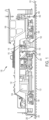
- FIG. 1 shows a tamping vehicle 100 that includes a frame assembly 102, a propulsion device 104, a tamping device 106, and a cabin 108.
- Frame assembly 102 includes a plurality of rigid frame members and a plurality of wheels 109 that are configured to travel on the pair of rails 101.
- Tamping vehicle 100 travels across a pair of rails 101, disposed over a series of rail ties 103.
- the rails 101 and series of ties 103 are disposed over a bed of ballast.
- the propulsion system 104 is configured to move tamping vehicle 100.
- the tamping device 106 is configured to tamp rail ties 103. While the tamping vehicle 100 depicted in Figure 1 contemplates a human operator for operating the vehicle, it is to be appreciated that, in some embodiments, the tamping vehicle may be operated as a drone vehicle, i.e., with no human operator onboard the vehicle during operation.
- the tamping device 106 may include multiple workheads. In the side view of Figure 1 , one workhead can be viewed while another workhead is also included at an opposite side corresponding with the other rail. Any number of workheads (2, 4, etc) may be included.
- the tamping device 106 includes paddles 110 that are lowered into the ballast. The paddles 110 are vibrated by vibrators. The paddles 110 may be actuated by an actuator, which may be hydraulic, to squeeze the paddles around the rail ties.
- the tamping device 106 is coupled to the frame assembly 102 via a subframe 116 and an actuator 118.
- the actuator 118 is preferably a hydraulic actuator and is operable to lower the tamping device 106 such that the paddles 110 are inserted into the ballast where the squeezing and vibration action tamps the ballast.
- the tamping vehicle 100 advances to position the tamping device 106 over a tie.
- the actuator 118 is actuated to lower the tamping device 106 to carry out the tamping of the ballast.
- the actuator 118 is actuated to raise (and in some cases stow) the tamping device 106 for travel to the next tie.
- the vehicle 100 is illustrated with three followers 200, 300 and 400.
- the follower 200 is disposed near a front of the vehicle at a location where work has not yet been performed.
- the follower 300 is disposed near the workhead (e.g., tamping device 106).
- the follower 400 is disposed near a back of the vehicle at a location where the work has been completed.
- the followers respectively include wheels 202, 302 and 402 to engage the rails 101.
- the followers 200, 300 and 400 are movably coupled to the frame 102 so that the wheels 202, 302 and 402 remain in contact with the rails.
- the rails 101 define a longitudinal axis
- the followers may be constrained in the longitudinal axis such that they have a fixed longitudinal position while having freedom to move laterally and vertically such that they maintain their position with respect to the rails.
- the followers 200, 300 and 400 may move independently of the frame 102.
- the followers 200, 300 and 400 may also be retracted vertically to disengage from the rails 101, for example, during transit to the work site.
- the frame or portions thereof may move relative to the workhead.
- the followers for example, the followers 200 and/or 400 may move with the frame.
- the longitudinal distance between the followers may change but is still known for a given measurement as the movement of the frame may be known or measured.
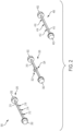
- FIG. 2 illustrates a simplified perspective view of a reference system of a rail maintenance vehicle.
- the light reference system 500 may comprise (or be attached to) frame members 210, 310 and 410.
- the frame members 210, 310, 410 may also be referred to as cross members or axles.
- the frame members 210, 310 and 410 may be respectively coupled to the wheels 202, 302 and 402, for example via bearings, such that the axles 210, 310 may maintain their orientation while the wheels spin.
- the frame members 210, 310, and 410 may be rail vehicle axles.
- the axles 210, 310, and 410 may also be axles other than main rail axle vehicles, for example, axles dedicated to the light reference system 500.
- the axles 210, 310, and 410 may be configured to be generally parallel to each other, at the same height, and in a direction perpendicular to both rail tracks.
- a plurality of light sources are disposed on each of the axles 210 and 410.
- three light emitting diodes (LEDs) 212, 214 and 216 may be disposed on the axle 210, while three LEDs 412, 414 and 416 may be disposed on the axle 410.
- LEDs may be preferable since they are small in size and produce bright light.
- the LEDs 212, 214 and 216 on the axle 210 are oriented to project light towards the axle 310.
- the LEDs 312, 314 and 316 are also oriented to project light towards the axle 310.
- the LEDs 412, 414 and 416 are on a back of the axle 410 and out of view. It will be understood that the LEDs 412, 414 and 416 may be a mirror image of the LEDs 212, 214 and 216 that are in view.
- the LEDs may be disposed to be symmetrical about the axle 310.
- the numbers, positions, and/or types of light sources disposed on the axles 210 and 410 may be flexibly configured depending on the application.
- LEDs 212, 214, and 216 are illustrated evenly spaced on the axle 210, they may also be distributed unevenly.
- a plurality of cameras are disposed on the middle axle 310 to receive light from the light sources on the axles 210 and 310.
- a first camera 322 is disposed on a first side of the axle 310 to face the LEDs 212, 214 and 216 on the axle 210.
- a second camera 324 is disposed on a second, opposite side of the axle 210 to face the LEDs 412, 414, and 416 on the axle 410.
- the cameras 322 and 324 may be digital high resolution cameras that are rigidly mounted back-to-back on opposite sides of the axle 210 to maintain their position relative to each other. Further, in some embodiments, the cameras 322 and 324 may be calibrated so that they may be "looking" exactly or about 180 degrees away from each other.
- Each camera 322 and 324 is equipped with image sensors to receive light emitted by the light sources and generate images or snapshots based on received light energy.
- the camera 322 generates an output image or frame 600 (see Figure 3A ) showing LED objects 602, 604 and 606, which correspond to LEDs 212, 214 and 216, respectively. Since relative positions of LEDs 212, 214 and 216 are fixed, positions of the LED objects 602, 604 and 606 in the captured image 600 indicate how much the vehicle axle 310 has moved with respect to the vehicle axle 210. For example, positions of the LED objects 602, 604 and 606 in the image 600 may be measured relative to a vertical axis and a lateral (or horizontal) axis shown in the image 600.
- the camera 322 may be calibrated such that when the axles 210 and 310 are aligned both vertically and laterally, the LED objects 602, 604 and 606 are disposed on the lateral axis of the image 600 at pre-determined points. Alternatively, the locations of the LED objects 602, 604 and 606 may be recorded when the axles 210 and 310 are aligned to provide a base line for comparison of the locations of the objects 602, 604 and 606 when the axles 210 and 310 are not aligned. Further, the camera 322 comprises or is coupled to a processing device, to which sensor input may be sent to analyze positions of each light source.
- the camera 324 generates an output image or frame 620 (see Figure 3B ) showing LED objects 612, 614 and 616, which correspond to LEDs 412, 414 and 416, respectively.
- vertical and lateral position of the axle 310 may be determined relative to the axles 210 and 410.
- rotations of the axle 310 (if any) about any axis may be accounted for in calculating relative positions of the axles 210, 310 and 410.
- axle rotation may be determined by comparing the locations of multiple light sources mounted on one axle to a calibrated axis of baseline position.
- the lateral rotation of the axle may be determined and it is not necessary to know or control the exact orientation at which the camera 322/324 is installed on the axle 310. Moreover, if the camera rotates during operation, the rotation can be detected and compensated using the same approach.
- each of the LEDs 212, 214 and 216 may have a different color (e.g., green, red, or blue) such that they may be distinguished by the camera 322.
- any other type of light source may be used.
- the camera 322 may individually recognize or identify each of the LEDs 212, 214 and 216.
- each light source may blink at a different frequency for the camera 322 to determine the identity of each, or each light source may have different sizes and/or shapes for identification.
- the distributed LEDs 212, 214 and 216 allow the light reference system 500 to continue to function in the event that one of the LEDs 312, 314 and 316 becomes occluded to the camera 322 for some reason (e.g., line of sight blocked by an object).
- the system 500 may continue using two of the LEDs 112, 114 and 116 though it is possible that some accuracy is lost due to the reduction of the number of light sources.
- the above discussion is similarly applicable to the camera 324 and the LEDs 412, 414 and 416, which may also be colored or otherwise distinguishable by the camera 324.
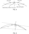
- Figure 4 is a schematic diagram illustrating an exemplary application of the light reference system 500 for vertical measurement.
- a rail vehicle e.g., including a measurement system
- three axles may include three colored LED lights at point A (which may correspond with the follower 200), three colored LED lights at point C (which may correspond with the follower 400), and back-to-back digital cameras at point B (which may correspond with the follower 300) to determine a chordal offset at point B.
- points A, B and C may represent corresponding points on the axles 210, 310 and 410.
- a line BD may perpendicularly intersect a line AC at mid-point D.
- the axle 310 may also be located at other positions.
- the camera 322 at point B may be placed in line of sight with the LED at point A, and the camera 324 (also considered to be at point B for illustration purposes) may be placed in line of sight with the LED at point C.
- Points A and C need not be in line of sight nor is a wire needed to connect points A and C.
- a chordal offset e.g ., the distance d
- the inclusive angle may be used to calculate the offset and the chordal offset does not need to be measured directly (for example, as would be required in a wire-based system).
- FIG. 5 is a schematic diagram further illustrating an exemplary application of the light reference system 500 for vertical measurement.
- each of the two cameras 322 and 324 located at point B
- Each camera may sense light at a distance, e . g ., from LEDs 212, 214, and 216 (at point A) and from LEDs 412, 414, and 416 (at point C).
- a controller may calculate angles a1 and a2 based on the location of the observed light sources in the image data information received by the cameras 322 and 324. In the case where the cameras 322 and 324 face 180 degrees apart, angle a3 equals (180-a1-a2) degrees. As an axle distance between points A and C (length l) is pre-determined and known, once angle a3 is determined, then the offset distance d can be trigonometrically calculated.
- the twist in the track can be determined by comparing the difference between the determined vertical chord offset for the first rail with the determined vertical chord offset for the second rail. Determining the offset distance d for each rail may be performed using the same approach discussed above by selecting those LEDs near that rail.
- a first plurality of LEDs on the respective axles may be disposed near the first rail and a second plurality of LEDs may be disposed near the second rail to increase the accuracy of individual rail measurements.
- Line k in Figure 5 represents a direction perpendicular to the camera direction and a rotational angle of the axle 310.
- Line k may be perpendicular to the theoretical line AC (in which case lines k and d are parallel), or alternatively be at another angle with line AC.
- Figure 5 is illustrated with a small misalignment that provides an angle between line k and line d.
- Embodiments disclosed herein permit variation in the mounting the cameras 322 and 324 on the axle 310, since the cameras 322 and 324 need not face a direction that is perfectly parallel with the line AC.
- the light reference system 500 may possess various advantages over a wire-based measuring system.
- a three-point wire-based reference system may use a wire to directly connect points A and C.
- the chordal offset BD is directly measured as a distance d between B and D.
- the embodiments disclosed herein avoid mechanical issues of wire tension, sag, and friction.
- the present disclosure also reduces the width of clear area needed through a tamping machine near the center of rail and a top of rail. Further, the disclosed light reference system may avoid upper wires above each rail, which were used for direct vertical measurement.
- the light reference system 500 may calculate the vertical positions of each rail and each axle separately in order for a tamping machine to perform its work.
- Multiple light sources e . g ., LEDs 212, 214, 216, 412, 414 and 414 on each of the axles 210 and 410 may contribute to determining the vertical position of each rail.
- the lateral measurement may be similarly accomplished by comparing the lateral position of the light sources in the image data with the calibrated axis or the baseline image data.
- the same principles can be used for both vertical and lateral measurements but scaling may be used for vertical measurement as the light sources may be located inboard of the rails.
- Spatial measurement information obtained by the light reference system may provide instructions to a machine control system, which may be part of a rail vehicle.
- the measurement information may allow the control system to move and adjust each rail of the track until the axle 310 is in the position required by control software.
- the light reference system 500 may produce necessary values for tamping system measurements, both before and after rail geometric correction, without the need for wires and the related clearance.
- additional axles may be present on a rail vehicle, and additional set of light sources and cameras may be mounted thereon for measurement.
- a third set of light sources may be disposed on a second side of the axle 410, which is opposite to the side on which LEDs 412, 414 and 416 are disposed.
- a measurement system (which may be included on a rail vehicle) may comprise a fourth axle, on which a third camera is mounted to face the third set of light sources on the second side of the third axle 410.
- a fourth camera may be mounted on an opposite side of the fourth axle.
- the measurement system may further comprise a fifth axle, on which a fourth set of light sources may be disposed to face the fourth camera.
- the third, fourth, and fifth axles may function as another independent light reference system.
- Such a setup may allow a tamping machine to measure and verify the track after the tamping machine has performed its work in correcting the geometry of the track.
- the light measurement system may be provided on other rail equipment or on a rail vehicle that does not perform track maintenance. It will also be appreciated that while the followers of the light measurement system have been illustrated in a tamping machine, one or more of the followers may be coupled to an extension or buggy disposed a distance from the tamping machine.
- FIG. 6 depicts an example computing system 1100 in accordance with some embodiments.
- the computing system 1100 can be an individual computer system 1101A or an arrangement of distributed computer systems.
- the computer system 1101A includes one or more image analysis modules 1102 that are configured to perform various tasks according to some embodiments, such as one or more methods disclosed herein. To perform these various tasks, image analysis module 1102 executes independently, or in coordination with, one or more processors 1104, which is (or are) connected to one or more storage media 1106A.
- the processor(s) 1104 is (or are) also connected to a network interface 1108 to allow the computer system 1101A to communicate over a data network 1110 with one or more additional computer systems and/or computing systems, such as 1101B, 1101C, and/or 1101D (note that computer systems 1101B, 1101C and/or 1101D may or may not share the same architecture as computer system 1101A, and may be located in different physical locations, e . g ., computer systems 1101A and 1101B may be on another maintenance vehicle, while in communication with one or more computer systems such as 1101C and/or 1101D that are located at one or more control desks at other locations.
- data network 1110 may be a private network, it may use portions of public networks, it may include remote storage and/or applications processing capabilities (e.g., cloud computing).
- a processor can include a microprocessor, microcontroller, processor module or subsystem, programmable integrated circuit, programmable gate array, or another control or computing device.
- the storage media 1106A can be implemented as one or more computer-readable or machine-readable storage media. Note that while in the example embodiment of Figure 6 storage media 1106A is depicted as within computer system 1101A, in some embodiments, storage media 1106A may be distributed within and/or across multiple internal and/or external enclosures of computing system 1101A and/or additional computing systems.
- Storage media 1106A may include one or more different forms of memory including semiconductor memory devices such as dynamic or static random access memories (DRAMs or SRAMs), erasable and programmable read-only memories (EPROMs), electrically erasable and programmable read-only memories (EEPROMs) and flash memories; magnetic disks such as fixed, floppy and removable disks; other magnetic media including tape; optical media such as compact disks (CDs) or digital video disks (DVDs), BluRays or any other type of optical media; or other types of storage devices.
- semiconductor memory devices such as dynamic or static random access memories (DRAMs or SRAMs), erasable and programmable read-only memories (EPROMs), electrically erasable and programmable read-only memories (EEPROMs) and flash memories
- magnetic disks such as fixed, floppy and removable disks; other magnetic media including tape
- optical media such as compact disks (CDs) or digital video disks (DVDs), BluRays or any other type of optical media; or other
- the instructions discussed above can be provided on one computer-readable or machine-readable storage medium, or alternatively, can be provided on multiple computer-readable or machine-readable storage media distributed in a large system having possibly plural nodes and/or non-transitory storage means.
- Such computer-readable or machine-readable storage medium or media is (are) considered to be part of an article (or article of manufacture).
- An article or article of manufacture can refer to any manufactured single component or multiple components.
- the storage medium or media can be located either in the machine running the machine-readable instructions, or located at a remote site from which machine-readable instructions can be downloaded over a network for execution.
- computer system 1101A is one example of a computing system, and that computer system 1101A may have more or fewer components than shown, may combine additional components not depicted in the example embodiment of Figure 6 , and/or computer system 1101A may have a different configuration or arrangement of the components depicted in Figure 6 .
- the various components shown in Figure 6 may be implemented in hardware, software, or a combination of both, hardware and software, including one or more signal processing and/or application specific integrated circuits.
- computing system 1100 includes computing systems with keyboards, mice, touch screens, displays, etc.
- Some computing systems in use in computing system 2100 may be desktop workstations, laptops, tablet computers, smartphones, server computers, etc.
- steps in the processing methods described herein may be implemented by running one or more functional modules in information processing apparatus such as general purpose processors, graphics processing units or application specific chips, such as ASICs, FPGAs, PLDs, or other appropriate devices.
- functional modules such as general purpose processors, graphics processing units or application specific chips, such as ASICs, FPGAs, PLDs, or other appropriate devices.
Landscapes
- Engineering & Computer Science (AREA)
- Multimedia (AREA)
- Signal Processing (AREA)
- Architecture (AREA)
- Civil Engineering (AREA)
- Structural Engineering (AREA)
- General Physics & Mathematics (AREA)
- Theoretical Computer Science (AREA)
- Physics & Mathematics (AREA)
- Computer Vision & Pattern Recognition (AREA)
- Quality & Reliability (AREA)
- Length Measuring Devices By Optical Means (AREA)
- Machines For Laying And Maintaining Railways (AREA)
Description
- The present disclosure relates to a light reference system for measurement use with rail vehicles such as track correction equipment.
- Railroads are typically constructed to include a pair of elongated, substantially parallel rails, which are coupled to a plurality of laterally extending ties. The ties are disposed on a ballast bed of hard particulate material such as gravel. Over time, normal wear and tear on the railroad may cause the rails to deviate from a desired geometric orientation.
- Rail maintenance processes for addressing such concerns may include lifting rail panel with mechanical clamps, aligning the track by shifting it to a calculated position, and then tamping the ballast under each tie to hold the track in place. This work sequence may be repeated at each tie during the course of the correction process.
- Conventional rail correction equipment includes a buggy vehicle tethered to a front end of a maintenance machine. The buggy vehicle may be a first reference point, while points near the workheads and the rear of the machine on corrected track provide additional reference points. The reference points are interconnected with steel wires that are tensioned between the first reference point (buggy vehicle) and the reference point at the corrected track. The vertical height between the tensioned wire and the reference point near the workheads is measured to calculate the track adjustment needed at that point. This approach is cumbersome requiring the tensioning of wires, and is subject to various mechanical issues such as wire tension, sag, and friction as well as the safety concern of having long tensioned wires in the work area. Therefore, an improved reference system is desired.
US4155176 describes a process and a device for measuring and registering the geometric state of a track in the course of alignment of the track with an aligning machine. The distance between a point on the already aligned track and a straight line defined by two points, one of which is on the already aligned track and one of which is on the part of the track to be aligned, is measured, and the value is registered after each alignment operation. - The present invention relates to a system for use with a rail vehicle as set out in claim 1, and to a method as set out in claim 11.
- The system may comprise a rail maintenance vehicle that includes a frame coupled to wheels that travel along rails wherein the first, second and third rail followers are movably coupled to the frame.
- Reference is now made to the following descriptions taken in conjunction with the accompanying drawings.
-
Figure 1 is a side view of an exemplary rail maintenance vehicle. -
Figure 2 is a simplified perspective view of a reference system of a rail maintenance vehicle. -
Figure 3A is an exemplary image captured with a camera of a reference system. -
Figure 3B is an exemplary image captured with a camera of a reference system. -
Figure 4 is a schematic diagram illustrating an exemplary application of a light reference system for vertical measurement. -
Figure 5 is a schematic diagram illustrating an exemplary application of a light reference system for vertical measurement. -
Figure 6 illustrates an exemplary computing system in accordance with an embodiment. - Various embodiments of are described according to the present disclosure. For example, although the present disclosure mainly uses rail vehicles and measurement systems as an example application, the disclosed principles may be applied to any machine or system that uses a multiple point (e.g., three point) reference system.
- In an embodiment, a light reference system is used as part of a measurement system, which may operate alone, or be attached to or deployed on a rail vehicle. The measurement system comprises first, second, and third axles. A first plurality of light sources are disposed on the first axle to face one side of the second axle. A second plurality of light sources are disposed on the third axle to face an opposite side of the second axle. A first camera is mounted on the first side of the second axle to face the first plurality of light sources. Further, the first camera captures an image of the first plurality of light sources and transmits a first camera sensor input to a processing device. Similarly, a second camera is mounted on the second side of the second axle to face the second plurality of light sources. The second camera captures an image of the second plurality of light sources and transmits a second camera sensor input to the processing device. Based on the first and second camera sensor inputs, the processing device measures relative vertical and lateral positions of the first, second, and third axles. The measurement information may help the tamping machine to accurately move each rail of the track until the second axle sits in a desired position. Compared to a wire-based reference systems, the light reference system disclosed herein may avoid various mechanical issues such as wire tension, sag, and friction.
- Referring now to
Figure 1 , in an embodiment, the light reference system is employed in a tamping machine rail vehicle.Figure 1 shows atamping vehicle 100 that includes aframe assembly 102, apropulsion device 104, atamping device 106, and acabin 108.Frame assembly 102 includes a plurality of rigid frame members and a plurality ofwheels 109 that are configured to travel on the pair ofrails 101. Tampingvehicle 100 travels across a pair ofrails 101, disposed over a series ofrail ties 103. Therails 101 and series ofties 103 are disposed over a bed of ballast. Thepropulsion system 104 is configured to move tampingvehicle 100. Thetamping device 106 is configured totamp rail ties 103. While thetamping vehicle 100 depicted inFigure 1 contemplates a human operator for operating the vehicle, it is to be appreciated that, in some embodiments, the tamping vehicle may be operated as a drone vehicle, i.e., with no human operator onboard the vehicle during operation. - The
tamping device 106 may include multiple workheads. In the side view ofFigure 1 , one workhead can be viewed while another workhead is also included at an opposite side corresponding with the other rail. Any number of workheads (2, 4, etc) may be included. Thetamping device 106 includespaddles 110 that are lowered into the ballast. Thepaddles 110 are vibrated by vibrators. Thepaddles 110 may be actuated by an actuator, which may be hydraulic, to squeeze the paddles around the rail ties. Thetamping device 106 is coupled to theframe assembly 102 via asubframe 116 and anactuator 118. Theactuator 118 is preferably a hydraulic actuator and is operable to lower thetamping device 106 such that thepaddles 110 are inserted into the ballast where the squeezing and vibration action tamps the ballast. In a work cycle, thetamping vehicle 100 advances to position thetamping device 106 over a tie. Theactuator 118 is actuated to lower thetamping device 106 to carry out the tamping of the ballast. Then, theactuator 118 is actuated to raise (and in some cases stow) thetamping device 106 for travel to the next tie. - The
vehicle 100 is illustrated with threefollowers follower 200 is disposed near a front of the vehicle at a location where work has not yet been performed. Thefollower 300 is disposed near the workhead (e.g., tamping device 106). Thefollower 400 is disposed near a back of the vehicle at a location where the work has been completed. - The followers respectively include
wheels rails 101. Thefollowers frame 102 so that thewheels rails 101 define a longitudinal axis, then the followers may be constrained in the longitudinal axis such that they have a fixed longitudinal position while having freedom to move laterally and vertically such that they maintain their position with respect to the rails. In this respect, thefollowers frame 102. Thefollowers rails 101, for example, during transit to the work site. In some embodiments, the frame or portions thereof may move relative to the workhead. In such an embodiment, the followers, for example, thefollowers 200 and/or 400 may move with the frame. Thus, the longitudinal distance between the followers may change but is still known for a given measurement as the movement of the frame may be known or measured. -
Figure 2 illustrates a simplified perspective view of a reference system of a rail maintenance vehicle. Thelight reference system 500 may comprise (or be attached to)frame members frame members frame members wheels axles - The
frame members axles light reference system 500. On straight, flat rail tracks, theaxles - A plurality of light sources are disposed on each of the
axles axle 210, while threeLEDs axle 410. LEDs may be preferable since they are small in size and produce bright light. TheLEDs axle 210 are oriented to project light towards theaxle 310. The LEDs 312, 314 and 316 are also oriented to project light towards theaxle 310. In the perspective view ofFigure 2 , theLEDs axle 410 and out of view. It will be understood that theLEDs LEDs - The LEDs may be disposed to be symmetrical about the
axle 310. However, it should be understood that the numbers, positions, and/or types of light sources disposed on theaxles LEDs axle 210, they may also be distributed unevenly. - To provide a three point reference setup, a plurality of cameras are disposed on the
middle axle 310 to receive light from the light sources on theaxles first camera 322 is disposed on a first side of theaxle 310 to face theLEDs axle 210. Asecond camera 324 is disposed on a second, opposite side of theaxle 210 to face theLEDs axle 410. Thecameras axle 210 to maintain their position relative to each other. Further, in some embodiments, thecameras - Each
camera camera 322 generates an output image or frame 600 (seeFigure 3A ) showingLED objects LEDs LEDs image 600 indicate how much thevehicle axle 310 has moved with respect to thevehicle axle 210. For example, positions of the LED objects 602, 604 and 606 in theimage 600 may be measured relative to a vertical axis and a lateral (or horizontal) axis shown in theimage 600. Thecamera 322 may be calibrated such that when theaxles image 600 at pre-determined points. Alternatively, the locations of the LED objects 602, 604 and 606 may be recorded when theaxles objects axles camera 322 comprises or is coupled to a processing device, to which sensor input may be sent to analyze positions of each light source. - Similarly, the
camera 324 generates an output image or frame 620 (seeFigure 3B ) showingLED objects LEDs axle 310 may be determined relative to theaxles axle 310, rotations of the axle 310 (if any) about any axis may be accounted for in calculating relative positions of theaxles camera 322/324 is installed on theaxle 310. Moreover, if the camera rotates during operation, the rotation can be detected and compensated using the same approach. - In an embodiment, each of the
LEDs camera 322. Alternatively, any other type of light source may be used. Preferably, thecamera 322 may individually recognize or identify each of theLEDs camera 322 to determine the identity of each, or each light source may have different sizes and/or shapes for identification. Further, the distributedLEDs light reference system 500 to continue to function in the event that one of the LEDs 312, 314 and 316 becomes occluded to thecamera 322 for some reason (e.g., line of sight blocked by an object). For example, thesystem 500 may continue using two of theLEDs 112, 114 and 116 though it is possible that some accuracy is lost due to the reduction of the number of light sources. The above discussion is similarly applicable to thecamera 324 and theLEDs camera 324. -
Figure 4 is a schematic diagram illustrating an exemplary application of thelight reference system 500 for vertical measurement. In an example, a rail vehicle (e.g., including a measurement system) including three axles may include three colored LED lights at point A (which may correspond with the follower 200), three colored LED lights at point C (which may correspond with the follower 400), and back-to-back digital cameras at point B (which may correspond with the follower 300) to determine a chordal offset at point B. - To the extent that each LED on an axle may have a different vertical position, points A, B and C may represent corresponding points on the
axles axle 310 sits at a mid-point between theaxles axle 310 may also be located at other positions. - As shown in
Figure 4 , thecamera 322 at point B may be placed in line of sight with the LED at point A, and the camera 324 (also considered to be at point B for illustration purposes) may be placed in line of sight with the LED at point C. Points A and C need not be in line of sight nor is a wire needed to connect points A and C. In an embodiment, by determining an inclusive angle between a first line AB and a second line CB, a chordal offset (e.g., the distance d) representing the length of line BD may be determined. The inclusive angle may be used to calculate the offset and the chordal offset does not need to be measured directly (for example, as would be required in a wire-based system). -
Figure 5 is a schematic diagram further illustrating an exemplary application of thelight reference system 500 for vertical measurement. As discussed above, each of the twocameras 322 and 324 (located at point B) may face opposite directions along a line perpendicular to theaxle 310 upon which thecameras cameras LEDs LEDs cameras cameras - With the offset distance d determined for each rail, the twist in the track can be determined by comparing the difference between the determined vertical chord offset for the first rail with the determined vertical chord offset for the second rail. Determining the offset distance d for each rail may be performed using the same approach discussed above by selecting those LEDs near that rail. In an embodiment, a first plurality of LEDs on the respective axles may be disposed near the first rail and a second plurality of LEDs may be disposed near the second rail to increase the accuracy of individual rail measurements.
- The
cameras Figure 5 represents a direction perpendicular to the camera direction and a rotational angle of theaxle 310. Line k may be perpendicular to the theoretical line AC (in which case lines k and d are parallel), or alternatively be at another angle with line AC.Figure 5 is illustrated with a small misalignment that provides an angle between line k and line d. Embodiments disclosed herein permit variation in the mounting thecameras axle 310, since thecameras - The
light reference system 500 may possess various advantages over a wire-based measuring system. A three-point wire-based reference system may use a wire to directly connect points A and C. The chordal offset BD is directly measured as a distance d between B and D. Compared with the wire-based measuring system, the embodiments disclosed herein avoid mechanical issues of wire tension, sag, and friction. The present disclosure also reduces the width of clear area needed through a tamping machine near the center of rail and a top of rail. Further, the disclosed light reference system may avoid upper wires above each rail, which were used for direct vertical measurement. - According to some aspects disclosed herein, the
light reference system 500 may calculate the vertical positions of each rail and each axle separately in order for a tamping machine to perform its work. Multiple light sources (e.g.,LEDs axles - Based on the principle of vertical measurement shown in
Figure 4 , one of ordinary skill in the art would understand the lateral measurement may be similarly accomplished by comparing the lateral position of the light sources in the image data with the calibrated axis or the baseline image data. The same principles can be used for both vertical and lateral measurements but scaling may be used for vertical measurement as the light sources may be located inboard of the rails. - Spatial measurement information obtained by the light reference system may provide instructions to a machine control system, which may be part of a rail vehicle. The measurement information may allow the control system to move and adjust each rail of the track until the
axle 310 is in the position required by control software. Thelight reference system 500 may produce necessary values for tamping system measurements, both before and after rail geometric correction, without the need for wires and the related clearance. - It should be understood that additional axles may be present on a rail vehicle, and additional set of light sources and cameras may be mounted thereon for measurement. For example, a third set of light sources may be disposed on a second side of the
axle 410, which is opposite to the side on whichLEDs third axle 410. Moreover, a fourth camera may be mounted on an opposite side of the fourth axle. The measurement system may further comprise a fifth axle, on which a fourth set of light sources may be disposed to face the fourth camera. The third, fourth, and fifth axles may function as another independent light reference system. Such a setup may allow a tamping machine to measure and verify the track after the tamping machine has performed its work in correcting the geometry of the track. - It will be appreciated that the light measurement system may be provided on other rail equipment or on a rail vehicle that does not perform track maintenance. It will also be appreciated that while the followers of the light measurement system have been illustrated in a tamping machine, one or more of the followers may be coupled to an extension or buggy disposed a distance from the tamping machine.
-
Figure 6 depicts anexample computing system 1100 in accordance with some embodiments. Thecomputing system 1100 can be anindividual computer system 1101A or an arrangement of distributed computer systems. Thecomputer system 1101A includes one or moreimage analysis modules 1102 that are configured to perform various tasks according to some embodiments, such as one or more methods disclosed herein. To perform these various tasks,image analysis module 1102 executes independently, or in coordination with, one ormore processors 1104, which is (or are) connected to one or more storage media 1106A. The processor(s) 1104 is (or are) also connected to anetwork interface 1108 to allow thecomputer system 1101A to communicate over adata network 1110 with one or more additional computer systems and/or computing systems, such as 1101B, 1101C, and/or 1101D (note thatcomputer systems computer system 1101A, and may be located in different physical locations, e.g.,computer systems data network 1110 may be a private network, it may use portions of public networks, it may include remote storage and/or applications processing capabilities (e.g., cloud computing). - A processor can include a microprocessor, microcontroller, processor module or subsystem, programmable integrated circuit, programmable gate array, or another control or computing device.
- The storage media 1106A can be implemented as one or more computer-readable or machine-readable storage media. Note that while in the example embodiment of
Figure 6 storage media 1106A is depicted as withincomputer system 1101A, in some embodiments, storage media 1106A may be distributed within and/or across multiple internal and/or external enclosures ofcomputing system 1101A and/or additional computing systems. Storage media 1106A may include one or more different forms of memory including semiconductor memory devices such as dynamic or static random access memories (DRAMs or SRAMs), erasable and programmable read-only memories (EPROMs), electrically erasable and programmable read-only memories (EEPROMs) and flash memories; magnetic disks such as fixed, floppy and removable disks; other magnetic media including tape; optical media such as compact disks (CDs) or digital video disks (DVDs), BluRays or any other type of optical media; or other types of storage devices. "Non-transitory" computer readable medium refers to the medium itself (i.e., tangible, not a signal) and not data storage persistency (e.g., RAM vs. ROM). - Note that the instructions discussed above can be provided on one computer-readable or machine-readable storage medium, or alternatively, can be provided on multiple computer-readable or machine-readable storage media distributed in a large system having possibly plural nodes and/or non-transitory storage means. Such computer-readable or machine-readable storage medium or media is (are) considered to be part of an article (or article of manufacture). An article or article of manufacture can refer to any manufactured single component or multiple components. The storage medium or media can be located either in the machine running the machine-readable instructions, or located at a remote site from which machine-readable instructions can be downloaded over a network for execution.
- It should be appreciated that
computer system 1101A is one example of a computing system, and thatcomputer system 1101A may have more or fewer components than shown, may combine additional components not depicted in the example embodiment ofFigure 6 , and/orcomputer system 1101A may have a different configuration or arrangement of the components depicted inFigure 6 . The various components shown inFigure 6 may be implemented in hardware, software, or a combination of both, hardware and software, including one or more signal processing and/or application specific integrated circuits. - It should also be appreciated that while no user input/output peripherals are illustrated with respect to
computer systems computing system 1100 include computing systems with keyboards, mice, touch screens, displays, etc. Some computing systems in use in computing system 2100 may be desktop workstations, laptops, tablet computers, smartphones, server computers, etc. - Further, the steps in the processing methods described herein may be implemented by running one or more functional modules in information processing apparatus such as general purpose processors, graphics processing units or application specific chips, such as ASICs, FPGAs, PLDs, or other appropriate devices. These modules, combinations of these modules, and/or their combination with general hardware are included within the scope of protection of the disclosure.
- While various embodiments in accordance with the disclosed principles have been described above, it should be understood that they have been presented by way of example only, and are not limiting. Thus, the breadth and scope of the invention(s) should not be limited by any of the above-described exemplary embodiments, but should be defined only in accordance with the claims.
Claims (15)
- A light reference system (500) for use with a rail vehicle (100) comprising:a first rail follower (200), a second rail follower (300) and a third rail follower (400) respectively couplable to a rail vehicle (100), the second rail follower (300) being disposed between the first and third rail followers (200, 400);a plurality of first light sources (212, 214, 216) disposed on the first rail follower (200) and configured to emit light towards the second rail follower (300);a plurality of second light sources (412, 414, 416) disposed on the third rail follower (400) and configured to emit light towards the second rail follower (300);a first camera (322) disposed on the second rail follower (300), the first camera having image sensors configured to receive the light emitted by the plurality of first light sources and generate a first image (600) based on the light received from the plurality of first light sources (212, 214, 216), the first image (600) showing a plurality of first light source objects (602, 604, 606) corresponding to the plurality of first light sources (212, 214, 216);a second camera (324) disposed on the second rail follower (300), the second camera having image sensors configured to receive the light emitted by the plurality of second light sources (412, 414, 416) and generate a second image (620) based on the light received from the plurality of second light sources, the second image (620) showing a plurality of second light source objects (612, 614, 616) corresponding to the plurality of second light sources (412, 414, 416); anda processing device (1104) configured to:receive the first image (600) from the first camera (322), and receive the second image (620) from the second camera (324);perform a measurement, based on the positions of the plurality of first light source objects (602, 604, 606) and plurality of second light source objects (612, 614, 616) shown in the first image (600) and second image (620), to determine a vertical and lateral position of the second rail follower with respect to at least one of the first rail follower and third rail follower; anddetermine a lateral chord offset, a vertical chord offset, and a twist in a pair of rails (101).
- A rail maintenance vehicle (100) comprising:the light reference system (500) of claim 1; anda frame (102) coupled to vehicle wheels (109) that travel along the rails (101); andwherein the first, second and third rail followers (200, 300, 400) are movably coupled to the frame (102).
- The system of claim 1,
wherein the plurality of first light sources includes a plurality of LEDs (212, 214, 216). - The system of claim 3, wherein each of the plurality of LEDs is a different color.
- The system of claim 1,
wherein the first camera (322) and the second camera (324) are oriented in different directions. - The system of claim 5, wherein the first camera is oriented in a direction 180 degrees from a direction in which the second camera is oriented.
- The system of claim 1, wherein:
the first camera (322) is coupled to a first side of the second rail follower (300), and the second camera (324) is coupled to a second, opposing side of the second rail follower (324). - The system of claim 1,
wherein the processing device (1104) is configured to determine a chordal length between the second rail follower and a chord between the first rail follower and the third rail follower. - The rail maintenance vehicle (100) of claim 2, wherein each of the first rail follower (200), second rail follower (300) and third rail follower (400), respectively, couple to the rails (101) by follower wheels (202, 302, 402).
- The rail maintenance vehicle (100) of claim 2, wherein the first rail follower (200) is disposed proximal a first end of the frame (102), the second rail follower (300) is disposed proximal a workhead (106) coupled to the frame, and the third rail follower (400) is disposed proximal a second end of the frame (102).
- A method for determining a chordal offset of an axle of a rail maintenance vehicle (100) according to claim 2, comprising:emitting a plurality of light signals from a first axle (210) of the rail vehicle towards a second axle (310) of the rail vehicle;emitting a plurality of light signals from a third axle (410) of the rail vehicle towards the second axle (310);generating a first image (600) of the plurality of light signals emitted from the first axle using image sensors of a first camera (322) coupled to the second axle, the first image (600) showing a plurality of first light source objects corresponding to the plurality of light signals emitted from the first axle (210);generating a second image (620) of the plurality of light signals emitted from the third axle using image sensors of a second camera coupled to the second axle, the second image (620) showing a plurality of second light source objects corresponding to the plurality of light signals emitted from the second axle (310);receiving, by a processor (1104), the first and second image; anddetermining, using the processor (1104), a chordal offset between the second axle and a chord between the first axle and the third axle based on the positions of the light source objects shown in the first image and the second image.
- The method of claim 11, wherein determining includes determining an angle between a plane perpendicular to the second axle and a chord between the second axle and the first axle, and optionally wherein determining further includes determine the chordal offset based on the determined angle and a predetermined distance between the first and third axles.
- The method of claim 11, wherein emitting the plurality of light signals from the first axle (210) includes emitting light signals from a plurality of LEDs coupled to the first axle and determining includes determining a lateral rotation of the first axle relative to the second axle (310).
- The method of claim 11, wherein the first camera (322) is coupled to a first side of the second axle (310), and the second camera (324) is coupled to a second, opposing side of the second axle (310).
- The method of claim 11, further comprising determining at least one of a lateral chordal offset and a twist in a pair of rails (101) based on the first image (600) and the second image (620) of the first and second cameras.
Applications Claiming Priority (2)
| Application Number | Priority Date | Filing Date | Title |
|---|---|---|---|
| US201562237137P | 2015-10-05 | 2015-10-05 | |
| PCT/US2016/055493 WO2017062452A1 (en) | 2015-10-05 | 2016-10-05 | Light reference system |
Publications (4)
| Publication Number | Publication Date |
|---|---|
| EP3359735A1 EP3359735A1 (en) | 2018-08-15 |
| EP3359735A4 EP3359735A4 (en) | 2019-06-05 |
| EP3359735B1 true EP3359735B1 (en) | 2024-02-07 |
| EP3359735C0 EP3359735C0 (en) | 2024-02-07 |
Family
ID=58446649
Family Applications (1)
| Application Number | Title | Priority Date | Filing Date |
|---|---|---|---|
| EP16854212.4A Active EP3359735B1 (en) | 2015-10-05 | 2016-10-05 | Light reference system |
Country Status (7)
| Country | Link |
|---|---|
| US (1) | US10011958B2 (en) |
| EP (1) | EP3359735B1 (en) |
| AU (2) | AU2016333899A1 (en) |
| BR (1) | BR112018006957B1 (en) |
| CA (1) | CA3000848C (en) |
| MX (1) | MX372648B (en) |
| WO (1) | WO2017062452A1 (en) |
Families Citing this family (3)
| Publication number | Priority date | Publication date | Assignee | Title |
|---|---|---|---|---|
| US10584448B1 (en) * | 2017-03-17 | 2020-03-10 | David Ralph Ward | Continuous serpentine concrete beamway forming system and a method for creating a hollow continuous serpentine concrete beamway |
| AT522455B1 (en) * | 2019-05-23 | 2020-11-15 | Plasser & Theurer Export Von Bahnbaumaschinen Gmbh | Track construction machine and method for tamping a track |
| CN118563626B (en) * | 2024-07-30 | 2024-10-11 | 四川顶圣工程项目管理有限公司 | Fine management system for road engineering construction pavement quality |
Family Cites Families (11)
| Publication number | Priority date | Publication date | Assignee | Title |
|---|---|---|---|---|
| CH591597A5 (en) * | 1975-11-07 | 1977-09-30 | Matisa Materiel Ind Sa | |
| CA2102140C (en) * | 1993-11-01 | 1999-02-02 | Grigory Izbinsky | Wayside monitoring of the angle-of-attack of railway vehicle wheelsets |
| US5583797A (en) * | 1994-11-03 | 1996-12-10 | Ford Motor Company | Method and apparatus for wheel alignment audit |
| US6473978B1 (en) * | 1998-06-16 | 2002-11-05 | Schenck Pegasus Corporation | Wheel alignment assembly and method |
| US6634112B2 (en) * | 2001-03-12 | 2003-10-21 | Ensco, Inc. | Method and apparatus for track geometry measurement |
| US6768551B2 (en) * | 2001-10-17 | 2004-07-27 | International Electronic Machines Corp. | Contactless wheel measurement system and method |
| US8958079B2 (en) | 2004-06-30 | 2015-02-17 | Georgetown Rail Equipment Company | System and method for inspecting railroad ties |
| CN101982609B (en) | 2010-09-19 | 2013-03-20 | 北京凌云光视数字图像技术有限公司 | Tamping wagon photoelectric measurement system and method |
| US8781655B2 (en) * | 2011-10-18 | 2014-07-15 | Herzog Railroad Services, Inc. | Automated track surveying and ballast replacement |
| US8615110B2 (en) * | 2012-03-01 | 2013-12-24 | Herzog Railroad Services, Inc. | Automated track surveying and ditching |
| EP2960371B1 (en) * | 2014-06-27 | 2017-08-09 | HP3 Real GmbH | Device for measuring tracks |
-
2016
- 2016-10-05 CA CA3000848A patent/CA3000848C/en active Active
- 2016-10-05 EP EP16854212.4A patent/EP3359735B1/en active Active
- 2016-10-05 AU AU2016333899A patent/AU2016333899A1/en not_active Abandoned
- 2016-10-05 US US15/286,009 patent/US10011958B2/en active Active
- 2016-10-05 WO PCT/US2016/055493 patent/WO2017062452A1/en not_active Ceased
- 2016-10-05 MX MX2018004075A patent/MX372648B/en active IP Right Grant
- 2016-10-05 BR BR112018006957-4A patent/BR112018006957B1/en active IP Right Grant
-
2022
- 2022-03-02 AU AU2022201424A patent/AU2022201424B2/en active Active
Also Published As
| Publication number | Publication date |
|---|---|
| CA3000848C (en) | 2024-01-02 |
| MX372648B (en) | 2020-06-19 |
| AU2022201424B2 (en) | 2024-06-20 |
| EP3359735A4 (en) | 2019-06-05 |
| EP3359735A1 (en) | 2018-08-15 |
| BR112018006957A2 (en) | 2018-10-16 |
| CA3000848A1 (en) | 2017-04-13 |
| WO2017062452A1 (en) | 2017-04-13 |
| MX2018004075A (en) | 2019-04-01 |
| AU2016333899A1 (en) | 2018-04-26 |
| BR112018006957B1 (en) | 2022-11-01 |
| AU2022201424A1 (en) | 2022-03-24 |
| US10011958B2 (en) | 2018-07-03 |
| EP3359735C0 (en) | 2024-02-07 |
| US20170096783A1 (en) | 2017-04-06 |
Similar Documents
| Publication | Publication Date | Title |
|---|---|---|
| AU2022201424B2 (en) | Light reference system | |
| US11912317B2 (en) | Rail vehicle and method for surveying a track section | |
| US10589763B2 (en) | Method and measuring system for registering a fixed point adjacent a track | |
| JP5946272B2 (en) | Railway rail displacement detector | |
| BR102017002219B1 (en) | SYSTEM AND METHOD FOR MONITORING RAILWAY WHEELS | |
| KR102669397B1 (en) | System and method for calibrating an image capturing module | |
| US9518845B2 (en) | Device for surveying tracks | |
| CN105393080A (en) | Trolley wire measurement device and trolley wire measurement method | |
| TWI705230B (en) | Vehicle size measuring device and vehicle size measuring method | |
| CN107703149A (en) | A kind of railway rail clip abnormality detection system based on binocular vision and laser speckle | |
| CN107150953A (en) | A kind of crane direction Precise Position System and method based on machine vision | |
| KR102019047B1 (en) | Apparatus and method for estimating vehicle speed within moving picture images | |
| CN102749061A (en) | Steel rail abrasion measuring method based on dynamic template | |
| JP2017015423A (en) | Roadbed shape measurement device | |
| US20170018071A1 (en) | Method and system for imaging a lumber board, method of calibrating an imaging system and calibration implement therefore | |
| CN103481911A (en) | Rim tread image collecting system and train wheel anomaly detection system | |
| CN105271006A (en) | Rubber-tyred gantry crane walking positioning, correcting and container truck alignment anti-lifting method | |
| JP4260148B2 (en) | Inspection vehicle for railway equipment | |
| CN106183895B (en) | A kind of single track contact line Abrasion detecting device and method | |
| WO2019093185A1 (en) | Track inspecting device | |
| US12103786B2 (en) | Conveyance system, control device, and control method | |
| JP6476945B2 (en) | Image processing device | |
| KR101563999B1 (en) | Method and System for measuring the state of Tire width and thickness | |
| JP2015060558A (en) | Building limit display method and apparatus | |
| CN108317997A (en) | Vibration detection system for rail vehicles in tunnels based on video analysis |
Legal Events
| Date | Code | Title | Description |
|---|---|---|---|
| STAA | Information on the status of an ep patent application or granted ep patent |
Free format text: STATUS: THE INTERNATIONAL PUBLICATION HAS BEEN MADE |
|
| PUAI | Public reference made under article 153(3) epc to a published international application that has entered the european phase |
Free format text: ORIGINAL CODE: 0009012 |
|
| STAA | Information on the status of an ep patent application or granted ep patent |
Free format text: STATUS: REQUEST FOR EXAMINATION WAS MADE |
|
| 17P | Request for examination filed |
Effective date: 20180404 |
|
| AK | Designated contracting states |
Kind code of ref document: A1 Designated state(s): AL AT BE BG CH CY CZ DE DK EE ES FI FR GB GR HR HU IE IS IT LI LT LU LV MC MK MT NL NO PL PT RO RS SE SI SK SM TR |
|
| AX | Request for extension of the european patent |
Extension state: BA ME |
|
| DAV | Request for validation of the european patent (deleted) | ||
| DAX | Request for extension of the european patent (deleted) | ||
| A4 | Supplementary search report drawn up and despatched |
Effective date: 20190508 |
|
| RIC1 | Information provided on ipc code assigned before grant |
Ipc: G06K 9/00 20060101ALI20190502BHEP Ipc: H04N 5/225 20060101ALI20190502BHEP Ipc: E01B 35/00 20060101ALI20190502BHEP Ipc: E01B 27/12 20060101AFI20190502BHEP Ipc: H04N 5/247 20060101ALI20190502BHEP |
|
| STAA | Information on the status of an ep patent application or granted ep patent |
Free format text: STATUS: EXAMINATION IS IN PROGRESS |
|
| 17Q | First examination report despatched |
Effective date: 20210202 |
|
| GRAP | Despatch of communication of intention to grant a patent |
Free format text: ORIGINAL CODE: EPIDOSNIGR1 |
|
| STAA | Information on the status of an ep patent application or granted ep patent |
Free format text: STATUS: GRANT OF PATENT IS INTENDED |
|
| RIC1 | Information provided on ipc code assigned before grant |
Ipc: E01B 35/10 20060101ALI20230718BHEP Ipc: G06V 20/56 20220101ALI20230718BHEP Ipc: H04N 23/90 20230101ALI20230718BHEP Ipc: H04N 23/56 20230101ALI20230718BHEP Ipc: E01B 35/00 20060101ALI20230718BHEP Ipc: E01B 27/12 20060101AFI20230718BHEP |
|
| INTG | Intention to grant announced |
Effective date: 20230822 |
|
| GRAS | Grant fee paid |
Free format text: ORIGINAL CODE: EPIDOSNIGR3 |
|
| GRAA | (expected) grant |
Free format text: ORIGINAL CODE: 0009210 |
|
| STAA | Information on the status of an ep patent application or granted ep patent |
Free format text: STATUS: THE PATENT HAS BEEN GRANTED |
|
| AK | Designated contracting states |
Kind code of ref document: B1 Designated state(s): AL AT BE BG CH CY CZ DE DK EE ES FI FR GB GR HR HU IE IS IT LI LT LU LV MC MK MT NL NO PL PT RO RS SE SI SK SM TR |
|
| REG | Reference to a national code |
Ref country code: GB Ref legal event code: FG4D |
|
| REG | Reference to a national code |
Ref country code: CH Ref legal event code: EP |
|
| REG | Reference to a national code |
Ref country code: IE Ref legal event code: FG4D |
|
| REG | Reference to a national code |
Ref country code: DE Ref legal event code: R096 Ref document number: 602016085696 Country of ref document: DE |
|
| U01 | Request for unitary effect filed |
Effective date: 20240207 |
|
| U07 | Unitary effect registered |
Designated state(s): AT BE BG DE DK EE FI FR IT LT LU LV MT NL PT SE SI Effective date: 20240212 |
|
| PG25 | Lapsed in a contracting state [announced via postgrant information from national office to epo] |
Ref country code: IS Free format text: LAPSE BECAUSE OF FAILURE TO SUBMIT A TRANSLATION OF THE DESCRIPTION OR TO PAY THE FEE WITHIN THE PRESCRIBED TIME-LIMIT Effective date: 20240607 |
|
| PG25 | Lapsed in a contracting state [announced via postgrant information from national office to epo] |
Ref country code: GR Free format text: LAPSE BECAUSE OF FAILURE TO SUBMIT A TRANSLATION OF THE DESCRIPTION OR TO PAY THE FEE WITHIN THE PRESCRIBED TIME-LIMIT Effective date: 20240508 |
|
| PG25 | Lapsed in a contracting state [announced via postgrant information from national office to epo] |
Ref country code: HR Free format text: LAPSE BECAUSE OF FAILURE TO SUBMIT A TRANSLATION OF THE DESCRIPTION OR TO PAY THE FEE WITHIN THE PRESCRIBED TIME-LIMIT Effective date: 20240207 Ref country code: RS Free format text: LAPSE BECAUSE OF FAILURE TO SUBMIT A TRANSLATION OF THE DESCRIPTION OR TO PAY THE FEE WITHIN THE PRESCRIBED TIME-LIMIT Effective date: 20240507 |
|
| PG25 | Lapsed in a contracting state [announced via postgrant information from national office to epo] |
Ref country code: ES Free format text: LAPSE BECAUSE OF FAILURE TO SUBMIT A TRANSLATION OF THE DESCRIPTION OR TO PAY THE FEE WITHIN THE PRESCRIBED TIME-LIMIT Effective date: 20240207 |
|
| PG25 | Lapsed in a contracting state [announced via postgrant information from national office to epo] |
Ref country code: RS Free format text: LAPSE BECAUSE OF FAILURE TO SUBMIT A TRANSLATION OF THE DESCRIPTION OR TO PAY THE FEE WITHIN THE PRESCRIBED TIME-LIMIT Effective date: 20240507 Ref country code: NO Free format text: LAPSE BECAUSE OF FAILURE TO SUBMIT A TRANSLATION OF THE DESCRIPTION OR TO PAY THE FEE WITHIN THE PRESCRIBED TIME-LIMIT Effective date: 20240507 Ref country code: IS Free format text: LAPSE BECAUSE OF FAILURE TO SUBMIT A TRANSLATION OF THE DESCRIPTION OR TO PAY THE FEE WITHIN THE PRESCRIBED TIME-LIMIT Effective date: 20240607 Ref country code: HR Free format text: LAPSE BECAUSE OF FAILURE TO SUBMIT A TRANSLATION OF THE DESCRIPTION OR TO PAY THE FEE WITHIN THE PRESCRIBED TIME-LIMIT Effective date: 20240207 Ref country code: GR Free format text: LAPSE BECAUSE OF FAILURE TO SUBMIT A TRANSLATION OF THE DESCRIPTION OR TO PAY THE FEE WITHIN THE PRESCRIBED TIME-LIMIT Effective date: 20240508 Ref country code: ES Free format text: LAPSE BECAUSE OF FAILURE TO SUBMIT A TRANSLATION OF THE DESCRIPTION OR TO PAY THE FEE WITHIN THE PRESCRIBED TIME-LIMIT Effective date: 20240207 |
|
| PG25 | Lapsed in a contracting state [announced via postgrant information from national office to epo] |
Ref country code: PL Free format text: LAPSE BECAUSE OF FAILURE TO SUBMIT A TRANSLATION OF THE DESCRIPTION OR TO PAY THE FEE WITHIN THE PRESCRIBED TIME-LIMIT Effective date: 20240207 |
|
| PG25 | Lapsed in a contracting state [announced via postgrant information from national office to epo] |
Ref country code: PL Free format text: LAPSE BECAUSE OF FAILURE TO SUBMIT A TRANSLATION OF THE DESCRIPTION OR TO PAY THE FEE WITHIN THE PRESCRIBED TIME-LIMIT Effective date: 20240207 |
|
| PG25 | Lapsed in a contracting state [announced via postgrant information from national office to epo] |
Ref country code: SM Free format text: LAPSE BECAUSE OF FAILURE TO SUBMIT A TRANSLATION OF THE DESCRIPTION OR TO PAY THE FEE WITHIN THE PRESCRIBED TIME-LIMIT Effective date: 20240207 |
|
| PG25 | Lapsed in a contracting state [announced via postgrant information from national office to epo] |
Ref country code: CZ Free format text: LAPSE BECAUSE OF FAILURE TO SUBMIT A TRANSLATION OF THE DESCRIPTION OR TO PAY THE FEE WITHIN THE PRESCRIBED TIME-LIMIT Effective date: 20240207 |
|
| PG25 | Lapsed in a contracting state [announced via postgrant information from national office to epo] |
Ref country code: SK Free format text: LAPSE BECAUSE OF FAILURE TO SUBMIT A TRANSLATION OF THE DESCRIPTION OR TO PAY THE FEE WITHIN THE PRESCRIBED TIME-LIMIT Effective date: 20240207 |
|
| PG25 | Lapsed in a contracting state [announced via postgrant information from national office to epo] |
Ref country code: SM Free format text: LAPSE BECAUSE OF FAILURE TO SUBMIT A TRANSLATION OF THE DESCRIPTION OR TO PAY THE FEE WITHIN THE PRESCRIBED TIME-LIMIT Effective date: 20240207 Ref country code: SK Free format text: LAPSE BECAUSE OF FAILURE TO SUBMIT A TRANSLATION OF THE DESCRIPTION OR TO PAY THE FEE WITHIN THE PRESCRIBED TIME-LIMIT Effective date: 20240207 Ref country code: RO Free format text: LAPSE BECAUSE OF FAILURE TO SUBMIT A TRANSLATION OF THE DESCRIPTION OR TO PAY THE FEE WITHIN THE PRESCRIBED TIME-LIMIT Effective date: 20240207 Ref country code: CZ Free format text: LAPSE BECAUSE OF FAILURE TO SUBMIT A TRANSLATION OF THE DESCRIPTION OR TO PAY THE FEE WITHIN THE PRESCRIBED TIME-LIMIT Effective date: 20240207 |
|
| REG | Reference to a national code |
Ref country code: DE Ref legal event code: R097 Ref document number: 602016085696 Country of ref document: DE |
|
| U20 | Renewal fee for the european patent with unitary effect paid |
Year of fee payment: 9 Effective date: 20241028 |
|
| PLBE | No opposition filed within time limit |
Free format text: ORIGINAL CODE: 0009261 |
|
| STAA | Information on the status of an ep patent application or granted ep patent |
Free format text: STATUS: NO OPPOSITION FILED WITHIN TIME LIMIT |
|
| 26N | No opposition filed |
Effective date: 20241108 |
|
| REG | Reference to a national code |
Ref country code: CH Ref legal event code: PL |
|
| GBPC | Gb: european patent ceased through non-payment of renewal fee |
Effective date: 20241005 |
|
| PG25 | Lapsed in a contracting state [announced via postgrant information from national office to epo] |
Ref country code: MC Free format text: LAPSE BECAUSE OF FAILURE TO SUBMIT A TRANSLATION OF THE DESCRIPTION OR TO PAY THE FEE WITHIN THE PRESCRIBED TIME-LIMIT Effective date: 20240207 |
|
| PG25 | Lapsed in a contracting state [announced via postgrant information from national office to epo] |
Ref country code: GB Free format text: LAPSE BECAUSE OF NON-PAYMENT OF DUE FEES Effective date: 20241005 |
|
| PG25 | Lapsed in a contracting state [announced via postgrant information from national office to epo] |
Ref country code: CH Free format text: LAPSE BECAUSE OF NON-PAYMENT OF DUE FEES Effective date: 20241031 |
|
| PG25 | Lapsed in a contracting state [announced via postgrant information from national office to epo] |
Ref country code: IE Free format text: LAPSE BECAUSE OF NON-PAYMENT OF DUE FEES Effective date: 20241005 |
|
| U20 | Renewal fee for the european patent with unitary effect paid |
Year of fee payment: 10 Effective date: 20251027 |
|
| PG25 | Lapsed in a contracting state [announced via postgrant information from national office to epo] |
Ref country code: CY Free format text: LAPSE BECAUSE OF FAILURE TO SUBMIT A TRANSLATION OF THE DESCRIPTION OR TO PAY THE FEE WITHIN THE PRESCRIBED TIME-LIMIT; INVALID AB INITIO Effective date: 20161005 |
|
| PG25 | Lapsed in a contracting state [announced via postgrant information from national office to epo] |
Ref country code: HU Free format text: LAPSE BECAUSE OF FAILURE TO SUBMIT A TRANSLATION OF THE DESCRIPTION OR TO PAY THE FEE WITHIN THE PRESCRIBED TIME-LIMIT; INVALID AB INITIO Effective date: 20161005 |
|
| PG25 | Lapsed in a contracting state [announced via postgrant information from national office to epo] |
Ref country code: TR Free format text: LAPSE BECAUSE OF FAILURE TO SUBMIT A TRANSLATION OF THE DESCRIPTION OR TO PAY THE FEE WITHIN THE PRESCRIBED TIME-LIMIT Effective date: 20240207 |