EP3358858A1 - Control terminal device and device control method - Google Patents
Control terminal device and device control method Download PDFInfo
- Publication number
- EP3358858A1 EP3358858A1 EP16851359.6A EP16851359A EP3358858A1 EP 3358858 A1 EP3358858 A1 EP 3358858A1 EP 16851359 A EP16851359 A EP 16851359A EP 3358858 A1 EP3358858 A1 EP 3358858A1
- Authority
- EP
- European Patent Office
- Prior art keywords
- audio
- room
- screen
- devices
- controller
- Prior art date
- Legal status (The legal status is an assumption and is not a legal conclusion. Google has not performed a legal analysis and makes no representation as to the accuracy of the status listed.)
- Ceased
Links
Images








Classifications
-
- H—ELECTRICITY
- H04—ELECTRIC COMMUNICATION TECHNIQUE
- H04N—PICTORIAL COMMUNICATION, e.g. TELEVISION
- H04N21/00—Selective content distribution, e.g. interactive television or video on demand [VOD]
- H04N21/40—Client devices specifically adapted for the reception of or interaction with content, e.g. set-top-box [STB]; Operations thereof
- H04N21/43—Processing of content or additional data, e.g. demultiplexing additional data from a digital video stream; Elementary client operations, e.g. monitoring of home network or synchronising decoder's clock; Client middleware
- H04N21/4302—Content synchronisation processes, e.g. decoder synchronisation
- H04N21/4307—Synchronising the rendering of multiple content streams or additional data on devices, e.g. synchronisation of audio on a mobile phone with the video output on the TV screen
- H04N21/43076—Synchronising the rendering of multiple content streams or additional data on devices, e.g. synchronisation of audio on a mobile phone with the video output on the TV screen of the same content streams on multiple devices, e.g. when family members are watching the same movie on different devices
-
- H—ELECTRICITY
- H04—ELECTRIC COMMUNICATION TECHNIQUE
- H04L—TRANSMISSION OF DIGITAL INFORMATION, e.g. TELEGRAPHIC COMMUNICATION
- H04L12/00—Data switching networks
- H04L12/28—Data switching networks characterised by path configuration, e.g. LAN [Local Area Networks] or WAN [Wide Area Networks]
- H04L12/2803—Home automation networks
- H04L12/283—Processing of data at an internetworking point of a home automation network
- H04L12/2834—Switching of information between an external network and a home network
-
- H—ELECTRICITY
- H04—ELECTRIC COMMUNICATION TECHNIQUE
- H04H—BROADCAST COMMUNICATION
- H04H20/00—Arrangements for broadcast or for distribution combined with broadcast
- H04H20/53—Arrangements specially adapted for specific applications, e.g. for traffic information or for mobile receivers
- H04H20/61—Arrangements specially adapted for specific applications, e.g. for traffic information or for mobile receivers for local area broadcast, e.g. instore broadcast
- H04H20/63—Arrangements specially adapted for specific applications, e.g. for traffic information or for mobile receivers for local area broadcast, e.g. instore broadcast to plural spots in a confined site, e.g. MATV [Master Antenna Television]
-
- H—ELECTRICITY
- H04—ELECTRIC COMMUNICATION TECHNIQUE
- H04L—TRANSMISSION OF DIGITAL INFORMATION, e.g. TELEGRAPHIC COMMUNICATION
- H04L12/00—Data switching networks
- H04L12/28—Data switching networks characterised by path configuration, e.g. LAN [Local Area Networks] or WAN [Wide Area Networks]
- H04L12/2803—Home automation networks
- H04L12/2807—Exchanging configuration information on appliance services in a home automation network
- H04L12/2809—Exchanging configuration information on appliance services in a home automation network indicating that an appliance service is present in a home automation network
-
- H—ELECTRICITY
- H04—ELECTRIC COMMUNICATION TECHNIQUE
- H04L—TRANSMISSION OF DIGITAL INFORMATION, e.g. TELEGRAPHIC COMMUNICATION
- H04L12/00—Data switching networks
- H04L12/28—Data switching networks characterised by path configuration, e.g. LAN [Local Area Networks] or WAN [Wide Area Networks]
- H04L12/2803—Home automation networks
- H04L12/2807—Exchanging configuration information on appliance services in a home automation network
- H04L12/281—Exchanging configuration information on appliance services in a home automation network indicating a format for calling an appliance service function in a home automation network
-
- H—ELECTRICITY
- H04—ELECTRIC COMMUNICATION TECHNIQUE
- H04L—TRANSMISSION OF DIGITAL INFORMATION, e.g. TELEGRAPHIC COMMUNICATION
- H04L12/00—Data switching networks
- H04L12/28—Data switching networks characterised by path configuration, e.g. LAN [Local Area Networks] or WAN [Wide Area Networks]
- H04L12/2803—Home automation networks
- H04L12/2807—Exchanging configuration information on appliance services in a home automation network
- H04L12/2812—Exchanging configuration information on appliance services in a home automation network describing content present in a home automation network, e.g. audio video content
-
- H—ELECTRICITY
- H04—ELECTRIC COMMUNICATION TECHNIQUE
- H04L—TRANSMISSION OF DIGITAL INFORMATION, e.g. TELEGRAPHIC COMMUNICATION
- H04L12/00—Data switching networks
- H04L12/28—Data switching networks characterised by path configuration, e.g. LAN [Local Area Networks] or WAN [Wide Area Networks]
- H04L12/2803—Home automation networks
- H04L12/2816—Controlling appliance services of a home automation network by calling their functionalities
- H04L12/282—Controlling appliance services of a home automation network by calling their functionalities based on user interaction within the home
-
- H—ELECTRICITY
- H04—ELECTRIC COMMUNICATION TECHNIQUE
- H04N—PICTORIAL COMMUNICATION, e.g. TELEVISION
- H04N21/00—Selective content distribution, e.g. interactive television or video on demand [VOD]
- H04N21/40—Client devices specifically adapted for the reception of or interaction with content, e.g. set-top-box [STB]; Operations thereof
- H04N21/41—Structure of client; Structure of client peripherals
- H04N21/422—Input-only peripherals, i.e. input devices connected to specially adapted client devices, e.g. global positioning system [GPS]
- H04N21/42204—User interfaces specially adapted for controlling a client device through a remote control device; Remote control devices therefor
- H04N21/42206—User interfaces specially adapted for controlling a client device through a remote control device; Remote control devices therefor characterized by hardware details
- H04N21/42208—Display device provided on the remote control
-
- H—ELECTRICITY
- H04—ELECTRIC COMMUNICATION TECHNIQUE
- H04N—PICTORIAL COMMUNICATION, e.g. TELEVISION
- H04N21/00—Selective content distribution, e.g. interactive television or video on demand [VOD]
- H04N21/40—Client devices specifically adapted for the reception of or interaction with content, e.g. set-top-box [STB]; Operations thereof
- H04N21/41—Structure of client; Structure of client peripherals
- H04N21/422—Input-only peripherals, i.e. input devices connected to specially adapted client devices, e.g. global positioning system [GPS]
- H04N21/42204—User interfaces specially adapted for controlling a client device through a remote control device; Remote control devices therefor
- H04N21/42206—User interfaces specially adapted for controlling a client device through a remote control device; Remote control devices therefor characterized by hardware details
- H04N21/42224—Touch pad or touch panel provided on the remote control
-
- H—ELECTRICITY
- H04—ELECTRIC COMMUNICATION TECHNIQUE
- H04N—PICTORIAL COMMUNICATION, e.g. TELEVISION
- H04N21/00—Selective content distribution, e.g. interactive television or video on demand [VOD]
- H04N21/40—Client devices specifically adapted for the reception of or interaction with content, e.g. set-top-box [STB]; Operations thereof
- H04N21/43—Processing of content or additional data, e.g. demultiplexing additional data from a digital video stream; Elementary client operations, e.g. monitoring of home network or synchronising decoder's clock; Client middleware
- H04N21/436—Interfacing a local distribution network, e.g. communicating with another STB or one or more peripheral devices inside the home
- H04N21/43615—Interfacing a Home Network, e.g. for connecting the client to a plurality of peripherals
-
- H—ELECTRICITY
- H04—ELECTRIC COMMUNICATION TECHNIQUE
- H04N—PICTORIAL COMMUNICATION, e.g. TELEVISION
- H04N21/00—Selective content distribution, e.g. interactive television or video on demand [VOD]
- H04N21/40—Client devices specifically adapted for the reception of or interaction with content, e.g. set-top-box [STB]; Operations thereof
- H04N21/47—End-user applications
- H04N21/485—End-user interface for client configuration
- H04N21/4852—End-user interface for client configuration for modifying audio parameters, e.g. switching between mono and stereo
-
- H—ELECTRICITY
- H04—ELECTRIC COMMUNICATION TECHNIQUE
- H04N—PICTORIAL COMMUNICATION, e.g. TELEVISION
- H04N21/00—Selective content distribution, e.g. interactive television or video on demand [VOD]
- H04N21/80—Generation or processing of content or additional data by content creator independently of the distribution process; Content per se
- H04N21/81—Monomedia components thereof
- H04N21/8106—Monomedia components thereof involving special audio data, e.g. different tracks for different languages
-
- H—ELECTRICITY
- H04—ELECTRIC COMMUNICATION TECHNIQUE
- H04R—LOUDSPEAKERS, MICROPHONES, GRAMOPHONE PICK-UPS OR LIKE ACOUSTIC ELECTROMECHANICAL TRANSDUCERS; ELECTRIC HEARING AIDS; PUBLIC ADDRESS SYSTEMS
- H04R27/00—Public address systems
-
- H—ELECTRICITY
- H04—ELECTRIC COMMUNICATION TECHNIQUE
- H04L—TRANSMISSION OF DIGITAL INFORMATION, e.g. TELEGRAPHIC COMMUNICATION
- H04L12/00—Data switching networks
- H04L12/28—Data switching networks characterised by path configuration, e.g. LAN [Local Area Networks] or WAN [Wide Area Networks]
- H04L12/2803—Home automation networks
- H04L2012/284—Home automation networks characterised by the type of medium used
- H04L2012/2841—Wireless
-
- H—ELECTRICITY
- H04—ELECTRIC COMMUNICATION TECHNIQUE
- H04R—LOUDSPEAKERS, MICROPHONES, GRAMOPHONE PICK-UPS OR LIKE ACOUSTIC ELECTROMECHANICAL TRANSDUCERS; ELECTRIC HEARING AIDS; PUBLIC ADDRESS SYSTEMS
- H04R2227/00—Details of public address [PA] systems covered by H04R27/00 but not provided for in any of its subgroups
- H04R2227/005—Audio distribution systems for home, i.e. multi-room use
-
- H—ELECTRICITY
- H04—ELECTRIC COMMUNICATION TECHNIQUE
- H04R—LOUDSPEAKERS, MICROPHONES, GRAMOPHONE PICK-UPS OR LIKE ACOUSTIC ELECTROMECHANICAL TRANSDUCERS; ELECTRIC HEARING AIDS; PUBLIC ADDRESS SYSTEMS
- H04R3/00—Circuits for transducers
- H04R3/12—Circuits for transducers for distributing signals to two or more loudspeakers
Definitions
- a preferred embodiment of the present invention relates to a control terminal and a method for controlling a device, wherein the control terminal and the method group two or more devices and cause the devices to perform a synchronized operation in the group.
- an audio system in which a plurality of audio devices (playing devices) arranged in each room (area), such as a living room and a bedroom, are connected to a network (wireless network, in particular), and in which an operation such as content playing of each of the audio devices is controlled by a portable terminal device.
- a user by operating a portable terminal device, can cause one selected audio device to execute content playing or the like.
- the user by operating a portable terminal device, can also specify (select) a plurality of audio devices to perform a group setting. Then, the user can cause the audio devices that belong to a group to execute synchronous playing of the same content.
- Patent Literature 1 Japanese Unexamined Patent Application Publication No. 2013-251594
- an object of a preferred embodiment of the present invention is to allow a control terminal to more easily perform group setting, the control terminal grouping two or more devices and causing the devices to perform a synchronized operation in the group.
- a control terminal is provided with a selection portion and a control portion.
- the selection portion receives an operation to select one or more devices and receives a group setting operation of the devices.
- the control portion in case the group setting operation is performed while the devices are not selected, receives a selection of a master device in the group and a client device that synchronizes the master device, and groups these selected devices.
- the control portion in case the group setting operation is performed while one device is previously selected, sets a previously selected device as a master device, receives the selection of a client device that synchronizes the master device, and groups the selected devices.
- the group setting of devices is able to be more easily performed, the group setting causing the devices to operate synchronously.
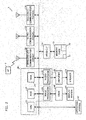
- Fig. 1 shows a diagram illustrating a configuration of an audio system.
- the audio system 10 has a plurality of audio devices 4 (4-1 to 4-6) and a multifunctional portable phone (portable terminal device) 1.
- the plurality of the audio devices 4 (4-1 to 4-6) and the portable terminal devices 1 are connected in a network 9 including a wired LAN 2 and an access point (external access point) 3.
- the portable terminal device 1 is a control terminal, and serves as a controller 1.
- Each of the audio devices 4 transmits and receives an audio signal mutually through the network 9.
- the controller 1 transmits a command message to each of the audio devices 4 through the network 9.
- Each of the audio devices 4 (hereinafter also referred to as a component device) has a wired LAN function and two wireless LAN functions. Each of the audio devices 4 is able to start an access point using one of the two wireless LAN functions.
- the access point started by each of the audio devices 4 is called an internal access point 4A.
- To the internal access point 4A one of the lower-level audio devices 4 is connected.
- the internal access point 4A usually (except the time of an initial connection to be described later) operates in a stealth mode, and the presence of the internal access point 4A is hardly known to other devices.
- the other of the wireless LAN functions serves as a slave machine of the wireless LAN, and is connected to the internal access point 4A of one of the higher-level audio devices 4 or an external access point 3.
- the access point (external access point) 3 is connected to the wired LAN 2.
- the audio device 4-1 is connected to the wired LAN 2 by a cable.
- the audio device 4-2 and the audio device 4-3 are connected to an internal access point 4A-1 of the higher-level audio device 4-1 by the wireless LAN.
- the audio device 4-4 is connected to an internal access point 4A-2 of the higher-level audio device 4-2 by the wireless LAN.
- the audio device 4-5 is connected to an internal access point 4A-3 of the higher-level audio device 4-3 by the wireless LAN.
- the audio device 4-6 is connected to the external access point 3.
- the network 9 is configured by the wired LAN 2, the external access point 3, and the wireless LAN including the internal access point 4A.
- the wired LAN 2 uses, for example, Ethernet (registered trademark: IEEE 802.3).
- the wireless LAN uses Wi-Fi (IEEE 802.11g).
- a delivery server 6 is connected from the wired LAN 2 through the gateway (not shown) and the Internet 5.
- the delivery server 6 delivers music data to the audio devices 4.
- Each of the audio devices 4 is called a root device, a node device, a leaf device, and a branch device, according to the configuration of the connection to the wired LAN 2.
- the root device is the top-level device connected to the wired LAN 2 directly (with a cable), and the audio device 4-1 is a root device in Fig. 1 .
- the root device is an audio device that has first been registered at the time of the configuration of the audio system 10, and serves as a reference point of the audio system 10.
- the root device starts the internal access point 4A to connect one of the lower-level audio devices 4 to the network and causing the one of the lower-level audio devices 4 to participate in the audio system 10.
- the music information that is reproduced by at least one of the audio devices 4 (a node device and a leaf device) that is connected below the root device is all transmitted through the root device.
- the node device is a middle-level device connected to the root device (internal access point 4A of the root device) by the wireless LAN, and the audio device 4-2 and the audio device 4-3 are node devices in Fig. 1 .
- the node device starts the internal access point 4A to connect one of the lower-level audio devices 4 to the network and cause the lower-level audio devices 4 to participate in the audio system 10.
- the music information that is reproduced by the audio devices 4 (a leaf device) that are connected to a device below the node device is all transmitted through the node device.
- the leaf device is a lower-level device connected to the node device (internal access point 4A of the node device) by the wireless LAN.
- the audio device 4-4 and the audio device 4-5 are leaf devices in Fig. 1 . It is to be noted that the leaf device does not start the internal access point 4A, but may be configured to start the internal access point 4A.
- the branch device is an audio device 4 that is connected to the external access point 3 by the wireless LAN, separately from a tree having a root device as the top and that communicates with other audio devices 4 in the audio system 10 through the wired LAN 2, and, in Fig. 1 , the audio device 4-6 is a branch device. It is to be noted that the branch device does not start the internal access point 4A, but may be configured to start the internal access point 4A.
- the root device in order to transmit a high quality audio signal, the root device is allowed to connect up to two node devices.
- each of the node devices is allowed to connect up to two leaf devices.
- the hierarchy of connection using the internal access point 4A comprises up to three hierarchy levels of a root device to a node device to a leaf device. Therefore, the tree of a wireless LAN including a root device as the top device makes it possible to connect up to seven audio devices including the root device.
- Five audio devices 4 (4-1 to 4-5) are connected to the tree illustrated in Fig. 1 .
- the number of audio devices 4 is limited to up to ten audio devices in the entire audio system 10.
- the maximum number such as the number of hierarchies of a tree and the number of lower-level devices connectable to each of the audio devices 4 is not limited to the present preferred embodiment.
- each of the audio devices 4-1 to 4-6 is arranged in a room (area) of a living room, a dining room, a bedroom, a kitchen, a room A, and a room B that are in the same building.
- each of the audio devices 4-1 to 4-6 of the audio system 10 is able to independently play separate content
- a plurality of audio devices 4-1 to 4-6 are able to be grouped, and the grouped audio devices 4-1 to 4-6 synchronously play the same content.
- the content is for example music (audio) .
- the music is music data stored in a CD, a hard disk, or the like that are included in each of the audio devices 4-1 to 4-6, and the file format of the music data is for example MP3, WAV, SoundVQ (registered trademark), WMA (registered trademark), or AAC.
- the portable phone 1 serves as an audio system controller (hereinafter referred to as a controller) 1 by starting an audio system control program 70 (see Fig. 2 ).
- the portable phone 1 (controller 1) communicates with each of the audio devices 4 that belong to the audio system 10, through the network 9.
- the controller 1 controls an audio source to be played in each of the audio devices 4-1 to 4-6 in the audio system 10 (each of the audio devices 4 plays the music, which is delivered to each of the audio devices 4, or the like, for example) or the sound volume, and the like, in an integrated manner.
- each of the audio devices 4 communicates with other audio devices 4 through the network 9, and mutually transmits and receives an audio signal.
- the controller 1 receives an operation input to set a group that performs the synchronous playing.
- the group is able to be set up per room (area) .
- the controller 1 is able to allow the audio devices 4, which are arranged in a room belonging to the group, to perform synchronous playing.
- the portable phone 1 is a multifunctional telephone that is a so-called smartphone.
- the portable phone 1 has a 3G/4G communication function which is a portable communication network, a wireless LAN (Wi-Fi) communication function, and a Bluetooth (registered trademark) communication function.
- the audio system control program 70 which is an application program, the portable phone 1 serves as a controller 1, communicates with the audio devices 4 of the audio system through the network, transmits a command message according to the operation of a user, to the audio devices 4, and controls the audio system.
- the portable phone 1, on a bus 26, has a control portion 20, an operation portion 30, a media interface 31, a Wi-Fi communication circuit 32, a 3G/4G communication circuit 33, and a Bluetooth (registered trademark) communication portion 34.
- the control portion 20 includes a CPU 21, a ROM (flash memory) 22, a RAM 23, an image processor 24, and an audio processor 25.
- a video RAM (VRAM) 40 is connected, and, to the VRAM 40, a display portion 41 is connected.
- the display portion 41 includes a liquid crystal display. On the display, a standby screen, a telephone number, and the like are displayed. When serving as the controller 1, a screen for controlling the audio devices 4 is displayed.
- an amplifier 42 including a D/A converter is connected, and to the amplifier 42 a speaker 16 is connected.
- the image processor 24 is provided with a GPU (Graphics Processing Unit) that generates various images such as a standby screen and a telephone number.
- the image processor 24 When the audio system control program 70 is started, the image processor 24 generates the image of an audio controller according to instruction of the CPU 21, and develops the image on the VRAM 40. The image developed on the VRAM 40 is displayed on the display portion 41.
- a GPU Graphics Processing Unit
- the audio processor 25 has a DSP (Digital Signal Processor) that encodes and decodes telephone call sounds.
- the audio processor 25 outputs the decoded or generated sound to the amplifier 42.
- the amplifier 42 amplifies this sound signal and outputs a resulting sound signal to the speaker 16.
- the wireless LAN communication circuit 32 performs wireless communication with the access point 3 in conformity with the IEEE 802.11g standard, and communicates with the audio devices 4 through the access point 3.
- the 3G/4G communication circuit 33 performs a voice communication and a data communication through a portable telephone communication network.
- the Bluetooth communication portion 34 communicates with other Bluetooth compatible devices and for example performs transmission and reception of an audio signal.
- the operation portion 30 includes a touch panel 310 (mainly see Fig. 11 ) that is formed on the display portion 41 and detects a touch operation and a flick operation on the touch panel 310.
- a touch panel 310 (mainly see Fig. 11 ) that is formed on the display portion 41 and detects a touch operation and a flick operation on the touch panel 310.
- the audio system control program 70 is started, on the display portion 41 a plurality of operation elements such as a setup button and a scan button are displayed.
- the operation portion 30 detects the touch operation of a user and the coordinates of the operation by the touch panel 310, and determines which operation element has been operated.
- the media interface 31 is connected to a memory card 15.
- the memory card 15 is for example a micro SD card.
- the audio system control program 70 is stored in the memory card 15 or the ROM 22. In the present preferred embodiment, the audio system control program 70 is stored in the memory card 15, as shown in Fig. 2 . It is to be noted that the audio system control program 70 may be downloaded through the 3G/4G data communication or the wireless LAN data communication or may be previously stored in the ROM 22 or the memory card 15. In addition, in the memory card 15, a storage area 71 that stores the configuration of the audio system is set.
- ROM 22 a basic program for executing a telephone call and an application program of this portable phone 1 is stored.
- the ROM 22 is a flash memory, and besides the basic program, is also capable of storing an application program that has been downloaded.
- RAM 23 a work area that is used when the CPU 21 executes the audio system control program 70 is set.
- the control portion 20, when the CPU 21 executes the audio system control program 70, functions as a selection portion, and receives the operation input to set a group that performs synchronous playing.
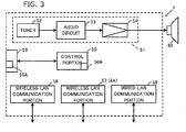
- the one of the audio devices 4 has a control portion 50, an audio processing portion 51, an operation portion 59, a wireless LAN communication portion (RF module) 56, a wireless LAN communication portion 57, and a wired LAN communication portion 58.
- the operation portion 59 has a connect button 59A in addition to a volume operation element (not shown).
- the control portion 50 includes a CPU and a memory and stores an audio system program. The control portion 50 controls the operation of the audio processing portion 51, and the wireless LAN communication portion 56, the wireless LAN communication portion 57, and the wired LAN communication portion 58 by the audio system program.
- the audio device 4 functions as a play device that plays content and also as a synchronous play controller to be a master device that controls the synchronous playing.
- the control portion 50 when the connect button 59A is pressed, executes an initial connection operation that is an operation to connect this audio device 4 to the network 9. The details of the initial connection operation will be described below.
- the wireless LAN communication portion 56 performs wireless communication by the wireless LAN standards such as IEEE 802.11g with the external access point 3 or the internal access point 4A of one of the higher-level audio devices 4. Moreover, another wireless LAN communication portion 57 is started as an access point (internal access point 4A), and relays other audio devices (audio device 4-2 or audio device 4-3, for example) to the wired LAN 2. Furthermore, the wireless LAN communication portion 57 is started as a temporary access point for initial connection at the time of initial connection, and communicates with the controller 1 (portable phone 1) . The operation at the time of initial connection will be described below.
- the wireless LAN communication portion 56 performs wireless communication by the wireless LAN standards such as IEEE 802.11g with the external access point 3 or the internal access point 4A of one of the higher-level audio devices 4. Moreover, another wireless LAN communication portion 57 is started as an access point (internal access point 4A), and relays other audio devices (audio device 4-2 or audio device 4-3, for example) to the wired
- both the wireless LAN communication portion 56 and the wireless LAN communication portion 57 may be implemented by operating one piece of hardware in a time-sharing manner.
- the wired LAN communication portion 58 has a cable connector, and performs communication by the communication standards such as IEEE 802.3 through the wired LAN 2 and the access point 3.
- the controller (portable phone) 1 is connected to the access point 3, and the control portion 50 communicates with the controller 1 through the network 9, transmits an operation state, and receives a command message.
- the SSID and password of the internal access point 4A are provided as a character string that is able to be found out from the MAC address of the wireless LAN communication portion 57.
- the MAC address is an octet expressed as an SSID and the like, and the lower three octets (model ID + serial number) are used as a password and the like. Accordingly, an audio device to newly participate in the audio system is able to find the internal access point 4A based on the SSID, that is, based on the vendor ID of the MAC address and model ID, and is able to generate a password by itself, and is able to connect to the internal access point 4A.
- the input of an SSID or a password by a user when connecting to the internal access point 4A may be omitted. It is to be noted that a method of generating an SSID of the internal access point 4A and a password is not limited to the above-described method.
- the audio processing portion 51 has a tuner 52, an audio circuit 53, and a power amplifier 54.
- the tuner 52 receives an audio signal from an FM broadcast or the Internet, and inputs the audio signal into the audio circuit 53.
- the audio circuit 53 performs a process such as equalizing or volume adjustment to an input audio signal.
- the audio circuit 53 outputs a processed audio signal to the power amplifier 54.
- the power amplifier 54 amplifies the input audio signal, and outputs an amplified audio signal to a speaker 55 that is connected externally.
- the speaker 55 emits the input audio signal as sound.
- the audio devices 4-1 to 4-6 may be different devices, the respective basic configuration of a communication function and an audio signal processing function is illustrated in Fig. 3 .
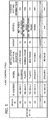
- Fig. 4 and Fig. 5 each illustrate an example of a table that manages the audio system 10.
- Fig. 4 is a system management table that manages the connection configuration of each of the audio devices 4 in the network 9.
- Fig. 5 is an audio control table that manages the operation of each of the audio devices 4 in the audio system 10.
- the system management table is used mainly by the audio device 4-1 to be a root device in order to manage network connection.
- the audio control table is used, mainly by the controller 1, to control the play of an audio source.
- the system management table is a table that stores the connection configuration of each of the audio devices 4 (a component device) and the audio system 10 that the controller 1 creates at the time of configuration of the audio system 10.
- the controller 1 updates the system management table by adding the new one of the audio devices 4.
- the system management table that has been created or added and updated is transmitted from the controller 1 to the audio device 4-1 to be a root device. Then, the system management table, during the operation of the audio system 10, is updated by the audio device 4-1 used as a root device every time the disconnection or the reconnection of any of the component devices occurs.
- the audio device 4-1 used as a root device periodically transmits all or a part of the details of the system management table as system information to each of the component devices and the controller 1. Accordingly, each of the component devices and the controller 1 are always able to store the latest system information. The detailed operation of transmission of the above system information will be described below.
- the system management table is identified by a system ID for identifying the audio system 10.
- Each of the component devices associates a device ID of each device and stores information such as the higher-level side (slave machine side) and lower-level side (internal access point side) MAC address (that is, the MAC address of each of the wireless LAN communication portions 56 and 57), the higher-level side and lower-level side IP address (that is, the IP address of each of the wireless LAN communication portions 56 and 57), the number of connection stages (the number of HOPs) from the audio device 4-1 used as a root device, the presence or absence of a start of an internal access point, or the number of lower-level devices (the number of children) connected to the internal access point 4A.
- the higher-level side and lower-level side (internal access point side) MAC address that is, the MAC address of each of the wireless LAN communication portions 56 and 57
- the higher-level side and lower-level side IP address that is, the IP address of each of the wireless LAN
- each of the component devices has an individual IP address, for the audio system 10, a multicast address is set as a multicasting group.
- Each of the component devices by transmitting an IP packet of the system information to the multicast address, is able to cause all the component devices of the audio system 10 to receive this system information packet.
- each of the component devices may transmit the system information packet to the IP address of each of the component devices by unicast, but transmitting by multicast may reduce the load of the network 9.
- the audio control table illustrated in Fig. 5 associates a device ID of each device and stores various types of setting information such as the higher-level side IP address (the IP address of the wireless LAN communication portion 56) of each of the component devices, a model, an installation location, a group, service, a volume value, and a display name.
- Each column of the audio control table and each column of the system management table are associated with each other by the device ID.
- the controller 1 creates a control screen (see Fig. 11 to Fig. 15 ) based on the details of the audio control table, and receives control of each of the component devices by a user.
- the installation location is information that specifies a room (area) in which the audio device is installed. Although a name is displayed in Fig. 5 , a room ID of a room in which a device is installed may for example be registered in the installation location.
- the information of the installation location (room ID) is set for each of the audio devices 4, for example, when the audio device is installed in a room.
- the room ID is associated with each piece of information of a room table illustrated in Fig. 6.
- Fig. 6 illustrates an example of the room table.
- information related to rooms in which the audio devices 4 are arranged is registered. Specifically, in the room table a room ID, and associated a room name and a background image are registered.
- the room name is name data of a room such as a living room (Living Room).
- the background image is an image used as a background image such as a room selection button (area selection image) displayed on the control screen in the portable phone 1. For example, the file name of the image data is registered. It is to be noted that the room name and the background image may be optionally set by a user, operating the controller 1.
- the group is information of a group to which an audio device (room) belongs, and indicates a group that performs synchronous playing of the above described content.
- an audio device that belongs to one group is set to either a synchronous playing master or a synchronous playing client.
- the synchronous playing master takes charge of the supply from an audio source to the entire group and the control of synchronous playing and also functions as a device that also performs synchronous playing.
- the synchronous playing client plays content according to the instruction of the synchronous playing master.
- "1A” indicated in the same drawing indicates an audio playing device (room) that belongs to a group as a synchronous playing master.
- "1B” indicates an audio playing device (room) that belongs to a group as a synchronous playing slave.
- the others except for "1A” and "1B” indicate audio playing devices that do not belong to a group.
- the group may be set per room (area) by operating the controller 1 as described above. The details will be described below.
- the service indicates source information of an FM broadcast or content that each device such as a CD (CD player) may play.
- a user In a case of configuring the audio system 10, a user first sets the audio device 4-1 used as a root device, and configures the audio system 10. Subsequently, the user adds the audio devices 4 other than the audio device 4-1 used as a root device, to the audio system 10.
- the user works in the following procedure. To begin with, the user connects the audio device 4-1 used as a root device, to a cable of the wired LAN 2. The user starts the controller 1 in a setup mode. The user presses the connect button 59A of the audio device 4-1. When the user performs the above work, the controller 1 and the audio device 4-1 used as a root device communicate with each other to automatically configure the audio system 10.
- the user starts the controller 1 in a setup mode, turns on the power of the new one of the audio devices 4 to be added (starts the wireless LAN communication portions 56 and 57), and presses the connect button 59A.
- the new one of the audio devices 4, of which the connect button 59A has been pressed communicates with the controller 1 and the audio device 4-1 used as a root device, automatically generates a password from the above described SSID, and is automatically added to the audio system 10.
- Fig. 7 is a diagram illustrating a communication procedure of the controller 1 and the audio device 4-1 used as a root device when an audio system 10 is newly configured.
- the portable phone 1 when the audio system control program 70 is started, functions as a controller 1.
- the controller 1 enters a setup mode by the operation of a user (S31), on the display portion 41, a guide screen to prompt pressing of the connect button 59A of the audio device 4-1 is displayed.
- the user sees the guide screen and presses the connect button 59A of the audio device 4-1 (S41).
- the controller 1 searches a new audio device that is connected to the wired LAN 2 (S32). This search is performed by transmitting a message requesting a reply, that is, by a method such as polling.
- the audio device 4-1 responds to this search (S42). Accordingly, the controller 1 and the audio device 4-1 start mutual communication through the wired LAN 2 and the access point 3.
- the audio device 4-1 transmits its own device information (such as a MAC address or IP address of the wireless LAN communication portion), to the controller 1 (S43).
- the controller 1 configures a new audio system 10 in which this audio device 4-1 is used as a root device.
- the controller 1 assigns a system ID to the audio system 10 (S34), creates the system management table and the audio control table that are respectively illustrated in Fig. 4 and Fig. 5 , and configures the audio system 10 in which one of the audio devices 4 is currently communicating is used as a root device (S35).
- the controller 1 transmits the system management table to the audio device 4-1 that has been a root device (S36), and ends the setup mode (S37).
- the audio device 4-1 receives the system management table from the controller 1 (S44) and stores the system management table (S45). Accordingly, the audio system 10 in which the audio device 4-1 is used as a root device that is a key element (component) is configured. Hereinafter, music to be played, the volume of the music, and the like are controlled by the controller 1.
- the audio device 4-1 starts an access point in a stealth mode (S46).
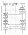
- Fig. 8 is a diagram illustrating a communication procedure in a case in which a new audio device is added to the audio system 10 that has already been configured.
- a component device is one of the audio devices 4 that has already been served as a component of the audio system 10, and, in the present preferred embodiment, is a root device or a node device that has started the internal access point 4A.
- a new device is one of the audio devices 4 to be newly added.
- a guide screen to prompt pressing of the connect button 59A of an audio device 4 (new device) is displayed on the display portion 41.
- a user follows this guide screen and presses the connect button 59A of the new device (S71).
- the controller instructs the component device being one of the audio devices 4 that has been registered to release the stealth mode of the internal access point 4A (S52) . Accordingly, the component device releases the stealth mode of the internal access point 4A, transmits a beacon frame that indicates that the component device itself is present, and enables the new device to passively scan (S61). Subsequently, the controller 1 starts a search of a new device (S53).
- the new device when the connect button 59A is pressed by the user (S71), enters an initial connection mode and searches (passively scans) a connectable access point (S72). Through this search, the new device finds the internal access point 4A of a component device as a connectable access point. As described above, the internal access point 4A has an identifiable SSID that makes it possible to identify a device of the audio system 10 when the device is viewed from the new device, generate a password from the SSID (or MAC address), and connect.
- the new device selects a nearest internal access point (of which the electric wave strength is strongest and of which the connection is easiest) among the internal access points 4A that the new device has found, and temporarily connects to the selected internal access point 4A, using the password that has been generated from the SSID (S73).
- This connection is a temporary connection for obtaining system information, and is not the proper connection for participating in the audio system 10.
- the new device obtains the current system information of the audio system 10 from the connected internal access point 4A (component device) (S62 and S74).
- the system information is information that includes all or a part of the details of the system management table and is periodically updated by the audio device 4-1 used as a root device, and is delivered to other component devices.
- the new device selects the most suitable access point in order to participate in the audio system 10 (S75). This selection is performed on the basis of the electric wave strength of each access point, the number of connection stages from the audio device 4-1 used as a root device, or the number of component devices that are connected to each access point. An access point with a good communication condition (the strong electric wave strength, the fewer number of connection stages, the fewer number of component devices, for example) is selected.
- Fig. 8 illustrates a flow of a case in which the temporarily connected internal access point 4A is determined to be the most suitable for proper connection and a connection destination is not changed. For example, it is a case in which a new device is connected to the internal access point 4A-1 of the audio device 4-1 used as a root device.
- Each device in a case in which the connection destination is changed from the temporarily connected internal access point 4A for proper connection, executes the procedure illustrated in Fig. 9 or Fig. 10 in the section of S100 illustrated in Fig. 8 .
- the proper connection is completed (in the case of Fig.
- the new device receives a new device search message (S53) from the controller 1 and responds to the new device search message (S76).
- S53 a new device search message
- S76 the new device search message
- the new device becomes an element (component) of the audio system 10, and the controller 1 starts controlling music that the new device plays and the volume of the music.
- the new device transmits own device information (such as a MAC address or IP address of the wireless LAN communication portion and an installation location), to the controller 1 (S77) .
- the controller 1 receives the device information (S54), registers the new one of the audio devices 4 in the system management table and the audio control table, and updates both tables (S55).
- the controller 1 transmits the updated system management table to the audio device 4-1 used as a root device (S56), and ends the setup mode (S57) .
- the audio device 4-1 used as a root device periodically delivers system information including all or a part of the details of the system management table to other component devices as a connection confirmation message.
- the notification of the end of the setup mode is transmitted from the controller 1 to all the audio devices 4.
- the controller 1 transmits the notification of the end of the setup mode to the audio device 4-1 used as a root device, and the audio device 4-1 used as a root device may forward the notification of the end of the setup mode to other audio devices 4 of the audio system 10.
- the new device that has received the system information from the audio device 4-1 used as a root device stores the received system information (S78). Subsequently, the new device starts an internal access point 4A in a stealth mode (S79) .
- the component device that has received the system information from the audio device 4-1 used as a root device updates the system information stored inside with the received system information (S63). Then, the component device returns the mode of the internal access point 4A to the stealth mode (S64) .
- a device in which the component device and the new device set the internal access point 4A in the stealth mode is a root device or a node device only, and the processes in S64 and S79 are not performed in a leaf device and a branch device.
- Fig. 9 is a diagram illustrating a communication procedure in a case in which a new device disconnects the temporarily connected internal access point 4A in S75 and reconnects to another internal access point 4A in a tree.
- the new device when another internal access point 4A is selected as a proper connection destination in S75 in Fig. 8 , disconnects the currently temporarily connected internal access point 4A (S81), and properly connects to a selected internal access point 4A, using the address information of the system information (S82). Then, the new device proceeds to S76 of Fig. 8 .
- Fig. 10 is a diagram illustrating a communication procedure in a case in which a new device disconnects the temporarily connected internal access point 4A in S75 and reconnects to an external access point 3 as a branch device.
- the new device when the external access point 3 is selected as a proper connection destination in S75 in Fig. 8 , disconnects the currently temporarily connected internal access point 4A (S91) and starts a temporary access point only at the time of initial connection in stand-alone mode (S92). In other words, the new device starts an internal access point 4A that is not connected to the wired LAN 2 but is connected only to the new device.
- the controller 1 previously stores the SSID and password of a temporary access point only at the time of initial connection.
- the controller 1 finds the temporary access point only at the time of initial connection in the new device search that has been started in S53, then releases a connection with the external access point 3, and connects to a temporary access point that the new device has started (S83).
- the controller 1 since having a high possibility of being unable to obtain the SSID and password of the external access point 3 from the system program of the portable phone 1, asks a user to input the SSID and password of the external access point 3 in this step (S84).
- the input of the SSID may be a method in which a list of currently visible destinations (SSID) is displayed and a user is made to select the SSID of the external access point 3.
- the password (usually shown on the main body of the external access point 3) is input by a user.
- connection information that has been input by a user is transmitted to the new device that has started a temporary access point (S85).
- the new device receives the connection information that has been input by a user (S93).
- the controller after transmitting the connection information (SSID and password) of the external access point 3 to the new device, cancels the connection with the temporary access point (S86) .
- the new device when receiving the connection information of the external access point 3 from the controller 1, stops the temporary access point (S94).
- the controller 1 reconnects to the external access point 3 of which the connection has once been released (S87).
- the new device connects to the external access point 3 using the obtained connection information (S95). Subsequently, returning to the procedure of Fig.
- the controller 1 performs a new device search (S53), and a new device responds to the search (S76). It is to be noted that, in a case in which the system information that has been obtained from the temporarily connected component device includes the connection information of the external access point 3, the processes (S83 to S87, S92 to S94) illustrated in S101 may be omitted, and the new device may reconnect to an external access point as in Fig. 9 .
- Fig. 11(A) to Fig. 11(D) each illustrate an example of a control screen at the time of play control.
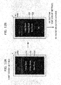
- Fig. 12(A) and Fig. 12(B) each illustrate an example of a control screen at the time of group setting (first group setting) by the first procedure.
- Fig. 13(A) to Fig. 13(C) each illustrate an example of a control screen at the time of play control after the group setting.
- Fig. 14 illustrates an example of a control screen at the time of the group setting (second group setting) by the second procedure.
- Fig. 15 illustrates an example of a control screen at the time of group change setting.
- a control screen is displayed on the display portion 41.
- an initial menu screen illustrated in Fig. 11 (A) is displayed on the display portion 41.
- the controller 1 detects a tap operation by a touch panel 310 and starts the setup mode.
- the controller 1 starts communicating with one of the audio devices 4 of the audio system 10. It is to be noted that, in the present preferred embodiment, control is performed per room (area).
- the controller 1 displays a room selection screen (list screen) as illustrated in Fig. 11(B) , on a control screen (display portion 41).
- a room selection button to select a room in which the one of the audio devices 4 is installed is displayed.
- the room selection button has an image in which the name of the room is displayed on a background image.
- three room selection buttons 93 to 95 are displayed.
- the room selection button 93 is a button to select a living room.
- the room selection button 93 When a user selects the room selection button 93, the audio device 4-1 is selected.
- the room selection button 94 is a button to select a dining room.
- the audio device 4-2 When a user selects the room selection button 94, the audio device 4-2 is selected.
- the room selection button 95 is a button to select a bed room.
- the audio device 4-3 When a user operates (taps) any of the room selection buttons 93 to 95, one of the audio devices 4 in a tapped room is selected. It is to be noted that, while, in the example of Fig. 11(B) , the room selection buttons that are currently displayed on the control screen are three buttons 93 to 95, the other room buttons displayed on the control screen may also be displayed by scrolling the control screen by a touch operation.
- the controller 1 When a user selects (taps) any of the room selection buttons, the controller 1 displays a source selection screen of a selected room.
- the controller 1 on the source selection screen, displays an icon button (source selection image) that illustrates a playable (serviceable) source of at least one of the audio devices 4 that is installed in the selected room.
- Fig. 11(C) illustrates the source selection screen when a dining room is selected by the tap of the room selection button 94.
- icon buttons 97 to 99 that each illustrate a playable source of the audio device 4-3 that is currently installed in the dining room are displayed.
- the icon button 97 is a button to select a CD.
- the icon button 98 is a button to select Net delivery by the delivery server 6.
- the icon button 99 is a button to select a FM broadcast (radio) . When a user selects one of the icon buttons, a selected source is played.
- Fig. 11(C) when the icon button 97 is selected, the controller 1 transmits a command message to start playing a CD, to the audio device 4-3, and displays a play screen (Now Playing screen) of a CD as illustrated in Fig. 11(D) .
- operation portions such as a PLAY/PAUSE button and a volume slider are displayed.
- a user when operating the operation portions, can execute the play and stop of music (music data) of the CD, the volume control of the music, and the like.
- Fig. 11(D) is an example of a control screen in a state in which the group setting is not performed.
- group setting for synchronously playing the same source in a plurality of rooms (audio devices 4).
- group setting an audio device to be a master (master device) of a group and an audio device to be a client (client device) are selected.
- client device an audio device to be a client
- group setting there are two types of group settings: the first group setting and the second group setting. To begin with, a description will be made of the first group setting with reference to Fig. 12 .
- the first group setting is started when a link (Link) button 130 is selected on the screen of Fig. 11(B) .
- a master room selection screen illustrated in Fig. 12(A) is displayed.
- the master room selection screen displays master room selection buttons 121 to 123 for selecting a master to be a supply source of an audio signal (audio source) that is synchronously reproduced (played) in a group.
- the master room selection button 121 is operated, for example, a living room is selected as a master room (master area), and the audio device 4-1 becomes a master of synchronous playing.
- the three buttons 121 to 123 are displayed as master room selection buttons, all buttons of a room that may be selected as a master may be displayed.
- a screen display is switched to a client room selection screen illustrated in Fig. 12 (B) .
- the client room selection screen displays a client room selection button 125 and a client room selection button 126 for selecting a client of the group.
- a check mark is displayed on a check box in the button that has been tapped and becomes a selected state.
- Fig. 12(B) illustrates a state in which both the client room selection button 125 and the client room selection button 126 have been tapped.
- a check mark is displayed on the check box of both the client room selection button 125 and the client room selection button 126, and a dining room and a bedroom serve as client rooms (client area), and the audio device 4-2 and the audio device 4-3 serve as clients.
- a determination (OK) button 126 is operated by a user and the group setting is thus completed.
- the information related to a set group is registered in the audio control table illustrated in Fig. 5 .
- the audio control table illustrated in Fig. 5 like the example described above, information is registered of a group (1A, 1B), in which a master room is a living room (master: audio device 4-1), and client rooms are a dining room and a bedroom (client: audio device 4-2 and audio device 4-3).
- master room is a living room
- client rooms are a dining room and a bedroom
- client audio device 4-2 and audio device 4-3
- the audio source is played in the audio device (master device) serving as a master, and the audio signal is delivered from the master device to the audio device (client device) serving as a client.
- the audio source played in the group is limited to an audio source that the master device may play.
- Fig. 13(A) illustrates an example of the room selection screen in a case in which the group setting is present.
- the group setting is also reflected in the room selection screen.
- the group setting of Fig. 5 is reflected in the room selection screen, and, to a room selection button 931 of the living room as a master room, the room name (Bed Room, Dining Room) of a client room is added, and a blur is added to the background image.
- the room selection button 94 and the room selection button 95 of the dining room and the bed room which are client rooms are grayed out and may not be operated. It is to be noted that the room selection button 94 and the room selection button 95 of a client are not displayed (displaying only the room selection button 931 of a master) and may be made inoperable.
- the controller 1 displays the source selection screen of the audio device 4-1 being a master device.
- the controller 1 after a source is selected on the source selection screen of Fig. 13(B) , displays a play screen as illustrated in Fig. 13(C) , and causes the audio devices 4-1 to 4-3 to execute synchronous playing in a living room, a dining table, and a bedroom.
- the control of synchronous playing may apply a technique such as disclosed in Japanese Unexamined Patent Application Publication No. 2015-100085 .
- the second group setting is started when a link (Link) button 131 is selected on the screen of Fig. 11(D).
- Fig. 11(D) illustrates a play screen (Now Playing screen) that is displayed while an audio source is being played in a room (one of the audio devices 4) that is not grouped.
- the controller 1 proceeds to the second group setting (second procedure) in which a selected room is set to a master room.
- the controller 1 displays a client room selection screen on which the dining room illustrated in Fig. 14 is set to a master room.
- a user on the client room selection screen, operates a client room selection button similarly to the first group setting illustrated in Fig. 12(B) , and selects a client room, and selects a determination (OK) button 126. Then, the setting of a group, for which the room in which the Now Playing screen illustrated in Fig. 11(D) is displayed, to a master room is completed.
- the screen is directly switched to the group setting screen while the playing of the audio source is continued.
- the setting of a group for which the room during playing is set as a main room may be performed.
- the audio source that has been playing in a single room is switched to be played (while being played) in a plurality of rooms (group).
- the client room selection screen of the group to which the room corresponding to the play screen belongs is displayed. Changing settings (resetting and selecting) of a client room may be performed.
- the controller 1 displays a client room selection screen as illustrated in Fig. 15 .
- the controller 1 displays the setting details of the current group on the client room selection screen illustrated in Fig. 15 .
- the controller 1 displays a state in which a check icon is displayed on a check box corresponding to a dining room and a bedroom as a client room.
- a user may cancel (deselect) the display of the check icon by performing a touch operation of the client room selection button 125 or the client room selection button 126 when necessary, and may also add a client room by newly performing a touch operation of another client room selection button. Then, the user selects the determination (OK) button 126 to fix (complete the change setting of) the room (one of the audio devices 4) that belongs to a group. Subsequently, the controller 1 returns a display to the play screen of the living room illustrated in Fig. 13(C) . It is to be noted that the procedure of changing the setting of this group may also be executed during playing of content.
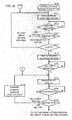
- the controller 1 causes the display portion 41 to display a room selection screen as illustrated in Fig. 11(B) and the like, mainly based on a system management table, an audio control table, and a room table (S151). Then, the controller 1 stands ready until any button is operated on the room selection screen (S152).
- the controller 1 when any of the buttons is operated on the room selection screen (YES in S152), performs a process corresponding to the operated button (S153).
- the controller 1 when the link button 130 is operated, performs a first group setting process (see Fig. 17 ).
- the controller 1 when any one of the room selection buttons is operated, determines whether a room that has been selected by this operation is a client room (S154).
- step S154 This determination is made with reference to the information of the group in the audio control table.
- the controller 1 returns to the process of S151. It is to be noted that, when the room selection button of a client is made inoperable without being displayed, the process of step S154 is unnecessary.
- the controller 1 causes the display portion 41 to display a source selection screen of the selected room as illustrated in Fig. 11(C) and the like (S155). Specifically, the controller 1 displays a source selection screen, mainly based on information of the service of the audio control table of an audio device corresponding to the selected room selection button, and a room table. Then, the controller 1 stands ready until an icon button of any source is operated (S156). The controller 1, when an icon button is operated (YES in S156), displays a play screen ( Fig. 11(D) , for example) corresponding to a selected source (S157).
- the controller 1 stands ready until any of the buttons is operated on the play screen (S158).
- the controller 1 performs a process corresponding to the operated button (S159) .
- the controller 1 transmits a command message of a playing process to the source that is currently selected, to one of the audio devices 4 corresponding to the room of the screen (S160), and returns to the process of step S157.
- the controller 1 performs the second group setting and a group change setting process (see Fig. 18 ).
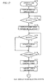
- Fig. 17 is a flow chart illustrating the first group setting process of the controller 1 (control portion 20).
- the controller 1 causes the display portion 41 to display a master room selection screen as illustrated in Fig. 12 (A) (S171), and stands ready until a master room is selected (S172).
- the controller 1 causes the display portion 41 to display a client room selection screen corresponding to the selected master room (S173).
- the client room selection screen displays a client room selection screen in the initial state in which a check mark is not displayed on a check box.
- the controller 1 every time a client room is selected (YES in S174), updates the display of the client room selection screen (S175). In other words, the controller 1 updates a screen so that a check icon is added to the check box of the selected room. In addition, the controller 1, when finding a check icon in the check box of the selected room, updates the screen so that a check icon is deleted. Then, the controller 1 repeats and executes the processes of S174 and S175 until the OK button is pressed to fix the selection (S176). When the selection is fixed (YES in S176), the controller 1 updates the audio control table based on a selection result (S177).
- the controller 1 transmits the updated audio control table to all the audio devices 4-1 to 4-6 that may communicate (S178). Accordingly, each of the audio devices 4-1 to 4-6 obtain the information of whether the device belongs to a group or the information of whether the device is a master of synchronous playing and may perform synchronous playing. Then, the controller 1 proceeds to the process of S151 illustrated in Fig. 16 , and displays a room selection screen. In such a case, as illustrated in Fig. 13(A) , the information of the group that has been updated in S177 is reflected in the room selection screen.
- Fig. 18 is a flow chart illustrating the second group setting and the group change setting process of the controller 1 (control portion 20).
- the controller 1 determines whether a room corresponding to the play screen already belongs to a group (S201). Specifically, the controller 1 makes a determination based on the information of the group of the audio control table. In a case of not belonging to a group (NO in S201), the controller 1 determines that the setting is the second group setting, omits the processes of the master room selection screen displayed by the first group setting, and causes the display portion 41 to display the client room selection screen in which the room corresponding to the play screen as illustrated in Fig. 14 is set to the master room (S202). At such a time, the controller 1 displays a client room selection screen in the initial state in which a check mark is not displayed on a check box, as the client room selection screen. Then, the controller 1 performs the processes of S203 to S207 that are similar processes to S174 to S178.
- a group is set up of which the room corresponding to the play screen is set to a master room.
- the controller 1 determines that the setting is the group change setting, and causes the display portion 41 to display a client room selection screen as illustrated in Fig. 15 and the like (S202). At such a time, on the client room selection screen, the details of the setting of the current group are displayed. In other words, the controller 1 displays a check mark on a check box corresponding to the area or the room that belongs to a group. Subsequently, the controller 1 performs the above described processes of S203 to S207.
- the controller 1 After executing the process of S207, proceeds to the process of S157 illustrated in Fig. 16 and displays the play screen of the master room.
- the group setting may be performed. Moreover, since, in the second group setting, play content has already been determined, there is no way to mistake the content shared in a group by mistake or there is no necessity to determine or select content as a process after the group setting.
- the link button 131 is provided on the source selection screen to make it possible to switch to the second group setting.
- the client room selection button 94 and the client room selection button 95 are grayed out and may not be operated. However, neither the client room selection button 94 nor the client room selection button may be displayed, and only the room selection button 931 of a master may be displayed.
- one audio device is installed in one room
- a plurality of sets of audio devices may be installed in one room.
- one of the plurality of sets of audio devices according to the number of HOPs may be set as a master of synchronous playing.
- the system management table, the audio control table, and the like are automatically generated at the time of the network connection of the audio device.
- a user may directly input required information mainly to the controller 1.
- the room selection screen is mainly displayed to perform the selection and group setting of an audio device that executes playing per room (area), the setting may be performed per audio device.
- the display of room names such as a room selection screen may be displayed under the name of an audio device.
- the present invention may be applied to a content player such as an audio visual (AV) device with a video play function.
- the present invention may also be applied to a system in which an audio device and an AV device are mixed.
- the present invention may be applied to a device that performs a predetermined operation, other than a content player.
- the control terminal is achieved by the portable phone 1 in which the audio system control program 70 (application program) is installed, the control terminal may be achieved by a configuration other than the portable phone.
- the control terminal may be a tablet in which the audio system control program 70 is installed or may be an exclusive terminal device.
Landscapes
- Engineering & Computer Science (AREA)
- Signal Processing (AREA)
- Multimedia (AREA)
- Automation & Control Theory (AREA)
- Human Computer Interaction (AREA)
- Computer Networks & Wireless Communication (AREA)
- Physics & Mathematics (AREA)
- Acoustics & Sound (AREA)
- Computing Systems (AREA)
- Circuit For Audible Band Transducer (AREA)
- Mobile Radio Communication Systems (AREA)
Abstract
Description
- A preferred embodiment of the present invention relates to a control terminal and a method for controlling a device, wherein the control terminal and the method group two or more devices and cause the devices to perform a synchronized operation in the group.
- In recent years, an audio system has been disclosed, in which a plurality of audio devices (playing devices) arranged in each room (area), such as a living room and a bedroom, are connected to a network (wireless network, in particular), and in which an operation such as content playing of each of the audio devices is controlled by a portable terminal device. A user, by operating a portable terminal device, can cause one selected audio device to execute content playing or the like. In addition, the user, by operating a portable terminal device, can also specify (select) a plurality of audio devices to perform a group setting. Then, the user can cause the audio devices that belong to a group to execute synchronous playing of the same content.
- Patent Literature 1: Japanese Unexamined Patent Application Publication No.
2013-251594 - In the group setting of the above described audio system, it is necessary to select a master device as a supply source of content that is synchronously played, and a client device that receives the content from the master device, therefore the operation may become complicated for a user.
- In view of the foregoing, an object of a preferred embodiment of the present invention is to allow a control terminal to more easily perform group setting, the control terminal grouping two or more devices and causing the devices to perform a synchronized operation in the group.
- A control terminal according to a preferred embodiment of the present invention is provided with a selection portion and a control portion. The selection portion receives an operation to select one or more devices and receives a group setting operation of the devices. The control portion, in case the group setting operation is performed while the devices are not selected, receives a selection of a master device in the group and a client device that synchronizes the master device, and groups these selected devices. In addition, the control portion, in case the group setting operation is performed while one device is previously selected, sets a previously selected device as a master device, receives the selection of a client device that synchronizes the master device, and groups the selected devices.
- According to a preferred embodiment of the present invention, the group setting of devices is able to be more easily performed, the group setting causing the devices to operate synchronously.
-
-
Fig. 1 shows a configuration diagram of an audiosystem. -
Fig. 2 shows a block diagram of the portable phone that serves as a controller. -
Fig. 3 is a block diagram of an audio device. -
Fig. 4 illustrates an example of a system management table that is set to a host device and a controller. -
Fig. 5 illustrates an example of an audio control table that is set to the controller. -
Fig. 6 illustrates an example of a room table that is set to the controller. -
Fig. 7 shows a diagram illustrating a communication procedure of the controller and the audio device. -
Fig. 8 shows a diagram illustrating a communication procedure of the controller and the audio device. -
Fig. 9 shows a diagram illustrating a communication procedure of the controller and the audio device. -
Fig. 10 shows a diagram illustrating a communication procedure of the controller and the audio device. -
Fig. 11(A) illustrates an example of a control screen (initial menu screen) of the portable phone. -
Fig. 11(B) illustrates an example of a control screen (room selection screen) of the portable phone. -
Fig. 11(C) illustrates an example of a control screen (source selection screen) of the portable phone. -
Fig. 11(D) illustrates an example of a control screen (play screen) of the portable phone. -
Fig. 12 (A) illustrates an example of a control screen (master room selection screen) of the portable phone. -
Fig. 12(B) illustrates an example of a control screen (client room selection screen) of the portable phone. -
Fig. 13(A) illustrates an example of a control screen (room selection screen) of the portable phone. -
Fig. 13(B) illustrates an example of a control screen (source selection screen) of the portable phone. -
Fig. 13(C) illustrates an example of a control screen (play screen) of the portable phone. -
Fig. 14 illustrates an example of a control screen (client room selection screen) of the portable phone. -
Fig. 15 illustrates an example of a control screen (client room selection screen) of the portable phone. -
Fig. 16 shows a flow chart illustrating a control process of a controller (control portion). -
Fig. 17 shows a flow chart illustrating a first group setting process of the controller (control portion). -
Fig. 18 shows a flow chart illustrating the second group setting and a group change setting process of the controller (control portion). -
Fig. 1 shows a diagram illustrating a configuration of an audio system. Theaudio system 10 has a plurality of audio devices 4 (4-1 to 4-6) and a multifunctional portable phone (portable terminal device) 1. The plurality of the audio devices 4 (4-1 to 4-6) and the portableterminal devices 1 are connected in anetwork 9 including awired LAN 2 and an access point (external access point) 3. Theportable terminal device 1 is a control terminal, and serves as acontroller 1. Each of theaudio devices 4 transmits and receives an audio signal mutually through thenetwork 9. Thecontroller 1 transmits a command message to each of theaudio devices 4 through thenetwork 9. - Each of the audio devices 4 (hereinafter also referred to as a component device) has a wired LAN function and two wireless LAN functions. Each of the
audio devices 4 is able to start an access point using one of the two wireless LAN functions. The access point started by each of theaudio devices 4 is called aninternal access point 4A. To theinternal access point 4A, one of the lower-level audio devices 4 is connected. Theinternal access point 4A usually (except the time of an initial connection to be described later) operates in a stealth mode, and the presence of theinternal access point 4A is hardly known to other devices. The other of the wireless LAN functions serves as a slave machine of the wireless LAN, and is connected to theinternal access point 4A of one of the higher-level audio devices 4 or anexternal access point 3. - The access point (external access point) 3 is connected to the
wired LAN 2. The audio device 4-1 is connected to thewired LAN 2 by a cable. The audio device 4-2 and the audio device 4-3 are connected to aninternal access point 4A-1 of the higher-level audio device 4-1 by the wireless LAN. The audio device 4-4 is connected to aninternal access point 4A-2 of the higher-level audio device 4-2 by the wireless LAN. In addition, the audio device 4-5 is connected to aninternal access point 4A-3 of the higher-level audio device 4-3 by the wireless LAN. The audio device 4-6 is connected to theexternal access point 3. - In the present preferred embodiment, the
network 9 is configured by thewired LAN 2, theexternal access point 3, and the wireless LAN including theinternal access point 4A. Thewired LAN 2 uses, for example, Ethernet (registered trademark: IEEE 802.3). The wireless LAN uses Wi-Fi (IEEE 802.11g). Moreover, to thenetwork 9, a delivery server 6 is connected from the wiredLAN 2 through the gateway (not shown) and the Internet 5. The delivery server 6 delivers music data to theaudio devices 4. - Each of the
audio devices 4 is called a root device, a node device, a leaf device, and a branch device, according to the configuration of the connection to the wiredLAN 2. The root device is the top-level device connected to the wiredLAN 2 directly (with a cable), and the audio device 4-1 is a root device inFig. 1 . The root device is an audio device that has first been registered at the time of the configuration of theaudio system 10, and serves as a reference point of theaudio system 10. The root device starts theinternal access point 4A to connect one of the lower-level audio devices 4 to the network and causing the one of the lower-level audio devices 4 to participate in theaudio system 10. The music information that is reproduced by at least one of the audio devices 4 (a node device and a leaf device) that is connected below the root device is all transmitted through the root device. - The node device is a middle-level device connected to the root device (
internal access point 4A of the root device) by the wireless LAN, and the audio device 4-2 and the audio device 4-3 are node devices inFig. 1 . The node device starts theinternal access point 4A to connect one of the lower-level audio devices 4 to the network and cause the lower-level audio devices 4 to participate in theaudio system 10. The music information that is reproduced by the audio devices 4 (a leaf device) that are connected to a device below the node device is all transmitted through the node device. - The leaf device is a lower-level device connected to the node device (
internal access point 4A of the node device) by the wireless LAN. The audio device 4-4 and the audio device 4-5 are leaf devices inFig. 1 . It is to be noted that the leaf device does not start theinternal access point 4A, but may be configured to start theinternal access point 4A. - The branch device is an
audio device 4 that is connected to theexternal access point 3 by the wireless LAN, separately from a tree having a root device as the top and that communicates with otheraudio devices 4 in theaudio system 10 through the wiredLAN 2, and, inFig. 1 , the audio device 4-6 is a branch device. It is to be noted that the branch device does not start theinternal access point 4A, but may be configured to start theinternal access point 4A. - In such an audio system, in order to transmit a high quality audio signal, the root device is allowed to connect up to two node devices. In addition, each of the node devices is allowed to connect up to two leaf devices. The hierarchy of connection using the
internal access point 4A comprises up to three hierarchy levels of a root device to a node device to a leaf device. Therefore, the tree of a wireless LAN including a root device as the top device makes it possible to connect up to seven audio devices including the root device. Five audio devices 4 (4-1 to 4-5) are connected to the tree illustrated inFig. 1 . Although there is no limitation in the number of branch devices, as a controlled target of thecontroller 1, the number ofaudio devices 4 is limited to up to ten audio devices in theentire audio system 10. However, in the present invention, the maximum number such as the number of hierarchies of a tree and the number of lower-level devices connectable to each of theaudio devices 4 is not limited to the present preferred embodiment. - In addition, each of the audio devices 4-1 to 4-6, as shown in
Fig. 1 , is arranged in a room (area) of a living room, a dining room, a bedroom, a kitchen, a room A, and a room B that are in the same building. - Although each of the audio devices 4-1 to 4-6 of the
audio system 10 is able to independently play separate content, in theaudio system 10, a plurality of audio devices 4-1 to 4-6 are able to be grouped, and the grouped audio devices 4-1 to 4-6 synchronously play the same content. The content is for example music (audio) . The music is music data stored in a CD, a hard disk, or the like that are included in each of the audio devices 4-1 to 4-6, and the file format of the music data is for example MP3, WAV, SoundVQ (registered trademark), WMA (registered trademark), or AAC. - The
portable phone 1 serves as an audio system controller (hereinafter referred to as a controller) 1 by starting an audio system control program 70 (seeFig. 2 ). The portable phone 1 (controller 1) communicates with each of theaudio devices 4 that belong to theaudio system 10, through thenetwork 9. Thecontroller 1, through such communication, controls an audio source to be played in each of the audio devices 4-1 to 4-6 in the audio system 10 (each of theaudio devices 4 plays the music, which is delivered to each of theaudio devices 4, or the like, for example) or the sound volume, and the like, in an integrated manner. Moreover, each of theaudio devices 4 communicates with otheraudio devices 4 through thenetwork 9, and mutually transmits and receives an audio signal. - In addition, the
controller 1 receives an operation input to set a group that performs the synchronous playing. The group is able to be set up per room (area) . Then, thecontroller 1 is able to allow theaudio devices 4, which are arranged in a room belonging to the group, to perform synchronous playing. - Subsequently, with reference to the block diagram in
Fig. 2 , a description will be made of a configuration of aportable phone 1. Theportable phone 1 is a multifunctional telephone that is a so-called smartphone. Theportable phone 1 has a 3G/4G communication function which is a portable communication network, a wireless LAN (Wi-Fi) communication function, and a Bluetooth (registered trademark) communication function. By starting the audiosystem control program 70, which is an application program, theportable phone 1 serves as acontroller 1, communicates with theaudio devices 4 of the audio system through the network, transmits a command message according to the operation of a user, to theaudio devices 4, and controls the audio system. - The
portable phone 1, on a bus 26, has acontrol portion 20, anoperation portion 30, amedia interface 31, a Wi-Fi communication circuit 32, a 3G/4G communication circuit 33, and a Bluetooth (registered trademark)communication portion 34. Thecontrol portion 20 includes aCPU 21, a ROM (flash memory) 22, aRAM 23, animage processor 24, and anaudio processor 25. To theimage processor 24, a video RAM (VRAM) 40 is connected, and, to theVRAM 40, adisplay portion 41 is connected. Thedisplay portion 41 includes a liquid crystal display. On the display, a standby screen, a telephone number, and the like are displayed. When serving as thecontroller 1, a screen for controlling theaudio devices 4 is displayed. To theaudio processor 25 anamplifier 42 including a D/A converter is connected, and to the amplifier 42 aspeaker 16 is connected. - The
image processor 24 is provided with a GPU (Graphics Processing Unit) that generates various images such as a standby screen and a telephone number. When the audiosystem control program 70 is started, theimage processor 24 generates the image of an audio controller according to instruction of theCPU 21, and develops the image on theVRAM 40. The image developed on theVRAM 40 is displayed on thedisplay portion 41. - The
audio processor 25 has a DSP (Digital Signal Processor) that encodes and decodes telephone call sounds. Theaudio processor 25 outputs the decoded or generated sound to theamplifier 42. Theamplifier 42 amplifies this sound signal and outputs a resulting sound signal to thespeaker 16. - The wireless
LAN communication circuit 32 performs wireless communication with theaccess point 3 in conformity with the IEEE 802.11g standard, and communicates with theaudio devices 4 through theaccess point 3. The 3G/4G communication circuit 33 performs a voice communication and a data communication through a portable telephone communication network. TheBluetooth communication portion 34 communicates with other Bluetooth compatible devices and for example performs transmission and reception of an audio signal. - The
operation portion 30 includes a touch panel 310 (mainly seeFig. 11 ) that is formed on thedisplay portion 41 and detects a touch operation and a flick operation on thetouch panel 310. When the audiosystem control program 70 is started, on the display portion 41 a plurality of operation elements such as a setup button and a scan button are displayed. Theoperation portion 30 detects the touch operation of a user and the coordinates of the operation by thetouch panel 310, and determines which operation element has been operated. - The
media interface 31 is connected to amemory card 15. Thememory card 15 is for example a micro SD card. The audiosystem control program 70 is stored in thememory card 15 or theROM 22. In the present preferred embodiment, the audiosystem control program 70 is stored in thememory card 15, as shown inFig. 2 . It is to be noted that the audiosystem control program 70 may be downloaded through the 3G/4G data communication or the wireless LAN data communication or may be previously stored in theROM 22 or thememory card 15. In addition, in thememory card 15, astorage area 71 that stores the configuration of the audio system is set. - In the
ROM 22, a basic program for executing a telephone call and an application program of thisportable phone 1 is stored. TheROM 22 is a flash memory, and besides the basic program, is also capable of storing an application program that has been downloaded. In theRAM 23, a work area that is used when theCPU 21 executes the audiosystem control program 70 is set. Thecontrol portion 20, when theCPU 21 executes the audiosystem control program 70, functions as a selection portion, and receives the operation input to set a group that performs synchronous playing. - Subsequently, a description will be made of a configuration of one of the
audio devices 4 with reference toFig. 3 . The one of theaudio devices 4 has acontrol portion 50, anaudio processing portion 51, anoperation portion 59, a wireless LAN communication portion (RF module) 56, a wirelessLAN communication portion 57, and a wiredLAN communication portion 58. Theoperation portion 59 has aconnect button 59A in addition to a volume operation element (not shown). Thecontrol portion 50 includes a CPU and a memory and stores an audio system program. Thecontrol portion 50 controls the operation of theaudio processing portion 51, and the wirelessLAN communication portion 56, the wirelessLAN communication portion 57, and the wiredLAN communication portion 58 by the audio system program. Accordingly, theaudio device 4 functions as a play device that plays content and also as a synchronous play controller to be a master device that controls the synchronous playing. In addition, thecontrol portion 50, when theconnect button 59A is pressed, executes an initial connection operation that is an operation to connect thisaudio device 4 to thenetwork 9. The details of the initial connection operation will be described below. - The wireless
LAN communication portion 56 performs wireless communication by the wireless LAN standards such as IEEE 802.11g with theexternal access point 3 or theinternal access point 4A of one of the higher-level audio devices 4. Moreover, another wirelessLAN communication portion 57 is started as an access point (internal access point 4A), and relays other audio devices (audio device 4-2 or audio device 4-3, for example) to the wiredLAN 2. Furthermore, the wirelessLAN communication portion 57 is started as a temporary access point for initial connection at the time of initial connection, and communicates with the controller 1 (portable phone 1) . The operation at the time of initial connection will be described below. It is to be noted that both the wirelessLAN communication portion 56 and the wirelessLAN communication portion 57 may be implemented by operating one piece of hardware in a time-sharing manner. The wiredLAN communication portion 58 has a cable connector, and performs communication by the communication standards such as IEEE 802.3 through the wiredLAN 2 and theaccess point 3. The controller (portable phone) 1 is connected to theaccess point 3, and thecontrol portion 50 communicates with thecontroller 1 through thenetwork 9, transmits an operation state, and receives a command message. - The SSID and password of the
internal access point 4A are provided as a character string that is able to be found out from the MAC address of the wirelessLAN communication portion 57. For example, the MAC address is an octet expressed as an SSID and the like, and the lower three octets (model ID + serial number) are used as a password and the like. Accordingly, an audio device to newly participate in the audio system is able to find theinternal access point 4A based on the SSID, that is, based on the vendor ID of the MAC address and model ID, and is able to generate a password by itself, and is able to connect to theinternal access point 4A. Accordingly, the input of an SSID or a password by a user when connecting to theinternal access point 4A, may be omitted. It is to be noted that a method of generating an SSID of theinternal access point 4A and a password is not limited to the above-described method. - The
audio processing portion 51 has atuner 52, anaudio circuit 53, and apower amplifier 54. Thetuner 52 receives an audio signal from an FM broadcast or the Internet, and inputs the audio signal into theaudio circuit 53. Theaudio circuit 53 performs a process such as equalizing or volume adjustment to an input audio signal. In addition, theaudio circuit 53 outputs a processed audio signal to thepower amplifier 54. Thepower amplifier 54 amplifies the input audio signal, and outputs an amplified audio signal to aspeaker 55 that is connected externally. Thespeaker 55 emits the input audio signal as sound. - It is to be noted that, although the audio devices 4-1 to 4-6 may be different devices, the respective basic configuration of a communication function and an audio signal processing function is illustrated in
Fig. 3 . -
Fig. 4 andFig. 5 each illustrate an example of a table that manages theaudio system 10.Fig. 4 is a system management table that manages the connection configuration of each of theaudio devices 4 in thenetwork 9.Fig. 5 is an audio control table that manages the operation of each of theaudio devices 4 in theaudio system 10. The system management table is used mainly by the audio device 4-1 to be a root device in order to manage network connection. In addition, the audio control table is used, mainly by thecontroller 1, to control the play of an audio source. - The system management table is a table that stores the connection configuration of each of the audio devices 4 (a component device) and the
audio system 10 that thecontroller 1 creates at the time of configuration of theaudio system 10. In addition, when a new one of theaudio devices 4 is added to theaudio system 10, thecontroller 1 updates the system management table by adding the new one of theaudio devices 4. The system management table that has been created or added and updated is transmitted from thecontroller 1 to the audio device 4-1 to be a root device. Then, the system management table, during the operation of theaudio system 10, is updated by the audio device 4-1 used as a root device every time the disconnection or the reconnection of any of the component devices occurs. Furthermore, the audio device 4-1 used as a root device periodically transmits all or a part of the details of the system management table as system information to each of the component devices and thecontroller 1. Accordingly, each of the component devices and thecontroller 1 are always able to store the latest system information. The detailed operation of transmission of the above system information will be described below. - The system management table is identified by a system ID for identifying the
audio system 10. Each of the component devices associates a device ID of each device and stores information such as the higher-level side (slave machine side) and lower-level side (internal access point side) MAC address (that is, the MAC address of each of the wirelessLAN communication portions 56 and 57), the higher-level side and lower-level side IP address (that is, the IP address of each of the wirelessLAN communication portions 56 and 57), the number of connection stages (the number of HOPs) from the audio device 4-1 used as a root device, the presence or absence of a start of an internal access point, or the number of lower-level devices (the number of children) connected to theinternal access point 4A. - It is to be noted that, while each of the component devices has an individual IP address, for the
audio system 10, a multicast address is set as a multicasting group. Each of the component devices, by transmitting an IP packet of the system information to the multicast address, is able to cause all the component devices of theaudio system 10 to receive this system information packet. It is to be noted that each of the component devices may transmit the system information packet to the IP address of each of the component devices by unicast, but transmitting by multicast may reduce the load of thenetwork 9. - The audio control table illustrated in
Fig. 5 associates a device ID of each device and stores various types of setting information such as the higher-level side IP address (the IP address of the wireless LAN communication portion 56) of each of the component devices, a model, an installation location, a group, service, a volume value, and a display name. Each column of the audio control table and each column of the system management table are associated with each other by the device ID. Thecontroller 1 creates a control screen (seeFig. 11 to Fig. 15 ) based on the details of the audio control table, and receives control of each of the component devices by a user. - The installation location is information that specifies a room (area) in which the audio device is installed. Although a name is displayed in
Fig. 5 , a room ID of a room in which a device is installed may for example be registered in the installation location. The information of the installation location (room ID) is set for each of theaudio devices 4, for example, when the audio device is installed in a room. The room ID is associated with each piece of information of a room table illustrated inFig. 6. Fig. 6 illustrates an example of the room table. In the room table, information related to rooms in which theaudio devices 4 are arranged is registered. Specifically, in the room table a room ID, and associated a room name and a background image are registered. The room name is name data of a room such as a living room (Living Room). The background image is an image used as a background image such as a room selection button (area selection image) displayed on the control screen in theportable phone 1. For example, the file name of the image data is registered. It is to be noted that the room name and the background image may be optionally set by a user, operating thecontroller 1. - The group is information of a group to which an audio device (room) belongs, and indicates a group that performs synchronous playing of the above described content. In the present preferred embodiment, only one group is set up. In addition, an audio device that belongs to one group is set to either a synchronous playing master or a synchronous playing client.
- The synchronous playing master takes charge of the supply from an audio source to the entire group and the control of synchronous playing and also functions as a device that also performs synchronous playing. The synchronous playing client plays content according to the instruction of the synchronous playing master. For example, "1A" indicated in the same drawing indicates an audio playing device (room) that belongs to a group as a synchronous playing master. In addition, "1B" indicates an audio playing device (room) that belongs to a group as a synchronous playing slave. The others except for "1A" and "1B" indicate audio playing devices that do not belong to a group. The group may be set per room (area) by operating the
controller 1 as described above. The details will be described below. - The service indicates source information of an FM broadcast or content that each device such as a CD (CD player) may play.
- In a case of configuring the
audio system 10, a user first sets the audio device 4-1 used as a root device, and configures theaudio system 10. Subsequently, the user adds theaudio devices 4 other than the audio device 4-1 used as a root device, to theaudio system 10. The user works in the following procedure. To begin with, the user connects the audio device 4-1 used as a root device, to a cable of the wiredLAN 2. The user starts thecontroller 1 in a setup mode. The user presses theconnect button 59A of the audio device 4-1. When the user performs the above work, thecontroller 1 and the audio device 4-1 used as a root device communicate with each other to automatically configure theaudio system 10. Subsequently, in a case of adding a new one of theaudio devices 4 to theaudio system 10, the user starts thecontroller 1 in a setup mode, turns on the power of the new one of theaudio devices 4 to be added (starts the wirelessLAN communication portions 56 and 57), and presses theconnect button 59A. The new one of theaudio devices 4, of which theconnect button 59A has been pressed, communicates with thecontroller 1 and the audio device 4-1 used as a root device, automatically generates a password from the above described SSID, and is automatically added to theaudio system 10. - With reference to
Fig. 7 to Fig. 10 , a description will be made of a communication procedure of thecontroller 1 and one of theaudio devices 4 at the time of configuration of theaudio system 10 and at the time of addition of a new one of theaudio devices 4 to theaudio system 10. -
Fig. 7 is a diagram illustrating a communication procedure of thecontroller 1 and the audio device 4-1 used as a root device when anaudio system 10 is newly configured. Theportable phone 1, when the audiosystem control program 70 is started, functions as acontroller 1. When thecontroller 1 enters a setup mode by the operation of a user (S31), on thedisplay portion 41, a guide screen to prompt pressing of theconnect button 59A of the audio device 4-1 is displayed. The user sees the guide screen and presses theconnect button 59A of the audio device 4-1 (S41). Subsequently, thecontroller 1 searches a new audio device that is connected to the wired LAN 2 (S32). This search is performed by transmitting a message requesting a reply, that is, by a method such as polling. The audio device 4-1 responds to this search (S42). Accordingly, thecontroller 1 and the audio device 4-1 start mutual communication through the wiredLAN 2 and theaccess point 3. - The audio device 4-1 transmits its own device information (such as a MAC address or IP address of the wireless LAN communication portion), to the controller 1 (S43). The
controller 1 configures anew audio system 10 in which this audio device 4-1 is used as a root device. Thecontroller 1 assigns a system ID to the audio system 10 (S34), creates the system management table and the audio control table that are respectively illustrated inFig. 4 andFig. 5 , and configures theaudio system 10 in which one of theaudio devices 4 is currently communicating is used as a root device (S35). When theaudio system 10 is configured, thecontroller 1 transmits the system management table to the audio device 4-1 that has been a root device (S36), and ends the setup mode (S37). The audio device 4-1 receives the system management table from the controller 1 (S44) and stores the system management table (S45). Accordingly, theaudio system 10 in which the audio device 4-1 is used as a root device that is a key element (component) is configured. Hereinafter, music to be played, the volume of the music, and the like are controlled by thecontroller 1. The audio device 4-1 starts an access point in a stealth mode (S46). -
Fig. 8 is a diagram illustrating a communication procedure in a case in which a new audio device is added to theaudio system 10 that has already been configured. A component device is one of theaudio devices 4 that has already been served as a component of theaudio system 10, and, in the present preferred embodiment, is a root device or a node device that has started theinternal access point 4A. A new device is one of theaudio devices 4 to be newly added. - When the
portable phone 1 that functions as thecontroller 1 enters the setup mode by the operation of the user (S51), a guide screen to prompt pressing of theconnect button 59A of an audio device 4 (new device) is displayed on thedisplay portion 41. A user follows this guide screen and presses theconnect button 59A of the new device (S71). The controller instructs the component device being one of theaudio devices 4 that has been registered to release the stealth mode of theinternal access point 4A (S52) . Accordingly, the component device releases the stealth mode of theinternal access point 4A, transmits a beacon frame that indicates that the component device itself is present, and enables the new device to passively scan (S61). Subsequently, thecontroller 1 starts a search of a new device (S53). - The new device, when the
connect button 59A is pressed by the user (S71), enters an initial connection mode and searches (passively scans) a connectable access point (S72). Through this search, the new device finds theinternal access point 4A of a component device as a connectable access point. As described above, theinternal access point 4A has an identifiable SSID that makes it possible to identify a device of theaudio system 10 when the device is viewed from the new device, generate a password from the SSID (or MAC address), and connect. The new device selects a nearest internal access point (of which the electric wave strength is strongest and of which the connection is easiest) among theinternal access points 4A that the new device has found, and temporarily connects to the selectedinternal access point 4A, using the password that has been generated from the SSID (S73). This connection is a temporary connection for obtaining system information, and is not the proper connection for participating in theaudio system 10. Then, the new device obtains the current system information of theaudio system 10 from the connectedinternal access point 4A (component device) (S62 and S74). The system information is information that includes all or a part of the details of the system management table and is periodically updated by the audio device 4-1 used as a root device, and is delivered to other component devices. The new device, based on the obtained system information, selects the most suitable access point in order to participate in the audio system 10 (S75). This selection is performed on the basis of the electric wave strength of each access point, the number of connection stages from the audio device 4-1 used as a root device, or the number of component devices that are connected to each access point. An access point with a good communication condition (the strong electric wave strength, the fewer number of connection stages, the fewer number of component devices, for example) is selected. - The example of
Fig. 8 (example without executing S100) illustrates a flow of a case in which the temporarily connectedinternal access point 4A is determined to be the most suitable for proper connection and a connection destination is not changed. For example, it is a case in which a new device is connected to theinternal access point 4A-1 of the audio device 4-1 used as a root device. Each device, in a case in which the connection destination is changed from the temporarily connectedinternal access point 4A for proper connection, executes the procedure illustrated inFig. 9 orFig. 10 in the section of S100 illustrated inFig. 8 . When the proper connection is completed (in the case ofFig. 8 , after the temporary connection is changed to the proper connection), the new device receives a new device search message (S53) from thecontroller 1 and responds to the new device search message (S76). This enables the new device to communicate with thecontroller 1. Accordingly, the new device becomes an element (component) of theaudio system 10, and thecontroller 1 starts controlling music that the new device plays and the volume of the music. - The new device transmits own device information (such as a MAC address or IP address of the wireless LAN communication portion and an installation location), to the controller 1 (S77) . The
controller 1 receives the device information (S54), registers the new one of theaudio devices 4 in the system management table and the audio control table, and updates both tables (S55). Thecontroller 1 transmits the updated system management table to the audio device 4-1 used as a root device (S56), and ends the setup mode (S57) . The audio device 4-1 used as a root device periodically delivers system information including all or a part of the details of the system management table to other component devices as a connection confirmation message. The notification of the end of the setup mode is transmitted from thecontroller 1 to all theaudio devices 4. Alternatively, thecontroller 1 transmits the notification of the end of the setup mode to the audio device 4-1 used as a root device, and the audio device 4-1 used as a root device may forward the notification of the end of the setup mode to otheraudio devices 4 of theaudio system 10. - The new device that has received the system information from the audio device 4-1 used as a root device stores the received system information (S78). Subsequently, the new device starts an
internal access point 4A in a stealth mode (S79) . In addition, the component device that has received the system information from the audio device 4-1 used as a root device updates the system information stored inside with the received system information (S63). Then, the component device returns the mode of theinternal access point 4A to the stealth mode (S64) . By the above processes, the user can add a new device to theaudio system 10 that has already been configured. It is to be noted that a device in which the component device and the new device set theinternal access point 4A in the stealth mode is a root device or a node device only, and the processes in S64 and S79 are not performed in a leaf device and a branch device. -
Fig. 9 is a diagram illustrating a communication procedure in a case in which a new device disconnects the temporarily connectedinternal access point 4A in S75 and reconnects to anotherinternal access point 4A in a tree. The new device, when anotherinternal access point 4A is selected as a proper connection destination in S75 inFig. 8 , disconnects the currently temporarily connectedinternal access point 4A (S81), and properly connects to a selectedinternal access point 4A, using the address information of the system information (S82). Then, the new device proceeds to S76 ofFig. 8 . -
Fig. 10 is a diagram illustrating a communication procedure in a case in which a new device disconnects the temporarily connectedinternal access point 4A in S75 and reconnects to anexternal access point 3 as a branch device. The new device, when theexternal access point 3 is selected as a proper connection destination in S75 inFig. 8 , disconnects the currently temporarily connectedinternal access point 4A (S91) and starts a temporary access point only at the time of initial connection in stand-alone mode (S92). In other words, the new device starts aninternal access point 4A that is not connected to the wiredLAN 2 but is connected only to the new device. Thecontroller 1 previously stores the SSID and password of a temporary access point only at the time of initial connection. In other words, the SSID and password of the temporary access point only at the time of initial connection are previously written as data in the audiosystem control program 70. Therefore, thecontroller 1 finds the temporary access point only at the time of initial connection in the new device search that has been started in S53, then releases a connection with theexternal access point 3, and connects to a temporary access point that the new device has started (S83). Thecontroller 1, since having a high possibility of being unable to obtain the SSID and password of theexternal access point 3 from the system program of theportable phone 1, asks a user to input the SSID and password of theexternal access point 3 in this step (S84). The input of the SSID may be a method in which a list of currently visible destinations (SSID) is displayed and a user is made to select the SSID of theexternal access point 3. The password (usually shown on the main body of the external access point 3) is input by a user. - Then, the connection information that has been input by a user is transmitted to the new device that has started a temporary access point (S85). The new device receives the connection information that has been input by a user (S93). The
controller 1, after transmitting the connection information (SSID and password) of theexternal access point 3 to the new device, cancels the connection with the temporary access point (S86) . The new device, when receiving the connection information of theexternal access point 3 from thecontroller 1, stops the temporary access point (S94). Thecontroller 1 reconnects to theexternal access point 3 of which the connection has once been released (S87). The new device connects to theexternal access point 3 using the obtained connection information (S95). Subsequently, returning to the procedure ofFig. 8 , thecontroller 1 performs a new device search (S53), and a new device responds to the search (S76). It is to be noted that, in a case in which the system information that has been obtained from the temporarily connected component device includes the connection information of theexternal access point 3, the processes (S83 to S87, S92 to S94) illustrated in S101 may be omitted, and the new device may reconnect to an external access point as inFig. 9 . - Subsequently, with reference to the control screen (display details of the display portion 41) of the controller 1 (portable phone 1) in the
audio system 10 illustrated inFig. 11 to Fig. 15 , a description will be made of a control procedure (playing procedure and group setting procedure) of one of theaudio devices 4 using thecontroller 1.Fig. 11(A) to Fig. 11(D) each illustrate an example of a control screen at the time of play control.Fig. 12(A) and Fig. 12(B) each illustrate an example of a control screen at the time of group setting (first group setting) by the first procedure.Fig. 13(A) to Fig. 13(C) each illustrate an example of a control screen at the time of play control after the group setting.Fig. 14 illustrates an example of a control screen at the time of the group setting (second group setting) by the second procedure.Fig. 15 illustrates an example of a control screen at the time of group change setting. - When the
controller 1 is started, on thedisplay portion 41, a control screen is displayed. First, an initial menu screen illustrated inFig. 11 (A) is displayed on thedisplay portion 41. When a user taps asetup button 91, thecontroller 1 detects a tap operation by atouch panel 310 and starts the setup mode. In addition, when a user similarly taps asystem connection button 92, thecontroller 1 starts communicating with one of theaudio devices 4 of theaudio system 10. It is to be noted that, in the present preferred embodiment, control is performed per room (area). - To begin with, a description will be made of a play procedure for causing the one of the
audio devices 4 to play an audio source. When communication with theaudio devices 4 is started, the controller 1 (portable phone 1) displays a room selection screen (list screen) as illustrated inFig. 11(B) , on a control screen (display portion 41). On the room selection screen, a room selection button to select a room in which the one of theaudio devices 4 is installed is displayed. The room selection button has an image in which the name of the room is displayed on a background image. In the example ofFig. 11(B) , threeroom selection buttons 93 to 95 are displayed. Theroom selection button 93 is a button to select a living room. When a user selects theroom selection button 93, the audio device 4-1 is selected. Theroom selection button 94 is a button to select a dining room. When a user selects theroom selection button 94, the audio device 4-2 is selected. Theroom selection button 95 is a button to select a bed room. When a user selects theroom selection button 95, the audio device 4-3 is selected. When a user operates (taps) any of theroom selection buttons 93 to 95, one of theaudio devices 4 in a tapped room is selected. It is to be noted that, while, in the example ofFig. 11(B) , the room selection buttons that are currently displayed on the control screen are threebuttons 93 to 95, the other room buttons displayed on the control screen may also be displayed by scrolling the control screen by a touch operation. - When a user selects (taps) any of the room selection buttons, the
controller 1 displays a source selection screen of a selected room. Thecontroller 1, on the source selection screen, displays an icon button (source selection image) that illustrates a playable (serviceable) source of at least one of theaudio devices 4 that is installed in the selected room.Fig. 11(C) illustrates the source selection screen when a dining room is selected by the tap of theroom selection button 94. On this source selection screen,icon buttons 97 to 99 that each illustrate a playable source of the audio device 4-3 that is currently installed in the dining room are displayed. - The
icon button 97 is a button to select a CD. Theicon button 98 is a button to select Net delivery by the delivery server 6. Theicon button 99 is a button to select a FM broadcast (radio) . When a user selects one of the icon buttons, a selected source is played. - For example, in
Fig. 11(C) , when theicon button 97 is selected, thecontroller 1 transmits a command message to start playing a CD, to the audio device 4-3, and displays a play screen (Now Playing screen) of a CD as illustrated inFig. 11(D) . On this screen, operation portions such as a PLAY/PAUSE button and a volume slider are displayed. A user, when operating the operation portions, can execute the play and stop of music (music data) of the CD, the volume control of the music, and the like. It is to be noted thatFig. 11(D) is an example of a control screen in a state in which the group setting is not performed. - Subsequently, a description will be made of group setting for synchronously playing the same source in a plurality of rooms (audio devices 4). In the group setting, an audio device to be a master (master device) of a group and an audio device to be a client (client device) are selected. In the group setting, there are two types of group settings: the first group setting and the second group setting. To begin with, a description will be made of the first group setting with reference to
Fig. 12 . - The first group setting is started when a link (Link)
button 130 is selected on the screen ofFig. 11(B) . When thelink button 130 is selected, a master room selection screen illustrated inFig. 12(A) is displayed. The master room selection screen displays masterroom selection buttons 121 to 123 for selecting a master to be a supply source of an audio signal (audio source) that is synchronously reproduced (played) in a group. On this screen, when the masterroom selection button 121 is operated, for example, a living room is selected as a master room (master area), and the audio device 4-1 becomes a master of synchronous playing. It is to be noted that, while, inFig. 12(A) , in order to facilitate understanding, only the threebuttons 121 to 123 are displayed as master room selection buttons, all buttons of a room that may be selected as a master may be displayed. - When a master room is selected, a screen display is switched to a client room selection screen illustrated in
Fig. 12 (B) . The client room selection screen displays a clientroom selection button 125 and a clientroom selection button 126 for selecting a client of the group. When the clientroom selection button 125 or the clientroom selection button 126 is tapped, a check mark is displayed on a check box in the button that has been tapped and becomes a selected state.Fig. 12(B) illustrates a state in which both the clientroom selection button 125 and the clientroom selection button 126 have been tapped. In such a case, a check mark is displayed on the check box of both the clientroom selection button 125 and the clientroom selection button 126, and a dining room and a bedroom serve as client rooms (client area), and the audio device 4-2 and the audio device 4-3 serve as clients. - After the above procedure, a determination (OK)
button 126 is operated by a user and the group setting is thus completed. Then, the information related to a set group is registered in the audio control table illustrated inFig. 5 . In the audio control table illustrated inFig. 5 , like the example described above, information is registered of a group (1A, 1B), in which a master room is a living room (master: audio device 4-1), and client rooms are a dining room and a bedroom (client: audio device 4-2 and audio device 4-3). When a group is set up, theaudio devices 4 that belong to the group synchronize and reproduce (play) the same audio signal (audio source). The audio source is played in the audio device (master device) serving as a master, and the audio signal is delivered from the master device to the audio device (client device) serving as a client. Thus, the audio source played in the group is limited to an audio source that the master device may play. - After completing a group setting operation, the
controller 1 returns a display from the client room selection screen illustrated inFig. 12 (B) to the room selection screen.Fig. 13(A) illustrates an example of the room selection screen in a case in which the group setting is present. When a group is set up, the group setting is also reflected in the room selection screen. In other words, in the example ofFig. 13(A) , the group setting ofFig. 5 is reflected in the room selection screen, and, to aroom selection button 931 of the living room as a master room, the room name (Bed Room, Dining Room) of a client room is added, and a blur is added to the background image. In addition, theroom selection button 94 and theroom selection button 95 of the dining room and the bed room which are client rooms are grayed out and may not be operated. It is to be noted that theroom selection button 94 and theroom selection button 95 of a client are not displayed (displaying only theroom selection button 931 of a master) and may be made inoperable. - Then, when the
room selection button 931 of a living room is selected on the room selection screen illustrated inFig. 13 (A) , thecontroller 1, as illustrated inFig. 13(B) , displays the source selection screen of the audio device 4-1 being a master device. Thecontroller 1, after a source is selected on the source selection screen ofFig. 13(B) , displays a play screen as illustrated inFig. 13(C) , and causes the audio devices 4-1 to 4-3 to execute synchronous playing in a living room, a dining table, and a bedroom. It is to be noted that the control of synchronous playing may apply a technique such as disclosed in Japanese Unexamined Patent Application Publication No.2015-100085 - Next, a description will be made of the second group setting with reference to
Figs. 11 andFig. 14 . The second group setting is started when a link (Link)button 131 is selected on the screen ofFig. 11(D). Fig. 11(D) illustrates a play screen (Now Playing screen) that is displayed while an audio source is being played in a room (one of the audio devices 4) that is not grouped. When thelink button 131 is tapped on this Now Playing screen, thecontroller 1 proceeds to the second group setting (second procedure) in which a selected room is set to a master room. - When the
link button 131 is tapped on the play screen of the dining room illustrated inFig. 11(D) , thecontroller 1 displays a client room selection screen on which the dining room illustrated inFig. 14 is set to a master room. A user, on the client room selection screen, operates a client room selection button similarly to the first group setting illustrated inFig. 12(B) , and selects a client room, and selects a determination (OK)button 126. Then, the setting of a group, for which the room in which the Now Playing screen illustrated inFig. 11(D) is displayed, to a master room is completed. - When the group setting in
Fig. 14 is completed, playing in a single room until then is switched to playing in a set group. In other words, an audio source that is currently played in a single room (dining room, for example) is to be played in a group including a client room. Then, the display of thecontroller 1 is also switched to the play screen of a group (as illustrated inFig. 13(C) , for example). - Thus, in the second group setting, when the audio source is played in a single room, the screen is directly switched to the group setting screen while the playing of the audio source is continued. The setting of a group for which the room during playing is set as a main room may be performed. When the group setting is completed, the audio source that has been playing in a single room is switched to be played (while being played) in a plurality of rooms (group).
- In addition, in the present preferred embodiment, in a case in which the
link button 131 is selected on the play screen (Fig. 13(C) , for example) of a room (master room) to which a group has been already set, the client room selection screen of the group to which the room corresponding to the play screen belongs is displayed. Changing settings (resetting and selecting) of a client room may be performed. - For example, in a case in which the
link button 131 is selected on the play screen of the living room illustrated inFig. 13 (C) , in which the master room is a living room and the client rooms are a dining room and a bed room, thecontroller 1 displays a client room selection screen as illustrated inFig. 15 . Thecontroller 1 displays the setting details of the current group on the client room selection screen illustrated inFig. 15 . In other words, thecontroller 1 displays a state in which a check icon is displayed on a check box corresponding to a dining room and a bedroom as a client room. A user may cancel (deselect) the display of the check icon by performing a touch operation of the clientroom selection button 125 or the clientroom selection button 126 when necessary, and may also add a client room by newly performing a touch operation of another client room selection button. Then, the user selects the determination (OK)button 126 to fix (complete the change setting of) the room (one of the audio devices 4) that belongs to a group. Subsequently, thecontroller 1 returns a display to the play screen of the living room illustrated inFig. 13(C) . It is to be noted that the procedure of changing the setting of this group may also be executed during playing of content. - Subsequently, a description will be made of a process operation of the controller 1 (control portion 20) in the
audio system 10 with reference toFig. 16 . When a user presses the system connection button 92 (S150), this process is started. It is to be noted that a partial process is omitted from the drawings. - To begin with, the
controller 1 causes thedisplay portion 41 to display a room selection screen as illustrated inFig. 11(B) and the like, mainly based on a system management table, an audio control table, and a room table (S151). Then, thecontroller 1 stands ready until any button is operated on the room selection screen (S152). Thecontroller 1, when any of the buttons is operated on the room selection screen (YES in S152), performs a process corresponding to the operated button (S153). Thecontroller 1, when thelink button 130 is operated, performs a first group setting process (seeFig. 17 ). In addition, thecontroller 1, when any one of the room selection buttons is operated, determines whether a room that has been selected by this operation is a client room (S154). This determination is made with reference to the information of the group in the audio control table. In a case of a client room (YES in S154), thecontroller 1 returns to the process of S151. It is to be noted that, when the room selection button of a client is made inoperable without being displayed, the process of step S154 is unnecessary. - Alternatively, when the room is not a client room (NO in step S154), the
controller 1 causes thedisplay portion 41 to display a source selection screen of the selected room as illustrated inFig. 11(C) and the like (S155). Specifically, thecontroller 1 displays a source selection screen, mainly based on information of the service of the audio control table of an audio device corresponding to the selected room selection button, and a room table. Then, thecontroller 1 stands ready until an icon button of any source is operated (S156). Thecontroller 1, when an icon button is operated (YES in S156), displays a play screen (Fig. 11(D) , for example) corresponding to a selected source (S157). - Then, the
controller 1 stands ready until any of the buttons is operated on the play screen (S158). When any of the buttons is operated (YES in S158), thecontroller 1 performs a process corresponding to the operated button (S159) . In a case in which the play/stop button is operated, thecontroller 1 transmits a command message of a playing process to the source that is currently selected, to one of theaudio devices 4 corresponding to the room of the screen (S160), and returns to the process of step S157. Alternatively, in a case in which thelink button 131 is selected, thecontroller 1 performs the second group setting and a group change setting process (seeFig. 18 ). - Subsequently, a description will be made for a first group setting process of the
controller 1 in thisaudio system 10 with reference toFig. 17. Fig. 17 is a flow chart illustrating the first group setting process of the controller 1 (control portion 20). When a user presses thelink button 130 on the room selection screen (S170), this process is started. - To begin with, the
controller 1 causes thedisplay portion 41 to display a master room selection screen as illustrated inFig. 12 (A) (S171), and stands ready until a master room is selected (S172). When a master room is selected (YES in S172), thecontroller 1, as illustrated inFig. 12(B) and the like, causes thedisplay portion 41 to display a client room selection screen corresponding to the selected master room (S173). At such a time, the client room selection screen displays a client room selection screen in the initial state in which a check mark is not displayed on a check box. - Then, the
controller 1, every time a client room is selected (YES in S174), updates the display of the client room selection screen (S175). In other words, thecontroller 1 updates a screen so that a check icon is added to the check box of the selected room. In addition, thecontroller 1, when finding a check icon in the check box of the selected room, updates the screen so that a check icon is deleted. Then, thecontroller 1 repeats and executes the processes of S174 and S175 until the OK button is pressed to fix the selection (S176). When the selection is fixed (YES in S176), thecontroller 1 updates the audio control table based on a selection result (S177). - Subsequently, the
controller 1 transmits the updated audio control table to all the audio devices 4-1 to 4-6 that may communicate (S178). Accordingly, each of the audio devices 4-1 to 4-6 obtain the information of whether the device belongs to a group or the information of whether the device is a master of synchronous playing and may perform synchronous playing. Then, thecontroller 1 proceeds to the process of S151 illustrated inFig. 16 , and displays a room selection screen. In such a case, as illustrated inFig. 13(A) , the information of the group that has been updated in S177 is reflected in the room selection screen. - Subsequently, a description will be made of the second group setting and a group change setting process of the
controller 1 in thisaudio system 10 with reference toFig. 18. Fig. 18 is a flow chart illustrating the second group setting and the group change setting process of the controller 1 (control portion 20). When a user presses thelink button 131 on the play screen (S200), this process is started. - To begin with, the
controller 1 determines whether a room corresponding to the play screen already belongs to a group (S201). Specifically, thecontroller 1 makes a determination based on the information of the group of the audio control table. In a case of not belonging to a group (NO in S201), thecontroller 1 determines that the setting is the second group setting, omits the processes of the master room selection screen displayed by the first group setting, and causes thedisplay portion 41 to display the client room selection screen in which the room corresponding to the play screen as illustrated inFig. 14 is set to the master room (S202). At such a time, thecontroller 1 displays a client room selection screen in the initial state in which a check mark is not displayed on a check box, as the client room selection screen. Then, thecontroller 1 performs the processes of S203 to S207 that are similar processes to S174 to S178. - According to this second group setting, a group is set up of which the room corresponding to the play screen is set to a master room.
- On the other hand, in a case of having already belonged to the group (YES in S201), the
controller 1 determines that the setting is the group change setting, and causes thedisplay portion 41 to display a client room selection screen as illustrated inFig. 15 and the like (S202). At such a time, on the client room selection screen, the details of the setting of the current group are displayed. In other words, thecontroller 1 displays a check mark on a check box corresponding to the area or the room that belongs to a group. Subsequently, thecontroller 1 performs the above described processes of S203 to S207. - By this change setting, the setting of the client room is changed that belongs to the group of which the room corresponding to a play screen is set to a master room. In addition, the
controller 1, after executing the process of S207, proceeds to the process of S157 illustrated inFig. 16 and displays the play screen of the master room. - As described above, in the second group setting, through a procedure simpler than the procedure of the first group setting process, the group setting may be performed. Moreover, since, in the second group setting, play content has already been determined, there is no way to mistake the content shared in a group by mistake or there is no necessity to determine or select content as a process after the group setting.
- It is to be noted that, while, in the above described preferred embodiment, it is possible to switch from the play screen to a second group setting procedure, as long as a room (area) is selected on the room selection screen, it may be possible to switch from any stage to the second group setting. For example, the
link button 131 is provided on the source selection screen to make it possible to switch to the second group setting. - In addition, in the above described preferred embodiment, on the room selection screen (
Fig. 13(A) ) in which the group setting has been reflected, the clientroom selection button 94 and the clientroom selection button 95 are grayed out and may not be operated. However, neither the clientroom selection button 94 nor the client room selection button may be displayed, and only theroom selection button 931 of a master may be displayed. - Moreover, while, in the above described preferred embodiment, one audio device is installed in one room, a plurality of sets of audio devices may be installed in one room. In such a case, as long as the plurality of sets of audio devices are installed in the master room, one of the plurality of sets of audio devices according to the number of HOPs, for example, may be set as a master of synchronous playing.
- In addition, in the above described preferred embodiment, the system management table, the audio control table, and the like are automatically generated at the time of the network connection of the audio device. However, for example, a user may directly input required information mainly to the
controller 1. - Furthermore, while, in the above described preferred embodiment, a description has been made of the configuration in which only an audio device that functions as a master of synchronous playing is used, as long as at least one audio device that functions as a synchronous playing master is included in the audio system, an audio device that does not function as the master of synchronous playing may be included.
- In addition, while, in the above described preferred embodiment, the room selection screen is mainly displayed to perform the selection and group setting of an audio device that executes playing per room (area), the setting may be performed per audio device. In such a case, the display of room names such as a room selection screen may be displayed under the name of an audio device.
- It is to be noted that the present invention may be applied to a content player such as an audio visual (AV) device with a video play function. The present invention may also be applied to a system in which an audio device and an AV device are mixed. In addition, the present invention may be applied to a device that performs a predetermined operation, other than a content player. Moreover, while, in the present preferred embodiment, the control terminal is achieved by the
portable phone 1 in which the audio system control program 70 (application program) is installed, the control terminal may be achieved by a configuration other than the portable phone. For example, the control terminal may be a tablet in which the audiosystem control program 70 is installed or may be an exclusive terminal device. -
- 1 - Portable phone (Controller)
- 2 - Wired LAN
- 3 - Access Point (External access point)
- 4 (4-1 to 4-6) - Audio device (component device)
- 4A (4A-1 to 4A-3) - Internal access point
- 10 - Audio System
- 20 - Control portion
- 30 - Operation portion
- 41 - Display portion
Claims (11)
- A control terminal comprising:a selection portion that receives an operation to select one or more devices and receives a group setting operation of the devices; anda control portion (20) that performs a first group setting in which, when the group setting operation is performed while the devices are not selected, selection of a master device in the group and a client device that synchronizes the master device is received, and these selected devices are grouped; and that performs a second group setting in which, when the group setting operation is performed while one device is previously selected, the previously selected device is set as the master device, selection of the client device that synchronizes the master device is received, and these selected devices are grouped.
- The control terminal according to claim 1, wherein:the device is a content player; andthe control portion (20) instructs the master device to play predetermined content and instructs the client device to receive content that the master device plays and then synchronously play the content.
- The control terminal according to claim 2, wherein the control portion (20), in a case in which the group setting operation is performed while the one device is previously selected and the previously selected device is in a middle of playing content, causes the content to be continuously played even during receipt of the selection of the client device.
- The control terminal according to claim 3, further comprising a display portion (41), wherein the control portion (20),
while the previously selected device is in the middle of playing content, displays a currently playing screen that indicates that the content is being played on the display portion (41);
in a case in which the group setting operation is performed while the one device is previously selected and the previously selected device is in the middle of playing content, displays a selection screen that indicates the client device is being received during the receipt of the selection of the client device; and
displays the currently playing screen again when a grouping process ends. - The control terminal according to claim 4, wherein the control portion (20), on the currently playing screen, displays an image to receive a switch input to the selection screen.
- The control terminal according to claim 5, wherein the selection screen is a screen to receive the selection of the client device that synchronizes the master device corresponding to the currently playing screen.
- The control terminal according to any one of claims 1 to 6, wherein:the content includes audio; andthe device includes an audio device (4).
- A method of controlling a device, comprising:performing a first group setting in which, when the group setting operation is performed while a device is not selected, selection of a master device in the group and a client device that synchronizes the master device is received, and these selected devices are grouped; andperforming a second group setting in which, when the group setting operation is performed while one device is previously selected, the previously selected device is set as the master device, selection of the client device that synchronizes the master device is received, and these selected devices are grouped.
- The method of controlling a device according to claim 8, further comprising:instructing the master device as a content player to play predetermined content; andinstructing the client device as a content player to receive content that the master device plays and synchronously play the content.
- The method of controlling a device according to claim 9, further comprising:
causing, in a case in which the group setting operation is performed while the one device is previously selected and the previously selected device is in a middle of playing content, the content to be continuously played even during receipt of the selection of the client device. - The method of controlling a device according to claim 10, further comprising:displaying, while the device is in the middle of playing content, a currently playing screen that indicates that the content is being played;displaying, in a case in which the group setting operation is performed while the one device is previously selected and the previously selected device is in a middle of playing content, a screen that indicates the selection of the client device is being received during the receipt of the selection of the client device; anddisplaying the currently playing screen again when a grouping process ends.
Applications Claiming Priority (2)
| Application Number | Priority Date | Filing Date | Title |
|---|---|---|---|
| JP2015194506A JP6547560B2 (en) | 2015-09-30 | 2015-09-30 | Control terminal device and device control program |
| PCT/JP2016/078006 WO2017057185A1 (en) | 2015-09-30 | 2016-09-23 | Control terminal device and device control method |
Publications (2)
| Publication Number | Publication Date |
|---|---|
| EP3358858A1 true EP3358858A1 (en) | 2018-08-08 |
| EP3358858A4 EP3358858A4 (en) | 2019-03-13 |
Family
ID=58423523
Family Applications (1)
| Application Number | Title | Priority Date | Filing Date |
|---|---|---|---|
| EP16851359.6A Ceased EP3358858A4 (en) | 2015-09-30 | 2016-09-23 | Control terminal device and device control method |
Country Status (5)
| Country | Link |
|---|---|
| US (1) | US11050582B2 (en) |
| EP (1) | EP3358858A4 (en) |
| JP (1) | JP6547560B2 (en) |
| CN (1) | CN108028987B (en) |
| WO (1) | WO2017057185A1 (en) |
Families Citing this family (3)
| Publication number | Priority date | Publication date | Assignee | Title |
|---|---|---|---|---|
| US11743427B2 (en) | 2020-04-16 | 2023-08-29 | Avaya Management L.P. | Methods and systems for enabling user mobility in an enterprise serviced by multiple distributed communication controllers |
| US11503440B2 (en) * | 2020-04-16 | 2022-11-15 | Avaya Management L.P. | Methods and systems for providing enterprise services to wearable and mobile devices |
| US11575758B1 (en) * | 2021-09-13 | 2023-02-07 | Amazon Technologies, Inc. | Session-based device grouping |
Family Cites Families (29)
| Publication number | Priority date | Publication date | Assignee | Title |
|---|---|---|---|---|
| US5692058A (en) | 1995-03-02 | 1997-11-25 | Eggers; Philip E. | Dual audio program system |
| JP4766440B2 (en) * | 2001-07-27 | 2011-09-07 | 日本電気株式会社 | Portable terminal device and sound reproduction system for portable terminal device |
| JP2003264895A (en) | 2003-02-21 | 2003-09-19 | Yamaha Corp | Speaker system |
| US8234395B2 (en) * | 2003-07-28 | 2012-07-31 | Sonos, Inc. | System and method for synchronizing operations among a plurality of independently clocked digital data processing devices |
| US8020023B2 (en) * | 2003-07-28 | 2011-09-13 | Sonos, Inc. | Systems and methods for synchronizing operations among a plurality of independently clocked digital data processing devices without a voltage controlled crystal oscillator |
| US8290603B1 (en) * | 2004-06-05 | 2012-10-16 | Sonos, Inc. | User interfaces for controlling and manipulating groupings in a multi-zone media system |
| US7571014B1 (en) * | 2004-04-01 | 2009-08-04 | Sonos, Inc. | Method and apparatus for controlling multimedia players in a multi-zone system |
| US20050069153A1 (en) | 2003-09-26 | 2005-03-31 | Hall David S. | Adjustable speaker systems and methods |
| JP4972901B2 (en) * | 2004-11-10 | 2012-07-11 | 日本電気株式会社 | Information sharing space providing system, information sharing space providing method, and computer program |
| US10013381B2 (en) * | 2006-08-31 | 2018-07-03 | Bose Corporation | Media playing from a docked handheld media device |
| US9202509B2 (en) * | 2006-09-12 | 2015-12-01 | Sonos, Inc. | Controlling and grouping in a multi-zone media system |
| JP4379501B2 (en) * | 2007-08-01 | 2009-12-09 | ヤマハ株式会社 | Audio amplifier remote monitoring device and remote monitoring program |
| JP5056498B2 (en) * | 2008-03-11 | 2012-10-24 | ヤマハ株式会社 | An acoustic system constituted by a network in which a plurality of audio devices and at least one control device for controlling the plurality of audio devices are connected |
| JP5841715B2 (en) * | 2010-08-27 | 2016-01-13 | 日立マクセル株式会社 | VIDEO / AUDIO OUTPUT DEVICE, VIDEO / AUDIO OUTPUT SYSTEM, AND MASTER DEVICE |
| US20120099594A1 (en) * | 2010-10-22 | 2012-04-26 | Phorus Llc | Media distribution architecture |
| US9237324B2 (en) * | 2010-10-22 | 2016-01-12 | Phorus, Inc. | Playback synchronization |
| US9042556B2 (en) | 2011-07-19 | 2015-05-26 | Sonos, Inc | Shaping sound responsive to speaker orientation |
| US8971546B2 (en) | 2011-10-14 | 2015-03-03 | Sonos, Inc. | Systems, methods, apparatus, and articles of manufacture to control audio playback devices |
| US9084058B2 (en) * | 2011-12-29 | 2015-07-14 | Sonos, Inc. | Sound field calibration using listener localization |
| US8908879B2 (en) * | 2012-05-23 | 2014-12-09 | Sonos, Inc. | Audio content auditioning |
| JP5708562B2 (en) | 2012-05-30 | 2015-04-30 | ヤマハ株式会社 | Audio / video control system, portable terminal device, and audio / video control program |
| US8903526B2 (en) * | 2012-06-06 | 2014-12-02 | Sonos, Inc. | Device playback failure recovery and redistribution |
| US9204174B2 (en) | 2012-06-25 | 2015-12-01 | Sonos, Inc. | Collecting and providing local playback system information |
| US10212534B2 (en) * | 2013-03-14 | 2019-02-19 | Michael Edward Smith Luna | Intelligent device connection for wireless media ecosystem |
| US9247363B2 (en) * | 2013-04-16 | 2016-01-26 | Sonos, Inc. | Playback queue transfer in a media playback system |
| JP6197390B2 (en) | 2013-06-13 | 2017-09-20 | ヤマハ株式会社 | Audio signal processing device |
| JP6213181B2 (en) * | 2013-11-20 | 2017-10-18 | ヤマハ株式会社 | Synchronous playback system and synchronous playback method |
| CN104507005B (en) * | 2014-12-05 | 2017-10-13 | 广东欧珀移动通信有限公司 | The packet control process and system of wireless sound box |
| US10219091B2 (en) * | 2016-07-18 | 2019-02-26 | Bose Corporation | Dynamically changing master audio playback device |
-
2015
- 2015-09-30 JP JP2015194506A patent/JP6547560B2/en active Active
-
2016
- 2016-09-23 CN CN201680054710.XA patent/CN108028987B/en active Active
- 2016-09-23 WO PCT/JP2016/078006 patent/WO2017057185A1/en not_active Ceased
- 2016-09-23 EP EP16851359.6A patent/EP3358858A4/en not_active Ceased
-
2017
- 2017-12-05 US US15/831,835 patent/US11050582B2/en active Active
Also Published As
| Publication number | Publication date |
|---|---|
| EP3358858A4 (en) | 2019-03-13 |
| JP6547560B2 (en) | 2019-07-24 |
| CN108028987A (en) | 2018-05-11 |
| CN108028987B (en) | 2020-11-24 |
| US11050582B2 (en) | 2021-06-29 |
| JP2017069821A (en) | 2017-04-06 |
| WO2017057185A1 (en) | 2017-04-06 |
| US20180097654A1 (en) | 2018-04-05 |
Similar Documents
| Publication | Publication Date | Title |
|---|---|---|
| JP6536201B2 (en) | Control terminal device, audio system and audio system control program | |
| JP6572737B2 (en) | Audio system control program and control terminal device | |
| CN108353240B (en) | Audio system, audio device, and audio device setting method | |
| JP6451596B2 (en) | Audio apparatus and audio equipment | |
| JP6569441B2 (en) | Audio equipment, audio system control program, and control terminal device | |
| US10306366B2 (en) | Audio system, audio device, and audio signal playback method | |
| JP6646248B2 (en) | Audio system, audio equipment and audio system reconnection method | |
| US10595265B2 (en) | Communication system, control terminal, and method for managing communication system | |
| US11050582B2 (en) | Control terminal and method of controlling device | |
| US20180098112A1 (en) | Control terminal, system, and method of controlling system | |
| JP6631078B2 (en) | Audio device connection method, audio device, audio system control program, and control terminal device | |
| JP6646247B2 (en) | Audio system, audio equipment, and audio system management method | |
| JP2017068657A (en) | Device control program and control terminal device |
Legal Events
| Date | Code | Title | Description |
|---|---|---|---|
| PUAI | Public reference made under article 153(3) epc to a published international application that has entered the european phase |
Free format text: ORIGINAL CODE: 0009012 |
|
| 17P | Request for examination filed |
Effective date: 20180320 |
|
| AK | Designated contracting states |
Kind code of ref document: A1 Designated state(s): AL AT BE BG CH CY CZ DE DK EE ES FI FR GB GR HR HU IE IS IT LI LT LU LV MC MK MT NL NO PL PT RO RS SE SI SK SM TR |
|
| AX | Request for extension of the european patent |
Extension state: BA ME |
|
| DAV | Request for validation of the european patent (deleted) | ||
| DAX | Request for extension of the european patent (deleted) | ||
| A4 | Supplementary search report drawn up and despatched |
Effective date: 20190212 |
|
| RIC1 | Information provided on ipc code assigned before grant |
Ipc: H04N 21/81 20110101ALI20190206BHEP Ipc: H04N 21/422 20110101ALI20190206BHEP Ipc: H04N 21/43 20110101ALI20190206BHEP Ipc: H04N 21/485 20110101ALI20190206BHEP Ipc: H04N 21/436 20110101ALI20190206BHEP Ipc: H04R 3/12 20060101AFI20190206BHEP |
|
| 17Q | First examination report despatched |
Effective date: 20191015 |
|
| REG | Reference to a national code |
Ref country code: DE Ref legal event code: R003 |
|
| STAA | Information on the status of an ep patent application or granted ep patent |
Free format text: STATUS: THE APPLICATION HAS BEEN REFUSED |
|
| 18R | Application refused |
Effective date: 20200708 |