EP3358696A1 - Electricity storage system, electricity storage device, and electricity storage system control method - Google Patents
Electricity storage system, electricity storage device, and electricity storage system control method Download PDFInfo
- Publication number
- EP3358696A1 EP3358696A1 EP16850681.4A EP16850681A EP3358696A1 EP 3358696 A1 EP3358696 A1 EP 3358696A1 EP 16850681 A EP16850681 A EP 16850681A EP 3358696 A1 EP3358696 A1 EP 3358696A1
- Authority
- EP
- European Patent Office
- Prior art keywords
- power
- electricity storage
- storage
- storage cells
- electricity
- Prior art date
- Legal status (The legal status is an assumption and is not a legal conclusion. Google has not performed a legal analysis and makes no representation as to the accuracy of the status listed.)
- Granted
Links
Images


Classifications
-
- H—ELECTRICITY
- H01—ELECTRIC ELEMENTS
- H01M—PROCESSES OR MEANS, e.g. BATTERIES, FOR THE DIRECT CONVERSION OF CHEMICAL ENERGY INTO ELECTRICAL ENERGY
- H01M10/00—Secondary cells; Manufacture thereof
- H01M10/42—Methods or arrangements for servicing or maintenance of secondary cells or secondary half-cells
- H01M10/425—Structural combination with electronic components, e.g. electronic circuits integrated to the outside of the casing
-
- H—ELECTRICITY
- H01—ELECTRIC ELEMENTS
- H01M—PROCESSES OR MEANS, e.g. BATTERIES, FOR THE DIRECT CONVERSION OF CHEMICAL ENERGY INTO ELECTRICAL ENERGY
- H01M10/00—Secondary cells; Manufacture thereof
- H01M10/42—Methods or arrangements for servicing or maintenance of secondary cells or secondary half-cells
- H01M10/44—Methods for charging or discharging
-
- H—ELECTRICITY
- H01—ELECTRIC ELEMENTS
- H01M—PROCESSES OR MEANS, e.g. BATTERIES, FOR THE DIRECT CONVERSION OF CHEMICAL ENERGY INTO ELECTRICAL ENERGY
- H01M10/00—Secondary cells; Manufacture thereof
- H01M10/42—Methods or arrangements for servicing or maintenance of secondary cells or secondary half-cells
- H01M10/44—Methods for charging or discharging
- H01M10/441—Methods for charging or discharging for several batteries or cells simultaneously or sequentially
-
- H—ELECTRICITY
- H01—ELECTRIC ELEMENTS
- H01M—PROCESSES OR MEANS, e.g. BATTERIES, FOR THE DIRECT CONVERSION OF CHEMICAL ENERGY INTO ELECTRICAL ENERGY
- H01M10/00—Secondary cells; Manufacture thereof
- H01M10/42—Methods or arrangements for servicing or maintenance of secondary cells or secondary half-cells
- H01M10/48—Accumulators combined with arrangements for measuring, testing or indicating the condition of cells, e.g. the level or density of the electrolyte
- H01M10/482—Accumulators combined with arrangements for measuring, testing or indicating the condition of cells, e.g. the level or density of the electrolyte for several batteries or cells simultaneously or sequentially
-
- H—ELECTRICITY
- H02—GENERATION; CONVERSION OR DISTRIBUTION OF ELECTRIC POWER
- H02J—ELECTRIC POWER NETWORKS; CIRCUIT ARRANGEMENTS OR SYSTEMS FOR SUPPLYING OR DISTRIBUTING ELECTRIC POWER; SYSTEMS FOR STORING ELECTRIC ENERGY
- H02J3/00—Circuit arrangements for AC mains or AC distribution networks
- H02J3/28—Arrangements for balancing of the load in networks by storage of energy
- H02J3/32—Arrangements for balancing of the load in networks by storage of energy using batteries or super capacitors with converting means
-
- H—ELECTRICITY
- H02—GENERATION; CONVERSION OR DISTRIBUTION OF ELECTRIC POWER
- H02J—ELECTRIC POWER NETWORKS; CIRCUIT ARRANGEMENTS OR SYSTEMS FOR SUPPLYING OR DISTRIBUTING ELECTRIC POWER; SYSTEMS FOR STORING ELECTRIC ENERGY
- H02J7/00—Circuit arrangements for charging or discharging batteries or for supplying loads from batteries
- H02J7/50—Circuit arrangements for charging or discharging batteries or for supplying loads from batteries acting upon multiple batteries simultaneously or sequentially
-
- H—ELECTRICITY
- H02—GENERATION; CONVERSION OR DISTRIBUTION OF ELECTRIC POWER
- H02J—ELECTRIC POWER NETWORKS; CIRCUIT ARRANGEMENTS OR SYSTEMS FOR SUPPLYING OR DISTRIBUTING ELECTRIC POWER; SYSTEMS FOR STORING ELECTRIC ENERGY
- H02J7/00—Circuit arrangements for charging or discharging batteries or for supplying loads from batteries
- H02J7/80—Circuit arrangements for charging or discharging batteries or for supplying loads from batteries including monitoring or indicating arrangements
-
- H—ELECTRICITY
- H02—GENERATION; CONVERSION OR DISTRIBUTION OF ELECTRIC POWER
- H02J—ELECTRIC POWER NETWORKS; CIRCUIT ARRANGEMENTS OR SYSTEMS FOR SUPPLYING OR DISTRIBUTING ELECTRIC POWER; SYSTEMS FOR STORING ELECTRIC ENERGY
- H02J7/00—Circuit arrangements for charging or discharging batteries or for supplying loads from batteries
- H02J7/90—Regulation of charging or discharging current or voltage
- H02J7/94—Regulation of charging or discharging current or voltage in response to battery current
-
- H—ELECTRICITY
- H01—ELECTRIC ELEMENTS
- H01M—PROCESSES OR MEANS, e.g. BATTERIES, FOR THE DIRECT CONVERSION OF CHEMICAL ENERGY INTO ELECTRICAL ENERGY
- H01M10/00—Secondary cells; Manufacture thereof
- H01M10/42—Methods or arrangements for servicing or maintenance of secondary cells or secondary half-cells
- H01M10/425—Structural combination with electronic components, e.g. electronic circuits integrated to the outside of the casing
- H01M2010/4271—Battery management systems including electronic circuits, e.g. control of current or voltage to keep battery in healthy state, cell balancing
-
- H—ELECTRICITY
- H02—GENERATION; CONVERSION OR DISTRIBUTION OF ELECTRIC POWER
- H02J—ELECTRIC POWER NETWORKS; CIRCUIT ARRANGEMENTS OR SYSTEMS FOR SUPPLYING OR DISTRIBUTING ELECTRIC POWER; SYSTEMS FOR STORING ELECTRIC ENERGY
- H02J3/00—Circuit arrangements for AC mains or AC distribution networks
- H02J3/38—Arrangements for feeding a single network from two or more generators or sources in parallel; Arrangements for feeding already energised networks from additional generators or sources in parallel
-
- H—ELECTRICITY
- H02—GENERATION; CONVERSION OR DISTRIBUTION OF ELECTRIC POWER
- H02J—ELECTRIC POWER NETWORKS; CIRCUIT ARRANGEMENTS OR SYSTEMS FOR SUPPLYING OR DISTRIBUTING ELECTRIC POWER; SYSTEMS FOR STORING ELECTRIC ENERGY
- H02J7/00—Circuit arrangements for charging or discharging batteries or for supplying loads from batteries
- H02J7/34—Parallel operation in networks using both storage and other DC sources, e.g. providing buffering
-
- H—ELECTRICITY
- H02—GENERATION; CONVERSION OR DISTRIBUTION OF ELECTRIC POWER
- H02J—ELECTRIC POWER NETWORKS; CIRCUIT ARRANGEMENTS OR SYSTEMS FOR SUPPLYING OR DISTRIBUTING ELECTRIC POWER; SYSTEMS FOR STORING ELECTRIC ENERGY
- H02J7/00—Circuit arrangements for charging or discharging batteries or for supplying loads from batteries
- H02J7/50—Circuit arrangements for charging or discharging batteries or for supplying loads from batteries acting upon multiple batteries simultaneously or sequentially
- H02J7/585—Sequential battery discharge in systems with a plurality of batteries
-
- Y—GENERAL TAGGING OF NEW TECHNOLOGICAL DEVELOPMENTS; GENERAL TAGGING OF CROSS-SECTIONAL TECHNOLOGIES SPANNING OVER SEVERAL SECTIONS OF THE IPC; TECHNICAL SUBJECTS COVERED BY FORMER USPC CROSS-REFERENCE ART COLLECTIONS [XRACs] AND DIGESTS
- Y02—TECHNOLOGIES OR APPLICATIONS FOR MITIGATION OR ADAPTATION AGAINST CLIMATE CHANGE
- Y02E—REDUCTION OF GREENHOUSE GAS [GHG] EMISSIONS, RELATED TO ENERGY GENERATION, TRANSMISSION OR DISTRIBUTION
- Y02E60/00—Enabling technologies; Technologies with a potential or indirect contribution to GHG emissions mitigation
- Y02E60/10—Energy storage using batteries
Definitions
- the present disclosure relates to an electricity storage system, an electricity storage apparatus, and an electricity storage system control method.
- a control apparatus monitors the state of charge (SOC) and the number of discharges of the storage cell in each electricity storage apparatus.
- SOC state of charge
- the control apparatus in the electricity storage system disclosed in PTL 1 also performs control, in accordance with the state of each storage cell, to discharge the storage cells in order from the storage cell with the highest priority.
- An electricity storage system comprises a plurality of electricity storage apparatuses configured to connect to a power grid and supply power to a load and a detector configured to detect a forward power flow from the power grid.
- the plurality of electricity storage apparatuses comprises a plurality of storage cells configured to be charged using electric power supplied by the power grid and a plurality of power controllers configured to control charging and discharging of respective storage cells in the plurality of storage cells.
- Each of the plurality of power controllers sets a condition for starting discharge of each of the plurality of storage cells on the basis of a state of each of the plurality of storage cells.
- An electricity storage apparatus configured to connect to a power grid and supply electric power to a load.
- the electricity storage apparatus comprises a storage cell configured to supply electric power to the load by discharging and a power controller configured to control charging and discharging of the storage cell.
- the power controller sets a condition for starting discharge of the storage cell on the basis of a state of the storage cell.
- a control method is for an electricity storage system comprising a plurality of electricity storage apparatuses and a detector configured to detect a forward power flow from a power grid, each electricity storage apparatus including a storage cell.
- the control method of an electricity storage system comprises setting a condition for starting discharge of each storage cell on the basis of a state of each storage cell.
- the control method of an electricity storage system also comprises discharging electric power from each storage cell in accordance with the condition upon detecting forward power flow from the detector.
- a current sensor for detecting the current between the power grid and an electricity storage apparatus that includes the storage cell is installed in the electricity storage apparatus to prevent reverse power flow from the electricity storage apparatus to the power grid when the electricity storage apparatus is connected to the power grid.
- the electricity storage apparatus performs charging and discharging control of the storage cell so that a predetermined forward power flow (current flowing from the power grid toward the consumer facility) passes through the current sensor to prevent reverse power flow to the power grid.
- the electricity storage apparatus suspends power discharge to prevent reverse power flow.
- the electricity storage apparatus discharges electric power from the storage cell and supplies the electric power to a load, such as an electrical device in the consumer facility.
- each electricity storage apparatus controls the charging and discharging of the storage cell in the electricity storage apparatus so that a predetermined forward power flow passes through the respective current sensor.
- charging and discharging by the electricity storage apparatus towards the load side tends to be prioritized. For example, suppose that the electricity storage apparatus provided towards the load side controls the charging and discharging of the storage cell in the electricity storage apparatus so that a predetermined forward power flow passes through the respective current sensor.
- the current sensor of the electricity storage apparatus provided on the power grid side detects the predetermined forward power flow that has already been controlled by the electricity storage apparatus towards the load side.
- the electricity storage apparatus on the power grid side therefore ceases to discharge the storage cell. Consequently, the further the storage cell of the electricity storage apparatus is provided towards the load side, the greater the number of times the storage cell repeatedly charges and discharges.
- the storage cell tends to degrade faster as the number of times that charging and discharging is repeated increases. For example, when electricity storage apparatuses provided towards the load side are charged and discharged on a priority basis, degradation may proceed faster for the storage cell of the electricity storage apparatus that is provided further towards the load side. In this way, when a plurality of electricity storage apparatuses are operated in parallel, providing current sensors to prevent reverse power flow might cause an uneven degree of degradation among the storage cells.
- a first embodiment of the present disclosure is first described.
- the predetermined forward power flow that serves as the basis for determining whether to discharge a storage cell during control to prevent reverse power flow from the above-described storage cell to the power grid is referred to below as a forward power flow threshold.
- the forward power flow threshold is described as being 0 W, but values other than 0 W may also be used as the forward power flow threshold.
- the electricity storage system 1 includes current sensors (detectors) 10, 11 and electricity storage apparatuses 20, 21.
- the electricity storage system 1 is used while connected to a power grid 70, and supplies electric power to a load 80.
- the load 80 which is an electrical device, for example, consumes the electric power supplied by the electricity storage system 1 and the power grid 70.
- the electricity storage system 1 illustrated in FIG. 1 includes two electricity storage apparatuses 20, 21.
- the number of electricity storage apparatuses provided in the electricity storage system 1 may be three or more.
- the solid lines connecting functional blocks in FIG. 1 indicate power lines.
- the dashed lines in FIG. 1 indicate control lines and signal lines.
- the connections indicated by the control lines and signal lines may be wired connections or wireless connections.
- Current sensors 10, 11 are both provided at positions for detecting the same forward power flow and reverse power flow current values from the power grid 70.
- the current sensors 10, 11 are provided between the power grid 70 and the electricity storage apparatus 20.
- the current sensors 10, 11 detect the value of forward power flow from the power grid 70 or of reverse power flow to the power grid 70 and transmit the detected value to the respective electricity storage apparatuses 20, 21.
- FIG. 1 illustrates an example in which two current sensors 10, 11 are provided between the power grid 70 and the electricity storage apparatus 20, but the number of current sensors provided between the power grid 70 and the electricity storage apparatus 20 may be one.
- the current sensor transmits the detected values to the electricity storage apparatuses 20, 21.
- the electricity storage apparatus 20 includes a power converter 30, a storage cell 40, a memory 50, and a power controller 60.
- the electricity storage apparatus 21 includes a power converter 31, a storage cell 41, a memory 51, and a power controller 61.
- the power converters 30, 31 When discharging the storage cells 40, 41 on the basis of control by the power controllers 60, 61, the power converters 30, 31 respectively convert the direct current (DC) power discharged by the storage cells 40, 41 to alternating current (AC) power and supply the AC power to the load 80. On the basis of control by the power controllers 60, 61, the power converters 30, 31 also respectively convert AC power supplied by the power grid 70 to DC power and supply the DC power to the storage cells 40, 41. The storage cells 40, 41 are thus charged.
- DC direct current
- AC alternating current
- the power controllers 60, 61 respectively control charging and discharging of the storage cells 40, 41 through the power converters 30, 31. On the basis of the state of the storage cells 40, 41, the power controllers 60, 61 respectively set a condition for starting to discharge the storage cells 40, 41 and perform charging and discharging control of the storage cells 40, 41 in accordance with the set condition. This processing is performed by a controller, which includes a suitable processor, in the power controllers 60, 61. Details of this processing are provided below.
- the storage cells 40, 41 respectively supply DC power to the power converters 30, 31 by discharging the stored electricity.
- the storage cells 40, 41 respectively charge with electric power supplied by the power grid 70.
- the storage cells 40, 41 are, for example, lithium-ion storage cells, nickel-hydrogen cells, lead-acid batteries, or the like.
- storage cells used in "vehicle to home” (V2H) systems may be used as the storage cells 40, 41.
- the memories 50, 51 store information including the state of the respective storage cells 40, 41 and a program with a description of processing to implement the functions of the respective power controllers 60, 61.
- the information including the state of the storage cells 40, 41 is described below.
- the condition for starting discharge is a standby time from detection of forward power flow by the current sensors 10, 11 until discharge of the storage cells 40, 41 is started.
- the usage frequency of the storage cells 40, 41 is determined by the state of the storage cells 40, 41, and the standby time in the storage cells 40, 41 is set shorter for lower usage frequencies.
- Examples of the state of the storage cells 40, 41 include the charge state of the storage cells 40, 41, the number of charges and discharges of the storage cells 40, 41, the elapsed time since the previous discharge of the storage cells 40, 41, and the total charging and discharging time of the storage cells 40, 41. Examples of setting the standby time using these examples of states are described below, taking the power controller 60 as an example.
- the power controller 60 sets the standby time on the basis of the charge state of the storage cell 40
- the power controller 60 refers to the charge state of the storage cell 40 stored in the memory 50 and sets the standby time of the storage cell 40 to be shorter as the charge state is "better".
- a good charge state means that the charge ratio (the remaining charge vs. the full charge) is high.
- the power controller 60 sets the standby time on the basis of the number of charges and discharges of the storage cell 40
- the power controller 60 refers to the number of charges and discharges of the storage cell 40 stored in the memory 50 and sets the standby time of the storage cell 40 to be shorter as the number of charges and discharges is lower.
- the power controller 60 When the power controller 60 sets the standby time on the basis of the elapsed time since the previous discharge of the storage cell 40, the power controller 60 refers to the elapsed time of the storage cell 40 stored in the memory 50 and sets the standby time of the storage cell 40 to be shorter as the elapsed time is longer.
- the power controller 60 sets the standby time on the basis of the total charging and discharging time of the storage cell 40, the power controller 60 refers to the total charging and discharging time of the storage cell 40 stored in the memory 50 and sets the standby time of the storage cell 40 to be shorter as the total charging and discharging time is shorter.
- the power controller 60 may, for example, use a combination of two or more of the charge state of the storage cell 40, the number of charges and discharges of the storage cell 40, the elapsed time since the previous discharge of the storage cell 40, and the total charging and discharging time of the storage cell 40 to set the standby time.
- the power controller 60 sets the standby time by a combination of the charge state and the number of charges and discharges of the storage cell 40
- the power controller 60 appropriately weights the standby time set on the basis of the charge state and the standby time set on the basis of the number of charges and discharges.
- the power controller 60 then calculates the standby time by totaling the results of the weighting.
- the power controller 60 periodically sets the above-described standby time.
- the power controllers 60, 61 each stand by for the duration of the respectively set standby time upon detecting forward power flow on the basis of the value acquired from the current sensors 10, 11. After the set standby time elapses, the power controllers 60, 61 then each start discharge of the respective storage cells 40, 41.
- the standby times may be set by the power controllers 60, 61 communicating with each other and periodically alternating between setting a short standby time and a long standby time.
- a home energy management system may also set the standby times of the power controllers 60, 61.
- the standby time of the electricity storage apparatus 20 is set to 5 seconds by the above-described processing by the power controllers 60, 61 on the basis of the state of the storage cells 40, 41 (in other words, the usage frequency of the storage cell 40 is lower than the usage frequency of the storage cell 41).
- the standby time of the electricity storage apparatus 21 is assumed to be set to 10 seconds.
- the forward power flow is represented in watts [W], but a person skilled in the art can appropriately measure and convert the current/power.
- the power controllers 60, 61 calculate the power value [W] of the forward power flow on the basis of the currents respectively acquired from the current sensors 10, 11 and a known voltage.
- the power consumption of the load 80 increases, and forward power flow passes through the current sensors 10, 11.
- the current sensors 10, 11 then detect the forward power flow through their respective apparatuses (step S101) and transmit the detected value to the electricity storage apparatuses 20, 21.
- the power controllers 60, 61 of the electricity storage apparatuses 20, 21 detect the state of forward power flow from the power grid 70 on the basis of the values acquired from the respective current sensors 10, 11 (steps S102, S103).
- the electricity storage apparatus 20 then stands by for 5 seconds (step S104).
- the electricity storage apparatus 21 stands by for 10 seconds (step S105).
- the power controller 60 of the electricity storage apparatus 20 starts discharge of the storage cell 40 of the electricity storage apparatus 20 (step S106) and supplies electric power to the load 80.
- the current sensors 10, 11 detect the current through their respective apparatuses (step S107) and respectively transmit the detected value to the electricity storage apparatuses 20, 21.
- the current acquired via the current sensors 10, 11 by the processing in step S106 is 0 W.
- the power controller 60 of the electricity storage apparatus 20 detects, on the basis of the 0 W value acquired via the current sensor 10, that the power consumption of the load 80 and the power supplied by the electricity storage apparatus 20 are balanced (step S108).
- the power controller 61 of the electricity storage apparatus 21 detects, on the basis of the 0 W value acquired via the current sensor 11, that the power consumption of the load 80 and the power supplied by the electricity storage apparatus 21 are balanced (step S109).
- the power consumption of the load 80 increases further, and forward power flow again passes through the current sensors 10, 11.
- the current sensors 10, 11 then detect the value of the forward power flow through their respective apparatuses (step S110) and respectively transmit the detected value to the electricity storage apparatuses 20, 21.
- the power controllers 60, 61 of the electricity storage apparatuses 20, 21 detect the state of forward power flow from the power grid 70 on the basis of the values acquired from the respective current sensors 10, 11 (steps S111, S112).
- the electricity storage apparatus 20 then stands by for 5 seconds (step S113).
- the electricity storage apparatus 21 stands by for 10 seconds (step S114).
- the power controller 60 of the electricity storage apparatus 20 starts discharge of the storage cell 40 of the electricity storage apparatus 20 (step S115) and supplies electric power to the load 80.
- the power controller 61 of the electricity storage apparatus 21 starts discharge of the storage cell 41 of the electricity storage apparatus 21 (step S116) and supplies electric power to the load 80.
- the current sensors 10, 11 detect the current through their respective apparatuses (step S117) and respectively transmit the detected value to the electricity storage apparatuses 20, 21.
- the current acquired via the current sensors 10, 11 by the processing in steps S115, S116 is 0 W.
- the standby time until discharge is started is thus set, on the basis of the state of the storage cells 40, 41, to be shorter as the usage frequency of the storage cell 40 is lower, without using other apparatuses or the like. Consequently, in the electricity storage system 1, the storage cell 40 with a low usage frequency is used first, allowing the degree of degradation of the electricity storage apparatuses 20, 21 to be made uniform. This also improves the reliability of the electricity storage system 1 overall and enables a stable supply of power.
- the new electricity storage apparatus with a low usage frequency is used first in the electricity storage system 1 according to the above-described processing.
- the degree of degradation of the electricity storage apparatuses in the electricity storage system 1 can therefore be made uniform even when a new electricity storage apparatus is added to the electricity storage system 1.
- the above-described processing is performed by the electricity storage apparatuses 20, 21 themselves, without use of another apparatus or the like. Therefore, in the electricity storage system 1, an increase in equipment costs due to the use of another apparatus can be prevented.
- the condition for the start of discharge is a forward power flow threshold for starting discharge of a storage cell, and an electricity storage apparatus that discharges electric power on a priority basis is set in accordance with this forward power flow threshold.
- An electricity storage system according to the second embodiment can adopt a similar configuration to that of the electricity storage system 1 according to the first embodiment. Therefore, the main differences with respect to the first embodiment are described below with reference to FIG. 1 .
- the usage frequency of the storage cells 40, 41 is determined by the state of the storage cells 40, 41, and the forward power flow threshold in the storage cells 40, 41 is set lower for lower usage frequencies.
- the forward power flow threshold for the start of discharge is set lower for lower usage frequencies.
- the storage cells are discharged in order starting from the storage cell with the lowest usage frequency.
- examples of the state of the storage cells 40, 41 include the charge state of the storage cells 40, 41, the number of charges and discharges of the storage cells 40, 41, the elapsed time since the previous discharge of the storage cells 40, 41, and the total charging and discharging time of the storage cells 40, 41. Examples of setting the forward power flow threshold using these examples of states are described below, taking the power controller 60 as an example.
- the power controller 60 sets the forward power flow threshold on the basis of the charge state of the storage cell 40
- the power controller 60 refers to the charge state of the storage cell 40 stored in the memory 50 and sets the forward power flow threshold of the storage cell 40 to be lower as the charge state is higher.
- the power controller 60 sets the forward power flow threshold on the basis of the number of charges and discharges of the storage cell 40
- the power controller 60 refers to the number of charges and discharges of the storage cell 40 stored in the memory 50 and sets the forward power flow threshold of the storage cell 40 to be lower as the number of charges and discharges is lower.
- the power controller 60 sets the forward power flow threshold on the basis of the elapsed time since the previous discharge of the storage cell 40, the power controller 60 refers to the elapsed time of the storage cell 40 stored in the memory 50 and sets the forward power flow threshold of the storage cell 40 to be lower as the elapsed time is longer.
- the power controller 60 sets the forward power flow threshold on the basis of the total charging and discharging time of the storage cell 40, the power controller 60 refers to the total charging and discharging time of the storage cell 40 stored in the memory 50 and sets the forward power flow threshold of the storage cell 40 to be lower as the total charging and discharging time is shorter.
- the power controller 60 may, for example, use a combination of two or more of the charge state of the storage cell 40, the number of charges and discharges of the storage cell 40, the elapsed time since the previous discharge of the storage cell 40, and the total charging and discharging time of the storage cell 40 to set the forward power flow threshold.
- the power controller 60 sets the forward power flow threshold by a combination of the charge state and the number of charges and discharges of the storage cell 40
- the power controller 60 first appropriately weights the forward power flow threshold set on the basis of the charge state and the forward power flow threshold set on the basis of the number of charges and discharges.
- the power controller 60 then calculates the forward power flow threshold by totaling the results of the weighting.
- the power controller 60 periodically sets the above-described forward power flow threshold.
- the power controllers 60, 61 start discharge of the respective storage cells 40, 41 upon detecting that the value of forward power flow acquired from the current sensors 10, 11 is greater than the respectively set forward power flow thresholds.
- the power controllers 60, 61 do not discharge electric power from the respective storage cells 40, 41 upon detecting that the value of forward power flow acquired from the current sensors 10, 11 is less than the respectively set forward power flow thresholds.
- the forward power flow thresholds may be set by the power controllers 60, 61 communicating with each other and periodically alternating between setting a low forward power flow threshold and a high forward power flow threshold.
- a HEMS may also set the forward power flow thresholds.
- the forward power flow and the forward power flow threshold are represented in watts [W], but a person skilled in the art can appropriately measure and convert the current/power.
- the forward power flow threshold of the electricity storage apparatus 20 is set to 70 W and the forward power flow threshold of the electricity storage apparatus 21 is set to 100 W by the above-described processing by the power controllers 60, 61 on the basis of the state of the storage cells 40, 41.
- the power controllers 60, 61 calculate the power value [W] of the forward power flow on the basis of the current acquired from the respective current sensors 10, 11 and a known voltage.
- the power consumption of the load 80 increases, and forward power flow of 80 W passes through the current sensors 10, 11.
- the current sensors 10, 11 then detect the forward power flow through their respective apparatuses (step S201) and respectively transmit the detected value to the electricity storage apparatuses 20, 21.
- the power controller 60 of the electricity storage apparatus 20 detects that the 80 W forward power flow acquired via the current sensor 10 is greater than the 70 W forward power flow threshold of the electricity storage apparatus 20 (step S202) and starts discharge of the storage cell 40 (step S204).
- the power controller 61 of the electricity storage apparatus 21 detects that the 80 W forward power flow acquired via the current sensor 11 is less than the 100 W forward power flow threshold of the electricity storage apparatus 21 (step S203) and therefore does not discharge the storage cell 41.
- a forward power flow of 68 W passes through the current sensors 10, 11.
- the current sensors 10, 11 then detect the forward power flow through the respective apparatuses (step S205) and respectively transmit the detected value to the electricity storage apparatuses 20, 21.
- the power controllers 60, 61 of the electricity storage apparatuses 20, 21 detect that the 68 W forward power flow acquired via the current sensor 10 is less than the 70 W and 100 W forward power flow thresholds of the respective electricity storage apparatuses 20, 21 (steps S206, S207). As a result, the storage cells 40, 41 are not discharged.
- the power consumption of the load 80 increases further, and a forward power flow of 200 W passes through the current sensors 10, 11.
- the current sensors 10, 11 then detect the forward power flow through their respective apparatuses (step S208) and respectively transmit the detected value to the electricity storage apparatuses 20, 21.
- the power controller 60 of the electricity storage apparatus 20 detects that the 200 W forward power flow acquired via the current sensor 10 is greater than the 70 W forward power flow threshold of the electricity storage apparatus 20 (step S209) and starts discharge of the storage cell 40 (step S211).
- the power controller 61 of the electricity storage apparatus 21 also detects that the 200 W forward power flow acquired via the current sensor 10 is greater than the 100 W forward power flow threshold of the electricity storage apparatus 21 (step S210) and starts discharge of the storage cell 41 (step S212).
- a forward power flow of 68 W passes through the current sensors 10, 11.
- the current sensors 10, 11 then detect the forward power flow through their respective apparatuses (step S213) and transmit the detected value to the electricity storage apparatuses 20, 21.
- the forward power flow threshold for starting discharge is thus set on the basis of the state of the storage cells 40, 41 to be lower as the usage frequency of the storage cells 40, 41 is lower, without using other apparatuses or the like. Consequently, in the electricity storage system 1, the storage cell 40 with a low usage frequency is used first, allowing the degree of degradation of the electricity storage apparatuses 20, 21 to be made uniform. This also improves the reliability of the electricity storage system 1 overall and enables a stable supply of power.
- control of the present disclosure is described as a series of operations executed by a computer system and other hardware that can execute program instructions.
- Examples of the computer system and other hardware include a general-purpose computer, a personal computer (PC), a dedicated computer, a workstation, and other programmable data processing apparatuses.
- various operations may be executed by a dedicated circuit (for example, individual logical gates interconnected in order to execute a particular function) implemented by program instructions (software).
- program instructions software
- various operations may be executed by a logical block, program module, or the like executed by one or more processors.
- the one or more processors that execute a logical block, program module, or the like encompass, for example, one or more of a microprocessor, a central processing unit (CPU), and a digital signal processor (DSP).
- the one or more processors also, for example, encompass an application specific integrated circuit (ASIC), a programmable logic device (PLD), and a field programmable gate array (FPGA).
- the one or more processors also, for example, encompass a controller, a microcontroller, an electronic device, another apparatus designed to be capable of executing the functions disclosed herein, and/or a combination of any of the above.
- the embodiments disclosed herein are, for example, implemented by hardware, software, firmware, middleware, microcode, or a combination of any of these.
- the network used here may, unless indicated otherwise, be the Internet, an ad hoc network, a local area network (LAN), a cellular network, another network, or a combination of any of these.
- LAN local area network
- cellular network another network, or a combination of any of these.
Landscapes
- Engineering & Computer Science (AREA)
- Power Engineering (AREA)
- Manufacturing & Machinery (AREA)
- Chemical & Material Sciences (AREA)
- Chemical Kinetics & Catalysis (AREA)
- Electrochemistry (AREA)
- General Chemical & Material Sciences (AREA)
- Microelectronics & Electronic Packaging (AREA)
- Charge And Discharge Circuits For Batteries Or The Like (AREA)
- Supply And Distribution Of Alternating Current (AREA)
- Secondary Cells (AREA)
Abstract
Description
- The present application claims priority to and the benefit of Japanese Patent Application No.
2015-192188 filed September 29, 2015 - The present disclosure relates to an electricity storage system, an electricity storage apparatus, and an electricity storage system control method.
- To improve the stability of output from electricity storage apparatuses, demand has recently increased for the installation of a plurality of electricity storage apparatuses in a consumer facility or the like. In the electricity storage system disclosed in patent literature (PTL) 1, a control apparatus monitors the state of charge (SOC) and the number of discharges of the storage cell in each electricity storage apparatus. The control apparatus in the electricity storage system disclosed in PTL 1 also performs control, in accordance with the state of each storage cell, to discharge the storage cells in order from the storage cell with the highest priority.
- PTL 1:
JP 2013-192327 A - An electricity storage system according to an embodiment of the present disclosure comprises a plurality of electricity storage apparatuses configured to connect to a power grid and supply power to a load and a detector configured to detect a forward power flow from the power grid. The plurality of electricity storage apparatuses comprises a plurality of storage cells configured to be charged using electric power supplied by the power grid and a plurality of power controllers configured to control charging and discharging of respective storage cells in the plurality of storage cells. Each of the plurality of power controllers sets a condition for starting discharge of each of the plurality of storage cells on the basis of a state of each of the plurality of storage cells.
- An electricity storage apparatus according to an embodiment of the present disclosure is configured to connect to a power grid and supply electric power to a load. The electricity storage apparatus comprises a storage cell configured to supply electric power to the load by discharging and a power controller configured to control charging and discharging of the storage cell. The power controller sets a condition for starting discharge of the storage cell on the basis of a state of the storage cell.
- A control method according to an embodiment of the present disclosure is for an electricity storage system comprising a plurality of electricity storage apparatuses and a detector configured to detect a forward power flow from a power grid, each electricity storage apparatus including a storage cell. The control method of an electricity storage system comprises setting a condition for starting discharge of each storage cell on the basis of a state of each storage cell. The control method of an electricity storage system also comprises discharging electric power from each storage cell in accordance with the condition upon detecting forward power flow from the detector.
- In the accompanying drawings:
-
FIG. 1 illustrates an example of the configuration of an electricity storage system according to a first embodiment of the present disclosure; -
FIG. 2 is a sequence diagram illustrating an example of operations of the electricity storage system according to the first embodiment of the present disclosure; and -
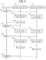
FIG. 3 is a sequence diagram illustrating an example of operations of an electricity storage system according to a second embodiment of the present disclosure. - Depending on the contract between a consumer facility and an electric power provider, the power from a storage cell that is not using renewable energy might not be allowed to flow in reverse to the power grid (i.e. to the electric power provider). In this case, a current sensor for detecting the current between the power grid and an electricity storage apparatus that includes the storage cell is installed in the electricity storage apparatus to prevent reverse power flow from the electricity storage apparatus to the power grid when the electricity storage apparatus is connected to the power grid. The electricity storage apparatus performs charging and discharging control of the storage cell so that a predetermined forward power flow (current flowing from the power grid toward the consumer facility) passes through the current sensor to prevent reverse power flow to the power grid. When, for example, the current flowing through the current sensor is smaller than a predetermined forward power flow, the electricity storage apparatus suspends power discharge to prevent reverse power flow. When, for example, the current flowing through the current sensor is greater than a predetermined forward power flow, the electricity storage apparatus discharges electric power from the storage cell and supplies the electric power to a load, such as an electrical device in the consumer facility.
- When a plurality of electricity storage apparatuses are connected between the power grid and the load and are operated in parallel, a respective current sensor is installed in each electricity storage apparatus. Each electricity storage apparatus controls the charging and discharging of the storage cell in the electricity storage apparatus so that a predetermined forward power flow passes through the respective current sensor. At this time, depending on the arrangement of the current sensor of the electricity storage apparatus, for example, charging and discharging by the electricity storage apparatus towards the load side tends to be prioritized. For example, suppose that the electricity storage apparatus provided towards the load side controls the charging and discharging of the storage cell in the electricity storage apparatus so that a predetermined forward power flow passes through the respective current sensor. The current sensor of the electricity storage apparatus provided on the power grid side then detects the predetermined forward power flow that has already been controlled by the electricity storage apparatus towards the load side. The electricity storage apparatus on the power grid side therefore ceases to discharge the storage cell. Consequently, the further the storage cell of the electricity storage apparatus is provided towards the load side, the greater the number of times the storage cell repeatedly charges and discharges.
- The storage cell tends to degrade faster as the number of times that charging and discharging is repeated increases. For example, when electricity storage apparatuses provided towards the load side are charged and discharged on a priority basis, degradation may proceed faster for the storage cell of the electricity storage apparatus that is provided further towards the load side. In this way, when a plurality of electricity storage apparatuses are operated in parallel, providing current sensors to prevent reverse power flow might cause an uneven degree of degradation among the storage cells.
- A first embodiment of the present disclosure is first described. The predetermined forward power flow that serves as the basis for determining whether to discharge a storage cell during control to prevent reverse power flow from the above-described storage cell to the power grid is referred to below as a forward power flow threshold. In the first embodiment, the forward power flow threshold is described as being 0 W, but values other than 0 W may also be used as the forward power flow threshold.
- As illustrated in
FIG. 1 , the electricity storage system 1 according to the first embodiment of the present disclosure includes current sensors (detectors) 10, 11 andelectricity storage apparatuses power grid 70, and supplies electric power to aload 80. Theload 80, which is an electrical device, for example, consumes the electric power supplied by the electricity storage system 1 and thepower grid 70. The electricity storage system 1 illustrated inFIG. 1 includes twoelectricity storage apparatuses FIG. 1 indicate power lines. The dashed lines inFIG. 1 indicate control lines and signal lines. The connections indicated by the control lines and signal lines may be wired connections or wireless connections. -
Current sensors power grid 70. InFIG. 1 , thecurrent sensors power grid 70 and theelectricity storage apparatus 20. Thecurrent sensors power grid 70 or of reverse power flow to thepower grid 70 and transmit the detected value to the respectiveelectricity storage apparatuses -
FIG. 1 illustrates an example in which twocurrent sensors power grid 70 and theelectricity storage apparatus 20, but the number of current sensors provided between thepower grid 70 and theelectricity storage apparatus 20 may be one. When only one current sensor is provided between thepower grid 70 and theelectricity storage apparatus 20, the current sensor transmits the detected values to theelectricity storage apparatuses - The
electricity storage apparatuses power grid 70, supply electric power to theload 80. Theelectricity storage apparatus 20 includes apower converter 30, astorage cell 40, amemory 50, and apower controller 60. Theelectricity storage apparatus 21 includes apower converter 31, astorage cell 41, amemory 51, and apower controller 61. - When discharging the
storage cells power controllers power converters storage cells load 80. On the basis of control by thepower controllers power converters power grid 70 to DC power and supply the DC power to thestorage cells storage cells - The
power controllers storage cells power converters storage cells power controllers storage cells storage cells power controllers - The
storage cells power converters storage cells power grid 70. Thestorage cells storage cells - The
memories respective storage cells respective power controllers storage cells - The processing to set the condition for the
power controllers storage cells - In the first embodiment, the condition for starting discharge is a standby time from detection of forward power flow by the
current sensors storage cells storage cells storage cells storage cells storage cells storage cells storage cells storage cells storage cells power controller 60 as an example. - When, for example, the
power controller 60 sets the standby time on the basis of the charge state of thestorage cell 40, thepower controller 60 refers to the charge state of thestorage cell 40 stored in thememory 50 and sets the standby time of thestorage cell 40 to be shorter as the charge state is "better". A good charge state means that the charge ratio (the remaining charge vs. the full charge) is high. When, for example, thepower controller 60 sets the standby time on the basis of the number of charges and discharges of thestorage cell 40, thepower controller 60 refers to the number of charges and discharges of thestorage cell 40 stored in thememory 50 and sets the standby time of thestorage cell 40 to be shorter as the number of charges and discharges is lower. When thepower controller 60 sets the standby time on the basis of the elapsed time since the previous discharge of thestorage cell 40, thepower controller 60 refers to the elapsed time of thestorage cell 40 stored in thememory 50 and sets the standby time of thestorage cell 40 to be shorter as the elapsed time is longer. When thepower controller 60 sets the standby time on the basis of the total charging and discharging time of thestorage cell 40, thepower controller 60 refers to the total charging and discharging time of thestorage cell 40 stored in thememory 50 and sets the standby time of thestorage cell 40 to be shorter as the total charging and discharging time is shorter. - The
power controller 60 may, for example, use a combination of two or more of the charge state of thestorage cell 40, the number of charges and discharges of thestorage cell 40, the elapsed time since the previous discharge of thestorage cell 40, and the total charging and discharging time of thestorage cell 40 to set the standby time. When, for example, thepower controller 60 sets the standby time by a combination of the charge state and the number of charges and discharges of thestorage cell 40, thepower controller 60 appropriately weights the standby time set on the basis of the charge state and the standby time set on the basis of the number of charges and discharges. Thepower controller 60 then calculates the standby time by totaling the results of the weighting. - The
power controller 60 periodically sets the above-described standby time. - The
power controllers current sensors power controllers respective storage cells - The standby times may be set by the
power controllers power controllers - Operations of the electricity storage system 1 according to the first embodiment are described below.
- It is assumed below that the standby time of the
electricity storage apparatus 20 is set to 5 seconds by the above-described processing by thepower controllers storage cells 40, 41 (in other words, the usage frequency of thestorage cell 40 is lower than the usage frequency of the storage cell 41). The standby time of theelectricity storage apparatus 21 is assumed to be set to 10 seconds. InFIG. 2 , the forward power flow is represented in watts [W], but a person skilled in the art can appropriately measure and convert the current/power. For example, thepower controllers current sensors - The power consumption of the
load 80 increases, and forward power flow passes through thecurrent sensors current sensors electricity storage apparatuses - Subsequently, the
power controllers electricity storage apparatuses power grid 70 on the basis of the values acquired from the respectivecurrent sensors 10, 11 (steps S102, S103). Theelectricity storage apparatus 20 then stands by for 5 seconds (step S104). Theelectricity storage apparatus 21 stands by for 10 seconds (step S105). - Once 5 seconds have passed from the processing in step S104, the
power controller 60 of theelectricity storage apparatus 20 starts discharge of thestorage cell 40 of the electricity storage apparatus 20 (step S106) and supplies electric power to theload 80. - The
current sensors electricity storage apparatuses current sensors - Subsequently, the
power controller 60 of theelectricity storage apparatus 20 detects, on the basis of the 0 W value acquired via thecurrent sensor 10, that the power consumption of theload 80 and the power supplied by theelectricity storage apparatus 20 are balanced (step S108). Similarly, thepower controller 61 of theelectricity storage apparatus 21 detects, on the basis of the 0 W value acquired via thecurrent sensor 11, that the power consumption of theload 80 and the power supplied by theelectricity storage apparatus 21 are balanced (step S109). - In this way, according to the processing in steps S101 to S109, electric power is supplied on a priority basis from the
electricity storage apparatus 20, for which the standby time is set to the shorter value of 5 seconds, when the power consumption of theload 80 can be covered by the power supply from one of theelectricity storage apparatuses - Subsequently, the power consumption of the
load 80 increases further, and forward power flow again passes through thecurrent sensors current sensors electricity storage apparatuses - Subsequently, the
power controllers electricity storage apparatuses power grid 70 on the basis of the values acquired from the respectivecurrent sensors 10, 11 (steps S111, S112). Theelectricity storage apparatus 20 then stands by for 5 seconds (step S113). Theelectricity storage apparatus 21 stands by for 10 seconds (step S114). - Once 5 seconds have passed from the processing in step S113, the
power controller 60 of theelectricity storage apparatus 20 starts discharge of thestorage cell 40 of the electricity storage apparatus 20 (step S115) and supplies electric power to theload 80. - Once 10 seconds have passed from the processing in step S114, the
power controller 61 of theelectricity storage apparatus 21 starts discharge of thestorage cell 41 of the electricity storage apparatus 21 (step S116) and supplies electric power to theload 80. - The
current sensors electricity storage apparatuses current sensors - As a result of the processing in steps S110 to S117, electric power is supplied to the
load 80 by both of theelectricity storage apparatuses load 80 is large. At this time, thestorage cell 41, which has a high usage frequency, is discharged after discharging thestorage cell 40, which has a low usage frequency. The amount of power discharged from thestorage cell 41, which has a high usage frequency, can thereby be reduced, reducing the depth of discharge of thestorage cell 41. Consequently, the progress of degradation of thestorage cell 41, which has a high usage frequency, can be slowed. - In the electricity storage system 1 according to the first embodiment, the standby time until discharge is started is thus set, on the basis of the state of the
storage cells storage cell 40 is lower, without using other apparatuses or the like. Consequently, in the electricity storage system 1, thestorage cell 40 with a low usage frequency is used first, allowing the degree of degradation of theelectricity storage apparatuses - Furthermore, even if a new electricity storage apparatus is added to the electricity storage system 1, the new electricity storage apparatus with a low usage frequency is used first in the electricity storage system 1 according to the above-described processing. The degree of degradation of the electricity storage apparatuses in the electricity storage system 1 can therefore be made uniform even when a new electricity storage apparatus is added to the electricity storage system 1.
- In the electricity storage system 1 according to the first embodiment, the above-described processing is performed by the
electricity storage apparatuses - In the second embodiment, the condition for the start of discharge is a forward power flow threshold for starting discharge of a storage cell, and an electricity storage apparatus that discharges electric power on a priority basis is set in accordance with this forward power flow threshold.
- An electricity storage system according to the second embodiment can adopt a similar configuration to that of the electricity storage system 1 according to the first embodiment. Therefore, the main differences with respect to the first embodiment are described below with reference to
FIG. 1 . - In the second embodiment, the usage frequency of the
storage cells storage cells storage cells storage cells storage cells storage cells storage cells storage cells power controller 60 as an example. - When, for example, the
power controller 60 sets the forward power flow threshold on the basis of the charge state of thestorage cell 40, thepower controller 60 refers to the charge state of thestorage cell 40 stored in thememory 50 and sets the forward power flow threshold of thestorage cell 40 to be lower as the charge state is higher. When, for example, thepower controller 60 sets the forward power flow threshold on the basis of the number of charges and discharges of thestorage cell 40, thepower controller 60 refers to the number of charges and discharges of thestorage cell 40 stored in thememory 50 and sets the forward power flow threshold of thestorage cell 40 to be lower as the number of charges and discharges is lower. When thepower controller 60 sets the forward power flow threshold on the basis of the elapsed time since the previous discharge of thestorage cell 40, thepower controller 60 refers to the elapsed time of thestorage cell 40 stored in thememory 50 and sets the forward power flow threshold of thestorage cell 40 to be lower as the elapsed time is longer. When thepower controller 60 sets the forward power flow threshold on the basis of the total charging and discharging time of thestorage cell 40, thepower controller 60 refers to the total charging and discharging time of thestorage cell 40 stored in thememory 50 and sets the forward power flow threshold of thestorage cell 40 to be lower as the total charging and discharging time is shorter. - The
power controller 60 may, for example, use a combination of two or more of the charge state of thestorage cell 40, the number of charges and discharges of thestorage cell 40, the elapsed time since the previous discharge of thestorage cell 40, and the total charging and discharging time of thestorage cell 40 to set the forward power flow threshold. When, for example, thepower controller 60 sets the forward power flow threshold by a combination of the charge state and the number of charges and discharges of thestorage cell 40, thepower controller 60 first appropriately weights the forward power flow threshold set on the basis of the charge state and the forward power flow threshold set on the basis of the number of charges and discharges. Thepower controller 60 then calculates the forward power flow threshold by totaling the results of the weighting. - The
power controller 60 periodically sets the above-described forward power flow threshold. - The
power controllers respective storage cells current sensors power controllers respective storage cells current sensors - The forward power flow thresholds may be set by the
power controllers - Operations of the electricity storage system 1 according to the second embodiment are described below with reference to
FIG. 3 . - In
FIG. 3 , the forward power flow and the forward power flow threshold are represented in watts [W], but a person skilled in the art can appropriately measure and convert the current/power. Furthermore, it is assumed below that the forward power flow threshold of theelectricity storage apparatus 20 is set to 70 W and the forward power flow threshold of theelectricity storage apparatus 21 is set to 100 W by the above-described processing by thepower controllers storage cells power controllers current sensors - The power consumption of the
load 80 increases, and forward power flow of 80 W passes through thecurrent sensors current sensors electricity storage apparatuses - Subsequently, the
power controller 60 of theelectricity storage apparatus 20 detects that the 80 W forward power flow acquired via thecurrent sensor 10 is greater than the 70 W forward power flow threshold of the electricity storage apparatus 20 (step S202) and starts discharge of the storage cell 40 (step S204). Thepower controller 61 of theelectricity storage apparatus 21 detects that the 80 W forward power flow acquired via thecurrent sensor 11 is less than the 100 W forward power flow threshold of the electricity storage apparatus 21 (step S203) and therefore does not discharge thestorage cell 41. - As a result of the processing in step S204, a forward power flow of 68 W passes through the
current sensors current sensors electricity storage apparatuses - Subsequently, the
power controllers electricity storage apparatuses current sensor 10 is less than the 70 W and 100 W forward power flow thresholds of the respectiveelectricity storage apparatuses 20, 21 (steps S206, S207). As a result, thestorage cells - In this way, by the processing in steps S201 to S207, electric power is supplied on a priority basis from the
electricity storage apparatus 20, for which the forward power flow threshold is set to the lower value of 70 W, when the power consumption of theload 80 can be covered by the power supply from one of theelectricity storage apparatuses - Subsequently, the power consumption of the
load 80 increases further, and a forward power flow of 200 W passes through thecurrent sensors current sensors electricity storage apparatuses - Subsequently, the
power controller 60 of theelectricity storage apparatus 20 detects that the 200 W forward power flow acquired via thecurrent sensor 10 is greater than the 70 W forward power flow threshold of the electricity storage apparatus 20 (step S209) and starts discharge of the storage cell 40 (step S211). Thepower controller 61 of theelectricity storage apparatus 21 also detects that the 200 W forward power flow acquired via thecurrent sensor 10 is greater than the 100 W forward power flow threshold of the electricity storage apparatus 21 (step S210) and starts discharge of the storage cell 41 (step S212). - As a result of the processing in steps S211 and S212, a forward power flow of 68 W passes through the
current sensors current sensors electricity storage apparatuses - As a result of the processing in steps S208 to S213, electric power is supplied to the
load 80 by both of theelectricity storage apparatuses load 80 is large. - In the electricity storage system 1 according to the second embodiment, the forward power flow threshold for starting discharge is thus set on the basis of the state of the
storage cells storage cells storage cell 40 with a low usage frequency is used first, allowing the degree of degradation of theelectricity storage apparatuses - The other effects of the second embodiment are similar to those of the first embodiment.
- The case in which, depending on the contract between a consumer facility and an electric power provider, the power of an electricity storage apparatus, a fuel cell apparatus, or the like that is not using renewable energy is prohibited from flowing in reverse to the power grid (i.e. to the electric power provider) has been described above. However, the present embodiment can also be applied to the case in which power from an electricity storage apparatus, a fuel cell apparatus, and the like is allowed to flow in reverse to the power grid (i.e. to the electric power provider).
- Although embodiments of the present disclosure have been described on the basis of drawings and examples, it is to be noted that various changes and modifications will be apparent to those skilled in the art based on the present disclosure. Therefore, such changes and modifications are to be understood as included within the scope of the present disclosure. For example, the functions and the like included in the various components and steps may be reordered in any logically consistent way. Furthermore, components or steps may be combined into one or divided.
- The control of the present disclosure is described as a series of operations executed by a computer system and other hardware that can execute program instructions. Examples of the computer system and other hardware include a general-purpose computer, a personal computer (PC), a dedicated computer, a workstation, and other programmable data processing apparatuses. It should be noted that in each embodiment, various operations may be executed by a dedicated circuit (for example, individual logical gates interconnected in order to execute a particular function) implemented by program instructions (software). It should also be noted that various operations may be executed by a logical block, program module, or the like executed by one or more processors. The one or more processors that execute a logical block, program module, or the like encompass, for example, one or more of a microprocessor, a central processing unit (CPU), and a digital signal processor (DSP). The one or more processors also, for example, encompass an application specific integrated circuit (ASIC), a programmable logic device (PLD), and a field programmable gate array (FPGA). The one or more processors also, for example, encompass a controller, a microcontroller, an electronic device, another apparatus designed to be capable of executing the functions disclosed herein, and/or a combination of any of the above. The embodiments disclosed herein are, for example, implemented by hardware, software, firmware, middleware, microcode, or a combination of any of these.
- The network used here may, unless indicated otherwise, be the Internet, an ad hoc network, a local area network (LAN), a cellular network, another network, or a combination of any of these.
-
- 1
- Electricity storage system
- 10, 11
- Current sensor (detector)
- 20, 21
- Electricity storage apparatus
- 30, 31
- Power converter
- 40, 41
- Storage cell
- 50, 51
- Memory
- 60, 61
- Power controller
- 70
- Power grid
- 80
- Load
Claims (15)
- An electricity storage system comprising:a plurality of electricity storage apparatuses configured to connect to a power grid and supply power to a load; anda detector configured to detect a forward power flow from the power grid;wherein the plurality of electricity storage apparatuses comprises:a plurality of storage cells configured to be charged using electric power supplied by the power grid; anda plurality of power controllers configured to control charging and discharging of respective storage cells in the plurality of storage cells; andwherein each of the plurality of power controllers sets a condition for starting discharge of each of the plurality of storage cells on the basis of a state of each of the plurality of storage cells.
- The electricity storage system of claim 1, wherein the condition is a standby time from detection of forward power flow until starting discharge of the storage cell.
- The electricity storage system of claim 2, wherein the state of each of the plurality of storage cells is a charge state of each of the plurality of storage cells, and the plurality of power controllers sets the standby time to be shorter as the charge state is better.
- The electricity storage system of claim 2, wherein the state of each of the plurality of storage cells is a number of charges and discharges of each of the plurality of storage cells, and the plurality of power controllers sets the standby time to be shorter as the number of charges and discharges is smaller.
- The electricity storage system of claim 2, wherein the state of each of the plurality of storage cells is an elapsed time since a previous discharge of each of the plurality of storage cells, and the plurality of power controllers sets the standby time to be shorter as the elapsed time is longer.
- The electricity storage system of claim 2, wherein the state of each of the plurality of storage cells is a total charging and discharging time of each of the plurality of storage cells, and the plurality of power controllers sets the standby time to be shorter as the total charging and discharging time is shorter.
- The electricity storage system of claim 2, wherein the state of each of the plurality of storage cells is a combination of two or more of a charge state of each of the plurality of storage cells, a number of charges and discharges of each of the plurality of storage cells, an elapsed time since a previous discharge of each of the plurality of storage cells, and a total charging and discharging time of each of the plurality of storage cells, and the plurality of power controllers sets the standby time on the basis of the combination.
- The electricity storage system of claim 1, wherein the condition is a forward power flow threshold for starting discharge of each of the plurality of storage cells.
- The electricity storage system of claim 8, wherein the state of each of the plurality of storage cells is a charge state of each of the plurality of storage cells, and the plurality of power controllers sets the forward power flow threshold to be lower as the charge state is higher.
- The electricity storage system of claim 8, wherein the state of each of the plurality of storage cells is a number of charges and discharges of each of the plurality of storage cells, and the plurality of power controllers sets the forward power flow threshold to be lower as the number of charges and discharges is smaller.
- The electricity storage system of claim 8, wherein the state of each of the plurality of storage cells is an elapsed time since a previous discharge of each of the plurality of storage cells, and the plurality of power controllers sets the forward power flow threshold to be lower as the elapsed time is longer.
- The electricity storage system of claim 8, wherein the state of each of the plurality of storage cells is a total charging and discharging time of each of the plurality of storage cells, and the plurality of power controllers sets the forward power flow threshold to be lower as the total charging and discharging time is shorter.
- The electricity storage system of claim 8, wherein the state of each of the plurality of storage cells is a combination of two or more of a charge state of each of the plurality of storage cells, a number of charges and discharges of each of the plurality of storage cells, an elapsed time since a previous discharge of each of the plurality of storage cells, and a total charging and discharging time of each of the plurality of storage cells, and the plurality of power controllers sets the forward power flow threshold on the basis of the combination.
- An electricity storage apparatus configured to connect to a power grid and supply electric power to a load, the electricity storage apparatus comprising:a storage cell configured to supply electric power to the load by discharging; anda power controller configured to control charging and discharging of the storage cell;wherein the power controller sets a condition for starting discharge of the storage cell on the basis of a state of the storage cell.
- A control method of an electricity storage system comprising a plurality of electricity storage apparatuses and a detector configured to detect a forward power flow from a power grid, each electricity storage apparatus including a storage cell, the control method comprising:setting a condition for starting discharge of each storage cell on the basis of a state of each storage cell; anddischarging electric power from each storage cell in accordance with the condition upon detecting forward power flow from the detector.
Applications Claiming Priority (2)
| Application Number | Priority Date | Filing Date | Title |
|---|---|---|---|
| JP2015192188 | 2015-09-29 | ||
| PCT/JP2016/004405 WO2017056503A1 (en) | 2015-09-29 | 2016-09-29 | Electricity storage system, electricity storage device, and electricity storage system control method |
Publications (3)
| Publication Number | Publication Date |
|---|---|
| EP3358696A1 true EP3358696A1 (en) | 2018-08-08 |
| EP3358696A4 EP3358696A4 (en) | 2019-03-13 |
| EP3358696B1 EP3358696B1 (en) | 2020-05-06 |
Family
ID=58423060
Family Applications (1)
| Application Number | Title | Priority Date | Filing Date |
|---|---|---|---|
| EP16850681.4A Active EP3358696B1 (en) | 2015-09-29 | 2016-09-29 | Electricity storage system, electricity storage device, and electricity storage system control method |
Country Status (4)
| Country | Link |
|---|---|
| US (1) | US10637106B2 (en) |
| EP (1) | EP3358696B1 (en) |
| JP (1) | JP6559247B2 (en) |
| WO (1) | WO2017056503A1 (en) |
Families Citing this family (9)
| Publication number | Priority date | Publication date | Assignee | Title |
|---|---|---|---|---|
| JP6706843B2 (en) * | 2016-07-29 | 2020-06-10 | パナソニックIpマネジメント株式会社 | Power supply system and power converter |
| JP7064330B2 (en) * | 2017-12-27 | 2022-05-10 | 大和ハウス工業株式会社 | Power supply system |
| JP6981369B2 (en) * | 2018-06-06 | 2021-12-15 | 住友電気工業株式会社 | Power storage system |
| CN114830486A (en) * | 2019-12-13 | 2022-07-29 | 京瓷株式会社 | Power storage device and power storage method |
| DE102020100008A1 (en) * | 2020-01-02 | 2021-07-08 | Innogy Se | Electrical supply system for a building |
| US12191659B2 (en) * | 2021-05-10 | 2025-01-07 | Electronics And Telecommunications Research Institute | Method for controlling energy storage system and devices performing method |
| CN114498808A (en) * | 2021-12-08 | 2022-05-13 | 华为技术有限公司 | Power supply system and related method |
| WO2023210327A1 (en) * | 2022-04-27 | 2023-11-02 | 京セラ株式会社 | Electricity storage system, and control method |
| JP7797316B2 (en) * | 2022-06-21 | 2026-01-13 | 東芝エネルギーシステムズ株式会社 | Reverse flow power control device and reverse flow power control method |
Family Cites Families (7)
| Publication number | Priority date | Publication date | Assignee | Title |
|---|---|---|---|---|
| JP4850019B2 (en) * | 2006-10-16 | 2012-01-11 | 東京瓦斯株式会社 | Storage battery equipment in private power generation equipment connected to power system and operation method of storage battery equipment |
| JP5618393B2 (en) | 2011-03-25 | 2014-11-05 | Necエナジーデバイス株式会社 | Power storage system and secondary battery control method |
| JP5924524B2 (en) * | 2012-03-13 | 2016-05-25 | オムロン株式会社 | Storage battery control device, storage battery control method, program, power storage system, and power supply system |
| US9793723B2 (en) * | 2012-11-19 | 2017-10-17 | Hitachi, Ltd. | Storage battery control device and storage battery control method |
| JP2014128152A (en) * | 2012-12-27 | 2014-07-07 | Panasonic Corp | Charge and discharge controller, charge and discharge control system and charge and discharge control method |
| JP2015106962A (en) * | 2013-11-29 | 2015-06-08 | 株式会社デンソー | Charge discharge controller and charge discharge system |
| JP2016025732A (en) * | 2014-07-18 | 2016-02-08 | ニチコン株式会社 | Power supply system, and control method and control program for the same |
-
2016
- 2016-09-29 JP JP2017542758A patent/JP6559247B2/en active Active
- 2016-09-29 EP EP16850681.4A patent/EP3358696B1/en active Active
- 2016-09-29 WO PCT/JP2016/004405 patent/WO2017056503A1/en not_active Ceased
- 2016-09-29 US US15/763,413 patent/US10637106B2/en active Active
Also Published As
| Publication number | Publication date |
|---|---|
| JPWO2017056503A1 (en) | 2018-03-15 |
| US10637106B2 (en) | 2020-04-28 |
| EP3358696B1 (en) | 2020-05-06 |
| EP3358696A4 (en) | 2019-03-13 |
| JP6559247B2 (en) | 2019-08-14 |
| US20180287217A1 (en) | 2018-10-04 |
| WO2017056503A1 (en) | 2017-04-06 |
Similar Documents
| Publication | Publication Date | Title |
|---|---|---|
| EP3358696B1 (en) | Electricity storage system, electricity storage device, and electricity storage system control method | |
| EP3961233A1 (en) | Battery cell diagnosis device and method | |
| US9787118B2 (en) | Simple and high efficiency balancing circuits and methods for hybrid batteries | |
| CN104242397B (en) | More Quick charge circuit for battery and its charging method | |
| US10031185B2 (en) | Method for determining a state of charge and remaining operation life of a battery | |
| KR102782821B1 (en) | Battery management apparatus, battery pack, energy storage system, and battery management method | |
| KR20160095524A (en) | Battery pack and controlling method thereof | |
| KR20140065951A (en) | Battery management system and driving method thereof | |
| JPWO2016051722A1 (en) | Power storage device, control device, power storage system, power storage device control method and control program | |
| KR101177455B1 (en) | Battery charging apparatus, battery pack, battery charging system and battery charging method | |
| Hussein et al. | Design considerations and performance evaluation of outdoor PV battery chargers | |
| EP3379677B1 (en) | Received power control device and received power control method | |
| CN115833210A (en) | A multi-machine parallel energy storage system and its charging and discharging control method | |
| CN107005069B (en) | Battery charging method and apparatus utilizing power point checking and switchable control | |
| KR20180049545A (en) | Battery pack with multi-charging function and energy storage system considered extensibility of battery pack | |
| EP3358695B1 (en) | Power source device, distributed power source system, and control method thereof | |
| CN116819335A (en) | Battery life prediction method, device, computer equipment and storage medium | |
| KR20180049543A (en) | Energy storage system considered extensibility of battery pack and method for controlling therefor | |
| CN110809845B (en) | Battery components | |
| CN118677009A (en) | Equipment control method, inverter and computer readable storage medium | |
| CN111758201A (en) | Electronic equipment | |
| JP6831790B2 (en) | Wake up the charger of the energy storage system | |
| JP6544247B2 (en) | Charging device, charging device control program and method thereof | |
| KR102961140B1 (en) | Battery management apparatus and method |
Legal Events
| Date | Code | Title | Description |
|---|---|---|---|
| STAA | Information on the status of an ep patent application or granted ep patent |
Free format text: STATUS: THE INTERNATIONAL PUBLICATION HAS BEEN MADE |
|
| PUAI | Public reference made under article 153(3) epc to a published international application that has entered the european phase |
Free format text: ORIGINAL CODE: 0009012 |
|
| STAA | Information on the status of an ep patent application or granted ep patent |
Free format text: STATUS: REQUEST FOR EXAMINATION WAS MADE |
|
| 17P | Request for examination filed |
Effective date: 20180329 |
|
| AK | Designated contracting states |
Kind code of ref document: A1 Designated state(s): AL AT BE BG CH CY CZ DE DK EE ES FI FR GB GR HR HU IE IS IT LI LT LU LV MC MK MT NL NO PL PT RO RS SE SI SK SM TR |
|
| AX | Request for extension of the european patent |
Extension state: BA ME |
|
| DAV | Request for validation of the european patent (deleted) | ||
| DAX | Request for extension of the european patent (deleted) | ||
| A4 | Supplementary search report drawn up and despatched |
Effective date: 20190212 |
|
| RIC1 | Information provided on ipc code assigned before grant |
Ipc: H01M 10/48 20060101ALI20190206BHEP Ipc: H01M 10/44 20060101ALI20190206BHEP Ipc: H02J 7/34 20060101ALN20190206BHEP Ipc: H02J 7/00 20060101ALI20190206BHEP Ipc: H01M 10/42 20060101ALI20190206BHEP Ipc: H02J 3/32 20060101AFI20190206BHEP Ipc: H02J 3/38 20060101ALN20190206BHEP |
|
| REG | Reference to a national code |
Ref country code: DE Ref legal event code: R079 Ref document number: 602016036134 Country of ref document: DE Free format text: PREVIOUS MAIN CLASS: H02J0007000000 Ipc: H02J0003320000 |
|
| GRAP | Despatch of communication of intention to grant a patent |
Free format text: ORIGINAL CODE: EPIDOSNIGR1 |
|
| STAA | Information on the status of an ep patent application or granted ep patent |
Free format text: STATUS: GRANT OF PATENT IS INTENDED |
|
| RIC1 | Information provided on ipc code assigned before grant |
Ipc: H02J 7/00 20060101ALI20191120BHEP Ipc: H02J 3/38 20060101ALN20191120BHEP Ipc: H01M 10/48 20060101ALI20191120BHEP Ipc: H01M 10/44 20060101ALI20191120BHEP Ipc: H01M 10/42 20060101ALI20191120BHEP Ipc: H02J 3/32 20060101AFI20191120BHEP Ipc: H02J 7/34 20060101ALN20191120BHEP |
|
| RIC1 | Information provided on ipc code assigned before grant |
Ipc: H01M 10/44 20060101ALI20191126BHEP Ipc: H02J 7/00 20060101ALI20191126BHEP Ipc: H01M 10/48 20060101ALI20191126BHEP Ipc: H01M 10/42 20060101ALI20191126BHEP Ipc: H02J 3/32 20060101AFI20191126BHEP Ipc: H02J 3/38 20060101ALN20191126BHEP Ipc: H02J 7/34 20060101ALN20191126BHEP |
|
| RIN1 | Information on inventor provided before grant (corrected) |
Inventor name: TAKENAKA, TETSUYA |
|
| INTG | Intention to grant announced |
Effective date: 20191209 |
|
| GRAS | Grant fee paid |
Free format text: ORIGINAL CODE: EPIDOSNIGR3 |
|
| GRAA | (expected) grant |
Free format text: ORIGINAL CODE: 0009210 |
|
| STAA | Information on the status of an ep patent application or granted ep patent |
Free format text: STATUS: THE PATENT HAS BEEN GRANTED |
|
| AK | Designated contracting states |
Kind code of ref document: B1 Designated state(s): AL AT BE BG CH CY CZ DE DK EE ES FI FR GB GR HR HU IE IS IT LI LT LU LV MC MK MT NL NO PL PT RO RS SE SI SK SM TR |
|
| REG | Reference to a national code |
Ref country code: GB Ref legal event code: FG4D |
|
| REG | Reference to a national code |
Ref country code: CH Ref legal event code: EP Ref country code: AT Ref legal event code: REF Ref document number: 1268375 Country of ref document: AT Kind code of ref document: T Effective date: 20200515 |
|
| REG | Reference to a national code |
Ref country code: IE Ref legal event code: FG4D |
|
| REG | Reference to a national code |
Ref country code: DE Ref legal event code: R096 Ref document number: 602016036134 Country of ref document: DE |
|
| REG | Reference to a national code |
Ref country code: LT Ref legal event code: MG4D |
|
| REG | Reference to a national code |
Ref country code: NL Ref legal event code: MP Effective date: 20200506 |
|
| PG25 | Lapsed in a contracting state [announced via postgrant information from national office to epo] |
Ref country code: GR Free format text: LAPSE BECAUSE OF FAILURE TO SUBMIT A TRANSLATION OF THE DESCRIPTION OR TO PAY THE FEE WITHIN THE PRESCRIBED TIME-LIMIT Effective date: 20200807 Ref country code: NO Free format text: LAPSE BECAUSE OF FAILURE TO SUBMIT A TRANSLATION OF THE DESCRIPTION OR TO PAY THE FEE WITHIN THE PRESCRIBED TIME-LIMIT Effective date: 20200806 Ref country code: PT Free format text: LAPSE BECAUSE OF FAILURE TO SUBMIT A TRANSLATION OF THE DESCRIPTION OR TO PAY THE FEE WITHIN THE PRESCRIBED TIME-LIMIT Effective date: 20200907 Ref country code: SE Free format text: LAPSE BECAUSE OF FAILURE TO SUBMIT A TRANSLATION OF THE DESCRIPTION OR TO PAY THE FEE WITHIN THE PRESCRIBED TIME-LIMIT Effective date: 20200506 Ref country code: IS Free format text: LAPSE BECAUSE OF FAILURE TO SUBMIT A TRANSLATION OF THE DESCRIPTION OR TO PAY THE FEE WITHIN THE PRESCRIBED TIME-LIMIT Effective date: 20200906 Ref country code: FI Free format text: LAPSE BECAUSE OF FAILURE TO SUBMIT A TRANSLATION OF THE DESCRIPTION OR TO PAY THE FEE WITHIN THE PRESCRIBED TIME-LIMIT Effective date: 20200506 Ref country code: LT Free format text: LAPSE BECAUSE OF FAILURE TO SUBMIT A TRANSLATION OF THE DESCRIPTION OR TO PAY THE FEE WITHIN THE PRESCRIBED TIME-LIMIT Effective date: 20200506 |
|
| PG25 | Lapsed in a contracting state [announced via postgrant information from national office to epo] |
Ref country code: HR Free format text: LAPSE BECAUSE OF FAILURE TO SUBMIT A TRANSLATION OF THE DESCRIPTION OR TO PAY THE FEE WITHIN THE PRESCRIBED TIME-LIMIT Effective date: 20200506 Ref country code: LV Free format text: LAPSE BECAUSE OF FAILURE TO SUBMIT A TRANSLATION OF THE DESCRIPTION OR TO PAY THE FEE WITHIN THE PRESCRIBED TIME-LIMIT Effective date: 20200506 Ref country code: BG Free format text: LAPSE BECAUSE OF FAILURE TO SUBMIT A TRANSLATION OF THE DESCRIPTION OR TO PAY THE FEE WITHIN THE PRESCRIBED TIME-LIMIT Effective date: 20200806 Ref country code: RS Free format text: LAPSE BECAUSE OF FAILURE TO SUBMIT A TRANSLATION OF THE DESCRIPTION OR TO PAY THE FEE WITHIN THE PRESCRIBED TIME-LIMIT Effective date: 20200506 |
|
| REG | Reference to a national code |
Ref country code: AT Ref legal event code: MK05 Ref document number: 1268375 Country of ref document: AT Kind code of ref document: T Effective date: 20200506 |
|
| PG25 | Lapsed in a contracting state [announced via postgrant information from national office to epo] |
Ref country code: NL Free format text: LAPSE BECAUSE OF FAILURE TO SUBMIT A TRANSLATION OF THE DESCRIPTION OR TO PAY THE FEE WITHIN THE PRESCRIBED TIME-LIMIT Effective date: 20200506 Ref country code: AL Free format text: LAPSE BECAUSE OF FAILURE TO SUBMIT A TRANSLATION OF THE DESCRIPTION OR TO PAY THE FEE WITHIN THE PRESCRIBED TIME-LIMIT Effective date: 20200506 |
|
| PG25 | Lapsed in a contracting state [announced via postgrant information from national office to epo] |
Ref country code: ES Free format text: LAPSE BECAUSE OF FAILURE TO SUBMIT A TRANSLATION OF THE DESCRIPTION OR TO PAY THE FEE WITHIN THE PRESCRIBED TIME-LIMIT Effective date: 20200506 Ref country code: DK Free format text: LAPSE BECAUSE OF FAILURE TO SUBMIT A TRANSLATION OF THE DESCRIPTION OR TO PAY THE FEE WITHIN THE PRESCRIBED TIME-LIMIT Effective date: 20200506 Ref country code: AT Free format text: LAPSE BECAUSE OF FAILURE TO SUBMIT A TRANSLATION OF THE DESCRIPTION OR TO PAY THE FEE WITHIN THE PRESCRIBED TIME-LIMIT Effective date: 20200506 Ref country code: IT Free format text: LAPSE BECAUSE OF FAILURE TO SUBMIT A TRANSLATION OF THE DESCRIPTION OR TO PAY THE FEE WITHIN THE PRESCRIBED TIME-LIMIT Effective date: 20200506 Ref country code: SM Free format text: LAPSE BECAUSE OF FAILURE TO SUBMIT A TRANSLATION OF THE DESCRIPTION OR TO PAY THE FEE WITHIN THE PRESCRIBED TIME-LIMIT Effective date: 20200506 Ref country code: EE Free format text: LAPSE BECAUSE OF FAILURE TO SUBMIT A TRANSLATION OF THE DESCRIPTION OR TO PAY THE FEE WITHIN THE PRESCRIBED TIME-LIMIT Effective date: 20200506 Ref country code: CZ Free format text: LAPSE BECAUSE OF FAILURE TO SUBMIT A TRANSLATION OF THE DESCRIPTION OR TO PAY THE FEE WITHIN THE PRESCRIBED TIME-LIMIT Effective date: 20200506 Ref country code: RO Free format text: LAPSE BECAUSE OF FAILURE TO SUBMIT A TRANSLATION OF THE DESCRIPTION OR TO PAY THE FEE WITHIN THE PRESCRIBED TIME-LIMIT Effective date: 20200506 |
|
| REG | Reference to a national code |
Ref country code: DE Ref legal event code: R097 Ref document number: 602016036134 Country of ref document: DE |
|
| PG25 | Lapsed in a contracting state [announced via postgrant information from national office to epo] |
Ref country code: PL Free format text: LAPSE BECAUSE OF FAILURE TO SUBMIT A TRANSLATION OF THE DESCRIPTION OR TO PAY THE FEE WITHIN THE PRESCRIBED TIME-LIMIT Effective date: 20200506 Ref country code: SK Free format text: LAPSE BECAUSE OF FAILURE TO SUBMIT A TRANSLATION OF THE DESCRIPTION OR TO PAY THE FEE WITHIN THE PRESCRIBED TIME-LIMIT Effective date: 20200506 |
|
| PLBE | No opposition filed within time limit |
Free format text: ORIGINAL CODE: 0009261 |
|
| STAA | Information on the status of an ep patent application or granted ep patent |
Free format text: STATUS: NO OPPOSITION FILED WITHIN TIME LIMIT |
|
| 26N | No opposition filed |
Effective date: 20210209 |
|
| REG | Reference to a national code |
Ref country code: CH Ref legal event code: PL |
|
| GBPC | Gb: european patent ceased through non-payment of renewal fee |
Effective date: 20200929 |
|
| PG25 | Lapsed in a contracting state [announced via postgrant information from national office to epo] |
Ref country code: SI Free format text: LAPSE BECAUSE OF FAILURE TO SUBMIT A TRANSLATION OF THE DESCRIPTION OR TO PAY THE FEE WITHIN THE PRESCRIBED TIME-LIMIT Effective date: 20200506 |
|
| REG | Reference to a national code |
Ref country code: BE Ref legal event code: MM Effective date: 20200930 |
|
| PG25 | Lapsed in a contracting state [announced via postgrant information from national office to epo] |
Ref country code: LU Free format text: LAPSE BECAUSE OF NON-PAYMENT OF DUE FEES Effective date: 20200929 |
|
| PG25 | Lapsed in a contracting state [announced via postgrant information from national office to epo] |
Ref country code: FR Free format text: LAPSE BECAUSE OF NON-PAYMENT OF DUE FEES Effective date: 20200930 |
|
| PG25 | Lapsed in a contracting state [announced via postgrant information from national office to epo] |
Ref country code: IE Free format text: LAPSE BECAUSE OF NON-PAYMENT OF DUE FEES Effective date: 20200929 Ref country code: LI Free format text: LAPSE BECAUSE OF NON-PAYMENT OF DUE FEES Effective date: 20200930 Ref country code: GB Free format text: LAPSE BECAUSE OF NON-PAYMENT OF DUE FEES Effective date: 20200929 Ref country code: CH Free format text: LAPSE BECAUSE OF NON-PAYMENT OF DUE FEES Effective date: 20200930 Ref country code: BE Free format text: LAPSE BECAUSE OF NON-PAYMENT OF DUE FEES Effective date: 20200930 |
|
| PG25 | Lapsed in a contracting state [announced via postgrant information from national office to epo] |
Ref country code: TR Free format text: LAPSE BECAUSE OF FAILURE TO SUBMIT A TRANSLATION OF THE DESCRIPTION OR TO PAY THE FEE WITHIN THE PRESCRIBED TIME-LIMIT Effective date: 20200506 Ref country code: MT Free format text: LAPSE BECAUSE OF FAILURE TO SUBMIT A TRANSLATION OF THE DESCRIPTION OR TO PAY THE FEE WITHIN THE PRESCRIBED TIME-LIMIT Effective date: 20200506 Ref country code: CY Free format text: LAPSE BECAUSE OF FAILURE TO SUBMIT A TRANSLATION OF THE DESCRIPTION OR TO PAY THE FEE WITHIN THE PRESCRIBED TIME-LIMIT Effective date: 20200506 |
|
| PG25 | Lapsed in a contracting state [announced via postgrant information from national office to epo] |
Ref country code: MK Free format text: LAPSE BECAUSE OF FAILURE TO SUBMIT A TRANSLATION OF THE DESCRIPTION OR TO PAY THE FEE WITHIN THE PRESCRIBED TIME-LIMIT Effective date: 20200506 Ref country code: MC Free format text: LAPSE BECAUSE OF FAILURE TO SUBMIT A TRANSLATION OF THE DESCRIPTION OR TO PAY THE FEE WITHIN THE PRESCRIBED TIME-LIMIT Effective date: 20200506 |
|
| P01 | Opt-out of the competence of the unified patent court (upc) registered |
Effective date: 20230508 |
|
| PGFP | Annual fee paid to national office [announced via postgrant information from national office to epo] |
Ref country code: DE Payment date: 20240806 Year of fee payment: 9 |