EP3358691A1 - Arc detection apparatus - Google Patents
Arc detection apparatus Download PDFInfo
- Publication number
- EP3358691A1 EP3358691A1 EP17202104.0A EP17202104A EP3358691A1 EP 3358691 A1 EP3358691 A1 EP 3358691A1 EP 17202104 A EP17202104 A EP 17202104A EP 3358691 A1 EP3358691 A1 EP 3358691A1
- Authority
- EP
- European Patent Office
- Prior art keywords
- power
- optimizer
- capacitor
- impedance
- power lines
- Prior art date
- Legal status (The legal status is an assumption and is not a legal conclusion. Google has not performed a legal analysis and makes no representation as to the accuracy of the status listed.)
- Withdrawn
Links
Images




Classifications
-
- H—ELECTRICITY
- H02—GENERATION; CONVERSION OR DISTRIBUTION OF ELECTRIC POWER
- H02J—ELECTRIC POWER NETWORKS; CIRCUIT ARRANGEMENTS OR SYSTEMS FOR SUPPLYING OR DISTRIBUTING ELECTRIC POWER; SYSTEMS FOR STORING ELECTRIC ENERGY
- H02J3/00—Circuit arrangements for AC mains or AC distribution networks
- H02J3/38—Arrangements for feeding a single network from two or more generators or sources in parallel; Arrangements for feeding already energised networks from additional generators or sources in parallel
- H02J3/381—Dispersed generators
-
- G—PHYSICS
- G01—MEASURING; TESTING
- G01R—MEASURING ELECTRIC VARIABLES; MEASURING MAGNETIC VARIABLES
- G01R31/00—Arrangements for testing electric properties; Arrangements for locating electric faults; Arrangements for electrical testing characterised by what is being tested not provided for elsewhere
- G01R31/12—Testing dielectric strength or breakdown voltage ; Testing or monitoring effectiveness or level of insulation, e.g. of a cable or of an apparatus, for example using partial discharge measurements; Electrostatic testing
- G01R31/1227—Testing dielectric strength or breakdown voltage ; Testing or monitoring effectiveness or level of insulation, e.g. of a cable or of an apparatus, for example using partial discharge measurements; Electrostatic testing of components, parts or materials
- G01R31/1263—Testing dielectric strength or breakdown voltage ; Testing or monitoring effectiveness or level of insulation, e.g. of a cable or of an apparatus, for example using partial discharge measurements; Electrostatic testing of components, parts or materials of solid or fluid materials, e.g. insulation films, bulk material; of semiconductors or LV electronic components or parts; of cable, line or wire insulation
- G01R31/1272—Testing dielectric strength or breakdown voltage ; Testing or monitoring effectiveness or level of insulation, e.g. of a cable or of an apparatus, for example using partial discharge measurements; Electrostatic testing of components, parts or materials of solid or fluid materials, e.g. insulation films, bulk material; of semiconductors or LV electronic components or parts; of cable, line or wire insulation of cable, line or wire insulation, e.g. using partial discharge measurements
-
- H—ELECTRICITY
- H02—GENERATION; CONVERSION OR DISTRIBUTION OF ELECTRIC POWER
- H02H—EMERGENCY PROTECTIVE CIRCUIT ARRANGEMENTS
- H02H1/00—Details of emergency protective circuit arrangements
- H02H1/0007—Details of emergency protective circuit arrangements concerning the detecting means
- H02H1/0015—Using arc detectors
-
- H—ELECTRICITY
- H02—GENERATION; CONVERSION OR DISTRIBUTION OF ELECTRIC POWER
- H02S—GENERATION OF ELECTRIC POWER BY CONVERSION OF INFRARED RADIATION, VISIBLE LIGHT OR ULTRAVIOLET LIGHT, e.g. USING PHOTOVOLTAIC [PV] MODULES
- H02S50/00—Monitoring or testing of PV systems, e.g. load balancing or fault identification
- H02S50/10—Testing of PV devices, e.g. of PV modules or single PV cells
-
- H—ELECTRICITY
- H02—GENERATION; CONVERSION OR DISTRIBUTION OF ELECTRIC POWER
- H02H—EMERGENCY PROTECTIVE CIRCUIT ARRANGEMENTS
- H02H7/00—Emergency protective circuit arrangements specially adapted for specific types of electric machines or apparatus or for sectionalised protection of cable or line systems, and effecting automatic switching in the event of an undesired change from normal working conditions
- H02H7/26—Sectionalised protection of cable or line systems, e.g. for disconnecting a section on which a short-circuit, earth fault, or arc discharge has occured
- H02H7/268—Sectionalised protection of cable or line systems, e.g. for disconnecting a section on which a short-circuit, earth fault, or arc discharge has occured for DC systems
-
- H—ELECTRICITY
- H02—GENERATION; CONVERSION OR DISTRIBUTION OF ELECTRIC POWER
- H02J—ELECTRIC POWER NETWORKS; CIRCUIT ARRANGEMENTS OR SYSTEMS FOR SUPPLYING OR DISTRIBUTING ELECTRIC POWER; SYSTEMS FOR STORING ELECTRIC ENERGY
- H02J2101/00—Supply or distribution of decentralised, dispersed or local electric power generation
- H02J2101/20—Dispersed power generation using renewable energy sources
- H02J2101/22—Solar energy
- H02J2101/24—Photovoltaics
-
- H—ELECTRICITY
- H02—GENERATION; CONVERSION OR DISTRIBUTION OF ELECTRIC POWER
- H02J—ELECTRIC POWER NETWORKS; CIRCUIT ARRANGEMENTS OR SYSTEMS FOR SUPPLYING OR DISTRIBUTING ELECTRIC POWER; SYSTEMS FOR STORING ELECTRIC ENERGY
- H02J2101/00—Supply or distribution of decentralised, dispersed or local electric power generation
- H02J2101/20—Dispersed power generation using renewable energy sources
- H02J2101/22—Solar energy
- H02J2101/24—Photovoltaics
- H02J2101/25—Photovoltaics involving maximum power point tracking control for photovoltaic sources
-
- Y—GENERAL TAGGING OF NEW TECHNOLOGICAL DEVELOPMENTS; GENERAL TAGGING OF CROSS-SECTIONAL TECHNOLOGIES SPANNING OVER SEVERAL SECTIONS OF THE IPC; TECHNICAL SUBJECTS COVERED BY FORMER USPC CROSS-REFERENCE ART COLLECTIONS [XRACs] AND DIGESTS
- Y02—TECHNOLOGIES OR APPLICATIONS FOR MITIGATION OR ADAPTATION AGAINST CLIMATE CHANGE
- Y02E—REDUCTION OF GREENHOUSE GAS [GHG] EMISSIONS, RELATED TO ENERGY GENERATION, TRANSMISSION OR DISTRIBUTION
- Y02E10/00—Energy generation through renewable energy sources
- Y02E10/50—Photovoltaic [PV] energy
- Y02E10/56—Power conversion systems, e.g. maximum power point trackers
Definitions
- the present invention relates to an arc detection apparatus applied to a direct current power supply system.
- a photovoltaic power generation system includes a solar battery array.
- the solar battery array is configured to have a plurality of solar battery strings connected in parallel.
- Each of the solar battery strings is configured to have a plurality of solar battery modules connected in series.
- direct current power generated in each of the solar battery strings is converted into suitable direct current power and/or suitable alternating current power by a power conditioning system (PCS).
- PCS power conditioning system
- the photovoltaic power generation system includes an arc detection apparatus which detects generation of an arc by causing a current sensor to sense an alternating current of an arc.
- Patent Document 1 discloses a configuration in which power generated in a solar battery (photovoltaic generator) is supplied to an inverter via a DC power line.
- a current sensor is provided in the DC power line, and the presence or absence of generation of an arc is detected based on an alternating current sensed by the current sensor.
- Patent Documents 2 and 3 disclose specific configurations of such optimizers.
- the optimizer includes a DC-DC converting circuit.
- the DC-DC converting circuit converts a direct current voltage through a conversion method such as a chopper type, a fly-back type, and a forward type.
- all the conversion methods include a coil (inductor) in a circuit. Therefore, an alternating current component of an arc is reduced.
- a capacitor is inserted into the circuit for voltage stabilization, a high frequency component of the alternating current of the arc flows due to the capacitor. As a result, no alternating current of an arc flows in the current sensor.
- an object of an aspect of the present invention is to provide an arc detection apparatus which can detect an electric arc generated in a direct current power supply system such as a photovoltaic power generation system even if an optimizer is present.
- an arc detection apparatus applied to a direct current power supply system including a plurality of direct current power sources for power generation or charging/discharging, an optimizer that optimizes output of the plurality of direct current power sources, a loading device that consumes or converts output power of the optimizer, a plurality of pairs of first power lines that connect the plurality of direct current power sources and the optimizer, and a pair of second power lines that connect the optimizer and the loading device.
- Each of the plurality of pairs has an inter-power source capacitor of which one end portion is connected to one of a certain pair of first power lines and of which the other end portion is connected to one of a different pair of first power lines.
- the arc detection apparatus includes a first capacitor of which one end portion is connected to one of the two first power lines having no inter-power source capacitor connected thereto and of which the other end portion is connected to one of the pair of second power lines, a current measuring part which measures a current in the second power lines, and an arc determining part which determines the presence or absence of an arc based on a high frequency component of an alternating current measured by the current measuring part.
- the plurality of direct current power sources are connected to the optimizer via the plurality of pairs of first power lines respectively, and the optimizer is connected to the loading device via the second power lines.
- the first capacitor forms a first bypass current route bypassing the optimizer
- the inter-power source capacitor forms an inter-power source bypass current route bypassing the optimizer.
- the current measuring part measures a current in the second power lines.
- the current measuring part in the second power lines can measure the alternating current of an arc generated in the plurality of direct current power sources. Accordingly, even when the optimizer is present in the direct current power supply system, the arc detection apparatus can detect an arc generated in the direct current power supply system.
- the first capacitor and the inter-power source capacitor may be provided outside the optimizer and may be provided inside the optimizer.
- an impedance between the first capacitor and the inter-power source capacitor satisfy a condition that a joint impedance constituted of the impedance between the first capacitor and the inter-power source capacitor, an impedance of the optimizer between the two first power lines having no inter-power source capacitor connected thereto and the pair of second power lines, an impedance of the optimizer between the pair of second power lines, an impedance of the loading device, and an impedance of the optimizer between the first power lines each of which is provided with the inter-power source capacitor is smaller than any of the impedances of the optimizer between the pairs of first power lines.
- the amount of an alternating current flowing in the first capacitor and the inter-power source capacitor is greater than the amount of an alternating current flowing in the optimizer. Therefore, it is possible to reliably detect an arc generated in the direct current power supply system.
- the arc detection apparatus may further include a plurality of coils each of which is provided between a connection portion of the first capacitor in the first power lines and the inter-power source capacitor, and an input portion of the optimizer.
- the alternating current flowing in the first bypass current route and the inter-power source bypass current route increases, and the alternating current flowing in the current measuring part increases.
- the coils may be provided inside the optimizer or may be provided outside the optimizer.
- the arc detection apparatus may further include a second capacitor of which one end portion is connected to the other one of the two first power lines and of which the other end portion is connected to the other one of the pair of second power lines.
- the second capacitor forms a second bypass current route bypassing the optimizer. Therefore, even if the impedance of the optimizer between the other one of the two first power lines and the other one of the second power lines is significant, the current measuring part in the second power lines can measure the alternating current of an arc generated in the plurality of direct current power sources. Accordingly, even when the optimizer is present in the direct current power supply system, the arc detection apparatus can detect an arc generated in the direct current power supply system.
- an impedance among the first capacitor, the second capacitor, and the inter-power source capacitor satisfy a condition that a joint impedance constituted of the impedance among the first capacitor, the second capacitor, and the inter-power source capacitor, the impedance of the optimizer between the two first power lines having no inter-power source capacitor connected thereto and the pair of second power lines, the impedance of the optimizer between the pair of second power lines, the impedance of the loading device, and the impedance of the optimizer between the first power lines each of which is provided with the inter-power source capacitor is smaller than any of the impedances of the optimizer between the pairs of first power lines.
- the amount of an alternating current flowing in the first capacitor, the second capacitor, and the inter-power source capacitor is greater than the amount of an alternating current flowing in the optimizer. Therefore, it is possible to reliably detect an arc generated in the direct current power supply system.
- the arc detection apparatus may further include a coil between a connection portion of the second capacitor in the first power lines and the input portion of the optimizer.
- the alternating current flowing in the second bypass current route increases, and the alternating current flowing in the current measuring part increases.
- the coil may be provided inside the optimizer or may be provided outside the optimizer.
- the first capacitor forms the first bypass current route bypassing the optimizer
- the inter-power source capacitor forms the inter-power source bypass current route bypassing the optimizer. Therefore, even when the optimizer is present in the direct current power supply system, the current measuring part in the second power lines can measure the alternating current of an arc generated in the plurality of direct current power sources. Accordingly, the arc detection apparatus can detect an arc generated in the direct current power supply system.
- Fig. 1 is a schematic circuit diagram illustrating a configuration of a photovoltaic power generation system including an arc detection apparatus according to an embodiment of the present invention.
- Fig. 2 is a block diagram illustrating a configuration of an arc detection processing part of the arc detection apparatus included in the photovoltaic power generation system illustrated in Fig. 1 .
- a photovoltaic power generation system 1 (direct current power supply system) includes solar battery strings 11a and 11b (direct current power sources), a string optimizer 22 (optimizer), and a power conditioning system (hereinafter, will be referred to as a PCS) 13 (loading device).
- each of the solar battery strings 11a and 11b many solar battery modules 21 connected in series are formed.
- Each of the solar battery modules 21 includes a plurality of solar battery cells (not illustrated) formed in a panel shape connected in series.
- the solar battery string 11a is connected to the string optimizer 22 through a power line 17a on a P-side and a power line 18a on an N-side serving as a pair of power circuits (pair of first power lines).
- the solar battery string 11b is connected to the string optimizer 22 through a power line 17c on the P-side and the power line 18c on the N-side serving as another pair of power circuits (pair of first power lines).
- the string optimizer 22 is connected to the PCS 13 through a power line 17b on the P-side and a power line 18b on the N-side serving as another pair of power circuits (pair of second power lines).
- the string optimizer 22 optimizes power from the solar battery strings 11a and 11b and supplies output power to the power lines 17b and 18b. Accordingly, it is possible to improve an efficiency of outputting power from the solar battery strings 11a and 11b to the PCS 13.
- direct current power input from the solar battery strings 11a and 11b via the string optimizer 22 is converted into alternating current power and the converted alternating current power is output to a power system 14 (loading device).
- a loading device consuming the direct current power may be provided.
- the photovoltaic power generation system 1 includes an arc detection apparatus 61.
- the arc detection apparatus 61 includes bypass current routes 23, 24, and 72a, capacitors 19, 20, and 71a, a current sensor 31 (current measuring part), and an arc detection processing part 32 (arc determining part) (refer to Fig. 2 ).
- a first end portion (one end portion) is connected to the power line 17a (one of the first power lines having no inter-power source capacitor connected thereto) between the string optimizer 22 and the solar battery string 11a, and a second end portion (the other end portion) is connected to the power line 17b (one of the pair of second power lines) between the string optimizer 22 and the PCS 13, such that the bypass current route 23 bypasses the string optimizer 22.
- the capacitor 19 (first capacitor) is provided in the bypass current route 23. That is, in the capacitor 19, a first electrode is connected to the power line 17a, and a second electrode is connected to the power line 17b, thereby forming the bypass current route 23.
- the static capacitance (impedance) of the capacitor 19 will be described below.
- a first end portion (one end portion) is connected to the power line 18c (the other one of the first power lines having no inter-power source capacitor connected thereto) between the string optimizer 22 and the solar battery string 11b, and a second end portion (the other end portion) is connected to the power line 18b (the other one of the pair of second power lines) between the string optimizer 22 and the PCS 13, such that the bypass current route 24 bypasses the string optimizer 22.
- the capacitor 20 (second capacitor) is provided in the bypass current route 24. That is, in the capacitor 20, a first electrode is connected to the power line 18c, and a second electrode is connected to the power line 18b, thereby forming the bypass current route 24.
- the static capacitance (impedance) of the capacitor 20 will be described below.
- a first end portion (one end portion) is connected to the power line 18a (one of a certain pair of first power lines) between the string optimizer 22 and the solar battery string 11 a, and a second end portion (the other end portion) is connected to the power line 17c (one of a different pair of first power lines) between the string optimizer 22 and the solar battery string 11b, such that the bypass current route 72a bypasses the string optimizer 22.
- the capacitor 71a (inter-power source capacitor) is provided in the bypass current route 72a. That is, in the capacitor 71 a, the first electrode is connected to the power line 18a, and the second electrode is connected to the power line 17c, thereby forming the bypass current route 72a.
- the static capacitance (impedance) of the capacitor 71a will be described below.
- the current sensor 31 senses an alternating current flowing from the power line 18c to the power line 18b via the bypass current route 24 based on an arc generated in the solar battery string 11a or the solar battery string 11b.
- the current sensor 31 may be provided in the power line 17b. In this case, the current sensor 31 senses an alternating current flowing from the power line 17a to the power line 17b via the bypass current route 23 based on the arc.
- the arc detection processing part 32 has a configuration known in the related art.
- the arc detection processing part 32 includes an amplifier 41, a filter 42, an A/D converter 43, and a central processing unit (CPU) 44.
- CPU central processing unit
- the amplifier 41 amplifies a current sensed by the current sensor 31.
- the filter 42 is a band-pass filter (BPF) allowing a current only within a predetermined frequency range among currents output from the amplifier 41 to pass through. Accordingly, among the currents output from the amplifier 41, it is possible to eliminate a current having a frequency component containing plenty of switching noise of a converter (DC-DC converter) included in the PCS 13.
- the A/D converter 43 converts an analog signal of a current which has passed through the filter 42 into a digital signal and inputs the digital signal to the CPU 44.
- the CPU 44 includes an FFT processing part 51 and an arc presence/absence determining part 52.
- the FFT processing part 51 performs FFT (Fast Fourier Transform) with respect to a digital signal of a current input from the A/D converter 43 and generates a power spectrum of the current.
- the arc presence/absence determining part 52 determines the presence or absence of generation of an arc based on the power spectrum of the current generated by the FFT processing part 51.
- Fig. 3a is a graph illustrating a waveform of an alternating current in a non-arc generative state and an arc generative state in a preceding stage (solar battery strings 11 a and 11b side) of the string optimizer 22.
- Fig. 3b is a graph illustrating a waveform of an alternating current in a non-arc generative state and an arc generative state in a succeeding stage (PCS 13 side) of the string optimizer 22.
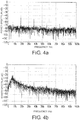
- Fig. 4a is a waveform chart illustrating an FFT processing waveform of a current sensed by the current sensor 31 when no arc is generated in either of the solar battery strings 11a and 11b.
- Fig. 4b is a waveform chart illustrating an FFT processing waveform of a current sensed by the current sensor 31 when an arc is generated in any of the solar battery strings 11a and 11b.
- the solar battery strings 11a and 11b generate power of a direct current.
- the power generated by the solar battery strings 11a and 11b is input to the PCS 13 via the string optimizer 22.
- a direct current output from the solar battery strings 11a and 11b is blocked by the capacitors 19 and 20 and does not flow in the bypass current routes 23 and 24.
- direct current power input via the string optimizer 22 is converted into alternating current power and is output.
- a current sensed by the current sensor 31 contains no alternating current of an arc.
- Fig. 4a illustrates the waveform of this current subjected to FFT processing by the FFT processing part 51.
- the waveform of an alternating current in the preceding stage (solar battery strings 11 a and 11b side) of the string optimizer 22 turns into a waveform in the arc generative state as illustrated in Fig. 3a .
- an alternating current of an arc flows from the power line 17a to the power line 18a via the bypass current route 23, the power line 17b, the PCS 13, the power line 18b, the bypass current route 24, the power line 18c, the power line 17c, and the bypass current route 72a.
- the waveform of an alternating current in the succeeding stage (PCS 13 side) of the string optimizer 22 turns into a waveform in the arc generative state as illustrated in Fig. 3b .
- an alternating current of an arc is sensed by the current sensor 31 provided in the power line 18b.
- a current sensed by the current sensor 31 contains an alternating current of an arc.
- Fig. 4b illustrates the waveform of this current subjected to FFT processing by the FFT processing part 51. Accordingly, the arc detection processing part 32 can detect generation of an arc in the solar battery strings 11a and 11b based on a high frequency component of a signal input from the current sensor 31.
- the arc detection apparatus 61 includes the bypass current routes 23, 24, and 72a with respect to the string optimizer 22 in the solar battery strings 11a and 11b in which the string optimizer 22 is provided.
- the capacitors 19, 20, and 71 a are respectively provided in the bypass current routes 23, 24, and 72a, and the current sensor 31 is provided in the power line 18b between the string optimizer 22 and the PCS 13. Therefore, even when the string optimizer 22 is present in the photovoltaic power generation system 1, the current sensor 31 can sense an alternating current of an arc generated in the solar battery strings 11a and 11b.
- the internal impedance of the string optimizer 22 and the internal impedance of the PCS 13 on the input side are illustrated in an equivalent circuit.
- the string optimizer 22 has an impedance Z in1 between the power lines 17a and 18a on the input side, an impedance Z in2 between the power lines 17c and 18c on the input side, an impedance Z out between the power lines 17b and 18b on the output side, an impedance Z 1 between the power lines 17a and 17b on the positive side, an impedance Z 2 between the power lines 18a and 18b on the negative side, and an impedance Z 3 between the power lines 18a and 17c adjacent to each other.
- the PCS 13 has an impedance Z PCSin between the power lines 17b and 18b on the input side. Other impedances in the PCS 13 are not illustrated. Moreover, the impedances of the capacitors 19, 20, and 71a are Z pass1 , Z pass2 , and Z pass3 respectively.
- the current sensor 31 In order for the current sensor 31 to detect the alternating current of an arc generated in the solar battery string 11 a, it is desirable that the amount of an alternating current flowing from the power line 17a to the power line 18a via the impedances Z pas1 and Z 1 , via the impedances Z out and Z PCSin , via the impedances Z pass2 and Z 2 , via the solar battery string 11b, and via the impedances Z pass3 and Z 3 be greater than the amount of an alternating current flowing from the power line 17a to the power line 18a via the impedance Z in1 .
- the current sensor 31 in order for the current sensor 31 to detect the alternating current of an arc generated in the solar battery string 11b, it is desirable that the amount of an alternating current flowing from the power line 17c to the power line 18c via the impedances Z pass3 and Z 3 , via the solar battery string 11a, via the impedances Z pass1 and Z 1 , via the impedance Z out and Z PCSin , and via the impedances Z pass2 and Z 2 be greater than the amount of an alternating current flowing from the power line 17c to the power line 18c via the impedance Z in2 .
- the current sensor 31 in order for the current sensor 31 to detect the alternating current of an arc, it is desirable that the amount of an alternating current flowing from the power line 17b to the power line 18b via the impedance Z PCSin be greater than the amount of an alternating current flowing in the impedance Z out . That is, it is desirable that the following Expression (2) be satisfied.
- the impedances Z in1 , Z in2 , Z out , Z 1 , Z 2 , and Z 3 in the string optimizer 22, and the impedance Z PCSin in the PCS 13 can be measured using an LCR meter, and the impedances Z pass1 , Z pass2 , and Z pass3 of the capacitors 19, 20, and 71 a can be easily determined using the measurement result and the Conditional Expression (1).
- a capacitor may be provided between the power line 17b and the power line 18b on the PCS 13 side of the current sensor 31 such that the Expression (2) is satisfied using the measurement result.
- the impedance Z pass2 may have any value. Therefore, when the impedance Z 2 is extremely smaller than the impedances Z in1 and Z in2 , the capacitor 20 having the impedance Z pass2 can be omitted.
- the solar battery strings 11a and 11b are connected in series or parallel, or both the series connection and the parallel connection can be realized.
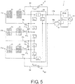
- Fig. 5 is a schematic circuit diagram illustrating a configuration of the photovoltaic power generation system including an arc detection apparatus according to another embodiment of the present invention.
- the photovoltaic power generation system 1 of the present embodiment is different from the photovoltaic power generation system 1 illustrated in Figs. 1 to 4 in that a new solar battery string 11c is connected to the string optimizer 22 through a power line 17d on the P-side and a power line 18d on the N-side serving as a pair of power circuits, and a bypass current route 72b and a capacitor 71b are added to the arc detection apparatus 61.
- Other configurations are similar.
- bypass current route 72b a first end portion (one end portion) is connected to the power line 18c between the string optimizer 22 and the solar battery string 11b, and a second end portion (the other end portion) is connected to the power line 17d (one of the pair of second power lines) between the string optimizer 22 and the solar battery string 11c, such that the bypass current route 72b bypasses the string optimizer 22.
- the capacitor 71b (inter-power source capacitor) is provided in the bypass current route 72b. That is, in the capacitor 71b, a first electrode is connected to the power line 18c, and a second electrode is connected to the power line 17d, thereby forming the bypass current route 72b.
- an impedance Z in3 between the power lines 17d and 18d on the input side, and an impedance Z 4 between the power lines 18c and 17d adjacent to each other are added to the string optimizer 22.
- the impedance of the capacitor 71b is Z pass4 .
- the current sensor 31 in order for the current sensor 31 to detect the alternating current of an arc generated in the solar battery string 11a, it is desirable that the amount of an alternating current flowing from the power line 17a to the power line 18a via the impedances Z pass1 and Z 1 , via the impedances Z out and Z PCSin , via the impedances Z pass2 and Z 2 , via the solar battery string 11c, via the impedances Z pass4 and Z 4 , via the solar battery string 11b, and via the impedances Zp ass3 and Z 3 be greater than the amount of an alternating current flowing from the power line 17a to the power line 18a via the impedance Z in1 .
- the current sensor 31 in order for the current sensor 31 to detect the alternating current of an arc generated in the solar battery string 11b, it is desirable that the amount of an alternating current flowing from the power line 17c to the power line 18c via the impedances Z pass3 and Z 3 , via the solar battery string 11a, via the impedances Z pass1 and Z 1 , via the impedances Z out and Z PCSin , via the impedances Z pass2 and Z 2 , via the solar battery string 11c, and via the impedances Z pass4 and Z 4 be greater than the amount of an alternating current flowing from the power line 17c to the power line 18c via the impedance Z in2 .
- the current sensor 31 in order for the current sensor 31 to detect the alternating current of an arc generated in the solar battery string 11c, it is desirable that the amount of an alternating current flowing from the power line 17d to the power line 18d via the impedances Z pass4 and Z 4 , via the solar battery string 11b, via the impedances Z pass3 and Z 3 , via the solar battery string 11a, via the impedances Z pass1 and Z 1 , via the impedances Z out and Z PCSin , and via the impedances Z pass2 and Z 2 be greater than the amount of an alternating current flowing from the power line 17d to the power line 18d via the impedance Z in3 .
- the number of solar battery strings connected to the string optimizer 22 via a pair of power lines may be two as illustrated in Fig. 1 , may be three as illustrated in Fig. 5 , or may be four or more.
- the impedances Z in1 , Z in2 , Z in3 , Z out , Z 1 , Z 2 , Z 3 , and Z 4 between terminals in the string optimizer 22, and the impedance Z PCSin in the PCS 13 can be measured using an LCR meter, and the impedances Z pass1 , Z pass2 , Z pass3 , and Z pass4 of the capacitors 19, 20, 71a, and 71b can be easily determined using the measurement result and the Conditional Expression (3).
- Fig. 6 is a schematic circuit diagram illustrating a configuration of the photovoltaic power generation system including an arc detection apparatus according to further another embodiment of the present invention.
- the photovoltaic power generation system 1 illustrated in Fig. 6 is different from the photovoltaic power generation system 1 illustrated in Figs. 1 to 4 in that two string parts 81 each including the solar battery strings 11a and 11b and the string optimizer 22 illustrated in Fig. 1 are provided, and a connection box 12 is provided. Other configurations are similar.
- the two string parts 81 and 81 are connected to the connection box 12, and the connection box 12 is connected to the PCS 13. In the connection box 12, the two string parts 81 and 81 are connected in parallel.
- the photovoltaic power generation system 1 may include a plurality of string optimizers 22.
- the bypass current routes 23, 24, and 72a bypassing the string optimizer 22 are provided for each of the string optimizers 22, and the capacitors 19, 20, and 71a are respectively provided in the bypass current routes 23, 24, and 72a.
- the current sensor 31 can sense an alternating current of an arc generated in any of the four solar battery strings 11a, 11a, 11b, and 11b.
- the arc detection apparatus 61 can detect generation of an arc in any of the four solar battery strings 11a, 11a, 11b, and 11b.
- Fig. 7 is a schematic circuit diagram illustrating a configuration of the photovoltaic power generation system including an arc detection apparatus according to an alternative embodiment of the present invention.
- the photovoltaic power generation system 1 of the present embodiment is different from the photovoltaic power generation system 1 illustrated in Figs. 1 to 4 in that a coil 25 is newly provided in each of the power lines 17a, 18a, 17c, and 18c on the input side of the string optimizer 22.
- Other configurations are similar.
- a first end portion (connection portion) is connected to the power line 17a between the coil 25 and the solar battery string 11a, and a second end portion is connected to the power line 17b between the string optimizer 22 and the current sensor 31, such that bypass current route 23 bypasses the coil 25 and the string optimizer 22.
- a first end portion is connected to the power line 18c between the coil 25 and the solar battery string 11b, and a second end portion is connected to the power line 18b between the string optimizer 22 and the PCS 13, such that the bypass current route 24 bypasses the coil 25 and the string optimizer 22.
- a first end portion (connection portion) is connected to the power line 18a between the coil 25 and the solar battery string 11 a, and a second end portion (connection portion) is connected to the power line 17c between the coil 25 and the solar battery string 11b, such that the bypass current route 72a bypasses the coils 25 and 25, and the string optimizer 22.
- the amount of an alternating current flowing from the power line 17a to the power line 18a via the coil 25, the impedance Z in1 , and the coil 25 is reduced.
- the amount of an alternating current flowing from the power line 17c to the power line 18c via the coil 25, the impedance Z in2 , and the coil 25 is reduced.
- the amount of an alternating current flowing from the power line 17c to the power line 18a via the coil 25, the impedance Z 3 , and the coil 25 is reduced.
- the coils 25 may be mounted inside an input portion of the string optimizer 22.
- the coil 25 provided in the power line 18c may be omitted.
- bypass current routes 23, 24, 72a, and 72b, and the capacitors 19, 20, 71a, and 71b are provided outside the string optimizer 22.
- the bypass current routes and the capacitors may be provided inside the string optimizer 22.
- the present invention is applied to a photovoltaic power generation system.
- the present invention is not limited thereto and can be applied to an arbitrary power supply system including a direct current power source.
- direct current power sources include a fuel cell apparatus which can acquire electric energy (direct current power) by utilizing hydrogen fuel for electrochemical reaction between hydrogen fuel and oxygen in the air, a storage battery which stores electric energy, and an electric condenser such as a capacitor.
Landscapes
- Engineering & Computer Science (AREA)
- Power Engineering (AREA)
- Physics & Mathematics (AREA)
- General Physics & Mathematics (AREA)
- Photovoltaic Devices (AREA)
- Testing Of Short-Circuits, Discontinuities, Leakage, Or Incorrect Line Connections (AREA)
- Supply And Distribution Of Alternating Current (AREA)
- Direct Current Feeding And Distribution (AREA)
Abstract
Description
- The present invention relates to an arc detection apparatus applied to a direct current power supply system.
- A photovoltaic power generation system includes a solar battery array. The solar battery array is configured to have a plurality of solar battery strings connected in parallel. Each of the solar battery strings is configured to have a plurality of solar battery modules connected in series. As an example, direct current power generated in each of the solar battery strings is converted into suitable direct current power and/or suitable alternating current power by a power conditioning system (PCS).
- In such a photovoltaic power generation system, sometimes an arc is generated due to a malfunction of a circuit or the like inside the system. When an arc is generated, the temperature of the arced part becomes high, and there is a risk of fire or the like. Therefore, the photovoltaic power generation system includes an arc detection apparatus which detects generation of an arc by causing a current sensor to sense an alternating current of an arc.
-
Patent Document 1 discloses a configuration in which power generated in a solar battery (photovoltaic generator) is supplied to an inverter via a DC power line. A current sensor is provided in the DC power line, and the presence or absence of generation of an arc is detected based on an alternating current sensed by the current sensor. -
- [Patent Document 1] PCT Japanese Translation Patent Publication No.
2014-509396 - [Patent Document 2] PCT Japanese Translation Patent Publication No.
2010-521720 - [Patent Document 3] PCT Japanese Translation Patent Publication No.
2012-510158 - Recently, in photovoltaic power generation systems, in order to more efficiently convert solar energy into power, an optimizer performing optimization of power, which has been performed using a PCS, in a solar battery string unit or a solar battery module unit is being utilized. Patent Documents 2 and 3 disclose specific configurations of such optimizers.
- However, when an arc is generated in a photovoltaic power generation system provided with such an optimizer, it is difficult for a current sensor to detect an alternating current of an arc. This is because the optimizer includes a DC-DC converting circuit. The DC-DC converting circuit converts a direct current voltage through a conversion method such as a chopper type, a fly-back type, and a forward type. However, all the conversion methods include a coil (inductor) in a circuit. Therefore, an alternating current component of an arc is reduced. In addition, since a capacitor is inserted into the circuit for voltage stabilization, a high frequency component of the alternating current of the arc flows due to the capacitor. As a result, no alternating current of an arc flows in the current sensor.
- Therefore, an object of an aspect of the present invention is to provide an arc detection apparatus which can detect an electric arc generated in a direct current power supply system such as a photovoltaic power generation system even if an optimizer is present.
- In order to solve the problems, according to an aspect of the present invention, there is provided an arc detection apparatus applied to a direct current power supply system including a plurality of direct current power sources for power generation or charging/discharging, an optimizer that optimizes output of the plurality of direct current power sources, a loading device that consumes or converts output power of the optimizer, a plurality of pairs of first power lines that connect the plurality of direct current power sources and the optimizer, and a pair of second power lines that connect the optimizer and the loading device. Each of the plurality of pairs has an inter-power source capacitor of which one end portion is connected to one of a certain pair of first power lines and of which the other end portion is connected to one of a different pair of first power lines. The arc detection apparatus includes a first capacitor of which one end portion is connected to one of the two first power lines having no inter-power source capacitor connected thereto and of which the other end portion is connected to one of the pair of second power lines, a current measuring part which measures a current in the second power lines, and an arc determining part which determines the presence or absence of an arc based on a high frequency component of an alternating current measured by the current measuring part.
- According to the configuration, the plurality of direct current power sources are connected to the optimizer via the plurality of pairs of first power lines respectively, and the optimizer is connected to the loading device via the second power lines. The first capacitor forms a first bypass current route bypassing the optimizer, and the inter-power source capacitor forms an inter-power source bypass current route bypassing the optimizer. The current measuring part measures a current in the second power lines.
- Therefore, even when the optimizer is present, the current measuring part in the second power lines can measure the alternating current of an arc generated in the plurality of direct current power sources. Accordingly, even when the optimizer is present in the direct current power supply system, the arc detection apparatus can detect an arc generated in the direct current power supply system.
- The first capacitor and the inter-power source capacitor may be provided outside the optimizer and may be provided inside the optimizer.
- In the arc detection apparatus according to the aspect, it is preferable that an impedance between the first capacitor and the inter-power source capacitor satisfy a condition that a joint impedance constituted of the impedance between the first capacitor and the inter-power source capacitor, an impedance of the optimizer between the two first power lines having no inter-power source capacitor connected thereto and the pair of second power lines, an impedance of the optimizer between the pair of second power lines, an impedance of the loading device, and an impedance of the optimizer between the first power lines each of which is provided with the inter-power source capacitor is smaller than any of the impedances of the optimizer between the pairs of first power lines. In this case, the amount of an alternating current flowing in the first capacitor and the inter-power source capacitor is greater than the amount of an alternating current flowing in the optimizer. Therefore, it is possible to reliably detect an arc generated in the direct current power supply system.
- The arc detection apparatus according to the aspect may further include a plurality of coils each of which is provided between a connection portion of the first capacitor in the first power lines and the inter-power source capacitor, and an input portion of the optimizer. In this case, the alternating current flowing in the first bypass current route and the inter-power source bypass current route increases, and the alternating current flowing in the current measuring part increases. As a result, it is possible to accurately detect an arc generated in the direct current power supply system. The coils may be provided inside the optimizer or may be provided outside the optimizer.
- Incidentally, depending on the optimizer, there are cases where the impedance of the optimizer between the other one of the two first power lines having no inter-power source capacitor connected thereto and the other one of the second power lines becomes significant.
- Therefore, the arc detection apparatus according to the aspect may further include a second capacitor of which one end portion is connected to the other one of the two first power lines and of which the other end portion is connected to the other one of the pair of second power lines. In this case, the second capacitor forms a second bypass current route bypassing the optimizer. Therefore, even if the impedance of the optimizer between the other one of the two first power lines and the other one of the second power lines is significant, the current measuring part in the second power lines can measure the alternating current of an arc generated in the plurality of direct current power sources. Accordingly, even when the optimizer is present in the direct current power supply system, the arc detection apparatus can detect an arc generated in the direct current power supply system.
- In the arc detection apparatus according to the aspect, it is preferable that an impedance among the first capacitor, the second capacitor, and the inter-power source capacitor satisfy a condition that a joint impedance constituted of the impedance among the first capacitor, the second capacitor, and the inter-power source capacitor, the impedance of the optimizer between the two first power lines having no inter-power source capacitor connected thereto and the pair of second power lines, the impedance of the optimizer between the pair of second power lines, the impedance of the loading device, and the impedance of the optimizer between the first power lines each of which is provided with the inter-power source capacitor is smaller than any of the impedances of the optimizer between the pairs of first power lines. In this case, the amount of an alternating current flowing in the first capacitor, the second capacitor, and the inter-power source capacitor is greater than the amount of an alternating current flowing in the optimizer. Therefore, it is possible to reliably detect an arc generated in the direct current power supply system.
- The arc detection apparatus according to the aspect may further include a coil between a connection portion of the second capacitor in the first power lines and the input portion of the optimizer. In this case, the alternating current flowing in the second bypass current route increases, and the alternating current flowing in the current measuring part increases. As a result, it is possible to accurately detect an arc generated in the direct current power supply system. The coil may be provided inside the optimizer or may be provided outside the optimizer.
- According to the aspect of the present invention, the first capacitor forms the first bypass current route bypassing the optimizer, and the inter-power source capacitor forms the inter-power source bypass current route bypassing the optimizer. Therefore, even when the optimizer is present in the direct current power supply system, the current measuring part in the second power lines can measure the alternating current of an arc generated in the plurality of direct current power sources. Accordingly, the arc detection apparatus can detect an arc generated in the direct current power supply system.
-
-
Fig. 1 is a schematic circuit diagram illustrating a configuration of a photovoltaic power generation system including an arc detection apparatus according to an embodiment of the present invention. -
Fig. 2 is a block diagram illustrating a configuration of an arc detection processing part of the arc detection apparatus included in the photovoltaic power generation system. -
Fig. 3a is a graph illustrating a waveform of an alternating current in a non-arc generative state and an arc generative state in a preceding stage of a string optimizer in the photovoltaic power generation system. -
Fig. 3b is a graph illustrating a waveform of an alternating current in a non-arc generative state and an arc generative state in a succeeding stage of the string optimizer. -
Fig. 4a is a waveform chart illustrating an FFT processing waveform of a current sensed by a current sensor in the arc detection apparatus when no arc is generated in the photovoltaic power generation system. -
Fig. 4b is a waveform chart illustrating an FFT processing waveform of a current sensed by the current sensor when an arc is generated in the photovoltaic power generation system. -
Fig. 5 is a schematic circuit diagram illustrating a configuration of the photovoltaic power generation system including an arc detection apparatus according to another embodiment of the present invention. -
Fig. 6 is a schematic circuit diagram illustrating a configuration of the photovoltaic power generation system including an arc detection apparatus according to further another embodiment of the present invention. -
Fig. 7 is a schematic circuit diagram illustrating a configuration of the photovoltaic power generation system including an arc detection apparatus according to an alternative embodiment of the present invention. - Hereinafter, embodiments of the present invention will be described in detail. For convenience of description, the same reference signs will be applied to members having the same functions illustrated in each of the embodiments, and the description thereof will be suitably omitted.
-
Fig. 1 is a schematic circuit diagram illustrating a configuration of a photovoltaic power generation system including an arc detection apparatus according to an embodiment of the present invention.Fig. 2 is a block diagram illustrating a configuration of an arc detection processing part of the arc detection apparatus included in the photovoltaic power generation system illustrated inFig. 1 . - As illustrated in
Fig. 1 , a photovoltaic power generation system 1 (direct current power supply system) includessolar battery strings - In each of the
solar battery strings solar battery modules 21 connected in series are formed. Each of thesolar battery modules 21 includes a plurality of solar battery cells (not illustrated) formed in a panel shape connected in series. - The
solar battery string 11a is connected to thestring optimizer 22 through apower line 17a on a P-side and apower line 18a on an N-side serving as a pair of power circuits (pair of first power lines). In addition, thesolar battery string 11b is connected to thestring optimizer 22 through apower line 17c on the P-side and thepower line 18c on the N-side serving as another pair of power circuits (pair of first power lines). - The
string optimizer 22 is connected to thePCS 13 through apower line 17b on the P-side and apower line 18b on the N-side serving as another pair of power circuits (pair of second power lines). Thestring optimizer 22 optimizes power from thesolar battery strings power lines solar battery strings PCS 13. - In the
PCS 13, direct current power input from thesolar battery strings string optimizer 22 is converted into alternating current power and the converted alternating current power is output to a power system 14 (loading device). In place of thePCS 13, a loading device consuming the direct current power may be provided. - The photovoltaic
power generation system 1 includes anarc detection apparatus 61. Thearc detection apparatus 61 includes bypasscurrent routes capacitors Fig. 2 ). - In the bypass
current route 23, a first end portion (one end portion) is connected to thepower line 17a (one of the first power lines having no inter-power source capacitor connected thereto) between thestring optimizer 22 and thesolar battery string 11a, and a second end portion (the other end portion) is connected to thepower line 17b (one of the pair of second power lines) between thestring optimizer 22 and thePCS 13, such that the bypasscurrent route 23 bypasses thestring optimizer 22. - The capacitor 19 (first capacitor) is provided in the bypass
current route 23. That is, in thecapacitor 19, a first electrode is connected to thepower line 17a, and a second electrode is connected to thepower line 17b, thereby forming the bypasscurrent route 23. The static capacitance (impedance) of thecapacitor 19 will be described below. - In the bypass
current route 24, a first end portion (one end portion) is connected to thepower line 18c (the other one of the first power lines having no inter-power source capacitor connected thereto) between thestring optimizer 22 and thesolar battery string 11b, and a second end portion (the other end portion) is connected to thepower line 18b (the other one of the pair of second power lines) between thestring optimizer 22 and thePCS 13, such that the bypasscurrent route 24 bypasses thestring optimizer 22. - The capacitor 20 (second capacitor) is provided in the bypass
current route 24. That is, in thecapacitor 20, a first electrode is connected to thepower line 18c, and a second electrode is connected to thepower line 18b, thereby forming the bypasscurrent route 24. The static capacitance (impedance) of thecapacitor 20 will be described below. - In the bypass
current route 72a, a first end portion (one end portion) is connected to thepower line 18a (one of a certain pair of first power lines) between thestring optimizer 22 and thesolar battery string 11 a, and a second end portion (the other end portion) is connected to thepower line 17c (one of a different pair of first power lines) between thestring optimizer 22 and thesolar battery string 11b, such that the bypasscurrent route 72a bypasses thestring optimizer 22. - The
capacitor 71a (inter-power source capacitor) is provided in the bypasscurrent route 72a. That is, in thecapacitor 71 a, the first electrode is connected to thepower line 18a, and the second electrode is connected to thepower line 17c, thereby forming the bypasscurrent route 72a. The static capacitance (impedance) of thecapacitor 71a will be described below. - The
current sensor 31 senses an alternating current flowing from thepower line 18c to thepower line 18b via the bypasscurrent route 24 based on an arc generated in thesolar battery string 11a or thesolar battery string 11b. Thecurrent sensor 31 may be provided in thepower line 17b. In this case, thecurrent sensor 31 senses an alternating current flowing from thepower line 17a to thepower line 17b via the bypasscurrent route 23 based on the arc. - The arc
detection processing part 32 has a configuration known in the related art. For example, as illustrated inFig. 2 , the arcdetection processing part 32 includes anamplifier 41, afilter 42, an A/D converter 43, and a central processing unit (CPU) 44. - The
amplifier 41 amplifies a current sensed by thecurrent sensor 31. Thefilter 42 is a band-pass filter (BPF) allowing a current only within a predetermined frequency range among currents output from theamplifier 41 to pass through. Accordingly, among the currents output from theamplifier 41, it is possible to eliminate a current having a frequency component containing plenty of switching noise of a converter (DC-DC converter) included in thePCS 13. The A/D converter 43 converts an analog signal of a current which has passed through thefilter 42 into a digital signal and inputs the digital signal to theCPU 44. - The
CPU 44 includes anFFT processing part 51 and an arc presence/absence determining part 52. TheFFT processing part 51 performs FFT (Fast Fourier Transform) with respect to a digital signal of a current input from the A/D converter 43 and generates a power spectrum of the current. The arc presence/absence determining part 52 determines the presence or absence of generation of an arc based on the power spectrum of the current generated by theFFT processing part 51. - Operations of the photovoltaic
power generation system 1 and thearc detection apparatus 61 in the configuration described above will be described below. -
Fig. 3a is a graph illustrating a waveform of an alternating current in a non-arc generative state and an arc generative state in a preceding stage (solar battery strings 11 a and 11b side) of thestring optimizer 22.Fig. 3b is a graph illustrating a waveform of an alternating current in a non-arc generative state and an arc generative state in a succeeding stage (PCS 13 side) of thestring optimizer 22. -
Fig. 4a is a waveform chart illustrating an FFT processing waveform of a current sensed by thecurrent sensor 31 when no arc is generated in either of thesolar battery strings Fig. 4b is a waveform chart illustrating an FFT processing waveform of a current sensed by thecurrent sensor 31 when an arc is generated in any of thesolar battery strings - The
solar battery strings solar battery strings PCS 13 via thestring optimizer 22. In this case, a direct current output from thesolar battery strings capacitors current routes PCS 13, direct current power input via thestring optimizer 22 is converted into alternating current power and is output. - Here, when no arc is generated in either of the
solar battery strings solar battery strings string optimizer 22 turns into a waveform in the non-arc generative state as illustrated inFig. 3a . Therefore, a current sensed by thecurrent sensor 31 contains no alternating current of an arc.Fig. 4a illustrates the waveform of this current subjected to FFT processing by theFFT processing part 51. - Meanwhile, when an arc is generated in any of the
solar battery strings string optimizer 22 turns into a waveform in the arc generative state as illustrated inFig. 3a . In this case, although no alternating current of an arc flows in thestring optimizer 22, an alternating current of an arc flows from thepower line 17a to thepower line 18a via the bypasscurrent route 23, thepower line 17b, thePCS 13, thepower line 18b, the bypasscurrent route 24, thepower line 18c, thepower line 17c, and the bypasscurrent route 72a. Therefore, the waveform of an alternating current in the succeeding stage (PCS 13 side) of thestring optimizer 22 turns into a waveform in the arc generative state as illustrated inFig. 3b . In addition, an alternating current of an arc is sensed by thecurrent sensor 31 provided in thepower line 18b. - Therefore, a current sensed by the
current sensor 31 contains an alternating current of an arc.Fig. 4b illustrates the waveform of this current subjected to FFT processing by theFFT processing part 51. Accordingly, the arcdetection processing part 32 can detect generation of an arc in thesolar battery strings current sensor 31. - As described above, the
arc detection apparatus 61 includes the bypasscurrent routes string optimizer 22 in thesolar battery strings string optimizer 22 is provided. In addition, thecapacitors current routes current sensor 31 is provided in thepower line 18b between thestring optimizer 22 and thePCS 13. Therefore, even when thestring optimizer 22 is present in the photovoltaicpower generation system 1, thecurrent sensor 31 can sense an alternating current of an arc generated in thesolar battery strings - In
Fig. 1 , the internal impedance of thestring optimizer 22 and the internal impedance of thePCS 13 on the input side are illustrated in an equivalent circuit. As illustrated inFig. 1 , thestring optimizer 22 has an impedance Zin1 between thepower lines power lines power lines power lines power lines power lines PCS 13 has an impedance ZPCSin between thepower lines PCS 13 are not illustrated. Moreover, the impedances of thecapacitors - In order for the
current sensor 31 to detect the alternating current of an arc generated in thesolar battery string 11 a, it is desirable that the amount of an alternating current flowing from thepower line 17a to thepower line 18a via the impedances Zpas1 and Z1, via the impedances Zout and ZPCSin, via the impedances Zpass2 and Z2, via thesolar battery string 11b, and via the impedances Zpass3 and Z3 be greater than the amount of an alternating current flowing from thepower line 17a to thepower line 18a via the impedance Zin1. - Similarly, in order for the
current sensor 31 to detect the alternating current of an arc generated in thesolar battery string 11b, it is desirable that the amount of an alternating current flowing from thepower line 17c to thepower line 18c via the impedances Zpass3 and Z3, via thesolar battery string 11a, via the impedances Zpass1 and Z1, via the impedance Zout and ZPCSin, and via the impedances Zpass2 and Z2 be greater than the amount of an alternating current flowing from thepower line 17c to thepower line 18c via the impedance Zin2. - That is, it is desirable that the following Conditional Expression (1) be satisfied.

- In addition, in order for the
current sensor 31 to detect the alternating current of an arc, it is desirable that the amount of an alternating current flowing from thepower line 17b to thepower line 18b via the impedance ZPCSin be greater than the amount of an alternating current flowing in the impedance Zout. That is, it is desirable that the following Expression (2) be satisfied.
- Therefore, for example, the impedances Zin1, Zin2, Zout, Z1, Z2, and Z3 in the
string optimizer 22, and the impedance ZPCSin in thePCS 13 can be measured using an LCR meter, and the impedances Zpass1, Zpass2, and Zpass3 of thecapacitors power line 17b and thepower line 18b on thePCS 13 side of thecurrent sensor 31 such that the Expression (2) is satisfied using the measurement result. - Moreover, with reference to the Conditional Expression (1), when Z2 << Zin1 and Zin2, it is possible to understand that the impedance Zpass2 may have any value. Therefore, when the impedance Z2 is extremely smaller than the impedances Zin1 and Zin2, the
capacitor 20 having the impedance Zpass2 can be omitted. - Incidentally, depending on the
string optimizer 22, thesolar battery strings arc detection apparatus 61 of the present embodiment. -
Fig. 5 is a schematic circuit diagram illustrating a configuration of the photovoltaic power generation system including an arc detection apparatus according to another embodiment of the present invention. As illustrated inFig. 5 , the photovoltaicpower generation system 1 of the present embodiment is different from the photovoltaicpower generation system 1 illustrated inFigs. 1 to 4 in that a new solar battery string 11c is connected to thestring optimizer 22 through apower line 17d on the P-side and apower line 18d on the N-side serving as a pair of power circuits, and a bypasscurrent route 72b and acapacitor 71b are added to thearc detection apparatus 61. Other configurations are similar. - In the bypass
current route 72b, a first end portion (one end portion) is connected to thepower line 18c between thestring optimizer 22 and thesolar battery string 11b, and a second end portion (the other end portion) is connected to thepower line 17d (one of the pair of second power lines) between thestring optimizer 22 and the solar battery string 11c, such that the bypasscurrent route 72b bypasses thestring optimizer 22. - The
capacitor 71b (inter-power source capacitor) is provided in the bypasscurrent route 72b. That is, in thecapacitor 71b, a first electrode is connected to thepower line 18c, and a second electrode is connected to thepower line 17d, thereby forming the bypasscurrent route 72b. - In the case of the configuration described above, as illustrated in
Fig. 5 , an impedance Zin3 between thepower lines power lines string optimizer 22. The impedance of thecapacitor 71b is Zpass4. - In the configuration described above, in order for the
current sensor 31 to detect the alternating current of an arc generated in thesolar battery string 11a, it is desirable that the amount of an alternating current flowing from thepower line 17a to thepower line 18a via the impedances Zpass1 and Z1, via the impedances Zout and ZPCSin, via the impedances Zpass2 and Z2, via the solar battery string 11c, via the impedances Zpass4 and Z4, via thesolar battery string 11b, and via the impedances Zpass3 and Z3 be greater than the amount of an alternating current flowing from thepower line 17a to thepower line 18a via the impedance Zin1. - Similarly, in order for the
current sensor 31 to detect the alternating current of an arc generated in thesolar battery string 11b, it is desirable that the amount of an alternating current flowing from thepower line 17c to thepower line 18c via the impedances Zpass3 and Z3, via thesolar battery string 11a, via the impedances Zpass1 and Z1, via the impedances Zout and ZPCSin, via the impedances Zpass2 and Z2, via the solar battery string 11c, and via the impedances Zpass4 and Z4 be greater than the amount of an alternating current flowing from thepower line 17c to thepower line 18c via the impedance Zin2. - Similarly, in order for the
current sensor 31 to detect the alternating current of an arc generated in the solar battery string 11c, it is desirable that the amount of an alternating current flowing from thepower line 17d to thepower line 18d via the impedances Zpass4 and Z4, via thesolar battery string 11b, via the impedances Zpass3 and Z3, via thesolar battery string 11a, via the impedances Zpass1 and Z1, via the impedances Zout and ZPCSin, and via the impedances Zpass2 and Z2 be greater than the amount of an alternating current flowing from thepower line 17d to thepower line 18d via the impedance Zin3. - That is, it is desirable that the following Conditional Expression (3) be satisfied.

- Therefore, the number of solar battery strings connected to the
string optimizer 22 via a pair of power lines may be two as illustrated inFig. 1 , may be three as illustrated inFig. 5 , or may be four or more. - In addition, for example, the impedances Zin1, Zin2, Zin3, Zout, Z1, Z2, Z3, and Z4 between terminals in the
string optimizer 22, and the impedance ZPCSin in thePCS 13 can be measured using an LCR meter, and the impedances Zpass1, Zpass2, Zpass3, and Zpass4 of thecapacitors -
Fig. 6 is a schematic circuit diagram illustrating a configuration of the photovoltaic power generation system including an arc detection apparatus according to further another embodiment of the present invention. The photovoltaicpower generation system 1 illustrated inFig. 6 is different from the photovoltaicpower generation system 1 illustrated inFigs. 1 to 4 in that twostring parts 81 each including thesolar battery strings string optimizer 22 illustrated inFig. 1 are provided, and aconnection box 12 is provided. Other configurations are similar. - The two
string parts connection box 12, and theconnection box 12 is connected to thePCS 13. In theconnection box 12, the twostring parts - As in the configuration above, the photovoltaic
power generation system 1 may include a plurality ofstring optimizers 22. In this case, the bypasscurrent routes string optimizer 22 are provided for each of thestring optimizers 22, and thecapacitors current routes current sensor 31 can sense an alternating current of an arc generated in any of the foursolar battery strings arc detection apparatus 61 can detect generation of an arc in any of the foursolar battery strings -
Fig. 7 is a schematic circuit diagram illustrating a configuration of the photovoltaic power generation system including an arc detection apparatus according to an alternative embodiment of the present invention. As illustrated inFig. 7 , the photovoltaicpower generation system 1 of the present embodiment is different from the photovoltaicpower generation system 1 illustrated inFigs. 1 to 4 in that acoil 25 is newly provided in each of thepower lines string optimizer 22. Other configurations are similar. - In the present embodiment, in the bypass
current route 23, a first end portion (connection portion) is connected to thepower line 17a between thecoil 25 and thesolar battery string 11a, and a second end portion is connected to thepower line 17b between thestring optimizer 22 and thecurrent sensor 31, such that bypasscurrent route 23 bypasses thecoil 25 and thestring optimizer 22. Similarly, in the bypasscurrent route 24, a first end portion is connected to thepower line 18c between thecoil 25 and thesolar battery string 11b, and a second end portion is connected to thepower line 18b between thestring optimizer 22 and thePCS 13, such that the bypasscurrent route 24 bypasses thecoil 25 and thestring optimizer 22. - In addition, in the bypass
current route 72a, a first end portion (connection portion) is connected to thepower line 18a between thecoil 25 and thesolar battery string 11 a, and a second end portion (connection portion) is connected to thepower line 17c between thecoil 25 and thesolar battery string 11b, such that the bypasscurrent route 72a bypasses thecoils string optimizer 22. - When the four
coils 25 are added, the amount of an alternating current flowing from thepower line 17a to thepower line 18a via thecoil 25, the impedance Zin1, and thecoil 25 is reduced. In addition, the amount of an alternating current flowing from thepower line 17c to thepower line 18c via thecoil 25, the impedance Zin2, and thecoil 25 is reduced. In addition, the amount of an alternating current flowing from thepower line 17c to thepower line 18a via thecoil 25, the impedance Z3, and thecoil 25 is reduced. - Therefore, the amount of an alternating current flowing in the bypass
current routes current sensor 31 increases. As a result, it is possible to accurately detect generation of an arc. Thecoils 25 may be mounted inside an input portion of thestring optimizer 22. In addition, when thecapacitor 20 can be omitted as described above, thecoil 25 provided in thepower line 18c may be omitted. - In the embodiments, the bypass
current routes capacitors string optimizer 22. However, the bypass current routes and the capacitors may be provided inside thestring optimizer 22. - In addition, in the embodiments, the present invention is applied to a photovoltaic power generation system. However, the present invention is not limited thereto and can be applied to an arbitrary power supply system including a direct current power source. In addition to a photovoltaic power generation apparatus, examples of direct current power sources include a fuel cell apparatus which can acquire electric energy (direct current power) by utilizing hydrogen fuel for electrochemical reaction between hydrogen fuel and oxygen in the air, a storage battery which stores electric energy, and an electric condenser such as a capacitor.
-
- 1 photovoltaic power generation system
- 11a-11c solar battery strings
- 13 power conditioning system
- 14 power system
- 17a-17d, 18a-18d power line
- 19, 20, 71a, 71b capacitor
- 22 string optimizer
- 23, 24, 72a, 72b bypass current route
- 25 coil
- 31 current sensor
- 32 arc detection processing part
- 41 amplifier
- 42 filter
- 43 A/D converter
- 44 central processing unit
- 51 FFT processing part
- 52 arc presence/absence determining part
- 61 arc detection apparatus
- Zin1-Zin3, Zout, Z1-Z4, Zpass1-Zpass4, ZPCSin impedance
Claims (6)
- An arc detection apparatus (61) applied to a direct current power supply system (1) comprising:a plurality of direct current power sources (11a, 11b) for power generation or charging/discharging;an optimizer (22) that optimizes output of the plurality of direct current power sources(11a,11b);a loading device (13) that consumes or converts output power of the optimizer (22);a plurality of pairs of first power lines (17a, 17c, 18a, 18c) that connect the plurality of direct current power sources (11a, 11b) and the optimizer (22); anda pair of second power lines (17b, 18b) that connect the optimizer (22) and the loading device (13),wherein each of the plurality of pairs of first power lines (17a, 17c, 18a, 18c) has an inter-power source capacitor (71a) of which one end portion is connected to one of a certain pair of first power lines (17a, 17c, 18a, 18c) and of which the other end portion is connected to one of a different pair of first power lines (17a, 17c, 18a, 18c), andwherein the arc detection apparatus (61) comprises:a first capacitor (19) of which one end portion is connected to one of the two first power lines (17a, 17c, 18a, 18c) having no inter-power source capacitor (71a) connected thereto and of which the other end portion is connected to one of the pair of second power lines (17b, 18b);a current measuring part (31) which measures a current in the second power lines (17b, 18b), andan arc determining part (52) which determines the presence or absence of an arc based on a high frequency component of an alternating current measured by the current measuring part (31).
- The arc detection apparatus (61) according to claim 1,wherein an impedance between the first capacitor (19) and the inter-power source capacitor (71a) satisfies a condition that a joint impedance constituted of the impedance between the first capacitor (19) and the inter-power source capacitor (71a), an impedance of the optimizer (22) between the two first power lines (17a, 17c, 18a, 18c) having no inter-power source capacitor (71a) connected thereto and the pair of second power lines (17b, 18b), an impedance of the optimizer (22) between the pair of second power lines (17b, 18b), an impedance of the loading device (13), and an impedance of the optimizer (22) between the first power lines (17a, 17c, 18a, 18c) each of which is provided with the inter-power source capacitor (71a) is smaller than any of the impedances of the optimizer (22) between each of the plurality of pairs of first power lines (17a, 17c, 18a, 18c).
- The arc detection apparatus (61) according to claim 1 or 2, further comprising:a plurality of coils each of which is provided between a connection portion of the first capacitor (19) in the first power lines (17a, 17c, 18a, 18c) and the inter-power source capacitor (71a), and an input portion of the optimizer (22).
- The arc detection apparatus (61) according to any one of claims 1 to 3, further comprising:a second capacitor (20) of which one end portion is connected to the other one of the two first power lines (17a, 17c, 18a, 18c) having no inter-power source capacitor (71a) connected thereto and of which the other end portion is connected to the other one of the pair of second power lines (17b, 18b).
- The arc detection apparatus (61) according to claim 4,wherein an impedance among the first capacitor (19), the second capacitor (20), and the inter-power source capacitor (71 a) satisfies a condition that a joint impedance constituted of the impedance among the first capacitor (19), the second capacitor (20), and the inter-power source capacitor (71a), the impedance of the optimizer (22) between the two first power lines (17a, 17c, 18a, 18c) having no inter-power source capacitor (71 a) connected thereto and the pair of second power lines (17b, 18b), the impedance of the optimizer (22) between the pair of second power lines (17b, 18b), the impedance of the loading device (13), and the impedance of the optimizer (22) between the first power lines (17a, 17c, 18a, 18c) each of which is provided with the inter-power source capacitor (71a) is smaller than any of the impedances of the optimizer (22) between each of the plurality of pairs of first power lines (17a, 17c, 18a, 18c).
- The arc detection apparatus (61) according to claim 4 or 5, further comprising:a coil (25) between a connection portion of the second capacitor (20) in the first power lines (17a, 17c, 18a, 18c) and the input portion of the optimizer (22).
Applications Claiming Priority (1)
| Application Number | Priority Date | Filing Date | Title |
|---|---|---|---|
| JP2017018968A JP6658586B2 (en) | 2017-02-03 | 2017-02-03 | Arc detector |
Publications (1)
| Publication Number | Publication Date |
|---|---|
| EP3358691A1 true EP3358691A1 (en) | 2018-08-08 |
Family
ID=60421587
Family Applications (1)
| Application Number | Title | Priority Date | Filing Date |
|---|---|---|---|
| EP17202104.0A Withdrawn EP3358691A1 (en) | 2017-02-03 | 2017-11-16 | Arc detection apparatus |
Country Status (3)
| Country | Link |
|---|---|
| US (1) | US20180226919A1 (en) |
| EP (1) | EP3358691A1 (en) |
| JP (1) | JP6658586B2 (en) |
Families Citing this family (7)
| Publication number | Priority date | Publication date | Assignee | Title |
|---|---|---|---|---|
| KR102021927B1 (en) * | 2019-04-02 | 2019-09-17 | (주)신호엔지니어링 | Photovoltaic System Having Fire Prediction Function |
| KR102021913B1 (en) * | 2019-04-02 | 2019-09-17 | (주)신호엔지니어링 | Fire Prevention System Of Photovoltaic Apparatus |
| CN115151830B (en) * | 2020-03-11 | 2025-03-07 | 松下知识产权经营株式会社 | Arc detection devices, power conditioners, indoor wiring systems, circuit breakers, solar panels, solar panel accessory modules, and junction boxes |
| CN112305308B (en) * | 2020-10-21 | 2023-08-11 | 阳光电源股份有限公司 | DC arc detection method, device and string inverter |
| CN115021676B (en) * | 2022-06-01 | 2025-09-02 | 阳光电源股份有限公司 | Photovoltaic system DC arc fault detection method, device, equipment and medium |
| CN114696742B (en) * | 2022-06-01 | 2022-09-13 | 阳光电源股份有限公司 | Photovoltaic system direct current arc fault detection method, device, equipment and medium |
| CN115549037B (en) * | 2022-09-06 | 2026-06-05 | 国网青海省电力公司超高压公司 | A method and system for preventing maloperation of DC grounding relay protection |
Citations (6)
| Publication number | Priority date | Publication date | Assignee | Title |
|---|---|---|---|---|
| JP2010521720A (en) | 2006-12-06 | 2010-06-24 | ソーラーエッジ テクノロジーズ | Distributed power harvesting system using DC power supply |
| JP2012510158A (en) | 2008-11-26 | 2012-04-26 | タイゴ エナジー インコーポレイテッド | System and method for balancing solar panels in a multi-panel system |
| US20120318320A1 (en) * | 2011-06-17 | 2012-12-20 | Steven Andrew Robbins | System and Method for Arc Detection in Solar Power Arrays |
| US20140055900A1 (en) * | 2012-08-27 | 2014-02-27 | Charles John Luebke | Method and apparatus for enhancing arc fault signal for detection in photovoltaic system |
| JP2014509396A (en) | 2011-02-28 | 2014-04-17 | エスエムエー ソーラー テクノロジー アーゲー | Method and system for detecting arc faults in power circuits |
| KR101677925B1 (en) * | 2016-05-02 | 2016-11-29 | 주식회사 디투엔지니어링 | Photovoltaic gneration system with function of photovoltaic array individual monitoring |
Family Cites Families (6)
| Publication number | Priority date | Publication date | Assignee | Title |
|---|---|---|---|---|
| US8158877B2 (en) * | 2007-03-30 | 2012-04-17 | Sunpower Corporation | Localized power point optimizer for solar cell installations |
| US9043039B2 (en) * | 2011-02-24 | 2015-05-26 | Tigo Energy, Inc. | System and method for arc detection and intervention in solar energy systems |
| US9502885B2 (en) * | 2012-11-16 | 2016-11-22 | Sensata Technologies, Inc. | Home run arc detection at the photovoltaic string level using multiple current sensors |
| KR101452776B1 (en) * | 2013-07-10 | 2014-12-17 | 엘에스산전 주식회사 | Photovoltaic system |
| EP2996157B1 (en) * | 2014-09-09 | 2016-05-25 | SMA Solar Technology AG | Method for detecting of and detection device for electric arcing in a photovoltaic system |
| JP6037071B1 (en) * | 2016-03-07 | 2016-11-30 | オムロン株式会社 | Arc detector |
-
2017
- 2017-02-03 JP JP2017018968A patent/JP6658586B2/en not_active Expired - Fee Related
- 2017-11-16 EP EP17202104.0A patent/EP3358691A1/en not_active Withdrawn
- 2017-11-22 US US15/820,454 patent/US20180226919A1/en not_active Abandoned
Patent Citations (6)
| Publication number | Priority date | Publication date | Assignee | Title |
|---|---|---|---|---|
| JP2010521720A (en) | 2006-12-06 | 2010-06-24 | ソーラーエッジ テクノロジーズ | Distributed power harvesting system using DC power supply |
| JP2012510158A (en) | 2008-11-26 | 2012-04-26 | タイゴ エナジー インコーポレイテッド | System and method for balancing solar panels in a multi-panel system |
| JP2014509396A (en) | 2011-02-28 | 2014-04-17 | エスエムエー ソーラー テクノロジー アーゲー | Method and system for detecting arc faults in power circuits |
| US20120318320A1 (en) * | 2011-06-17 | 2012-12-20 | Steven Andrew Robbins | System and Method for Arc Detection in Solar Power Arrays |
| US20140055900A1 (en) * | 2012-08-27 | 2014-02-27 | Charles John Luebke | Method and apparatus for enhancing arc fault signal for detection in photovoltaic system |
| KR101677925B1 (en) * | 2016-05-02 | 2016-11-29 | 주식회사 디투엔지니어링 | Photovoltaic gneration system with function of photovoltaic array individual monitoring |
Also Published As
| Publication number | Publication date |
|---|---|
| JP6658586B2 (en) | 2020-03-04 |
| US20180226919A1 (en) | 2018-08-09 |
| JP2018124251A (en) | 2018-08-09 |
Similar Documents
| Publication | Publication Date | Title |
|---|---|---|
| US20180226919A1 (en) | Arc detection apparatus | |
| EP3355430B1 (en) | Arc detection apparatus | |
| US20220045544A1 (en) | Battery monitoring device | |
| JP4589888B2 (en) | Battery voltage measurement circuit and battery ECU | |
| EP3040728B1 (en) | Stacked battery impedance measurement device and measurement method | |
| EP3352315B1 (en) | Arc detection apparatus | |
| US20150142348A1 (en) | Power calculating method adapted to wireless power system | |
| EP3200341B1 (en) | Method and device for inspecting photovoltaic power generation system | |
| CN102818925A (en) | Isolated resistive current sensor | |
| US9176199B2 (en) | Method and system for detecting a defect on the DC power supply bus of a power converter | |
| EP4297212A1 (en) | Power supply apparatus, and method for measuring insulation resistance of input end of power supply apparatus | |
| KR20170138167A (en) | Device for measuring a loss in a reactive power compensation system | |
| JP6547659B2 (en) | Arc detector | |
| JP2018096761A (en) | Inspection support device and method for controlling the same, inspection system, and control program | |
| EP3428663B1 (en) | Inspection device, control method for same, and control program | |
| CN102621369A (en) | Inductance ESR (equivalent series resistance) based electric current detection circuit with potential floating function | |
| US12021203B2 (en) | Battery module monitoring board EMI reduction | |
| JP7418954B2 (en) | Power conditioner and energy storage system | |
| US20240317085A1 (en) | System and method for controlling electric power of vehicle battery | |
| JP4732292B2 (en) | Input impedance measuring apparatus and method | |
| CN110967572A (en) | On-vehicle pulse power source voltage current fault rapid detection device | |
| CN222189377U (en) | Hall sampling device and contain its energy storage dc-to-ac converter | |
| CN102207519A (en) | Current detecting method and circuit for power management integrated circuit | |
| JP2021196273A (en) | Voltage detection circuit | |
| US20240258910A1 (en) | Power converter and method for operating a power converter |
Legal Events
| Date | Code | Title | Description |
|---|---|---|---|
| PUAI | Public reference made under article 153(3) epc to a published international application that has entered the european phase |
Free format text: ORIGINAL CODE: 0009012 |
|
| STAA | Information on the status of an ep patent application or granted ep patent |
Free format text: STATUS: REQUEST FOR EXAMINATION WAS MADE |
|
| 17P | Request for examination filed |
Effective date: 20171116 |
|
| AK | Designated contracting states |
Kind code of ref document: A1 Designated state(s): AL AT BE BG CH CY CZ DE DK EE ES FI FR GB GR HR HU IE IS IT LI LT LU LV MC MK MT NL NO PL PT RO RS SE SI SK SM TR |
|
| AX | Request for extension of the european patent |
Extension state: BA ME |
|
| RBV | Designated contracting states (corrected) |
Designated state(s): AL AT BE BG CH CY CZ DE DK EE ES FI FR GB GR HR HU IE IS IT LI LT LU LV MC MK MT NL NO PL PT RO RS SE SI SK SM TR |
|
| STAA | Information on the status of an ep patent application or granted ep patent |
Free format text: STATUS: THE APPLICATION HAS BEEN WITHDRAWN |
|
| 18W | Application withdrawn |
Effective date: 20191205 |