EP3358595A1 - Multistage fuse - Google Patents
Multistage fuse Download PDFInfo
- Publication number
- EP3358595A1 EP3358595A1 EP17824546.0A EP17824546A EP3358595A1 EP 3358595 A1 EP3358595 A1 EP 3358595A1 EP 17824546 A EP17824546 A EP 17824546A EP 3358595 A1 EP3358595 A1 EP 3358595A1
- Authority
- EP
- European Patent Office
- Prior art keywords
- fuse
- bar
- contact
- melted
- multistage
- Prior art date
- Legal status (The legal status is an assumption and is not a legal conclusion. Google has not performed a legal analysis and makes no representation as to the accuracy of the status listed.)
- Granted
Links
Images


Classifications
-
- H—ELECTRICITY
- H01—ELECTRIC ELEMENTS
- H01H—ELECTRIC SWITCHES; RELAYS; SELECTORS; EMERGENCY PROTECTIVE DEVICES
- H01H85/00—Protective devices in which the current flows through a part of fusible material and this current is interrupted by displacement of the fusible material when this current becomes excessive
- H01H85/02—Details
- H01H85/20—Bases for supporting the fuse; Separate parts thereof
- H01H85/201—Bases for supporting the fuse; Separate parts thereof for connecting a fuse in a lead and adapted to be supported by the lead alone
-
- H—ELECTRICITY
- H01—ELECTRIC ELEMENTS
- H01H—ELECTRIC SWITCHES; RELAYS; SELECTORS; EMERGENCY PROTECTIVE DEVICES
- H01H85/00—Protective devices in which the current flows through a part of fusible material and this current is interrupted by displacement of the fusible material when this current becomes excessive
- H01H85/02—Details
- H01H85/04—Fuses, i.e. expendable parts of the protective device, e.g. cartridges
- H01H85/05—Component parts thereof
- H01H85/055—Fusible members
-
- H—ELECTRICITY
- H01—ELECTRIC ELEMENTS
- H01H—ELECTRIC SWITCHES; RELAYS; SELECTORS; EMERGENCY PROTECTIVE DEVICES
- H01H85/00—Protective devices in which the current flows through a part of fusible material and this current is interrupted by displacement of the fusible material when this current becomes excessive
- H01H85/02—Details
- H01H85/04—Fuses, i.e. expendable parts of the protective device, e.g. cartridges
- H01H85/05—Component parts thereof
- H01H85/055—Fusible members
- H01H85/08—Fusible members characterised by the shape or form of the fusible member
-
- H—ELECTRICITY
- H01—ELECTRIC ELEMENTS
- H01H—ELECTRIC SWITCHES; RELAYS; SELECTORS; EMERGENCY PROTECTIVE DEVICES
- H01H85/00—Protective devices in which the current flows through a part of fusible material and this current is interrupted by displacement of the fusible material when this current becomes excessive
- H01H85/02—Details
- H01H85/04—Fuses, i.e. expendable parts of the protective device, e.g. cartridges
- H01H85/05—Component parts thereof
- H01H85/143—Electrical contacts; Fastening fusible members to such contacts
-
- H—ELECTRICITY
- H01—ELECTRIC ELEMENTS
- H01H—ELECTRIC SWITCHES; RELAYS; SELECTORS; EMERGENCY PROTECTIVE DEVICES
- H01H85/00—Protective devices in which the current flows through a part of fusible material and this current is interrupted by displacement of the fusible material when this current becomes excessive
- H01H85/02—Details
- H01H85/20—Bases for supporting the fuse; Separate parts thereof
-
- H—ELECTRICITY
- H01—ELECTRIC ELEMENTS
- H01H—ELECTRIC SWITCHES; RELAYS; SELECTORS; EMERGENCY PROTECTIVE DEVICES
- H01H85/00—Protective devices in which the current flows through a part of fusible material and this current is interrupted by displacement of the fusible material when this current becomes excessive
- H01H85/02—Details
- H01H85/26—Magazine arrangements
- H01H85/28—Magazine arrangements effecting automatic replacement
-
- H—ELECTRICITY
- H01—ELECTRIC ELEMENTS
- H01H—ELECTRIC SWITCHES; RELAYS; SELECTORS; EMERGENCY PROTECTIVE DEVICES
- H01H85/00—Protective devices in which the current flows through a part of fusible material and this current is interrupted by displacement of the fusible material when this current becomes excessive
- H01H85/02—Details
- H01H85/36—Means for applying mechanical tension to fusible member
-
- H—ELECTRICITY
- H01—ELECTRIC ELEMENTS
- H01R—ELECTRICALLY-CONDUCTIVE CONNECTIONS; STRUCTURAL ASSOCIATIONS OF A PLURALITY OF MUTUALLY-INSULATED ELECTRICAL CONNECTING ELEMENTS; COUPLING DEVICES; CURRENT COLLECTORS
- H01R13/00—Details of coupling devices of the kinds covered by groups H01R12/70 or H01R24/00 - H01R33/00
- H01R13/02—Contact members
- H01R13/22—Contacts for co-operating by abutting
- H01R13/24—Contacts for co-operating by abutting resilient; resiliently-mounted
-
- H—ELECTRICITY
- H01—ELECTRIC ELEMENTS
- H01R—ELECTRICALLY-CONDUCTIVE CONNECTIONS; STRUCTURAL ASSOCIATIONS OF A PLURALITY OF MUTUALLY-INSULATED ELECTRICAL CONNECTING ELEMENTS; COUPLING DEVICES; CURRENT COLLECTORS
- H01R13/00—Details of coupling devices of the kinds covered by groups H01R12/70 or H01R24/00 - H01R33/00
- H01R13/02—Contact members
- H01R13/22—Contacts for co-operating by abutting
- H01R13/24—Contacts for co-operating by abutting resilient; resiliently-mounted
- H01R13/2407—Contacts for co-operating by abutting resilient; resiliently-mounted characterized by the resilient means
- H01R13/2421—Contacts for co-operating by abutting resilient; resiliently-mounted characterized by the resilient means using coil springs
Definitions
- the present invention relates to a multistage fuse, and more particularly, to a multistage fuse including: a fuse module including a first fuse bar formed in a bar shape as a conductive member; a melted portion which supports the first fuse bar and is melted when overcurrent flows; and a second fuse bar which supports the melted portion; and a contact terminal which contacts the first fuse bar by elastic force, so that even if any one fuse module is fused due to temporary overcurrent and the current is thus momentarily interrupted, the system can be continuously used by using the other fuse module without replacing the fuse.
- a fuse as a device that serves to protect a circuit or system by blocking overcurrent is widely used in most circuits for circuit protection for preventing secondary damage such as or fire.
- the fuse has its unique rated current capacity, and the rated current capacity is determined by a metal component constituting the fuse.
- the fuse in the related art is fused by only transient surge current to interrupt current, so that a whole system can not be used until the fuse is replaced by interrupting the current.
- the overcurrent occurs in a battery system of an electric vehicle, and the fuse is fused, there is inconvenience that an automobile can not be used until the fuse is replaced at an auto shop.
- one rated current capacity is determined for each fuse, it is impossible to limit the current at various levels according to the need of a user and a purpose or use of the system.
- a multistage fuse which includes: a fuse module including a first fuse bar formed in a bar shape as a conductive member; a melted portion which supports the first fuse bar and is melted when overcurrent flows; and a second fuse bar which supports the melted portion; and a contact terminal which contacts the first fuse bar by elastic force and which allows each fuse module to have various rated current capacities to secure stepwise stability of a system and perform overcurrent interruption several times.
- a multistage fuse may include: a fuse module including a first fuse bar formed in a bar shape as a conductive member; a melted portion which supports the first fuse bar and is melted when overcurrent flows; and a second fuse bar which supports the melted portion; and a contact terminal which contacts the first fuse bar by elastic force, in which when the overcurrent flows on the melted portion, the melted portion is melted to disconnect the first fuse bar and the contact terminal.
- the number of fuse modules may be 2 or more.
- respective fuse modules may have different rated capacities of the melted portions.
- the contact terminal may include a contact tip formed by the conductive member and contacting the first fuse bar, and an elastic member pushing the contact tip in the direction of the first fuse bar.
- the contact tip may be formed in a cylindrical shape, and the contact terminal may further include a contact support unit accommodating a part of the contact tip therein.
- a conductive circuit contacting the contact tip may be formed in an inner portion of the contact support unit and an outer portion of the contact support unit may be formed by a non-conductive member.
- a system can be continuously used by using the other fuse module without replacing the fuse and rated current levels of respective fuse modules can be variously set for the need of a user or efficient driving of the system.
- unit means a unit that processes at least one function or operation, and the unit may be implemented by hardware or software or a combination of hardware and software.
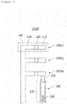
- FIG. 1 is a diagram schematically illustrating a multistage fuse according to an embodiment of the present invention.
- the multistage fuse 1000 may include a fuse module 100 and a contact terminal 200.
- the fuse module 100 may include a first fuse bar 110, a melted portion 120, and a second fuse bar 130.
- the first fuse bar 110 may be formed in a bar shape as a conductive member.
- the first fuse bar 110 is in direct contact with the contact terminal 200 to be described later and serves to allow current to flow between the second fuse bar and the contact terminal to be described later.
- the melted portion 120 may be a member that is melted when overcurrent flows. In general, a rated capacity of a fuse is determined according to physical characteristics of the melted portion 120. The melted portion 120 may serve to support the first fuse bar 110 before the overcurrent flows. However, since the melted portion 120 is melted when the overcurrent flows, the melted portion 120 may not serve to support the first fuse bar 110. Therefore, when the overcurrent flows to the melted portion 120, the melted portion 120 is melted, and as a result, the contact between the first fuse bar 110 and the contact terminal 200 is broken.
- the number of fuse modules 100 may be 2 or more.
- the existing fuse is fused (melted) by temporary overcurrent, and as a result, a entire system connected with the fuse may not be used.
- the system may be continuously used by using the other fuse module 100 without replacing the fuse.
- the current is momentarily interrupted and the entire system may be stopped by recognizing the current interruption by a battery control system (for example, BMS).
- BMS battery control system
- respective fuse modules 100 may have different rated capacities of the fused portions 120.
- the fuse module 100 (hereinafter referred to as a "first fuse module 100(a)") which is first connected with the contact terminal 200
- the fuse module 100 (hereinafter, referred to as a “second fuse module 100(b)”) which is connected with the contact terminal 200 when the first fuse module 100(a) is fused
- the fuse module 100 (hereinafter, referred to as a "third fuse module 100(c)”) connected with the contact terminal 200 when the second fuse module 100(b) is fused
- rated current levels of the respective fuse modules 100 may be variously set for the need of the user or efficient driving of the system.
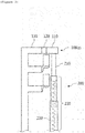
- FIGS. 2 and 3 are diagrams schematically illustrating a state in which melted portions 120 of some fuse modules 100 of the multistage fuse according to the embodiment of the present invention are melted and
- FIG. 4 is a diagram schematically illustrating a contact terminal 200 of the multistage fuse according to the embodiment of the present invention.
- the first fuse module 100(a) sets the rated current capacity to 100 A
- the second fuse module 100(b) sets the rated current capacity to 150 A
- the second fuse module 100(b) sets the rated current capacity to 200A
- the first fuse module 100(a) is fused and the contact terminal 200 is disconnected from the first module 100(a)
- the current is interrupted and thereafter, the contact terminal 200 contacts the first fuse bar 110 of the second fuse module 100(b)
- the current may flow on the system again as illustrated in FIG. 2 .
- the system is operated again only when the user inputs a reset signal by pressing a reset button. Thereafter, when the overcurrent of 150 A or more flows on the multistage fuse again, the second fuse module 100(b) is fused and the contact terminal 200 is disconnected from the second fuse module 100(b), and as a result, the current is interrupted and thereafter, the contact terminal 200 contacts the first fuse bar 110 of the third fuse module 100(c), and as a result, the current may flow on the system again as illustrated in FIG. 3 .
- the second fuse bar 130 may serve to support the melted portion 120.
- the second fuse bar 130 may be made of the same material as the first fuse bar 110, but may be made of another material.
- the second fuse bar 130 may be connected to another wire (not illustrated) or circuit (not illustrated) to allow the current to flow on the multistage fuse.
- the contact terminal 200 may contact the first fuse bar 110 by elastic force. More specifically, the contact terminal 200 may include a contact tip 210 and an elastic member.
- the contact tip 210 may be formed of a conductive member on which the current may flow and may contact the first fuse bar 110.
- the shape of the contact tip 210 is not particularly limited, but it is preferable that one portion of the contact tip 210 is formed in a long shape so that a part of the contact tip 210 may be accommodated in a contact support to be described later.
- the contact tip 210 may be formed in a cylindrical shape.
- the elastic member is a member having the elastic force due to a change in length, and may serve to push the contact tip 210 in the direction of the first fuse bar 110.
- the elastic member may be a spring 230.
- the contact terminal 200 may further include a contact support unit 220 accommodating a part of the contact tip 210 therein.
- the contact support unit 220 may serve to guide movement of the contact tip 210 by the elastic member.
- the contact support unit 220 is formed in the cylindrical shape to guide the contact tip 210 to move in the direction of the first fuse bar 110 by the elastic member.
- the contact support unit 220 may be formed of two or more members.
- the contact support unit 220 may be formed in a multistage structure including two or more members. For example, as illustrated in FIGS. 1 to 4 , the contact support unit 220 may be formed in a shape in which cylinders having different diameters are overlapped.
- the contact support unit 220 may include conductive circuits 222 and 224 which contact the contact tip 210 therein.
- the conductive circuits 222 and 224 may serve to allow the current to flow in connection with another wire (not illustrated) through contact with the contact tip 210.
- the contact support unit 220 may include a connection tip 225 connecting conductive circuits of the respective members.
- an outer portion of the contact support unit 220 may be formed by non-conductive members 221 and 223.
- the outer portion of the contact support unit 220 is formed by the non-conductive member to prevent the first fuse bar(s) 110 of the melted first fuse module 100(a) and/or the second fuse module 100(b) and the contact tip 210 from abnormally contacting each other.
Landscapes
- Fuses (AREA)
Abstract
Description
- This application claims priority to and the benefit of Korean Patent Application No.
10-2016-0086841 - The present invention relates to a multistage fuse, and more particularly, to a multistage fuse including: a fuse module including a first fuse bar formed in a bar shape as a conductive member; a melted portion which supports the first fuse bar and is melted when overcurrent flows; and a second fuse bar which supports the melted portion; and a contact terminal which contacts the first fuse bar by elastic force, so that even if any one fuse module is fused due to temporary overcurrent and the current is thus momentarily interrupted, the system can be continuously used by using the other fuse module without replacing the fuse.
- A fuse as a device that serves to protect a circuit or system by blocking overcurrent is widely used in most circuits for circuit protection for preventing secondary damage such as or fire. In general, the fuse has its unique rated current capacity, and the rated current capacity is determined by a metal component constituting the fuse.
- However, the fuse in the related art is fused by only transient surge current to interrupt current, so that a whole system can not be used until the fuse is replaced by interrupting the current. For example, if the overcurrent occurs in a battery system of an electric vehicle, and the fuse is fused, there is inconvenience that an automobile can not be used until the fuse is replaced at an auto shop. In addition, since one rated current capacity is determined for each fuse, it is impossible to limit the current at various levels according to the need of a user and a purpose or use of the system.
- Therefore, there is a growing need for researching fuses that have various rated current capacities and can perform overcurrent interruption operations several times.
- In order to solve the problem and an object of the present invention is to provide a multistage fuse which includes: a fuse module including a first fuse bar formed in a bar shape as a conductive member; a melted portion which supports the first fuse bar and is melted when overcurrent flows; and a second fuse bar which supports the melted portion; and a contact terminal which contacts the first fuse bar by elastic force and which allows each fuse module to have various rated current capacities to secure stepwise stability of a system and perform overcurrent interruption several times.
- A multistage fuse according to an embodiment of the present invention may include: a fuse module including a first fuse bar formed in a bar shape as a conductive member; a melted portion which supports the first fuse bar and is melted when overcurrent flows; and a second fuse bar which supports the melted portion; and a contact terminal which contacts the first fuse bar by elastic force, in which when the overcurrent flows on the melted portion, the melted portion is melted to disconnect the first fuse bar and the contact terminal.
- In the multistage fuse, the number of fuse modules may be 2 or more.
- In the fuse module, respective fuse modules may have different rated capacities of the melted portions.
- The contact terminal may include a contact tip formed by the conductive member and contacting the first fuse bar, and an elastic member pushing the contact tip in the direction of the first fuse bar.
- The contact tip may be formed in a cylindrical shape, and the contact terminal may further include a contact support unit accommodating a part of the contact tip therein.
- A conductive circuit contacting the contact tip may be formed in an inner portion of the contact support unit and an outer portion of the contact support unit may be formed by a non-conductive member.
- According to an embodiment of the present invention, even if any one fuse module is fused due to temporary overcurrent and the current is thus momentarily interrupted, a system can be continuously used by using the other fuse module without replacing the fuse and rated current levels of respective fuse modules can be variously set for the need of a user or efficient driving of the system.
-
-
FIG. 1 is a diagram schematically illustrating a multistage fuse according to an embodiment of the present invention. -
FIGS. 2 and3 are diagrams schematically illustrating a state in which melted portions of some fuse modules of the multistage fuse are melted according to the embodiment of the present invention. -
FIG. 4 is a diagram schematically illustrating a contact terminal of the multistage fuse according to the embodiment of the present invention. - The present invention will be described below in detail with reference to the accompanying drawings. Herein, the repeated description and the detailed description of publicly-known function and configuration that may make the gist of the present invention unnecessarily ambiguous will be omitted. Embodiments of the present invention are provided for more completely describing the present invention to those skilled in the art. Accordingly, shapes, sizes, and the like of elements in the drawings may be exaggerated for clearer explanation.
- Throughout the specification, unless explicitly described to the contrary, a case where any part "includes" any component will be understood to imply the inclusion of stated components but not the exclusion of any other component.
- In addition, the term "unit" disclosed in the specification means a unit that processes at least one function or operation, and the unit may be implemented by hardware or software or a combination of hardware and software.
-
FIG. 1 is a diagram schematically illustrating a multistage fuse according to an embodiment of the present invention. - Referring to
FIG. 1 , themultistage fuse 1000 according to the embodiment of the present invention may include afuse module 100 and acontact terminal 200. - The
fuse module 100 may include afirst fuse bar 110, a meltedportion 120, and asecond fuse bar 130. - The
first fuse bar 110 may be formed in a bar shape as a conductive member. Thefirst fuse bar 110 is in direct contact with thecontact terminal 200 to be described later and serves to allow current to flow between the second fuse bar and the contact terminal to be described later. - The melted
portion 120 may be a member that is melted when overcurrent flows. In general, a rated capacity of a fuse is determined according to physical characteristics of the meltedportion 120. The meltedportion 120 may serve to support thefirst fuse bar 110 before the overcurrent flows. However, since the meltedportion 120 is melted when the overcurrent flows, the meltedportion 120 may not serve to support thefirst fuse bar 110. Therefore, when the overcurrent flows to the meltedportion 120, the meltedportion 120 is melted, and as a result, the contact between thefirst fuse bar 110 and thecontact terminal 200 is broken. - The number of
fuse modules 100 may be 2 or more. The existing fuse is fused (melted) by temporary overcurrent, and as a result, a entire system connected with the fuse may not be used. However, in the multistage fuse according to the embodiment of the present invention, even if any onefuse module 100 is fused due to the temporary overcurrent and current is thus interrupted, the system may be continuously used by using theother fuse module 100 without replacing the fuse. In the multistage fuse according to the embodiment of the present invention, when fusing occurs due to the overcurrent, the current is momentarily interrupted and the entire system may be stopped by recognizing the current interruption by a battery control system (for example, BMS). Thereafter, when a user presses a reset button again, the system is restarted, and as a result, repetitive replacement of the fuse is minimized while maintaining an inherent function of the fuse by restarting the system, thereby preventing the system from being unnecessarily interrupted. - In the
fuse module 100,respective fuse modules 100 may have different rated capacities of the fusedportions 120. When the fuse module 100 (hereinafter referred to as a "first fuse module 100(a)") which is first connected with thecontact terminal 200, the fuse module 100 (hereinafter, referred to as a "second fuse module 100(b)") which is connected with thecontact terminal 200 when the first fuse module 100(a) is fused, and the fuse module 100 (hereinafter, referred to as a "third fuse module 100(c)") connected with thecontact terminal 200 when the second fuse module 100(b) is fused may be different from each other in rated capacity of the meltedportion 120. In this case, rated current levels of therespective fuse modules 100 may be variously set for the need of the user or efficient driving of the system. -
FIGS. 2 and3 are diagrams schematically illustrating a state in which meltedportions 120 of somefuse modules 100 of the multistage fuse according to the embodiment of the present invention are melted andFIG. 4 is a diagram schematically illustrating acontact terminal 200 of the multistage fuse according to the embodiment of the present invention. - For example, if the first fuse module 100(a) sets the rated current capacity to 100 A, the second fuse module 100(b) sets the rated current capacity to 150 A, and the second fuse module 100(b) sets the rated current capacity to 200A, when overcurrent of 100 A or more flows on the multistage fuse, the first fuse module 100(a) is fused and the
contact terminal 200 is disconnected from the first module 100(a), and as a result, the current is interrupted and thereafter, thecontact terminal 200 contacts thefirst fuse bar 110 of the second fuse module 100(b), and as a result, the current may flow on the system again as illustrated inFIG. 2 . In this case, once the current is interrupted by a control unit of the system, it is preferable that the system is operated again only when the user inputs a reset signal by pressing a reset button. Thereafter, when the overcurrent of 150 A or more flows on the multistage fuse again, the second fuse module 100(b) is fused and thecontact terminal 200 is disconnected from the second fuse module 100(b), and as a result, the current is interrupted and thereafter, thecontact terminal 200 contacts thefirst fuse bar 110 of the third fuse module 100(c), and as a result, the current may flow on the system again as illustrated inFIG. 3 . - When current of 200 A or more flows, the system is finally interrupted. Therefore, it is possible to continuously drive the system by minimizing the fuse replacement while ensuring the stability of the system step by step according to the need of the user or the purpose and usage of the system.
- The
second fuse bar 130 may serve to support the meltedportion 120. Thesecond fuse bar 130 may be made of the same material as thefirst fuse bar 110, but may be made of another material. Thesecond fuse bar 130 may be connected to another wire (not illustrated) or circuit (not illustrated) to allow the current to flow on the multistage fuse. - The
contact terminal 200 may contact thefirst fuse bar 110 by elastic force. More specifically, thecontact terminal 200 may include acontact tip 210 and an elastic member. - The
contact tip 210 may be formed of a conductive member on which the current may flow and may contact thefirst fuse bar 110. The shape of thecontact tip 210 is not particularly limited, but it is preferable that one portion of thecontact tip 210 is formed in a long shape so that a part of thecontact tip 210 may be accommodated in a contact support to be described later. As one example, thecontact tip 210 may be formed in a cylindrical shape. - The elastic member is a member having the elastic force due to a change in length, and may serve to push the
contact tip 210 in the direction of thefirst fuse bar 110. For example, the elastic member may be aspring 230. - The
contact terminal 200 may further include acontact support unit 220 accommodating a part of thecontact tip 210 therein. Thecontact support unit 220 may serve to guide movement of thecontact tip 210 by the elastic member. For example, when thecontact tip 210 is formed in the cylindrical shape, thecontact support unit 220 is formed in the cylindrical shape to guide thecontact tip 210 to move in the direction of thefirst fuse bar 110 by the elastic member. Further, thecontact support unit 220 may be formed of two or more members. Thecontact support unit 220 may be formed in a multistage structure including two or more members. For example, as illustrated inFIGS. 1 to 4 , thecontact support unit 220 may be formed in a shape in which cylinders having different diameters are overlapped. - Referring to
FIG. 4 , thecontact support unit 220 may includeconductive circuits contact tip 210 therein. Theconductive circuits contact tip 210. When thecontact support unit 220 is formed in the multistage structure including two or more members, thecontact support unit 220 may include aconnection tip 225 connecting conductive circuits of the respective members. - Further, an outer portion of the
contact support unit 220 may be formed bynon-conductive members first fuse bar 110 may be bent accurately in an orthogonal direction to thesecond fuse bar 130. Therefore, the outer portion of thecontact support unit 220 is formed by the non-conductive member to prevent the first fuse bar(s) 110 of the melted first fuse module 100(a) and/or the second fuse module 100(b) and thecontact tip 210 from abnormally contacting each other. - Hereinabove, a specific embodiment of the present invention has been illustrated and described, but the technical spirit of the present invention is not limited to the accompanying drawings and the described contents and it is apparent to those skilled in the art that various modifications of the present invention can be made within the scope without departing from the spirit of the present inventionand it will be regarded that the modifications are included in the claims of the present invention without departing from the spirit of the present invention.
Claims (6)
- A multistage fuse comprising:a fuse module including a first fuse bar formed in a bar shape as a conductive member; a melted portion which supports the first fuse bar and is melted when overcurrent flows; and a second fuse bar which supports the melted portion; anda contact terminal which contacts the first fuse bar by elastic force,wherein when the overcurrent flows on the melted portion, the melted portion is melted to disconnect the first fuse bar and the contact terminal.
- The multistage fuse of claim 1, wherein the number of fuse modules is 2 or more.
- The multistage fuse of claim 2, wherein in the fuse module, respective fuse modules have different rated capacities of the melted portions.
- The multistage fuse of claim 1, wherein the contact terminal includes
a contact tip formed by the conductive member and contacting the first fuse bar, and
an elastic member pushing the contact tip in the direction of the first fuse bar. - The multistage fuse of claim 4, wherein the contact tip is formed in a cylindrical shape, and
the contact terminal further includes a contact support unit accommodating a part of the contact tip therein. - The multistage fuse of claim 5, wherein a conductive circuit contacting the contact tip is formed in an inner portion of the contact support unit and an outer portion of the contact support unit is formed by a non-conductive member.
Priority Applications (1)
| Application Number | Priority Date | Filing Date | Title |
|---|---|---|---|
| PL17824546T PL3358595T3 (en) | 2016-07-08 | 2017-07-06 | Multistage fuse |
Applications Claiming Priority (2)
| Application Number | Priority Date | Filing Date | Title |
|---|---|---|---|
| KR1020160086841A KR102030883B1 (en) | 2016-07-08 | 2016-07-08 | Multi-type fuses |
| PCT/KR2017/007207 WO2018008990A1 (en) | 2016-07-08 | 2017-07-06 | Multistage fuse |
Publications (3)
| Publication Number | Publication Date |
|---|---|
| EP3358595A1 true EP3358595A1 (en) | 2018-08-08 |
| EP3358595A4 EP3358595A4 (en) | 2019-01-02 |
| EP3358595B1 EP3358595B1 (en) | 2021-09-01 |
Family
ID=60912987
Family Applications (1)
| Application Number | Title | Priority Date | Filing Date |
|---|---|---|---|
| EP17824546.0A Active EP3358595B1 (en) | 2016-07-08 | 2017-07-06 | Multistage fuse |
Country Status (7)
| Country | Link |
|---|---|
| US (1) | US10418218B2 (en) |
| EP (1) | EP3358595B1 (en) |
| JP (1) | JP6640344B2 (en) |
| KR (1) | KR102030883B1 (en) |
| CN (1) | CN108352280B (en) |
| PL (1) | PL3358595T3 (en) |
| WO (1) | WO2018008990A1 (en) |
Families Citing this family (4)
| Publication number | Priority date | Publication date | Assignee | Title |
|---|---|---|---|---|
| KR102442331B1 (en) * | 2018-05-25 | 2022-09-08 | 주식회사 엘지에너지솔루션 | Multistage fuse module |
| CN111508796B (en) * | 2020-04-23 | 2022-07-22 | 南京萨特科技发展有限公司 | Controllable fuse, fuse assembly and control method |
| CN112542367B (en) * | 2020-11-26 | 2022-09-27 | 国网河南省电力公司商丘供电公司 | Fuse for power distribution protection |
| CN113314390B (en) * | 2021-05-31 | 2022-11-01 | 广东电网有限责任公司 | Tertiary safety device of voltage transformer |
Family Cites Families (20)
| Publication number | Priority date | Publication date | Assignee | Title |
|---|---|---|---|---|
| US531355A (en) * | 1894-12-25 | Fuse-box | ||
| US772200A (en) * | 1904-04-04 | 1904-10-11 | Herbert G Addie | Device for replacing fuses. |
| US950389A (en) * | 1908-12-10 | 1910-02-22 | Walter L Green | Fuse-replacing device. |
| US1053096A (en) * | 1910-02-28 | 1913-02-11 | Johnston Mfg Company | Electric fuse and cut-out. |
| US1773983A (en) * | 1927-08-05 | 1930-08-26 | Foo Lee Sing | Magazine fuse |
| US1715799A (en) | 1928-04-13 | 1929-06-04 | Herbert A Taylor | Fuse block and lightning arrester |
| GB645793A (en) * | 1948-11-01 | 1950-11-08 | Leonard Thomas Delamare | Improvements in and relating to electric fuse-boxes |
| US2874248A (en) * | 1956-09-11 | 1959-02-17 | Gen Dynamics Corp | Multiple fuse |
| US5475357A (en) * | 1994-01-13 | 1995-12-12 | Chien; Ming-Chyan | Fuse assembly |
| US5861793A (en) * | 1996-04-29 | 1999-01-19 | Hatton; Ken W. | Re-settable fuse |
| KR19990019539U (en) | 1997-11-19 | 1999-06-15 | 정몽규 | Automatic restoration device in case of fuse short circuit |
| JP4014345B2 (en) | 2000-02-04 | 2007-11-28 | 株式会社ニデック | Plastic lens dyeing method and dyeing substrate |
| KR100933744B1 (en) | 2005-05-17 | 2009-12-24 | 삼창기업 주식회사 | Dual fuse unit |
| KR101435210B1 (en) | 2008-08-11 | 2014-08-28 | 현대자동차주식회사 | Multi-fuse |
| KR101062740B1 (en) | 2008-12-26 | 2011-09-06 | 주식회사 하이닉스반도체 | Fuse box and semiconductor integrated circuit device having same |
| CN102754179B (en) | 2010-02-05 | 2015-05-27 | 矢崎总业株式会社 | Fusible link unit |
| JP2013175389A (en) * | 2012-02-27 | 2013-09-05 | Auto Network Gijutsu Kenkyusho:Kk | Connector having overcurrent interrupting function |
| JP2013237093A (en) | 2012-05-17 | 2013-11-28 | Toshiba Corp | Sand mold casting plan producing system, program, sand mold casting plan producing method, and casting |
| US8949617B2 (en) | 2013-05-03 | 2015-02-03 | Citrix Systems, Inc. | Disrupting password attack using compression |
| KR101669905B1 (en) * | 2014-10-31 | 2016-10-27 | 엘에스산전 주식회사 | Fuse striker link auto return structure in ring main unit |
-
2016
- 2016-07-08 KR KR1020160086841A patent/KR102030883B1/en active Active
-
2017
- 2017-07-06 JP JP2018521123A patent/JP6640344B2/en active Active
- 2017-07-06 WO PCT/KR2017/007207 patent/WO2018008990A1/en not_active Ceased
- 2017-07-06 PL PL17824546T patent/PL3358595T3/en unknown
- 2017-07-06 US US15/775,274 patent/US10418218B2/en active Active
- 2017-07-06 CN CN201780003962.4A patent/CN108352280B/en active Active
- 2017-07-06 EP EP17824546.0A patent/EP3358595B1/en active Active
Also Published As
| Publication number | Publication date |
|---|---|
| JP2018531499A (en) | 2018-10-25 |
| US20180323029A1 (en) | 2018-11-08 |
| JP6640344B2 (en) | 2020-02-05 |
| EP3358595B1 (en) | 2021-09-01 |
| WO2018008990A1 (en) | 2018-01-11 |
| PL3358595T3 (en) | 2021-12-20 |
| CN108352280B (en) | 2019-11-05 |
| EP3358595A4 (en) | 2019-01-02 |
| KR20180006131A (en) | 2018-01-17 |
| CN108352280A (en) | 2018-07-31 |
| KR102030883B1 (en) | 2019-10-10 |
| US10418218B2 (en) | 2019-09-17 |
Similar Documents
| Publication | Publication Date | Title |
|---|---|---|
| EP3358595B1 (en) | Multistage fuse | |
| CN101752140B (en) | Tulip contacting device of vacuum circuit breaker | |
| US8830024B2 (en) | Device for receiving a fuse and switching device | |
| JP2017117565A (en) | Manufacturing method for fuse, and fuse | |
| EP3138663A1 (en) | Battery pack and electrical combination | |
| CN111052291B (en) | DC Circuit Interrupting Switch Assemblies | |
| KR102385996B1 (en) | Busbar of battery pack of eco-friendly vehicles having fusing function and battery pack of eco-friendly vehicles using the same | |
| JP2018531499A6 (en) | Multistage fuse | |
| US7345568B2 (en) | Dual protection device for circuits | |
| CA2911299C (en) | Circuit breakers with common trip cams and related trip cams | |
| JP2018129309A (en) | Manufacturing method for fuse, and fuse | |
| KR102395481B1 (en) | Rechargeable battery | |
| JP2015088315A (en) | Battery device and circuit cut-off structure | |
| US10063016B2 (en) | Fuse protected socket having additional attachment points | |
| CN104246959A (en) | Fuse | |
| JP2018026202A (en) | fuse | |
| US9287663B1 (en) | Electrical connector and method of electrically coupling first and second electrical terminals of first and second battery cells to one another | |
| JP7023270B2 (en) | Fuse carrier and disconnector module | |
| KR20170003589U (en) | Tulip contacts structure of vacuum circuit breaker | |
| CN108155508B (en) | Terminal assembly for vacuum contactor switch | |
| KR102442331B1 (en) | Multistage fuse module | |
| US11128107B2 (en) | Electrical protection component having a thermal short-circuit device | |
| KR20180064015A (en) | Circuit breaker | |
| CN109416990A (en) | Shock Resistant Electrical Switch | |
| JP6854615B2 (en) | Current cutoff structure and electrical junction box with it |
Legal Events
| Date | Code | Title | Description |
|---|---|---|---|
| STAA | Information on the status of an ep patent application or granted ep patent |
Free format text: STATUS: THE INTERNATIONAL PUBLICATION HAS BEEN MADE |
|
| PUAI | Public reference made under article 153(3) epc to a published international application that has entered the european phase |
Free format text: ORIGINAL CODE: 0009012 |
|
| STAA | Information on the status of an ep patent application or granted ep patent |
Free format text: STATUS: REQUEST FOR EXAMINATION WAS MADE |
|
| 17P | Request for examination filed |
Effective date: 20180504 |
|
| AK | Designated contracting states |
Kind code of ref document: A1 Designated state(s): AL AT BE BG CH CY CZ DE DK EE ES FI FR GB GR HR HU IE IS IT LI LT LU LV MC MK MT NL NO PL PT RO RS SE SI SK SM TR |
|
| AX | Request for extension of the european patent |
Extension state: BA ME |
|
| A4 | Supplementary search report drawn up and despatched |
Effective date: 20181203 |
|
| RIC1 | Information provided on ipc code assigned before grant |
Ipc: H01R 13/24 20060101ALI20181127BHEP Ipc: H01H 85/055 20060101ALI20181127BHEP Ipc: H01H 85/28 20060101ALI20181127BHEP Ipc: H01H 85/08 20060101ALI20181127BHEP Ipc: H01H 85/20 20060101AFI20181127BHEP |
|
| DAV | Request for validation of the european patent (deleted) | ||
| DAX | Request for extension of the european patent (deleted) | ||
| GRAP | Despatch of communication of intention to grant a patent |
Free format text: ORIGINAL CODE: EPIDOSNIGR1 |
|
| STAA | Information on the status of an ep patent application or granted ep patent |
Free format text: STATUS: GRANT OF PATENT IS INTENDED |
|
| RIC1 | Information provided on ipc code assigned before grant |
Ipc: H01H 85/28 20060101ALI20210303BHEP Ipc: H01H 85/055 20060101ALI20210303BHEP Ipc: H01R 13/24 20060101ALI20210303BHEP Ipc: H01H 85/20 20060101AFI20210303BHEP Ipc: H01H 85/08 20060101ALI20210303BHEP |
|
| INTG | Intention to grant announced |
Effective date: 20210323 |
|
| GRAS | Grant fee paid |
Free format text: ORIGINAL CODE: EPIDOSNIGR3 |
|
| GRAA | (expected) grant |
Free format text: ORIGINAL CODE: 0009210 |
|
| STAA | Information on the status of an ep patent application or granted ep patent |
Free format text: STATUS: THE PATENT HAS BEEN GRANTED |
|
| AK | Designated contracting states |
Kind code of ref document: B1 Designated state(s): AL AT BE BG CH CY CZ DE DK EE ES FI FR GB GR HR HU IE IS IT LI LT LU LV MC MK MT NL NO PL PT RO RS SE SI SK SM TR |
|
| REG | Reference to a national code |
Ref country code: GB Ref legal event code: FG4D |
|
| REG | Reference to a national code |
Ref country code: CH Ref legal event code: EP Ref country code: AT Ref legal event code: REF Ref document number: 1427099 Country of ref document: AT Kind code of ref document: T Effective date: 20210915 |
|
| REG | Reference to a national code |
Ref country code: DE Ref legal event code: R096 Ref document number: 602017045345 Country of ref document: DE |
|
| REG | Reference to a national code |
Ref country code: IE Ref legal event code: FG4D |
|
| REG | Reference to a national code |
Ref country code: SE Ref legal event code: TRGR |
|
| REG | Reference to a national code |
Ref country code: LT Ref legal event code: MG9D |
|
| REG | Reference to a national code |
Ref country code: NL Ref legal event code: MP Effective date: 20210901 |
|
| RAP2 | Party data changed (patent owner data changed or rights of a patent transferred) |
Owner name: LG ENERGY SOLUTION LTD. |
|
| PG25 | Lapsed in a contracting state [announced via postgrant information from national office to epo] |
Ref country code: NO Free format text: LAPSE BECAUSE OF FAILURE TO SUBMIT A TRANSLATION OF THE DESCRIPTION OR TO PAY THE FEE WITHIN THE PRESCRIBED TIME-LIMIT Effective date: 20211201 Ref country code: LT Free format text: LAPSE BECAUSE OF FAILURE TO SUBMIT A TRANSLATION OF THE DESCRIPTION OR TO PAY THE FEE WITHIN THE PRESCRIBED TIME-LIMIT Effective date: 20210901 Ref country code: BG Free format text: LAPSE BECAUSE OF FAILURE TO SUBMIT A TRANSLATION OF THE DESCRIPTION OR TO PAY THE FEE WITHIN THE PRESCRIBED TIME-LIMIT Effective date: 20211201 Ref country code: RS Free format text: LAPSE BECAUSE OF FAILURE TO SUBMIT A TRANSLATION OF THE DESCRIPTION OR TO PAY THE FEE WITHIN THE PRESCRIBED TIME-LIMIT Effective date: 20210901 Ref country code: HR Free format text: LAPSE BECAUSE OF FAILURE TO SUBMIT A TRANSLATION OF THE DESCRIPTION OR TO PAY THE FEE WITHIN THE PRESCRIBED TIME-LIMIT Effective date: 20210901 Ref country code: FI Free format text: LAPSE BECAUSE OF FAILURE TO SUBMIT A TRANSLATION OF THE DESCRIPTION OR TO PAY THE FEE WITHIN THE PRESCRIBED TIME-LIMIT Effective date: 20210901 Ref country code: ES Free format text: LAPSE BECAUSE OF FAILURE TO SUBMIT A TRANSLATION OF THE DESCRIPTION OR TO PAY THE FEE WITHIN THE PRESCRIBED TIME-LIMIT Effective date: 20210901 |
|
| REG | Reference to a national code |
Ref country code: AT Ref legal event code: MK05 Ref document number: 1427099 Country of ref document: AT Kind code of ref document: T Effective date: 20210901 |
|
| PG25 | Lapsed in a contracting state [announced via postgrant information from national office to epo] |
Ref country code: LV Free format text: LAPSE BECAUSE OF FAILURE TO SUBMIT A TRANSLATION OF THE DESCRIPTION OR TO PAY THE FEE WITHIN THE PRESCRIBED TIME-LIMIT Effective date: 20210901 Ref country code: GR Free format text: LAPSE BECAUSE OF FAILURE TO SUBMIT A TRANSLATION OF THE DESCRIPTION OR TO PAY THE FEE WITHIN THE PRESCRIBED TIME-LIMIT Effective date: 20211202 |
|
| RAP4 | Party data changed (patent owner data changed or rights of a patent transferred) |
Owner name: LG ENERGY SOLUTION, LTD. |
|
| PG25 | Lapsed in a contracting state [announced via postgrant information from national office to epo] |
Ref country code: AT Free format text: LAPSE BECAUSE OF FAILURE TO SUBMIT A TRANSLATION OF THE DESCRIPTION OR TO PAY THE FEE WITHIN THE PRESCRIBED TIME-LIMIT Effective date: 20210901 |
|
| PG25 | Lapsed in a contracting state [announced via postgrant information from national office to epo] |
Ref country code: IS Free format text: LAPSE BECAUSE OF FAILURE TO SUBMIT A TRANSLATION OF THE DESCRIPTION OR TO PAY THE FEE WITHIN THE PRESCRIBED TIME-LIMIT Effective date: 20220101 Ref country code: SM Free format text: LAPSE BECAUSE OF FAILURE TO SUBMIT A TRANSLATION OF THE DESCRIPTION OR TO PAY THE FEE WITHIN THE PRESCRIBED TIME-LIMIT Effective date: 20210901 Ref country code: SK Free format text: LAPSE BECAUSE OF FAILURE TO SUBMIT A TRANSLATION OF THE DESCRIPTION OR TO PAY THE FEE WITHIN THE PRESCRIBED TIME-LIMIT Effective date: 20210901 Ref country code: RO Free format text: LAPSE BECAUSE OF FAILURE TO SUBMIT A TRANSLATION OF THE DESCRIPTION OR TO PAY THE FEE WITHIN THE PRESCRIBED TIME-LIMIT Effective date: 20210901 Ref country code: PT Free format text: LAPSE BECAUSE OF FAILURE TO SUBMIT A TRANSLATION OF THE DESCRIPTION OR TO PAY THE FEE WITHIN THE PRESCRIBED TIME-LIMIT Effective date: 20220103 Ref country code: NL Free format text: LAPSE BECAUSE OF FAILURE TO SUBMIT A TRANSLATION OF THE DESCRIPTION OR TO PAY THE FEE WITHIN THE PRESCRIBED TIME-LIMIT Effective date: 20210901 Ref country code: EE Free format text: LAPSE BECAUSE OF FAILURE TO SUBMIT A TRANSLATION OF THE DESCRIPTION OR TO PAY THE FEE WITHIN THE PRESCRIBED TIME-LIMIT Effective date: 20210901 Ref country code: CZ Free format text: LAPSE BECAUSE OF FAILURE TO SUBMIT A TRANSLATION OF THE DESCRIPTION OR TO PAY THE FEE WITHIN THE PRESCRIBED TIME-LIMIT Effective date: 20210901 Ref country code: AL Free format text: LAPSE BECAUSE OF FAILURE TO SUBMIT A TRANSLATION OF THE DESCRIPTION OR TO PAY THE FEE WITHIN THE PRESCRIBED TIME-LIMIT Effective date: 20210901 |
|
| REG | Reference to a national code |
Ref country code: DE Ref legal event code: R097 Ref document number: 602017045345 Country of ref document: DE |
|
| PLBE | No opposition filed within time limit |
Free format text: ORIGINAL CODE: 0009261 |
|
| STAA | Information on the status of an ep patent application or granted ep patent |
Free format text: STATUS: NO OPPOSITION FILED WITHIN TIME LIMIT |
|
| PG25 | Lapsed in a contracting state [announced via postgrant information from national office to epo] |
Ref country code: IT Free format text: LAPSE BECAUSE OF FAILURE TO SUBMIT A TRANSLATION OF THE DESCRIPTION OR TO PAY THE FEE WITHIN THE PRESCRIBED TIME-LIMIT Effective date: 20210901 Ref country code: DK Free format text: LAPSE BECAUSE OF FAILURE TO SUBMIT A TRANSLATION OF THE DESCRIPTION OR TO PAY THE FEE WITHIN THE PRESCRIBED TIME-LIMIT Effective date: 20210901 |
|
| 26N | No opposition filed |
Effective date: 20220602 |
|
| PG25 | Lapsed in a contracting state [announced via postgrant information from national office to epo] |
Ref country code: SI Free format text: LAPSE BECAUSE OF FAILURE TO SUBMIT A TRANSLATION OF THE DESCRIPTION OR TO PAY THE FEE WITHIN THE PRESCRIBED TIME-LIMIT Effective date: 20210901 |
|
| PG25 | Lapsed in a contracting state [announced via postgrant information from national office to epo] |
Ref country code: MC Free format text: LAPSE BECAUSE OF FAILURE TO SUBMIT A TRANSLATION OF THE DESCRIPTION OR TO PAY THE FEE WITHIN THE PRESCRIBED TIME-LIMIT Effective date: 20210901 |
|
| REG | Reference to a national code |
Ref country code: CH Ref legal event code: PL |
|
| REG | Reference to a national code |
Ref country code: BE Ref legal event code: MM Effective date: 20220731 |
|
| PG25 | Lapsed in a contracting state [announced via postgrant information from national office to epo] |
Ref country code: LU Free format text: LAPSE BECAUSE OF NON-PAYMENT OF DUE FEES Effective date: 20220706 Ref country code: LI Free format text: LAPSE BECAUSE OF NON-PAYMENT OF DUE FEES Effective date: 20220731 Ref country code: CH Free format text: LAPSE BECAUSE OF NON-PAYMENT OF DUE FEES Effective date: 20220731 |
|
| REG | Reference to a national code |
Ref country code: DE Ref legal event code: R081 Ref document number: 602017045345 Country of ref document: DE Owner name: LG ENERGY SOLUTION, LTD., KR Free format text: FORMER OWNER: LG CHEM, LTD., SEOUL, KR |
|
| PG25 | Lapsed in a contracting state [announced via postgrant information from national office to epo] |
Ref country code: BE Free format text: LAPSE BECAUSE OF NON-PAYMENT OF DUE FEES Effective date: 20220731 |
|
| P01 | Opt-out of the competence of the unified patent court (upc) registered |
Effective date: 20230512 |
|
| PG25 | Lapsed in a contracting state [announced via postgrant information from national office to epo] |
Ref country code: IE Free format text: LAPSE BECAUSE OF NON-PAYMENT OF DUE FEES Effective date: 20220706 |
|
| REG | Reference to a national code |
Ref country code: GB Ref legal event code: 732E Free format text: REGISTERED BETWEEN 20230901 AND 20230906 |
|
| PG25 | Lapsed in a contracting state [announced via postgrant information from national office to epo] |
Ref country code: HU Free format text: LAPSE BECAUSE OF FAILURE TO SUBMIT A TRANSLATION OF THE DESCRIPTION OR TO PAY THE FEE WITHIN THE PRESCRIBED TIME-LIMIT; INVALID AB INITIO Effective date: 20170706 |
|
| PG25 | Lapsed in a contracting state [announced via postgrant information from national office to epo] |
Ref country code: MK Free format text: LAPSE BECAUSE OF FAILURE TO SUBMIT A TRANSLATION OF THE DESCRIPTION OR TO PAY THE FEE WITHIN THE PRESCRIBED TIME-LIMIT Effective date: 20210901 Ref country code: CY Free format text: LAPSE BECAUSE OF FAILURE TO SUBMIT A TRANSLATION OF THE DESCRIPTION OR TO PAY THE FEE WITHIN THE PRESCRIBED TIME-LIMIT Effective date: 20210901 |
|
| PG25 | Lapsed in a contracting state [announced via postgrant information from national office to epo] |
Ref country code: TR Free format text: LAPSE BECAUSE OF FAILURE TO SUBMIT A TRANSLATION OF THE DESCRIPTION OR TO PAY THE FEE WITHIN THE PRESCRIBED TIME-LIMIT Effective date: 20210901 |
|
| PG25 | Lapsed in a contracting state [announced via postgrant information from national office to epo] |
Ref country code: MT Free format text: LAPSE BECAUSE OF FAILURE TO SUBMIT A TRANSLATION OF THE DESCRIPTION OR TO PAY THE FEE WITHIN THE PRESCRIBED TIME-LIMIT Effective date: 20210901 |
|
| PGFP | Annual fee paid to national office [announced via postgrant information from national office to epo] |
Ref country code: SE Payment date: 20250624 Year of fee payment: 9 |
|
| PGFP | Annual fee paid to national office [announced via postgrant information from national office to epo] |
Ref country code: DE Payment date: 20250624 Year of fee payment: 9 |
|
| PGFP | Annual fee paid to national office [announced via postgrant information from national office to epo] |
Ref country code: GB Payment date: 20260624 Year of fee payment: 10 Ref country code: PL Payment date: 20260623 Year of fee payment: 10 |
|
| PGFP | Annual fee paid to national office [announced via postgrant information from national office to epo] |
Ref country code: FR Payment date: 20260625 Year of fee payment: 10 |