EP3358582A1 - Reciprocating electromagnetic actuator with flux-balanced armature and stationary cores - Google Patents
Reciprocating electromagnetic actuator with flux-balanced armature and stationary cores Download PDFInfo
- Publication number
- EP3358582A1 EP3358582A1 EP18154671.4A EP18154671A EP3358582A1 EP 3358582 A1 EP3358582 A1 EP 3358582A1 EP 18154671 A EP18154671 A EP 18154671A EP 3358582 A1 EP3358582 A1 EP 3358582A1
- Authority
- EP
- European Patent Office
- Prior art keywords
- stationary
- cores
- stationary cores
- annular
- ferromagnetic armature
- Prior art date
- Legal status (The legal status is an assumption and is not a legal conclusion. Google has not performed a legal analysis and makes no representation as to the accuracy of the status listed.)
- Granted
Links
Images


Classifications
-
- H—ELECTRICITY
- H01—ELECTRIC ELEMENTS
- H01F—MAGNETS; INDUCTANCES; TRANSFORMERS; SELECTION OF MATERIALS FOR THEIR MAGNETIC PROPERTIES
- H01F7/00—Magnets
- H01F7/06—Electromagnets; Actuators including electromagnets
- H01F7/08—Electromagnets; Actuators including electromagnets with armatures
- H01F7/081—Magnetic constructions
-
- H—ELECTRICITY
- H02—GENERATION; CONVERSION OR DISTRIBUTION OF ELECTRIC POWER
- H02K—DYNAMO-ELECTRIC MACHINES
- H02K33/00—Motors with reciprocating, oscillating or vibrating magnet, armature or coil system
- H02K33/12—Motors with reciprocating, oscillating or vibrating magnet, armature or coil system with armatures moving in alternate directions by alternate energisation of two coil systems
-
- F—MECHANICAL ENGINEERING; LIGHTING; HEATING; WEAPONS; BLASTING
- F01—MACHINES OR ENGINES IN GENERAL; ENGINE PLANTS IN GENERAL; STEAM ENGINES
- F01L—CYCLICALLY OPERATING VALVES FOR MACHINES OR ENGINES
- F01L9/00—Valve-gear or valve arrangements actuated non-mechanically
- F01L9/20—Valve-gear or valve arrangements actuated non-mechanically by electric means
-
- H—ELECTRICITY
- H01—ELECTRIC ELEMENTS
- H01F—MAGNETS; INDUCTANCES; TRANSFORMERS; SELECTION OF MATERIALS FOR THEIR MAGNETIC PROPERTIES
- H01F7/00—Magnets
- H01F7/06—Electromagnets; Actuators including electromagnets
- H01F7/08—Electromagnets; Actuators including electromagnets with armatures
- H01F7/16—Rectilinearly-movable armatures
- H01F7/1638—Armatures not entering the winding
-
- H—ELECTRICITY
- H02—GENERATION; CONVERSION OR DISTRIBUTION OF ELECTRIC POWER
- H02K—DYNAMO-ELECTRIC MACHINES
- H02K1/00—Details of the magnetic circuit
- H02K1/06—Details of the magnetic circuit characterised by the shape, form or construction
- H02K1/12—Stationary parts of the magnetic circuit
-
- H—ELECTRICITY
- H02—GENERATION; CONVERSION OR DISTRIBUTION OF ELECTRIC POWER
- H02K—DYNAMO-ELECTRIC MACHINES
- H02K1/00—Details of the magnetic circuit
- H02K1/06—Details of the magnetic circuit characterised by the shape, form or construction
- H02K1/34—Reciprocating, oscillating or vibrating parts of the magnetic circuit
-
- F—MECHANICAL ENGINEERING; LIGHTING; HEATING; WEAPONS; BLASTING
- F01—MACHINES OR ENGINES IN GENERAL; ENGINE PLANTS IN GENERAL; STEAM ENGINES
- F01L—CYCLICALLY OPERATING VALVES FOR MACHINES OR ENGINES
- F01L9/00—Valve-gear or valve arrangements actuated non-mechanically
- F01L9/20—Valve-gear or valve arrangements actuated non-mechanically by electric means
- F01L9/21—Valve-gear or valve arrangements actuated non-mechanically by electric means actuated by solenoids
- F01L2009/2105—Valve-gear or valve arrangements actuated non-mechanically by electric means actuated by solenoids comprising two or more coils
- F01L2009/2107—Valve-gear or valve arrangements actuated non-mechanically by electric means actuated by solenoids comprising two or more coils being disposed coaxially to the armature shaft
-
- H—ELECTRICITY
- H01—ELECTRIC ELEMENTS
- H01F—MAGNETS; INDUCTANCES; TRANSFORMERS; SELECTION OF MATERIALS FOR THEIR MAGNETIC PROPERTIES
- H01F7/00—Magnets
- H01F7/06—Electromagnets; Actuators including electromagnets
- H01F7/08—Electromagnets; Actuators including electromagnets with armatures
- H01F7/081—Magnetic constructions
- H01F2007/086—Structural details of the armature
-
- H—ELECTRICITY
- H01—ELECTRIC ELEMENTS
- H01F—MAGNETS; INDUCTANCES; TRANSFORMERS; SELECTION OF MATERIALS FOR THEIR MAGNETIC PROPERTIES
- H01F7/00—Magnets
- H01F7/06—Electromagnets; Actuators including electromagnets
- H01F7/08—Electromagnets; Actuators including electromagnets with armatures
- H01F7/16—Rectilinearly-movable armatures
- H01F2007/1692—Electromagnets or actuators with two coils
Definitions
- Exemplary embodiments pertain to the art of electromagnetic actuators, and more particularly, to reciprocating electromagnetic actuators with a flux-balanced armature and stationary cores.
- Electromagnetic linear actuators convert electrical energy into mechanical energy expressed as translatory motion. Electromagnetic actuators can be classified as electric motor driven actuators, solenoid actuators, and moving coil actuators. Reciprocating motion is a repetitive up-and-down or back-and-forth linear motion. Electromagnetic linear actuators are found in a wide range of mechanisms including reciprocating valves, engines and pumps. Reciprocating linear actuators that reciprocate an armature with permanent magnets (PMs) may not maximize force density (force per mass or per volume). PM actuators can be cost prohibitive for some applications and can experience higher rates of malfunction. For example, the operating temperature of PM devices may be limited and can be dependent on the grade of the PM material. Furthermore, PM devices can become demagnetized with time due to repetitive impact stationary armature-stationary core.
- PMs permanent magnets
- the armature shape may also provide limitations.
- armatures of some actuators with a uniform or flat surface may not provide adequate magnetic flux control that provide actuation forces needed for some applications.
- an apparatus for electromagnetic actuation includes a cylindrical housing.
- the apparatus further includes at least two stationary cores fixed to the cylindrical housing.
- Each stationary core includes at least one first annular portion having a first annular thickness between a first inner diameter and a first outer diameter.
- the apparatus further includes a ring coil fixed to and in operable communication with each of the at least two stationary cores.
- the apparatus further includes a ferromagnetic armature concentrically aligned with the at least two stationary cores and configured to move relative to the at least two stationary cores.
- the ferromagnetic armature has at least one second annular portion having a second annular thickness between a second inner diameter and a second outer diameter. The second annular thickness is about the same as the first annular thickness.
- an apparatus for electromagnetic actuation in another embodiment, includes a cylindrical housing.
- the apparatus further includes at least two stationary cores fixed to the cylindrical housing.
- Each stationary core includes at least one first annular portion having a first annular thickness between a first inner diameter and a first outer diameter.
- the apparatus further includes a ring coil fixed to and in operable communication with each of the at least two stationary cores.
- the ring coil includes a pair of stationary windings and having an inner diameter and an outer diameter.
- the apparatus further includes a ferromagnetic armature concentrically aligned with the at least two stationary cores and configured to move relative to the at least two stationary cores.
- the ferromagnetic armature has at least one second annular portion having a second annular thickness between a second inner diameter and a second outer diameter. The second annular thickness is about the same as the first annular thickness.
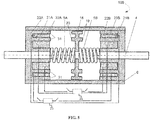
- FIG. 1 depicts a cross-sectional view of an electromagnetic actuator 100 (hereafter "actuator 100").
- Actuator 100 includes a pair of stationary cores 1A and 1B, a pair of ring coils 2A and 2B, a ferromagnetic armature 3, a rod 4, a pair of biasing members (e.g., return springs 5A and 5B), a cylindrical housing 6, and a power source 12 configured to switch power to ring coils 2A and 2B (alternately), and power stationary cores 1A and 1B simultaneously.
- biasing members e.g., return springs 5A and 5B
- Stationary cores 1A and 1B are electromagnets that can be configured on an opposite end of cylindrical housing 6 such that their poles face the center of the device toward ferromagnetic armature 3. Accordingly, stationary cores 1A and 1B are constructed of ferromagnetic material such as steel or soft magnetic composite material (SMC). Although two stationary cores 1A and 1B are shown, it is appreciated that actuator 100 may include any number of cores configured similarly as stationary cores 1A and 1B.
- Cylindrical housing 6 is configured to surround stationary cores 1A and 1B, and may be constructed of ferromagnetic material such as steel, or non-ferromagnetic material (e.g., aluminum).
- Rod 4 is rigidly fixed to ferromagnetic armature 3.
- Rod 4 may be constructed of a ferromagnetic material.
- rod 4 is constructed of brass or another non-ferromagnetic material to prevent wear and reduce mechanical friction of the core-rod.
- Ring coils 2A and 2B are ring shaped coils operatively connectable to a power source 12 and configured to be independently energized by the power source 12. Ring coils 2A and 2B are constructed of current-conducting wires such as copper or aluminum. Coils 2A and 2B can be also wound using copper or aluminum ribbon. Ring coil 2A is rigidly fixed to stationary core 1A in a pocket having the same shape as ring coil 2A. Coil 2B is rigidly fixed to stationary core 1B in a pocket having the same shape as the ring coil 2B.
- Actuator 100 includes a ferromagnetic armature 3 configured between stationary cores 1A and 1B.
- FIG. 2 depicts a section view and top view of ferromagnetic armature 3.
- ferromagnetic armature 3 is concentrically fixed to rod 4 (omitted in FIG. 3 for clarity) at center point 10, and configured to reciprocate in an interior of the cylindrical housing 6 between ring coils 2A and 2B.
- Return springs 5A and 5B are configured to bias ferromagnetic armature 3 away from stationary cores 1A and 1B.
- ferromagnetic armature 3 is configured to move back and forth axially in a reciprocal motion, counter to the force of return springs 5A and 5B. Reciprocation, as explained hereafter, occurs in response to introduction of a power source (not shown) operatively connected to stationary cores 1A and 1B which function as electromagnets.
- a power source not shown
- stationary cores 1A and 1B When stationary cores 1A and 1B are energized one after another, they produce the electromagnetic forces to move ferromagnetic armature 3 back and forth, which actuates rod 6.
- the shape of ferromagnetic armature 3 maximizes the magnetic flux and consequently maximize the attraction force between the armature and ferromagnetic cores 1A and 1B.
- ferromagnetic armature 3 includes an outside diameter 35.
- Ferromagnetic armature 3 includes a first face 8 opposing a second face 9. Faces 8 and 9 of ferromagnetic armature 3 each include a cylindrical recess that forms an interior recess wall 11.
- the cylindrical recess i.e., cup
- the interior recess wall 11 and the outer diameter 35 of ferromagnetic armature 3 form a cylindrical wall having a dimension (or thickness) (dimension 14) that generally matches a thickness of a matching annular portion on the stationary cores.
- Ferromagnetic armature 3 is concentrically aligned with the at least two stationary cores 1A and 1B. In some aspects, ferromagnetic armature 3 is configured to move relative to stationary cores 1A and 1B. Ferromagnetic armature 3 includes at least one annular portion 29 having an annular thickness 14 between an inner diameter 24 and an outer diameter 35. In some aspects, the annular thickness 14 being about the same as the annular thickness 15 described hereafter with respect to FIG. 3 .
- FIG. 3 depicts a stationary core 1A.
- actuator 100 includes at least two stationary cores (e.g., stationary core 1A) fixed to the cylindrical housing 6.
- each stationary core 1A includes at least one annular portion having an annular thickness 15 between an inner diameter 36 and an outer diameter 27.
- Thickness 15 is configured to be annularly aligned with dimension 14 of ferromagnetic armature 3.
- dimensions 14 (as shown in FIG. 2 ) may be substantially similar to or identical to dimension 15 (as shown in FIG. 3 ) within a predetermined tolerance of difference
- dimension 24 may be substantially similar to or identical to dimension 26, within a predetermined tolerance of difference.
- Thickness 15 may be smaller or greater than thickness 14 dependent on what shape of the force versus gap (displacement) characteristic is required.
- a predetermined tolerance may be 1%, for example. In another embodiment, the predetermined tolerance may be 2%, or 5%, or 10% difference between dimensions.
- first face 8 and second face 9 of armature 3 may correspond to portions of stationary cores 1A and 1B such that dimensions 14 and 15 are aligned when assembled within the predetermined tolerance.
- the magnetic flux lines are concentrated in the air gap between the stationary part and moving armature. If the armature is flat (e.g., without cup recesses) some of the magnetic flux may freely penetrate a surface of the moving armature located radially inwardly of the portion 30 of the stationary cores 1A and 1B.
- Stationary cores 1A and 1B are geometrically similar within the predetermined tolerance of difference.
- magnetic flux is configured to provide a high force density (force per mass or per volume) as compared to a ferromagnetic armature having flat faces 8 and 9 without twin cups.
- dimension 25 may be smaller than dimension 27 by a marginal amount to allow a slip fit or clearance between the inside diameter of housing 6 and dimension 25 (the outside diameter) of armature 3.
- FIG. 4 depicts an actuator 400 having return springs 5A and 5B positioned against a bottom wall of spring covers 7A and 7B, between a flanges 16 and 17, which are rigidly configured on each end of rod 4.
- Spring covers 7A and 7B are rigidly fixed to cylindrical housing 6.
- FIG. 5 depicts an actuator 500 having an armature 18 with two steps 19 and 20, and two stationary cores 23A and 23B, respectively, each having two annular portions 31 respectively matching steps 19 and 20, according to one embodiment.
- Actuator 500 may include two coils per core: 21A and 22A for stationary core 23A, and two coils 21B and 22B for stationary core 23B.
- armature 18 has two annular portions 19 and 20, which maximize magnetic flux in configurations having two magnetic cores (e.g., 21A and 22A) at each end of the actuator.
- the configuration of armature 18 is geometrically similar with respect to the corresponding portions of stationary cores 23A and 23B as described with respect to FIGS.
- Stationary core 23B may be substantially similar to stationary core 23A, and have annular portions facing annular portion 19 of armature 18.
- the benefits for the configuration of actuator 500 are at least twofold: First, having two coils in each magnetic core provides precise control of magnetic flux, and consequently, precise control of the attraction force that actuates rod 4. Second, the magnitude of magnetic flux may be controlled precisely by controlling the direction of each of the respective power sources operatively connected to the coils.
- the two coils 21A and 22A, and 21B and 22B, respectively can be fed form separate power sources 25 and 26. Each of power sources 25 and 26 can be independently controllable.
- Inner cylindrical coils 21A and 21B can be connected in series or in parallel.
- outer coils 22A and 22B can be connected in series or in parallel.
- the power source 26 energizes the inner coils 21A and 21B.
- the power source 25 energizes the outer coils 22A and 22B.
- Other connection of coils, i.e ., outer coil 22A in series with inner coil 21B and inner coil 21A in series with outer coil 22B are also possible.
- the currents of power sources 25 - 28 may be independently reversible. Accordingly, the currents in each coil per core can be different, and the direction of currents in each coil per core can be the same or opposite.
- the control of the direction of each coil is changeable based on a desired actuation force at rod 4. By controlling the currents at each core, the attraction force can be reduced, magnified, or boosted by feeding both coils at a particular side of actuator 700 (e.g., 21A and 22A) per core, with current flowing in the same direction or in opposing directions.
- Embodiments of the present disclosure may improve actuation forces for compressors, pumps, engines, fuel valves, positioning systems, turbochargers, and other applications.
Landscapes
- Engineering & Computer Science (AREA)
- Physics & Mathematics (AREA)
- Electromagnetism (AREA)
- Power Engineering (AREA)
- Mechanical Engineering (AREA)
- General Engineering & Computer Science (AREA)
- Electromagnets (AREA)
- Reciprocating, Oscillating Or Vibrating Motors (AREA)
Abstract
Description
- Exemplary embodiments pertain to the art of electromagnetic actuators, and more particularly, to reciprocating electromagnetic actuators with a flux-balanced armature and stationary cores.
- Electromagnetic linear actuators convert electrical energy into mechanical energy expressed as translatory motion. Electromagnetic actuators can be classified as electric motor driven actuators, solenoid actuators, and moving coil actuators. Reciprocating motion is a repetitive up-and-down or back-and-forth linear motion. Electromagnetic linear actuators are found in a wide range of mechanisms including reciprocating valves, engines and pumps. Reciprocating linear actuators that reciprocate an armature with permanent magnets (PMs) may not maximize force density (force per mass or per volume). PM actuators can be cost prohibitive for some applications and can experience higher rates of malfunction. For example, the operating temperature of PM devices may be limited and can be dependent on the grade of the PM material. Furthermore, PM devices can become demagnetized with time due to repetitive impact stationary armature-stationary core.
- In other aspects, the armature shape may also provide limitations. For example, armatures of some actuators with a uniform or flat surface may not provide adequate magnetic flux control that provide actuation forces needed for some applications.
- In one embodiment, an apparatus for electromagnetic actuation includes a cylindrical housing. The apparatus further includes at least two stationary cores fixed to the cylindrical housing. Each stationary core includes at least one first annular portion having a first annular thickness between a first inner diameter and a first outer diameter. The apparatus further includes a ring coil fixed to and in operable communication with each of the at least two stationary cores. The apparatus further includes a ferromagnetic armature concentrically aligned with the at least two stationary cores and configured to move relative to the at least two stationary cores. The ferromagnetic armature has at least one second annular portion having a second annular thickness between a second inner diameter and a second outer diameter. The second annular thickness is about the same as the first annular thickness.
- In another embodiment, an apparatus for electromagnetic actuation includes a cylindrical housing. The apparatus further includes at least two stationary cores fixed to the cylindrical housing. Each stationary core includes at least one first annular portion having a first annular thickness between a first inner diameter and a first outer diameter. The apparatus further includes a ring coil fixed to and in operable communication with each of the at least two stationary cores. The ring coil includes a pair of stationary windings and having an inner diameter and an outer diameter. The apparatus further includes a ferromagnetic armature concentrically aligned with the at least two stationary cores and configured to move relative to the at least two stationary cores. The ferromagnetic armature has at least one second annular portion having a second annular thickness between a second inner diameter and a second outer diameter. The second annular thickness is about the same as the first annular thickness.
- The following descriptions should not be considered limiting in any way. With reference to the accompanying drawings, like elements are numbered alike.
-
FIG. 1 depicts a cross-sectional view of an electromagnetic actuator, according to one embodiment. -
FIG. 2 depicts a section view and top view of a ferromagnetic armature, according to one embodiment. -
FIG. 3 depicts a stationary core according to one embodiment; -
FIG. 4 depicts an actuator having return springs and 5B positioned against a bottom wall of the spring covers according to one embodiment; and -
FIG. 5 depicts an actuator having an armature according to one embodiment. - A detailed description of one or more embodiments of the disclosed apparatus and method are presented herein by way of exemplification and not limitation with reference to the Figures.
- The term "about" is intended to include the degree of error associated with measurement of the particular quantity based upon the equipment available at the time of filing the application. For example, "about" can include a range of ± 8% or 5%, or 2% of a given value.
- The terminology used herein is for the purpose of describing particular embodiments only and is not intended to be limiting of the present disclosure. As used herein, the singular forms "a", "an" and "the" are intended to include the plural forms as well, unless the context clearly indicates otherwise. It will be further understood that the terms "comprises" and/or "comprising," when used in this specification, specify the presence of stated features, integers, steps, operations, elements, and/or components, but do not preclude the presence or addition of one or more other features, integers, steps, operations, element components, and/or groups thereof.
- While the present disclosure has been described with reference to an exemplary embodiment or embodiments, it will be understood by those skilled in the art that various changes may be made and equivalents may be substituted for elements thereof without departing from the scope of the present disclosure. In addition, many modifications may be made to adapt a particular situation or material to the teachings of the present disclosure without departing from the essential scope thereof. Therefore, it is intended that the present disclosure not be limited to the particular embodiment disclosed as the best mode contemplated for carrying out this present disclosure, but that the present disclosure will include all embodiments falling within the scope of the claims.
-
FIG. 1 depicts a cross-sectional view of an electromagnetic actuator 100 (hereafter "actuator 100").Actuator 100 includes a pair ofstationary cores ring coils ferromagnetic armature 3, arod 4, a pair of biasing members (e.g.,return springs cylindrical housing 6, and apower source 12 configured to switch power to ringcoils stationary cores -
Stationary cores cylindrical housing 6 such that their poles face the center of the device towardferromagnetic armature 3. Accordingly,stationary cores stationary cores actuator 100 may include any number of cores configured similarly asstationary cores -
Cylindrical housing 6 is configured to surroundstationary cores -
Rod 4 is rigidly fixed toferromagnetic armature 3.Rod 4 may be constructed of a ferromagnetic material. In some embodiments,rod 4 is constructed of brass or another non-ferromagnetic material to prevent wear and reduce mechanical friction of the core-rod. -
Ring coils power source 12 and configured to be independently energized by thepower source 12.Ring coils Coils Ring coil 2A is rigidly fixed tostationary core 1A in a pocket having the same shape asring coil 2A.Coil 2B is rigidly fixed tostationary core 1B in a pocket having the same shape as thering coil 2B. - Actuator 100 includes a
ferromagnetic armature 3 configured betweenstationary cores FIG. 2 depicts a section view and top view offerromagnetic armature 3. Referring briefly toFIG. 2 ,ferromagnetic armature 3 is concentrically fixed to rod 4 (omitted inFIG. 3 for clarity) atcenter point 10, and configured to reciprocate in an interior of thecylindrical housing 6 betweenring coils - Returning again to
FIG. 1 ,Return springs ferromagnetic armature 3 away fromstationary cores ferromagnetic armature 3 is configured to move back and forth axially in a reciprocal motion, counter to the force ofreturn springs stationary cores stationary cores ferromagnetic armature 3 back and forth, which actuatesrod 6. In some aspects, the shape offerromagnetic armature 3 maximizes the magnetic flux and consequently maximize the attraction force between the armature andferromagnetic cores - Referring again to
FIG. 2 ,ferromagnetic armature 3 includes anoutside diameter 35.Ferromagnetic armature 3 includes a first face 8 opposing a second face 9. Faces 8 and 9 offerromagnetic armature 3 each include a cylindrical recess that forms aninterior recess wall 11. According to one embodiment, the cylindrical recess (i.e., cup) may have an axial depth selected to control a particular amount of magnetic flux permitted to interact witharmature 3. Theinterior recess wall 11 and theouter diameter 35 offerromagnetic armature 3 form a cylindrical wall having a dimension (or thickness) (dimension 14) that generally matches a thickness of a matching annular portion on the stationary cores.Ferromagnetic armature 3 is concentrically aligned with the at least twostationary cores ferromagnetic armature 3 is configured to move relative tostationary cores Ferromagnetic armature 3 includes at least oneannular portion 29 having anannular thickness 14 between aninner diameter 24 and anouter diameter 35. In some aspects, theannular thickness 14 being about the same as theannular thickness 15 described hereafter with respect toFIG. 3 . -
FIG. 3 depicts astationary core 1A. According to one embodiment,actuator 100 includes at least two stationary cores (e.g.,stationary core 1A) fixed to thecylindrical housing 6. In some aspects, eachstationary core 1A includes at least one annular portion having anannular thickness 15 between aninner diameter 36 and anouter diameter 27.Thickness 15 is configured to be annularly aligned withdimension 14 offerromagnetic armature 3. Stated in other terms, dimensions 14 (as shown inFIG. 2 ) may be substantially similar to or identical to dimension 15 (as shown inFIG. 3 ) within a predetermined tolerance of difference, anddimension 24 may be substantially similar to or identical todimension 26, within a predetermined tolerance of difference.Thickness 15 may be smaller or greater thanthickness 14 dependent on what shape of the force versus gap (displacement) characteristic is required. A predetermined tolerance may be 1%, for example. In another embodiment, the predetermined tolerance may be 2%, or 5%, or 10% difference between dimensions. - Accordingly, the inside diameters forming the cups and the outside diameter of
armature 3 andstationary cores stationary cores armature 3 may correspond to portions ofstationary cores dimensions portion 30 of thestationary cores -
Stationary cores thickness 14 equal todistance 15, magnetic flux is configured to provide a high force density (force per mass or per volume) as compared to a ferromagnetic armature having flat faces 8 and 9 without twin cups. It should be appreciated that dimension 25 may be smaller thandimension 27 by a marginal amount to allow a slip fit or clearance between the inside diameter ofhousing 6 and dimension 25 (the outside diameter) ofarmature 3. - In some aspects, magnetic flux is maximized when the space between
ferromagnetic armature 3 and the energized ring coil is small. Accordingly, it may be advantageous to configure the actuator with biasing members such as springs outside of the interior ofcylindrical housing 6.FIG. 4 depicts anactuator 400 having return springs 5A and 5B positioned against a bottom wall of spring covers 7A and 7B, between aflanges rod 4. Spring covers 7A and 7B are rigidly fixed tocylindrical housing 6. -
FIG. 5 depicts anactuator 500 having anarmature 18 with twosteps stationary cores annular portions 31 respectively matchingsteps Actuator 500 may include two coils per core: 21A and 22A forstationary core 23A, and twocoils stationary core 23B. In some aspects,armature 18 has twoannular portions armature 18 is geometrically similar with respect to the corresponding portions ofstationary cores FIGS. 2 and 3 wheredimension 24matches dimension 26, and dimension 25matches dimension 27, except that there are two annular portions (shown collectively as annular portion 19) at one face ofarmature 18, and two annular portions (shown collectively as annular portion 20) corresponding with the matching features of the annular portions onstationary cores 23A.Stationary core 23B may be substantially similar tostationary core 23A, and have annular portions facingannular portion 19 ofarmature 18. - According to one embodiment, the benefits for the configuration of
actuator 500 are at least twofold: First, having two coils in each magnetic core provides precise control of magnetic flux, and consequently, precise control of the attraction force that actuatesrod 4. Second, the magnitude of magnetic flux may be controlled precisely by controlling the direction of each of the respective power sources operatively connected to the coils. For example, according to one embodiment, the twocoils separate power sources 25 and 26. Each ofpower sources 25 and 26 can be independently controllable. Innercylindrical coils outer coils Fig 5 thepower source 26 energizes theinner coils outer coils outer coil 22A in series withinner coil 21B andinner coil 21A in series withouter coil 22B are also possible. In some aspects, the currents of power sources 25 - 28 may be independently reversible. Accordingly, the currents in each coil per core can be different, and the direction of currents in each coil per core can be the same or opposite. The control of the direction of each coil is changeable based on a desired actuation force atrod 4. By controlling the currents at each core, the attraction force can be reduced, magnified, or boosted by feeding both coils at a particular side of actuator 700 (e.g., 21A and 22A) per core, with current flowing in the same direction or in opposing directions. - Embodiments of the present disclosure may improve actuation forces for compressors, pumps, engines, fuel valves, positioning systems, turbochargers, and other applications.
Claims (15)
- An apparatus for electromagnetic actuation comprising:a housing (6);at least two stationary cores (1A, 1B) fixed to the cylindrical housing (6), each stationary core (1A, 1B) having at least one first annular portion having a first annular thickness between a first inner diameter and a first outer diameter;a ring coil (2A, 2B) fixed to and in operable communication with each of the at least two stationary cores (1A, 1B); anda ferromagnetic armature (3) concentrically aligned with the at least two stationary cores (1A, 1B) and configured to move relative to the at least two stationary cores (1A, 1B), the ferromagnetic armature (3) having at least one second annular portion having a second annular thickness between a second inner diameter and a second outer diameter, the second annular thickness being about the same as the first annular thickness.
- The apparatus of claim 1, wherein the ring coil (2A, 2B) at each of the at least two stationary cores (1A, 1B) is a cylindrical electromagnet operatively connectable to an power source and configured to be independently energized by the power source.
- The apparatus of claim 2, wherein are each at least two stationary cores (1A, 1B) are configured with poles facing the ferromagnetic armature (3).
- The apparatus of any preceding claim, wherein the ring coil (2A, 2B) is axially-symmetric with any other ring coil (2A, 2B) fixed to the at least two stationary cores.
- The apparatus of any preceding claim, wherein each of the at least two stationary cores (1A, 1B) is a cylindrical electromagnet having axial-symmetry.
- The apparatus of any preceding claim, further comprising at least one biasing member configured to bias the ferromagnetic armature (3) away from at least one of the at least two stationary cores (1A, 1B).
- The apparatus of claim 6, wherein the at least one biasing member is a return spring (5A, 5B) is configured between a face of the ferromagnetic armature (3) and the ring coil (2A, 2B).
- The apparatus of any preceding claim, further comprising a pair of spring covers each concentrically fixed at a distal end of the cylindrical housing.
- The apparatus of claim 8, further comprising at least one biasing, wherein the at least one biasing member is configured between a face of the ferromagnetic armature and a face of the ring coil.
- The apparatus of any preceding claim, further comprising a rod concentric with the cylindrical housing and the at least two stationary cores, and configured to slide axially through the cylindrical housing.
- The apparatus of any preceding claim, wherein the first outer diameter of the at least one stationary core is about the same as the second outer diameter of the ferromagnetic core.
- The apparatus of any preceding claim, wherein the ferromagnetic armature (3) comprises at least two radially displaced annular portions extending in a first axial direction and at least two radially displaced annular portions extending in a second axial direction, and wherein the at least two stationary cores comprise radially displaced annular portions on each of the cores complimentary to the at least two radially displaced annual portions.
- The apparatus for electromagnetic actuation of any preceding claim comprising: wherein said housing (6) is a cylindrical housing (6); and wherein
said ring coil (2A, 2B) comprises at least two stationary windings. - The apparatus of any preceding claim, wherein the ring coil (2A, 2B) is a cylindrical electromagnet operatively connectable to a power source and configured to be independently energized by the power source.
- The apparatus of any preceding claim, wherein said at least two stationary cores (1A, 1B) are configured with poles facing the ferromagnetic armature (3).
Applications Claiming Priority (1)
| Application Number | Priority Date | Filing Date | Title |
|---|---|---|---|
| US15/424,310 US10693358B2 (en) | 2017-02-03 | 2017-02-03 | Reciprocating electromagnetic actuator with flux-balanced armature and stationary cores |
Publications (2)
| Publication Number | Publication Date |
|---|---|
| EP3358582A1 true EP3358582A1 (en) | 2018-08-08 |
| EP3358582B1 EP3358582B1 (en) | 2023-08-23 |
Family
ID=61157026
Family Applications (1)
| Application Number | Title | Priority Date | Filing Date |
|---|---|---|---|
| EP18154671.4A Active EP3358582B1 (en) | 2017-02-03 | 2018-02-01 | Reciprocating electromagnetic actuator with flux-balanced armature and stationary cores |
Country Status (2)
| Country | Link |
|---|---|
| US (1) | US10693358B2 (en) |
| EP (1) | EP3358582B1 (en) |
Families Citing this family (1)
| Publication number | Priority date | Publication date | Assignee | Title |
|---|---|---|---|---|
| KR102073153B1 (en) * | 2018-08-14 | 2020-02-04 | 한국과학기술연구원 | Impact actuator with 2-degree of freedom and impact controlling method |
Citations (5)
| Publication number | Priority date | Publication date | Assignee | Title |
|---|---|---|---|---|
| GB2302762A (en) * | 1994-09-22 | 1997-01-29 | Toyota Motor Co Ltd | Electromagnetic valve driving apparatus for driving a valve of an internal combustion engine |
| DE19922424A1 (en) * | 1999-05-14 | 2000-11-30 | Siemens Ag | Electromagnet for engine control valve includes core with slots for windings, and retaining bars which are screwed to base of outer container |
| US6308667B1 (en) * | 2000-04-27 | 2001-10-30 | Visteon Global Technologies, Inc. | Actuator for engine valve with tooth and socket armature and core for providing position output and/or improved force profile |
| EP1450009A2 (en) * | 2003-02-18 | 2004-08-25 | Peugeot Citroen Automobiles SA | Electromagnetic actuator for valve drive in an internal combustion engine |
| EP2367180A2 (en) * | 2010-03-19 | 2011-09-21 | Adulis | Linear electromagnetic actuator |
Family Cites Families (15)
| Publication number | Priority date | Publication date | Assignee | Title |
|---|---|---|---|---|
| DE3513107A1 (en) | 1985-04-12 | 1986-10-16 | Fleck, Andreas, 2000 Hamburg | ELECTROMAGNETIC OPERATING DEVICE |
| US4945269A (en) | 1989-01-26 | 1990-07-31 | Science Applications International Corporation | Reciprocating electromagnetic actuator |
| US5636601A (en) * | 1994-06-15 | 1997-06-10 | Honda Giken Kogyo Kabushiki Kaisha | Energization control method, and electromagnetic control system in electromagnetic driving device |
| JP3605478B2 (en) * | 1996-08-21 | 2004-12-22 | 本田技研工業株式会社 | Valve train for internal combustion engine |
| DE19641244B4 (en) | 1996-10-07 | 2005-04-14 | Fev Motorentechnik Gmbh | Method for adjusting an electromagnetic actuator |
| DE19714412A1 (en) | 1997-04-08 | 1998-10-15 | Braunewell Markus | Electromagnetic drive e.g for valve of IC engine |
| JP2003500600A (en) | 1999-05-27 | 2003-01-07 | エフ・エー・フアウ・モトーレンテヒニック・ゲゼルシヤフト・ミト・ベシユレンクテル・ハフツング | Method of controlling an electromagnetic actuator for operating a gas exchange valve of a piston type internal combustion engine |
| JP3508636B2 (en) | 1999-08-19 | 2004-03-22 | 日産自動車株式会社 | Control device for electromagnetically driven intake and exhaust valves |
| JP2001102213A (en) | 1999-09-28 | 2001-04-13 | Honda Motor Co Ltd | Actuator controller |
| WO2001063626A2 (en) | 2000-02-22 | 2001-08-30 | Bergstrom Gary E | An improved system to determine solenoid position and flux without drift |
| US6269784B1 (en) * | 2000-04-26 | 2001-08-07 | Visteon Global Technologies, Inc. | Electrically actuable engine valve providing position output |
| US8070463B2 (en) | 2006-11-02 | 2011-12-06 | Stephens Gregory A | Rotary reciprocating intensified hydraulic actuator |
| US8461732B2 (en) | 2009-09-15 | 2013-06-11 | Hamilton Sundstrand Corporation | Transverse regulated flux alternator |
| US8390160B2 (en) | 2010-01-14 | 2013-03-05 | Hamilton Sundstrand Corporation | Compact electromechanical actuator |
| ITCO20120028A1 (en) | 2012-05-16 | 2013-11-17 | Nuovo Pignone Srl | ELECTROMAGNETIC ACTUATOR FOR AN ALTERNATIVE COMPRESSOR |
-
2017
- 2017-02-03 US US15/424,310 patent/US10693358B2/en active Active
-
2018
- 2018-02-01 EP EP18154671.4A patent/EP3358582B1/en active Active
Patent Citations (5)
| Publication number | Priority date | Publication date | Assignee | Title |
|---|---|---|---|---|
| GB2302762A (en) * | 1994-09-22 | 1997-01-29 | Toyota Motor Co Ltd | Electromagnetic valve driving apparatus for driving a valve of an internal combustion engine |
| DE19922424A1 (en) * | 1999-05-14 | 2000-11-30 | Siemens Ag | Electromagnet for engine control valve includes core with slots for windings, and retaining bars which are screwed to base of outer container |
| US6308667B1 (en) * | 2000-04-27 | 2001-10-30 | Visteon Global Technologies, Inc. | Actuator for engine valve with tooth and socket armature and core for providing position output and/or improved force profile |
| EP1450009A2 (en) * | 2003-02-18 | 2004-08-25 | Peugeot Citroen Automobiles SA | Electromagnetic actuator for valve drive in an internal combustion engine |
| EP2367180A2 (en) * | 2010-03-19 | 2011-09-21 | Adulis | Linear electromagnetic actuator |
Also Published As
| Publication number | Publication date |
|---|---|
| US20180226868A1 (en) | 2018-08-09 |
| US10693358B2 (en) | 2020-06-23 |
| EP3358582B1 (en) | 2023-08-23 |
Similar Documents
| Publication | Publication Date | Title |
|---|---|---|
| US5559378A (en) | Three-pole electromagnetic actuator for pneumatic distributing devices | |
| US7476990B2 (en) | Linear actuator | |
| JP6085173B2 (en) | Electromagnetic generator | |
| KR102133697B1 (en) | Linear drive and piston pump arrangement | |
| US6879064B2 (en) | Linear motor and linear-motor based compressor | |
| US10389197B2 (en) | Linear electromagnetic actuator comprising two independent moving members | |
| JP2008259413A (en) | Linear actuator | |
| EP2947666A1 (en) | Electromechanical solenoid having a pole piece alignment member | |
| CN104584151B (en) | Armature for actuating device | |
| EP3358582B1 (en) | Reciprocating electromagnetic actuator with flux-balanced armature and stationary cores | |
| KR101331436B1 (en) | Linear voice coil actuator as a bi-directional electromagnetic spring | |
| EP3039691A1 (en) | Control solenoid with improved magnetic circuit | |
| US4578604A (en) | Solenoid actuators | |
| JP2013172585A (en) | Shaft type linear motor movable element, permanent magnet, linear motor, magnetic field generating device, and method of manufacturing shaft type linear motor movable element | |
| US20070267922A1 (en) | Actuator | |
| EP3171371B1 (en) | Constant force, short-stroke electromagnetic actuator | |
| EP3312852A1 (en) | Electromagnetic actuator with ferromagnetic plunger | |
| JP4692713B2 (en) | Linear actuator | |
| US6831538B2 (en) | Linear voice coil actuator as a controllable electromagnetic compression spring | |
| EP1253226B1 (en) | Structure of a linear electric motor, particularly for electromechanical actuators of weaving machines | |
| JP2006042508A (en) | Linear actuator | |
| RU2098909C1 (en) | Electromechanical drive | |
| JP2010158166A (en) | Linear actuator | |
| JP2005328685A (en) | Linear actuator | |
| JP2023173951A (en) | solenoid actuator |
Legal Events
| Date | Code | Title | Description |
|---|---|---|---|
| PUAI | Public reference made under article 153(3) epc to a published international application that has entered the european phase |
Free format text: ORIGINAL CODE: 0009012 |
|
| STAA | Information on the status of an ep patent application or granted ep patent |
Free format text: STATUS: THE APPLICATION HAS BEEN PUBLISHED |
|
| AK | Designated contracting states |
Kind code of ref document: A1 Designated state(s): AL AT BE BG CH CY CZ DE DK EE ES FI FR GB GR HR HU IE IS IT LI LT LU LV MC MK MT NL NO PL PT RO RS SE SI SK SM TR |
|
| AX | Request for extension of the european patent |
Extension state: BA ME |
|
| STAA | Information on the status of an ep patent application or granted ep patent |
Free format text: STATUS: REQUEST FOR EXAMINATION WAS MADE |
|
| 17P | Request for examination filed |
Effective date: 20190207 |
|
| RBV | Designated contracting states (corrected) |
Designated state(s): AL AT BE BG CH CY CZ DE DK EE ES FI FR GB GR HR HU IE IS IT LI LT LU LV MC MK MT NL NO PL PT RO RS SE SI SK SM TR |
|
| STAA | Information on the status of an ep patent application or granted ep patent |
Free format text: STATUS: EXAMINATION IS IN PROGRESS |
|
| 17Q | First examination report despatched |
Effective date: 20200204 |
|
| GRAP | Despatch of communication of intention to grant a patent |
Free format text: ORIGINAL CODE: EPIDOSNIGR1 |
|
| STAA | Information on the status of an ep patent application or granted ep patent |
Free format text: STATUS: GRANT OF PATENT IS INTENDED |
|
| RIC1 | Information provided on ipc code assigned before grant |
Ipc: F01L 9/20 20210101ALI20230207BHEP Ipc: H01F 7/16 20060101ALI20230207BHEP Ipc: H01F 7/08 20060101AFI20230207BHEP |
|
| INTG | Intention to grant announced |
Effective date: 20230313 |
|
| RIN1 | Information on inventor provided before grant (corrected) |
Inventor name: GIERAS, JACEK F. |
|
| RAP3 | Party data changed (applicant data changed or rights of an application transferred) |
Owner name: HAMILTON SUNDSTRAND CORPORATION |
|
| GRAS | Grant fee paid |
Free format text: ORIGINAL CODE: EPIDOSNIGR3 |
|
| GRAA | (expected) grant |
Free format text: ORIGINAL CODE: 0009210 |
|
| STAA | Information on the status of an ep patent application or granted ep patent |
Free format text: STATUS: THE PATENT HAS BEEN GRANTED |
|
| AK | Designated contracting states |
Kind code of ref document: B1 Designated state(s): AL AT BE BG CH CY CZ DE DK EE ES FI FR GB GR HR HU IE IS IT LI LT LU LV MC MK MT NL NO PL PT RO RS SE SI SK SM TR |
|
| REG | Reference to a national code |
Ref country code: GB Ref legal event code: FG4D |
|
| REG | Reference to a national code |
Ref country code: CH Ref legal event code: EP |
|
| REG | Reference to a national code |
Ref country code: IE Ref legal event code: FG4D |
|
| REG | Reference to a national code |
Ref country code: DE Ref legal event code: R096 Ref document number: 602018055781 Country of ref document: DE |
|
| REG | Reference to a national code |
Ref country code: LT Ref legal event code: MG9D |
|
| REG | Reference to a national code |
Ref country code: NL Ref legal event code: MP Effective date: 20230823 |
|
| REG | Reference to a national code |
Ref country code: AT Ref legal event code: MK05 Ref document number: 1603580 Country of ref document: AT Kind code of ref document: T Effective date: 20230823 |
|
| PG25 | Lapsed in a contracting state [announced via postgrant information from national office to epo] |
Ref country code: GR Free format text: LAPSE BECAUSE OF FAILURE TO SUBMIT A TRANSLATION OF THE DESCRIPTION OR TO PAY THE FEE WITHIN THE PRESCRIBED TIME-LIMIT Effective date: 20231124 |
|
| PG25 | Lapsed in a contracting state [announced via postgrant information from national office to epo] |
Ref country code: IS Free format text: LAPSE BECAUSE OF FAILURE TO SUBMIT A TRANSLATION OF THE DESCRIPTION OR TO PAY THE FEE WITHIN THE PRESCRIBED TIME-LIMIT Effective date: 20231223 |
|
| PG25 | Lapsed in a contracting state [announced via postgrant information from national office to epo] |
Ref country code: SE Free format text: LAPSE BECAUSE OF FAILURE TO SUBMIT A TRANSLATION OF THE DESCRIPTION OR TO PAY THE FEE WITHIN THE PRESCRIBED TIME-LIMIT Effective date: 20230823 Ref country code: RS Free format text: LAPSE BECAUSE OF FAILURE TO SUBMIT A TRANSLATION OF THE DESCRIPTION OR TO PAY THE FEE WITHIN THE PRESCRIBED TIME-LIMIT Effective date: 20230823 Ref country code: PT Free format text: LAPSE BECAUSE OF FAILURE TO SUBMIT A TRANSLATION OF THE DESCRIPTION OR TO PAY THE FEE WITHIN THE PRESCRIBED TIME-LIMIT Effective date: 20231226 Ref country code: NO Free format text: LAPSE BECAUSE OF FAILURE TO SUBMIT A TRANSLATION OF THE DESCRIPTION OR TO PAY THE FEE WITHIN THE PRESCRIBED TIME-LIMIT Effective date: 20231123 Ref country code: NL Free format text: LAPSE BECAUSE OF FAILURE TO SUBMIT A TRANSLATION OF THE DESCRIPTION OR TO PAY THE FEE WITHIN THE PRESCRIBED TIME-LIMIT Effective date: 20230823 Ref country code: LV Free format text: LAPSE BECAUSE OF FAILURE TO SUBMIT A TRANSLATION OF THE DESCRIPTION OR TO PAY THE FEE WITHIN THE PRESCRIBED TIME-LIMIT Effective date: 20230823 Ref country code: LT Free format text: LAPSE BECAUSE OF FAILURE TO SUBMIT A TRANSLATION OF THE DESCRIPTION OR TO PAY THE FEE WITHIN THE PRESCRIBED TIME-LIMIT Effective date: 20230823 Ref country code: IS Free format text: LAPSE BECAUSE OF FAILURE TO SUBMIT A TRANSLATION OF THE DESCRIPTION OR TO PAY THE FEE WITHIN THE PRESCRIBED TIME-LIMIT Effective date: 20231223 Ref country code: HR Free format text: LAPSE BECAUSE OF FAILURE TO SUBMIT A TRANSLATION OF THE DESCRIPTION OR TO PAY THE FEE WITHIN THE PRESCRIBED TIME-LIMIT Effective date: 20230823 Ref country code: GR Free format text: LAPSE BECAUSE OF FAILURE TO SUBMIT A TRANSLATION OF THE DESCRIPTION OR TO PAY THE FEE WITHIN THE PRESCRIBED TIME-LIMIT Effective date: 20231124 Ref country code: FI Free format text: LAPSE BECAUSE OF FAILURE TO SUBMIT A TRANSLATION OF THE DESCRIPTION OR TO PAY THE FEE WITHIN THE PRESCRIBED TIME-LIMIT Effective date: 20230823 Ref country code: AT Free format text: LAPSE BECAUSE OF FAILURE TO SUBMIT A TRANSLATION OF THE DESCRIPTION OR TO PAY THE FEE WITHIN THE PRESCRIBED TIME-LIMIT Effective date: 20230823 |
|
| PG25 | Lapsed in a contracting state [announced via postgrant information from national office to epo] |
Ref country code: PL Free format text: LAPSE BECAUSE OF FAILURE TO SUBMIT A TRANSLATION OF THE DESCRIPTION OR TO PAY THE FEE WITHIN THE PRESCRIBED TIME-LIMIT Effective date: 20230823 |
|
| PG25 | Lapsed in a contracting state [announced via postgrant information from national office to epo] |
Ref country code: ES Free format text: LAPSE BECAUSE OF FAILURE TO SUBMIT A TRANSLATION OF THE DESCRIPTION OR TO PAY THE FEE WITHIN THE PRESCRIBED TIME-LIMIT Effective date: 20230823 |
|
| PG25 | Lapsed in a contracting state [announced via postgrant information from national office to epo] |
Ref country code: SM Free format text: LAPSE BECAUSE OF FAILURE TO SUBMIT A TRANSLATION OF THE DESCRIPTION OR TO PAY THE FEE WITHIN THE PRESCRIBED TIME-LIMIT Effective date: 20230823 Ref country code: RO Free format text: LAPSE BECAUSE OF FAILURE TO SUBMIT A TRANSLATION OF THE DESCRIPTION OR TO PAY THE FEE WITHIN THE PRESCRIBED TIME-LIMIT Effective date: 20230823 Ref country code: ES Free format text: LAPSE BECAUSE OF FAILURE TO SUBMIT A TRANSLATION OF THE DESCRIPTION OR TO PAY THE FEE WITHIN THE PRESCRIBED TIME-LIMIT Effective date: 20230823 Ref country code: EE Free format text: LAPSE BECAUSE OF FAILURE TO SUBMIT A TRANSLATION OF THE DESCRIPTION OR TO PAY THE FEE WITHIN THE PRESCRIBED TIME-LIMIT Effective date: 20230823 Ref country code: DK Free format text: LAPSE BECAUSE OF FAILURE TO SUBMIT A TRANSLATION OF THE DESCRIPTION OR TO PAY THE FEE WITHIN THE PRESCRIBED TIME-LIMIT Effective date: 20230823 Ref country code: CZ Free format text: LAPSE BECAUSE OF FAILURE TO SUBMIT A TRANSLATION OF THE DESCRIPTION OR TO PAY THE FEE WITHIN THE PRESCRIBED TIME-LIMIT Effective date: 20230823 Ref country code: SK Free format text: LAPSE BECAUSE OF FAILURE TO SUBMIT A TRANSLATION OF THE DESCRIPTION OR TO PAY THE FEE WITHIN THE PRESCRIBED TIME-LIMIT Effective date: 20230823 |
|
| REG | Reference to a national code |
Ref country code: DE Ref legal event code: R097 Ref document number: 602018055781 Country of ref document: DE |
|
| PLBE | No opposition filed within time limit |
Free format text: ORIGINAL CODE: 0009261 |
|
| STAA | Information on the status of an ep patent application or granted ep patent |
Free format text: STATUS: NO OPPOSITION FILED WITHIN TIME LIMIT |
|
| 26N | No opposition filed |
Effective date: 20240524 |
|
| PG25 | Lapsed in a contracting state [announced via postgrant information from national office to epo] |
Ref country code: SI Free format text: LAPSE BECAUSE OF FAILURE TO SUBMIT A TRANSLATION OF THE DESCRIPTION OR TO PAY THE FEE WITHIN THE PRESCRIBED TIME-LIMIT Effective date: 20230823 |
|
| PG25 | Lapsed in a contracting state [announced via postgrant information from national office to epo] |
Ref country code: MC Free format text: LAPSE BECAUSE OF FAILURE TO SUBMIT A TRANSLATION OF THE DESCRIPTION OR TO PAY THE FEE WITHIN THE PRESCRIBED TIME-LIMIT Effective date: 20230823 |
|
| REG | Reference to a national code |
Ref country code: CH Ref legal event code: PL |
|
| PG25 | Lapsed in a contracting state [announced via postgrant information from national office to epo] |
Ref country code: LU Free format text: LAPSE BECAUSE OF NON-PAYMENT OF DUE FEES Effective date: 20240201 |
|
| PG25 | Lapsed in a contracting state [announced via postgrant information from national office to epo] |
Ref country code: CH Free format text: LAPSE BECAUSE OF NON-PAYMENT OF DUE FEES Effective date: 20240229 |
|
| PG25 | Lapsed in a contracting state [announced via postgrant information from national office to epo] |
Ref country code: LU Free format text: LAPSE BECAUSE OF NON-PAYMENT OF DUE FEES Effective date: 20240201 Ref country code: CH Free format text: LAPSE BECAUSE OF NON-PAYMENT OF DUE FEES Effective date: 20240229 |
|
| PG25 | Lapsed in a contracting state [announced via postgrant information from national office to epo] |
Ref country code: BG Free format text: LAPSE BECAUSE OF FAILURE TO SUBMIT A TRANSLATION OF THE DESCRIPTION OR TO PAY THE FEE WITHIN THE PRESCRIBED TIME-LIMIT Effective date: 20230823 |
|
| PG25 | Lapsed in a contracting state [announced via postgrant information from national office to epo] |
Ref country code: BG Free format text: LAPSE BECAUSE OF FAILURE TO SUBMIT A TRANSLATION OF THE DESCRIPTION OR TO PAY THE FEE WITHIN THE PRESCRIBED TIME-LIMIT Effective date: 20230823 |
|
| REG | Reference to a national code |
Ref country code: BE Ref legal event code: MM Effective date: 20240229 |
|
| PG25 | Lapsed in a contracting state [announced via postgrant information from national office to epo] |
Ref country code: BE Free format text: LAPSE BECAUSE OF NON-PAYMENT OF DUE FEES Effective date: 20240229 |
|
| PG25 | Lapsed in a contracting state [announced via postgrant information from national office to epo] |
Ref country code: IE Free format text: LAPSE BECAUSE OF NON-PAYMENT OF DUE FEES Effective date: 20240201 |
|
| PG25 | Lapsed in a contracting state [announced via postgrant information from national office to epo] |
Ref country code: IE Free format text: LAPSE BECAUSE OF NON-PAYMENT OF DUE FEES Effective date: 20240201 Ref country code: BE Free format text: LAPSE BECAUSE OF NON-PAYMENT OF DUE FEES Effective date: 20240229 |
|
| PG25 | Lapsed in a contracting state [announced via postgrant information from national office to epo] |
Ref country code: CY Free format text: LAPSE BECAUSE OF FAILURE TO SUBMIT A TRANSLATION OF THE DESCRIPTION OR TO PAY THE FEE WITHIN THE PRESCRIBED TIME-LIMIT; INVALID AB INITIO Effective date: 20180201 |
|
| PG25 | Lapsed in a contracting state [announced via postgrant information from national office to epo] |
Ref country code: HU Free format text: LAPSE BECAUSE OF FAILURE TO SUBMIT A TRANSLATION OF THE DESCRIPTION OR TO PAY THE FEE WITHIN THE PRESCRIBED TIME-LIMIT; INVALID AB INITIO Effective date: 20180201 |
|
| PG25 | Lapsed in a contracting state [announced via postgrant information from national office to epo] |
Ref country code: TR Free format text: LAPSE BECAUSE OF FAILURE TO SUBMIT A TRANSLATION OF THE DESCRIPTION OR TO PAY THE FEE WITHIN THE PRESCRIBED TIME-LIMIT Effective date: 20230823 |
|
| PGFP | Annual fee paid to national office [announced via postgrant information from national office to epo] |
Ref country code: GB Payment date: 20260219 Year of fee payment: 9 |
|
| PGFP | Annual fee paid to national office [announced via postgrant information from national office to epo] |
Ref country code: DE Payment date: 20260206 Year of fee payment: 9 |
|
| PGFP | Annual fee paid to national office [announced via postgrant information from national office to epo] |
Ref country code: IT Payment date: 20260209 Year of fee payment: 9 |
|
| PGFP | Annual fee paid to national office [announced via postgrant information from national office to epo] |
Ref country code: FR Payment date: 20260227 Year of fee payment: 9 |