EP3358578A1 - Displacement sensor - Google Patents
Displacement sensor Download PDFInfo
- Publication number
- EP3358578A1 EP3358578A1 EP18155608.5A EP18155608A EP3358578A1 EP 3358578 A1 EP3358578 A1 EP 3358578A1 EP 18155608 A EP18155608 A EP 18155608A EP 3358578 A1 EP3358578 A1 EP 3358578A1
- Authority
- EP
- European Patent Office
- Prior art keywords
- displacement sensor
- user input
- input interface
- wiper
- actuation
- Prior art date
- Legal status (The legal status is an assumption and is not a legal conclusion. Google has not performed a legal analysis and makes no representation as to the accuracy of the status listed.)
- Granted
Links
Images


Classifications
-
- G—PHYSICS
- G01—MEASURING; TESTING
- G01D—MEASURING NOT SPECIALLY ADAPTED FOR A SPECIFIC VARIABLE; ARRANGEMENTS FOR MEASURING TWO OR MORE VARIABLES NOT COVERED IN A SINGLE OTHER SUBCLASS; TARIFF METERING APPARATUS; MEASURING OR TESTING NOT OTHERWISE PROVIDED FOR
- G01D5/00—Mechanical means for transferring the output of a sensing member; Means for converting the output of a sensing member to another variable where the form or nature of the sensing member does not constrain the means for converting; Transducers not specially adapted for a specific variable
- G01D5/12—Mechanical means for transferring the output of a sensing member; Means for converting the output of a sensing member to another variable where the form or nature of the sensing member does not constrain the means for converting; Transducers not specially adapted for a specific variable using electric or magnetic means
- G01D5/14—Mechanical means for transferring the output of a sensing member; Means for converting the output of a sensing member to another variable where the form or nature of the sensing member does not constrain the means for converting; Transducers not specially adapted for a specific variable using electric or magnetic means influencing the magnitude of a current or voltage
- G01D5/16—Mechanical means for transferring the output of a sensing member; Means for converting the output of a sensing member to another variable where the form or nature of the sensing member does not constrain the means for converting; Transducers not specially adapted for a specific variable using electric or magnetic means influencing the magnitude of a current or voltage by varying resistance
-
- B—PERFORMING OPERATIONS; TRANSPORTING
- B60—VEHICLES IN GENERAL
- B60T—VEHICLE BRAKE CONTROL SYSTEMS OR PARTS THEREOF; BRAKE CONTROL SYSTEMS OR PARTS THEREOF, IN GENERAL; ARRANGEMENT OF BRAKING ELEMENTS ON VEHICLES IN GENERAL; PORTABLE DEVICES FOR PREVENTING UNWANTED MOVEMENT OF VEHICLES; VEHICLE MODIFICATIONS TO FACILITATE COOLING OF BRAKES
- B60T13/00—Transmitting braking action from initiating means to ultimate brake actuator with power assistance or drive; Brake systems incorporating such transmitting means, e.g. air-pressure brake systems
- B60T13/10—Transmitting braking action from initiating means to ultimate brake actuator with power assistance or drive; Brake systems incorporating such transmitting means, e.g. air-pressure brake systems with fluid assistance, drive, or release
- B60T13/66—Electrical control in fluid-pressure brake systems
- B60T13/662—Electrical control in fluid-pressure brake systems characterised by specified functions of the control system components
-
- B—PERFORMING OPERATIONS; TRANSPORTING
- B60—VEHICLES IN GENERAL
- B60T—VEHICLE BRAKE CONTROL SYSTEMS OR PARTS THEREOF; BRAKE CONTROL SYSTEMS OR PARTS THEREOF, IN GENERAL; ARRANGEMENT OF BRAKING ELEMENTS ON VEHICLES IN GENERAL; PORTABLE DEVICES FOR PREVENTING UNWANTED MOVEMENT OF VEHICLES; VEHICLE MODIFICATIONS TO FACILITATE COOLING OF BRAKES
- B60T7/00—Brake-action initiating means
- B60T7/02—Brake-action initiating means for personal initiation
- B60T7/04—Brake-action initiating means for personal initiation foot actuated
- B60T7/042—Brake-action initiating means for personal initiation foot actuated by electrical means, e.g. using travel or force sensors
-
- B—PERFORMING OPERATIONS; TRANSPORTING
- B60—VEHICLES IN GENERAL
- B60T—VEHICLE BRAKE CONTROL SYSTEMS OR PARTS THEREOF; BRAKE CONTROL SYSTEMS OR PARTS THEREOF, IN GENERAL; ARRANGEMENT OF BRAKING ELEMENTS ON VEHICLES IN GENERAL; PORTABLE DEVICES FOR PREVENTING UNWANTED MOVEMENT OF VEHICLES; VEHICLE MODIFICATIONS TO FACILITATE COOLING OF BRAKES
- B60T7/00—Brake-action initiating means
- B60T7/02—Brake-action initiating means for personal initiation
- B60T7/08—Brake-action initiating means for personal initiation hand actuated
- B60T7/085—Brake-action initiating means for personal initiation hand actuated by electrical means, e.g. travel, force sensors
-
- B—PERFORMING OPERATIONS; TRANSPORTING
- B60—VEHICLES IN GENERAL
- B60T—VEHICLE BRAKE CONTROL SYSTEMS OR PARTS THEREOF; BRAKE CONTROL SYSTEMS OR PARTS THEREOF, IN GENERAL; ARRANGEMENT OF BRAKING ELEMENTS ON VEHICLES IN GENERAL; PORTABLE DEVICES FOR PREVENTING UNWANTED MOVEMENT OF VEHICLES; VEHICLE MODIFICATIONS TO FACILITATE COOLING OF BRAKES
- B60T8/00—Arrangements for adjusting wheel-braking force to meet varying vehicular or ground-surface conditions, e.g. limiting or varying distribution of braking force
- B60T8/17—Using electrical or electronic regulation means to control braking
-
- B—PERFORMING OPERATIONS; TRANSPORTING
- B60—VEHICLES IN GENERAL
- B60T—VEHICLE BRAKE CONTROL SYSTEMS OR PARTS THEREOF; BRAKE CONTROL SYSTEMS OR PARTS THEREOF, IN GENERAL; ARRANGEMENT OF BRAKING ELEMENTS ON VEHICLES IN GENERAL; PORTABLE DEVICES FOR PREVENTING UNWANTED MOVEMENT OF VEHICLES; VEHICLE MODIFICATIONS TO FACILITATE COOLING OF BRAKES
- B60T8/00—Arrangements for adjusting wheel-braking force to meet varying vehicular or ground-surface conditions, e.g. limiting or varying distribution of braking force
- B60T8/17—Using electrical or electronic regulation means to control braking
- B60T8/1701—Braking or traction control means specially adapted for particular types of vehicles
- B60T8/1703—Braking or traction control means specially adapted for particular types of vehicles for aircrafts
-
- B—PERFORMING OPERATIONS; TRANSPORTING
- B60—VEHICLES IN GENERAL
- B60T—VEHICLE BRAKE CONTROL SYSTEMS OR PARTS THEREOF; BRAKE CONTROL SYSTEMS OR PARTS THEREOF, IN GENERAL; ARRANGEMENT OF BRAKING ELEMENTS ON VEHICLES IN GENERAL; PORTABLE DEVICES FOR PREVENTING UNWANTED MOVEMENT OF VEHICLES; VEHICLE MODIFICATIONS TO FACILITATE COOLING OF BRAKES
- B60T8/00—Arrangements for adjusting wheel-braking force to meet varying vehicular or ground-surface conditions, e.g. limiting or varying distribution of braking force
- B60T8/17—Using electrical or electronic regulation means to control braking
- B60T8/171—Detecting parameters used in the regulation; Measuring values used in the regulation
-
- B—PERFORMING OPERATIONS; TRANSPORTING
- B60—VEHICLES IN GENERAL
- B60T—VEHICLE BRAKE CONTROL SYSTEMS OR PARTS THEREOF; BRAKE CONTROL SYSTEMS OR PARTS THEREOF, IN GENERAL; ARRANGEMENT OF BRAKING ELEMENTS ON VEHICLES IN GENERAL; PORTABLE DEVICES FOR PREVENTING UNWANTED MOVEMENT OF VEHICLES; VEHICLE MODIFICATIONS TO FACILITATE COOLING OF BRAKES
- B60T8/00—Arrangements for adjusting wheel-braking force to meet varying vehicular or ground-surface conditions, e.g. limiting or varying distribution of braking force
- B60T8/32—Arrangements for adjusting wheel-braking force to meet varying vehicular or ground-surface conditions, e.g. limiting or varying distribution of braking force responsive to a speed condition, e.g. acceleration or deceleration
- B60T8/34—Arrangements for adjusting wheel-braking force to meet varying vehicular or ground-surface conditions, e.g. limiting or varying distribution of braking force responsive to a speed condition, e.g. acceleration or deceleration having a fluid pressure regulator responsive to a speed condition
- B60T8/40—Arrangements for adjusting wheel-braking force to meet varying vehicular or ground-surface conditions, e.g. limiting or varying distribution of braking force responsive to a speed condition, e.g. acceleration or deceleration having a fluid pressure regulator responsive to a speed condition comprising an additional fluid circuit including fluid pressurising means for modifying the pressure of the braking fluid, e.g. including wheel driven pumps for detecting a speed condition, or pumps which are controlled by means independent of the braking system
- B60T8/4072—Systems in which a driver input signal is used as a control signal for the additional fluid circuit which is normally used for braking
- B60T8/4081—Systems with stroke simulating devices for driver input
- B60T8/409—Systems with stroke simulating devices for driver input characterised by details of the stroke simulating device
-
- B—PERFORMING OPERATIONS; TRANSPORTING
- B64—AIRCRAFT; AVIATION; COSMONAUTICS
- B64C—AEROPLANES; HELICOPTERS
- B64C25/00—Alighting gear
- B64C25/32—Alighting gear characterised by elements which contact the ground or similar surface
- B64C25/34—Alighting gear characterised by elements which contact the ground or similar surface wheeled type, e.g. multi-wheeled bogies
-
- B—PERFORMING OPERATIONS; TRANSPORTING
- B64—AIRCRAFT; AVIATION; COSMONAUTICS
- B64C—AEROPLANES; HELICOPTERS
- B64C25/00—Alighting gear
- B64C25/32—Alighting gear characterised by elements which contact the ground or similar surface
- B64C25/42—Arrangement or adaptation of brakes
-
- B—PERFORMING OPERATIONS; TRANSPORTING
- B64—AIRCRAFT; AVIATION; COSMONAUTICS
- B64C—AEROPLANES; HELICOPTERS
- B64C25/00—Alighting gear
- B64C25/32—Alighting gear characterised by elements which contact the ground or similar surface
- B64C25/42—Arrangement or adaptation of brakes
- B64C25/44—Actuating mechanisms
-
- H—ELECTRICITY
- H01—ELECTRIC ELEMENTS
- H01C—RESISTORS
- H01C10/00—Adjustable resistors
- H01C10/30—Adjustable resistors the contact sliding along resistive element
-
- B—PERFORMING OPERATIONS; TRANSPORTING
- B60—VEHICLES IN GENERAL
- B60T—VEHICLE BRAKE CONTROL SYSTEMS OR PARTS THEREOF; BRAKE CONTROL SYSTEMS OR PARTS THEREOF, IN GENERAL; ARRANGEMENT OF BRAKING ELEMENTS ON VEHICLES IN GENERAL; PORTABLE DEVICES FOR PREVENTING UNWANTED MOVEMENT OF VEHICLES; VEHICLE MODIFICATIONS TO FACILITATE COOLING OF BRAKES
- B60T13/00—Transmitting braking action from initiating means to ultimate brake actuator with power assistance or drive; Brake systems incorporating such transmitting means, e.g. air-pressure brake systems
- B60T13/74—Transmitting braking action from initiating means to ultimate brake actuator with power assistance or drive; Brake systems incorporating such transmitting means, e.g. air-pressure brake systems with electrical assistance or drive
-
- B—PERFORMING OPERATIONS; TRANSPORTING
- B60—VEHICLES IN GENERAL
- B60T—VEHICLE BRAKE CONTROL SYSTEMS OR PARTS THEREOF; BRAKE CONTROL SYSTEMS OR PARTS THEREOF, IN GENERAL; ARRANGEMENT OF BRAKING ELEMENTS ON VEHICLES IN GENERAL; PORTABLE DEVICES FOR PREVENTING UNWANTED MOVEMENT OF VEHICLES; VEHICLE MODIFICATIONS TO FACILITATE COOLING OF BRAKES
- B60T2220/00—Monitoring, detecting driver behaviour; Signalling thereof; Counteracting thereof
- B60T2220/04—Pedal travel sensor, stroke sensor; Sensing brake request
-
- B—PERFORMING OPERATIONS; TRANSPORTING
- B60—VEHICLES IN GENERAL
- B60T—VEHICLE BRAKE CONTROL SYSTEMS OR PARTS THEREOF; BRAKE CONTROL SYSTEMS OR PARTS THEREOF, IN GENERAL; ARRANGEMENT OF BRAKING ELEMENTS ON VEHICLES IN GENERAL; PORTABLE DEVICES FOR PREVENTING UNWANTED MOVEMENT OF VEHICLES; VEHICLE MODIFICATIONS TO FACILITATE COOLING OF BRAKES
- B60T8/00—Arrangements for adjusting wheel-braking force to meet varying vehicular or ground-surface conditions, e.g. limiting or varying distribution of braking force
- B60T8/32—Arrangements for adjusting wheel-braking force to meet varying vehicular or ground-surface conditions, e.g. limiting or varying distribution of braking force responsive to a speed condition, e.g. acceleration or deceleration
- B60T8/321—Arrangements for adjusting wheel-braking force to meet varying vehicular or ground-surface conditions, e.g. limiting or varying distribution of braking force responsive to a speed condition, e.g. acceleration or deceleration deceleration
- B60T8/3255—Systems in which the braking action is dependent on brake pedal data
Definitions
- the present disclosure relates to displacement sensors, and more specifically, to potentiometers.
- Displacement sensors are used in different applications to measure the relative position of components.
- displacement sensors can be used in the aircraft industry to measure displacement of the brake pedal. The measured displacement can then be converted into a braking command to be conveyed to a brake assembly.
- Potentiometers are one type of displacement sensors that can be coupled to a user input, such as a brake pedal, and utilized to detect the extent/amount/magnitude of user input. Potentiometers are multiple terminal resistors that can be used to measure electric voltage. A potentiometer can be calibrated so that a measured electric voltage can be correlated with a relative position of a movable electric contact of the potentiometer.
- potentiometers and other displacement sensors may fail due to excessive wear caused by vibrations propagating through contacting surfaces of the displacement sensors.
- the present disclosure provides a displacement sensor that includes a resistive element and a wiper element.
- the wiper element may be separated from the resistive element in response to the displacement sensor being in a parked mode and the wiper element may be in sliding electrical contact with the resistive element in response to the displacement sensor being in a sensing mode.
- a user input interface is coupled to at least one of the resistive element and the wiper element, wherein whether the displacement sensor is in the parked mode or the sensing mode is dependent on actuation of the user input interface.
- the displacement sensor is configured to toggle between the parked mode and the sensing mode in response to actuation of the user input interface.
- the displacement sensor may default to the parked mode in response to no actuation of the user input interface and the displacement sensor may change to the sensing mode in response to a threshold actuation of the user input interface.
- the threshold actuation may be a deadband displacement of the user input interface.
- the user input interface may be a brake pedal or a brake handle, among others.
- the displacement sensor may further include a controller such that, in response to the displacement sensor being in the sensing mode, the controller of the displacement sensor transmits a signal corresponding to a position of the wiper element relative to the resistive element.
- the displacement sensor further includes an electrically nonconductive wiper lift element that is disposed between the wiper element and the resistive element in the parked mode.
- the electrically nonconductive wiper lift element may have an angled surface along which the wiper element slides (e.g., as the wiper element transitions between the parked mode and the sensing mode).
- the resistive element is made from a conductive plastic.
- the resistive element is made from a ceramic material.
- a brake system that includes a displacement sensor and a brake pedal coupled to the displacement sensor.
- the displacement sensor may include a resistive element and a wiper element.
- the wiper element may be separated from the resistive element in response to the displacement sensor being in a parked mode and the wiper element may be in sliding electrical contact with the resistive element in response to the displacement sensor being in a sensing mode.
- whether the displacement sensor is in the parked mode or the sensing mode is dependent on actuation of the brake pedal.
- the displacement sensor may further include an electrically nonconductive wiper lift element disposed between the wiper element and the resistive element in the parked mode.
- the brake system includes, according to various embodiments, a user input interface, a displacement sensor, a brake assembly, a controller, and a tangible non-transitory memory.
- the displacement sensor may be coupled to the user input interface and configured to detect displacement of the user input interface.
- the brake assembly may be coupled to a wheel of the aircraft.
- the controller may include a processor and the controller may be in electrical communication with the displacement sensor and the brake assembly.
- the tangible, non-transitory memory may be configured to communicate with the processor.
- the tangible, non-transitory memory has instructions stored thereon that, in response to execution by the processor, cause the brake system to perform various operations.
- the various operations include, according to various embodiments, transmitting, by the controller, a null command to the brake assembly and transmitting, by the controller, a braking command to the brake assembly. Transmitting the null command to the brake assembly may be in response to actuation of the user input interface within a deadband threshold and transmitting the braking command to the brake assembly may be in response to actuation of the user input interface exceeding the deadband threshold.
- the displacement sensor includes a resistive element and a wiper element.
- the wiper element may be separated from the resistive element in response to actuation of the user input interface within the deadband threshold and the wiper element may be in sliding electrical contact with the resistive element in response to actuation of the user input interface exceeding the deadband threshold.
- the braking command may correspond to a position of the wiper element relative to the resistive element.
- the user input interface may be a brake pedal or a brake handle, among other mechanisms.
- an aircraft 10 may include landing gear such as main landing gear 12, main landing gear 14 and nose landing gear 16.
- Main landing gear 12, main landing gear 14, and nose landing gear 16 may generally support aircraft 10 when aircraft 10 is not flying, allowing aircraft 10 to taxi, take off and land without damage.
- Main landing gear 12 may include wheel 13A and wheel 13B coupled by an axle 20.
- Main landing gear 14 may include wheel 15A and wheel 15B coupled by an axle 22.
- Nose landing gear 16 may include nose wheel 17A and nose wheel 17B coupled by an axle 24.
- aircraft 10 may comprise any number of landing gears and each landing gear may comprise any number of wheels.
- Main landing gear 12, main landing gear 14, and nose landing gear 16 may each be retracted for flight.
- aircraft 10 may also include one or more brake systems 200.
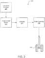
- the brake systems 200 of aircraft 10 may include a user input interface 205, a displacement sensor 210, a controller 220, a brake assembly 230, and a wheel 213.
- the brake system 200 generally controls the braking force and/or torque applied at each wheel 213, according to various embodiments.
- the brake system 200 may be, for example, a primary brake system, an emergency brake system, a park brake system, etc.
- the brake assembly 230 may include a non-rotatable wheel support (for rotatably supporting a wheel) and a brake disk stack.
- the brake disk stack may have alternating rotor and stator disks mounted with respect to the wheel support and wheel for relative axial movement. Each rotor disk may be coupled to the wheel for rotation therewith, and each stator disk may be coupled to the wheel support against rotation.
- a back plate may be located at the rear end of the disk pack and a brake head may be located at the front end.
- the brake head may house one or more actuator rams that extend to compress the brake disk stack against the back plate, or the brake disk stack may be compressed by other means. Torque is taken out by the stator disks through a static torque tube or the like.
- the actuator rams may be electrically operated actuator rams or hydraulically operated actuator rams, although some brakes may use pneumatically operated actuator rams.
- the brake assembly 230 may employ fluid powered (hydraulic or pneumatic power) actuator rams or electromechanical actuator arms.
- the brake assembly 230 may be a hydraulic assembly and thus may be coupled to a power source via a brake servo valve (BSV) and a shutoff valve (SOV).
- BSV brake servo valve
- SOV shutoff valve
- the SOV may effectively function as a shutoff valve such that in response to the valve being in the first position (e.g., an armed position), fluid pressure is permitted to pass through the valve while in response to the valve being in a second position (e.g., a disarmed position), fluid pressure is restricted or prevented from passing through the valve.
- the brake assembly 230 is electric and includes an electromechanical actuator controller (EMAC) to control braking.
- EMC electromechanical actuator controller
- the brake system 200 receives user input via the user input interface 205, as detected by the displacement sensor 210, and the controller 220 controls the amount of fluid pressure or electromechanical force provided to the actuator ram, thus
- the controller 220 may be configured to receive a signal from the displacement sensor 210, as described in greater detail below with reference to FIGS. 3A-3D , and translate the signals into a command to be sent to the brake assembly 230.
- the controller 220 may be integrated into computer systems onboard aircraft 10 such as, for example, a brake control unit (BCU), a full authority digital engine control (FADEC), an engine-indicating and crew-alerting system (EICAS), and/or the like.
- the controller 220 may also be a standalone computer system separate from aircraft 10 and in electronic communication with aircraft 10, as described in further detail herein.
- the controller 220 may include one or more processors and/or one or more tangible, non-transitory memories and be capable of implementing logic.
- Each processor can be a general purpose processor, a digital signal processor (DSP), an application specific integrated circuit (ASIC), a field programmable gate array (FPGA) or other programmable logic device, discrete gate or transistor logic, discrete hardware components, or any combination thereof.
- DSP digital signal processor
- ASIC application specific integrated circuit
- FPGA field programmable gate array
- the processor of the controller 220 may be configured to implement various logical operations in response to execution of instructions, for example, instructions stored on the non-transitory memory (e.g., tangible, computer-readable medium).
- the term "non-transitory” is to be understood to remove only propagating transitory signals per se from the claim scope and does not relinquish rights to all standard computer-readable media that are not only propagating transitory signals per se.
- the brake system 200 includes one or more user input interfaces 205 for receiving actuation/input from a user.
- the brake system 200 may be a primary brake system and the user input interface 205 may be a primary brake pedal located in a cockpit of the aircraft 10. The pilot/copilot may push the brake pedal in order to request the application of braking force.
- the user input interface 205 may be an emergency brake handle, or other movable mechanical component. The user input interface 205 may be integrated within a cockpit of the aircraft, or may be separate from the cockpit.
- the displacement sensor 210 detects the displacement of the user input interface 205 from a neutral or "zero" position and communicates the detected signal to the controller 220.
- the displacement sensor 210 may include any suitable sensor, such as, for example, a linear variable differential transformer (LVDT), a rotary variable differential transformer (RVDT), a potentiometer, a magnetic encoder, and/or the like.
- the displacement sensor 210 may transmit the a signal as a variable brake signal representative of the displacement of the user input interface 205, which may be a percentage of displacement from a reference position to a maximum reference position.
- the displacement sensor is a dual-mode potentiometer 310. While numerous details are included above pertaining to aircraft systems and/or brake systems, use of the dual-mode potentiometer 310 is not limited to aircraft and/or braking implementations. Thus, the dual-mode potentiometer 310 disclosed herein may be employed in other applications in which displacement measurements are warranted.
- the dual-mode potentiometer 310 may be especially beneficial in aircraft braking applications because of aircraft operating conditions. That is, as mentioned above, a conventional displacement sensor employed in a brake system of an aircraft may be damaged as operational vibrations cause contacting surfaces of conventional displacement sensors to wear against each other.
- the dual-mode potentiometer 310 of the present disclosure includes a resistive element 312 and a wiper element 314, according to various embodiments.
- the resistive element 312 may include two electrical terminals 311, 313 on opposing ends of the resistive element 312.
- the dual-mode potentiometer 310 may operate in either a parked mode or in a sensing mode, as described in greater detail below.
- the wiper element 314 in the sensing mode is in sliding electrical contact with the resistive element 312.
- the electric potential e.g., voltage
- the relative position of the wiper element 314 which is indicative of the position of the user input interface 205 (e.g., brake pedal), may be utilized by the controller 220 to command application of a braking force by the brake assembly 230.
- the wiper element 314 in the parked mode the wiper element 314 is separated from the resistive element 312 so that a gap 318 is defined between the two elements 312, 314.
- the wiper element 314 may include a wiper head 315 and the gap 318 may be defined between the wiper head 315 and the resistive element 312.
- the gap 318 prevents the elements 312, 314 from wearing against each other.
- the dual-mode potentiometer 310 does not detect the relative position of the wiper element 314 along the length of the resistive element 312.
- the wiper element 314 is completely decoupled from the resistive element 312 in the parked mode so that vibrations in the resistive element 312 are not conveyed to the wiper element 314.
- the dual-mode potentiometer 310 can operate in the sensing mode and the position of the wiper element 314 relative to the resistive element 312 can be determined based on the measured electrical voltage. If displacement measurements of the user input interface 205 are not warranted (e.g., during flight or during other, non-braking conditions), the dual-mode potentiometer 310 can operate in the parked mode to prevent wear to surfaces that would otherwise be in contact with each other.
- the dual-mode potentiometer 310 may include an electrically nonconductive wiper lift element 316.
- the electrically nonconductive wiper lift element 316 may be disposed between the wiper element 314 and the resistive element 312 in the parked mode to maintain the gap 318 between the two elements 312, 314.
- the electrically nonconductive wiper lift element 316 has an angled surface 317 along which the wiper element 314 may slide as it transitions between the parked mode and the sensing mode.
- the electrically nonconductive wiper lift element 316 may engage a body portion or an arm portion (e.g., not the wiper head 315) of the wiper element 314 to separate the wiper head 315 from the resistive element 312.
- the electrically nonconductive wiper lift element 316 may have a geometry and shape that are different from the schematic depiction in FIGs. 3C and 3D . That is, the dual-mode potentiometer 310 of the present disclosure may include other components, mechanisms, or elements that facilitate switching between the parked mode and the sensing mode.
- a user input interface 205 such as a brake pedal or a brake handle, can be coupled to one of either the resistive element 312 or the wiper element 314.
- displacement of the user input interface 205 causes a corresponding displacement of either the resistive element 312 or the wiper element 314. If the dual-mode potentiometer is in the sensing mode, this relative displacement can be measured by the potentiometer and transmitted to the controller 220.
- actuation of the user input interface 205 may be determinative of whether the dual-mode potentiometer 310 is in the parked mode or the sensing mode. Said differently, which mode the dual-mode potentiometer 310 operates in may be dependent on the existence of and/or magnitude of actuation via the user input interface 205. That is, the dual-mode potentiometer 310 may be configured to toggle between the parked mode and the sensing mode in response to actuation of the user input.
- the dual-mode potentiometer 310 may normally (e.g., by default) operate in the parked mode until a certain threshold of actuation via the user input interface 205 is received. For example, if the pilot or copilot does not actuate the user input interface 205 (e.g., does not push the brake pedal) or if the user input interface 205 is only actuated within (e.g., does not exceed) a "deadband" displacement threshold (i.e., an interval, domain, or range of actuation from a zero position), the dual-mode potentiometer 310 may remain in the parked mode, thereby preventing damage to the elements 312, 314 of the dual-mode potentiometer 310 by maintaining a gap 318 between the two elements 312, 314.
- the "deadband" threshold may be specifically and purposefully designed into the structure of the user input interface 205.
- the resistive element 412 of the dual-mode potentiometer 410 may have a notch 419 (e.g., channel, groove, depression, etc.) formed on the outer surface of the resistive element 412 that facilitates the gap 418 defined between the wiper element 414 (e.g., the wiper head 415) and the resistive element 412 in the parked mode.
- the notch 419 may have various shapes or geometries.
- relative movement between the resistive element 412 and the wiper element 414 can cause the wiper element 414 to close the gap 418 such that the wiper element 414 is in electrical contact with the resistive element 412 in the sensing mode ( FIG.
- the wiper element 414 translates linearly and the resistive element 412 is stationary.
- the dual-mode potentiometer 410 can switch between the parked mode and the sensing mode via linear translation of the wiper element 414 to respectively switch whether the wiper head 415 is disposed over the notch 419 or whether the wiper head 415 is in electrical contact with the resistive element 412.
- a method 590 of controlling the brake system 200 is provided.
- the controller 220 may transmit a null command to the brake assembly 230 at step 592 of the method 590. That is, in response to "no actuation" of the user input interface 205 or in response to actuation of the user input interface 205 within a deadband threshold, no braking command may be sent by the controller 220 to the brake assembly 230. In various embodiments, the controller 220 may send a command that indicates "no braking" to the brake assembly 230.
- the dual-mode potentiometer 310 changes to the sensing mode to measure electric potential (i.e., voltage) to detect the extent of the displacement of the user input interface 205. That is, in response to actuation of the user input interface 205 or in response to actuation that exceeds the deadband threshold, a braking command may be transmitted, by the controller 220 to the brake assembly 230 at step 594 of the method 590, in accordance with various embodiments and with reference to FIG. 5 .
- the braking command may correspond to the measured displacement of the user input interface 205.
- the resistive element 312 of the dual-mode potentiometer 310 may be made from various materials, include metal, ceramic, and/or conductive plastic, among others.
- the components of the dual-mode potentiometer 310, such as the resistive element 312 may be made from less expensive materials than would otherwise be possible with conventional displacement sensors because of the wear-preventing ability of the parked mode.
- any reference to attached, fixed, connected, coupled or the like may include permanent (e.g., integral), removable, temporary, partial, full, and/or any other possible attachment option.
- permanent e.g., integral
- removable temporary, partial, full
- any other possible attachment option e.g., permanent, temporary, partial, full, and/or any other possible attachment option.
- Different cross-hatching is used throughout the figures to denote different parts but not necessarily to denote the same or different materials.
- any of the method or process descriptions may be executed in any order and are not necessarily limited to the order presented.
- any reference to singular includes plural embodiments, and any reference to more than one component or step may include a singular embodiment or step.
- Elements and steps in the figures are illustrated for simplicity and clarity and have not necessarily been rendered according to any particular sequence. For example, steps that may be performed concurrently or in different order are illustrated in the figures to help to improve understanding of embodiments of the present disclosure.
- Any reference to attached, fixed, connected or the like may include permanent, removable, temporary, partial, full and/or any other possible attachment option. Additionally, any reference to without contact (or similar phrases) may also include reduced contact or minimal contact. Surface shading lines may be used throughout the figures to denote different parts or areas but not necessarily to denote the same or different materials. In some cases, reference coordinates may be specific to each figure.
- references to "one embodiment”, “an embodiment”, “various embodiments”, etc. indicate that the embodiment described may include a particular feature, structure, or characteristic, but every embodiment may not necessarily include the particular feature, structure, or characteristic. Moreover, such phrases are not necessarily referring to the same embodiment. Further, when a particular feature, structure, or characteristic is described in connection with an embodiment, it is submitted that it is within the knowledge of one skilled in the art to affect such feature, structure, or characteristic in connection with other embodiments whether or not explicitly described. After reading the description, it will be apparent to one skilled in the relevant art(s) how to implement the disclosure in alternative embodiments.
Landscapes
- Engineering & Computer Science (AREA)
- Mechanical Engineering (AREA)
- Transportation (AREA)
- Aviation & Aerospace Engineering (AREA)
- Physics & Mathematics (AREA)
- General Physics & Mathematics (AREA)
- Fluid Mechanics (AREA)
- Microelectronics & Electronic Packaging (AREA)
- Braking Elements And Transmission Devices (AREA)
- Mechanical Control Devices (AREA)
- Regulating Braking Force (AREA)
Abstract
Description
- The present disclosure relates to displacement sensors, and more specifically, to potentiometers.
- Displacement sensors are used in different applications to measure the relative position of components. For example, displacement sensors can be used in the aircraft industry to measure displacement of the brake pedal. The measured displacement can then be converted into a braking command to be conveyed to a brake assembly.
- There are many different types of displacement sensors. Potentiometers are one type of displacement sensors that can be coupled to a user input, such as a brake pedal, and utilized to detect the extent/amount/magnitude of user input. Potentiometers are multiple terminal resistors that can be used to measure electric voltage. A potentiometer can be calibrated so that a measured electric voltage can be correlated with a relative position of a movable electric contact of the potentiometer. However, due to conditions that are often present while operating an aircraft, potentiometers and other displacement sensors may fail due to excessive wear caused by vibrations propagating through contacting surfaces of the displacement sensors.
- In various embodiments, the present disclosure provides a displacement sensor that includes a resistive element and a wiper element. The wiper element may be separated from the resistive element in response to the displacement sensor being in a parked mode and the wiper element may be in sliding electrical contact with the resistive element in response to the displacement sensor being in a sensing mode. In various embodiments, a user input interface is coupled to at least one of the resistive element and the wiper element, wherein whether the displacement sensor is in the parked mode or the sensing mode is dependent on actuation of the user input interface.
- According to various embodiments, the displacement sensor is configured to toggle between the parked mode and the sensing mode in response to actuation of the user input interface. The displacement sensor may default to the parked mode in response to no actuation of the user input interface and the displacement sensor may change to the sensing mode in response to a threshold actuation of the user input interface. The threshold actuation may be a deadband displacement of the user input interface. The user input interface may be a brake pedal or a brake handle, among others.
- The displacement sensor may further include a controller such that, in response to the displacement sensor being in the sensing mode, the controller of the displacement sensor transmits a signal corresponding to a position of the wiper element relative to the resistive element. In various embodiments, the displacement sensor further includes an electrically nonconductive wiper lift element that is disposed between the wiper element and the resistive element in the parked mode. The electrically nonconductive wiper lift element may have an angled surface along which the wiper element slides (e.g., as the wiper element transitions between the parked mode and the sensing mode). In various embodiments, the resistive element is made from a conductive plastic. In various embodiments, the resistive element is made from a ceramic material.
- Also disclosed herein, according to various embodiments, is a brake system that includes a displacement sensor and a brake pedal coupled to the displacement sensor. The displacement sensor may include a resistive element and a wiper element. The wiper element may be separated from the resistive element in response to the displacement sensor being in a parked mode and the wiper element may be in sliding electrical contact with the resistive element in response to the displacement sensor being in a sensing mode. In various embodiments, whether the displacement sensor is in the parked mode or the sensing mode is dependent on actuation of the brake pedal. The displacement sensor may further include an electrically nonconductive wiper lift element disposed between the wiper element and the resistive element in the parked mode.
- Also disclosed herein, according to various embodiments, is a brake system of an aircraft. The brake system includes, according to various embodiments, a user input interface, a displacement sensor, a brake assembly, a controller, and a tangible non-transitory memory. The displacement sensor may be coupled to the user input interface and configured to detect displacement of the user input interface. The brake assembly may be coupled to a wheel of the aircraft. The controller may include a processor and the controller may be in electrical communication with the displacement sensor and the brake assembly. The tangible, non-transitory memory may be configured to communicate with the processor. The tangible, non-transitory memory, according to various embodiments, has instructions stored thereon that, in response to execution by the processor, cause the brake system to perform various operations. The various operations include, according to various embodiments, transmitting, by the controller, a null command to the brake assembly and transmitting, by the controller, a braking command to the brake assembly. Transmitting the null command to the brake assembly may be in response to actuation of the user input interface within a deadband threshold and transmitting the braking command to the brake assembly may be in response to actuation of the user input interface exceeding the deadband threshold.
- In various embodiments, the displacement sensor includes a resistive element and a wiper element. The wiper element may be separated from the resistive element in response to actuation of the user input interface within the deadband threshold and the wiper element may be in sliding electrical contact with the resistive element in response to actuation of the user input interface exceeding the deadband threshold. The braking command may correspond to a position of the wiper element relative to the resistive element. The user input interface may be a brake pedal or a brake handle, among other mechanisms.
- The forgoing features and elements may be combined in various combinations without exclusivity, unless expressly indicated herein otherwise. These features and elements as well as the operation of the disclosed embodiments will become more apparent in light of the following description and accompanying drawings.
- The subject matter of the present disclosure is particularly pointed out and distinctly claimed in the concluding portion of the specification. A more complete understanding of the present disclosure, however, may best be obtained by referring to the detailed description and claims when considered in connection with the following illustrative figures. In the following figures, like reference numbers refer to similar elements and steps throughout the figures.
-
FIG. 1 illustrates an exemplary aircraft having a wheel and brake system, in accordance with various embodiments; -
FIG. 2 illustrates a schematic of a brake system, in accordance with various embodiments; -
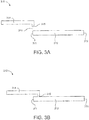
FIG. 3A illustrates a schematic of a displacement sensor in a parked mode, in accordance with various embodiments; -
FIG. 3B illustrates a schematic of a displacement sensor in a sensing mode, in accordance with various embodiments; -
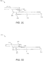
FIG. 3C illustrates a schematic of a displacement sensor in a parked mode, in accordance with various embodiments; -
FIG. 3D illustrates a schematic of a displacement sensor in a sensing mode, in accordance with various embodiments; -
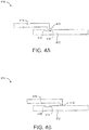
FIG. 4A illustrates a schematic of a displacement sensor in a parked mode, in accordance with various embodiments; -
FIG. 4B illustrates a schematic of a displacement sensor in a sensing mode, in accordance with various embodiments; and -
FIG. 5 is a schematic flow chart diagram of a method of controlling a brake system, in accordance with various embodiments. - The detailed description of exemplary embodiments herein makes reference to the accompanying drawings, which show exemplary embodiments by way of illustration. While these exemplary embodiments are described in sufficient detail to enable those skilled in the art to practice the disclosure, it should be understood that other embodiments may be realized and that logical changes and adaptations in design and construction may be made in accordance with this disclosure and the teachings herein without departing from the scope of the invention as defined by the claims. Thus, the detailed description herein is presented for purposes of illustration only and not of limitation.
- Referring now to
FIG. 1 , in accordance with various embodiments, anaircraft 10 may include landing gear such asmain landing gear 12,main landing gear 14 andnose landing gear 16.Main landing gear 12,main landing gear 14, andnose landing gear 16 may generally supportaircraft 10 whenaircraft 10 is not flying, allowingaircraft 10 to taxi, take off and land without damage.Main landing gear 12 may includewheel 13A andwheel 13B coupled by anaxle 20.Main landing gear 14 may includewheel 15A andwheel 15B coupled by anaxle 22.Nose landing gear 16 may includenose wheel 17A andnose wheel 17B coupled by anaxle 24. In various embodiments,aircraft 10 may comprise any number of landing gears and each landing gear may comprise any number of wheels.Main landing gear 12,main landing gear 14, andnose landing gear 16 may each be retracted for flight. - In various embodiments, and with reference to
FIG. 2 ,aircraft 10 may also include one ormore brake systems 200. Thebrake systems 200 ofaircraft 10 may include a user input interface 205, adisplacement sensor 210, acontroller 220, abrake assembly 230, and awheel 213. As described in greater detail below, thebrake system 200 generally controls the braking force and/or torque applied at eachwheel 213, according to various embodiments. Thebrake system 200 may be, for example, a primary brake system, an emergency brake system, a park brake system, etc. - The
brake assembly 230 may include a non-rotatable wheel support (for rotatably supporting a wheel) and a brake disk stack. The brake disk stack may have alternating rotor and stator disks mounted with respect to the wheel support and wheel for relative axial movement. Each rotor disk may be coupled to the wheel for rotation therewith, and each stator disk may be coupled to the wheel support against rotation. A back plate may be located at the rear end of the disk pack and a brake head may be located at the front end. The brake head may house one or more actuator rams that extend to compress the brake disk stack against the back plate, or the brake disk stack may be compressed by other means. Torque is taken out by the stator disks through a static torque tube or the like. The actuator rams may be electrically operated actuator rams or hydraulically operated actuator rams, although some brakes may use pneumatically operated actuator rams. - The
brake assembly 230 may employ fluid powered (hydraulic or pneumatic power) actuator rams or electromechanical actuator arms. For example, thebrake assembly 230 may be a hydraulic assembly and thus may be coupled to a power source via a brake servo valve (BSV) and a shutoff valve (SOV). The SOV may effectively function as a shutoff valve such that in response to the valve being in the first position (e.g., an armed position), fluid pressure is permitted to pass through the valve while in response to the valve being in a second position (e.g., a disarmed position), fluid pressure is restricted or prevented from passing through the valve. In various embodiments, thebrake assembly 230 is electric and includes an electromechanical actuator controller (EMAC) to control braking. Generally, thebrake system 200 receives user input via the user input interface 205, as detected by thedisplacement sensor 210, and thecontroller 220 controls the amount of fluid pressure or electromechanical force provided to the actuator ram, thus applying a braking force to thewheel 213. - The
controller 220 may be configured to receive a signal from thedisplacement sensor 210, as described in greater detail below with reference toFIGS. 3A-3D , and translate the signals into a command to be sent to thebrake assembly 230. Thecontroller 220 may be integrated into computer systems onboardaircraft 10 such as, for example, a brake control unit (BCU), a full authority digital engine control (FADEC), an engine-indicating and crew-alerting system (EICAS), and/or the like. Thecontroller 220 may also be a standalone computer system separate fromaircraft 10 and in electronic communication withaircraft 10, as described in further detail herein. Thecontroller 220 may include one or more processors and/or one or more tangible, non-transitory memories and be capable of implementing logic. Each processor can be a general purpose processor, a digital signal processor (DSP), an application specific integrated circuit (ASIC), a field programmable gate array (FPGA) or other programmable logic device, discrete gate or transistor logic, discrete hardware components, or any combination thereof. - In various embodiments, the processor of the
controller 220 may be configured to implement various logical operations in response to execution of instructions, for example, instructions stored on the non-transitory memory (e.g., tangible, computer-readable medium). As used herein, the term "non-transitory" is to be understood to remove only propagating transitory signals per se from the claim scope and does not relinquish rights to all standard computer-readable media that are not only propagating transitory signals per se. - In various embodiments, the
brake system 200 includes one or more user input interfaces 205 for receiving actuation/input from a user. For example, thebrake system 200 may be a primary brake system and the user input interface 205 may be a primary brake pedal located in a cockpit of theaircraft 10. The pilot/copilot may push the brake pedal in order to request the application of braking force. In various embodiments, the user input interface 205 may be an emergency brake handle, or other movable mechanical component. The user input interface 205 may be integrated within a cockpit of the aircraft, or may be separate from the cockpit. - The
displacement sensor 210, according to various embodiments, detects the displacement of the user input interface 205 from a neutral or "zero" position and communicates the detected signal to thecontroller 220. Thedisplacement sensor 210 may include any suitable sensor, such as, for example, a linear variable differential transformer (LVDT), a rotary variable differential transformer (RVDT), a potentiometer, a magnetic encoder, and/or the like. Thedisplacement sensor 210 may transmit the a signal as a variable brake signal representative of the displacement of the user input interface 205, which may be a percentage of displacement from a reference position to a maximum reference position. - In various embodiments, and with reference to
FIGs. 3A-3C , the displacement sensor is a dual-mode potentiometer 310. While numerous details are included above pertaining to aircraft systems and/or brake systems, use of the dual-mode potentiometer 310 is not limited to aircraft and/or braking implementations. Thus, the dual-mode potentiometer 310 disclosed herein may be employed in other applications in which displacement measurements are warranted. - The dual-
mode potentiometer 310, according to various embodiments, may be especially beneficial in aircraft braking applications because of aircraft operating conditions. That is, as mentioned above, a conventional displacement sensor employed in a brake system of an aircraft may be damaged as operational vibrations cause contacting surfaces of conventional displacement sensors to wear against each other. - The dual-
mode potentiometer 310 of the present disclosure includes aresistive element 312 and awiper element 314, according to various embodiments. Theresistive element 312 may include twoelectrical terminals resistive element 312. The dual-mode potentiometer 310 may operate in either a parked mode or in a sensing mode, as described in greater detail below. - In various embodiments, and with reference to
FIGs. 3B and3D , in the sensing mode thewiper element 314 is in sliding electrical contact with theresistive element 312. In the sensing mode, the electric potential (e.g., voltage) between either terminal 311, 313 of theresistive element 312 and thewiper element 314 can be measured in order to determine the relative position of thewiper element 314 relative to theresistive element 312. The relative position of thewiper element 314, which is indicative of the position of the user input interface 205 (e.g., brake pedal), may be utilized by thecontroller 220 to command application of a braking force by thebrake assembly 230. - In various embodiments, and with reference to
FIGs. 3A and3C , in the parked mode thewiper element 314 is separated from theresistive element 312 so that agap 318 is defined between the twoelements wiper element 314 may include awiper head 315 and thegap 318 may be defined between thewiper head 315 and theresistive element 312. Thegap 318 prevents theelements gap 318 opens the sensing circuit, in the parked mode the dual-mode potentiometer 310 does not detect the relative position of thewiper element 314 along the length of theresistive element 312. In various embodiments, thewiper element 314 is completely decoupled from theresistive element 312 in the parked mode so that vibrations in theresistive element 312 are not conveyed to thewiper element 314. - If displacement measurements of the user input interface 205, with reference to
FIG. 2 , are warranted, the dual-mode potentiometer 310 can operate in the sensing mode and the position of thewiper element 314 relative to theresistive element 312 can be determined based on the measured electrical voltage. If displacement measurements of the user input interface 205 are not warranted (e.g., during flight or during other, non-braking conditions), the dual-mode potentiometer 310 can operate in the parked mode to prevent wear to surfaces that would otherwise be in contact with each other. - In various embodiments, and with reference to
FIGs. 3C and 3D , the dual-mode potentiometer 310 may include an electrically nonconductivewiper lift element 316. The electrically nonconductivewiper lift element 316 may be disposed between thewiper element 314 and theresistive element 312 in the parked mode to maintain thegap 318 between the twoelements wiper lift element 316 has anangled surface 317 along which thewiper element 314 may slide as it transitions between the parked mode and the sensing mode. In various embodiments, the electrically nonconductivewiper lift element 316 may engage a body portion or an arm portion (e.g., not the wiper head 315) of thewiper element 314 to separate thewiper head 315 from theresistive element 312. In various embodiments, the electrically nonconductivewiper lift element 316 may have a geometry and shape that are different from the schematic depiction inFIGs. 3C and 3D . That is, the dual-mode potentiometer 310 of the present disclosure may include other components, mechanisms, or elements that facilitate switching between the parked mode and the sensing mode. - In various embodiments, as mentioned above, a user input interface 205, such as a brake pedal or a brake handle, can be coupled to one of either the
resistive element 312 or thewiper element 314. In such embodiments, displacement of the user input interface 205 causes a corresponding displacement of either theresistive element 312 or thewiper element 314. If the dual-mode potentiometer is in the sensing mode, this relative displacement can be measured by the potentiometer and transmitted to thecontroller 220. - In various embodiments, actuation of the user input interface 205 may be determinative of whether the dual-
mode potentiometer 310 is in the parked mode or the sensing mode. Said differently, which mode the dual-mode potentiometer 310 operates in may be dependent on the existence of and/or magnitude of actuation via the user input interface 205. That is, the dual-mode potentiometer 310 may be configured to toggle between the parked mode and the sensing mode in response to actuation of the user input. - In various embodiments, the dual-
mode potentiometer 310 may normally (e.g., by default) operate in the parked mode until a certain threshold of actuation via the user input interface 205 is received. For example, if the pilot or copilot does not actuate the user input interface 205 (e.g., does not push the brake pedal) or if the user input interface 205 is only actuated within (e.g., does not exceed) a "deadband" displacement threshold (i.e., an interval, domain, or range of actuation from a zero position), the dual-mode potentiometer 310 may remain in the parked mode, thereby preventing damage to theelements mode potentiometer 310 by maintaining agap 318 between the twoelements - In various embodiments, and with reference to
FIGs. 4A and 4B , theresistive element 412 of the dual-mode potentiometer 410 may have a notch 419 (e.g., channel, groove, depression, etc.) formed on the outer surface of theresistive element 412 that facilitates thegap 418 defined between the wiper element 414 (e.g., the wiper head 415) and theresistive element 412 in the parked mode. Thenotch 419 may have various shapes or geometries. In various embodiments, relative movement between theresistive element 412 and thewiper element 414, can cause thewiper element 414 to close thegap 418 such that thewiper element 414 is in electrical contact with theresistive element 412 in the sensing mode (FIG. 4B ). For example, in various embodiments thewiper element 414 translates linearly and theresistive element 412 is stationary. The dual-mode potentiometer 410 can switch between the parked mode and the sensing mode via linear translation of thewiper element 414 to respectively switch whether thewiper head 415 is disposed over thenotch 419 or whether thewiper head 415 is in electrical contact with theresistive element 412. - In various embodiments, and with reference to
FIG. 5 , amethod 590 of controlling thebrake system 200 is provided. In various embodiments, in the parked mode, thecontroller 220 may transmit a null command to thebrake assembly 230 atstep 592 of themethod 590. That is, in response to "no actuation" of the user input interface 205 or in response to actuation of the user input interface 205 within a deadband threshold, no braking command may be sent by thecontroller 220 to thebrake assembly 230. In various embodiments, thecontroller 220 may send a command that indicates "no braking" to thebrake assembly 230. In response the pilot or copilot actuating the user input interface 205 (e.g., pushing on the brake pedal) or actuating the user input interface 205 beyond the deadband displacement threshold, the dual-mode potentiometer 310 changes to the sensing mode to measure electric potential (i.e., voltage) to detect the extent of the displacement of the user input interface 205. That is, in response to actuation of the user input interface 205 or in response to actuation that exceeds the deadband threshold, a braking command may be transmitted, by thecontroller 220 to thebrake assembly 230 atstep 594 of themethod 590, in accordance with various embodiments and with reference toFIG. 5 . The braking command may correspond to the measured displacement of the user input interface 205. - In various embodiments, the
resistive element 312 of the dual-mode potentiometer 310 may be made from various materials, include metal, ceramic, and/or conductive plastic, among others. In various embodiments, the components of the dual-mode potentiometer 310, such as theresistive element 312, may be made from less expensive materials than would otherwise be possible with conventional displacement sensors because of the wear-preventing ability of the parked mode. - Benefits, other advantages, and solutions to problems have been described herein with regard to specific embodiments. Furthermore, the connecting lines shown in the various figures contained herein are intended to represent exemplary functional relationships and/or physical couplings between the various elements. It should be noted that many alternative or additional functional relationships or physical connections may be present in a practical system. However, the benefits, advantages, solutions to problems, and any elements that may cause any benefit, advantage, or solution to occur or become more pronounced are not to be construed as critical, required, or essential features or elements of the disclosure.
- The scope of the disclosure is accordingly to be limited by nothing other than the appended claims, in which reference to an element in the singular is not intended to mean "one and only one" unless explicitly so stated, but rather "one or more." It is to be understood that unless specifically stated otherwise, references to "a," "an," and/or "the" may include one or more than one and that reference to an item in the singular may also include the item in the plural. All ranges and ratio limits disclosed herein may be combined.
- Moreover, where a phrase similar to "at least one of A, B, and C" is used in the claims, it is intended that the phrase be interpreted to mean that A alone may be present in an embodiment, B alone may be present in an embodiment, C alone may be present in an embodiment, or that any combination of the elements A, B and C may be present in a single embodiment; for example, A and B, A and C, B and C, or A and B and C.
- Also, any reference to attached, fixed, connected, coupled or the like may include permanent (e.g., integral), removable, temporary, partial, full, and/or any other possible attachment option. Different cross-hatching is used throughout the figures to denote different parts but not necessarily to denote the same or different materials.
- The steps recited in any of the method or process descriptions may be executed in any order and are not necessarily limited to the order presented. Furthermore, any reference to singular includes plural embodiments, and any reference to more than one component or step may include a singular embodiment or step. Elements and steps in the figures are illustrated for simplicity and clarity and have not necessarily been rendered according to any particular sequence. For example, steps that may be performed concurrently or in different order are illustrated in the figures to help to improve understanding of embodiments of the present disclosure.
- Any reference to attached, fixed, connected or the like may include permanent, removable, temporary, partial, full and/or any other possible attachment option. Additionally, any reference to without contact (or similar phrases) may also include reduced contact or minimal contact. Surface shading lines may be used throughout the figures to denote different parts or areas but not necessarily to denote the same or different materials. In some cases, reference coordinates may be specific to each figure.
- Systems, methods and apparatus are provided herein. In the detailed description herein, references to "one embodiment", "an embodiment", "various embodiments", etc., indicate that the embodiment described may include a particular feature, structure, or characteristic, but every embodiment may not necessarily include the particular feature, structure, or characteristic. Moreover, such phrases are not necessarily referring to the same embodiment. Further, when a particular feature, structure, or characteristic is described in connection with an embodiment, it is submitted that it is within the knowledge of one skilled in the art to affect such feature, structure, or characteristic in connection with other embodiments whether or not explicitly described. After reading the description, it will be apparent to one skilled in the relevant art(s) how to implement the disclosure in alternative embodiments.
Claims (15)
- A displacement sensor comprising:a resistive element (312); anda wiper element (314);wherein the wiper element is separated from the resistive element in response to the displacement sensor being in a parked mode and wherein the wiper element is in sliding electrical contact with the resistive element in response to the displacement sensor being in a sensing mode.
- The displacement sensor of claim 1, wherein whether the displacement sensor is in the parked mode or the sensing mode is dependent on actuation of a user input interface coupled to at least one of the resistive element and the wiper element.
- The displacement sensor of claim 2, wherein the displacement sensor is configured to toggle between the parked mode and the sensing mode in response to actuation of the user input interface, or wherein the displacement sensor defaults to the parked mode in response to no actuation of the user input interface.
- The displacement sensor of claim 3, wherein the displacement sensor changes to the sensing mode in response to a threshold actuation of the user input interface.
- The displacement sensor of claim 4, wherein the threshold actuation comprises a deadband displacement of the user input interface.
- The displacement sensor of claim 2, wherein the user input interface is a brake pedal, or wherein the user input interface is a brake handle.
- The displacement sensor of any preceding claim, wherein the resistive element comprises a notch and the wiper element comprises a wiper head, wherein the wiper head is disposed in the notch in the parked mode such that the wiper head is separated from the resistive element.
- The displacement sensor of any preceding claim, further comprising an electrically nonconductive wiper lift element, wherein the electrically nonconductive wiper lift element is disposed between the wiper element and the resistive element in the parked mode.
- The displacement sensor of claim 8, wherein the electrically nonconductive wiper lift element has an angled surface along which the wiper element slides.
- The displacement sensor of any preceding claim, wherein the resistive element is made from conductive plastic, or wherein the resistive element is made from a ceramic material.
- A brake system comprising:a displacement sensor (210) as claimed in any preceding claim; anda user input interface (205) coupled to the displacement sensor, wherein whether the displacement sensor is in the parked mode or the sensing mode is dependent on actuation of the user input interface.
- The brake system of claim 11, further comprising:a brake assembly (230) coupled to a wheel (213) of an aircraft (10);a controller (220) having a processor, wherein the controller is in electrical communication with the displacement sensor and the brake assembly; anda tangible, non-transitory memory configured to communicate with the processor, the tangible, non-transitory memory having instructions stored thereon that, in response to execution by the processor, cause the brake system to perform operations comprising:in response to actuation of the user input interface within a deadband threshold, transmitting, by the controller, a null command to the brake assembly; andin response to actuation of the user input interface exceeding the deadband threshold, transmitting, by the controller a braking command to the brake assembly.
- The brake system of claim 12, wherein:the wiper element is separated from the resistive element in response to actuation of the user input interface within the deadband threshold; andthe wiper element is in sliding electrical contact with the resistive element in response to actuation of the user input interface exceeding the deadband threshold.
- The brake system of claim 12, wherein the braking command corresponds to a position of the wiper element relative to the resistive element.
- A method of controlling a brake system, the method comprising:in response to actuation of a user input interface within a deadband threshold, transmitting, by the controller, a null command to a brake assembly of the brake system; andin response to actuation of the user input interface exceeding the deadband threshold, transmitting, by the controller a braking command to the brake assembly.
Applications Claiming Priority (1)
| Application Number | Priority Date | Filing Date | Title |
|---|---|---|---|
| US15/426,254 US10006785B1 (en) | 2017-02-07 | 2017-02-07 | Displacement sensor |
Publications (2)
| Publication Number | Publication Date |
|---|---|
| EP3358578A1 true EP3358578A1 (en) | 2018-08-08 |
| EP3358578B1 EP3358578B1 (en) | 2019-12-18 |
Family
ID=61187216
Family Applications (1)
| Application Number | Title | Priority Date | Filing Date |
|---|---|---|---|
| EP18155608.5A Active EP3358578B1 (en) | 2017-02-07 | 2018-02-07 | Displacement sensor |
Country Status (2)
| Country | Link |
|---|---|
| US (2) | US10006785B1 (en) |
| EP (1) | EP3358578B1 (en) |
Families Citing this family (5)
| Publication number | Priority date | Publication date | Assignee | Title |
|---|---|---|---|---|
| US10006785B1 (en) * | 2017-02-07 | 2018-06-26 | Goodrich Corporation | Displacement sensor |
| US11557988B2 (en) * | 2020-01-28 | 2023-01-17 | Goodrich Corporation | Hybrid regeneration brake system |
| GB2605160B (en) * | 2021-03-24 | 2023-05-31 | Safran Landing Systems Uk Ltd | Aircraft landing gear torque link assembly |
| WO2024182118A1 (en) * | 2023-02-27 | 2024-09-06 | Gulfstream Aerospace Corporation | Actuation deadband compensation systems and methodologies |
| CN118479032B (en) * | 2024-06-06 | 2025-12-05 | 西安航空制动科技有限公司 | A control system and method for improving the safety of aircraft foot brakes |
Citations (5)
| Publication number | Priority date | Publication date | Assignee | Title |
|---|---|---|---|---|
| US3360756A (en) * | 1967-02-27 | 1967-12-26 | Gen Dynamics Corp | Potentiometer with lift-off wiper |
| CA882366A (en) * | 1971-09-28 | A. Vandenbroek Jan | Control for electric brake | |
| EP0096948A1 (en) * | 1982-06-11 | 1983-12-28 | Welwyn Electronics Limited | Potentiometer |
| US4623868A (en) * | 1984-01-10 | 1986-11-18 | Crystalate Electronics Limited | Variable electrical resistance device |
| US5803211A (en) * | 1996-01-31 | 1998-09-08 | Wilke; Richard | Motorized brake actuator, especially for rail vehicles |
Family Cites Families (6)
| Publication number | Priority date | Publication date | Assignee | Title |
|---|---|---|---|---|
| US6003640A (en) * | 1997-05-09 | 1999-12-21 | The B.F. Goodrich Company | Electronic braking system with brake wear measurement and running clearance adjustment |
| WO2008052051A2 (en) | 2006-10-24 | 2008-05-02 | Goodrich Corporation | Aircraft brake actuation measurement unit |
| WO2009089551A2 (en) | 2008-01-11 | 2009-07-16 | General Atomics | Braking system with linear actuator |
| GB2457376B (en) * | 2008-02-14 | 2011-12-07 | Goodrich Corp | Brake wear measurement system |
| CN102758962A (en) | 2011-04-28 | 2012-10-31 | 吴昊天 | Highly-precise non-contactable openness sensor for foot brake valve |
| US10006785B1 (en) * | 2017-02-07 | 2018-06-26 | Goodrich Corporation | Displacement sensor |
-
2017
- 2017-02-07 US US15/426,254 patent/US10006785B1/en active Active
-
2018
- 2018-02-07 EP EP18155608.5A patent/EP3358578B1/en active Active
- 2018-05-23 US US15/987,703 patent/US10422663B2/en active Active
Patent Citations (5)
| Publication number | Priority date | Publication date | Assignee | Title |
|---|---|---|---|---|
| CA882366A (en) * | 1971-09-28 | A. Vandenbroek Jan | Control for electric brake | |
| US3360756A (en) * | 1967-02-27 | 1967-12-26 | Gen Dynamics Corp | Potentiometer with lift-off wiper |
| EP0096948A1 (en) * | 1982-06-11 | 1983-12-28 | Welwyn Electronics Limited | Potentiometer |
| US4623868A (en) * | 1984-01-10 | 1986-11-18 | Crystalate Electronics Limited | Variable electrical resistance device |
| US5803211A (en) * | 1996-01-31 | 1998-09-08 | Wilke; Richard | Motorized brake actuator, especially for rail vehicles |
Also Published As
| Publication number | Publication date |
|---|---|
| US20180266850A1 (en) | 2018-09-20 |
| US10422663B2 (en) | 2019-09-24 |
| US10006785B1 (en) | 2018-06-26 |
| EP3358578B1 (en) | 2019-12-18 |
Similar Documents
| Publication | Publication Date | Title |
|---|---|---|
| EP3358578B1 (en) | Displacement sensor | |
| EP3748189B1 (en) | Retractable electronic wear pin | |
| EP2876011B1 (en) | System and method for maximum braking | |
| EP2871104B1 (en) | System for independent braking system enablement | |
| EP3333069B1 (en) | Systems and methods for aircraft emergency and park brakes | |
| US11639160B2 (en) | Electrical power connection in an emergency park brake system | |
| US10259569B2 (en) | Systems and methods for emergency aircraft brake operation | |
| US11597363B2 (en) | Brake position system | |
| EP1279854B1 (en) | Electronic aircraft braking system with brake wear measurement, running clearance adjustment and plural electric motor-actuator ram assemblies | |
| EP2567872A2 (en) | Systems and methods for emergency braking system | |
| EP2949524B1 (en) | Aircraft brake system testing methods | |
| EP3392140B1 (en) | Emergency park brake system | |
| EP3560779B1 (en) | Measurement of contact maintaining control valve current for a hydraulic actuator | |
| EP4183680A1 (en) | Feel adjustment braking systems and methods | |
| US9037371B2 (en) | Systems and methods for manual braking system | |
| US10493962B2 (en) | Brake position system | |
| EP4556326A1 (en) | Control for an electromechanical brake actuator |
Legal Events
| Date | Code | Title | Description |
|---|---|---|---|
| PUAI | Public reference made under article 153(3) epc to a published international application that has entered the european phase |
Free format text: ORIGINAL CODE: 0009012 |
|
| STAA | Information on the status of an ep patent application or granted ep patent |
Free format text: STATUS: THE APPLICATION HAS BEEN PUBLISHED |
|
| AK | Designated contracting states |
Kind code of ref document: A1 Designated state(s): AL AT BE BG CH CY CZ DE DK EE ES FI FR GB GR HR HU IE IS IT LI LT LU LV MC MK MT NL NO PL PT RO RS SE SI SK SM TR |
|
| AX | Request for extension of the european patent |
Extension state: BA ME |
|
| STAA | Information on the status of an ep patent application or granted ep patent |
Free format text: STATUS: REQUEST FOR EXAMINATION WAS MADE |
|
| 17P | Request for examination filed |
Effective date: 20190208 |
|
| RBV | Designated contracting states (corrected) |
Designated state(s): AL AT BE BG CH CY CZ DE DK EE ES FI FR GB GR HR HU IE IS IT LI LT LU LV MC MK MT NL NO PL PT RO RS SE SI SK SM TR |
|
| GRAP | Despatch of communication of intention to grant a patent |
Free format text: ORIGINAL CODE: EPIDOSNIGR1 |
|
| STAA | Information on the status of an ep patent application or granted ep patent |
Free format text: STATUS: GRANT OF PATENT IS INTENDED |
|
| INTG | Intention to grant announced |
Effective date: 20190708 |
|
| GRAS | Grant fee paid |
Free format text: ORIGINAL CODE: EPIDOSNIGR3 |
|
| GRAA | (expected) grant |
Free format text: ORIGINAL CODE: 0009210 |
|
| STAA | Information on the status of an ep patent application or granted ep patent |
Free format text: STATUS: THE PATENT HAS BEEN GRANTED |
|
| AK | Designated contracting states |
Kind code of ref document: B1 Designated state(s): AL AT BE BG CH CY CZ DE DK EE ES FI FR GB GR HR HU IE IS IT LI LT LU LV MC MK MT NL NO PL PT RO RS SE SI SK SM TR |
|
| REG | Reference to a national code |
Ref country code: CH Ref legal event code: EP |
|
| REG | Reference to a national code |
Ref country code: IE Ref legal event code: FG4D |
|
| REG | Reference to a national code |
Ref country code: DE Ref legal event code: R096 Ref document number: 602018001613 Country of ref document: DE |
|
| REG | Reference to a national code |
Ref country code: AT Ref legal event code: REF Ref document number: 1215501 Country of ref document: AT Kind code of ref document: T Effective date: 20200115 |
|
| REG | Reference to a national code |
Ref country code: NL Ref legal event code: MP Effective date: 20191218 |
|
| PG25 | Lapsed in a contracting state [announced via postgrant information from national office to epo] |
Ref country code: LT Free format text: LAPSE BECAUSE OF FAILURE TO SUBMIT A TRANSLATION OF THE DESCRIPTION OR TO PAY THE FEE WITHIN THE PRESCRIBED TIME-LIMIT Effective date: 20191218 Ref country code: NO Free format text: LAPSE BECAUSE OF FAILURE TO SUBMIT A TRANSLATION OF THE DESCRIPTION OR TO PAY THE FEE WITHIN THE PRESCRIBED TIME-LIMIT Effective date: 20200318 Ref country code: GR Free format text: LAPSE BECAUSE OF FAILURE TO SUBMIT A TRANSLATION OF THE DESCRIPTION OR TO PAY THE FEE WITHIN THE PRESCRIBED TIME-LIMIT Effective date: 20200319 Ref country code: FI Free format text: LAPSE BECAUSE OF FAILURE TO SUBMIT A TRANSLATION OF THE DESCRIPTION OR TO PAY THE FEE WITHIN THE PRESCRIBED TIME-LIMIT Effective date: 20191218 Ref country code: LV Free format text: LAPSE BECAUSE OF FAILURE TO SUBMIT A TRANSLATION OF THE DESCRIPTION OR TO PAY THE FEE WITHIN THE PRESCRIBED TIME-LIMIT Effective date: 20191218 Ref country code: SE Free format text: LAPSE BECAUSE OF FAILURE TO SUBMIT A TRANSLATION OF THE DESCRIPTION OR TO PAY THE FEE WITHIN THE PRESCRIBED TIME-LIMIT Effective date: 20191218 Ref country code: BG Free format text: LAPSE BECAUSE OF FAILURE TO SUBMIT A TRANSLATION OF THE DESCRIPTION OR TO PAY THE FEE WITHIN THE PRESCRIBED TIME-LIMIT Effective date: 20200318 |
|
| REG | Reference to a national code |
Ref country code: LT Ref legal event code: MG4D |
|
| PG25 | Lapsed in a contracting state [announced via postgrant information from national office to epo] |
Ref country code: RS Free format text: LAPSE BECAUSE OF FAILURE TO SUBMIT A TRANSLATION OF THE DESCRIPTION OR TO PAY THE FEE WITHIN THE PRESCRIBED TIME-LIMIT Effective date: 20191218 Ref country code: HR Free format text: LAPSE BECAUSE OF FAILURE TO SUBMIT A TRANSLATION OF THE DESCRIPTION OR TO PAY THE FEE WITHIN THE PRESCRIBED TIME-LIMIT Effective date: 20191218 |
|
| PG25 | Lapsed in a contracting state [announced via postgrant information from national office to epo] |
Ref country code: AL Free format text: LAPSE BECAUSE OF FAILURE TO SUBMIT A TRANSLATION OF THE DESCRIPTION OR TO PAY THE FEE WITHIN THE PRESCRIBED TIME-LIMIT Effective date: 20191218 |
|
| PG25 | Lapsed in a contracting state [announced via postgrant information from national office to epo] |
Ref country code: PT Free format text: LAPSE BECAUSE OF FAILURE TO SUBMIT A TRANSLATION OF THE DESCRIPTION OR TO PAY THE FEE WITHIN THE PRESCRIBED TIME-LIMIT Effective date: 20200513 Ref country code: EE Free format text: LAPSE BECAUSE OF FAILURE TO SUBMIT A TRANSLATION OF THE DESCRIPTION OR TO PAY THE FEE WITHIN THE PRESCRIBED TIME-LIMIT Effective date: 20191218 Ref country code: RO Free format text: LAPSE BECAUSE OF FAILURE TO SUBMIT A TRANSLATION OF THE DESCRIPTION OR TO PAY THE FEE WITHIN THE PRESCRIBED TIME-LIMIT Effective date: 20191218 Ref country code: CZ Free format text: LAPSE BECAUSE OF FAILURE TO SUBMIT A TRANSLATION OF THE DESCRIPTION OR TO PAY THE FEE WITHIN THE PRESCRIBED TIME-LIMIT Effective date: 20191218 Ref country code: NL Free format text: LAPSE BECAUSE OF FAILURE TO SUBMIT A TRANSLATION OF THE DESCRIPTION OR TO PAY THE FEE WITHIN THE PRESCRIBED TIME-LIMIT Effective date: 20191218 |
|
| PG25 | Lapsed in a contracting state [announced via postgrant information from national office to epo] |
Ref country code: IS Free format text: LAPSE BECAUSE OF FAILURE TO SUBMIT A TRANSLATION OF THE DESCRIPTION OR TO PAY THE FEE WITHIN THE PRESCRIBED TIME-LIMIT Effective date: 20200418 Ref country code: SK Free format text: LAPSE BECAUSE OF FAILURE TO SUBMIT A TRANSLATION OF THE DESCRIPTION OR TO PAY THE FEE WITHIN THE PRESCRIBED TIME-LIMIT Effective date: 20191218 Ref country code: SM Free format text: LAPSE BECAUSE OF FAILURE TO SUBMIT A TRANSLATION OF THE DESCRIPTION OR TO PAY THE FEE WITHIN THE PRESCRIBED TIME-LIMIT Effective date: 20191218 |
|
| REG | Reference to a national code |
Ref country code: DE Ref legal event code: R119 Ref document number: 602018001613 Country of ref document: DE |
|
| REG | Reference to a national code |
Ref country code: AT Ref legal event code: MK05 Ref document number: 1215501 Country of ref document: AT Kind code of ref document: T Effective date: 20191218 |
|
| PLBE | No opposition filed within time limit |
Free format text: ORIGINAL CODE: 0009261 |
|
| STAA | Information on the status of an ep patent application or granted ep patent |
Free format text: STATUS: NO OPPOSITION FILED WITHIN TIME LIMIT |
|
| REG | Reference to a national code |
Ref country code: BE Ref legal event code: MM Effective date: 20200229 |
|
| PG25 | Lapsed in a contracting state [announced via postgrant information from national office to epo] |
Ref country code: DK Free format text: LAPSE BECAUSE OF FAILURE TO SUBMIT A TRANSLATION OF THE DESCRIPTION OR TO PAY THE FEE WITHIN THE PRESCRIBED TIME-LIMIT Effective date: 20191218 Ref country code: LU Free format text: LAPSE BECAUSE OF NON-PAYMENT OF DUE FEES Effective date: 20200207 Ref country code: MC Free format text: LAPSE BECAUSE OF FAILURE TO SUBMIT A TRANSLATION OF THE DESCRIPTION OR TO PAY THE FEE WITHIN THE PRESCRIBED TIME-LIMIT Effective date: 20191218 Ref country code: ES Free format text: LAPSE BECAUSE OF FAILURE TO SUBMIT A TRANSLATION OF THE DESCRIPTION OR TO PAY THE FEE WITHIN THE PRESCRIBED TIME-LIMIT Effective date: 20191218 |
|
| 26N | No opposition filed |
Effective date: 20200921 |
|
| PG25 | Lapsed in a contracting state [announced via postgrant information from national office to epo] |
Ref country code: AT Free format text: LAPSE BECAUSE OF FAILURE TO SUBMIT A TRANSLATION OF THE DESCRIPTION OR TO PAY THE FEE WITHIN THE PRESCRIBED TIME-LIMIT Effective date: 20191218 Ref country code: SI Free format text: LAPSE BECAUSE OF FAILURE TO SUBMIT A TRANSLATION OF THE DESCRIPTION OR TO PAY THE FEE WITHIN THE PRESCRIBED TIME-LIMIT Effective date: 20191218 |
|
| PG25 | Lapsed in a contracting state [announced via postgrant information from national office to epo] |
Ref country code: IE Free format text: LAPSE BECAUSE OF NON-PAYMENT OF DUE FEES Effective date: 20200207 Ref country code: DE Free format text: LAPSE BECAUSE OF NON-PAYMENT OF DUE FEES Effective date: 20200901 Ref country code: IT Free format text: LAPSE BECAUSE OF FAILURE TO SUBMIT A TRANSLATION OF THE DESCRIPTION OR TO PAY THE FEE WITHIN THE PRESCRIBED TIME-LIMIT Effective date: 20191218 |
|
| PG25 | Lapsed in a contracting state [announced via postgrant information from national office to epo] |
Ref country code: BE Free format text: LAPSE BECAUSE OF NON-PAYMENT OF DUE FEES Effective date: 20200229 Ref country code: PL Free format text: LAPSE BECAUSE OF FAILURE TO SUBMIT A TRANSLATION OF THE DESCRIPTION OR TO PAY THE FEE WITHIN THE PRESCRIBED TIME-LIMIT Effective date: 20191218 |
|
| PG25 | Lapsed in a contracting state [announced via postgrant information from national office to epo] |
Ref country code: CH Free format text: LAPSE BECAUSE OF NON-PAYMENT OF DUE FEES Effective date: 20210228 Ref country code: LI Free format text: LAPSE BECAUSE OF NON-PAYMENT OF DUE FEES Effective date: 20210228 |
|
| PG25 | Lapsed in a contracting state [announced via postgrant information from national office to epo] |
Ref country code: TR Free format text: LAPSE BECAUSE OF FAILURE TO SUBMIT A TRANSLATION OF THE DESCRIPTION OR TO PAY THE FEE WITHIN THE PRESCRIBED TIME-LIMIT Effective date: 20191218 Ref country code: MT Free format text: LAPSE BECAUSE OF FAILURE TO SUBMIT A TRANSLATION OF THE DESCRIPTION OR TO PAY THE FEE WITHIN THE PRESCRIBED TIME-LIMIT Effective date: 20191218 Ref country code: CY Free format text: LAPSE BECAUSE OF FAILURE TO SUBMIT A TRANSLATION OF THE DESCRIPTION OR TO PAY THE FEE WITHIN THE PRESCRIBED TIME-LIMIT Effective date: 20191218 |
|
| PG25 | Lapsed in a contracting state [announced via postgrant information from national office to epo] |
Ref country code: MK Free format text: LAPSE BECAUSE OF FAILURE TO SUBMIT A TRANSLATION OF THE DESCRIPTION OR TO PAY THE FEE WITHIN THE PRESCRIBED TIME-LIMIT Effective date: 20191218 |
|
| P01 | Opt-out of the competence of the unified patent court (upc) registered |
Effective date: 20230522 |
|
| PGFP | Annual fee paid to national office [announced via postgrant information from national office to epo] |
Ref country code: GB Payment date: 20260121 Year of fee payment: 9 |
|
| PGFP | Annual fee paid to national office [announced via postgrant information from national office to epo] |
Ref country code: FR Payment date: 20260121 Year of fee payment: 9 |