EP3358373A1 - Nuclear medicine examination device and nuclear medicine examination method - Google Patents
Nuclear medicine examination device and nuclear medicine examination method Download PDFInfo
- Publication number
- EP3358373A1 EP3358373A1 EP16851746.4A EP16851746A EP3358373A1 EP 3358373 A1 EP3358373 A1 EP 3358373A1 EP 16851746 A EP16851746 A EP 16851746A EP 3358373 A1 EP3358373 A1 EP 3358373A1
- Authority
- EP
- European Patent Office
- Prior art keywords
- gas
- nuclear medicine
- medicine examination
- compton scattering
- radiation
- Prior art date
- Legal status (The legal status is an assumption and is not a legal conclusion. Google has not performed a legal analysis and makes no representation as to the accuracy of the status listed.)
- Granted
Links
Images





Classifications
-
- G—PHYSICS
- G01—MEASURING; TESTING
- G01T—MEASUREMENT OF NUCLEAR OR X-RADIATION
- G01T1/00—Measuring X-radiation, gamma radiation, corpuscular radiation, or cosmic radiation
- G01T1/29—Measurement performed on radiation beams, e.g. position or section of the beam; Measurement of spatial distribution of radiation
- G01T1/2907—Angle determination; Directional detectors; Telescopes
-
- G—PHYSICS
- G01—MEASURING; TESTING
- G01T—MEASUREMENT OF NUCLEAR OR X-RADIATION
- G01T1/00—Measuring X-radiation, gamma radiation, corpuscular radiation, or cosmic radiation
- G01T1/16—Measuring radiation intensity
- G01T1/161—Applications in the field of nuclear medicine, e.g. in vivo counting
-
- A—HUMAN NECESSITIES
- A61—MEDICAL OR VETERINARY SCIENCE; HYGIENE
- A61B—DIAGNOSIS; SURGERY; IDENTIFICATION
- A61B6/00—Apparatus or devices for radiation diagnosis; Apparatus or devices for radiation diagnosis combined with radiation therapy equipment
- A61B6/02—Arrangements for diagnosis sequentially in different planes; Stereoscopic radiation diagnosis
- A61B6/03—Computed tomography [CT]
- A61B6/037—Emission tomography
-
- A—HUMAN NECESSITIES
- A61—MEDICAL OR VETERINARY SCIENCE; HYGIENE
- A61B—DIAGNOSIS; SURGERY; IDENTIFICATION
- A61B6/00—Apparatus or devices for radiation diagnosis; Apparatus or devices for radiation diagnosis combined with radiation therapy equipment
- A61B6/48—Diagnostic techniques
- A61B6/481—Diagnostic techniques involving the use of contrast agents
-
- A—HUMAN NECESSITIES
- A61—MEDICAL OR VETERINARY SCIENCE; HYGIENE
- A61B—DIAGNOSIS; SURGERY; IDENTIFICATION
- A61B6/00—Apparatus or devices for radiation diagnosis; Apparatus or devices for radiation diagnosis combined with radiation therapy equipment
- A61B6/54—Control of apparatus or devices for radiation diagnosis
-
- G—PHYSICS
- G01—MEASURING; TESTING
- G01T—MEASUREMENT OF NUCLEAR OR X-RADIATION
- G01T1/00—Measuring X-radiation, gamma radiation, corpuscular radiation, or cosmic radiation
- G01T1/29—Measurement performed on radiation beams, e.g. position or section of the beam; Measurement of spatial distribution of radiation
- G01T1/2914—Measurement of spatial distribution of radiation
- G01T1/2921—Static instruments for imaging the distribution of radioactivity in one or two dimensions; Radio-isotope cameras
- G01T1/2935—Static instruments for imaging the distribution of radioactivity in one or two dimensions; Radio-isotope cameras using ionisation detectors
Definitions
- the present invention relates to a nuclear medicine examination apparatus incorporating a Compton camera.
- a radiation detection device (micro pixel gas chamber (MPGC)) using gas amplification by pixel-type electrodes has been studied.
- a radiation detection device using MPGC is combined with a scintillator to form an electron-tracking Compton camera (ETCC).
- ECC electron-tracking Compton camera
- a Compton camera of this type is featured to be able to implement imaging of a detection region that has insufficiently been imaged by radiation detection using a conventional detector (scintillator and semiconductor detector).
- PTL 1 discloses an example of the structure of a radiation detection device using MPGC.
- PTL 2 also discloses an example of a Compton camera using a micros strip gas chamber (MSGC) instead of MPGC.
- MSGC micros strip gas chamber
- the above described Compton camera is sometimes used as a nuclear medicine examination apparatus for executing a nuclear medicine examination called PET (Positron Emission Tomography) or SPECT (Single Photon Emission CT).
- a radiation source is a radioactive material embedded in the body of a patient.
- a radioactive material to be administered into the human body a material having a relatively short half-life is generally used to minimize the influence of radiation exposure. For this reason, in some cases, the intensity of radiation significantly decreases during an examination, resulting in failure to clearly specify the position of a radiation source.
- the sensitivity of a Compton camera may be increased to make it possible to clearly specify the position of a radiation source in spite of a reduction in the intensity of radiation.
- Specific methods for increasing the sensitivity include increasing the pressure of a gas, increasing the volume of a sensitive area by increasing the capacity of a chamber (increasing drift), and using a gas having a large reactive cross-section.
- a nuclear medicine examination apparatus is a nuclear medicine examination apparatus including a pixel-type radiation detection device configured to detect information of a charged particle generated by Compton scattering in a gas, one or a plurality of sensors configured to detect a physical amount of the gas in a chamber and a controller configured to control at least one of the physical amount and a composition of the gas based on output signals from the one or plurality of sensors.
- the one or plurality of sensors may include a pressure sensor configured to detect a pressure of the gas, and control of at least one of the physical amount and composition of the gas by the controller may include controlling the pressure of the gas based on an output signal from the pressure sensor.
- the one or plurality of sensors may include a temperature sensor configured to detect a temperature of the gas.
- the nuclear medicine examination apparatus may include a temperature control mechanism configured to control the temperature of the gas, and control of the physical amount of the gas by the controller may include controlling the temperature of the gas to a desired predetermined value by controlling the temperature control mechanism based on an output signal from the temperature sensor.
- the one or plurality of sensors may include a mass analyzer configured to detect a composition ratio of the gas.
- control of the composition of the gas by the controller may include controlling the composition ratio of the gas based on an output signal from the mass analyzer.
- the nuclear medicine examination apparatus may include a chamber into which the gas is introduced.
- the controller may include a signal synchronization unit configured to associate an output signal from the one or plurality of sensors with a indicated value from the pixel-type radiation detection device, a correction unit configured to correct the indicated value based on a corresponding output signal from the one or plurality of sensors, and an image acquisition unit configured to acquire an image based on an indicated value corrected by the correction unit.
- a signal synchronization unit configured to associate an output signal from the one or plurality of sensors with a indicated value from the pixel-type radiation detection device
- a correction unit configured to correct the indicated value based on a corresponding output signal from the one or plurality of sensors
- an image acquisition unit configured to acquire an image based on an indicated value corrected by the correction unit.
- the controller may include a driving condition control unit configured to control a driving condition for the pixel-type radiation detection device based on an output signal from the one or plurality of sensors.
- the pixel-type radiation detection device may include a first pixel-type radiation detection device configured to detect information of a charged particle generated by Compton scattering in a first gas and a second pixel-type radiation detection device configured to detect information of a charged particle generated by Compton scattering in a second gas different in composition from the first gas.
- the controller may include an information acquisition unit configured to acquire information concerning at least one of a nuclide and a dose of a radiation source, a measurement region, and an imaging angle and continuously or intermittently may control a physical amount and composition of the gas based on information acquired by the information acquisition unit.
- a nuclear medicine examination method of specifying a position of a radiation source emitted from a specimen by detecting a charged particle generated by Compton scattering in a gas.
- the method includes adjusting a pressure of a gas that causes the Compton scattering when detecting radiation emitted from the radiation source.
- the pressure of a gas generated by the Compton scattering may be increased with a reduction in dose of radiation emitted from the radiation source.
- the pressure of a gas generated by the Compton scattering may be increased with a lapse of time.
- Control may be performed to keep a temperature of a gas generated by the Compton scattering constant. Control may be performed to keep a composition ratio of a gas generated by the Compton scattering constant.
- a nuclear medicine examination method of specifying a position of a radiation source emitted from a specimen by detecting a charged particle generated by Compton scattering in a gas.
- the method includes adjusting a type of gas that causes the Compton scattering when detecting radiation emitted from the radiation source.
- a gas that causes the Compton scattering may include a gas mixture of a rare gas and a gas having a quenching effect, and the type of rare gas may be adjusted.
- the gas that causes the Compton scattering may include a gas mixture of a rare gas and a gas having a quenching effect, and the rare gas may be changed to a rare gas having a larger reactive cross-section with a reduction in dose of radiation emitted from the radiation source.
- the gas that causes the Compton scattering includes a gas mixture of a rare gas and a gas having a quenching effect, and the rare gas may be changed in an order of argon, krypton, and xenon with a reduction in dose of radiation emitted from the radiation source.
- a nuclear medicine examination apparatus that can specify the position of a radiation source with a predetermined efficiency over a long period of time.
- a nuclear medicine examination apparatus will be described in detail below with reference to the accompanying drawings.
- the nuclear medicine examination apparatus is not limited to the following embodiments and can be variously modified and embodied.
- the same reference numerals denote the same constituent elements.
- dimensional ratios in the accompanying drawings are sometimes different from actual ratios, and an illustration of some components is sometimes omitted from the drawings.
- FIG. 1 shows the configuration of a nuclear medicine examination apparatus 300 according to present embodiment.
- the nuclear medicine examination apparatus 300 includes a Compton camera 200, a controller 310, an input device 312, and an output device 314.
- the nuclear medicine examination apparatus 300 is used to specify the position of a radiation source embedded in the body of a patient.
- the Compton camera 200 has a chamber in which an introduced gas exists (in other words, a chamber into which a gas is introduced), and specifies the position of a radiation source by detecting the information of a charged particle generated by Compton scattering in the gas.
- the controller 310 reconstructs a three-dimensional image by computation based on detection signals S1 and S2 output from the Compton camera 200, and specifies the position of a radiation source.
- the operator can instruct the controller 310 by using the input device 312.
- the three-dimensional image reconstructed by the controller 310 is presented to the operator via the output device 314.
- the Compton camera 200 is an ETCC and includes the radiation detection device 100 using MPGC and a detection module 202.
- the detection module 202 in this case includes photomultiplier tubes each of which converts emitted light when a scattered ⁇ ray enters the scintillator into an electrical signal. Installing a plurality of photomultiplier tubes makes it possible to specify a light emission position. Assume that the detection module 202 includes photomultiplier tubes in the following description.
- FIG 2A shows the schematic configuration of a detection element 100a of a radiation detection device 100.
- the radiation detection device 100 includes the detection element 100a having a pixel electrode portion 101 and connecting terminal portions 109 (109a and 109b) and a drift electrode 110.
- the detection element 100a and the drift electrode 110 are provided in a chamber 111.
- the detection element 100a is an element including the pixel electrode portion 101 and the connecting terminal portions 109 (109a and 109b).
- the pixel electrode portion 101 of the radiation detection device 100 includes an insulating member 102, cathode electrodes 104, anode electrodes 106, anode electrode patterns 108, and a substrate 130.
- the plurality of cathode electrodes 104 are arranged on the first surface of the insulating member 102.
- the cathode electrodes 104 have a plurality of opening portions 105.
- the cathode electrode 104 is formed into a strip shape and hence is also called a cathode strip electrode.
- the anode electrode 106 is placed in a through hole provided in the insulating member 102 from the second surface on the opposite side to the first surface of the insulating member 102.
- the tip ends of the anode electrodes 106 are exposed in the plurality of opening portions 105 in the cathode electrode 104.
- each anode electrode 106 has a shape with its tip end being exposed in a corresponding one of the opening portions 105.
- each anode electrode 106 may be shaped such that its tip end is not exposed in a corresponding one of the opening portions 105 (including an anode electrode shaped such that its tip end is almost flush with the upper surface of the insulating member 102 (the upper surface of the through hole) or its tip end is located inside the through hole of the insulating member 102).
- the plurality of anode electrodes 106 placed in the plurality of opening portions 105 of one cathode electrode 104 are respectively connected to the plurality of anode electrode patterns 108.
- the anode electrode pattern 108 extends to the connecting terminal portion 109a.
- the direction in which the cathode electrode 104 extends is almost vertical to the direction in which the anode electrode pattern 108 extends.
- This embodiment has exemplified the mode in which the anode electrodes 106 and the anode electrode patterns 108 are separately provided and are electrically connected to each other. However, this is not exhaustive, and the anode electrodes 106 and the anode electrode patterns 108 to which the respective anode electrodes 106 are connected may be integrally formed.
- Each anode electrode pattern 108 is formed into a strip shape and hence is also called an anode strip pattern.
- the wiring terminal portion 109a includes a via hole 126 connected to the anode electrode pattern 108 and a metal layer 120.
- the metal layer 120 is connected to the via hole 126.
- Figure 2A shows a case in which the anode electrode patterns 108 and the via holes 126 are separately formed, this is not exhaustive, and the anode electrode patterns 108 and the via holes 126 may be formed from the same metal material.
- the wiring terminal portion 109b includes an electrode 104a which is an extended portion of the cathode electrode 104.
- the radiation detection device 100 has the anode electrodes 106 arranged in a matrix pattern on the pixel electrode portion 101. That is, the radiation detection device 100 has a plurality of "pixels" arranged, each including the anode electrode 106 and a portion of the cathode electrode 104. In this arrangement, a voltage is applied between each cathode electrode 104 and the corresponding anode electrode 106 to form an electric field.
- the drift electrode 110 is placed to face the pixel electrode portion 101.
- the cathode electrodes 104 of the pixel electrode portion 101 are grounded, and a voltage is applied between the drift electrode 110 and each cathode electrode 104 to from an electric field.
- the chamber 111 encloses the pixel electrode portion 101, the connecting terminal portions 109, and the drift electrode 110.
- a gas mixture of a rare gas such as argon or xenon and a molecular gas such as ethane or methane is introduced into the chamber 111.
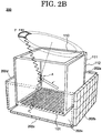
- Figure 2B shows the schematic arrangement of the detection module 202.
- the detection module 202 is provided to surround the radiation detection device 100 from five directions.
- the detection module has five portions 202a to 202e. Note that the detection module need not always be installed to surround the radiation detection device from five directions and may be installed in conformity with a specimen (radiation source) in the examination apparatus, as needed. For example, a detection module may be provided in only one direction.
- the radiation detection device 100 has the chamber 111.
- a gas mixture of a rare gas such as argon or xenon and an alkane gas (a chain saturate hydrocarbon represented by the general formula C n H 2n+2 ) at room temperature such as ethane or methane or a gas having a quenching effect (quenching gas) including carbon dioxide is introduced into the chamber 111.
- a gas or gases to be mixed with a rare gas may include either or both of a gas such as ethane or methane and a gas having a quenching effect including carbon dioxide.
- the pixel electrode portion 101 on which a plurality of pixels is two-dimensionally laid out is provided on the bottom surface of the chamber 111.
- the drift electrode 110 is provided on the upper surface of the chamber 111.
- Drift cages 112 are provided on side surfaces of the chamber 111. The drift cages 112 are provided to homogenize the electric field distribution between the drift electrode 110 and the pixel electrode portion 101.
- Information representing the energy of the scattered ⁇ ray and the incident position and incident time of the scattered ⁇ ray is provided to the controller 310. With this operation, an image is reconstructed within the limited energy range conceivable when radiation from a radiation source is scattered only once in the chamber 111, and hence the noise removing ability (noise removal by energy discrimination) can be improved.
- the gas in the chamber 111 which has collided with the incident ⁇ ray emits a recoil electron e - (charged particle) from the position denoted by reference symbol "A" in a predetermined direction.
- An electron cloud is then generated along the track of the recoil electron.
- the electrons constituting the electron cloud are attracted to the pixel electrode portion 101 due to an electric field between the drift electrode 110 and the pixel electrode portion 101.
- An electron that has been attracted near to the electrode portion 101 collides with the gas due to a high electric field near the pixel electrode portion 101 to ionize the gas. Ionized electrons proliferate in an avalanche-like manner and are detected by the pixel electrode portion 101.
- the electrical signal obtained in this manner corresponds to the detection signal S2 shown in Figure 1 , and information representing the capturing position and capturing time of each electron is provided to the controller 310.
- the detection signal S2 is a signal that makes it possible to specify the position of a pixel that has detected the electron and the time when the pixel has detected the electron.
- the time between the instant when a scattered ⁇ ray enters the detection module 202 and the instant when an electron is detected by the pixel electrode portion 101 makes it possible to calculate the distance from the pixel electrode portion 101 to the position at which an electron cloud is generated (the position in the z direction).
- the controller 310 is triggered by the activation of the detection signal S1 (the incidence of a scattered ⁇ ray on the detection module 202) to chronologically analyze the detection signal S2 and calculate the track of a recoil electron by using the position of a pixel that has detected an electron and the time when the pixel has detected the electron (to be sometimes referred to as a detection time hereinafter).
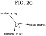
- the detection time (to be sometimes referred to as a drift time hereinafter) corresponds to the time from the instant when the controller 310 is triggered to the instant when an electron is detected by the pixel electrode portion 101. Calculating also an angle ⁇ shown in Figure 2C can specify the direction in which the incident ⁇ ray has entered.
- the controller 310 acquires three-dimensional coordinates indicating the position of a radiation source from the direction specified in this manner.
- the controller 310 also acquires a count rate representing the intensity of the radiation source from the detection signals S1 and S2.
- Four-dimensional data constituted by the three-dimensional coordinates acquired in this manner and the count rate is an indicated value from the Compton camera 200.
- the pixel electrode portion 101 includes the insulating member 102, the cathode electrodes 104, the anode electrodes 106, and the anode electrode patterns 108.
- the plurality of cathode electrodes 104 extend in the y direction on the upper surface of the insulating member 102.
- the cathode electrode 104 is provided with the plurality of opening portions 105.
- the upper surface of the insulating member 102 is exposed in the opening portions 105.
- the anode electrodes 106 extend from the reverse surface of the insulating member 102 and penetrate through the insulating member 102 in the z direction. The tip ends of the anode electrodes 106 are exposed in the plurality of opening portions 105.
- the plurality of anode electrodes 106 arrayed in the y direction are respectively connected to the different anode electrode patterns 108.
- the plurality of anode electrode patterns 108 extend in the x direction on the reverse surface of the insulating member 102.
- the y direction in which the cathode electrodes 104 extend is almost perpendicular to the x direction in which the anode electrode patterns 108 extend.
- This embodiment has exemplified the mode in which the anode electrodes 106 and the anode electrode patterns 108 are separately provided and are electrically connected to each other. However, this is not exhaustive, and the anode electrodes 106 and the anode electrode patterns 108 may be integrally formed.
- a voltage is applied between the cathode electrode 104 and the anode electrode 106 to form an electric field.
- the anode electrode 106 captures an electron attracted to the pixel electrode portion 101 due to this electric field. This pixel then detects the electron.
- the drift electrode 110 has an xy plane is separated from the xy plane forming the pixel electrode portion 101 by a predetermined distance in the z direction. A voltage is applied between the drift electrode 110 and the cathode electrode 104 and the anode electrode 106 to form an electric field.
- the radiation detection device 100 has the above arrangement, in which the anode electrodes 106 are arranged in a matrix pattern in the pixel electrode portion 101.
- the anode electrode 106 exposed on the upper surface of the insulating member 102 forms one pixel.
- Chronologically analyzing changes in the voltages of electrical signals appearing in the plurality of cathode electrodes 104 and the plurality of anode electrode patterns 108 can specify the positions of pixels that have detected electrons and the detection times of the electrons, thus obtaining electron detection results at the respective pixels. As has been described above, this makes it possible to calculate the track of a recoil electron.
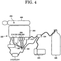
- Figure 4 is a schematic view showing a nuclear medicine examination apparatus 300 and its peripheral devices shown in Figure 1 . As shown in Figure 4 , the nuclear medicine examination apparatus 300 is used to specify the position of a radiation source 450 embedded in a human body 400.
- a controller 310, an input device 312, and an output device 314, which are shown in Figure 1 are implemented by a computer.
- the controller 310 is formed from a CPU provided in this computer.
- the input device 312 is formed from an input device such as a keyboard, mouse, or the like provided for this computer.
- the output device 314 is formed from a display device such as a display provided for the computer.
- the nuclear medicine examination apparatus 300 is provided with various types of sensors including a pressure sensor 204, a temperature sensor 206, and a mass analyzer 208, a radiation sensor signal detector 210, an electromagnetic valve 212, and a temperature control mechanism 214. They are connected to the controller 310 via a hub 322.
- the pressure sensor 204 is a sensor that measures the pressure in a chamber 111 of a radiation detection device 100 shown in Figures 2A and 2B .
- An output signal from the pressure sensor 204 is supplied to the controller 310 via the hub 322.
- an absolute pressure instrument that can measure an absolute pressure such as a diaphragm vacuum meter is preferably used. Note, however, that even a differential pressure instrument that cannot measure an absolute pressure by itself can be used as the pressure sensor 204 when an absolute pressure instrument is provided to use indicated values from the differential pressure instrument and the absolute pressure instrument in synchronism with each other.
- the temperature sensor 206 is a sensor that measures the temperature in the chamber 111. An output signal from the temperature sensor 206 is supplied to the controller 310 via the hub 322.
- the temperature sensor 206 may be provided in the chamber 111 or on the outer surface of the chamber 111. As a specific example of the temperature sensor 206, a K- or T-type thermocouple is preferably used.
- the mass analyzer 208 is a sensor that measures the composition ratio of each gas in the chamber 111.
- the mass analyzer 208 samples the gas in the chamber 111 and a gas mixture of a rare gas in the chamber 111 and a gas having a quenching effect (quenching gas), thus performing mass analysis.
- An output signal from then mass analyzer 208 is supplied to the controller 310 via the hub 322.
- the radiation sensor signal detector 210 has a function of generating the detection signals S1 and S2 described above.
- the detection signals S1 and S2 generated by the radiation sensor signal detector 210 are supplied to the controller 310 via the hub 322.
- the electromagnetic valve 212 is connected to a gas cylinder 326 and a vacuum pump 324 via an electromagnetic regulator branch valve 328.
- the gas cylinder 326 is filled with a rare gas and a gas having a quenching effect (quenching gas).
- quenching gas quenching gas
- the gas cylinder 326 is filled with a gas mixture containing argon and ethane at a ratio of 9 : 1.
- the electromagnetic regulator branch valve 328 is connected to the controller 310 via the hub 322, and the electromagnetic valve 212 and the electromagnetic regulator branch valve 328 are configured to open and close under the control of the controller 310.
- the temperature control mechanism 214 has a function of controlling the temperature in the chamber 111 under the control of the controller 310. More specifically, the temperature control mechanism 214 may be either or both of a heating mechanism and a cooling mechanism. As the heating mechanism, for example, a heating wire is preferably used. On the other hand, as the cooling mechanism, for example, an air-cooling mechanism using a fan or a water-cooling mechanism obtained by passing water through a tube is preferably used. The specific installation place of the temperature control mechanism 214 may be inside or outside the chamber 111.
- the nuclear medicine examination apparatus 300 is further provided with a high-voltage power supply 320.
- the high-voltage power supply 320 has a function of generating high-voltage power under the control of the controller 310 and supplying the power as operating power to the Compton camera 200.
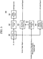
- FIG. 5 is a schematic block diagram showing the function blocks of the controller 310.
- the controller 310 functionally includes a gas state control unit 350, an information acquisition unit 352, a driving condition control unit 354, a signal synchronization unit 360, a correction unit 362, and an image acquisition unit 364.
- the gas state control unit 350 is a functional unit that controls a gas state in the chamber 111 shown in Figures 2A and 2B (controls at least one of physical amounts such as a temperature and a pressure and a composition) on the basis of output signals from various types of sensors shown in Figure 4 (the pressure sensor 204, the temperature sensor 206, and the mass analyzer 208). More specifically, gas state control by the gas state control unit 350 includes controlling the pressure in the chamber 111 on the basis of an output signal from the pressure sensor 204, controlling the temperature in the chamber 111 on the basis of an output signal from the temperature sensor 206, and controlling the composition ratio of the gas in the chamber 111 on the basis of an output signal from the mass analyzer 208. Each control operation will be described in detail below.
- Figure 6 shows a temporal change in the dose of radiation from the radiation source 450, and desired values of pressure control by the gas state control unit. 350.
- the dose of radiation from the radiation source 450 exhibits the property of decreasing in inverse proportion to the lapse of time.
- the probability of Compton scattering decreases. This makes it difficult for the image acquisition unit 364 to reconstruct a three-dimensional image and specify the position of the radiation source 450. For this reason, the gas state control unit 350 raises the pressure in the chamber 111 with the lapse of time.
- the gas state control unit 350 monitors the pressure in the chamber 111 in accordance with an output signal from the pressure sensor 204, and controls the electromagnetic valve 212 and the electromagnetic regulator branch valve 328, thereby raising the pressure in the chamber 111.
- the pressure in the chamber 111 is set to 1.0 atm for first 5 min, and the pressure in the chamber 111 is set to 1.5 atm for next 10 min. Subsequently, the pressure in the chamber 111 is set to 2.0 atm.
- Raising the pressure of a gas in the chamber 111 makes it possible to properly specify the position of the radiation source 450 even if the dose of radiation from the radiation source 450 is low.
- raising the pressure of a gas while the dose of radiation is high tends to cause abnormal discharge at the pixel electrode portion 101.
- the gas state control unit 350 gradually raises the pressure in the chamber 111 with the lapse of time as described above, and hence can specify the position of the radiation source 450 with a predetermined efficiency over a long period of time while preventing the occurrence of such abnormal discharge.
- the gas state control unit 350 operates to keep the temperature in the chamber 111 constant by controlling the temperature control mechanism 214 while monitoring the temperature in the chamber 111 in accordance with an output signal from the temperature sensor 206. This can keep the temperature in the chamber 111 constant and hence can specify the position of the radiation source 450 with a predetermined efficiency over a long period of time.
- the gas state control unit 350 operates to keep the composition ratio of the gas in the chamber 111 constant by controlling the electromagnetic valve 212 and the electromagnetic regulator branch valve 328 while monitoring the composition ratio of the gas in the chamber 111 in accordance with an output signal from the mass analyzer 208.
- the gas in the chamber 111 deteriorates with the lapse of time, and the composition ratio of the gas changes.
- performing such control can keep the composition ratio of the gas in the chamber 111 constant, and hence can specify the position of the radiation source 450 with a predetermined efficiency over a long period of time.
- the information acquisition unit 352 is a functional unit that acquires information concerning at least one of the following information: the nuclide and dose data of the radiation source 450, a measurement region in the human body 400, and an imaging angle (the angle of the Compton camera 200 with respect to the human body 400).
- the nuclide of the radiation source 450, a measurement region in the human body 400, and an imaging angle may be set in the controller 310 by the user.
- the dose data of the radiation source 450 may be sequentially acquired from the above count rate or may be sequentially acquired from output data from a dosimeter that is provided separately from the Compton camera 200.
- the information acquired by the information acquisition unit 352 is supplied to the gas state control unit 350.
- the gas state control unit 350 stores the contents of the information supplied from the information acquisition unit 352 in association with the specific contents of each control operation described above, and acquires the specific contents of the respective control operations on the basis of the information supplied to the gas state control unit 350.
- the gas state control unit 350 then executes each control operation in accordance with the acquired contents. That is, because the specific contents of control performed by the gas state control unit 350 are automatically adjusted on the basis of the information acquired by the information acquisition unit 352, the position of the radiation source 450 can be specified with constant quality regardless of the skill of an imaging technician.
- the driving condition control unit 354 is a functional unit that controls driving conditions for the Compton camera 200 shown in Figure 4 on the basis of output signals from the respective types of sensors shown in Figure 4 (the pressure sensor 204, the temperature sensor 206, and the mass analyzer 208).
- the driving conditions in this case include the potential of the anode electrode 106 and the potential of the drift electrode 110 shown in, for example, Figure 3 .
- the driving condition control unit 354 lowers the potential of the anode electrode 106 to restrict the occurrence of discharge and also restrict an increase in the gain of avalanche amplification.
- the driving condition control unit 354 can adjust a region for making a recoil electron drift by controlling the potential of the drift electrode 110 on the basis of output signals from various types of sensors.
- the driving condition control unit 354 can control the Compton camera 200 in a desired state by controlling driving conditions for the Compton camera 200 on the basis of output signals from various types of sensors in this manner. This control, therefore, makes it possible to specify the position of the radiation source 450 with constant quality.
- the signal synchronization unit 360 is a functional unit that associates output signals from the respective types of sensors shown in Figure 4 (the pressure sensor 204, the temperature sensor 206, and the mass analyzer 208) with the detection signals S1 and S2 from the Compton camera 200 described above. With the processing performed by the signal synchronization unit 360, output signals from various types of sensors at different times are associated with the detection signals S1 and S2 sequentially supplied from the Compton camera 200 in a chronological order.
- the correction unit 362 is a functional unit that corrects the detection signals S1 and S2 sequentially supplied from the Compton camera 200 in a chronological order on the basis of output signals from the respective types of sensors associated with the detection signals S1 and S2. Although the detection signals S1 and S2 from the Compton camera 200 are influenced by the pressure, temperature, and gas composition ratio in the chamber 111, the correction unit 362 can remove such influences from the detection signals S1 and S2 by performing the above correction.
- the image acquisition unit 364 is a functional unit that acquires an image on the basis of the detection signals S1 and S2 corrected by the correction unit 362. More specifically, a three-dimensional image is reconstructed by computation based on the detection signals S1 and S2. The image obtained in this manner is presented to the operator via the output device 314 shown in Figure 1 , as described above.
- the nuclear medicine examination apparatus 300 can specify the position of the radiation source 450 with a constant efficiency over a long period of time because the gas state control unit 350 controls a gas state in the chamber 111 on the basis of output signals from the respective types of sensors (the pressure sensor 204, the temperature sensor 206, and the mass analyzer 208).
- the specific contents of control performed by the gas state control unit 350 are automatically determined on the basis of the information acquired by the information acquisition unit 352, the position of the radiation source 450 can be specified with constant quality regardless of the skill of an imaging technician.
- the correction unit 362 can eliminate the influences of the pressure, temperature, and gas composition ratio in the chamber 111 from the detection signals S1 and S2 by making the correction unit 362 correct the detection signals S1 and S2.
- Control of a gas state by the gas state control unit 350 and correction of the detection signals S1 and S2 by the correction unit 362 will be described in detail again with reference to a processing procedure for the controller 310.
- FIG. 7 is a flowchart showing a processing procedure for control of a gas state by the gas state control unit 350.
- this processing procedure exemplifies a case in which the dose data of the radiation source 450 is used as information acquired by the information acquisition unit 352.
- the gas state control unit 350 sets a variable N to 0 (step S1).
- the gas state control unit 350 then performs a receiving operation with respect to output signals (to be referred to as "gas characteristic signals" hereinafter) from the respective types of sensors (step S2).
- the gas state control unit 350 determines whether the receiving operation has succeeded (step S3).
- step S3 Upon determining in step S3 that the receiving operation has failed, the gas state control unit 350 increments the variable N by 1 (step S4), and determines whether the variable N has exceeded 10 (step S5). If NO in step S5, the gas state control unit 350 executes a receiving operation for a gas characteristic signal upon returning to step S2. If YES in step S5, the gas state control unit 350 displays "Err: gas characteristic detection disabled" on the output device 314 shown in Figure 1 (step S6). The processing is terminated. In this case, gas control is not executed.
- the gas state control unit 350 Upon determining in step S3 that the receiving operation has succeeded, the gas state control unit 350 reads immediately preceding dose data from the information acquisition unit 352 (step S7), and computes a desired value of control (to be referred to as a "gas control value” hereinafter) by using the read dose data and the gas characteristic signal received in step S2 (step S8).
- the information acquisition unit 352 determines whether the gas control value is included in a settable range (step S9). Upon determining that the gas control value is not included in the range, the information acquisition unit 352 displays "Pass: gas control not required" on the output device 314 shown in Figure 1 (step S10), and terminates the processing. In this case as well, the gas state control unit 350 does not execute gas control.
- the gas state control unit 350 Upon determining in step S9 that the gas control value is included, the gas state control unit 350 makes the user input information indicating whether gas control is necessary (step S11). This processing is preferably configured to make the user input information indicating whether control is necessary via the input device 312 upon presenting the settable range of gas control values to the output device 314 shown in Figure 1 .
- step S11 If the user inputs information indicating that gas control is not unnecessary in step S11, the gas state control unit 350 displays "gas control not executed" on the output device 314 shown in Figure 1 (step S13), and terminates the processing. In this case as well, the gas state control unit 350 does not execute gas control.
- step S11 if the user inputs information indicating that gas control is necessary in step S11, the gas state control unit 350 executes gas control so as to implement gas control values computed in step S8 (step S12).
- step S12 the gas state control unit 350 then displays "gas control executed" on the output device 314 shown in Figure 1 (step S14), and terminates the processing.
- the gas state control unit 350 can execute gas control by performing processing based on the processing procedure in Figure 7 .
- FIG 8 is a flowchart showing a processing procedure for correction of the detection signals S1 and S2 (to be referred to as "radiation characteristic signals” hereinafter) by the correction unit 362.
- the correction unit 362 sets variables S and N to 0 (step S21).
- the correction unit 362 then performs a receiving operation for a gas characteristic signal (step S22), and then determines whether the receiving operation has succeeded (step S23).
- step S24 Upon determining in step S23 that the receiving operation has failed, the correction unit 362 increments the variable N by 1 (step S24), and determines whether the variable N has exceeded 10 (step S25). If NO in step S25, the correction unit 362 returns to step S22 to execute a receiving operation for a gas characteristic signal again. If YES in step S25, the correction unit 362 displays "Err: gas characteristic detection disabled" on the output device 314 shown in Figure 1 (step S26), and terminates the processing. In this case, the correction unit 362 executes no radiation characteristic signal correction.
- step S23 Upon determining in step S23 that the receiving operation has succeeded, the correction unit 362 performs a receiving operation for radiation characteristic signals (step S27), and determines whether the receiving operation has succeeded (step S28).
- step S28 Upon determining in step S28 that the receiving operation has failed, the correction unit 362 increments the variable S by 1 (step S29), and determines whether the variable S has exceeded 10 (step S30). If NO in step S30, the correction unit 362 returns to step S27 to execute a receiving operation for radiation characteristic signals again. If YES in step S30, the correction unit 362 displays "Err: radiation detection disabled" on the output device 314 shown in Figure 1 (step S31), and terminates the processing. In this case as well, the correction unit 362 executes no radiation characteristic signal correction.
- the correction unit 362 Upon determining in step S28 that the receiving operation has succeeded, the correction unit 362 makes the user input information indicating whether radiation characteristic signal correction is necessary (step S32). This processing is preferably configured to make the user input information indicating whether correction is necessary via the input device 312.
- the correction unit 362 displays "correction not executed" on the output device 314 shown in Figure 1 (step S33), and terminates the processing. In this case as well, the correction unit 362 executes no radiation characteristic signal correction.
- step S32 If the user inputs information indicating that correction is necessary in step S32, the correction unit 362 executes correction of the radiation characteristic signals received in step S27 on the basis of the gas characteristic signal received in step S22 (step S34). The correction unit 362 then displays "correction executed" on the output device 314 shown in Figure 1 (step S35), and terminates the processing.
- the correction unit 362 can execute correction of radiation characteristic signals by processing based on the processing procedure shown in Figure 8 .
- output signals from the respective types of sensors may be output to the output device 314 shown in Figure 1 to allow the operator to visually check the measurement values of these sensors. This allows the operator to manually control a gas in the chamber 111.
- This embodiment regards all the pressure, temperature, and gas composition ratio in the chamber 111 as control targets of the gas state control unit 350, but only some of them may be control targets.
- the gas state control unit 350 performs gas control
- the driving condition control unit 354 performs driving condition control
- the correction unit 362 performs correction of the detection signals S1 and S2.
- the embodiment may be configured to execute only some of these control operations.
- Figure 6 shows an example of intermittently (stepwisely) controlling the pressure in the chamber 111.
- the gas state control unit 350 may continuously control the pressure in the chamber 111. This applies to temperature and gas composition ratio.
- the chamber 111 of the radiation detection device 100 may be detachable.
- the detection element 100a may be configured to be detachable from the chamber 111. If, for example, the anode electrode 106 has deteriorated, the detection element 100a may be configured to be detachable and replaceable.
- FIG 9 is a schematic view showing a nuclear medicine examination apparatus 300 (see Figure 1 ) and its peripheral devices according to the second embodiment.
- the nuclear medicine examination apparatus 300 includes a plurality of Compton cameras 200 and a plurality of gas cylinders 326.
- Each gas cylinder 326 is filled with a gas mixture containing a rare gas and a gas having a quenching effect (quenching gas) at a predetermined ratio.
- Figure 9 shows, for example, two Compton cameras 200a and 200b and two gas cylinders 326a and 326b. However, the numbers of them are not limited to two.
- the peripheral devices of the Compton camera 200 are basically provided for each Compton camera 200. More specifically, various types of sensors including a pressure sensor 204, a temperature sensor 206, and a mass analyzer 208, a radiation sensor signal detector 210, an electromagnetic valve 212, a temperature control mechanism 214, a high-voltage power supply 320, and a hub 322 are provided for each Compton camera 200. On the other hand, an electromagnetic regulator branch valve 328 and a vacuum pump 324 are provided commonly for each Compton camera 200. In addition, a computer constituted by a controller 310, an input device 312, and an output device 314 is provided commonly for each Compton camera 200.
- the controller 310 controls at least one of the electromagnetic valve 212, the electromagnetic regulator branch valve 328, and the temperature control mechanism 214 so as to set gases contained in the chamber 111 of each Compton camera 200 in different states.
- Figure 10 shows the relationship between a temporal change in the dose of radiation from a radiation source 450 and an example of control contents for gases by a gas state control unit 350.
- three Compton cameras 200a to 200c are incorporated in the nuclear medicine examination apparatus 300.
- the three gas cylinders 326 are prepared and respectively filled with a gas mixture containing argon and ethane at a ratio of 9 : 1, a gas mixture containing krypton and ethane at a ratio of 9 : 1, and a gas mixture containing xenon and ethane at a ratio of 9 : 1.
- the controller 310 controls the electromagnetic regulator branch valve 328 and the electromagnetic valves 212 of the Compton cameras 200a to 200c to fill the chamber 111 of the Compton camera 200a with a gas mixture containing argon and ethane at a ratio of 9 : 1, the chamber 111 of the Compton camera 200b with a gas mixture containing krypton and ethane at a ratio of 9 : 1, and the chamber 111 of the Compton camera 200c with a gas mixture containing xenon and ethane at a ratio of 9 : 1.
- the position of the radiation source 450 is specified while the Compton cameras 200a to 200c are sequentially switched with the lapse of time. More specifically, the position of the radiation source 450 is specified by the Compton camera 200a for the first 5 min, specified by the Compton camera 200b for the next 10 min, and specified by the Compton camera 200c afterward.
- the reactive cross-sections of argon, krypton, and xenon increase in this order.
- using a gas with a large reactive cross-section increases the probability that two or more electron clouds will be simultaneously generated with an increase in drift time.
- using a gas with a large reactive cross-section (a gas mixture containing xenon and ethane at a ratio of 9 : 1) in a high-dose state will make it difficult to specify the position of the radiation source 450.
- Gradually increasing the reactive cross-section of the filled gas by switching the Compton cameras 200 with the lapse of time as described above makes it possible to specify the position of the radiation source 450 with a constant efficiency while preventing an excessive increase in the probability that two or more electron clouds will be simultaneously generated.
Landscapes
- Health & Medical Sciences (AREA)
- Life Sciences & Earth Sciences (AREA)
- Physics & Mathematics (AREA)
- Molecular Biology (AREA)
- High Energy & Nuclear Physics (AREA)
- Engineering & Computer Science (AREA)
- Medical Informatics (AREA)
- General Physics & Mathematics (AREA)
- Spectroscopy & Molecular Physics (AREA)
- Nuclear Medicine, Radiotherapy & Molecular Imaging (AREA)
- Optics & Photonics (AREA)
- General Health & Medical Sciences (AREA)
- Biomedical Technology (AREA)
- Heart & Thoracic Surgery (AREA)
- Pathology (AREA)
- Radiology & Medical Imaging (AREA)
- Biophysics (AREA)
- Surgery (AREA)
- Animal Behavior & Ethology (AREA)
- Public Health (AREA)
- Veterinary Medicine (AREA)
- Measurement Of Radiation (AREA)
- Nuclear Medicine (AREA)
- Electron Tubes For Measurement (AREA)
Abstract
Description
- The present invention relates to a nuclear medicine examination apparatus incorporating a Compton camera.
- A radiation detection device (micro pixel gas chamber (MPGC)) using gas amplification by pixel-type electrodes has been studied. A radiation detection device using MPGC is combined with a scintillator to form an electron-tracking Compton camera (ETCC). A Compton camera of this type is featured to be able to implement imaging of a detection region that has insufficiently been imaged by radiation detection using a conventional detector (scintillator and semiconductor detector).
-
PTL 1 discloses an example of the structure of a radiation detection device using MPGC. PTL 2 also discloses an example of a Compton camera using a micros strip gas chamber (MSGC) instead of MPGC. -
- PTL 1: Japanese Patent No.
3354551 - PTL 2: Japanese Patent No.
3535045 - The above described Compton camera is sometimes used as a nuclear medicine examination apparatus for executing a nuclear medicine examination called PET (Positron Emission Tomography) or SPECT (Single Photon Emission CT). In this case, a radiation source is a radioactive material embedded in the body of a patient. As a radioactive material to be administered into the human body, a material having a relatively short half-life is generally used to minimize the influence of radiation exposure. For this reason, in some cases, the intensity of radiation significantly decreases during an examination, resulting in failure to clearly specify the position of a radiation source.
- To solve this problem, the sensitivity of a Compton camera may be increased to make it possible to clearly specify the position of a radiation source in spite of a reduction in the intensity of radiation. Specific methods for increasing the sensitivity include increasing the pressure of a gas, increasing the volume of a sensitive area by increasing the capacity of a chamber (increasing drift), and using a gas having a large reactive cross-section.
- However, increasing the pressure of a gas or using a gas having a large reactive cross-section tends to cause abnormal discharge at a pixel-type electrode. In addition, increasing the capacity of a chamber or using a gas having a large reactive cross-section will prolong the drift time. This increases the probability that before the electron cloud generated by the scattering of the first incident ray finishes drifting, an electron cloud is generated by the scattering of the second incident ray and starts drifting. When two or more electron clouds are simultaneously generated in this manner, it is difficult to specify the position of the radiation source. In addition, even increasing the reactive cross-section will not prolong the drift time. This tends to cause abnormal discharge.
- It is an object of the present invention to provide a nuclear medicine examination apparatus that can specify the position of a radiation source with a predetermined efficiency over a long period of time.
- A nuclear medicine examination apparatus according to an embodiment of the present invention is a nuclear medicine examination apparatus including a pixel-type radiation detection device configured to detect information of a charged particle generated by Compton scattering in a gas, one or a plurality of sensors configured to detect a physical amount of the gas in a chamber and a controller configured to control at least one of the physical amount and a composition of the gas based on output signals from the one or plurality of sensors.
- The one or plurality of sensors may include a pressure sensor configured to detect a pressure of the gas, and control of at least one of the physical amount and composition of the gas by the controller may include controlling the pressure of the gas based on an output signal from the pressure sensor.
- The one or plurality of sensors may include a temperature sensor configured to detect a temperature of the gas. In addition, the nuclear medicine examination apparatus may include a temperature control mechanism configured to control the temperature of the gas, and control of the physical amount of the gas by the controller may include controlling the temperature of the gas to a desired predetermined value by controlling the temperature control mechanism based on an output signal from the temperature sensor.
- The one or plurality of sensors may include a mass analyzer configured to detect a composition ratio of the gas. In addition, control of the composition of the gas by the controller may include controlling the composition ratio of the gas based on an output signal from the mass analyzer. Furthermore, the nuclear medicine examination apparatus may include a chamber into which the gas is introduced.
- The controller may include a signal synchronization unit configured to associate an output signal from the one or plurality of sensors with a indicated value from the pixel-type radiation detection device, a correction unit configured to correct the indicated value based on a corresponding output signal from the one or plurality of sensors, and an image acquisition unit configured to acquire an image based on an indicated value corrected by the correction unit.
- The controller may include a driving condition control unit configured to control a driving condition for the pixel-type radiation detection device based on an output signal from the one or plurality of sensors.
- The pixel-type radiation detection device may include a first pixel-type radiation detection device configured to detect information of a charged particle generated by Compton scattering in a first gas and a second pixel-type radiation detection device configured to detect information of a charged particle generated by Compton scattering in a second gas different in composition from the first gas.
- The controller may include an information acquisition unit configured to acquire information concerning at least one of a nuclide and a dose of a radiation source, a measurement region, and an imaging angle and continuously or intermittently may control a physical amount and composition of the gas based on information acquired by the information acquisition unit.
- According to an embodiment of the present invention, there is provided a nuclear medicine examination method of specifying a position of a radiation source emitted from a specimen by detecting a charged particle generated by Compton scattering in a gas. The method includes adjusting a pressure of a gas that causes the Compton scattering when detecting radiation emitted from the radiation source.
- The pressure of a gas generated by the Compton scattering may be increased with a reduction in dose of radiation emitted from the radiation source. The pressure of a gas generated by the Compton scattering may be increased with a lapse of time.
- Control may be performed to keep a temperature of a gas generated by the Compton scattering constant. Control may be performed to keep a composition ratio of a gas generated by the Compton scattering constant.
- According to an embodiment of the present invention, there is provided a nuclear medicine examination method of specifying a position of a radiation source emitted from a specimen by detecting a charged particle generated by Compton scattering in a gas. The method includes adjusting a type of gas that causes the Compton scattering when detecting radiation emitted from the radiation source.
- A gas that causes the Compton scattering may include a gas mixture of a rare gas and a gas having a quenching effect, and the type of rare gas may be adjusted. The gas that causes the Compton scattering may include a gas mixture of a rare gas and a gas having a quenching effect, and the rare gas may be changed to a rare gas having a larger reactive cross-section with a reduction in dose of radiation emitted from the radiation source. The gas that causes the Compton scattering includes a gas mixture of a rare gas and a gas having a quenching effect, and the rare gas may be changed in an order of argon, krypton, and xenon with a reduction in dose of radiation emitted from the radiation source.
- According to an embodiment of the present invention, it is possible to provide a nuclear medicine examination apparatus that can specify the position of a radiation source with a predetermined efficiency over a long period of time.
-
-
Figure 1 is a block diagram showing the arrangement of a nuclear medicine examination apparatus; -
Figure 2A is a view showing the schematic arrangement of_a detection element of a radiation detection device; -
Figure 2B is a view showing the schematic arrangement of a Compton camera; -
Figure 2C is a view for explaining the relationship between an incident γ ray, a scattered γ ray, and a recoil electron; -
Figure 3 is a view showing the schematic arrangement of a radiation detection device; -
Figure 4 is a schematic view showing a nuclear medicine examination apparatus and its peripheral devices according to Example 1; -
Figure 5 is a schematic block diagram showing the function blocks of a controller; -
Figure 6 is a graph showing a temporal change in the dose of radiation from a radiation source and desired values of pressure control by a gas state control unit; -
Figure 7 is a flowchart showing a processing procedure for control of the physical amount of gas by the gas state control unit; -
Figure 8 is a flowchart showing a processing procedure for correction of detection signals S1 and S2 by a correction unit; -
Figure 9 is a schematic view showing a nuclear medicine examination apparatus and its peripheral devices according to second embodiment; and -
Figure 10 is a graph showing a temporal change in the dose of radiation from a radiation source and control details concerning a gas composition by a gas state control unit. - A nuclear medicine examination apparatus according to the present invention will be described in detail below with reference to the accompanying drawings. Note that the nuclear medicine examination apparatus according to the present invention is not limited to the following embodiments and can be variously modified and embodied. In all the embodiments, the same reference numerals denote the same constituent elements. Furthermore, for the sake of descriptive convenience, dimensional ratios in the accompanying drawings are sometimes different from actual ratios, and an illustration of some components is sometimes omitted from the drawings.
-
Figure 1 shows the configuration of a nuclearmedicine examination apparatus 300 according to present embodiment. The nuclearmedicine examination apparatus 300 includes aCompton camera 200, acontroller 310, aninput device 312, and anoutput device 314. In a medical site, the nuclearmedicine examination apparatus 300 is used to specify the position of a radiation source embedded in the body of a patient. As will be described below, theCompton camera 200 has a chamber in which an introduced gas exists (in other words, a chamber into which a gas is introduced), and specifies the position of a radiation source by detecting the information of a charged particle generated by Compton scattering in the gas. - The
controller 310 reconstructs a three-dimensional image by computation based on detection signals S1 and S2 output from theCompton camera 200, and specifies the position of a radiation source. The operator can instruct thecontroller 310 by using theinput device 312. The three-dimensional image reconstructed by thecontroller 310 is presented to the operator via theoutput device 314. - The
Compton camera 200 is an ETCC and includes theradiation detection device 100 using MPGC and adetection module 202. Thedetection module 202 in this case includes photomultiplier tubes each of which converts emitted light when a scattered γ ray enters the scintillator into an electrical signal. Installing a plurality of photomultiplier tubes makes it possible to specify a light emission position. Assume that thedetection module 202 includes photomultiplier tubes in the following description. -
Figure 2A shows the schematic configuration of adetection element 100a of aradiation detection device 100. Theradiation detection device 100 includes thedetection element 100a having apixel electrode portion 101 and connecting terminal portions 109 (109a and 109b) and adrift electrode 110. Thedetection element 100a and thedrift electrode 110 are provided in achamber 111. Thedetection element 100a is an element including thepixel electrode portion 101 and the connecting terminal portions 109 (109a and 109b). - The
pixel electrode portion 101 of theradiation detection device 100 includes an insulatingmember 102,cathode electrodes 104,anode electrodes 106,anode electrode patterns 108, and asubstrate 130. The plurality ofcathode electrodes 104 are arranged on the first surface of the insulatingmember 102. Thecathode electrodes 104 have a plurality of openingportions 105. Thecathode electrode 104 is formed into a strip shape and hence is also called a cathode strip electrode. - The
anode electrode 106 is placed in a through hole provided in the insulatingmember 102 from the second surface on the opposite side to the first surface of the insulatingmember 102. In this embodiment, the tip ends of theanode electrodes 106 are exposed in the plurality of openingportions 105 in thecathode electrode 104. Referring toFigure 2A , eachanode electrode 106 has a shape with its tip end being exposed in a corresponding one of the openingportions 105. However, eachanode electrode 106 may be shaped such that its tip end is not exposed in a corresponding one of the opening portions 105 (including an anode electrode shaped such that its tip end is almost flush with the upper surface of the insulating member 102 (the upper surface of the through hole) or its tip end is located inside the through hole of the insulating member 102). - The plurality of
anode electrodes 106 placed in the plurality of openingportions 105 of onecathode electrode 104 are respectively connected to the plurality ofanode electrode patterns 108. Theanode electrode pattern 108 extends to the connectingterminal portion 109a. The direction in which thecathode electrode 104 extends is almost vertical to the direction in which theanode electrode pattern 108 extends. This embodiment has exemplified the mode in which theanode electrodes 106 and theanode electrode patterns 108 are separately provided and are electrically connected to each other. However, this is not exhaustive, and theanode electrodes 106 and theanode electrode patterns 108 to which therespective anode electrodes 106 are connected may be integrally formed. Eachanode electrode pattern 108 is formed into a strip shape and hence is also called an anode strip pattern. - The
wiring terminal portion 109a includes a viahole 126 connected to theanode electrode pattern 108 and ametal layer 120. Themetal layer 120 is connected to the viahole 126. AlthoughFigure 2A shows a case in which theanode electrode patterns 108 and the via holes 126 are separately formed, this is not exhaustive, and theanode electrode patterns 108 and the via holes 126 may be formed from the same metal material. Thewiring terminal portion 109b includes anelectrode 104a which is an extended portion of thecathode electrode 104. - With the above arrangement, the
radiation detection device 100 has theanode electrodes 106 arranged in a matrix pattern on thepixel electrode portion 101. That is, theradiation detection device 100 has a plurality of "pixels" arranged, each including theanode electrode 106 and a portion of thecathode electrode 104. In this arrangement, a voltage is applied between eachcathode electrode 104 and the correspondinganode electrode 106 to form an electric field. - The
drift electrode 110 is placed to face thepixel electrode portion 101. Thecathode electrodes 104 of thepixel electrode portion 101 are grounded, and a voltage is applied between thedrift electrode 110 and eachcathode electrode 104 to from an electric field. - The
chamber 111 encloses thepixel electrode portion 101, the connecting terminal portions 109, and thedrift electrode 110. A gas mixture of a rare gas such as argon or xenon and a molecular gas such as ethane or methane is introduced into thechamber 111. -
Figure 2B shows the schematic arrangement of thedetection module 202. As shown inFigure 2B , thedetection module 202 is provided to surround theradiation detection device 100 from five directions. In an example shown inFigure 2B , the detection module has five portions 202a to 202e. Note that the detection module need not always be installed to surround the radiation detection device from five directions and may be installed in conformity with a specimen (radiation source) in the examination apparatus, as needed. For example, a detection module may be provided in only one direction. - As shown in
Figure 2B , theradiation detection device 100 has thechamber 111. A gas mixture of a rare gas such as argon or xenon and an alkane gas (a chain saturate hydrocarbon represented by the general formula CnH2n+2) at room temperature such as ethane or methane or a gas having a quenching effect (quenching gas) including carbon dioxide is introduced into thechamber 111. A gas or gases to be mixed with a rare gas may include either or both of a gas such as ethane or methane and a gas having a quenching effect including carbon dioxide. Thepixel electrode portion 101 on which a plurality of pixels is two-dimensionally laid out is provided on the bottom surface of thechamber 111. Thedrift electrode 110 is provided on the upper surface of thechamber 111. Drift cages 112 are provided on side surfaces of thechamber 111. The drift cages 112 are provided to homogenize the electric field distribution between thedrift electrode 110 and thepixel electrode portion 101. - The following description concerns the principle of the
Compton camera 200. First of all, when a γ ray externally enters theradiation detection device 100, the incident γ ray collides with a gas in thechamber 111 and is scattered at a certain probability. Reference symbol "A" inFigure 2B denotes a collision position. The scattered γ ray whose propagation direction is changed by the collision is transmitted through theradiation detection device 100 and enters thedetection module 202. When the scattered γ ray enters thedetection module 202, light emission occurs. A photomultiplier tube then converts this emitted light into an electrical signal. The electrical signal obtained in this manner corresponds to the detection signal S1 shown inFigure 1 . Information representing the energy of the scattered γ ray and the incident position and incident time of the scattered γ ray is provided to thecontroller 310. With this operation, an image is reconstructed within the limited energy range conceivable when radiation from a radiation source is scattered only once in thechamber 111, and hence the noise removing ability (noise removal by energy discrimination) can be improved. - On the other hand, the gas in the
chamber 111 which has collided with the incident γ ray emits a recoil electron e- (charged particle) from the position denoted by reference symbol "A" in a predetermined direction. An electron cloud is then generated along the track of the recoil electron. The electrons constituting the electron cloud are attracted to thepixel electrode portion 101 due to an electric field between thedrift electrode 110 and thepixel electrode portion 101. An electron that has been attracted near to theelectrode portion 101 collides with the gas due to a high electric field near thepixel electrode portion 101 to ionize the gas. Ionized electrons proliferate in an avalanche-like manner and are detected by thepixel electrode portion 101. The electrical signal obtained in this manner corresponds to the detection signal S2 shown inFigure 1 , and information representing the capturing position and capturing time of each electron is provided to thecontroller 310. The detection signal S2 is a signal that makes it possible to specify the position of a pixel that has detected the electron and the time when the pixel has detected the electron. - Note that the time between the instant when a scattered γ ray enters the
detection module 202 and the instant when an electron is detected by thepixel electrode portion 101 makes it possible to calculate the distance from thepixel electrode portion 101 to the position at which an electron cloud is generated (the position in the z direction). - The
controller 310 is triggered by the activation of the detection signal S1 (the incidence of a scattered γ ray on the detection module 202) to chronologically analyze the detection signal S2 and calculate the track of a recoil electron by using the position of a pixel that has detected an electron and the time when the pixel has detected the electron (to be sometimes referred to as a detection time hereinafter). The detection time (to be sometimes referred to as a drift time hereinafter) corresponds to the time from the instant when thecontroller 310 is triggered to the instant when an electron is detected by thepixel electrode portion 101. Calculating also an angle α shown inFigure 2C can specify the direction in which the incident γ ray has entered. Thecontroller 310 acquires three-dimensional coordinates indicating the position of a radiation source from the direction specified in this manner. Thecontroller 310 also acquires a count rate representing the intensity of the radiation source from the detection signals S1 and S2. Four-dimensional data constituted by the three-dimensional coordinates acquired in this manner and the count rate is an indicated value from theCompton camera 200. - As shown in
Figure 3 , thepixel electrode portion 101 includes the insulatingmember 102, thecathode electrodes 104, theanode electrodes 106, and theanode electrode patterns 108. - The plurality of
cathode electrodes 104 extend in the y direction on the upper surface of the insulatingmember 102. Thecathode electrode 104 is provided with the plurality of openingportions 105. The upper surface of the insulatingmember 102 is exposed in the openingportions 105. - The
anode electrodes 106 extend from the reverse surface of the insulatingmember 102 and penetrate through the insulatingmember 102 in the z direction. The tip ends of theanode electrodes 106 are exposed in the plurality of openingportions 105. - The plurality of
anode electrodes 106 arrayed in the y direction are respectively connected to the differentanode electrode patterns 108. The plurality ofanode electrode patterns 108 extend in the x direction on the reverse surface of the insulatingmember 102. The y direction in which thecathode electrodes 104 extend is almost perpendicular to the x direction in which theanode electrode patterns 108 extend. This embodiment has exemplified the mode in which theanode electrodes 106 and theanode electrode patterns 108 are separately provided and are electrically connected to each other. However, this is not exhaustive, and theanode electrodes 106 and theanode electrode patterns 108 may be integrally formed. - A voltage is applied between the
cathode electrode 104 and theanode electrode 106 to form an electric field. Theanode electrode 106 captures an electron attracted to thepixel electrode portion 101 due to this electric field. This pixel then detects the electron. - The
drift electrode 110 has an xy plane is separated from the xy plane forming thepixel electrode portion 101 by a predetermined distance in the z direction. A voltage is applied between thedrift electrode 110 and thecathode electrode 104 and theanode electrode 106 to form an electric field. - The
radiation detection device 100 according to this embodiment has the above arrangement, in which theanode electrodes 106 are arranged in a matrix pattern in thepixel electrode portion 101. Theanode electrode 106 exposed on the upper surface of the insulatingmember 102 forms one pixel. Chronologically analyzing changes in the voltages of electrical signals appearing in the plurality ofcathode electrodes 104 and the plurality ofanode electrode patterns 108 can specify the positions of pixels that have detected electrons and the detection times of the electrons, thus obtaining electron detection results at the respective pixels. As has been described above, this makes it possible to calculate the track of a recoil electron. -
Figure 4 is a schematic view showing a nuclearmedicine examination apparatus 300 and its peripheral devices shown inFigure 1 . As shown inFigure 4 , the nuclearmedicine examination apparatus 300 is used to specify the position of aradiation source 450 embedded in ahuman body 400. - As shown in
Figure 4 , acontroller 310, aninput device 312, and anoutput device 314, which are shown inFigure 1 , are implemented by a computer. Thecontroller 310 is formed from a CPU provided in this computer. Theinput device 312 is formed from an input device such as a keyboard, mouse, or the like provided for this computer. Theoutput device 314 is formed from a display device such as a display provided for the computer. - The nuclear
medicine examination apparatus 300 is provided with various types of sensors including apressure sensor 204, atemperature sensor 206, and amass analyzer 208, a radiationsensor signal detector 210, anelectromagnetic valve 212, and atemperature control mechanism 214. They are connected to thecontroller 310 via ahub 322. - The
pressure sensor 204 is a sensor that measures the pressure in achamber 111 of aradiation detection device 100 shown inFigures 2A and2B . An output signal from thepressure sensor 204 is supplied to thecontroller 310 via thehub 322. As a specific example of thepressure sensor 204, for example, an absolute pressure instrument that can measure an absolute pressure such as a diaphragm vacuum meter is preferably used. Note, however, that even a differential pressure instrument that cannot measure an absolute pressure by itself can be used as thepressure sensor 204 when an absolute pressure instrument is provided to use indicated values from the differential pressure instrument and the absolute pressure instrument in synchronism with each other. - The
temperature sensor 206 is a sensor that measures the temperature in thechamber 111. An output signal from thetemperature sensor 206 is supplied to thecontroller 310 via thehub 322. Thetemperature sensor 206 may be provided in thechamber 111 or on the outer surface of thechamber 111. As a specific example of thetemperature sensor 206, a K- or T-type thermocouple is preferably used. - The
mass analyzer 208 is a sensor that measures the composition ratio of each gas in thechamber 111. Themass analyzer 208 samples the gas in thechamber 111 and a gas mixture of a rare gas in thechamber 111 and a gas having a quenching effect (quenching gas), thus performing mass analysis. An output signal from thenmass analyzer 208 is supplied to thecontroller 310 via thehub 322. - The radiation
sensor signal detector 210 has a function of generating the detection signals S1 and S2 described above. The detection signals S1 and S2 generated by the radiationsensor signal detector 210 are supplied to thecontroller 310 via thehub 322. - The
electromagnetic valve 212 is connected to agas cylinder 326 and avacuum pump 324 via an electromagneticregulator branch valve 328. Thegas cylinder 326 is filled with a rare gas and a gas having a quenching effect (quenching gas). For example, thegas cylinder 326 is filled with a gas mixture containing argon and ethane at a ratio of 9 : 1. The electromagneticregulator branch valve 328 is connected to thecontroller 310 via thehub 322, and theelectromagnetic valve 212 and the electromagneticregulator branch valve 328 are configured to open and close under the control of thecontroller 310. - The
temperature control mechanism 214 has a function of controlling the temperature in thechamber 111 under the control of thecontroller 310. More specifically, thetemperature control mechanism 214 may be either or both of a heating mechanism and a cooling mechanism. As the heating mechanism, for example, a heating wire is preferably used. On the other hand, as the cooling mechanism, for example, an air-cooling mechanism using a fan or a water-cooling mechanism obtained by passing water through a tube is preferably used. The specific installation place of thetemperature control mechanism 214 may be inside or outside thechamber 111. - The nuclear
medicine examination apparatus 300 is further provided with a high-voltage power supply 320. The high-voltage power supply 320 has a function of generating high-voltage power under the control of thecontroller 310 and supplying the power as operating power to theCompton camera 200. -
Figure 5 is a schematic block diagram showing the function blocks of thecontroller 310. As shown inFigure 5 , thecontroller 310 functionally includes a gasstate control unit 350, aninformation acquisition unit 352, a drivingcondition control unit 354, asignal synchronization unit 360, acorrection unit 362, and animage acquisition unit 364. - The gas
state control unit 350 is a functional unit that controls a gas state in thechamber 111 shown inFigures 2A and2B (controls at least one of physical amounts such as a temperature and a pressure and a composition) on the basis of output signals from various types of sensors shown inFigure 4 (thepressure sensor 204, thetemperature sensor 206, and the mass analyzer 208). More specifically, gas state control by the gasstate control unit 350 includes controlling the pressure in thechamber 111 on the basis of an output signal from thepressure sensor 204, controlling the temperature in thechamber 111 on the basis of an output signal from thetemperature sensor 206, and controlling the composition ratio of the gas in thechamber 111 on the basis of an output signal from themass analyzer 208. Each control operation will be described in detail below. - First of all, with regard to pressure,
Figure 6 shows a temporal change in the dose of radiation from theradiation source 450, and desired values of pressure control by the gas state control unit. 350. As shown inFigure 6 , the dose of radiation from theradiation source 450 exhibits the property of decreasing in inverse proportion to the lapse of time. As the dose of radiation from theradiation source 450 decreases, the probability of Compton scattering decreases. This makes it difficult for theimage acquisition unit 364 to reconstruct a three-dimensional image and specify the position of theradiation source 450. For this reason, the gasstate control unit 350 raises the pressure in thechamber 111 with the lapse of time. More specifically, the gasstate control unit 350 monitors the pressure in thechamber 111 in accordance with an output signal from thepressure sensor 204, and controls theelectromagnetic valve 212 and the electromagneticregulator branch valve 328, thereby raising the pressure in thechamber 111. In the case shown inFigure 6 , the pressure in thechamber 111 is set to 1.0 atm for first 5 min, and the pressure in thechamber 111 is set to 1.5 atm for next 10 min. Subsequently, the pressure in thechamber 111 is set to 2.0 atm. - Raising the pressure of a gas in the
chamber 111 makes it possible to properly specify the position of theradiation source 450 even if the dose of radiation from theradiation source 450 is low. On the other hand, as described above, raising the pressure of a gas while the dose of radiation is high tends to cause abnormal discharge at thepixel electrode portion 101. The gasstate control unit 350 gradually raises the pressure in thechamber 111 with the lapse of time as described above, and hence can specify the position of theradiation source 450 with a predetermined efficiency over a long period of time while preventing the occurrence of such abnormal discharge. - Subsequently, with regard to temperature, the gas
state control unit 350 operates to keep the temperature in thechamber 111 constant by controlling thetemperature control mechanism 214 while monitoring the temperature in thechamber 111 in accordance with an output signal from thetemperature sensor 206. This can keep the temperature in thechamber 111 constant and hence can specify the position of theradiation source 450 with a predetermined efficiency over a long period of time. - Subsequently, with regard to the composition ratio of the gas, the gas
state control unit 350 operates to keep the composition ratio of the gas in thechamber 111 constant by controlling theelectromagnetic valve 212 and the electromagneticregulator branch valve 328 while monitoring the composition ratio of the gas in thechamber 111 in accordance with an output signal from themass analyzer 208. The gas in thechamber 111 deteriorates with the lapse of time, and the composition ratio of the gas changes. However, performing such control can keep the composition ratio of the gas in thechamber 111 constant, and hence can specify the position of theradiation source 450 with a predetermined efficiency over a long period of time. - The
information acquisition unit 352 is a functional unit that acquires information concerning at least one of the following information: the nuclide and dose data of theradiation source 450, a measurement region in thehuman body 400, and an imaging angle (the angle of theCompton camera 200 with respect to the human body 400). Of these pieces of information, the nuclide of theradiation source 450, a measurement region in thehuman body 400, and an imaging angle may be set in thecontroller 310 by the user. The dose data of theradiation source 450 may be sequentially acquired from the above count rate or may be sequentially acquired from output data from a dosimeter that is provided separately from theCompton camera 200. - The information acquired by the
information acquisition unit 352 is supplied to the gasstate control unit 350. The gasstate control unit 350 stores the contents of the information supplied from theinformation acquisition unit 352 in association with the specific contents of each control operation described above, and acquires the specific contents of the respective control operations on the basis of the information supplied to the gasstate control unit 350. The gasstate control unit 350 then executes each control operation in accordance with the acquired contents. That is, because the specific contents of control performed by the gasstate control unit 350 are automatically adjusted on the basis of the information acquired by theinformation acquisition unit 352, the position of theradiation source 450 can be specified with constant quality regardless of the skill of an imaging technician. - The driving
condition control unit 354 is a functional unit that controls driving conditions for theCompton camera 200 shown inFigure 4 on the basis of output signals from the respective types of sensors shown inFigure 4 (thepressure sensor 204, thetemperature sensor 206, and the mass analyzer 208). The driving conditions in this case include the potential of theanode electrode 106 and the potential of thedrift electrode 110 shown in, for example,Figure 3 . - In some cases, if, for example, the pressure in the
chamber 111 is high, discharge occurs, and the gain of avalanche amplification becomes excessively high. If the pressure in thechamber 111 is high, the drivingcondition control unit 354 lowers the potential of theanode electrode 106 to restrict the occurrence of discharge and also restrict an increase in the gain of avalanche amplification. In addition, the drivingcondition control unit 354 can adjust a region for making a recoil electron drift by controlling the potential of thedrift electrode 110 on the basis of output signals from various types of sensors. The drivingcondition control unit 354 can control theCompton camera 200 in a desired state by controlling driving conditions for theCompton camera 200 on the basis of output signals from various types of sensors in this manner. This control, therefore, makes it possible to specify the position of theradiation source 450 with constant quality. - The
signal synchronization unit 360 is a functional unit that associates output signals from the respective types of sensors shown inFigure 4 (thepressure sensor 204, thetemperature sensor 206, and the mass analyzer 208) with the detection signals S1 and S2 from theCompton camera 200 described above. With the processing performed by thesignal synchronization unit 360, output signals from various types of sensors at different times are associated with the detection signals S1 and S2 sequentially supplied from theCompton camera 200 in a chronological order. - The
correction unit 362 is a functional unit that corrects the detection signals S1 and S2 sequentially supplied from theCompton camera 200 in a chronological order on the basis of output signals from the respective types of sensors associated with the detection signals S1 and S2. Although the detection signals S1 and S2 from theCompton camera 200 are influenced by the pressure, temperature, and gas composition ratio in thechamber 111, thecorrection unit 362 can remove such influences from the detection signals S1 and S2 by performing the above correction. - The
image acquisition unit 364 is a functional unit that acquires an image on the basis of the detection signals S1 and S2 corrected by thecorrection unit 362. More specifically, a three-dimensional image is reconstructed by computation based on the detection signals S1 and S2. The image obtained in this manner is presented to the operator via theoutput device 314 shown inFigure 1 , as described above. - As described above, the nuclear
medicine examination apparatus 300 according to this embodiment can specify the position of theradiation source 450 with a constant efficiency over a long period of time because the gasstate control unit 350 controls a gas state in thechamber 111 on the basis of output signals from the respective types of sensors (thepressure sensor 204, thetemperature sensor 206, and the mass analyzer 208). In addition, because the specific contents of control performed by the gasstate control unit 350 are automatically determined on the basis of the information acquired by theinformation acquisition unit 352, the position of theradiation source 450 can be specified with constant quality regardless of the skill of an imaging technician. In addition, it is possible to specify the position of theradiation source 450 with constant quality by making the drivingcondition control unit 354 control driving conditions for theCompton camera 200 on the basis of output signals from the respective types of sensors. In addition, thecorrection unit 362 can eliminate the influences of the pressure, temperature, and gas composition ratio in thechamber 111 from the detection signals S1 and S2 by making thecorrection unit 362 correct the detection signals S1 and S2. - Control of a gas state by the gas
state control unit 350 and correction of the detection signals S1 and S2 by thecorrection unit 362 will be described in detail again with reference to a processing procedure for thecontroller 310. -
Figure 7 is a flowchart showing a processing procedure for control of a gas state by the gasstate control unit 350. Note that this processing procedure exemplifies a case in which the dose data of theradiation source 450 is used as information acquired by theinformation acquisition unit 352. As shown inFigure 7 , first of all, the gasstate control unit 350 sets a variable N to 0 (step S1). The gasstate control unit 350 then performs a receiving operation with respect to output signals (to be referred to as "gas characteristic signals" hereinafter) from the respective types of sensors (step S2). The gasstate control unit 350 then determines whether the receiving operation has succeeded (step S3). - Upon determining in step S3 that the receiving operation has failed, the gas
state control unit 350 increments the variable N by 1 (step S4), and determines whether the variable N has exceeded 10 (step S5). If NO in step S5, the gasstate control unit 350 executes a receiving operation for a gas characteristic signal upon returning to step S2. If YES in step S5, the gasstate control unit 350 displays "Err: gas characteristic detection disabled" on theoutput device 314 shown inFigure 1 (step S6). The processing is terminated. In this case, gas control is not executed. - Upon determining in step S3 that the receiving operation has succeeded, the gas
state control unit 350 reads immediately preceding dose data from the information acquisition unit 352 (step S7), and computes a desired value of control (to be referred to as a "gas control value" hereinafter) by using the read dose data and the gas characteristic signal received in step S2 (step S8). Theinformation acquisition unit 352 determines whether the gas control value is included in a settable range (step S9). Upon determining that the gas control value is not included in the range, theinformation acquisition unit 352 displays "Pass: gas control not required" on theoutput device 314 shown inFigure 1 (step S10), and terminates the processing. In this case as well, the gasstate control unit 350 does not execute gas control. - Upon determining in step S9 that the gas control value is included, the gas
state control unit 350 makes the user input information indicating whether gas control is necessary (step S11). This processing is preferably configured to make the user input information indicating whether control is necessary via theinput device 312 upon presenting the settable range of gas control values to theoutput device 314 shown inFigure 1 . - If the user inputs information indicating that gas control is not unnecessary in step S11, the gas
state control unit 350 displays "gas control not executed" on theoutput device 314 shown inFigure 1 (step S13), and terminates the processing. In this case as well, the gasstate control unit 350 does not execute gas control. - In contrast to this, if the user inputs information indicating that gas control is necessary in step S11, the gas
state control unit 350 executes gas control so as to implement gas control values computed in step S8 (step S12). The gasstate control unit 350 then displays "gas control executed" on theoutput device 314 shown inFigure 1 (step S14), and terminates the processing. - As described above, the gas
state control unit 350 can execute gas control by performing processing based on the processing procedure inFigure 7 . -
Figure 8 is a flowchart showing a processing procedure for correction of the detection signals S1 and S2 (to be referred to as "radiation characteristic signals" hereinafter) by thecorrection unit 362. As shown inFigure 8 , thecorrection unit 362 sets variables S and N to 0 (step S21). Thecorrection unit 362 then performs a receiving operation for a gas characteristic signal (step S22), and then determines whether the receiving operation has succeeded (step S23). - Upon determining in step S23 that the receiving operation has failed, the
correction unit 362 increments the variable N by 1 (step S24), and determines whether the variable N has exceeded 10 (step S25). If NO in step S25, thecorrection unit 362 returns to step S22 to execute a receiving operation for a gas characteristic signal again. If YES in step S25, thecorrection unit 362 displays "Err: gas characteristic detection disabled" on theoutput device 314 shown inFigure 1 (step S26), and terminates the processing. In this case, thecorrection unit 362 executes no radiation characteristic signal correction. - Upon determining in step S23 that the receiving operation has succeeded, the
correction unit 362 performs a receiving operation for radiation characteristic signals (step S27), and determines whether the receiving operation has succeeded (step S28). - Upon determining in step S28 that the receiving operation has failed, the
correction unit 362 increments the variable S by 1 (step S29), and determines whether the variable S has exceeded 10 (step S30). If NO in step S30, thecorrection unit 362 returns to step S27 to execute a receiving operation for radiation characteristic signals again. If YES in step S30, thecorrection unit 362 displays "Err: radiation detection disabled" on theoutput device 314 shown inFigure 1 (step S31), and terminates the processing. In this case as well, thecorrection unit 362 executes no radiation characteristic signal correction. - Upon determining in step S28 that the receiving operation has succeeded, the
correction unit 362 makes the user input information indicating whether radiation characteristic signal correction is necessary (step S32). This processing is preferably configured to make the user input information indicating whether correction is necessary via theinput device 312. - If the user inputs information indicating that correction is not necessary in step S32, the
correction unit 362 displays "correction not executed" on theoutput device 314 shown inFigure 1 (step S33), and terminates the processing. In this case as well, thecorrection unit 362 executes no radiation characteristic signal correction. - If the user inputs information indicating that correction is necessary in step S32, the
correction unit 362 executes correction of the radiation characteristic signals received in step S27 on the basis of the gas characteristic signal received in step S22 (step S34). Thecorrection unit 362 then displays "correction executed" on theoutput device 314 shown inFigure 1 (step S35), and terminates the processing. - In this manner, the
correction unit 362 can execute correction of radiation characteristic signals by processing based on the processing procedure shown inFigure 8 . - Note that output signals from the respective types of sensors (the
pressure sensor 204, thetemperature sensor 206, and the mass analyzer 208) shown inFigure 4 may be output to theoutput device 314 shown inFigure 1 to allow the operator to visually check the measurement values of these sensors. This allows the operator to manually control a gas in thechamber 111. - This embodiment regards all the pressure, temperature, and gas composition ratio in the
chamber 111 as control targets of the gasstate control unit 350, but only some of them may be control targets. In addition, in the embodiment, the gasstate control unit 350 performs gas control, the drivingcondition control unit 354 performs driving condition control, and thecorrection unit 362 performs correction of the detection signals S1 and S2. However, the embodiment may be configured to execute only some of these control operations. -
Figure 6 shows an example of intermittently (stepwisely) controlling the pressure in thechamber 111. However, the gasstate control unit 350 may continuously control the pressure in thechamber 111. This applies to temperature and gas composition ratio. - Note that in an embodiment of the present invention, the
chamber 111 of theradiation detection device 100 may be detachable. In addition, thedetection element 100a may be configured to be detachable from thechamber 111. If, for example, theanode electrode 106 has deteriorated, thedetection element 100a may be configured to be detachable and replaceable. -
Figure 9 is a schematic view showing a nuclear medicine examination apparatus 300 (seeFigure 1 ) and its peripheral devices according to the second embodiment. The nuclearmedicine examination apparatus 300 includes a plurality ofCompton cameras 200 and a plurality ofgas cylinders 326. Eachgas cylinder 326 is filled with a gas mixture containing a rare gas and a gas having a quenching effect (quenching gas) at a predetermined ratio.Figure 9 shows, for example, twoCompton cameras gas cylinders - The peripheral devices of the
Compton camera 200 are basically provided for eachCompton camera 200. More specifically, various types of sensors including apressure sensor 204, atemperature sensor 206, and amass analyzer 208, a radiationsensor signal detector 210, anelectromagnetic valve 212, atemperature control mechanism 214, a high-voltage power supply 320, and ahub 322 are provided for eachCompton camera 200. On the other hand, an electromagneticregulator branch valve 328 and avacuum pump 324 are provided commonly for eachCompton camera 200. In addition, a computer constituted by acontroller 310, aninput device 312, and anoutput device 314 is provided commonly for eachCompton camera 200. - The
controller 310 controls at least one of theelectromagnetic valve 212, the electromagneticregulator branch valve 328, and thetemperature control mechanism 214 so as to set gases contained in thechamber 111 of eachCompton camera 200 in different states. -
Figure 10 shows the relationship between a temporal change in the dose of radiation from aradiation source 450 and an example of control contents for gases by a gasstate control unit 350. Note that in the case shown inFigure 10 , threeCompton cameras 200a to 200c are incorporated in the nuclearmedicine examination apparatus 300. Although not shown, the threegas cylinders 326 are prepared and respectively filled with a gas mixture containing argon and ethane at a ratio of 9 : 1, a gas mixture containing krypton and ethane at a ratio of 9 : 1, and a gas mixture containing xenon and ethane at a ratio of 9 : 1. - In the case shown in
Figure 10 , first of all, thecontroller 310 controls the electromagneticregulator branch valve 328 and theelectromagnetic valves 212 of theCompton cameras 200a to 200c to fill thechamber 111 of theCompton camera 200a with a gas mixture containing argon and ethane at a ratio of 9 : 1, thechamber 111 of theCompton camera 200b with a gas mixture containing krypton and ethane at a ratio of 9 : 1, and thechamber 111 of theCompton camera 200c with a gas mixture containing xenon and ethane at a ratio of 9 : 1. The position of theradiation source 450 is specified while theCompton cameras 200a to 200c are sequentially switched with the lapse of time. More specifically, the position of theradiation source 450 is specified by theCompton camera 200a for the first 5 min, specified by theCompton camera 200b for the next 10 min, and specified by theCompton camera 200c afterward. - The reactive cross-sections of argon, krypton, and xenon increase in this order. As described above, using a gas with a large reactive cross-section increases the probability that two or more electron clouds will be simultaneously generated with an increase in drift time. Accordingly, using a gas with a large reactive cross-section (a gas mixture containing xenon and ethane at a ratio of 9 : 1) in a high-dose state will make it difficult to specify the position of the
radiation source 450. Gradually increasing the reactive cross-section of the filled gas by switching theCompton cameras 200 with the lapse of time as described above makes it possible to specify the position of theradiation source 450 with a constant efficiency while preventing an excessive increase in the probability that two or more electron clouds will be simultaneously generated. -
- 100...radiation detection device, 101...pixel electrode portion, 102...insulating member, 104...cathode electrode, 105...opening portion, 106...anode electrode, 108...anode electrode pattern, 110...drift electrode, 111...chamber, 112...drift cage, 200...Compton camera, 202 (202a to 202e)...detection module, 204...pressure sensor, 206...temperature sensor, 208...mass analyzer, 210...radiation sensor signal detector, 212...electromagnetic valve, 214...temperature control mechanism, 300...nuclear medicine examination apparatus, 310...controller, 312...input device, 314...output device, 320...high-voltage power supply, 322...hub, 324...vacuum pump, 326...gas cylinder, 328...electromagnetic regulator branch valve, 350...gas state control unit, 352...information acquisition unit, 354...driving condition control unit, 360...signal synchronization unit, 362...correction unit, 364...image acquisition unit, 400...human body, 450...radiation source, S1, S2...detection signal
Claims (20)
- A nuclear medicine examination apparatus, comprising:a pixel-type radiation detection device configured to detect information of a charged particle generated by Compton scattering in a gas;one or a plurality of sensors configured to detect a physical amount of the gas; anda controller configured to control at least one of the physical amount and a composition of the gas based on output signals from the one or plurality of sensors.
- The nuclear medicine examination apparatus according to claim 1,
wherein the one or plurality of sensors include a pressure sensor configured to detect a pressure of the gas, and
wherein control of at least one of the physical amount and composition of the gas by the controller includes controlling the pressure of the gas based on an output signal from the pressure sensor. - The nuclear medicine examination apparatus according to claim 1 or 2,
wherein the one or plurality of sensors include a temperature sensor configured to detect a temperature of the gas. - The nuclear medicine examination apparatus according to claim 3,
further comprising a temperature control mechanism configured to control the temperature of the gas,
wherein control of the physical amount of the gas by the controller includes controlling the temperature of the gas by controlling the temperature control mechanism based on an output signal from the temperature sensor. - The nuclear medicine examination apparatus according to claim 1,
wherein the one or plurality of sensors include a mass analyzer configured to detect a composition ratio of the gas. - The nuclear medicine examination apparatus according to claim 5,
wherein control of the composition of the gas by the controller includes controlling the composition ratio of the gas based on an output signal from the mass analyzer. - The nuclear medicine examination apparatus according to claim 1, further comprising a chamber into which the gas is introduced.
- The nuclear medicine examination apparatus according to claim 1,
wherein the controller comprises:a signal synchronization unit configured to associate an output signal from the one or plurality of sensors with a detection signal from the pixel-type radiation detection device,a correction unit configured to correct the detection signal based on a corresponding output signal from the one or plurality of sensors, andan image acquisition unit configured to acquire an image based on an indicated value corrected by the correction unit. - The nuclear medicine examination apparatus according to claim 1,
wherein the controller includes a driving condition control unit configured to control a driving condition for the pixel-type radiation detection device based on an output signal from the one or plurality of sensors. - The nuclear medicine examination apparatus according to claim 1,
wherein the pixel-type radiation detection device includes a first pixel-type radiation detection device configured to detect information of a charged particle generated by Compton scattering in a first gas and a second pixel-type radiation detection device configured to detect information of a charged particle generated by Compton scattering in a second gas different in composition from the first gas. - The nuclear medicine examination apparatus according to claim 1,
wherein the controller includes an information acquisition unit configured to acquire information concerning at least one of a nuclide and an initial dose of a radiation source, a measurement region, and an imaging angle and continuously or intermittently controls a physical amount of the gas based on information acquired by the information acquisition unit. - A nuclear medicine examination method of specifying a position of a radiation source emitted from a specimen by detecting a charged particle generated by Compton scattering in a gas,
characterized by comprising adjusting a pressure of a gas that causes the Compton scattering when detecting radiation emitted from the radiation source. - The nuclear medicine examination method according to claim 12,
wherein a pressure of a gas generated by the Compton scattering is increased with a reduction in dose of radiation emitted from the radiation source. - The nuclear medicine examination method according to claim 12,
wherein a pressure of a gas generated by the Compton scattering is increased with a lapse of time. - The nuclear medicine examination method according to claim 12,
wherein control is performed to keep a temperature of a gas generated by the Compton scattering constant. - The nuclear medicine examination method according to claim 12,
wherein control is performed to keep a composition ratio of a gas generated by the Compton scattering constant. - A nuclear medicine examination method of specifying a position of a radiation source emitted from a specimen by detecting a charged particle generated by Compton scattering in a gas,
characterized by comprising adjusting a type of gas that causes the Compton scattering when detecting radiation emitted from the radiation source. - The nuclear medicine examination method according to claim 17,
wherein a gas that causes the Compton scattering comprises a gas mixture of a rare gas and a gas having a quenching effect, and the type of rare gas is adjusted. - The nuclear medicine examination method according to claim 17,
wherein the gas that causes the Compton scattering comprises a gas mixture of a rare gas and a gas having a quenching effect, and
the rare gas is changed to a rare gas having a larger reactive cross-section with a reduction in dose of radiation emitted from the radiation source. - The nuclear medicine examination method according to claim 17,
wherein the gas that causes the Compton scattering comprises a gas mixture of a rare gas and a gas having a quenching effect, and
the rare gas is changed in an order of argon, krypton, and xenon with a reduction in dose of radiation emitted from the radiation source.
Priority Applications (1)
| Application Number | Priority Date | Filing Date | Title |
|---|---|---|---|
| EP23163319.9A EP4235222A3 (en) | 2015-09-30 | 2016-09-29 | Nuclear medicine examination device and nuclear medicine examination method |
Applications Claiming Priority (2)
| Application Number | Priority Date | Filing Date | Title |
|---|---|---|---|
| JP2015193543 | 2015-09-30 | ||
| PCT/JP2016/078823 WO2017057575A1 (en) | 2015-09-30 | 2016-09-29 | Nuclear medicine examination device and nuclear medicine examination method |
Related Child Applications (2)
| Application Number | Title | Priority Date | Filing Date |
|---|---|---|---|
| EP23163319.9A Division EP4235222A3 (en) | 2015-09-30 | 2016-09-29 | Nuclear medicine examination device and nuclear medicine examination method |
| EP23163319.9A Division-Into EP4235222A3 (en) | 2015-09-30 | 2016-09-29 | Nuclear medicine examination device and nuclear medicine examination method |
Publications (3)
| Publication Number | Publication Date |
|---|---|
| EP3358373A1 true EP3358373A1 (en) | 2018-08-08 |
| EP3358373A4 EP3358373A4 (en) | 2019-06-05 |
| EP3358373B1 EP3358373B1 (en) | 2024-06-05 |
Family
ID=58427636
Family Applications (2)
| Application Number | Title | Priority Date | Filing Date |
|---|---|---|---|
| EP16851746.4A Active EP3358373B1 (en) | 2015-09-30 | 2016-09-29 | Nuclear medicine examination apparatus and nuclear medicine examination method |
| EP23163319.9A Pending EP4235222A3 (en) | 2015-09-30 | 2016-09-29 | Nuclear medicine examination device and nuclear medicine examination method |
Family Applications After (1)
| Application Number | Title | Priority Date | Filing Date |
|---|---|---|---|
| EP23163319.9A Pending EP4235222A3 (en) | 2015-09-30 | 2016-09-29 | Nuclear medicine examination device and nuclear medicine examination method |
Country Status (4)
| Country | Link |
|---|---|
| US (1) | US10094935B2 (en) |
| EP (2) | EP3358373B1 (en) |
| JP (1) | JP6733677B2 (en) |
| WO (1) | WO2017057575A1 (en) |
Families Citing this family (3)
| Publication number | Priority date | Publication date | Assignee | Title |
|---|---|---|---|---|
| FR3070210B1 (en) * | 2017-08-18 | 2022-05-20 | Commissariat Energie Atomique | METHOD AND DEVICE FOR FEEDBACK ON THE HIGH VOLTAGE OF A GAS DETECTOR |
| CN111239793B (en) * | 2020-03-04 | 2024-08-06 | 北京镧宇科技有限公司 | Gas and solid mixing detection device and system |
| US20260063812A1 (en) * | 2024-09-04 | 2026-03-05 | Siemens Medical Solutions Usa, Inc. | Directional estimation for radioactive source localization in single photon emission computed tomography |
Family Cites Families (17)
| Publication number | Priority date | Publication date | Assignee | Title |
|---|---|---|---|---|
| JPS51122132A (en) | 1975-03-19 | 1976-10-26 | Daicel Chem Ind Ltd | Primer for powder coating |
| FR2530381A1 (en) * | 1982-07-13 | 1984-01-20 | Commissariat Energie Atomique | IONIZATION CHAMBER FOR MEASURING HIGH ENERGY GAMMA RADIATION |
| FR2727525B1 (en) * | 1994-11-25 | 1997-01-10 | Centre Nat Rech Scient | IONIZING RADIATION DETECTOR WITH PROPORTIONAL MICROCOUNTERS |
| JP3535045B2 (en) * | 1999-07-01 | 2004-06-07 | 独立行政法人 科学技術振興機構 | Device for determining gamma-ray incident direction from trajectory image of recoil electrons by MSGC |
| JP3354551B2 (en) | 2000-06-27 | 2002-12-09 | 科学技術振興事業団 | Particle beam image detector using gas amplification with pixel electrodes |
| WO2002019381A1 (en) * | 2000-08-31 | 2002-03-07 | The University Of Akron | Multi-density and multi-atomic number detector media with gas electron multiplier for imaging applications |
| FI112285B (en) * | 2001-12-20 | 2003-11-14 | Ari Virtanen | Method and apparatus for determining the intensity distribution of a time-dependent radiation field |
| US9261607B2 (en) * | 2004-06-19 | 2016-02-16 | Integrated Sensors, Llc | Plasma panel based ionizing radiation detector |
| WO2007044068A2 (en) * | 2005-06-16 | 2007-04-19 | Integrated Sensors, Llc | Plasma panel based ionizing-photon radiation detector |
| US7595494B2 (en) * | 2007-01-03 | 2009-09-29 | Purdue Research Foundation | Direction-sensitive radiation detector and radiation detection method |
| JP2008232971A (en) * | 2007-03-23 | 2008-10-02 | Hitachi Medical Corp | Nuclear medicine diagnostic device and photon measuring device |
| JP5471051B2 (en) * | 2008-06-23 | 2014-04-16 | 大日本印刷株式会社 | Radiation detector using gas amplification and method for manufacturing radiation detector |
| JP2010032451A (en) * | 2008-07-31 | 2010-02-12 | Hitachi Ltd | Particle beam irradiation system |
| GB2468474B (en) * | 2008-12-09 | 2013-12-25 | Thermo Electron Ltd | Beta radiation monitor and method |
| JP2011196961A (en) * | 2010-03-24 | 2011-10-06 | Hitachi-Ge Nuclear Energy Ltd | Method and apparatus for measuring radiation |
| JP6377502B2 (en) * | 2014-11-19 | 2018-08-22 | 株式会社東芝 | Neutron measuring apparatus and neutron measuring method |
| JP6565558B2 (en) * | 2015-09-30 | 2019-08-28 | 大日本印刷株式会社 | Radiation source position control device, radiation source storage container, correction map generation method, and Compton camera controller |
-
2016
- 2016-09-29 JP JP2017543561A patent/JP6733677B2/en active Active
- 2016-09-29 EP EP16851746.4A patent/EP3358373B1/en active Active
- 2016-09-29 WO PCT/JP2016/078823 patent/WO2017057575A1/en not_active Ceased
- 2016-09-29 EP EP23163319.9A patent/EP4235222A3/en active Pending
-
2018
- 2018-03-26 US US15/935,142 patent/US10094935B2/en active Active
Also Published As
| Publication number | Publication date |
|---|---|
| EP4235222A2 (en) | 2023-08-30 |
| JPWO2017057575A1 (en) | 2018-08-09 |
| US20180246224A1 (en) | 2018-08-30 |
| US10094935B2 (en) | 2018-10-09 |
| WO2017057575A1 (en) | 2017-04-06 |
| EP3358373B1 (en) | 2024-06-05 |
| EP3358373A4 (en) | 2019-06-05 |
| EP4235222A3 (en) | 2023-09-13 |
| JP6733677B2 (en) | 2020-08-05 |
Similar Documents
| Publication | Publication Date | Title |
|---|---|---|
| US10292669B2 (en) | Radiation imaging apparatus, radiation counting apparatus, and radiation imaging method | |
| CN102253403B (en) | X-Ray detector comprising a directly converting semiconductor layer and calibration method for such an X-Ray detector | |
| CN102293661B (en) | Nuclear medicine imaging apparatus and radiation therapy apparatus | |
| CN103201818B (en) | Apparatus and method for determining changes in x-ray emission yield of an x-ray source | |
| US9867590B2 (en) | Photon-counting CT apparatus | |
| US10094935B2 (en) | Nuclear medicine examination apparatus and nuclear medicine examination method | |
| US9060731B2 (en) | Radiographing system, method of controlling automatic exposure in radiographing system, and radiological image detection device | |
| US9301728B2 (en) | X-ray apparatus | |
| JP6076363B2 (en) | Photon detection device with offset determination, imaging device having the detection device, photon detection method, imaging method using the method, and computer program relating to the detection method / imaging method | |
| CN102870189A (en) | Multibeam X-ray source with intelligent electronic control systems and related methods | |
| JP2021043081A (en) | Gamma ray measurer, particle beam irradiation system, and measurement method | |
| US9538977B2 (en) | X-ray diagnosis apparatus and dose distribution data generation method | |
| US9354330B2 (en) | Method for detecting radiation and examination device for the radiation-based examination of a sample | |
| US20090304141A1 (en) | X-Ray CT Apparatus | |
| JP5762268B2 (en) | Radiation imaging device | |
| Logan et al. | Single photon scatter compensation by photopeak energy distribution analysis | |
| US6466645B1 (en) | Methods and apparatus for tube-spit correction | |
| Guiotto et al. | Data analysis and tomographic reconstruction via x-ray measurements with a GEM detector at the high-voltage Padova test facility | |
| CN115721327A (en) | X-ray diagnostic apparatus, medical information processing apparatus and method, and storage medium | |
| US12461256B2 (en) | Scatter grid frequency correction in a radiation imaging apparatus, method of controlling same, radiation imaging system, and storage medium | |
| Moldovan et al. | Characterisation of a counting imaging detector for electron detection in the energy range 10–20 keV | |
| CN113841069A (en) | X-ray and gamma imaging using a single radiation detector | |
| US20260033791A1 (en) | Detector response correction method and apparatus for a photon counting x-ray imaging system | |
| JP6610135B2 (en) | Radiation detector controller | |
| US7323691B1 (en) | Methods and apparatus for protecting against X-ray infiltration in a SPECT scanner |
Legal Events
| Date | Code | Title | Description |
|---|---|---|---|
| STAA | Information on the status of an ep patent application or granted ep patent |
Free format text: STATUS: THE INTERNATIONAL PUBLICATION HAS BEEN MADE |
|
| PUAI | Public reference made under article 153(3) epc to a published international application that has entered the european phase |
Free format text: ORIGINAL CODE: 0009012 |
|
| STAA | Information on the status of an ep patent application or granted ep patent |
Free format text: STATUS: REQUEST FOR EXAMINATION WAS MADE |
|
| 17P | Request for examination filed |
Effective date: 20180419 |
|
| AK | Designated contracting states |
Kind code of ref document: A1 Designated state(s): AL AT BE BG CH CY CZ DE DK EE ES FI FR GB GR HR HU IE IS IT LI LT LU LV MC MK MT NL NO PL PT RO RS SE SI SK SM TR |
|
| AX | Request for extension of the european patent |
Extension state: BA ME |
|
| DAV | Request for validation of the european patent (deleted) | ||
| DAX | Request for extension of the european patent (deleted) | ||
| A4 | Supplementary search report drawn up and despatched |
Effective date: 20190507 |
|
| RIC1 | Information provided on ipc code assigned before grant |
Ipc: G01T 1/161 20060101AFI20190430BHEP Ipc: G01T 1/29 20060101ALI20190430BHEP |
|
| STAA | Information on the status of an ep patent application or granted ep patent |
Free format text: STATUS: EXAMINATION IS IN PROGRESS |
|
| 17Q | First examination report despatched |
Effective date: 20210618 |
|
| GRAP | Despatch of communication of intention to grant a patent |
Free format text: ORIGINAL CODE: EPIDOSNIGR1 |
|
| STAA | Information on the status of an ep patent application or granted ep patent |
Free format text: STATUS: GRANT OF PATENT IS INTENDED |
|
| INTG | Intention to grant announced |
Effective date: 20230915 |
|
| GRAJ | Information related to disapproval of communication of intention to grant by the applicant or resumption of examination proceedings by the epo deleted |
Free format text: ORIGINAL CODE: EPIDOSDIGR1 |
|
| STAA | Information on the status of an ep patent application or granted ep patent |
Free format text: STATUS: EXAMINATION IS IN PROGRESS |
|
| P01 | Opt-out of the competence of the unified patent court (upc) registered |
Effective date: 20231220 |
|
| INTC | Intention to grant announced (deleted) | ||
| GRAP | Despatch of communication of intention to grant a patent |
Free format text: ORIGINAL CODE: EPIDOSNIGR1 |
|
| STAA | Information on the status of an ep patent application or granted ep patent |
Free format text: STATUS: GRANT OF PATENT IS INTENDED |
|
| INTG | Intention to grant announced |
Effective date: 20240221 |
|
| GRAS | Grant fee paid |
Free format text: ORIGINAL CODE: EPIDOSNIGR3 |
|
| GRAA | (expected) grant |
Free format text: ORIGINAL CODE: 0009210 |
|
| STAA | Information on the status of an ep patent application or granted ep patent |
Free format text: STATUS: THE PATENT HAS BEEN GRANTED |
|
| AK | Designated contracting states |
Kind code of ref document: B1 Designated state(s): AL AT BE BG CH CY CZ DE DK EE ES FI FR GB GR HR HU IE IS IT LI LT LU LV MC MK MT NL NO PL PT RO RS SE SI SK SM TR |
|
| REG | Reference to a national code |
Ref country code: GB Ref legal event code: FG4D |
|
| REG | Reference to a national code |
Ref country code: CH Ref legal event code: EP |
|
| REG | Reference to a national code |
Ref country code: DE Ref legal event code: R096 Ref document number: 602016087872 Country of ref document: DE |
|
| REG | Reference to a national code |
Ref country code: IE Ref legal event code: FG4D |
|
| REG | Reference to a national code |
Ref country code: NL Ref legal event code: FP |
|
| REG | Reference to a national code |
Ref country code: LT Ref legal event code: MG9D |
|
| PG25 | Lapsed in a contracting state [announced via postgrant information from national office to epo] |
Ref country code: BG Free format text: LAPSE BECAUSE OF FAILURE TO SUBMIT A TRANSLATION OF THE DESCRIPTION OR TO PAY THE FEE WITHIN THE PRESCRIBED TIME-LIMIT Effective date: 20240605 |
|
| PG25 | Lapsed in a contracting state [announced via postgrant information from national office to epo] |
Ref country code: FI Free format text: LAPSE BECAUSE OF FAILURE TO SUBMIT A TRANSLATION OF THE DESCRIPTION OR TO PAY THE FEE WITHIN THE PRESCRIBED TIME-LIMIT Effective date: 20240605 Ref country code: HR Free format text: LAPSE BECAUSE OF FAILURE TO SUBMIT A TRANSLATION OF THE DESCRIPTION OR TO PAY THE FEE WITHIN THE PRESCRIBED TIME-LIMIT Effective date: 20240605 |
|
| PG25 | Lapsed in a contracting state [announced via postgrant information from national office to epo] |
Ref country code: GR Free format text: LAPSE BECAUSE OF FAILURE TO SUBMIT A TRANSLATION OF THE DESCRIPTION OR TO PAY THE FEE WITHIN THE PRESCRIBED TIME-LIMIT Effective date: 20240906 |
|
| PG25 | Lapsed in a contracting state [announced via postgrant information from national office to epo] |
Ref country code: ES Free format text: LAPSE BECAUSE OF FAILURE TO SUBMIT A TRANSLATION OF THE DESCRIPTION OR TO PAY THE FEE WITHIN THE PRESCRIBED TIME-LIMIT Effective date: 20240605 |
|
| PG25 | Lapsed in a contracting state [announced via postgrant information from national office to epo] |
Ref country code: LV Free format text: LAPSE BECAUSE OF FAILURE TO SUBMIT A TRANSLATION OF THE DESCRIPTION OR TO PAY THE FEE WITHIN THE PRESCRIBED TIME-LIMIT Effective date: 20240605 |
|
| PG25 | Lapsed in a contracting state [announced via postgrant information from national office to epo] |
Ref country code: NO Free format text: LAPSE BECAUSE OF FAILURE TO SUBMIT A TRANSLATION OF THE DESCRIPTION OR TO PAY THE FEE WITHIN THE PRESCRIBED TIME-LIMIT Effective date: 20240905 Ref country code: LV Free format text: LAPSE BECAUSE OF FAILURE TO SUBMIT A TRANSLATION OF THE DESCRIPTION OR TO PAY THE FEE WITHIN THE PRESCRIBED TIME-LIMIT Effective date: 20240605 Ref country code: HR Free format text: LAPSE BECAUSE OF FAILURE TO SUBMIT A TRANSLATION OF THE DESCRIPTION OR TO PAY THE FEE WITHIN THE PRESCRIBED TIME-LIMIT Effective date: 20240605 Ref country code: GR Free format text: LAPSE BECAUSE OF FAILURE TO SUBMIT A TRANSLATION OF THE DESCRIPTION OR TO PAY THE FEE WITHIN THE PRESCRIBED TIME-LIMIT Effective date: 20240906 Ref country code: FI Free format text: LAPSE BECAUSE OF FAILURE TO SUBMIT A TRANSLATION OF THE DESCRIPTION OR TO PAY THE FEE WITHIN THE PRESCRIBED TIME-LIMIT Effective date: 20240605 Ref country code: ES Free format text: LAPSE BECAUSE OF FAILURE TO SUBMIT A TRANSLATION OF THE DESCRIPTION OR TO PAY THE FEE WITHIN THE PRESCRIBED TIME-LIMIT Effective date: 20240605 Ref country code: BG Free format text: LAPSE BECAUSE OF FAILURE TO SUBMIT A TRANSLATION OF THE DESCRIPTION OR TO PAY THE FEE WITHIN THE PRESCRIBED TIME-LIMIT Effective date: 20240605 Ref country code: RS Free format text: LAPSE BECAUSE OF FAILURE TO SUBMIT A TRANSLATION OF THE DESCRIPTION OR TO PAY THE FEE WITHIN THE PRESCRIBED TIME-LIMIT Effective date: 20240905 |
|
| REG | Reference to a national code |
Ref country code: AT Ref legal event code: MK05 Ref document number: 1692853 Country of ref document: AT Kind code of ref document: T Effective date: 20240605 |
|
| PG25 | Lapsed in a contracting state [announced via postgrant information from national office to epo] |
Ref country code: PT Free format text: LAPSE BECAUSE OF FAILURE TO SUBMIT A TRANSLATION OF THE DESCRIPTION OR TO PAY THE FEE WITHIN THE PRESCRIBED TIME-LIMIT Effective date: 20241007 |
|
| PG25 | Lapsed in a contracting state [announced via postgrant information from national office to epo] |
Ref country code: PT Free format text: LAPSE BECAUSE OF FAILURE TO SUBMIT A TRANSLATION OF THE DESCRIPTION OR TO PAY THE FEE WITHIN THE PRESCRIBED TIME-LIMIT Effective date: 20241007 |
|
| PG25 | Lapsed in a contracting state [announced via postgrant information from national office to epo] |
Ref country code: PL Free format text: LAPSE BECAUSE OF FAILURE TO SUBMIT A TRANSLATION OF THE DESCRIPTION OR TO PAY THE FEE WITHIN THE PRESCRIBED TIME-LIMIT Effective date: 20240605 |
|
| PG25 | Lapsed in a contracting state [announced via postgrant information from national office to epo] |
Ref country code: EE Free format text: LAPSE BECAUSE OF FAILURE TO SUBMIT A TRANSLATION OF THE DESCRIPTION OR TO PAY THE FEE WITHIN THE PRESCRIBED TIME-LIMIT Effective date: 20240605 |
|
| PG25 | Lapsed in a contracting state [announced via postgrant information from national office to epo] |
Ref country code: IS Free format text: LAPSE BECAUSE OF FAILURE TO SUBMIT A TRANSLATION OF THE DESCRIPTION OR TO PAY THE FEE WITHIN THE PRESCRIBED TIME-LIMIT Effective date: 20241005 Ref country code: AT Free format text: LAPSE BECAUSE OF FAILURE TO SUBMIT A TRANSLATION OF THE DESCRIPTION OR TO PAY THE FEE WITHIN THE PRESCRIBED TIME-LIMIT Effective date: 20240605 |
|
| PG25 | Lapsed in a contracting state [announced via postgrant information from national office to epo] |
Ref country code: CZ Free format text: LAPSE BECAUSE OF FAILURE TO SUBMIT A TRANSLATION OF THE DESCRIPTION OR TO PAY THE FEE WITHIN THE PRESCRIBED TIME-LIMIT Effective date: 20240605 |
|
| PG25 | Lapsed in a contracting state [announced via postgrant information from national office to epo] |
Ref country code: SK Free format text: LAPSE BECAUSE OF FAILURE TO SUBMIT A TRANSLATION OF THE DESCRIPTION OR TO PAY THE FEE WITHIN THE PRESCRIBED TIME-LIMIT Effective date: 20240605 Ref country code: RO Free format text: LAPSE BECAUSE OF FAILURE TO SUBMIT A TRANSLATION OF THE DESCRIPTION OR TO PAY THE FEE WITHIN THE PRESCRIBED TIME-LIMIT Effective date: 20240605 |
|
| PG25 | Lapsed in a contracting state [announced via postgrant information from national office to epo] |
Ref country code: SM Free format text: LAPSE BECAUSE OF FAILURE TO SUBMIT A TRANSLATION OF THE DESCRIPTION OR TO PAY THE FEE WITHIN THE PRESCRIBED TIME-LIMIT Effective date: 20240605 |
|
| PG25 | Lapsed in a contracting state [announced via postgrant information from national office to epo] |
Ref country code: SM Free format text: LAPSE BECAUSE OF FAILURE TO SUBMIT A TRANSLATION OF THE DESCRIPTION OR TO PAY THE FEE WITHIN THE PRESCRIBED TIME-LIMIT Effective date: 20240605 Ref country code: SK Free format text: LAPSE BECAUSE OF FAILURE TO SUBMIT A TRANSLATION OF THE DESCRIPTION OR TO PAY THE FEE WITHIN THE PRESCRIBED TIME-LIMIT Effective date: 20240605 Ref country code: RO Free format text: LAPSE BECAUSE OF FAILURE TO SUBMIT A TRANSLATION OF THE DESCRIPTION OR TO PAY THE FEE WITHIN THE PRESCRIBED TIME-LIMIT Effective date: 20240605 Ref country code: PL Free format text: LAPSE BECAUSE OF FAILURE TO SUBMIT A TRANSLATION OF THE DESCRIPTION OR TO PAY THE FEE WITHIN THE PRESCRIBED TIME-LIMIT Effective date: 20240605 Ref country code: IS Free format text: LAPSE BECAUSE OF FAILURE TO SUBMIT A TRANSLATION OF THE DESCRIPTION OR TO PAY THE FEE WITHIN THE PRESCRIBED TIME-LIMIT Effective date: 20241005 Ref country code: EE Free format text: LAPSE BECAUSE OF FAILURE TO SUBMIT A TRANSLATION OF THE DESCRIPTION OR TO PAY THE FEE WITHIN THE PRESCRIBED TIME-LIMIT Effective date: 20240605 Ref country code: CZ Free format text: LAPSE BECAUSE OF FAILURE TO SUBMIT A TRANSLATION OF THE DESCRIPTION OR TO PAY THE FEE WITHIN THE PRESCRIBED TIME-LIMIT Effective date: 20240605 Ref country code: AT Free format text: LAPSE BECAUSE OF FAILURE TO SUBMIT A TRANSLATION OF THE DESCRIPTION OR TO PAY THE FEE WITHIN THE PRESCRIBED TIME-LIMIT Effective date: 20240605 |
|
| PG25 | Lapsed in a contracting state [announced via postgrant information from national office to epo] |
Ref country code: IT Free format text: LAPSE BECAUSE OF FAILURE TO SUBMIT A TRANSLATION OF THE DESCRIPTION OR TO PAY THE FEE WITHIN THE PRESCRIBED TIME-LIMIT Effective date: 20240605 |
|
| REG | Reference to a national code |
Ref country code: DE Ref legal event code: R097 Ref document number: 602016087872 Country of ref document: DE |
|
| PLBE | No opposition filed within time limit |
Free format text: ORIGINAL CODE: 0009261 |
|
| STAA | Information on the status of an ep patent application or granted ep patent |
Free format text: STATUS: NO OPPOSITION FILED WITHIN TIME LIMIT |
|
| PG25 | Lapsed in a contracting state [announced via postgrant information from national office to epo] |
Ref country code: DK Free format text: LAPSE BECAUSE OF FAILURE TO SUBMIT A TRANSLATION OF THE DESCRIPTION OR TO PAY THE FEE WITHIN THE PRESCRIBED TIME-LIMIT Effective date: 20240605 |
|
| PG25 | Lapsed in a contracting state [announced via postgrant information from national office to epo] |
Ref country code: MC Free format text: LAPSE BECAUSE OF FAILURE TO SUBMIT A TRANSLATION OF THE DESCRIPTION OR TO PAY THE FEE WITHIN THE PRESCRIBED TIME-LIMIT Effective date: 20240605 |
|
| REG | Reference to a national code |
Ref country code: CH Ref legal event code: PL |
|
| 26N | No opposition filed |
Effective date: 20250306 |
|
| PG25 | Lapsed in a contracting state [announced via postgrant information from national office to epo] |
Ref country code: LU Free format text: LAPSE BECAUSE OF NON-PAYMENT OF DUE FEES Effective date: 20240929 |
|
| REG | Reference to a national code |
Ref country code: BE Ref legal event code: MM Effective date: 20240930 |
|
| PG25 | Lapsed in a contracting state [announced via postgrant information from national office to epo] |
Ref country code: BE Free format text: LAPSE BECAUSE OF NON-PAYMENT OF DUE FEES Effective date: 20240930 |
|
| PG25 | Lapsed in a contracting state [announced via postgrant information from national office to epo] |
Ref country code: FR Free format text: LAPSE BECAUSE OF NON-PAYMENT OF DUE FEES Effective date: 20240930 |
|
| PG25 | Lapsed in a contracting state [announced via postgrant information from national office to epo] |
Ref country code: CH Free format text: LAPSE BECAUSE OF NON-PAYMENT OF DUE FEES Effective date: 20240930 |
|
| PG25 | Lapsed in a contracting state [announced via postgrant information from national office to epo] |
Ref country code: IE Free format text: LAPSE BECAUSE OF NON-PAYMENT OF DUE FEES Effective date: 20240929 |
|
| PG25 | Lapsed in a contracting state [announced via postgrant information from national office to epo] |
Ref country code: SE Free format text: LAPSE BECAUSE OF FAILURE TO SUBMIT A TRANSLATION OF THE DESCRIPTION OR TO PAY THE FEE WITHIN THE PRESCRIBED TIME-LIMIT Effective date: 20240605 |
|
| PGFP | Annual fee paid to national office [announced via postgrant information from national office to epo] |
Ref country code: DE Payment date: 20250919 Year of fee payment: 10 |
|
| PGFP | Annual fee paid to national office [announced via postgrant information from national office to epo] |
Ref country code: NL Payment date: 20250918 Year of fee payment: 10 |
|
| PGFP | Annual fee paid to national office [announced via postgrant information from national office to epo] |
Ref country code: GB Payment date: 20250919 Year of fee payment: 10 |
|
| PG25 | Lapsed in a contracting state [announced via postgrant information from national office to epo] |
Ref country code: CY Free format text: LAPSE BECAUSE OF FAILURE TO SUBMIT A TRANSLATION OF THE DESCRIPTION OR TO PAY THE FEE WITHIN THE PRESCRIBED TIME-LIMIT; INVALID AB INITIO Effective date: 20160929 |
|
| PG25 | Lapsed in a contracting state [announced via postgrant information from national office to epo] |
Ref country code: HU Free format text: LAPSE BECAUSE OF FAILURE TO SUBMIT A TRANSLATION OF THE DESCRIPTION OR TO PAY THE FEE WITHIN THE PRESCRIBED TIME-LIMIT; INVALID AB INITIO Effective date: 20160929 |
|
| PG25 | Lapsed in a contracting state [announced via postgrant information from national office to epo] |
Ref country code: TR Free format text: LAPSE BECAUSE OF FAILURE TO SUBMIT A TRANSLATION OF THE DESCRIPTION OR TO PAY THE FEE WITHIN THE PRESCRIBED TIME-LIMIT Effective date: 20240605 |
|
| PG25 | Lapsed in a contracting state [announced via postgrant information from national office to epo] |
Ref country code: SI Free format text: LAPSE BECAUSE OF FAILURE TO SUBMIT A TRANSLATION OF THE DESCRIPTION OR TO PAY THE FEE WITHIN THE PRESCRIBED TIME-LIMIT Effective date: 20240605 |
|
| PG25 | Lapsed in a contracting state [announced via postgrant information from national office to epo] |
Ref country code: LT Free format text: LAPSE BECAUSE OF FAILURE TO SUBMIT A TRANSLATION OF THE DESCRIPTION OR TO PAY THE FEE WITHIN THE PRESCRIBED TIME-LIMIT Effective date: 20240605 |