EP3358357A1 - Inertia sensor - Google Patents
Inertia sensor Download PDFInfo
- Publication number
- EP3358357A1 EP3358357A1 EP16850874.5A EP16850874A EP3358357A1 EP 3358357 A1 EP3358357 A1 EP 3358357A1 EP 16850874 A EP16850874 A EP 16850874A EP 3358357 A1 EP3358357 A1 EP 3358357A1
- Authority
- EP
- European Patent Office
- Prior art keywords
- electrode
- detector
- weight
- angular velocity
- acceleration
- Prior art date
- Legal status (The legal status is an assumption and is not a legal conclusion. Google has not performed a legal analysis and makes no representation as to the accuracy of the status listed.)
- Withdrawn
Links
Images







Classifications
-
- B—PERFORMING OPERATIONS; TRANSPORTING
- B81—MICROSTRUCTURAL TECHNOLOGY
- B81B—MICROSTRUCTURAL DEVICES OR SYSTEMS, e.g. MICROMECHANICAL DEVICES
- B81B7/00—Microstructural systems ; Auxiliary parts of microstructural devices or systems
- B81B7/02—Microstructural systems ; Auxiliary parts of microstructural devices or systems containing distinct electrical or optical devices of particular relevance for their function, e.g. microelectro-mechanical systems [MEMS]
-
- G—PHYSICS
- G01—MEASURING; TESTING
- G01C—MEASURING DISTANCES, LEVELS OR BEARINGS; SURVEYING; NAVIGATION; GYROSCOPIC INSTRUMENTS; PHOTOGRAMMETRY OR VIDEOGRAMMETRY
- G01C19/00—Gyroscopes; Turn-sensitive devices using vibrating masses; Turn-sensitive devices without moving masses; Measuring angular rate using gyroscopic effects
- G01C19/56—Turn-sensitive devices using vibrating masses, e.g. vibratory angular rate sensors based on Coriolis forces
- G01C19/5719—Turn-sensitive devices using vibrating masses, e.g. vibratory angular rate sensors based on Coriolis forces using planar vibrating masses driven in a translation vibration along an axis
- G01C19/5733—Structural details or topology
- G01C19/574—Structural details or topology the devices having two sensing masses in anti-phase motion
- G01C19/5747—Structural details or topology the devices having two sensing masses in anti-phase motion each sensing mass being connected to a driving mass, e.g. driving frames
-
- G—PHYSICS
- G01—MEASURING; TESTING
- G01C—MEASURING DISTANCES, LEVELS OR BEARINGS; SURVEYING; NAVIGATION; GYROSCOPIC INSTRUMENTS; PHOTOGRAMMETRY OR VIDEOGRAMMETRY
- G01C19/00—Gyroscopes; Turn-sensitive devices using vibrating masses; Turn-sensitive devices without moving masses; Measuring angular rate using gyroscopic effects
- G01C19/56—Turn-sensitive devices using vibrating masses, e.g. vibratory angular rate sensors based on Coriolis forces
- G01C19/5783—Mountings or housings not specific to any of the devices covered by groups G01C19/5607 - G01C19/5719
-
- G—PHYSICS
- G01—MEASURING; TESTING
- G01D—MEASURING NOT SPECIALLY ADAPTED FOR A SPECIFIC VARIABLE; ARRANGEMENTS FOR MEASURING TWO OR MORE VARIABLES NOT COVERED IN A SINGLE OTHER SUBCLASS; TARIFF METERING APPARATUS; MEASURING OR TESTING NOT OTHERWISE PROVIDED FOR
- G01D21/00—Measuring or testing not otherwise provided for
- G01D21/02—Measuring two or more variables by means not covered by a single other subclass
-
- G—PHYSICS
- G01—MEASURING; TESTING
- G01L—MEASURING FORCE, STRESS, TORQUE, WORK, MECHANICAL POWER, MECHANICAL EFFICIENCY, OR FLUID PRESSURE
- G01L9/00—Measuring steady of quasi-steady pressure of fluid or fluent solid material by electric or magnetic pressure-sensitive elements; Transmitting or indicating the displacement of mechanical pressure-sensitive elements, used to measure the steady or quasi-steady pressure of a fluid or fluent solid material, by electric or magnetic means
- G01L9/0041—Transmitting or indicating the displacement of flexible diaphragms
- G01L9/0051—Transmitting or indicating the displacement of flexible diaphragms using variations in ohmic resistance
- G01L9/0052—Transmitting or indicating the displacement of flexible diaphragms using variations in ohmic resistance of piezoresistive elements
-
- G—PHYSICS
- G01—MEASURING; TESTING
- G01L—MEASURING FORCE, STRESS, TORQUE, WORK, MECHANICAL POWER, MECHANICAL EFFICIENCY, OR FLUID PRESSURE
- G01L9/00—Measuring steady of quasi-steady pressure of fluid or fluent solid material by electric or magnetic pressure-sensitive elements; Transmitting or indicating the displacement of mechanical pressure-sensitive elements, used to measure the steady or quasi-steady pressure of a fluid or fluent solid material, by electric or magnetic means
- G01L9/12—Measuring steady of quasi-steady pressure of fluid or fluent solid material by electric or magnetic pressure-sensitive elements; Transmitting or indicating the displacement of mechanical pressure-sensitive elements, used to measure the steady or quasi-steady pressure of a fluid or fluent solid material, by electric or magnetic means by making use of variations in capacitance, i.e. electric circuits therefor
-
- G—PHYSICS
- G01—MEASURING; TESTING
- G01P—MEASURING LINEAR OR ANGULAR SPEED, ACCELERATION, DECELERATION, OR SHOCK; INDICATING PRESENCE, ABSENCE, OR DIRECTION, OF MOVEMENT
- G01P15/00—Measuring acceleration; Measuring deceleration; Measuring shock, i.e. sudden change of acceleration
- G01P15/02—Measuring acceleration; Measuring deceleration; Measuring shock, i.e. sudden change of acceleration by making use of inertia forces using solid seismic masses
- G01P15/08—Measuring acceleration; Measuring deceleration; Measuring shock, i.e. sudden change of acceleration by making use of inertia forces using solid seismic masses with conversion into electric or magnetic values
- G01P15/0802—Details
-
- G—PHYSICS
- G01—MEASURING; TESTING
- G01P—MEASURING LINEAR OR ANGULAR SPEED, ACCELERATION, DECELERATION, OR SHOCK; INDICATING PRESENCE, ABSENCE, OR DIRECTION, OF MOVEMENT
- G01P15/00—Measuring acceleration; Measuring deceleration; Measuring shock, i.e. sudden change of acceleration
- G01P15/02—Measuring acceleration; Measuring deceleration; Measuring shock, i.e. sudden change of acceleration by making use of inertia forces using solid seismic masses
- G01P15/08—Measuring acceleration; Measuring deceleration; Measuring shock, i.e. sudden change of acceleration by making use of inertia forces using solid seismic masses with conversion into electric or magnetic values
- G01P15/125—Measuring acceleration; Measuring deceleration; Measuring shock, i.e. sudden change of acceleration by making use of inertia forces using solid seismic masses with conversion into electric or magnetic values by capacitive pick-up
-
- G—PHYSICS
- G01—MEASURING; TESTING
- G01P—MEASURING LINEAR OR ANGULAR SPEED, ACCELERATION, DECELERATION, OR SHOCK; INDICATING PRESENCE, ABSENCE, OR DIRECTION, OF MOVEMENT
- G01P15/00—Measuring acceleration; Measuring deceleration; Measuring shock, i.e. sudden change of acceleration
- G01P15/18—Measuring acceleration; Measuring deceleration; Measuring shock, i.e. sudden change of acceleration in two or more dimensions
-
- B—PERFORMING OPERATIONS; TRANSPORTING
- B81—MICROSTRUCTURAL TECHNOLOGY
- B81B—MICROSTRUCTURAL DEVICES OR SYSTEMS, e.g. MICROMECHANICAL DEVICES
- B81B2201/00—Specific applications of microelectromechanical systems
- B81B2201/02—Sensors
- B81B2201/0228—Inertial sensors
- B81B2201/0235—Accelerometers
-
- B—PERFORMING OPERATIONS; TRANSPORTING
- B81—MICROSTRUCTURAL TECHNOLOGY
- B81B—MICROSTRUCTURAL DEVICES OR SYSTEMS, e.g. MICROMECHANICAL DEVICES
- B81B2201/00—Specific applications of microelectromechanical systems
- B81B2201/02—Sensors
- B81B2201/0228—Inertial sensors
- B81B2201/0242—Gyroscopes
-
- B—PERFORMING OPERATIONS; TRANSPORTING
- B81—MICROSTRUCTURAL TECHNOLOGY
- B81B—MICROSTRUCTURAL DEVICES OR SYSTEMS, e.g. MICROMECHANICAL DEVICES
- B81B2201/00—Specific applications of microelectromechanical systems
- B81B2201/02—Sensors
- B81B2201/0264—Pressure sensors
-
- B—PERFORMING OPERATIONS; TRANSPORTING
- B81—MICROSTRUCTURAL TECHNOLOGY
- B81B—MICROSTRUCTURAL DEVICES OR SYSTEMS, e.g. MICROMECHANICAL DEVICES
- B81B2203/00—Basic microelectromechanical structures
- B81B2203/01—Suspended structures, i.e. structures allowing a movement
- B81B2203/0109—Bridges
-
- B—PERFORMING OPERATIONS; TRANSPORTING
- B81—MICROSTRUCTURAL TECHNOLOGY
- B81B—MICROSTRUCTURAL DEVICES OR SYSTEMS, e.g. MICROMECHANICAL DEVICES
- B81B2203/00—Basic microelectromechanical structures
- B81B2203/04—Electrodes
-
- B—PERFORMING OPERATIONS; TRANSPORTING
- B81—MICROSTRUCTURAL TECHNOLOGY
- B81B—MICROSTRUCTURAL DEVICES OR SYSTEMS, e.g. MICROMECHANICAL DEVICES
- B81B2203/00—Basic microelectromechanical structures
- B81B2203/05—Type of movement
- B81B2203/051—Translation according to an axis parallel to the substrate
-
- B—PERFORMING OPERATIONS; TRANSPORTING
- B81—MICROSTRUCTURAL TECHNOLOGY
- B81B—MICROSTRUCTURAL DEVICES OR SYSTEMS, e.g. MICROMECHANICAL DEVICES
- B81B2207/00—Microstructural systems or auxiliary parts thereof
- B81B2207/01—Microstructural systems or auxiliary parts thereof comprising a micromechanical device connected to control or processing electronics, i.e. Smart-MEMS
- B81B2207/015—Microstructural systems or auxiliary parts thereof comprising a micromechanical device connected to control or processing electronics, i.e. Smart-MEMS the micromechanical device and the control or processing electronics being integrated on the same substrate
-
- B—PERFORMING OPERATIONS; TRANSPORTING
- B81—MICROSTRUCTURAL TECHNOLOGY
- B81B—MICROSTRUCTURAL DEVICES OR SYSTEMS, e.g. MICROMECHANICAL DEVICES
- B81B2207/00—Microstructural systems or auxiliary parts thereof
- B81B2207/07—Interconnects
-
- G—PHYSICS
- G01—MEASURING; TESTING
- G01P—MEASURING LINEAR OR ANGULAR SPEED, ACCELERATION, DECELERATION, OR SHOCK; INDICATING PRESENCE, ABSENCE, OR DIRECTION, OF MOVEMENT
- G01P1/00—Details of instruments
- G01P1/02—Housings
- G01P1/023—Housings for acceleration measuring devices
-
- G—PHYSICS
- G01—MEASURING; TESTING
- G01P—MEASURING LINEAR OR ANGULAR SPEED, ACCELERATION, DECELERATION, OR SHOCK; INDICATING PRESENCE, ABSENCE, OR DIRECTION, OF MOVEMENT
- G01P15/00—Measuring acceleration; Measuring deceleration; Measuring shock, i.e. sudden change of acceleration
- G01P15/02—Measuring acceleration; Measuring deceleration; Measuring shock, i.e. sudden change of acceleration by making use of inertia forces using solid seismic masses
- G01P15/08—Measuring acceleration; Measuring deceleration; Measuring shock, i.e. sudden change of acceleration by making use of inertia forces using solid seismic masses with conversion into electric or magnetic values
- G01P2015/0805—Measuring acceleration; Measuring deceleration; Measuring shock, i.e. sudden change of acceleration by making use of inertia forces using solid seismic masses with conversion into electric or magnetic values being provided with a particular type of spring-mass-system for defining the displacement of a seismic mass due to an external acceleration
- G01P2015/0808—Measuring acceleration; Measuring deceleration; Measuring shock, i.e. sudden change of acceleration by making use of inertia forces using solid seismic masses with conversion into electric or magnetic values being provided with a particular type of spring-mass-system for defining the displacement of a seismic mass due to an external acceleration for defining in-plane movement of the mass, i.e. movement of the mass in the plane of the substrate
- G01P2015/0811—Measuring acceleration; Measuring deceleration; Measuring shock, i.e. sudden change of acceleration by making use of inertia forces using solid seismic masses with conversion into electric or magnetic values being provided with a particular type of spring-mass-system for defining the displacement of a seismic mass due to an external acceleration for defining in-plane movement of the mass, i.e. movement of the mass in the plane of the substrate for one single degree of freedom of movement of the mass
- G01P2015/0814—Measuring acceleration; Measuring deceleration; Measuring shock, i.e. sudden change of acceleration by making use of inertia forces using solid seismic masses with conversion into electric or magnetic values being provided with a particular type of spring-mass-system for defining the displacement of a seismic mass due to an external acceleration for defining in-plane movement of the mass, i.e. movement of the mass in the plane of the substrate for one single degree of freedom of movement of the mass for translational movement of the mass, e.g. shuttle type
Definitions
- the present invention relates to an inertial force sensor, and more particularly to an acceleration sensor and an angular velocity sensor for measuring a motion state of a moving object such as a vehicle, an airplane, a robot, a mobile phone, a video camera.
- MEMS microelectromechanical systems
- this type of inertial force sensor is formed by processing a semiconductor substrate such as silicon, a glass substrate, or the like, using an MEMS fabrication process such as etching, in which air-tightly sealed voids are formed by bonding the substrate with another substrate under constant atmosphere and pressure environment.
- PTL 1 describes an inertial force sensor including an acceleration detector and an angular velocity detector.
- the acceleration detector includes a movable mechanical component that is a movable body formed with weights, beams, or the like. When the acceleration is applied, the movable body is displaced. Acceleration is detected by detecting a displacement amount of the movable body.
- the angular velocity detector includes a movable mechanical component that is a vibrating body and applying angular velocity to a state in which the vibrating body drives at a certain frequency generates a Coriolis force. This Coriolis force causes the vibrating body to be displaced. The angular velocity is detected by detecting a displacement amount of the vibrating body by this Coriolis force.
- the acceleration detector and the angular velocity detector are installed on a same substrate.
- the acceleration detector and the angular velocity detector have mutually different performance requirements such as the detection sensitivity and the frequency response, and thus, the natural frequency, the electrode dimensions, or the like, for determining the structure of the detector are also different from each other.
- ⁇ , w, l, and E are the following numerical values.
- a natural frequency f1 of the acceleration detector is about 1 kHz to 3 kHz, while a natural frequency f2 of the angular velocity detector is about 15 kHz to 25 kHz, leading to a difference between them in some cases.
- a thickness h of the substrate is common to the two detectors.
- variation in fabricated shapes can be more equalized by also using a common beam width w. Accordingly, in order to obtain the mutually different natural frequencies f1 and f2, the area S and the length 1 of the beam are to be individually changed.
- m 21 and m 22 are the following numerical values.
- v is the following numerical value. v: velocity at drive of weight m 2
- an inertial force sensor according to the present invention includes a layer in which a detector is formed and that the layer has a laminated structure in which two or more layers are laminated.
- the thickness h can be set to an arbitrary thickness in each of the detectors.
- an inertial force sensor includes a layer in which a detector is formed, and the layer is a laminated structure in which two or more layers are laminated. According to the present invention, since the detectors are formed in lamination, it is possible to achieve downsizing compared with a sensor in which detectors are arranged on a plane.
- the inertial force sensor is characterized in that at least one pair of detectors is arranged such that the movable body and the electrode are formed in mutually different layers.
- the electrode in a case where the movable body moves in a direction perpendicular to a plane and this movement is to be detected, the electrode is installed at a position facing the plane of the movable body, that is, in another layer.
- the detector in which the movable body and the electrode are formed in mutually different layers is configured such that the electrode is formed in a same layer in which the movable body of another detector is formed. This makes it possible to reduce the height of the sensor chip because there is no need to provide another layer for the electrode.
- the inertial force sensor is characterized to include two sets of the at least one pair of detectors being arranged in an array.
- the present invention for example, by arranging, in the array, the individual detectors in a direction orthogonal to each other on a plane, it is possible to detect an inertial force in the two-dimensional direction.
- the individual detectors for example, by arranging the individual detectors in a same direction on the plane in the array, it is possible to detect a positional deviation between the individual detectors, detect warping and bending occurring in the sensor chip forming the array, and by correcting the warping and bending by an external circuit, it is possible to enhance detection accuracy of the sensor.
- the number or the like of the components is not limited to a particular number but rather may be a number equal to or more/less than the particular number, except for the cases where explicitly stated, apparently limited to the particular number in principle, or the like.
- components (including element steps, or the like) in the following embodiment are not necessarily indispensable, except for the cases where explicitly stated, considered apparently indispensable in principle, or the like.
- FIG. 1 is an overall view of a sensor chip 10 according to a first embodiment of the present invention.
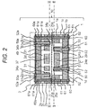
- FIG. 2 is a cross sectional view taken along line I-I in FIG. 1 .
- FIG. 3 is a plan view illustrating a II-II cross section of FIG. 2 .
- FIG. 4 is a plan view illustrating a III-III cross section of FIG. 2 .
- FIG. 5 illustrates a modification of FIG. 2 .
- FIG. 6 is a principle diagram of acceleration signal detection.
- FIG. 7 is a principle diagram of an angular velocity detection signal.
- the sensor chip 10 is constituted with an acceleration detector 20 configured to detect acceleration in the y-axis direction and a detector 30 configured to detect an angular velocity about the z-axis.
- the acceleration detector 20 is formed in a first laminate 1
- the angular velocity detector 30 is formed in a second laminate 2.
- the first laminate 1 and the second laminate 2 are laminated as illustrated in FIG. 2 , and a signal of the acceleration detector 20 and a signal of the angular velocity detector 30 are extracted on a same side in order to facilitate connection to an external circuit to be described below.
- the first laminate 1 has a configuration including a first substrate 1a consisting of mono-crystalline silicon, a second substrate 1b consisting of mono-crystalline silicon in a similar manner, and an oxide film 1c, in which the first substrate 1a and the second substrate 1b are laminated so as to sandwich the oxide film 1c therebetween.
- the laminate 1 may also use a substrate obtained by first forming an insulating film serving as the oxide film 1c on a substrate of silicon and glass bonded with each other, or on a silicon substrate serving as the second substrate 1b, and then forming on an upper portion thereof a conductive film such as a polysilicon film serving as the first substrate 1a.
- the laminate 1 is processed by photolithography and deep reactive ion etching (DRIE), thereby forming the acceleration detector 20.
- DRIE deep reactive ion etching
- the acceleration detector 20 is formed on the first substrate 1a.
- the acceleration detector 20 includes a weight 21, fixed portions 23a, 23b, 23c, and 23d supported and fixed to the second substrate 1b via the oxide film 1c, and beams 22a, 22b, 22c, and 22d joined to the fixed portions and movably supporting the weight 21 in a movable (Y) direction (described below).
- the weight 21 is suspended from the beam and a portion around the weight 21 is in a hollow state surrounded by cavity 29 in order to enable the weight 21 to be movable.
- electrodes 24a and 24b for forming capacitance with the weight 21, and electrodes 25a, 25b, and 26a for exchanging signals with an external circuit.
- the electrodes 25a, 25b, and 26a are configured such that the electrode 25a corresponds to the electrode 24a, the electrode 25b to the electrode 24b, and the electrode 26a to the weight 21.
- a penetrating electrode 50 is formed so as to penetrate the second substrate 1b, the oxide film 1c, and an insulating film 1d that insulates the electrode 52 described below.
- the penetrating electrode 50 is connected to the electrode 52.
- the outer periphery of the penetrating electrode 50 is covered with an insulating film 51 in order to electrically insulate from the substrate through which the penetrating electrode 50 penetrates.
- the inside of the penetrating electrode 50 is formed by embedding a conductive material such as polysilicon or metal.
- a penetrating electrode 60 penetrating the first substrate 1a, the second substrate 1b, the oxide film 1c, and the insulating film 1d, and connection to the electrode 62 is performed via the penetrating electrode 60.
- the outer periphery of the penetrating electrode 60 is covered with an insulating film 61, and the inside is formed of a conductive material such as polysilicon or metal.
- the mass of the weight 21 is defined, as m1 and the sum of spring constants of the beams 22a, 22b, 22c, and 22d in the movable (y) direction is defined as k 1 , as mainly illustrated in FIG. 3 .
- k 1 the sum of spring constants of the beams 22a, 22b, 22c, and 22d in the movable (y) direction.
- a distance between the weight 21 and each of the electrodes 24a and 24b varies, leading to a change in the capacitance of the weight 21 and the electrode 24a on the left side in a decreasing direction and leading to a change in the capacitance of the weight 21 and the electrode 24b on the right side in an increasing direction.
- the distance between the weight 21 and the electrode 24a on the left side increases, leading to a decrease in the capacitance, and at this time, the distance between the weight 21 and the electrode 24b on the right side decreases, leading to an increase in the capacitance.
- This change in the capacitance is output to and processed in the external integrated circuit 100.
- a carrier wave 101 for detecting the capacitance from the integrated circuit 100 formed on a semiconductor chip 3 is applied to the electrode 25a connected to the electrode 24a or to the electrode 25b connected to the electrode 24b, illustrated in FIG. 3 .
- This causes a capacitance change signal to be output from .the electrode 26a connected to the fixed portion 23a joined to the weight 21 illustrated in FIG. 3 via the beam 22a. That is, a signal of capacitance change from the acceleration detector 20 is input to a CV converter 102.
- the carrier wave 101 may be applied so as to have opposite phased waveforms between the electrode 25a and the electrode 25b.
- the signal of the capacitance change from the acceleration detector 20 can be input to the CV converter 102 by differential input. This makes it possible to increase the acceleration detection sensitivity.
- the capacitance change is converted into a voltage signal, and thereafter, the voltage signal is output to a synchronous detector 103.
- the synchronous detector 103 extracts solely a necessary signal component, and finally outputs an acceleration signal 104 in the form of voltage.
- the displacement amount y 1 of the weight 24 is proportional to the applied acceleration when the mass m 1 of the movable body and the total k 1 of the spring constants of the beams 22a, 22b, 22c, and 22d are constant. Accordingly, the applied acceleration can be detected by monitoring an output voltage (acceleration signal) proportional to the displacement amount y 1 .
- the acceleration sensor according to the first embodiment operates as described above.
- the acceleration in the x-axis direction is detected by arranging the acceleration detector 20 to be rotated by 90 degrees about the z-axis.
- an acceleration detector 20a adjacent to the acceleration detector 20 and rotated by 90 degrees about the z-axis with respect to the acceleration detector 20, it is possible to detect acceleration of two axes in the x-axis direction and the y-axis direction in the first laminate 1.
- the angular velocity detector 30 according to the present embodiment is formed by the second laminate 2, similarly to the first laminate 1.
- the angular velocity detector 30 is formed on a first substrate 2a constituting the second laminate 2.
- the angular velocity detector 30 includes: fixed portions 33a, 33b, 33c, and 33d supported and fixed to a second substrate 2b via an oxide film 2c; first beams 32a, 32b, 32c, and 32d respectively joined to the fixed portions and each movably supporting a first weight 31 described below; the first weight 31 suspended from the beams and movable in the movable (X) direction; and electrodes 34a and 34b configured to form capacitances with the weight 31 in order to drive the first weight 31.
- the angular velocity detector 30 further includes second beams 38a, 38b, 38c and 38d configured to join a second weight 37 to the first weight 31 and movably supporting the second weight 37 in a direction (Y) orthogonal to the first weight 31; the second weight 37 movable in the orthogonal (y) direction with respect to the first weight 31 by application of angular velocity; and electrodes 39a and 39b that form capacitance with the second weight 37 in order to detect a displacement amount of the second weight 37 at application of angular velocity as a change in capacitance.
- the angular velocity detector 30 further includes an electrode 35a for the electrode 34a, an electrode 35b for the electrode 34b, an electrode 36a for the second weight 37, an electrode 40a for the electrode 39a, and 40b for the electrode 39b.
- a penetrating electrode 50a that penetrates the second substrate 2b, the oxide film 2c, and an insulating film 2d for insulating the electrode 52a described below is formed, and the penetrating electrode 50a is connected to the electrode 52a.
- the outer periphery of the penetrating electrode 50a is covered with the insulating film 51a, and the inside is formed of a conductive material such as polysilicon or metal.
- the electrode 52a is extended in a planar direction, and similarly to the penetrating electrode 60 formed in the acceleration detector 20, a penetrating electrode 60a penetrating the first substrate 2a, the second substrate 2b, the oxide film 2c, and the insulating film 2d is formed and connected to the electrode 52a.
- the penetrating electrode 60a by arranging the penetrating electrode 60a at a position to be electrically connected to the penetrating electrode 60, the signal of the electrode 52a is connected to the electrode 62 arranged on the same side as the electrode 52.
- the outer periphery of the penetrating electrode 60a is covered with an insulating film 61a, and the inside is formed of a conductive material such as polysilicon or metal.
- an AC voltage of the frequency f is applied to the first electrodes 34a and 34b, so as to generate electrostatic force between the first weight 31 and the first electrodes 34a and 34b, thereby causing the first weight 31 to vibrate in the x-axis direction.
- the AC voltage is generated by an oscillator 205 provided, in an external integrated circuit 200.
- an amplifier 206 may be interposed, in order to obtain a predetermined voltage.
- the second weight 37 vibrates in the y-axis direction by the Coriolis force Fc expressed by Formula (6), and the capacitance between the second weight 37 and the second electrodes 39a and 39b changes. By detecting this capacitance change, it is possible to detect the angular velocity ⁇ about the z-axis.
- This change in the capacitance is output to and processed in the external integrated circuit 200.
- a carrier wave 201 for detecting the capacitance from the integrated circuit 200 formed on a semiconductor chip 3a is applied to the electrode 40a connected to the electrode 39a or to the electrode 40b connected to the electrode 39b, illustrated in FIG. 4 .
- the carrier wave 201 may be applied so as to have opposite phased waveforms between the electrode 40a and the electrode 40b.
- the signal of the capacitance change from the angular velocity detector 30 can be input to the CV converter 202 by differential input. This makes it possible to increase angular velocity detection sensitivity.
- the capacitance change is converted into a voltage signal, and thereafter, the voltage signal is output to a synchronous detector 203.
- the synchronous detector 203 extracts solely a necessary signal component and finally outputs an angular velocity signal 204 in the form of voltage.
- the voltage applied to the electrodes 39a and 39b may be servo-controlled such that the capacitance change between the weight 37 and the electrodes 39a, 39b, that is, the displacement amount in the y-axis direction of the weight 37 becomes zero, and the Coriolis force Fc may be obtained from the applied voltage.
- FIG. 8 it is possible to provide a structure in which two angular velocity detectors 30 are arranged side by side, and an angular velocity detector 30q1 on the left side and an angular velocity detector 30q2 on the right side are provided with being mutually connected via a third beam 41 formed on the first substrate 2a.
- the detection signal of the angular velocity can be detected with high sensitivity by obtaining a sum of a second weight 37q1 of the left side and a second weight 37q2 on the right side, leading to an advantage of capability of suppressing the vibration of a transducer from leaking to the outside.
- the angular velocity detector 30 formed in the second laminate 2 is the description of the angular velocity detector 30 formed in the second laminate 2 according to the present embodiment. Alternatively, however, it is allowable to form an acceleration detector 20b in the second laminate 2, similarly to the acceleration detector 20.
- the acceleration detector 20b may be arranged to be rotated by 90 degrees about the z-axis with respect to the acceleration detector 20, whereby the acceleration detector 20 detects the acceleration in the y-axis direction, while the acceleration detector 20b detects the acceleration about the x-axis, enabling the sensor chip 10 to be a biaxial acceleration sensor that detects acceleration in the x-axis and the y-axis directions.
- the acceleration detector 20b is arranged in the same direction as the acceleration detector 20, while by changing the dimensions of the beam and the weight, and the thickness of the first substrate 2a so as to change the spring constant k 1 and the mass m 1 expressed in Formula (7) to different values, it is possible to change the acceleration detection range.
- the sensor chip 10 can be a uniaxial acceleration sensor with a wider detection range without deteriorating detection accuracy.
- the first laminate 1 according to the present embodiment may include an angular velocity detector 30a similarly to the angular velocity detector 30.
- an angular velocity detector 30a similarly to the angular velocity detector 30.
- the integrated circuit 100 and the integrated circuit 200 are formed on the same semiconductor chip 3, it is possible to downsize the semiconductor chip.
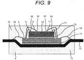
- the sensor chip 10 constituted as described above is assembled in a chip package 4 as illustrated in FIG. 9 .
- the sensor chip 10 is mounted on the semiconductor chip 3 via an adhesive 70 with an insulating film 2d side surface of the second laminate 2 facing the semiconductor chip 3, while the electrodes 52 and 62 of the sensor chip 10 are electrically connected to the semiconductor chip 3 via first wire bonding 71.
- the semiconductor chip 3 is mounted on a lead frame 72 via an adhesive 73, and the semiconductor chip 3 and the lead frame 72 are electrically connected via the second wire bonding 74. Then, these are sealed with resin 75, thereby forming the chip package 4.
- FIG. 10 illustrates as a chip package 4a as a modification of the chip package 4 illustrated in FIG. 9 .
- a semiconductor chip 3b includes electrodes 81 and 82 connected to the electrodes 52 and 62 on the sensor chip 10 at positions facing the electrodes 52 and 62, respectively. Portions between the electrodes 52 and 81 and between the electrodes 62 and 82 are electrically connected via a conductive material 76 such as a solder bump, thereby bonding the sensor chip 10 and the semiconductor chip 3b to each other.
- an adhesive 73a may be present in a portion where the conductive material 76 is absent in order to obtain adhesion reliability between the sensor chip 10 and the semiconductor chip 3b.
- the first wire bonding 71 can be omitted, and the height of the chip package 4a can be reduced.
- the wiring between the sensor chip 10 and the semiconductor chip 3 is shortened, making it possible to enhance sensor performance.
- a modification of the sensor chip 10 will be described as a second embodiment of the present invention.
- a sensor chip 10a is constituted with the acceleration detector 20 configured to detect acceleration in the y-axis direction and an acceleration detector 20c to be described below configured to detect acceleration in a direction (z-axis) orthogonal to the paper surface in FIG. 13 .
- the acceleration detector 20 configured to detect acceleration in the y-axis direction
- an acceleration detector 20c to be described below configured to detect acceleration in a direction (z-axis) orthogonal to the paper surface in FIG. 13 .
- FIG. 11 illustrates a modification of FIG. 2
- FIGS. 12 and 13 illustrate modifications of FIGS. 3 and 4
- the acceleration detector 20 is formed with the first laminate 1 similarly to the first embodiment.
- the acceleration detector 20c is formed with the second laminate 2, while an electrode 24ab forming capacitance with a weight 21b is formed at a position facing the weight 21b, in the first laminate 1.
- the acceleration detector 20c includes fixed portions 23ab, 23bb, 23cb, and 23db, and beams 22ab, 22bb, 22cb, and 22db, which are joined to the fixing portions respectively and support a weight 21b described below so as to be movable in the movable (Z) direction. Moreover, the acceleration detector 20c includes the weight 21b movable in the z-direction by application of acceleration, and also includes an electrode 24ab on the first substrate 1a of the first laminate as illustrated in FIG. 13 to form capacitance by facing the weight 21b in order to detect the displacement amount of the weight 21b as a change in capacitance.
- the acceleration detector 20c includes an electrode 25ab for exchanging signals with an external circuit, and similarly to the above description, the penetrating electrode 50 is connected to the electrode 25ab, while the electrode 52 is connected to the penetrating electrode 50 on the opposite side.
- the sensor chip 10a can detect acceleration in the y-axis direction and acceleration in the z-axis direction.
- an electrode 24bb may be formed on the second substrate 2b of the second laminate 2 on the side opposite to the weight 21b and the electrode 24ab, as illustrated in FIG. 14 , so as to generate a capacitance change in a direction opposite to the weight 21b and the electrode 24ab.
- an insulating portion 27 is provided around a side wall of the electrode 24bb.
- an electrode 25bb is provided on the opposite surface that does not face the weight 21b,of the electrode 24bb of the second substrate 2b. This configuration enables differential input to the CV converter 102, making it possible to increase the acceleration detection sensitivity.
- the acceleration detector 20 may be formed in the second laminate 2, and the electrode 24ab and the electrode 25ab may be formed in the second laminate 2 in the acceleration detector 20c, with the others formed in the first laminate 1.
- the angular velocity detector 30 may be formed instead of the acceleration detector 20. This enables formation of a sensor chip that detects the acceleration in the z-axis direction and the angular velocity about the z-axis.
- the electrode 24ab and the electrode 25ab may be formed in the second laminate 2, with other electrodes being formed in the first laminate in one acceleration detector 20c, while the electrode 24ab and the electrode 25ab may be formed in the first laminate 1 with other electrodes being formed in the second laminate 2 in the other acceleration detector 20c.
- a modification of the sensor chip 10 will be described as a third embodiment of the present invention.
- a sensor chip 10b is constituted with the acceleration detector 20 configured to detect acceleration in the y-axis direction and an acceleration detector 30b configured to detect angular velocity generated about the y-axis.
- the acceleration detector 20 configured to detect acceleration in the y-axis direction
- an acceleration detector 30b configured to detect angular velocity generated about the y-axis.
- FIG. 15 illustrates a modification of FIG. 2
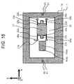
- FIGS. 16 and 17 illustrate modifications of FIGS. 3 and 4
- the acceleration detector 20 is formed of the first laminate 1 similarly to the first embodiment.
- the angular velocity detector 30b is formed with the second laminate 2, while an electrode 39ab forming capacitance with a weight 37b is formed at a position facing the weight 37b, in the first laminate 1.
- the angular velocity detector 30b includes second beams 38ab, 38bb, 38cb, and 38db that join the second weight 37b to the first weight 31, while supporting the second weight 37b with the first weight 31 in a movable state in the direction (z-axis) orthogonal to the paper surface.
- the angular velocity detector 30b includes the second weight 37b movable in the z-direction and also includes an electrode 39ab on the first substrate 1a of the first laminate 1 to form capacitance by facing the second weight 37b in order to detect the displacement amount of the second weight 37b in the z-direction at application of the angular velocity, as a change in capacitance.
- the angular velocity detector 30b includes an electrode 40ab for exchanging signals between the electrode 39ab and an external circuit, and similarly to the above description, the penetrating electrode 50 is connected to the electrode 40ab.
- the angular velocity detector 30b will be described focusing on a difference from the above-described operation of the angular velocity detector 30.
- the angular velocity ⁇ is applied about the y-axis in a state where the first weight 31 and the second weight 37b vibrate in the x-axis direction, and when the mass of the second weight 37b is m 22 , the Coriolis force Fc is generated in the z-axis direction as expressed by the above-described Formula (6). Then, the second weight 37b is displaced by the Coriolis force Fc in the z-axis direction.
- the second weight 37b vibrates in the z-axis direction by the Coriolis force Fc expressed by Formula (6), leading to a change in the capacitance between the second weight 37b and the second electrode 39ab.
- Fc Coriolis force
- the sensor chip 10b can detect acceleration in the y-axis direction and the angular velocity about the y-axis.
- the angular velocity about the x-axis is detected by arranging the angular velocity detector 30 to be rotated by 90 degrees about the z-axis.
- an electrode 39bb may be formed on the second substrate 2b opposite to the weight 37b and the electrode 39ab.
- the insulating portion 27 is provided around a side wall of the electrode 39bb.
- the electrode 25bb is provided on the opposite surface that does not face the weight 21b of the electrode 39bb.
- differential input can be performed to the CV converter 202, making it possible to increase the angular velocity detection sensitivity.
- the acceleration detector 20 may be formed in the second laminate 2, and the electrode 39ab and the electrode 40ab may be formed in the second laminate 2 in the angular velocity detector 30b, with the others formed in the first laminate 1.
- the angular velocity detector 30 may be formed instead of the acceleration detector 20. This enables formation of a sensor chip that detects the angular velocity about two axes, that is, about the z-axis and the y-axis.
- the electrode 39ab and the electrode 40ab may be formed in the second laminate 2, with other electrodes being formed in the first laminate 1 in one angular velocity detector 30b, while the electrode 39ab and the electrode 39ab may be formed in the first laminate 1 with other electrodes being -formed in the second laminate 2 in the other angular velocity detector 30b.
- one of the angular velocity detectors 30b is rotated by 90 degrees about the z-axis with respect to the other angular velocity detector 30b, it is possible to form a sensor chip that detects the angular velocity of each of two axes, that is, the y-axis and the x-axis.
- a sensor chip 10c is constituted with the acceleration detector 20 configured to detect acceleration, the angular velocity detector 30, and a pressure detector 300 that detects pressure.
- FIGS. 19 and 20 detailed descriptions of the same components as those in FIGS. 1 to 18 will be omitted, and different points will be mainly described.
- FIG. 19 illustrates a modification of FIG. 1
- FIG. 20 illustrates a modification of FIG. 2
- the acceleration detector 20 is formed of the first laminate 1 similarly to the first embodiment.
- the angular velocity detector 30 is formed with the second laminate 2.
- the pressure detector 300 is formed with a third laminate 301.
- the pressure detector 300 includes on the substrate 301a a deformable portion 302 that deforms in a direction perpendicular to a plane by applying pressure and includes a cavity 303 formed immediately below the deformable portion 302 in an oxide film 301c, or in the oxide film 301c and a portion of a substrate 301b.
- an electrode 304 is formed on the substrate 301b side opposed to the deformable portion 302 via the cavity 303. At this time, in order to insulate the electrode 304 from the other portion of the second substrate 301b, an insulating portion 305 is provided around a side wall of the electrode 304.
- the deformation of the deformable portion 302 may be configured to detect a change in piezoresistance of the deformable portion 302.
- P 0 and T are the following numerical values.
- the pressure detector 300 in the sensor chip 10c detects the pressure (about 0.1 MPa to 1 MPa) of a gas filled in a tire
- the rotation of the tire or the tire wheel can be detected by the acceleration detector 20 and the angular velocity detector 30, and at the same time, the pressure inside the tire can be detected by the pressure detector 300.
- each of the number of the first laminate. 1, the second laminate 2, and the third laminate may be two.
- the chip packages 4 and 4a may employ a resin substrate or ceramics instead of the lead frame 72 and may be formed as a ball grud array (BGA) package in which electrodes are extracted onto the back surface of the substrate by solder balls.
- BGA ball grud array
Landscapes
- Physics & Mathematics (AREA)
- General Physics & Mathematics (AREA)
- Engineering & Computer Science (AREA)
- Radar, Positioning & Navigation (AREA)
- Remote Sensing (AREA)
- Computer Hardware Design (AREA)
- Microelectronics & Electronic Packaging (AREA)
- Pressure Sensors (AREA)
- Gyroscopes (AREA)
- Micromachines (AREA)
Abstract
Description
- The present invention relates to an inertial force sensor, and more particularly to an acceleration sensor and an angular velocity sensor for measuring a motion state of a moving object such as a vehicle, an airplane, a robot, a mobile phone, a video camera.
- In recent years, inertial force sensors using microelectromechanical systems (MEMS) devices are being widely used for the purpose of preventing camera shake of a digital camera, attitude control of automobiles, robots, or the like.
- Generally, this type of inertial force sensor is formed by processing a semiconductor substrate such as silicon, a glass substrate, or the like, using an MEMS fabrication process such as etching, in which air-tightly sealed voids are formed by bonding the substrate with another substrate under constant atmosphere and pressure environment. For example,
PTL 1 describes an inertial force sensor including an acceleration detector and an angular velocity detector. - The acceleration detector includes a movable mechanical component that is a movable body formed with weights, beams, or the like. When the acceleration is applied, the movable body is displaced. Acceleration is detected by detecting a displacement amount of the movable body. In contrast, the angular velocity detector includes a movable mechanical component that is a vibrating body and applying angular velocity to a state in which the vibrating body drives at a certain frequency generates a Coriolis force. This Coriolis force causes the vibrating body to be displaced. The angular velocity is detected by detecting a displacement amount of the vibrating body by this Coriolis force.
- PTL 1:
JP 5298047 B2 - Meanwhile, in the above-described conventional technique, the acceleration detector and the angular velocity detector are installed on a same substrate. The acceleration detector and the angular velocity detector have mutually different performance requirements such as the detection sensitivity and the frequency response, and thus, the natural frequency, the electrode dimensions, or the like, for determining the structure of the detector are also different from each other. For example,' a natural frequency f is expressed by a relationship between a mass m of a weight and a spring constant k of a beam as expressed in Formula (1)
[Mathematical Formula 1]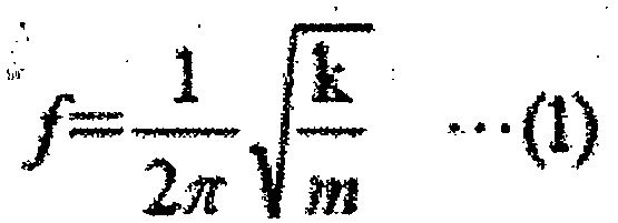
- Herein, the mass m of the weight is expressed by Formula (2), while the spring constant k is expressed by Formula (3)
[Mathematical Formula 2]
- In Formula (2), S, h, and ρ are the following numerical values.
- S: area (area of the weight as viewed from the substrate surface)
- h: substrate thickness (thickness of the weight as viewed from the substrate front surface)
- ρ: density (density of a material constituting the substrate)
- In Formula (3), α, w, l, and E are the following numerical values.
- α: a constant
- w: beam width (width of the beam viewed from the substrate front surface)
- l: length of beam
- E: Young's modulus
- From Formulas (1), (2) and (3), the natural frequency f is expressed by Formula (4).
[Mathematical Formula 4]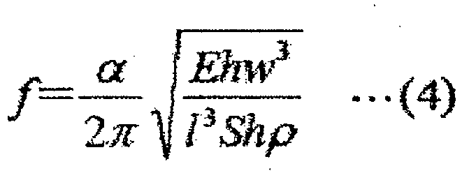
- In the, composite sensor, however, a natural frequency f1 of the acceleration detector is about 1 kHz to 3 kHz, while a natural frequency f2 of the angular velocity detector is about 15 kHz to 25 kHz, leading to a difference between them in some cases.
- For example, when the angular velocity detector and the acceleration detector are formed on a same substrate, a thickness h of the substrate is common to the two detectors. Moreover, from a viewpoint of the MEMS fabrication process described above, variation in fabricated shapes can be more equalized by also using a common beam width w. Accordingly, in order to obtain the mutually different natural frequencies f1 and f2, the area S and the
length 1 of the beam are to be individually changed. - In the angular velocity detector, however, a Coriolis force Fc generated at application of the angular velocity has relationships illustrated in Formulas (5) and (6) with respect to an angular velocity Ω. Therefore, in order to increase the Coriolis force, it is preferable to increase the mass of the weight m22, and thus, it is difficult to reduce the mass of the weight m2 in order to make the natural frequency f2 higher than the natural frequency f1.
[Mathematical Formula 5]
- In Formula (5), m21 and m22 are the following numerical values.
- m21: mass of a movable portion non-reacting to the angular velocity Ω in the weight m2
- m22: mass of the movable portion reacting to the angular velocity Ω in the weight m2
- In Formula (6), v is the following numerical value.
v: velocity at drive of weight m2 - In order to solve the above-described problem, it is effective to configure such that an inertial force sensor according to the present invention includes a layer in which a detector is formed and that the layer has a laminated structure in which two or more layers are laminated. With this configuration, the thickness h can be set to an arbitrary thickness in each of the detectors.
- In order to achieve the above-described object, effects obtained by representative ones of the inventions disclosed in the present application will be briefly described as follows.
- According to
claim 1 of the present invention, an inertial force sensor includes a layer in which a detector is formed, and the layer is a laminated structure in which two or more layers are laminated. According to the present invention, since the detectors are formed in lamination, it is possible to achieve downsizing compared with a sensor in which detectors are arranged on a plane. - According to claim 4 of the invention, the inertial force sensor is characterized in that at least one pair of detectors is arranged such that the movable body and the electrode are formed in mutually different layers. According to the present invention, in a case where the movable body moves in a direction perpendicular to a plane and this movement is to be detected, the electrode is installed at a position facing the plane of the movable body, that is, in another layer. In this case, as described in
claim 5 of the invention, the detector in which the movable body and the electrode are formed in mutually different layers is configured such that the electrode is formed in a same layer in which the movable body of another detector is formed. This makes it possible to reduce the height of the sensor chip because there is no need to provide another layer for the electrode. - According to claim 6 of the invention, the inertial force sensor is characterized to include two sets of the at least one pair of detectors being arranged in an array. According to the present invention, for example, by arranging, in the array, the individual detectors in a direction orthogonal to each other on a plane, it is possible to detect an inertial force in the two-dimensional direction. On the other hand, for example, by arranging the individual detectors in a same direction on the plane in the array, it is possible to detect a positional deviation between the individual detectors, detect warping and bending occurring in the sensor chip forming the array, and by correcting the warping and bending by an external circuit, it is possible to enhance detection accuracy of the sensor.
-
-
FIG. 1 is an overall view of asensor chip 10 according to a first embodiment of the present invention. -
FIG. 2 is a cross-sectional view taken along line I-I inFIG. 1 . -
FIG. 3 is a plan view illustrating a II-II cross section ofFIG. 2 . -
FIG. 4 is a plan view illustrating a III-III cross section ofFIG. 2 . -
FIG. 5 is a modification ofFIG. 3 . -
FIG. 6 is a principle diagram of acceleration signal detection. -
Fig. 7 is a principle diagram of angular velocity signal detection -
FIG. 8 is modification ofFIG. 4 . -
FIG. 9 is a cross-sectional view of a chip package 4 according to the first embodiment of the present invention. -
FIG. 10 is a modification ofFIG. 9 . -
FIG. 11 is a cross-sectional view of asensor chip 10a according to a second embodiment of the present invention. -
FIG. 12 is a plan view illustrating a IV-IV cross section ofFIG. 11 . -
FIG. 13 is a plan view illustrating a V-V cross section ofFIG. 11 . -
FIG. 14 is a modification ofFIG. 11 . -
FIG. 15 is a cross-sectional view of asensor chip 10b according to a third embodiment of the present invention. -
FIG. 16 is a plan view illustrating a VI-VI cross section ofFIG. 15 . -
FIG. 17 is a plan view illustrating a VII-VII cross section ofFIG. 15 . -
FIG. 18 is a modification ofFIG. 15 . -
FIG. 19 is an overall view of asensor chip 10c according to a fourth embodiment of the present invention. -
FIG. 20 is a cross sectional view take along line VIII-VIII inFIG. 19 . - The following embodiments will be described by being divided into a plurality of sections or embodiments as needed for the sake of convenience. However, unless otherwise stated, the plurality of sections or embodiments is not irrelevant to each other, but rather in a relationship of one being a modification, elaboration, supplementary explanation, or the like, of a portion or all of another one.
- In addition, when the number or the like of the components (including a number, a numerical value, an amount, a range) is referred to in the following embodiments, the number is not limited to a particular number but rather may be a number equal to or more/less than the particular number, except for the cases where explicitly stated, apparently limited to the particular number in principle, or the like.
- Furthermore, components (including element steps, or the like) in the following embodiment are not necessarily indispensable, except for the cases where explicitly stated, considered apparently indispensable in principle, or the like.
- In a similar manner, when a shape, a positional relationship, or the like, of the components, or the like, is referred to in the following embodiment, it is assumed that the shape, or the like, includes a shape substantially approximate or similar thereto, except for the cases where clearly explicitly state, apparently not conceivable in principle, or the like. This also applies to the above-described numerical values and ranges in a similar manner.
- In all the drawings for illustrating the embodiments, identical members are denoted by same reference symbols in principle, and duplicated description thereof will be omitted. Even in a plan view, hatching are added to make the drawing more understandable.
- In the present embodiment, the invention will be described using a sensor chip for detecting acceleration and angular velocity.
FIG. 1 is an overall view of asensor chip 10 according to a first embodiment of the present invention.FIG. 2 is a cross sectional view taken along line I-I inFIG. 1 .FIG. 3 is a plan view illustrating a II-II cross section ofFIG. 2 .FIG. 4 is a plan view illustrating a III-III cross section ofFIG. 2 .FIG. 5 illustrates a modification ofFIG. 2 .FIG. 6 is a principle diagram of acceleration signal detection.FIG. 7 is a principle diagram of an angular velocity detection signal. - In the present embodiment, the
sensor chip 10 is constituted with anacceleration detector 20 configured to detect acceleration in the y-axis direction and adetector 30 configured to detect an angular velocity about the z-axis. In thesensor chip 10, theacceleration detector 20 is formed in afirst laminate 1, and theangular velocity detector 30 is formed in asecond laminate 2. Thefirst laminate 1 and thesecond laminate 2 are laminated as illustrated inFIG. 2 , and a signal of theacceleration detector 20 and a signal of theangular velocity detector 30 are extracted on a same side in order to facilitate connection to an external circuit to be described below. - First, the
first laminate 1 and theacceleration detector 20 will be described. - The
first laminate 1 has a configuration including afirst substrate 1a consisting of mono-crystalline silicon, asecond substrate 1b consisting of mono-crystalline silicon in a similar manner, and anoxide film 1c, in which thefirst substrate 1a and thesecond substrate 1b are laminated so as to sandwich theoxide film 1c therebetween. Alternatively, thelaminate 1 may also use a substrate obtained by first forming an insulating film serving as theoxide film 1c on a substrate of silicon and glass bonded with each other, or on a silicon substrate serving as thesecond substrate 1b, and then forming on an upper portion thereof a conductive film such as a polysilicon film serving as thefirst substrate 1a. - Then, the
laminate 1 is processed by photolithography and deep reactive ion etching (DRIE), thereby forming theacceleration detector 20. - As illustrated in
FIG. 3 , theacceleration detector 20 is formed on thefirst substrate 1a. Theacceleration detector 20 includes aweight 21, fixedportions second substrate 1b via theoxide film 1c, andbeams weight 21 in a movable (Y) direction (described below). At this time, theweight 21 is suspended from the beam and a portion around theweight 21 is in a hollow state surrounded bycavity 29 in order to enable theweight 21 to be movable. - For detecting the
movable weight 21 and detecting a displacement amount of theweight 21 by application of acceleration as a change in capacitance, there provided areelectrodes weight 21, andelectrodes electrodes electrode 25a corresponds to theelectrode 24a, theelectrode 25b to theelectrode 24b, and theelectrode 26a to theweight 21. - In order to connect the
electrodes FIG. 2 , a penetratingelectrode 50 is formed so as to penetrate thesecond substrate 1b, theoxide film 1c, and an insulatingfilm 1d that insulates theelectrode 52 described below. The penetratingelectrode 50 is connected to theelectrode 52. - In the penetrating
electrode 50, the outer periphery of the penetratingelectrode 50 is covered with an insulatingfilm 51 in order to electrically insulate from the substrate through which the penetratingelectrode 50 penetrates. On the other hand, the inside of the penetratingelectrode 50 is formed by embedding a conductive material such as polysilicon or metal. - Furthermore, in order to connect the electrodes constituting the
angular velocity detector 30 described below on the same side as the external circuit, there provided is a penetratingelectrode 60 penetrating thefirst substrate 1a, thesecond substrate 1b, theoxide film 1c, and the insulatingfilm 1d, and connection to theelectrode 62 is performed via the penetratingelectrode 60. Similarly to the penetratingelectrode 50, the outer periphery of the penetratingelectrode 60 is covered with an insulatingfilm 61, and the inside is formed of a conductive material such as polysilicon or metal. - Subsequently, operation of the acceleration detector'20 according to the first embodiment will be described. In the first embodiment, the mass of the
weight 21 is defined, as m1 and the sum of spring constants of thebeams FIG. 3 . At this time, when a force F1 is generated in theweight 21 in a case where acceleration a1 is applied in the movable (y) direction of theweight 21, theweight 21 is displaced in the movable (y) direction, leading to generation of a displacement amount y1. This relationship is expressed by Formula (7).
[Mathematical Formula 7]
- When the displacement y1 is generated, a distance between the
weight 21 and each of theelectrodes weight 21 and theelectrode 24a on the left side in a decreasing direction and leading to a change in the capacitance of theweight 21 and theelectrode 24b on the right side in an increasing direction. For example, in a case where theweight 21 is displaced in the right direction inFIG. 3 , the distance between theweight 21 and theelectrode 24a on the left side increases, leading to a decrease in the capacitance, and at this time, the distance between theweight 21 and theelectrode 24b on the right side decreases, leading to an increase in the capacitance. - This change in the capacitance is output to and processed in the external
integrated circuit 100. - Specifically, as illustrated in
FIG. 6 , acarrier wave 101 for detecting the capacitance from theintegrated circuit 100 formed on asemiconductor chip 3 is applied to theelectrode 25a connected to theelectrode 24a or to theelectrode 25b connected to theelectrode 24b, illustrated inFIG. 3 . This causes a capacitance change signal to be output from .theelectrode 26a connected to the fixedportion 23a joined to theweight 21 illustrated inFIG. 3 via thebeam 22a. That is, a signal of capacitance change from theacceleration detector 20 is input to aCV converter 102. At this time, as illustrated inFIG. 6 , thecarrier wave 101 may be applied so as to have opposite phased waveforms between theelectrode 25a and theelectrode 25b. In this case, the signal of the capacitance change from theacceleration detector 20 can be input to theCV converter 102 by differential input. This makes it possible to increase the acceleration detection sensitivity. - In the
CV converter 102, the capacitance change is converted into a voltage signal, and thereafter, the voltage signal is output to asynchronous detector 103. Thesynchronous detector 103 extracts solely a necessary signal component, and finally outputs anacceleration signal 104 in the form of voltage. At this time, the displacement amount y1 of the weight 24 is proportional to the applied acceleration when the mass m1 of the movable body and the total k1 of the spring constants of thebeams - The above is an explanation of the
acceleration detector 20 formed in thefirst laminate 1 according to the present embodiment. In this, for example, the acceleration in the x-axis direction is detected by arranging theacceleration detector 20 to be rotated by 90 degrees about the z-axis. - Furthermore, as illustrated in
FIG. 5 , by forming, in thefirst laminate 1, anacceleration detector 20a adjacent to theacceleration detector 20 and rotated by 90 degrees about the z-axis with respect to theacceleration detector 20, it is possible to detect acceleration of two axes in the x-axis direction and the y-axis direction in thefirst laminate 1. - Next, the
second laminate 2 and theangular velocity detector 30 will be described. - The
angular velocity detector 30 according to the present embodiment is formed by thesecond laminate 2, similarly to thefirst laminate 1. - As illustrated in
FIG. 4 , theangular velocity detector 30 is formed on afirst substrate 2a constituting thesecond laminate 2. Theangular velocity detector 30 includes: fixedportions second substrate 2b via anoxide film 2c;first beams first weight 31 described below; thefirst weight 31 suspended from the beams and movable in the movable (X) direction; andelectrodes weight 31 in order to drive thefirst weight 31. - The
angular velocity detector 30 further includessecond beams second weight 37 to thefirst weight 31 and movably supporting thesecond weight 37 in a direction (Y) orthogonal to thefirst weight 31; thesecond weight 37 movable in the orthogonal (y) direction with respect to thefirst weight 31 by application of angular velocity; andelectrodes second weight 37 in order to detect a displacement amount of thesecond weight 37 at application of angular velocity as a change in capacitance. - Moreover, as electrodes for exchanging signals with an external circuit, the
angular velocity detector 30 further includes anelectrode 35a for theelectrode 34a, anelectrode 35b for theelectrode 34b, anelectrode 36a for thesecond weight 37, anelectrode 40a for theelectrode electrode 39b. - In order to connect the
electrodes laminate 2. Here, first, similarly to theacceleration detector 20, a penetratingelectrode 50a that penetrates thesecond substrate 2b, theoxide film 2c, and an insulatingfilm 2d for insulating theelectrode 52a described below is formed, and the penetratingelectrode 50a is connected to theelectrode 52a. Similarly to the penetratingelectrode 50, the outer periphery of the penetratingelectrode 50a is covered with the insulatingfilm 51a, and the inside is formed of a conductive material such as polysilicon or metal. - Furthermore, in order to extract the
electrode 52a to the same side as theelectrode 52 formed in thefirst laminate 1, theelectrode 52a is extended in a planar direction, and similarly to the penetratingelectrode 60 formed in theacceleration detector 20, a penetratingelectrode 60a penetrating thefirst substrate 2a, thesecond substrate 2b, theoxide film 2c, and the insulatingfilm 2d is formed and connected to theelectrode 52a. At this time, by arranging the penetratingelectrode 60a at a position to be electrically connected to the penetratingelectrode 60, the signal of theelectrode 52a is connected to theelectrode 62 arranged on the same side as theelectrode 52. Similarly to the penetratingelectrode 60, the outer periphery of the penetratingelectrode 60a is covered with an insulatingfilm 61a, and the inside is formed of a conductive material such as polysilicon or metal. - Subsequently, operation of the
angular velocity detector 30 according to the first embodiment will be described. - First, in order to bring the
first weight 31 into a state of vibrating with a constant frequency f and a constant amplitude Xe in the x-axis direction, an AC voltage of the frequency f is applied to thefirst electrodes first weight 31 and thefirst electrodes first weight 31 to vibrate in the x-axis direction. The AC voltage is generated by anoscillator 205 provided, in an externalintegrated circuit 200. In theoscillator 205, anamplifier 206 may be interposed, in order to obtain a predetermined voltage. - In a state where the
first weight 31 vibrates in the x-axis direction, theweight 37 as the second vibrating body vibrates in conjunction with thefirst weight 31 in the x-axis direction. At this time, the relationship between a displacement x in the x-axis direction of thefirst weight 31 and a velocity v thereof is expressed by Formula (8).
[Mathematical Formula 8]

- In Formula (8), f, Xe, and t are the following numerical values.
- f: frequency
- Xe: amplitude
- t: time
- In a case where the angular velocity Ω is applied about the z-axis orthogonal to the paper surface of
FIG. 4 in a state where thefirst weight 31 and thesecond weight 37 vibrate in the x-axis direction as described above, and when the mass of thesecond weight 37 is m22, the Coriolis force Fc is generated in the y-axis direction as expressed by the above-described Formula (6). Then, thesecond weight 37 is displaced by the Coriolis force Fc in the y-axis direction. - The
second weight 37 vibrates in the y-axis direction by the Coriolis force Fc expressed by Formula (6), and the capacitance between thesecond weight 37 and thesecond electrodes - This change in the capacitance is output to and processed in the external
integrated circuit 200. - Specifically, as illustrated in
FIG. 7 , a carrier wave 201 for detecting the capacitance from theintegrated circuit 200 formed on a semiconductor chip 3a is applied to theelectrode 40a connected to theelectrode 39a or to theelectrode 40b connected to theelectrode 39b, illustrated inFIG. 4 . - This causes the signal of the
second weight 37 illustrated inFIG. 7 to be connected to thefirst weight 31 via thesecond beams electrode 36a connected to the fixedportion 33a via thefirst beam 32a. That is, the capacitance change signal from theelectrode 36a is input to aCV converter 202 of theintegrated circuit 200. - At this time, as illustrated in
FIG. 7 , the carrier wave 201 may be applied so as to have opposite phased waveforms between theelectrode 40a and theelectrode 40b. In this case, the signal of the capacitance change from theangular velocity detector 30 can be input to theCV converter 202 by differential input. This makes it possible to increase angular velocity detection sensitivity. - In the
CV converter 202, the capacitance change is converted into a voltage signal, and thereafter, the voltage signal is output to asynchronous detector 203. Thesynchronous detector 203 extracts solely a necessary signal component and finally outputs anangular velocity signal 204 in the form of voltage. - As a method of measuring the displacement amount of the
weight 37 that is the second vibrating body, the voltage applied to theelectrodes weight 37 and theelectrodes weight 37 becomes zero, and the Coriolis force Fc may be obtained from the applied voltage. - Moreover, as a modification of
FIG. 4 , as illustrated inFIG. 8 , it is possible to provide a structure in which twoangular velocity detectors 30 are arranged side by side, and an angular velocity detector 30q1 on the left side and an angular velocity detector 30q2 on the right side are provided with being mutually connected via athird beam 41 formed on thefirst substrate 2a. Then, by oscillating the first weight 31q1 on the left side and the first weight 31q2 on the right side in opposite phases, acceleration from the outside can be canceled out or counter balanced, and while doing this, the detection signal of the angular velocity can be detected with high sensitivity by obtaining a sum of a second weight 37q1 of the left side and a second weight 37q2 on the right side, leading to an advantage of capability of suppressing the vibration of a transducer from leaking to the outside. - The above is the description of the
angular velocity detector 30 formed in thesecond laminate 2 according to the present embodiment. Alternatively, however, it is allowable to form an acceleration detector 20b in thesecond laminate 2, similarly to theacceleration detector 20. - At this time, the acceleration detector 20b may be arranged to be rotated by 90 degrees about the z-axis with respect to the
acceleration detector 20, whereby theacceleration detector 20 detects the acceleration in the y-axis direction, while the acceleration detector 20b detects the acceleration about the x-axis, enabling thesensor chip 10 to be a biaxial acceleration sensor that detects acceleration in the x-axis and the y-axis directions. - In addition, the acceleration detector 20b is arranged in the same direction as the
acceleration detector 20, while by changing the dimensions of the beam and the weight, and the thickness of thefirst substrate 2a so as to change the spring constant k1 and the mass m1 expressed in Formula (7) to different values, it is possible to change the acceleration detection range. As a result,' thesensor chip 10 can be a uniaxial acceleration sensor with a wider detection range without deteriorating detection accuracy. - Furthermore, the
first laminate 1 according to the present embodiment may include an angular velocity detector 30a similarly to theangular velocity detector 30. At this time, by changing the dimensions of the beam and the weight, and the thickness of thefirst substrate 1a, so as to change the frequency f and the mass m2 of the weight expressed in Formulas (8) and (9) to different values, it is possible to change the detection range of the angular velocity, enabling thesensor chip 10 to be a uniaxial angular velocity sensor with a wider detection range without deteriorating detection accuracy. - Moreover, by forming the
integrated circuit 100 and theintegrated circuit 200 on thesame semiconductor chip 3, it is possible to downsize the semiconductor chip. - The
sensor chip 10 constituted as described above is assembled in a chip package 4 as illustrated inFIG. 9 . Thesensor chip 10 is mounted on thesemiconductor chip 3 via an adhesive 70 with an insulatingfilm 2d side surface of thesecond laminate 2 facing thesemiconductor chip 3, while theelectrodes sensor chip 10 are electrically connected to thesemiconductor chip 3 viafirst wire bonding 71. Thesemiconductor chip 3 is mounted on alead frame 72 via an adhesive 73, and thesemiconductor chip 3 and thelead frame 72 are electrically connected via thesecond wire bonding 74. Then, these are sealed withresin 75, thereby forming the chip package 4. - Furthermore,
FIG. 10 illustrates as achip package 4a as a modification of the chip package 4 illustrated inFIG. 9 . InFIG. 10 , asemiconductor chip 3b includeselectrodes electrodes sensor chip 10 at positions facing theelectrodes electrodes electrodes conductive material 76 such as a solder bump, thereby bonding thesensor chip 10 and thesemiconductor chip 3b to each other. At this time, an adhesive 73a may be present in a portion where theconductive material 76 is absent in order to obtain adhesion reliability between thesensor chip 10 and thesemiconductor chip 3b. With the structure illustrated inFIG. 10 , thefirst wire bonding 71 can be omitted, and the height of thechip package 4a can be reduced. In addition, the wiring between thesensor chip 10 and thesemiconductor chip 3 is shortened, making it possible to enhance sensor performance. - A modification of the
sensor chip 10 will be described as a second embodiment of the present invention. - In the present embodiment, a
sensor chip 10a is constituted with theacceleration detector 20 configured to detect acceleration in the y-axis direction and an acceleration detector 20c to be described below configured to detect acceleration in a direction (z-axis) orthogonal to the paper surface inFIG. 13 . Hereinafter, in explanation ofFIGS. 11 ,12 ,13 , and14 , detailed descriptions of the same components as those inFIGS. 1 to 10 will be omitted, and different points will be mainly described. -
FIG. 11 illustrates a modification ofFIG. 2 , andFIGS. 12 and13 illustrate modifications ofFIGS. 3 and4 . In thesensor chip 10a, theacceleration detector 20 is formed with thefirst laminate 1 similarly to the first embodiment. In contrast, the acceleration detector 20c is formed with thesecond laminate 2, while an electrode 24ab forming capacitance with aweight 21b is formed at a position facing theweight 21b, in thefirst laminate 1. - The acceleration detector 20c includes fixed portions 23ab, 23bb, 23cb, and 23db, and beams 22ab, 22bb, 22cb, and 22db, which are joined to the fixing portions respectively and support a
weight 21b described below so as to be movable in the movable (Z) direction. Moreover, the acceleration detector 20c includes theweight 21b movable in the z-direction by application of acceleration, and also includes an electrode 24ab on thefirst substrate 1a of the first laminate as illustrated inFIG. 13 to form capacitance by facing theweight 21b in order to detect the displacement amount of theweight 21b as a change in capacitance. The acceleration detector 20c includes an electrode 25ab for exchanging signals with an external circuit, and similarly to the above description, the penetratingelectrode 50 is connected to the electrode 25ab, while theelectrode 52 is connected to the penetratingelectrode 50 on the opposite side. - As described above, the
sensor chip 10a can detect acceleration in the y-axis direction and acceleration in the z-axis direction. - Alternatively, in the present embodiment, as illustrated in
FIG. 6 , in order to perform differential input of.the capacitance formed by facing theweight 21b into theCV converter 102, an electrode 24bb may be formed on thesecond substrate 2b of thesecond laminate 2 on the side opposite to theweight 21b and the electrode 24ab, as illustrated inFIG. 14 , so as to generate a capacitance change in a direction opposite to theweight 21b and the electrode 24ab. At this time, in order to insulate the electrode 24bb from the other portion of thesecond substrate 2b, an insulatingportion 27 is provided around a side wall of the electrode 24bb. In order to exchange signals with an external circuit, an electrode 25bb is provided on the opposite surface that does not face theweight 21b,of the electrode 24bb of thesecond substrate 2b. This configuration enables differential input to theCV converter 102, making it possible to increase the acceleration detection sensitivity. - Alternatively, in the present embodiment, the
acceleration detector 20 may be formed in thesecond laminate 2, and the electrode 24ab and the electrode 25ab may be formed in thesecond laminate 2 in the acceleration detector 20c, with the others formed in thefirst laminate 1. - Furthermore, as a modification of the present embodiment, the
angular velocity detector 30 may be formed instead of theacceleration detector 20. This enables formation of a sensor chip that detects the acceleration in the z-axis direction and the angular velocity about the z-axis. - Moreover, as a modification of the present embodiment, it is also allowable to provide a plurality of acceleration detectors 20c. In this case, the electrode 24ab and the electrode 25ab may be formed in the
second laminate 2, with other electrodes being formed in the first laminate in one acceleration detector 20c, while the electrode 24ab and the electrode 25ab may be formed in thefirst laminate 1 with other electrodes being formed in thesecond laminate 2 in the other acceleration detector 20c. Then, by changing the dimensions of the beam and the weight, the thicknesses of thefirst substrates - A modification of the
sensor chip 10 will be described as a third embodiment of the present invention. - In the present embodiment, a
sensor chip 10b is constituted with theacceleration detector 20 configured to detect acceleration in the y-axis direction and an acceleration detector 30b configured to detect angular velocity generated about the y-axis. Hereinafter, in explanation ofFIGS. 15 ,16 ,17 , and18 , detailed descriptions of the same components as those inFIGS. 1 to 14 will be omitted, and different points will be mainly described. -
FIG. 15 illustrates a modification ofFIG. 2 , andFIGS. 16 and17 illustrate modifications ofFIGS. 3 and4 . As illustrated inFIG. 15 , in thepresent sensor chip 10b, theacceleration detector 20 is formed of thefirst laminate 1 similarly to the first embodiment. In contrast, the angular velocity detector 30b is formed with thesecond laminate 2, while an electrode 39ab forming capacitance with aweight 37b is formed at a position facing theweight 37b, in thefirst laminate 1. - As illustrated in
FIG. 17 , the angular velocity detector 30b includes second beams 38ab, 38bb, 38cb, and 38db that join thesecond weight 37b to thefirst weight 31, while supporting thesecond weight 37b with thefirst weight 31 in a movable state in the direction (z-axis) orthogonal to the paper surface. Moreover, the angular velocity detector 30b includes thesecond weight 37b movable in the z-direction and also includes an electrode 39ab on thefirst substrate 1a of thefirst laminate 1 to form capacitance by facing thesecond weight 37b in order to detect the displacement amount of thesecond weight 37b in the z-direction at application of the angular velocity, as a change in capacitance. The angular velocity detector 30b includes an electrode 40ab for exchanging signals between the electrode 39ab and an external circuit, and similarly to the above description, the penetratingelectrode 50 is connected to the electrode 40ab. - Next, operation of the angular velocity detector 30b will be described focusing on a difference from the above-described operation of the
angular velocity detector 30. In a case where the angular velocity Ω is applied about the y-axis in a state where thefirst weight 31 and thesecond weight 37b vibrate in the x-axis direction, and when the mass of thesecond weight 37b is m22, the Coriolis force Fc is generated in the z-axis direction as expressed by the above-described Formula (6). Then, thesecond weight 37b is displaced by the Coriolis force Fc in the z-axis direction. - The
second weight 37b vibrates in the z-axis direction by the Coriolis force Fc expressed by Formula (6), leading to a change in the capacitance between thesecond weight 37b and the second electrode 39ab. By detecting this capacitance change, it is possible to detect the angular velocity Ω about the y-axis. - As described above, the
sensor chip 10b can detect acceleration in the y-axis direction and the angular velocity about the y-axis. - As a modification of the present embodiment, for example, the angular velocity about the x-axis is detected by arranging the
angular velocity detector 30 to be rotated by 90 degrees about the z-axis. - Alternatively, in the present embodiment, as illustrated in
FIG. 18 , it is allowable to configure to generate a capacitance change in a direction opposite to theweight 37b and the electrode 39ab in order to perform differential input of the capacitance formed by facing theweight 37b into theCV converter 202. In this case, for example, as illustrated inFIG. 18 , an electrode 39bb may be formed on thesecond substrate 2b opposite to theweight 37b and the electrode 39ab. At this time, in order to insulate the electrode 39bb from the other portion of thesecond substrate 2b, the insulatingportion 27 is provided around a side wall of the electrode 39bb. In order to exchange signals with an external circuit, the electrode 25bb is provided on the opposite surface that does not face theweight 21b of the electrode 39bb. As described above, differential input can be performed to theCV converter 202, making it possible to increase the angular velocity detection sensitivity. - Alternatively, as a modification of the present embodiment, the
acceleration detector 20 may be formed in thesecond laminate 2, and the electrode 39ab and the electrode 40ab may be formed in thesecond laminate 2 in the angular velocity detector 30b, with the others formed in thefirst laminate 1. - Moreover, as a modification of the present embodiment, the
angular velocity detector 30 may be formed instead of theacceleration detector 20. This enables formation of a sensor chip that detects the angular velocity about two axes, that is, about the z-axis and the y-axis. - Moreover, as a modification of the present embodiment, it is also allowable to provide a plurality of angular velocity detectors 30b. In this case, the electrode 39ab and the electrode 40ab may be formed in the
second laminate 2, with other electrodes being formed in thefirst laminate 1 in one angular velocity detector 30b, while the electrode 39ab and the electrode 39ab may be formed in thefirst laminate 1 with other electrodes being -formed in thesecond laminate 2 in the other angular velocity detector 30b. - At this time, by changing the dimensions of the beam and the weight, and the thickness of the
first substrate 1a, so as to change the frequency f and the mass m2 of the weight expressed in Formulas (8) and (9) to different values, it is possible to change the detection range of the angular velocity, enabling thesensor chip 10b to be a uniaxial angular velocity sensor with a wider detection range without deteriorating detection accuracy. - . Alternatively, by arranging one of the angular velocity detectors 30b to be rotated by 90 degrees about the z-axis with respect to the other angular velocity detector 30b, it is possible to form a sensor chip that detects the angular velocity of each of two axes, that is, the y-axis and the x-axis.
- A modification of the
sensor chip 10 will be described as a fourth embodiment of the present invention. In the present embodiment, asensor chip 10c is constituted with theacceleration detector 20 configured to detect acceleration, theangular velocity detector 30, and apressure detector 300 that detects pressure. - Hereinafter, in explanation of
FIGS. 19 and20 , detailed descriptions of the same components as those inFIGS. 1 to 18 will be omitted, and different points will be mainly described. -
FIG. 19 illustrates a modification ofFIG. 1 , andFIG. 20 illustrates a modification ofFIG. 2 . In thesensor chip 10c, theacceleration detector 20 is formed of thefirst laminate 1 similarly to the first embodiment. In contrast, theangular velocity detector 30 is formed with thesecond laminate 2. Thepressure detector 300 is formed with athird laminate 301. - The
pressure detector 300 includes on thesubstrate 301a adeformable portion 302 that deforms in a direction perpendicular to a plane by applying pressure and includes acavity 303 formed immediately below thedeformable portion 302 in anoxide film 301c, or in theoxide film 301c and a portion of asubstrate 301b. - Note that in a case where deformation of the
deformable portion 302 is detected by the capacitance of the cavity, anelectrode 304 is formed on thesubstrate 301b side opposed to thedeformable portion 302 via thecavity 303. At this time, in order to insulate theelectrode 304 from the other portion of thesecond substrate 301b, an insulatingportion 305 is provided around a side wall of theelectrode 304. - On the other hand, the deformation of the
deformable portion 302 may be configured to detect a change in piezoresistance of thedeformable portion 302. - Moreover, by eliminating the
resin 75 immediately above thedeformable portion 302 in a chip package of thesensor chip 10c, it is possible to enhance pressure detection accuracy. - In the
above sensor chip 10c, for example, in a case where thepressure detector 300 detects the vicinity of the atmospheric pressure (0.1 MPa) and includes a temperature measuring function on thesemiconductor chip 3, or the like, an atmospheric pressure P at this time can be converted into an altitude H as expressed in Formula (9). This enables highly accurate detection of the position of thesensor chip 10c.
[Mathematical Formula 9]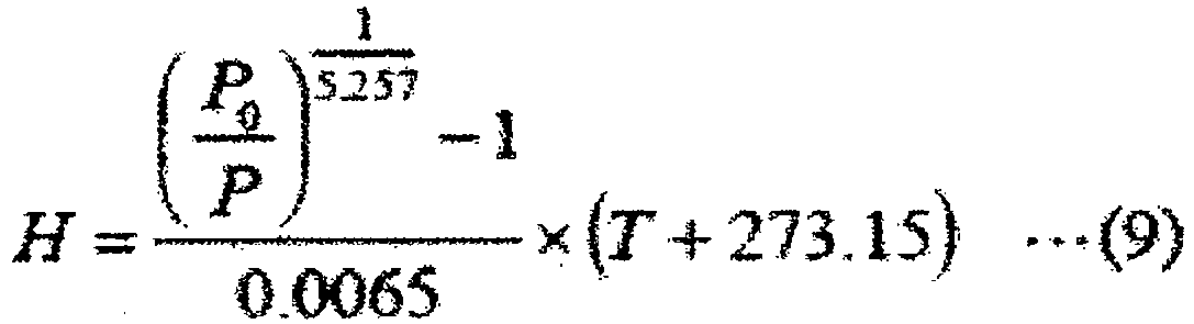
- In Formula (9), P0 and T are the following numerical values.
- P0: sea level atmospheric pressure
- T: temperature
- In another case, for example, where the
pressure detector 300 in thesensor chip 10c detects the pressure (about 0.1 MPa to 1 MPa) of a gas filled in a tire, by installing the sensor chip in the tire or inside a tire wheel, the rotation of the tire or the tire wheel can be detected by theacceleration detector 20 and theangular velocity detector 30, and at the same time, the pressure inside the tire can be detected by thepressure detector 300. With this configuration, it is possible to perform monitoring of the state of the tire with high accuracy and to enhance running safety of a vehicle. - While the embodiment of the present invention has been described above, the inertial force sensor of the present invention is not limited to these, and various modifications are possible. For example, each of the number of the first laminate. 1, the
second laminate 2, and the third laminate may be two. Moreover, in each of the laminates, there may be two or more detectors, or two or more types of detectors. Moreover, thechip packages 4 and 4a may employ a resin substrate or ceramics instead of thelead frame 72 and may be formed as a ball grud array (BGA) package in which electrodes are extracted onto the back surface of the substrate by solder balls. Reference Signs List -
- 1
- first laminate
- 1a
- first substrate (first laminate)
- 1b
- second substrate (first laminate)
- 1c
- oxide film (first laminate)
- 1d
- insulating film (first laminate)
- 2
- second laminate
- 2a
- first substrate (second laminate)
- 2b
- second substrate (second laminate)
- 2c
- oxide film (second laminate)
- 2d
- insulating film (second laminate)
- 3
- semiconductor chip
- 3a
- semiconductor chip
- 3b
- semiconductor chip
- 4
- chip package
- 4a
- chip package (modification)
- 10
- sensor chip
- 10a
- sensor chip
- 10b
- sensor chip
- 10c
- sensor chip
- 20
- acceleration detector (y-axis direction)
- 20a
- acceleration detector (x-axis direction)
- 20b
- acceleration detector
- 20c
- acceleration detector (z-axis direction)
- 21
- weight
- 21b
- weight
- 22a
- beam
- 22b
- beam
- 22c
- beam
- 22d
- beam
- 22ab
- beam
- 22bb
- beam
- 22cb
- beam
- 22db
- beam
- 23a
- fixed portion
- 23b
- fixed portion
- 23c
- fixed portion
- 23d
- fixed portion
- 23ab
- fixed portion
- 23bb
- fixed portion
- 23cb
- fixed portion
- 23db
- fixed portion
- 24a
- electrode
- 24b
- electrode (for differential)
- 24ab
- electrode
- 24bb
- electrode (for differential)
- 25a
- electrode (for external circuit connection)
- 25b
- electrode (for external circuit connection)
- 25ab
- electrode (for external circuit connection)
- 25bb
- electrode (for external circuit connection)
- 26a
- electrode (for external circuit connection)
- 29
- cavity
- 30
- angular velocity detector (about z-axis)
- 30a
- angular velocity detector (about z-axis)
- 30b
- angular velocity detector (about y-axis)
- 30q1
- angular velocity detector (left side)
- 30q2
- angular velocity detector (right side)
- 31
- first weight
- 31q1
- first weight (left side)
- 31q2
- first weight (right side)
- 32a
- first beam
- 32b
- first beam
- 32c
- first beam
- 32d
- first beam
- 33a
- fixed portion
- 33b
- fixed portion
- 33c
- fixed portion
- 33d
- fixed portion
- 34a
- first electrode
- 34b
- first electrode
- 35a
- electrode (for external circuit connection)
- 35b
- electrode (for external circuit connection)
- 36a
- electrode (for external circuit connection)
- 37
- second weight
- 37b
- second weight
- 37q1
- second weight (left side)
- 37q2
- second weight (right side)
- 38a
- second beam
- 38b
- second beam
- 38c
- second beam
- 38d
- second beam
- 38ab
- second beam
- 38bb
- second beam
- 38cb
- second beam
- 38db
- second beam
- 39a
- second electrode
- 39b
- second electrode (for differential)
- 39ab
- second electrode
- 39bb
- second electrode (for differential)
- 40a
- electrode (for external circuit connection)
- 40b
- electrode (for external circuit connection)
- 40ab
- electrode (for external circuit connection)
- 41
- third beam
- 49
- cavity
- 50
- penetrating electrode
- 50a
- penetrating electrode
- 51
- insulating film (penetrating electrode outer periphery)
- 51a
- insulating film (penetrating electrode outer periphery)
- 52
- electrode
- 52a
- electrode
- 60
- penetrating electrode
- 60a
- penetrating electrode
- 61
- insulating film (penetrating electrode outer periphery)
- 61a
- insulating film (penetrating electrode outer periphery)
- 62
- electrode
- 70
- adhesive
- 70a
- adhesive
- 71
- first wire bonding
- 72
- lead frame
- 73
- adhesive
- 74
- second wire bonding
- 75
- resin
- 76
- conductive material
- 81
- electrode
- 82
- electrode
- 100
- integrated circuit (for acceleration)
- 101
- carrier wave (for acceleration)
- 102
- CV converter (for acceleration)
- 103
- synchronous detector (for acceleration)
- 104
- acceleration signal (for acceleration)
- 200
- integrated circuit (for angular velocity)
- 201
- carrier wave (for angular velocity)
- 202
- CV converter (for angular velocity)
- 203
- synchronous detector (for angular velocity)
- 204
- angular velocity signal
- 205
- oscillator
- 206
- amplifier
- 300
- pressure detector
- 301
- third laminate
- 301a
- first substrate (third laminate)
- 301b
- second substrate (third laminate)
- 301c
- oxide film (third laminate)
- 302
- deformable portion
- 303
- cavity
- 304
- electrode
- 305
- insulating portion


Claims (17)
- An inertial force sensor comprising a layer in which a detector is formed,
wherein the layer is a laminated structure in which two or more layers are laminated. - The inertial force sensor according to claim 1,
wherein the detector includes a movable body and an electrode. - The inertial force sensor according to claim 2,
wherein at least one pair of detectors is arranged such that the movable body and the electrode are formed in a same layer. - The inertial force sensor according to claim 2,
wherein at least one pair of detectors is arranged such that the movable body and the electrode are formed in mutually different layers. - The inertial force sensor according to claim 4,
wherein, in the detector in which the movable body and the electrode are formed in mutually different layers,
the electrode is formed in the same layer as the layer in which the movable body of another detector is formed. - The inertial force sensor according to any one of claims 1 to 5,
wherein the at least one pair of detectors are provided in two sets or more, and arranged in an array. - The inertial force sensor according to any one of claims 1 to 6,
wherein a signal of the sensor is extracted solely on one side of the laminated structure. - The inertial force sensor according to claim 7,
wherein a signal of the detector passes through the laminated structure. - The inertial force sensor according to any one of claims 1 to 8,
wherein at least one layer has a structure of a microelectromechanical system. - The inertial force sensor according to any one of claims 1 to 9,
wherein at least one detector has a portion that detects pressure. - The inertial force sensor according to any one of claims 1 to 10,
wherein at least one layer is a layer in which an LSI element is formed. - The inertial force sensor according to any one of claims 1 to 10,
wherein at least one layer is a layer in which a semiconductor memory is formed. - The inertial force sensor according to any one of claims 1 to 10,
wherein at least one layer is a layer in which a circuit that converts a digital signal into an analog signal is formed. - The inertial force sensor according to any one of claims 1 to 10,
wherein at least one layer is a layer in which a circuit that converts an analog signal into a digital signal is formed. - The inertial force sensor according to any one of claims 1 to 10,
wherein at least one layer is a layer in which an LSI element is formed, and
at least one layer is a layer in which a semiconductor memory is formed. - The inertial force sensor according to any one of claims 1 to 15,
wherein at least one pair of detectors is airtight against the outside of the laminated structure. - The inertial force sensor according to any one of claims 1 to 16,
wherein at least one pair of detectors detects one of acceleration and angular velocity, and
at least one pair of detectors detects one of acceleration and angular velocity.
Applications Claiming Priority (2)
| Application Number | Priority Date | Filing Date | Title |
|---|---|---|---|
| JP2015192519 | 2015-09-30 | ||
| PCT/JP2016/072713 WO2017056697A1 (en) | 2015-09-30 | 2016-08-03 | Inertia sensor |
Publications (2)
| Publication Number | Publication Date |
|---|---|
| EP3358357A1 true EP3358357A1 (en) | 2018-08-08 |
| EP3358357A4 EP3358357A4 (en) | 2019-11-06 |
Family
ID=58427456
Family Applications (1)
| Application Number | Title | Priority Date | Filing Date |
|---|---|---|---|
| EP16850874.5A Withdrawn EP3358357A4 (en) | 2015-09-30 | 2016-08-03 | SENSOR OF INERTIA |
Country Status (5)
| Country | Link |
|---|---|
| US (1) | US20180162723A1 (en) |
| EP (1) | EP3358357A4 (en) |
| JP (1) | JP6343102B2 (en) |
| CN (1) | CN108450008A (en) |
| WO (1) | WO2017056697A1 (en) |
Families Citing this family (6)
| Publication number | Priority date | Publication date | Assignee | Title |
|---|---|---|---|---|
| JP6420442B1 (en) * | 2017-10-16 | 2018-11-07 | 株式会社ワコー | Power generation element |
| US11192664B2 (en) * | 2018-12-10 | 2021-12-07 | Hamilton Sundstrand Corporation | Smart application for aircraft performance data collection |
| JP2023515140A (en) * | 2020-02-21 | 2023-04-12 | ニットウ,インク. | Tires and tire sensors |
| CN215453267U (en) * | 2021-06-22 | 2022-01-07 | 瑞声声学科技(深圳)有限公司 | Bone conduction sensor assembly |
| EP4446281A1 (en) * | 2023-04-14 | 2024-10-16 | Murata Manufacturing Co., Ltd. | Double layer mems devices and method of manufacture |
| CN116952309B (en) * | 2023-09-20 | 2023-12-15 | 中国船舶集团有限公司第七〇七研究所 | Posture and vibration monitoring method applied to directional measurement equipment |
Family Cites Families (13)
| Publication number | Priority date | Publication date | Assignee | Title |
|---|---|---|---|---|
| US5786744A (en) * | 1994-03-24 | 1998-07-28 | Honda Giken Kogyo Kabushiki Kaisha | Hybrid sensor |
| JP3435665B2 (en) * | 2000-06-23 | 2003-08-11 | 株式会社村田製作所 | Composite sensor element and method of manufacturing the same |
| JP2007292499A (en) * | 2006-04-21 | 2007-11-08 | Sony Corp | Motion sensor and manufacturing method thereof |
| DE102006024671A1 (en) * | 2006-05-26 | 2007-11-29 | Robert Bosch Gmbh | Micromechanical unit for e.g. monitoring e.g. tire pressure, has diaphragm and seismic mass arranged at distance from each other and arranged one above other, where seismic mass is movable parallel to layer levels |
| JP4929918B2 (en) * | 2006-08-21 | 2012-05-09 | パナソニック株式会社 | Compound sensor |
| JP2010217170A (en) * | 2009-02-17 | 2010-09-30 | Seiko Epson Corp | Composite sensor and electronic device |
| WO2011064677A2 (en) * | 2009-11-24 | 2011-06-03 | Yost Engineering, Inc. | Combining redundant inertial sensors to create a virtual sensor output |
| US8387464B2 (en) * | 2009-11-30 | 2013-03-05 | Freescale Semiconductor, Inc. | Laterally integrated MEMS sensor device with multi-stimulus sensing |
| JP5527015B2 (en) * | 2010-05-26 | 2014-06-18 | セイコーエプソン株式会社 | Element structure, inertial sensor, electronic equipment |
| US9231119B2 (en) * | 2011-03-11 | 2016-01-05 | Panasonic Intellectual Property Management Co., Ltd. | Sensor |
| US9564413B2 (en) * | 2011-09-15 | 2017-02-07 | STATS ChipPAC Pte. Ltd. | Semiconductor device and method of forming semiconductor die with active region responsive to external stimulus |
| JP2013171009A (en) * | 2012-02-23 | 2013-09-02 | Hitachi Automotive Systems Ltd | Inertial force sensor |
| JP5978170B2 (en) * | 2013-06-28 | 2016-08-24 | 日立オートモティブシステムズ株式会社 | Transfer mold type sensor device |
-
2016
- 2016-08-03 CN CN201680057926.1A patent/CN108450008A/en active Pending
- 2016-08-03 US US15/737,389 patent/US20180162723A1/en not_active Abandoned
- 2016-08-03 WO PCT/JP2016/072713 patent/WO2017056697A1/en not_active Ceased
- 2016-08-03 EP EP16850874.5A patent/EP3358357A4/en not_active Withdrawn
- 2016-08-03 JP JP2017542980A patent/JP6343102B2/en not_active Expired - Fee Related
Also Published As
| Publication number | Publication date |
|---|---|
| CN108450008A (en) | 2018-08-24 |
| JPWO2017056697A1 (en) | 2018-03-29 |
| JP6343102B2 (en) | 2018-06-13 |
| WO2017056697A1 (en) | 2017-04-06 |
| US20180162723A1 (en) | 2018-06-14 |
| EP3358357A4 (en) | 2019-11-06 |
Similar Documents
| Publication | Publication Date | Title |
|---|---|---|
| US20250155469A1 (en) | Mems tri-axial accelerometer with one or more decoupling elements | |
| US8739626B2 (en) | Micromachined inertial sensor devices | |
| US9247664B2 (en) | Electronic device and manufacturing method thereof, electronic apparatus, and moving body | |
| JP6343102B2 (en) | Inertial force sensor | |
| EP2462408B1 (en) | Micromachined inertial sensor devices | |
| US8978475B2 (en) | MEMS proof mass with split z-axis portions | |
| US9062972B2 (en) | MEMS multi-axis accelerometer electrode structure | |
| JP5037690B2 (en) | Micro electromechanical system | |
| EP2284545B1 (en) | Coplanar proofmasses employable to sense acceleration along three axes | |
| EP2616772A2 (en) | Micromachined monolithic 3-axis gyroscope with single drive | |
| JP2013250133A (en) | Electronic device, method of manufacturing electronic device, and electronic apparatus | |
| JP2012521565A (en) | Vertically integrated MEMS acceleration transducer | |
| US20230266360A1 (en) | Accelerometer, inertial measurement unit imu, and electronic device | |
| CN102388292A (en) | Environmentally robust disc resonator gyroscope | |
| WO2018088065A1 (en) | Sensor element, inertia sensor and electronic apparatus | |
| JP2010085143A (en) | Acceleration sensor | |
| US11680797B2 (en) | Physical quantity sensor | |
| JP2018132349A (en) | Physical amount detector and physical amount detection device | |
| Rivers et al. | Micro IMU utilizing folded cube approach | |
| JP5257115B2 (en) | Mechanical quantity sensor and manufacturing method thereof | |
| KR20140028991A (en) | Overlay type inertial sensor and control methode thereof |
Legal Events
| Date | Code | Title | Description |
|---|---|---|---|
| STAA | Information on the status of an ep patent application or granted ep patent |
Free format text: STATUS: THE INTERNATIONAL PUBLICATION HAS BEEN MADE |
|
| PUAI | Public reference made under article 153(3) epc to a published international application that has entered the european phase |
Free format text: ORIGINAL CODE: 0009012 |
|
| STAA | Information on the status of an ep patent application or granted ep patent |
Free format text: STATUS: REQUEST FOR EXAMINATION WAS MADE |
|
| 17P | Request for examination filed |
Effective date: 20171128 |
|
| AK | Designated contracting states |
Kind code of ref document: A1 Designated state(s): AL AT BE BG CH CY CZ DE DK EE ES FI FR GB GR HR HU IE IS IT LI LT LU LV MC MK MT NL NO PL PT RO RS SE SI SK SM TR |
|
| AX | Request for extension of the european patent |
Extension state: BA ME |
|
| DAV | Request for validation of the european patent (deleted) | ||
| DAX | Request for extension of the european patent (deleted) | ||
| RIC1 | Information provided on ipc code assigned before grant |
Ipc: H01L 29/84 20060101ALI20190517BHEP Ipc: G01P 15/08 20060101ALI20190517BHEP Ipc: G01D 21/02 20060101ALI20190517BHEP Ipc: G01L 9/00 20060101ALI20190517BHEP Ipc: G01P 15/125 20060101ALI20190517BHEP Ipc: G01C 19/5783 20120101AFI20190517BHEP Ipc: G01P 15/18 20130101ALI20190517BHEP Ipc: G01P 1/02 20060101ALI20190517BHEP |
|
| A4 | Supplementary search report drawn up and despatched |
Effective date: 20191004 |
|
| RIC1 | Information provided on ipc code assigned before grant |
Ipc: G01P 15/18 20130101ALI20190927BHEP Ipc: G01C 19/5783 20120101AFI20190927BHEP Ipc: G01D 21/02 20060101ALI20190927BHEP Ipc: G01P 1/02 20060101ALI20190927BHEP Ipc: G01P 15/125 20060101ALI20190927BHEP Ipc: G01P 15/08 20060101ALI20190927BHEP Ipc: H01L 29/84 20060101ALI20190927BHEP Ipc: G01L 9/00 20060101ALI20190927BHEP |
|
| STAA | Information on the status of an ep patent application or granted ep patent |
Free format text: STATUS: THE APPLICATION IS DEEMED TO BE WITHDRAWN |
|
| 18D | Application deemed to be withdrawn |
Effective date: 20200603 |