EP3358305A1 - Vehicular display device - Google Patents
Vehicular display device Download PDFInfo
- Publication number
- EP3358305A1 EP3358305A1 EP15905365.1A EP15905365A EP3358305A1 EP 3358305 A1 EP3358305 A1 EP 3358305A1 EP 15905365 A EP15905365 A EP 15905365A EP 3358305 A1 EP3358305 A1 EP 3358305A1
- Authority
- EP
- European Patent Office
- Prior art keywords
- display
- arrow
- display device
- arrows
- guide route
- Prior art date
- Legal status (The legal status is an assumption and is not a legal conclusion. Google has not performed a legal analysis and makes no representation as to the accuracy of the status listed.)
- Granted
Links
Images




Classifications
-
- G—PHYSICS
- G01—MEASURING; TESTING
- G01C—MEASURING DISTANCES, LEVELS OR BEARINGS; SURVEYING; NAVIGATION; GYROSCOPIC INSTRUMENTS; PHOTOGRAMMETRY OR VIDEOGRAMMETRY
- G01C21/00—Navigation; Navigational instruments not provided for in groups G01C1/00 - G01C19/00
- G01C21/26—Navigation; Navigational instruments not provided for in groups G01C1/00 - G01C19/00 specially adapted for navigation in a road network
- G01C21/34—Route searching; Route guidance
- G01C21/36—Input/output arrangements for on-board computers
- G01C21/3626—Details of the output of route guidance instructions
- G01C21/3632—Guidance using simplified or iconic instructions, e.g. using arrows
-
- G—PHYSICS
- G01—MEASURING; TESTING
- G01C—MEASURING DISTANCES, LEVELS OR BEARINGS; SURVEYING; NAVIGATION; GYROSCOPIC INSTRUMENTS; PHOTOGRAMMETRY OR VIDEOGRAMMETRY
- G01C21/00—Navigation; Navigational instruments not provided for in groups G01C1/00 - G01C19/00
- G01C21/26—Navigation; Navigational instruments not provided for in groups G01C1/00 - G01C19/00 specially adapted for navigation in a road network
- G01C21/34—Route searching; Route guidance
- G01C21/36—Input/output arrangements for on-board computers
-
- G—PHYSICS
- G01—MEASURING; TESTING
- G01C—MEASURING DISTANCES, LEVELS OR BEARINGS; SURVEYING; NAVIGATION; GYROSCOPIC INSTRUMENTS; PHOTOGRAMMETRY OR VIDEOGRAMMETRY
- G01C21/00—Navigation; Navigational instruments not provided for in groups G01C1/00 - G01C19/00
- G01C21/26—Navigation; Navigational instruments not provided for in groups G01C1/00 - G01C19/00 specially adapted for navigation in a road network
-
- B—PERFORMING OPERATIONS; TRANSPORTING
- B60—VEHICLES IN GENERAL
- B60K—ARRANGEMENT OR MOUNTING OF PROPULSION UNITS OR OF TRANSMISSIONS IN VEHICLES; ARRANGEMENT OR MOUNTING OF PLURAL DIVERSE PRIME-MOVERS IN VEHICLES; AUXILIARY DRIVES FOR VEHICLES; INSTRUMENTATION OR DASHBOARDS FOR VEHICLES; ARRANGEMENTS IN CONNECTION WITH COOLING, AIR INTAKE, GAS EXHAUST OR FUEL SUPPLY OF PROPULSION UNITS IN VEHICLES
- B60K35/00—Instruments specially adapted for vehicles; Arrangement of instruments in or on vehicles
- B60K35/20—Output arrangements, i.e. from vehicle to user, associated with vehicle functions or specially adapted therefor
- B60K35/21—Output arrangements, i.e. from vehicle to user, associated with vehicle functions or specially adapted therefor using visual output, e.g. blinking lights or matrix displays
- B60K35/23—Head-up displays [HUD]
- B60K35/235—Head-up displays [HUD] with means for detecting the driver's gaze direction or eye points
-
- G—PHYSICS
- G01—MEASURING; TESTING
- G01C—MEASURING DISTANCES, LEVELS OR BEARINGS; SURVEYING; NAVIGATION; GYROSCOPIC INSTRUMENTS; PHOTOGRAMMETRY OR VIDEOGRAMMETRY
- G01C21/00—Navigation; Navigational instruments not provided for in groups G01C1/00 - G01C19/00
- G01C21/26—Navigation; Navigational instruments not provided for in groups G01C1/00 - G01C19/00 specially adapted for navigation in a road network
- G01C21/34—Route searching; Route guidance
- G01C21/36—Input/output arrangements for on-board computers
- G01C21/3626—Details of the output of route guidance instructions
- G01C21/365—Guidance using head up displays or projectors, e.g. virtual vehicles or arrows projected on the windscreen or on the road itself
-
- G—PHYSICS
- G06—COMPUTING OR CALCULATING; COUNTING
- G06T—IMAGE DATA PROCESSING OR GENERATION, IN GENERAL
- G06T19/00—Manipulating three-dimensional [3D] models or images for computer graphics
- G06T19/006—Mixed reality
-
- G—PHYSICS
- G09—EDUCATION; CRYPTOGRAPHY; DISPLAY; ADVERTISING; SEALS
- G09G—ARRANGEMENTS OR CIRCUITS FOR CONTROL OF INDICATING DEVICES USING STATIC MEANS TO PRESENT VARIABLE INFORMATION
- G09G5/00—Control arrangements or circuits for visual indicators common to cathode-ray tube indicators and other visual indicators
- G09G5/36—Control arrangements or circuits for visual indicators common to cathode-ray tube indicators and other visual indicators characterised by the display of a graphic pattern, e.g. using an all-points-addressable [APA] memory
- G09G5/363—Graphics controllers
-
- G—PHYSICS
- G09—EDUCATION; CRYPTOGRAPHY; DISPLAY; ADVERTISING; SEALS
- G09G—ARRANGEMENTS OR CIRCUITS FOR CONTROL OF INDICATING DEVICES USING STATIC MEANS TO PRESENT VARIABLE INFORMATION
- G09G2340/00—Aspects of display data processing
- G09G2340/12—Overlay of images, i.e. displayed pixel being the result of switching between the corresponding input pixels
-
- G—PHYSICS
- G09—EDUCATION; CRYPTOGRAPHY; DISPLAY; ADVERTISING; SEALS
- G09G—ARRANGEMENTS OR CIRCUITS FOR CONTROL OF INDICATING DEVICES USING STATIC MEANS TO PRESENT VARIABLE INFORMATION
- G09G2340/00—Aspects of display data processing
- G09G2340/14—Solving problems related to the presentation of information to be displayed
-
- G—PHYSICS
- G09—EDUCATION; CRYPTOGRAPHY; DISPLAY; ADVERTISING; SEALS
- G09G—ARRANGEMENTS OR CIRCUITS FOR CONTROL OF INDICATING DEVICES USING STATIC MEANS TO PRESENT VARIABLE INFORMATION
- G09G2380/00—Specific applications
- G09G2380/10—Automotive applications
Definitions
- the present invention relates to a vehicular display device which displays information in a vehicle.
- a display (Head-Up Display: HUD) device for augmented reality (AR) display which displays an image in a manner superimposed on an outside view ahead of a windshield
- the display device displays guide figures along a guide route in a manner superimposed on a forward view in a traveling direction on a road on which a vehicle is traveling. For example, for route guidance and the like, the display device displays arrows indicating a course as if the arrows were drawn on the ground.
- Patent Literature 1 Japanese Patent No. 4560090
- Patent Literature 1 when the guide figure displayed on the road in the traveling direction is far from a host vehicle or extends horizontally, the guide figure is hard to read.
- the guide figure is an arrow
- the guide figure is hard to read when a point where the arrow is laid is far or when the direction in which the arrow is pointing is horizontal or an oblique direction close to horizontal. This is because the arrow extending in the direction close to horizontal has a small vertical dimension as viewed from the driver.
- the arrow can have a sufficient vertical dimension and is easy to read even when the arrow extends in the direction close to horizontal.
- the presence thereof can be easily recognized but distinguishability between a front end and a rear end of the arrow cannot be improved.
- An object of the present invention is to provide a vehicular display device which allows easy reading of a guide figure displayed on a road in a traveling direction.
- a display controller draws an arrow having a shaft with an arrowhead at one end of the shaft, as a guide figure for guidance along a guide route calculated by a navigation device, such that the arrow looks like a three-dimensional object in which a portion of the arrow with a large width has a large height and a portion of the arrow with a small width has a small height.
- a display displays an image as drawn in a display area provided to overlap a position of a windshield.
- a vehicular display device according to embodiments of the present invention is described below in detail with reference to the drawings.
- Fig. 1 is a diagram illustrating a configuration of a vehicular display device according to Embodiment 1 of the present invention.
- the vehicular display device displays a guide route to a destination of a host vehicle.
- the vehicular display device includes a GPS (Global Positioning System) antenna 11, a geomagnetic sensor 12, a navigation device 13, a viewpoint detection camera 14, a viewpoint position determiner 15, a display controller 16, and a display 17.
- GPS Global Positioning System
- the GPS antenna 11 receives GPS signals from not-illustrated GPS satellites and outputs the received GPS signals to the navigation device 13 as GPS information.
- the geomagnetic sensor 12 detects azimuth of the direction in which the vehicle is facing (azimuth of the traveling direction of the vehicle) and outputs the detected azimuth to the navigation device 13 as azimuth information.
- the navigation device 13 calculates the guide route by using the GPS information from the GPS antenna 11, the azimuth information from the geomagnetic sensor 12, and information acquired in itself.
- the navigation device 13 generates guidance route information for performing guidance along the calculated route and outputs the guide route information to the display controller 16. Details of the navigation device 13 are described later.
- the viewpoint detection camera 14 captures an image including the positions of the eyes of a driver and outputs the captured image to the viewpoint position determiner 15 as viewpoint image information.
- the viewpoint position determiner 15 determines a viewpoint position of the driver based on the viewpoint image information sent from the viewpoint detection camera 14 and outputs the determination result to the display controller 16 as viewpoint position information.
- the display controller 16 generates an image to be displayed on the display 17 based on the guide route information and the like sent from the navigation device 13 and the viewpoint position information sent from the viewpoint position determiner 15.
- the display controller 16 draws arrows each having a shaft with an arrowhead at one end of the shaft, as guide figures for guidance along the guide route calculated by the navigation device 13, such that each arrow looks like a three-dimensional object in which a portion of the arrow with a large width has a large height and a portion of the arrow with a small width has a small height.
- the display 17 includes a projection unit which projects a video, a screen and a Fresnel mirror which reflect the video, and the like, and displays an image in a display area provided to overlap the position of a windshield included in the vehicle.
- the display 17 is a head-up display which can display the image in a manner superimposed on a forward view ahead of the vehicle by displaying the image reflected by a mirror, on a near side of the windshield as a virtual image.
- the display 17 is not limited to this type of head-up display.
- the display 17 may be a combiner type head-up display using a transparent panel instead of displaying the image on the windshield or may employ a method of directly displaying the image on the windshield.
- the head-up display in the embodiment may be any type as long as the driver can see the information, displayed by the head-up display in a manner superimposed on a view seen by the driver from the windshield, without looking down.
- the image based on the display image information generated by the display controller 16 is thereby displayed within the field of view of a person.
- the navigation device 13 includes intersection data 21, map data 22, an acceleration sensor 23, a gyroscope sensor 24, and a calculator 25.
- intersection data 21 is data indicating characteristics and the like of each intersection and is acquired from, for example, a disc device or a center via a communication line and a communication device (both are not illustrated).
- the intersection data is read by the calculator 25.
- the map data 22 is data acquired from, for example, the disc device or the center via the communication line and the communication device like the intersection data 21, and is used for drawing of a map, calculation of the guide route, generation of the guide route information to be outputted to the display controller 16, and the like.
- the map data 22 is read by the calculator 25.
- the acceleration sensor 23 detects the acceleration of the host vehicle and outputs the detected acceleration to the calculator 25 as acceleration information.
- the gyroscope sensor 24 detects the angular velocity of the host vehicle and outputs the detected angular velocity to the calculator 25 as angular velocity information.
- the calculator 25 calculates the current position of the host vehicle by using the map data 22 and the GPS information sent from the GPS antenna 11. In the calculation, the vehicle sometimes cannot receive the GPS signals when traveling, for example, in a tunnel, under an elevated road, or between tall buildings. Accordingly, the calculator 25 calculates the current position by autonomous navigation based on the map data 22, the azimuth information from the geomagnetic sensor 12, the acceleration information from the acceleration sensor 23, and the angular velocity information from the gyroscope sensor 24. The calculator 25 creates the guide route information based on the calculated current position and outputs the created guide route information to the display controller 16.
- the vehicular display device creates arrows (route guide arrows) to be displayed to appear in a manner superimposed on a ground as illustrated in, for example, Fig. 3 for route guidance.
- a guidance flag is first acquired (step S11). Specifically, the display controller 16 acquires the guidance flag from the navigation device 13.
- the guidance flag is a flag instructing whether to perform the guidance along the guide route or not. The guidance along the guide route using the arrows is performed only when the guidance flag is set to on.
- step S12 whether the guidance flag is on or not is checked. Specifically, the display controller 16 checks whether the guidance flag acquired in step S11 is on or not. When the guidance flag is determined not to be on in step S12, the display controller 16 determines that the guidance is unnecessary, and the processing is terminated.
- step S13 the guide route information is acquired (step S13). Specifically, the display controller 16 acquires the start position, the direction, and the length of each arrow from the navigation device 13 as the guide route information.
- the guide route information is calculated in advance depending on a route search operation performed by the driver and is stored in the navigation device 13.
- the viewpoint position is acquired (step S14). Specifically, the display controller 16 acquires the viewpoint position information from the viewpoint position determiner 15.
- step S15 arrangement of arrows drawn by lines in the display area is calculated (step S15). Specifically, the display controller 16 arranges arrows drawn by lines in a manner superimposed on the guide route as viewed from the driver, by using the guide route information acquired in step S13 and the viewpoint position acquired in step S14.
- step S16 three-dimensional looking arrows are drawn (step S16). Specifically, the display controller 16 draws arrows to be displayed in the display area by converting the arrows drawn by lines and arranged in the display area in step S15 to arrows looking three-dimensional as viewed from the viewpoint of the driver indicated by the viewpoint position information acquired in step S14. Steps of drawing the three-dimensional looking arrows are described in detail later.
- a display image is outputted to the display 17 (step S17).
- the display controller 16 outputs the image drawn in step S16 to the display 17 as display image information.
- the display 17 thereby generates an image based on the display image information from the display controller 16, displays the generated image on a liquid crystal display or the like, and causes the image to be reflected on a mirror or the windshield to display the image directly within the field of view of a person. Thereafter, the sequence returns to step S12 and the aforementioned processes are repeated.
- three-dimensional looking arrows M30a, M30b, M30c, M30d, and M30e are displayed in a manner superimposed on the guide route in the display area provided to overlap an outside view ahead of the windshield.
- Figs. 5 to 7 are views for explaining display examples of arrows in existing vehicular display devices and, in each view, arrows of the same pattern (including multiple arrows) are drawn on the ground to be arranged in traveling directions of the vehicle.
- the distant arrows are viewed at angles close to an edge-on angle and a vertical arrow M21v has a small dimension and is hard to read. This is particularly significant for a horizontal arrow M21h.
- arrows M22 each with an increased width as illustrated in Fig. 6 .
- arrows M23 which are three-dimensional objects each with a certain thickness can be used to improve the noticeability of distant horizontal arrows M23h.
- the distant horizontal arrows M23h are noticeable, but it is hard to read the direction in which each arrow is pointing.
- each of arrows M33 is displayed to look like a three-dimensional arch-shaped object in which a portion of the arrow with a large width has a large height and a portion of the arrow with a small width has a small height, the direction in which the arrow is pointing is easy to read.
- the shape of an arrowhead in each of distant horizontal arrows M33h is easy to read, the direction in which the arrow is pointing is easy to read.
- the arrows are drawn in the three-dimensional arch shape which is raised in the center portion in the width direction as in the example illustrated in Fig. 8
- the arrows may be drawn like arrows M34 with a three-dimensional ridge shape which is bent at the center in the width direction as illustrated in Fig. 9 .
- the arrows may be each drawn to look like a three-dimensional cockscomb-shaped object whose height changes only in a center portion M35b in the width direction.
- a configuration of a vehicular display device according to Embodiment 2 of the present invention is the same as the configuration of the vehicular display device according to Embodiment 1 illustrated in Fig. 1 , and is different only in the shape of the arrows displayed in the display 17. Accordingly, description is given below mainly of portions different from Embodiment 1.
- the navigation device 13 sends the display controller 16 a line configured by a straight line and a curved line as one mode of the guide route information.
- step S11 to S12 are the same as those in the flowchart illustrated in Fig. 2 , description thereof is omitted.
- step S13 assume that the guide route indicated by the guide route information acquired from the navigation device 13 indicates "left turn” at the next intersection.
- the display controller 16 acquires a guide route curved to the left from the navigation device 13.
- the viewpoint position is acquired (step S14). Specifically, the display controller 16 acquires the viewpoint position information from the viewpoint position determiner 15.
- step S15 arrangement of an arrow drawn by lines in the display area is calculated (step S15). Specifically, the display controller 16 arranges a curved arrow drawn by lines in a manner superimposed on the guide route as viewed from the driver, by using the information on the guide route curved to the left which is acquired in step S13 and the viewpoint position which is acquired in step S14.
- step S16 the arrow is drawn to look three-dimensional (step S16).
- step S17 the display image is outputted to the display (step S17).
- the display 17 thereby generates an image based on the display image information from the display controller 16, displays the generated image on the liquid crystal display or the like, and causes the image to be reflected on the mirror or the windshield to display the image directly within the field of view of a person. Thereafter, the sequence returns to step S12 and the aforementioned processes are repeated.
- the display 17 displays an arrow instructing a left turn at the next intersection, for example, an arrow M33A having a shaft curved to the left as illustrated in Fig. 11 .
- the arrow M33A is configured by an arrow M33a having a shape of an arrowhead, a linear arrow M33b connected to the arrow M33a, and an arrow M33c bent relative to the arrow M33b.
- the arrow used for guidance in an intersection is displayed as an arrow looking like a three-dimensional arch-shaped object in which a portion of the arrow with a large width has a large height and a portion of the arrow with a small width has a small height, the direction in which the arrow is pointing is easy to read.
- the shape of the arrowhead in the distant horizontal arrow is easy to read, the direction in which the arrow is pointing is easy to read.
- the arrow may be drawn to look like the three-dimensional arch-shaped object, the arrow may be drawn to look like a three-dimensional ridge-shaped object which is bent at the center in the width direction as in Embodiment 1. Moreover, the arrow may be drawn to look like a three-dimensional cockscomb-shaped object whose height changes only in a center portion in the width direction.
Landscapes
- Engineering & Computer Science (AREA)
- Remote Sensing (AREA)
- Radar, Positioning & Navigation (AREA)
- Automation & Control Theory (AREA)
- General Physics & Mathematics (AREA)
- Physics & Mathematics (AREA)
- Mechanical Engineering (AREA)
- Chemical & Material Sciences (AREA)
- Transportation (AREA)
- Combustion & Propulsion (AREA)
- Computer Graphics (AREA)
- Computer Hardware Design (AREA)
- Theoretical Computer Science (AREA)
- General Engineering & Computer Science (AREA)
- Software Systems (AREA)
- Navigation (AREA)
Abstract
Description
- The present invention relates to a vehicular display device which displays information in a vehicle.
- As a conventional vehicular display device, there is known a display (Head-Up Display: HUD) device for augmented reality (AR) display which displays an image in a manner superimposed on an outside view ahead of a windshield (see Patent Literature 1). The display device displays guide figures along a guide route in a manner superimposed on a forward view in a traveling direction on a road on which a vehicle is traveling. For example, for route guidance and the like, the display device displays arrows indicating a course as if the arrows were drawn on the ground.
- Patent Literature 1: Japanese Patent No.
4560090 - However, in Patent Literature 1, when the guide figure displayed on the road in the traveling direction is far from a host vehicle or extends horizontally, the guide figure is hard to read. In the case where the guide figure is an arrow, the guide figure is hard to read when a point where the arrow is laid is far or when the direction in which the arrow is pointing is horizontal or an oblique direction close to horizontal. This is because the arrow extending in the direction close to horizontal has a small vertical dimension as viewed from the driver.
- If the arrow is drawn three-dimensionally, the arrow can have a sufficient vertical dimension and is easy to read even when the arrow extends in the direction close to horizontal. In the three-dimensionally-drawn arrow whose thickness is simply increased, the presence thereof can be easily recognized but distinguishability between a front end and a rear end of the arrow cannot be improved.
- An object of the present invention is to provide a vehicular display device which allows easy reading of a guide figure displayed on a road in a traveling direction.
- A display controller draws an arrow having a shaft with an arrowhead at one end of the shaft, as a guide figure for guidance along a guide route calculated by a navigation device, such that the arrow looks like a three-dimensional object in which a portion of the arrow with a large width has a large height and a portion of the arrow with a small width has a small height. A display displays an image as drawn in a display area provided to overlap a position of a windshield.
-
- [
Fig. 1] Fig. 1 is a block diagram illustrating a configuration of a vehicular display device according to Embodiment 1 of the present invention. - [
Fig. 2] Fig. 2 is a flowchart for explaining an operation of the vehicular display device according to Embodiment 1 of the present invention. - [
Fig. 3] Fig. 3 is a view for explaining an example of arrows (route guide arrows) which are display targets in the vehicular display device according to Embodiment 1 of the present invention. - [
Fig. 4] Fig. 4 is a view for explaining steps of drawing three-dimensional looking arrows in the vehicular display device according to Embodiment 1 of the present invention. - [
Fig. 5] Fig. 5 is a view for explaining a display example of arrows in an existing vehicular display device. - [
Fig. 6] Fig. 6 is a view for explaining another display example of arrows in an existing vehicular display device. - [
Fig. 7] Fig. 7 is a view for explaining yet another display example of arrows in an existing vehicular display device. - [
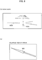
Fig. 8] Fig. 8 is a view for explaining a display example of arrows in the vehicular display device according to Embodiment 1 of the present invention. - [
Fig. 9] Fig. 9 is a view for explaining another display example of arrows in the vehicular display device according to Embodiment 1 of the present invention. - [
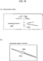
Fig. 10] Fig. 10 is a view for explaining yet another display example of arrows in the vehicular display device according to Embodiment 1 of the present invention. - [
Fig. 11] Fig. 11 is a view for explaining a display example of arrows in a vehicular display device according to Embodiment 2 of the present invention. - A vehicular display device according to embodiments of the present invention is described below in detail with reference to the drawings.
-
Fig. 1 is a diagram illustrating a configuration of a vehicular display device according to Embodiment 1 of the present invention. The vehicular display device displays a guide route to a destination of a host vehicle. The vehicular display device includes a GPS (Global Positioning System)antenna 11, ageomagnetic sensor 12, anavigation device 13, aviewpoint detection camera 14, a viewpoint position determiner 15, adisplay controller 16, and adisplay 17. - The
GPS antenna 11 receives GPS signals from not-illustrated GPS satellites and outputs the received GPS signals to thenavigation device 13 as GPS information. Thegeomagnetic sensor 12 detects azimuth of the direction in which the vehicle is facing (azimuth of the traveling direction of the vehicle) and outputs the detected azimuth to thenavigation device 13 as azimuth information. - The
navigation device 13 calculates the guide route by using the GPS information from theGPS antenna 11, the azimuth information from thegeomagnetic sensor 12, and information acquired in itself. Thenavigation device 13 generates guidance route information for performing guidance along the calculated route and outputs the guide route information to thedisplay controller 16. Details of thenavigation device 13 are described later. - The
viewpoint detection camera 14 captures an image including the positions of the eyes of a driver and outputs the captured image to the viewpoint position determiner 15 as viewpoint image information. - The viewpoint position determiner 15 determines a viewpoint position of the driver based on the viewpoint image information sent from the
viewpoint detection camera 14 and outputs the determination result to thedisplay controller 16 as viewpoint position information. - The
display controller 16 generates an image to be displayed on thedisplay 17 based on the guide route information and the like sent from thenavigation device 13 and the viewpoint position information sent from the viewpoint position determiner 15. Thedisplay controller 16 draws arrows each having a shaft with an arrowhead at one end of the shaft, as guide figures for guidance along the guide route calculated by thenavigation device 13, such that each arrow looks like a three-dimensional object in which a portion of the arrow with a large width has a large height and a portion of the arrow with a small width has a small height. - The
display 17 includes a projection unit which projects a video, a screen and a Fresnel mirror which reflect the video, and the like, and displays an image in a display area provided to overlap the position of a windshield included in the vehicle. Particularly, thedisplay 17 is a head-up display which can display the image in a manner superimposed on a forward view ahead of the vehicle by displaying the image reflected by a mirror, on a near side of the windshield as a virtual image. However, thedisplay 17 is not limited to this type of head-up display. For example, thedisplay 17 may be a combiner type head-up display using a transparent panel instead of displaying the image on the windshield or may employ a method of directly displaying the image on the windshield. In other words, the head-up display in the embodiment may be any type as long as the driver can see the information, displayed by the head-up display in a manner superimposed on a view seen by the driver from the windshield, without looking down. The image based on the display image information generated by thedisplay controller 16 is thereby displayed within the field of view of a person. - Next, the details of the
aforementioned navigation device 13 are described. Thenavigation device 13 includesintersection data 21,map data 22, anacceleration sensor 23, agyroscope sensor 24, and acalculator 25. - The
intersection data 21 is data indicating characteristics and the like of each intersection and is acquired from, for example, a disc device or a center via a communication line and a communication device (both are not illustrated). The intersection data is read by thecalculator 25. - The
map data 22 is data acquired from, for example, the disc device or the center via the communication line and the communication device like theintersection data 21, and is used for drawing of a map, calculation of the guide route, generation of the guide route information to be outputted to thedisplay controller 16, and the like. Themap data 22 is read by thecalculator 25. - The
acceleration sensor 23 detects the acceleration of the host vehicle and outputs the detected acceleration to thecalculator 25 as acceleration information. - The
gyroscope sensor 24 detects the angular velocity of the host vehicle and outputs the detected angular velocity to thecalculator 25 as angular velocity information. - The
calculator 25 calculates the current position of the host vehicle by using themap data 22 and the GPS information sent from theGPS antenna 11. In the calculation, the vehicle sometimes cannot receive the GPS signals when traveling, for example, in a tunnel, under an elevated road, or between tall buildings. Accordingly, thecalculator 25 calculates the current position by autonomous navigation based on themap data 22, the azimuth information from thegeomagnetic sensor 12, the acceleration information from theacceleration sensor 23, and the angular velocity information from thegyroscope sensor 24. Thecalculator 25 creates the guide route information based on the calculated current position and outputs the created guide route information to thedisplay controller 16. - Next, an operation of the vehicular display device according to Embodiment 1 of the present invention configured as described above is described with reference to the flowchart illustrated in
Fig. 2 . Note that the vehicular display device creates arrows (route guide arrows) to be displayed to appear in a manner superimposed on a ground as illustrated in, for example,Fig. 3 for route guidance. - When the operation is started, a guidance flag is first acquired (step S11). Specifically, the
display controller 16 acquires the guidance flag from thenavigation device 13. Here, the guidance flag is a flag instructing whether to perform the guidance along the guide route or not. The guidance along the guide route using the arrows is performed only when the guidance flag is set to on. - Next, whether the guidance flag is on or not is checked (step S12). Specifically, the
display controller 16 checks whether the guidance flag acquired in step S11 is on or not. When the guidance flag is determined not to be on in step S12, thedisplay controller 16 determines that the guidance is unnecessary, and the processing is terminated. - Meanwhile, when the guidance flag is determined to be on in step S12, next, the guide route information is acquired (step S13). Specifically, the
display controller 16 acquires the start position, the direction, and the length of each arrow from thenavigation device 13 as the guide route information. The guide route information is calculated in advance depending on a route search operation performed by the driver and is stored in thenavigation device 13. - Next, the viewpoint position is acquired (step S14). Specifically, the
display controller 16 acquires the viewpoint position information from theviewpoint position determiner 15. - Then, arrangement of arrows drawn by lines in the display area is calculated (step S15). Specifically, the
display controller 16 arranges arrows drawn by lines in a manner superimposed on the guide route as viewed from the driver, by using the guide route information acquired in step S13 and the viewpoint position acquired in step S14. - Next, three-dimensional looking arrows are drawn (step S16). Specifically, the
display controller 16 draws arrows to be displayed in the display area by converting the arrows drawn by lines and arranged in the display area in step S15 to arrows looking three-dimensional as viewed from the viewpoint of the driver indicated by the viewpoint position information acquired in step S14. Steps of drawing the three-dimensional looking arrows are described in detail later. - Next, a display image is outputted to the display 17 (step S17). Specifically, the
display controller 16 outputs the image drawn in step S16 to thedisplay 17 as display image information. Thedisplay 17 thereby generates an image based on the display image information from thedisplay controller 16, displays the generated image on a liquid crystal display or the like, and causes the image to be reflected on a mirror or the windshield to display the image directly within the field of view of a person. Thereafter, the sequence returns to step S12 and the aforementioned processes are repeated. - Specifically, as illustrated in
Fig. 3 , three-dimensional looking arrows M30a, M30b, M30c, M30d, and M30e are displayed in a manner superimposed on the guide route in the display area provided to overlap an outside view ahead of the windshield. - Next, the steps of drawing each of the three-dimensional looking arrows are described.
-
- (1) First, as illustrated in part (a) of
Fig. 4 , start point coordinates ST of an arrow are acquired from thenavigation device 13. - (2) Then, as illustrated in part (b) of
Fig. 4 , information indicating the direction and length of the arrow L1 is acquired. - (3) Next, as illustrated in part (c) of
Fig. 4 , the thickness of the arrow L1 drawn by lines defined by the start point coordinates ST in (1) and the information indicating the direction and length in (2) is increased in a planar direction to create a two-dimensional arrow M20. - (4) Then, as illustrated in part (d) of
Fig. 4 , the thickness of the two-dimensional arrow M20 created in (3) is increased to create a three-dimensional looking arrow M30. In this case, the arrow M30 is processed to look like a three-dimensional object in which a portion of the arrow M30 with a large width of w2 has a large height h2 and a portion of the arrow M30 with a small width of wl has a small height h1. -
Figs. 5 to 7 are views for explaining display examples of arrows in existing vehicular display devices and, in each view, arrows of the same pattern (including multiple arrows) are drawn on the ground to be arranged in traveling directions of the vehicle. In the display of flat arrows drawn on the ground, as illustrated inFig. 5 , the larger the distance to an arrow M21 is, the smaller the arrow M21 is. Moreover, the distant arrows are viewed at angles close to an edge-on angle and a vertical arrow M21v has a small dimension and is hard to read. This is particularly significant for a horizontal arrow M21h. - One may try to improve this by using arrows M22 each with an increased width as illustrated in
Fig. 6 . However, there is no significant improvement in readability. Moreover, arrows M23 which are three-dimensional objects each with a certain thickness can be used to improve the noticeability of distant horizontal arrows M23h. In this case, the distant horizontal arrows M23h are noticeable, but it is hard to read the direction in which each arrow is pointing. - Meanwhile, in the vehicular display device according to Embodiment 1, as illustrated in
Fig. 8 , since each of arrows M33 is displayed to look like a three-dimensional arch-shaped object in which a portion of the arrow with a large width has a large height and a portion of the arrow with a small width has a small height, the direction in which the arrow is pointing is easy to read. Moreover, since the shape of an arrowhead in each of distant horizontal arrows M33h is easy to read, the direction in which the arrow is pointing is easy to read. - Although the arrows are drawn in the three-dimensional arch shape which is raised in the center portion in the width direction as in the example illustrated in
Fig. 8 , the arrows may be drawn like arrows M34 with a three-dimensional ridge shape which is bent at the center in the width direction as illustrated inFig. 9 . Moreover, as illustrated inFig. 10 , the arrows may be each drawn to look like a three-dimensional cockscomb-shaped object whose height changes only in a center portion M35b in the width direction. - A configuration of a vehicular display device according to Embodiment 2 of the present invention is the same as the configuration of the vehicular display device according to Embodiment 1 illustrated in
Fig. 1 , and is different only in the shape of the arrows displayed in thedisplay 17. Accordingly, description is given below mainly of portions different from Embodiment 1. - In some cases, the
navigation device 13 sends the display controller 16 a line configured by a straight line and a curved line as one mode of the guide route information. - Next, an operation of the vehicular display device according to Embodiment 2 of the present invention is described with reference to the flowchart illustrated in
Fig. 2 used for the description of the operation in the vehicular display device according to Embodiment 1. - Since processes in step S11 to S12 are the same as those in the flowchart illustrated in
Fig. 2 , description thereof is omitted. - In step S13, assume that the guide route indicated by the guide route information acquired from the
navigation device 13 indicates "left turn" at the next intersection. In this case, thedisplay controller 16 acquires a guide route curved to the left from thenavigation device 13. - Next, the viewpoint position is acquired (step S14). Specifically, the
display controller 16 acquires the viewpoint position information from theviewpoint position determiner 15. - Then, arrangement of an arrow drawn by lines in the display area is calculated (step S15). Specifically, the
display controller 16 arranges a curved arrow drawn by lines in a manner superimposed on the guide route as viewed from the driver, by using the information on the guide route curved to the left which is acquired in step S13 and the viewpoint position which is acquired in step S14. - Next, the arrow is drawn to look three-dimensional (step S16). Then, the display image is outputted to the display (step S17). The
display 17 thereby generates an image based on the display image information from thedisplay controller 16, displays the generated image on the liquid crystal display or the like, and causes the image to be reflected on the mirror or the windshield to display the image directly within the field of view of a person. Thereafter, the sequence returns to step S12 and the aforementioned processes are repeated. - By the aforementioned operation, the
display 17 displays an arrow instructing a left turn at the next intersection, for example, an arrow M33A having a shaft curved to the left as illustrated inFig. 11 . The arrow M33A is configured by an arrow M33a having a shape of an arrowhead, a linear arrow M33b connected to the arrow M33a, and an arrow M33c bent relative to the arrow M33b. - In the vehicular display device according to Embodiment 2 of the present invention, since the arrow used for guidance in an intersection is displayed as an arrow looking like a three-dimensional arch-shaped object in which a portion of the arrow with a large width has a large height and a portion of the arrow with a small width has a small height, the direction in which the arrow is pointing is easy to read. Moreover, since the shape of the arrowhead in the distant horizontal arrow is easy to read, the direction in which the arrow is pointing is easy to read.
- Note that, in the example illustrated in
Fig 11 , although the arrow is drawn to look like the three-dimensional arch-shaped object, the arrow may be drawn to look like a three-dimensional ridge-shaped object which is bent at the center in the width direction as in Embodiment 1. Moreover, the arrow may be drawn to look like a three-dimensional cockscomb-shaped object whose height changes only in a center portion in the width direction. -
- 11
- GPS antenna
- 12
- geomagnetic sensor
- 13
- navigation device
- 14
- viewpoint detection camera
- 15
- viewpoint position determiner
- 16
- display controller
- 17
- display
- 21
- intersection data
- 22
- map data
- 23
- acceleration sensor
- 24
- gyroscope sensor
- 25
- calculator
Claims (4)
- A vehicular display device configured to display a guide route to a destination of a host vehicle, the vehicular display device comprising:a navigation device configured to calculate the guide route;a display controller configured to draw an arrow having a shaft with an arrowhead at one end of the shaft, as a guide figure for guidance along the guide route calculated by the navigation device, such that the arrow looks like a three-dimensional object in which a portion of the arrow with a large width has a large height and a portion of the arrow with a small width has a small height; anda display configured to display an image drawn by the display controller in a display area provided to overlap a position of a windshield.
- The vehicular display device according to claim 1, wherein the display controller is configured to draw the arrow in a three-dimensional arch shape which is raised in a center portion in a width direction.
- The vehicular display device according to claim 1, wherein the display controller is configured to draw the arrow in a three-dimensional ridge shape which is bent at a center in a width direction.
- The vehicular display device according to claim 1, wherein the display controller is configured to draw the arrow in a three-dimensional cockscomb shape only a center portion of which in a width direction is protruded to have a height.
Applications Claiming Priority (1)
| Application Number | Priority Date | Filing Date | Title |
|---|---|---|---|
| PCT/JP2015/077667 WO2017056211A1 (en) | 2015-09-30 | 2015-09-30 | Vehicular display device |
Publications (3)
| Publication Number | Publication Date |
|---|---|
| EP3358305A1 true EP3358305A1 (en) | 2018-08-08 |
| EP3358305A4 EP3358305A4 (en) | 2019-02-27 |
| EP3358305B1 EP3358305B1 (en) | 2021-07-07 |
Family
ID=58423137
Family Applications (1)
| Application Number | Title | Priority Date | Filing Date |
|---|---|---|---|
| EP15905365.1A Active EP3358305B1 (en) | 2015-09-30 | 2015-09-30 | Vehicular display device |
Country Status (10)
| Country | Link |
|---|---|
| US (1) | US11209285B2 (en) |
| EP (1) | EP3358305B1 (en) |
| JP (1) | JP6536856B2 (en) |
| KR (1) | KR20180044993A (en) |
| CN (1) | CN108139223A (en) |
| BR (1) | BR112018006613B1 (en) |
| CA (1) | CA2999955C (en) |
| MX (1) | MX387053B (en) |
| RU (1) | RU2677999C1 (en) |
| WO (1) | WO2017056211A1 (en) |
Cited By (2)
| Publication number | Priority date | Publication date | Assignee | Title |
|---|---|---|---|---|
| US20220026231A1 (en) * | 2019-04-10 | 2022-01-27 | Beijing Didi Infinity Technology And Development Co., Ltd. | Display methods and systems for indicator arrow in navigation map |
| EP4040113A3 (en) * | 2021-06-28 | 2023-01-11 | Apollo Intelligent Connectivity (Beijing) Technology Co., Ltd. | Method and apparatus for road guidance, and electronic device |
Families Citing this family (17)
| Publication number | Priority date | Publication date | Assignee | Title |
|---|---|---|---|---|
| US11307420B2 (en) | 2017-07-03 | 2022-04-19 | Holovisions LLC | Augmented reality eyewear with “ghost buster” technology |
| US12601923B2 (en) | 2017-07-03 | 2026-04-14 | Holovisions LLC | Augmented reality (AR) eyewear with an environment-only viewing mode and an augmented reality viewing mode |
| US11754843B2 (en) | 2017-07-03 | 2023-09-12 | Holovisions LLC | Augmented reality eyewear with “ghost buster” technology |
| US11163163B2 (en) | 2017-07-03 | 2021-11-02 | Holovisions | Augmented reality (AR) eyewear with at least one quasi Fresnel reflector (QFR) |
| US12436394B2 (en) | 2017-07-03 | 2025-10-07 | Holovisions | Augmented reality (or mixed reality) eyewear with see-through optical elements having individually-adjustable opacity/reflectivity levels |
| US12013538B2 (en) | 2017-07-03 | 2024-06-18 | Holovisions LLC | Augmented reality (AR) eyewear with a section of a fresnel reflector comprising individually-adjustable transmissive-reflective optical elements |
| US12205231B2 (en) | 2017-07-03 | 2025-01-21 | Holovisions | Holovisions™—adjustable and/or modular augmented reality (AR) eyewear with a movable transflective mirror and different viewing modes |
| KR102547823B1 (en) * | 2017-12-13 | 2023-06-26 | 삼성전자주식회사 | Method and device to visualize content |
| JP6938367B2 (en) * | 2017-12-28 | 2021-09-22 | アルパイン株式会社 | In-vehicle system |
| CN108896066A (en) * | 2018-03-23 | 2018-11-27 | 江苏泽景汽车电子股份有限公司 | A kind of augmented reality head up display and its navigation implementation method |
| JP2019182190A (en) * | 2018-04-10 | 2019-10-24 | 株式会社デンソー | Image control device |
| JP7172247B2 (en) * | 2018-07-26 | 2022-11-16 | トヨタ自動車株式会社 | DISPLAY CONTROL DEVICE, VEHICLE DISPLAY DEVICE, DISPLAY CONTROL METHOD AND PROGRAM |
| CN111152721B (en) * | 2019-12-31 | 2022-09-02 | 合肥疆程技术有限公司 | Method and device for drawing guide line of lane and head-up display system |
| KR102862959B1 (en) * | 2020-01-02 | 2025-09-22 | 삼성전자 주식회사 | Apparatus and method for displaying navigation information of three dimention augmented reality |
| JP7585754B2 (en) * | 2020-01-24 | 2024-11-19 | 株式会社リコー | Display device, mobile object, display method, and program |
| JP7746925B2 (en) * | 2022-06-16 | 2025-10-01 | トヨタ自動車株式会社 | Display control device, display device, display system, vehicle, display control method and program |
| CN116558542B (en) * | 2023-03-28 | 2025-09-05 | 阿里巴巴(中国)有限公司 | Guide arrow generation method, device, equipment and product |
Family Cites Families (29)
| Publication number | Priority date | Publication date | Assignee | Title |
|---|---|---|---|---|
| JP3708221B2 (en) * | 1996-06-05 | 2005-10-19 | 松下電器産業株式会社 | Traveling position display device |
| US6611753B1 (en) * | 1998-04-17 | 2003-08-26 | Magellan Dis, Inc. | 3-dimensional intersection display for vehicle navigation system |
| US6144382A (en) * | 1998-09-30 | 2000-11-07 | Autodesk, Inc. | Three-dimensional arrow for computer graphics |
| US6327364B1 (en) * | 1998-12-15 | 2001-12-04 | Siemens Information And Communication Networks, Inc. | Reducing resource consumption by ACD systems |
| US6883145B2 (en) * | 2001-02-15 | 2005-04-19 | Denny Jaeger | Arrow logic system for creating and operating control systems |
| US6836725B2 (en) * | 2001-09-27 | 2004-12-28 | Magellan Dis, Inc. | Vehicle navigation system with off-road navigation |
| DE10354218A1 (en) * | 2003-11-20 | 2005-06-30 | Siemens Ag | Method for selecting and preparing traffic information |
| JP2007225628A (en) * | 2004-03-31 | 2007-09-06 | Pioneer Electronic Corp | Map creation device |
| US7932909B2 (en) * | 2004-04-16 | 2011-04-26 | Apple Inc. | User interface for controlling three-dimensional animation of an object |
| JP4632793B2 (en) * | 2005-01-12 | 2011-02-16 | 京セラ株式会社 | Portable terminal with navigation function |
| WO2007142084A1 (en) | 2006-06-05 | 2007-12-13 | Panasonic Corporation | Navigation device |
| JP4560090B2 (en) | 2006-06-12 | 2010-10-13 | パナソニック株式会社 | Navigation device and navigation method |
| JP5087750B2 (en) * | 2007-04-27 | 2012-12-05 | 建次 竹永 | Directional presentation board, operation direction guide for rotating transparent door |
| JP2010127685A (en) * | 2008-11-26 | 2010-06-10 | Honda Motor Co Ltd | Navigation apparatus |
| JP5161760B2 (en) | 2008-12-26 | 2013-03-13 | 株式会社東芝 | In-vehicle display system and display method |
| KR101392728B1 (en) | 2009-02-06 | 2014-05-08 | 팅크웨어(주) | Method and apparatus for creating of 3d direction dispalying |
| JP4461190B1 (en) * | 2009-02-24 | 2010-05-12 | 株式会社東芝 | Electronic device and navigation image display method |
| EP2244242A1 (en) * | 2009-04-23 | 2010-10-27 | Wayfinder Systems AB | Method and device for improved navigation |
| CN201402141Y (en) * | 2009-04-27 | 2010-02-10 | 江苏新科软件有限公司 | Navigation device taking 3D arrowhead as intersection turning informatory sign |
| JP2012110490A (en) | 2010-11-24 | 2012-06-14 | Olympus Corp | Endoscope apparatus |
| US8591401B2 (en) | 2010-08-18 | 2013-11-26 | Olympus Corporation | Endoscope apparatus displaying information indicating gravity direction on screen |
| DE102010040803A1 (en) | 2010-09-15 | 2012-03-15 | Continental Teves Ag & Co. Ohg | Visual driver information and warning system for a driver of a motor vehicle |
| US8886530B2 (en) * | 2011-06-24 | 2014-11-11 | Honda Motor Co., Ltd. | Displaying text and direction of an utterance combined with an image of a sound source |
| JP2014071627A (en) * | 2012-09-28 | 2014-04-21 | Aisin Aw Co Ltd | Driving condition display system, driving condition display program, and driving condition display method |
| US8928666B2 (en) * | 2012-10-11 | 2015-01-06 | Google Inc. | Navigating visual data associated with a point of interest |
| JP2014185926A (en) * | 2013-03-22 | 2014-10-02 | Aisin Aw Co Ltd | Guidance display system |
| GB201318049D0 (en) | 2013-10-11 | 2013-11-27 | Tomtom Int Bv | Apparatus and methods of displaying navigation instructions |
| KR102071693B1 (en) | 2014-02-07 | 2020-01-30 | 엘지전자 주식회사 | Head-Up Display Apparatus |
| US20160328887A1 (en) * | 2015-05-04 | 2016-11-10 | The Trustees Of Columbia University In The City Of New York | Systems and methods for providing assistance for manipulating objects using virtual proxies and virtual replicas |
-
2015
- 2015-09-30 CA CA2999955A patent/CA2999955C/en active Active
- 2015-09-30 WO PCT/JP2015/077667 patent/WO2017056211A1/en not_active Ceased
- 2015-09-30 CN CN201580083470.1A patent/CN108139223A/en active Pending
- 2015-09-30 BR BR112018006613-3A patent/BR112018006613B1/en active IP Right Grant
- 2015-09-30 KR KR1020187008790A patent/KR20180044993A/en not_active Ceased
- 2015-09-30 RU RU2018116011A patent/RU2677999C1/en active
- 2015-09-30 MX MX2018003817A patent/MX387053B/en unknown
- 2015-09-30 EP EP15905365.1A patent/EP3358305B1/en active Active
- 2015-09-30 US US15/764,778 patent/US11209285B2/en active Active
- 2015-09-30 JP JP2017542572A patent/JP6536856B2/en active Active
Cited By (2)
| Publication number | Priority date | Publication date | Assignee | Title |
|---|---|---|---|---|
| US20220026231A1 (en) * | 2019-04-10 | 2022-01-27 | Beijing Didi Infinity Technology And Development Co., Ltd. | Display methods and systems for indicator arrow in navigation map |
| EP4040113A3 (en) * | 2021-06-28 | 2023-01-11 | Apollo Intelligent Connectivity (Beijing) Technology Co., Ltd. | Method and apparatus for road guidance, and electronic device |
Also Published As
| Publication number | Publication date |
|---|---|
| BR112018006613A2 (en) | 2018-10-23 |
| RU2677999C1 (en) | 2019-01-22 |
| MX387053B (en) | 2025-03-19 |
| CA2999955C (en) | 2019-04-30 |
| US11209285B2 (en) | 2021-12-28 |
| WO2017056211A1 (en) | 2017-04-06 |
| EP3358305B1 (en) | 2021-07-07 |
| MX2018003817A (en) | 2018-06-18 |
| CN108139223A (en) | 2018-06-08 |
| BR112018006613B1 (en) | 2022-10-18 |
| JP6536856B2 (en) | 2019-07-03 |
| CA2999955A1 (en) | 2017-04-06 |
| US20190041232A1 (en) | 2019-02-07 |
| KR20180044993A (en) | 2018-05-03 |
| JPWO2017056211A1 (en) | 2018-09-13 |
| EP3358305A4 (en) | 2019-02-27 |
Similar Documents
| Publication | Publication Date | Title |
|---|---|---|
| EP3358305B1 (en) | Vehicular display device | |
| US10466062B2 (en) | Vehicular display device | |
| CN113063418B (en) | Method and device for displaying 3D augmented reality navigation information | |
| US11249308B2 (en) | Display device in moving body for displaying superimposed virtual image and display control method | |
| US8395490B2 (en) | Blind spot display apparatus | |
| JP6775188B2 (en) | Head-up display device and display control method | |
| JP6176541B2 (en) | Information display device, information display method, and program | |
| US10895912B2 (en) | Apparatus and a method for controlling a head- up display of a vehicle | |
| JP2008309529A (en) | NAVIGATION DEVICE, NAVIGATION METHOD, AND NAVIGATION PROGRAM | |
| JP2009020089A (en) | NAVIGATION DEVICE, NAVIGATION METHOD, AND NAVIGATION PROGRAM | |
| JP2016074410A (en) | Head-up display device and head-up display display method | |
| JP6444508B2 (en) | Display control device and navigation device | |
| CN102538799B (en) | For the method and apparatus of display section surrounding environment | |
| JP2019105581A (en) | Navigation device | |
| JP2010187413A (en) | Vehicle display apparatus | |
| JPWO2017163385A1 (en) | Support image display device, support image display method, and support image display program | |
| KR101637298B1 (en) | Head-up display apparatus for vehicle using aumented reality | |
| US12612106B2 (en) | Driving assistance system, driving assistance method, and recording medium |
Legal Events
| Date | Code | Title | Description |
|---|---|---|---|
| STAA | Information on the status of an ep patent application or granted ep patent |
Free format text: STATUS: THE INTERNATIONAL PUBLICATION HAS BEEN MADE |
|
| PUAI | Public reference made under article 153(3) epc to a published international application that has entered the european phase |
Free format text: ORIGINAL CODE: 0009012 |
|
| STAA | Information on the status of an ep patent application or granted ep patent |
Free format text: STATUS: REQUEST FOR EXAMINATION WAS MADE |
|
| 17P | Request for examination filed |
Effective date: 20180426 |
|
| AK | Designated contracting states |
Kind code of ref document: A1 Designated state(s): AL AT BE BG CH CY CZ DE DK EE ES FI FR GB GR HR HU IE IS IT LI LT LU LV MC MK MT NL NO PL PT RO RS SE SI SK SM TR |
|
| AX | Request for extension of the european patent |
Extension state: BA ME |
|
| DAV | Request for validation of the european patent (deleted) | ||
| DAX | Request for extension of the european patent (deleted) | ||
| A4 | Supplementary search report drawn up and despatched |
Effective date: 20190130 |
|
| RIC1 | Information provided on ipc code assigned before grant |
Ipc: B60K 35/00 20060101ALI20190124BHEP Ipc: G01C 21/36 20060101AFI20190124BHEP Ipc: G01C 21/26 20060101ALI20190124BHEP |
|
| STAA | Information on the status of an ep patent application or granted ep patent |
Free format text: STATUS: EXAMINATION IS IN PROGRESS |
|
| 17Q | First examination report despatched |
Effective date: 20190919 |
|
| GRAP | Despatch of communication of intention to grant a patent |
Free format text: ORIGINAL CODE: EPIDOSNIGR1 |
|
| STAA | Information on the status of an ep patent application or granted ep patent |
Free format text: STATUS: GRANT OF PATENT IS INTENDED |
|
| INTG | Intention to grant announced |
Effective date: 20200318 |
|
| RIN1 | Information on inventor provided before grant (corrected) |
Inventor name: MARUYAMA, KENJI Inventor name: KOSAKA, NORIO Inventor name: WATANABE, HIROSHI Inventor name: SHISHIDO, MASAYUKI |
|
| GRAJ | Information related to disapproval of communication of intention to grant by the applicant or resumption of examination proceedings by the epo deleted |
Free format text: ORIGINAL CODE: EPIDOSDIGR1 |
|
| STAA | Information on the status of an ep patent application or granted ep patent |
Free format text: STATUS: EXAMINATION IS IN PROGRESS |
|
| INTC | Intention to grant announced (deleted) | ||
| GRAP | Despatch of communication of intention to grant a patent |
Free format text: ORIGINAL CODE: EPIDOSNIGR1 |
|
| STAA | Information on the status of an ep patent application or granted ep patent |
Free format text: STATUS: GRANT OF PATENT IS INTENDED |
|
| INTG | Intention to grant announced |
Effective date: 20210315 |
|
| RIN1 | Information on inventor provided before grant (corrected) |
Inventor name: MARUYAMA, KENJI Inventor name: SHISHIDO, MASAYUKI Inventor name: WATANABE, HIROSHI Inventor name: KOSAKA, NORIO |
|
| GRAS | Grant fee paid |
Free format text: ORIGINAL CODE: EPIDOSNIGR3 |
|
| GRAA | (expected) grant |
Free format text: ORIGINAL CODE: 0009210 |
|
| STAA | Information on the status of an ep patent application or granted ep patent |
Free format text: STATUS: THE PATENT HAS BEEN GRANTED |
|
| AK | Designated contracting states |
Kind code of ref document: B1 Designated state(s): AL AT BE BG CH CY CZ DE DK EE ES FI FR GB GR HR HU IE IS IT LI LT LU LV MC MK MT NL NO PL PT RO RS SE SI SK SM TR |
|
| REG | Reference to a national code |
Ref country code: GB Ref legal event code: FG4D |
|
| REG | Reference to a national code |
Ref country code: AT Ref legal event code: REF Ref document number: 1409018 Country of ref document: AT Kind code of ref document: T Effective date: 20210715 |
|
| REG | Reference to a national code |
Ref country code: DE Ref legal event code: R096 Ref document number: 602015071216 Country of ref document: DE |
|
| REG | Reference to a national code |
Ref country code: IE Ref legal event code: FG4D |
|
| REG | Reference to a national code |
Ref country code: LT Ref legal event code: MG9D |
|
| REG | Reference to a national code |
Ref country code: NL Ref legal event code: MP Effective date: 20210707 |
|
| REG | Reference to a national code |
Ref country code: AT Ref legal event code: MK05 Ref document number: 1409018 Country of ref document: AT Kind code of ref document: T Effective date: 20210707 |
|
| PG25 | Lapsed in a contracting state [announced via postgrant information from national office to epo] |
Ref country code: HR Free format text: LAPSE BECAUSE OF FAILURE TO SUBMIT A TRANSLATION OF THE DESCRIPTION OR TO PAY THE FEE WITHIN THE PRESCRIBED TIME-LIMIT Effective date: 20210707 Ref country code: RS Free format text: LAPSE BECAUSE OF FAILURE TO SUBMIT A TRANSLATION OF THE DESCRIPTION OR TO PAY THE FEE WITHIN THE PRESCRIBED TIME-LIMIT Effective date: 20210707 Ref country code: SE Free format text: LAPSE BECAUSE OF FAILURE TO SUBMIT A TRANSLATION OF THE DESCRIPTION OR TO PAY THE FEE WITHIN THE PRESCRIBED TIME-LIMIT Effective date: 20210707 Ref country code: LT Free format text: LAPSE BECAUSE OF FAILURE TO SUBMIT A TRANSLATION OF THE DESCRIPTION OR TO PAY THE FEE WITHIN THE PRESCRIBED TIME-LIMIT Effective date: 20210707 Ref country code: AT Free format text: LAPSE BECAUSE OF FAILURE TO SUBMIT A TRANSLATION OF THE DESCRIPTION OR TO PAY THE FEE WITHIN THE PRESCRIBED TIME-LIMIT Effective date: 20210707 Ref country code: BG Free format text: LAPSE BECAUSE OF FAILURE TO SUBMIT A TRANSLATION OF THE DESCRIPTION OR TO PAY THE FEE WITHIN THE PRESCRIBED TIME-LIMIT Effective date: 20211007 Ref country code: NL Free format text: LAPSE BECAUSE OF FAILURE TO SUBMIT A TRANSLATION OF THE DESCRIPTION OR TO PAY THE FEE WITHIN THE PRESCRIBED TIME-LIMIT Effective date: 20210707 Ref country code: PT Free format text: LAPSE BECAUSE OF FAILURE TO SUBMIT A TRANSLATION OF THE DESCRIPTION OR TO PAY THE FEE WITHIN THE PRESCRIBED TIME-LIMIT Effective date: 20211108 Ref country code: NO Free format text: LAPSE BECAUSE OF FAILURE TO SUBMIT A TRANSLATION OF THE DESCRIPTION OR TO PAY THE FEE WITHIN THE PRESCRIBED TIME-LIMIT Effective date: 20211007 Ref country code: FI Free format text: LAPSE BECAUSE OF FAILURE TO SUBMIT A TRANSLATION OF THE DESCRIPTION OR TO PAY THE FEE WITHIN THE PRESCRIBED TIME-LIMIT Effective date: 20210707 Ref country code: ES Free format text: LAPSE BECAUSE OF FAILURE TO SUBMIT A TRANSLATION OF THE DESCRIPTION OR TO PAY THE FEE WITHIN THE PRESCRIBED TIME-LIMIT Effective date: 20210707 |
|
| PG25 | Lapsed in a contracting state [announced via postgrant information from national office to epo] |
Ref country code: PL Free format text: LAPSE BECAUSE OF FAILURE TO SUBMIT A TRANSLATION OF THE DESCRIPTION OR TO PAY THE FEE WITHIN THE PRESCRIBED TIME-LIMIT Effective date: 20210707 Ref country code: LV Free format text: LAPSE BECAUSE OF FAILURE TO SUBMIT A TRANSLATION OF THE DESCRIPTION OR TO PAY THE FEE WITHIN THE PRESCRIBED TIME-LIMIT Effective date: 20210707 Ref country code: GR Free format text: LAPSE BECAUSE OF FAILURE TO SUBMIT A TRANSLATION OF THE DESCRIPTION OR TO PAY THE FEE WITHIN THE PRESCRIBED TIME-LIMIT Effective date: 20211008 |
|
| REG | Reference to a national code |
Ref country code: DE Ref legal event code: R097 Ref document number: 602015071216 Country of ref document: DE |
|
| PG25 | Lapsed in a contracting state [announced via postgrant information from national office to epo] |
Ref country code: DK Free format text: LAPSE BECAUSE OF FAILURE TO SUBMIT A TRANSLATION OF THE DESCRIPTION OR TO PAY THE FEE WITHIN THE PRESCRIBED TIME-LIMIT Effective date: 20210707 |
|
| REG | Reference to a national code |
Ref country code: CH Ref legal event code: PL |
|
| PLBE | No opposition filed within time limit |
Free format text: ORIGINAL CODE: 0009261 |
|
| STAA | Information on the status of an ep patent application or granted ep patent |
Free format text: STATUS: NO OPPOSITION FILED WITHIN TIME LIMIT |
|
| REG | Reference to a national code |
Ref country code: BE Ref legal event code: MM Effective date: 20210930 |
|
| PG25 | Lapsed in a contracting state [announced via postgrant information from national office to epo] |
Ref country code: SM Free format text: LAPSE BECAUSE OF FAILURE TO SUBMIT A TRANSLATION OF THE DESCRIPTION OR TO PAY THE FEE WITHIN THE PRESCRIBED TIME-LIMIT Effective date: 20210707 Ref country code: SK Free format text: LAPSE BECAUSE OF FAILURE TO SUBMIT A TRANSLATION OF THE DESCRIPTION OR TO PAY THE FEE WITHIN THE PRESCRIBED TIME-LIMIT Effective date: 20210707 Ref country code: RO Free format text: LAPSE BECAUSE OF FAILURE TO SUBMIT A TRANSLATION OF THE DESCRIPTION OR TO PAY THE FEE WITHIN THE PRESCRIBED TIME-LIMIT Effective date: 20210707 Ref country code: MC Free format text: LAPSE BECAUSE OF FAILURE TO SUBMIT A TRANSLATION OF THE DESCRIPTION OR TO PAY THE FEE WITHIN THE PRESCRIBED TIME-LIMIT Effective date: 20210707 Ref country code: EE Free format text: LAPSE BECAUSE OF FAILURE TO SUBMIT A TRANSLATION OF THE DESCRIPTION OR TO PAY THE FEE WITHIN THE PRESCRIBED TIME-LIMIT Effective date: 20210707 Ref country code: CZ Free format text: LAPSE BECAUSE OF FAILURE TO SUBMIT A TRANSLATION OF THE DESCRIPTION OR TO PAY THE FEE WITHIN THE PRESCRIBED TIME-LIMIT Effective date: 20210707 Ref country code: AL Free format text: LAPSE BECAUSE OF FAILURE TO SUBMIT A TRANSLATION OF THE DESCRIPTION OR TO PAY THE FEE WITHIN THE PRESCRIBED TIME-LIMIT Effective date: 20210707 |
|
| 26N | No opposition filed |
Effective date: 20220408 |
|
| PG25 | Lapsed in a contracting state [announced via postgrant information from national office to epo] |
Ref country code: LU Free format text: LAPSE BECAUSE OF NON-PAYMENT OF DUE FEES Effective date: 20210930 Ref country code: IT Free format text: LAPSE BECAUSE OF FAILURE TO SUBMIT A TRANSLATION OF THE DESCRIPTION OR TO PAY THE FEE WITHIN THE PRESCRIBED TIME-LIMIT Effective date: 20210707 Ref country code: IE Free format text: LAPSE BECAUSE OF NON-PAYMENT OF DUE FEES Effective date: 20210930 Ref country code: BE Free format text: LAPSE BECAUSE OF NON-PAYMENT OF DUE FEES Effective date: 20210930 |
|
| PG25 | Lapsed in a contracting state [announced via postgrant information from national office to epo] |
Ref country code: LI Free format text: LAPSE BECAUSE OF NON-PAYMENT OF DUE FEES Effective date: 20210930 Ref country code: CH Free format text: LAPSE BECAUSE OF NON-PAYMENT OF DUE FEES Effective date: 20210930 |
|
| PG25 | Lapsed in a contracting state [announced via postgrant information from national office to epo] |
Ref country code: CY Free format text: LAPSE BECAUSE OF FAILURE TO SUBMIT A TRANSLATION OF THE DESCRIPTION OR TO PAY THE FEE WITHIN THE PRESCRIBED TIME-LIMIT Effective date: 20210707 |
|
| PG25 | Lapsed in a contracting state [announced via postgrant information from national office to epo] |
Ref country code: HU Free format text: LAPSE BECAUSE OF FAILURE TO SUBMIT A TRANSLATION OF THE DESCRIPTION OR TO PAY THE FEE WITHIN THE PRESCRIBED TIME-LIMIT; INVALID AB INITIO Effective date: 20150930 |
|
| REG | Reference to a national code |
Ref country code: DE Ref legal event code: R084 Ref document number: 602015071216 Country of ref document: DE |
|
| REG | Reference to a national code |
Ref country code: GB Ref legal event code: 746 Effective date: 20230926 |
|
| PG25 | Lapsed in a contracting state [announced via postgrant information from national office to epo] |
Ref country code: MK Free format text: LAPSE BECAUSE OF FAILURE TO SUBMIT A TRANSLATION OF THE DESCRIPTION OR TO PAY THE FEE WITHIN THE PRESCRIBED TIME-LIMIT Effective date: 20210707 |
|
| PG25 | Lapsed in a contracting state [announced via postgrant information from national office to epo] |
Ref country code: TR Free format text: LAPSE BECAUSE OF FAILURE TO SUBMIT A TRANSLATION OF THE DESCRIPTION OR TO PAY THE FEE WITHIN THE PRESCRIBED TIME-LIMIT Effective date: 20210707 |
|
| PG25 | Lapsed in a contracting state [announced via postgrant information from national office to epo] |
Ref country code: MT Free format text: LAPSE BECAUSE OF FAILURE TO SUBMIT A TRANSLATION OF THE DESCRIPTION OR TO PAY THE FEE WITHIN THE PRESCRIBED TIME-LIMIT Effective date: 20210707 |
|
| PGFP | Annual fee paid to national office [announced via postgrant information from national office to epo] |
Ref country code: DE Payment date: 20250820 Year of fee payment: 11 |
|
| PGFP | Annual fee paid to national office [announced via postgrant information from national office to epo] |
Ref country code: GB Payment date: 20250822 Year of fee payment: 11 |
|
| PGFP | Annual fee paid to national office [announced via postgrant information from national office to epo] |
Ref country code: FR Payment date: 20250821 Year of fee payment: 11 |