EP3358303A1 - An apparatus and associated methods for use in updating map data - Google Patents
An apparatus and associated methods for use in updating map data Download PDFInfo
- Publication number
- EP3358303A1 EP3358303A1 EP17154967.8A EP17154967A EP3358303A1 EP 3358303 A1 EP3358303 A1 EP 3358303A1 EP 17154967 A EP17154967 A EP 17154967A EP 3358303 A1 EP3358303 A1 EP 3358303A1
- Authority
- EP
- European Patent Office
- Prior art keywords
- anomalies
- map data
- road network
- errors
- predefined map
- Prior art date
- Legal status (The legal status is an assumption and is not a legal conclusion. Google has not performed a legal analysis and makes no representation as to the accuracy of the status listed.)
- Granted
Links
Images




Classifications
-
- G—PHYSICS
- G01—MEASURING; TESTING
- G01C—MEASURING DISTANCES, LEVELS OR BEARINGS; SURVEYING; NAVIGATION; GYROSCOPIC INSTRUMENTS; PHOTOGRAMMETRY OR VIDEOGRAMMETRY
- G01C21/00—Navigation; Navigational instruments not provided for in groups G01C1/00 - G01C19/00
- G01C21/38—Electronic maps specially adapted for navigation; Updating thereof
- G01C21/3804—Creation or updating of map data
- G01C21/3807—Creation or updating of map data characterised by the type of data
- G01C21/3815—Road data
- G01C21/3819—Road shape data, e.g. outline of a route
-
- G—PHYSICS
- G01—MEASURING; TESTING
- G01C—MEASURING DISTANCES, LEVELS OR BEARINGS; SURVEYING; NAVIGATION; GYROSCOPIC INSTRUMENTS; PHOTOGRAMMETRY OR VIDEOGRAMMETRY
- G01C21/00—Navigation; Navigational instruments not provided for in groups G01C1/00 - G01C19/00
- G01C21/38—Electronic maps specially adapted for navigation; Updating thereof
- G01C21/3804—Creation or updating of map data
- G01C21/3859—Differential updating map data
-
- G—PHYSICS
- G01—MEASURING; TESTING
- G01C—MEASURING DISTANCES, LEVELS OR BEARINGS; SURVEYING; NAVIGATION; GYROSCOPIC INSTRUMENTS; PHOTOGRAMMETRY OR VIDEOGRAMMETRY
- G01C21/00—Navigation; Navigational instruments not provided for in groups G01C1/00 - G01C19/00
- G01C21/38—Electronic maps specially adapted for navigation; Updating thereof
- G01C21/3804—Creation or updating of map data
- G01C21/3807—Creation or updating of map data characterised by the type of data
- G01C21/3815—Road data
-
- G—PHYSICS
- G01—MEASURING; TESTING
- G01C—MEASURING DISTANCES, LEVELS OR BEARINGS; SURVEYING; NAVIGATION; GYROSCOPIC INSTRUMENTS; PHOTOGRAMMETRY OR VIDEOGRAMMETRY
- G01C21/00—Navigation; Navigational instruments not provided for in groups G01C1/00 - G01C19/00
- G01C21/38—Electronic maps specially adapted for navigation; Updating thereof
- G01C21/3804—Creation or updating of map data
- G01C21/3833—Creation or updating of map data characterised by the source of data
- G01C21/3841—Data obtained from two or more sources, e.g. probe vehicles
-
- G—PHYSICS
- G01—MEASURING; TESTING
- G01C—MEASURING DISTANCES, LEVELS OR BEARINGS; SURVEYING; NAVIGATION; GYROSCOPIC INSTRUMENTS; PHOTOGRAMMETRY OR VIDEOGRAMMETRY
- G01C21/00—Navigation; Navigational instruments not provided for in groups G01C1/00 - G01C19/00
- G01C21/38—Electronic maps specially adapted for navigation; Updating thereof
- G01C21/3804—Creation or updating of map data
- G01C21/3833—Creation or updating of map data characterised by the source of data
- G01C21/3848—Data obtained from both position sensors and additional sensors
-
- G—PHYSICS
- G09—EDUCATION; CRYPTOGRAPHY; DISPLAY; ADVERTISING; SEALS
- G09B—EDUCATIONAL OR DEMONSTRATION APPLIANCES; APPLIANCES FOR TEACHING, OR COMMUNICATING WITH, THE BLIND, DEAF OR MUTE; MODELS; PLANETARIA; GLOBES; MAPS; DIAGRAMS
- G09B29/00—Maps; Plans; Charts; Diagrams, e.g. route diagram
- G09B29/003—Maps
- G09B29/004—Map manufacture or repair; Tear or ink or water resistant maps; Long-life maps
Definitions
- the present disclosure relates to the field of route navigation, associated methods and apparatus, and in particular concerns an apparatus configured to classify anomalies between a monitored trajectory of a vehicle through a road network and predefined map data for the road network to identify one or more anomalies which are likely caused by errors in the predefined map data. Details of the one or more identified anomalies can then be used to obtain additional data for the specific locations on the road network corresponding to the one or more identified anomalies in order to correct the errors in the predefined map data.
- An in-vehicle navigation device may comprise hardware with similar characteristics to that of a mobile navigation device, but usually comprises less powerful hardware designed for the task.
- the portable or in-vehicle navigation device should have access to a database containing map data (either online or offline) and sensor data from one or more sensors (e.g. GNSS, inertial measurement unit, accelerometer, compass, magnetometer, gyroscope, barometer/altitude sensor, camera, LiDAR, RADAR, ultrasound sensor and the like).
- map data either online or offline
- sensor data e.g. GNSS, inertial measurement unit, accelerometer, compass, magnetometer, gyroscope, barometer/altitude sensor, camera, LiDAR, RADAR, ultrasound sensor and the like.
- One or more aspects/embodiments of the present disclosure may or may not address this issue.
- an apparatus comprising a processor and memory including computer program code, the memory and computer program code configured to, with the processor, enable the apparatus at least to:
- the apparatus may be configured to compare the monitored trajectory and predefined map data to detect any anomalies therebetween.
- the apparatus may be configured to compare two or more monitored trajectories of the vehicle as determined simultaneously by different respective sensors on the vehicle to detect any anomalies therebetween.
- the classification model may be configured to classify the detected anomalies into one or more of the following classes: on-road, off-road, illegal manoeuvre, sensor irregularity, and unlikely geometry.
- the classification model may comprise a supervised machine learning algorithm.
- the classification model may comprise one or more of an L1-regularized logistic regression classifier and a random forest classifier.
- the anomalies may comprise discrepancies in one or more of position, speed and course between the monitored trajectory and predefined map data (e.g. which exceed a predefined margin of error).
- the apparatus may be configured to:
- the apparatus may be configured to obtain the additional data from one or more of an embedded vehicle-based data collector, a crowd-sourced fleet of vehicles, a specially-equipped vehicle with suitable sensors, a downloadable map update, and satellite or aerial imagery.
- the apparatus may be configured to provide details of the identified anomalies to a further apparatus which aggregates the anomalies for multiple vehicles by time, location and category and obtains the additional data for the locations on the road network corresponding to the aggregated anomalies.
- the apparatus may be configured to:
- the user feedback may comprise navigation guidance.
- the apparatus may be configured to:
- the user feedback may comprise a visual or audible warning.
- the apparatus may be configured to display the monitored trajectory, road network and one or more anomalies on a user interface.
- the sensors may comprise at least one of a global navigation satellite system, an odometer, an inertial measurement unit, an inertial navigation system, an accelerometer, a gyroscope, a camera, a RADAR system and a LiDAR system.
- an apparatus comprising a processor and memory including computer program code, the memory and computer program code configured to, with the processor, enable the apparatus at least to:
- the apparatus may be one or more of an electronic device, a portable electronic device, a portable telecommunications device, a mobile phone, a personal digital assistant, a tablet, a phablet, a desktop computer, a laptop computer, a server, a smartphone, a smartwatch, smart eyewear, a portable satellite navigation device, an in-vehicle satellite navigation device, and a module for one or more of the same.
- a system comprising an apparatus configured to perform one of the methods described above and a further apparatus configured to perform the other method described above.
- Corresponding computer programs (which may or may not be recorded on a carrier) for implementing one or more of the methods disclosed herein are also within the present disclosure and encompassed by one or more of the described example embodiments.
- the present disclosure includes one or more corresponding aspects, example embodiments or features in isolation or in various combinations whether or not specifically stated (including claimed) in that combination or in isolation.
- Corresponding means for performing one or more of the discussed functions are also within the present disclosure.
- Navigation devices need to be able to determine the current location of a vehicle relative to a map in order to provide route guidance to the driver of the vehicle. This is typically achieved using one or more on-board sensors, such as a global navigation satellite system (GNSS), an odometer, an inertial measurement unit, an inertial navigation system, an accelerometer, a gyroscope, a camera, a RADAR system and a LiDAR system.
- GNSS global navigation satellite system
- odometer an inertial measurement unit
- an inertial navigation system an accelerometer, a gyroscope, a camera, a RADAR system and a LiDAR system.
- the state-of-the-art solution to this problem comprises multiple separate steps.
- dead reckoning which typically combines a known reference position (e.g. from GNSS) with sensor data (e.g.
- map-matching is performed to associate the determined trajectory with the most likely path of travel on the road network. As there are often explicable shifts between the determined trajectory and the most likely path of travel (e.g. due to atmospheric conditions or reflections affecting the GNSS signals, or drifting of the dead reckoning), the map-matched position is then fed back to the dead reckoning unit so that it can be used to correct errors in the trajectory. Finally, if a lane assistance system is available, then this is used to keep track of which lane the vehicle is currently on. This module takes as an input the number of available lanes on the current road and tracks lane crossings, which allows the lateral position of the vehicle on the road to be tracked.
- the map data to which the current location is compared must be up-to-date. Maintaining a high definition map requires not just an initial investment in obtaining the initial snapshot of the geometry, but also an ongoing effort in maintaining its correctness in light of constant changes and temporary disruptions. As semi-autonomous and autonomous vehicles continue to rely on the accuracy, the process of collecting the data to maintain the maps is an important consideration.
- the current process involves detecting changes in the road network by observing GNSS probe data emitted by cars equipped with navigation and positioning systems. While this technique is sufficient to determine direction of travel and the presence of a connection, the spatial accuracy and temporal sampling rate are insufficient as a high-definition geometry data source which could be used to re-construct a road geometry. Furthermore, GNSS probe data only contains the coordinates, speed and course, and lacks information on their estimated accuracy. In addition, the exact specifications of the system vary from vehicle to vehicle, so it is not known whether a particular system is using map feedback or any form of sensor fusion.
- Figure 1 shows an apparatus 101 configured to perform one or more methods described herein.
- the apparatus 101 may be at least one of an electronic device, a portable electronic device, a portable telecommunications device, a mobile phone, a personal digital assistant, a tablet, a phablet, a desktop computer, a laptop computer, a server, a smartphone, a smartwatch, smart eyewear, a portable satellite navigation device, an in-vehicle satellite navigation device, and a module for one or more of the same.
- the apparatus 101 comprises a processor 102, a memory 103, a transceiver 104, a power supply 105, an electronic display 106 and a loudspeaker 107, which are electrically connected to one another by a data bus 108.
- the processor 102 is configured for general operation of the apparatus 101 by providing signalling to, and receiving signalling from, the other components to manage their operation.
- the memory 103 is configured to store computer program code configured to perform, control or enable operation of the apparatus 101.
- the memory 103 may also be configured to store settings for the other components.
- the processor 102 may access the memory 103 to retrieve the component settings in order to manage the operation of the other components.
- the processor 102 may be a microprocessor, including an Application Specific Integrated Circuit (ASIC).
- the memory 103 may be a temporary storage medium such as a volatile random access memory.
- the memory 103 may be a permanent storage medium such as a hard disk drive, a flash memory, or a non-volatile random access memory
- the transceiver 104 is configured to transmit data to, and/or receive data from, other apparatus/devices. As described in more detail below, this data may comprise the details of one or more anomalies identified between a monitored trajectory of a vehicle through a road network and predefined map data for the road network, and/or additional data for the specific locations on the road network corresponding to the one or more identified anomalies.
- the power supply 105 is configured to provide the other components with electrical power to enable their functionality, and may comprise one or more of a mains adapter, a battery, a capacitor, a supercapacitor, and a battery-capacitor hybrid.
- the electronic display 106 may be an LED, LCD or plasma display, and is configured to display visual content which is stored on (e.g. on the storage medium) or received by (e.g. via the transceiver) the apparatus 101.
- the loudspeaker 107 is configured to output audio content which is stored on or received by the apparatus 101.
- the visual and audio content may comprise related components of a combined audio visual content.
- the audio and/or visual content may comprise navigational content (such as geographical information and directions, distances, speeds or times of travel).
- a monitored vehicle trajectory deviates from the predefined map data. For example, there may be errors in the map topology or geometry, the driver may not obey the traffic rules or stay on the road, the on-board sensors may be inaccurate, or there may be disruptions to the sensor data collection process. It follows, therefore, that only some anomalies between the monitored vehicle trajectory and the predefined map data are actually caused by errors in the predefined map data which need to be corrected. It can, however, be difficult to distinguish those anomalies from others at the positioning level because many anomalies have confusingly similar signatures with equally low likelihoods of matching the predefined map data.
- the present apparatus is configured to use a classification model to identify one or more anomalies between a monitored trajectory of a vehicle through a road network and predefined map data for the road network which are likely caused by errors in the predefined map data; and provide details of the one or more identified anomalies for use in obtaining additional data for the specific locations on the road network corresponding to the one or more identified anomalies in order to correct the errors in the predefined map data.
- the various anomalies between the monitored trajectory and the predefined map data need to be detected.
- the present apparatus may also be configured to perform this step.
- the apparatus may be configured to compare the monitored trajectory and predefined map data to detect any anomalies therebetween prior to (or jointly with) use of the classification model.
- the apparatus may be configured to compare two or more monitored trajectories of the vehicle as determined simultaneously by different respective sensors on the vehicle to detect any anomalies therebetween prior to (or jointly with) use of the classification model.
- the anomalies themselves may comprise discrepancies in one or more of position, speed and course between the monitored trajectory and predefined map data.
- Every data point is defined as an event containing a timestamp and a list of sensor observations (e.g. position, speed, course).
- the data points are observed in sequences which are referred to herein as vehicle trajectories.
- a path of travel in this context consists of a drivable sequence of contiguous road segments in two or three dimensions reflecting the trajectory of the vehicle so far.
- the present apparatus may be configured to determine the plurality of different paths of travel by map-matching at least one known location of the vehicle with the predetermined map data. This involves finding a list of road segments near the known location and, for each road segment, creating a path of travel comprising that road segment. If the road segment can be travelled in both directions, two paths of travel may be created which extend in opposite directions from each end of the road segment.
- the apparatus is configured to compare data received from a sensor (or a plurality of sensors) on the vehicle with predetermined map data (e.g. a digital map, street level and aerial imagery, road coordinates, speed limits, road restrictions, etc) for each path of travel using respective recursive Bayesian filters.
- map data e.g. a digital map, street level and aerial imagery, road coordinates, speed limits, road restrictions, etc
- the sensor may be a global navigation satellite system receiver, and the apparatus may be configured to compare geographical coordinates from the satellite data with the stored coordinates of a digital map.
- the sensor may be a camera, and the apparatus may be configured to compare images recorded by the camera with stored street level images taken at various locations on the road network. The latter scenario may be particularly useful for detecting lanes or exits on a stretch of road.
- Each recursive Bayesian filter calculates a likelihood of the vehicle being currently located on the respective path of travel.
- the likelihood is therefore a measure of how well the respective path of travel fits the sensor data.
- the likelihoods associated with each of the different paths of travel may indicate that none of these paths of travel sufficiently fit the sensor data (e.g. because the likelihoods are below a predefined threshold).
- the apparatus may be configured to determine one or more additional paths of travel. This may be achieved by map-matching (as described above), or by considering other paths of travel in proximity to the existing paths of travel. In some cases, none of the additional paths of travel may fit the sensor data either, which could indicate an error in the map data.
- the distribution of the test statistics ⁇ can be characterized by a ⁇ 2 distribution with the degree of freedom as the difference of the numbers of free parameters in both likelihood models: ⁇ 2 log ⁇ ⁇ ⁇ 2 dof road ⁇ dof flat
- T ⁇ t 1 ⁇ e ⁇ ⁇ road ⁇ t e ⁇ ⁇ road ⁇ t e ⁇ ⁇ flat ⁇ t 1 ⁇ e ⁇ ⁇ flat ⁇ t
- transition matrix represent the probability of moving from one state to another as determined by the transition rates. For example, on longer time deltas, the probability of accepting one hypothesis versus another increases if the observation anomalousness probabilities are sufficient.
- a Viterbi decoding is then performed to determine which subsequences of the trajectory represent anomalous events. Although the nature of these anomalies is still unknown (and many of them could be false positives), they generate a dataset that can be further explored.
- the classification model is used to assign each of the different anomalies to a particular class.
- the examples described herein are constructed as event chains with up to 30 seconds of preceding events. There are several variations on how these event chains may be processed. Two different types of classification are described below: sequence-based classification and window-based classification.
- the classification is performed based on one or more features of the discrepancies between the monitored trajectory and the predefined map data.
- These features may comprise one or more of: discrepancies in position, velocity and heading; the cumulative change of heading within a time window; the likelihood of the sensor observation given the estimated state as given by the positioning system; the ratio of likelihoods between the one given by the map-matching positioning system and the one given by the flat prior model (described above); the ratio of likelihoods between the one given by the map-matching positioning system and the one given by a free-space positioning system; the likelihood as obtained from a partial sensor observation containing only the measurements of lateral position and heading when compared to the map geometry as given by the positioning system; the state covariance feature set having a covariance value for every combination of state dimensions; the innovation covariance feature set having a covariance value for every combination of observation dimensions; the anomaly class of the previous data point; and the time since the last initialization (age) of the candidate.
- the trajectories are considered to be chains of events where every individual event is annotated with a class (as opposed to the entire trajectory).
- the free parameters in this model that need to be trained are weights for individual event features and transition rates from one anomaly class to another.
- This approach was described above in relation to anomaly detection using a two-state discrete-time Hidden Markov Model in which the entire trajectory was decoded to obtain the most likely sequence of states.
- the advantage of a discrete-time sequence model is that the resulting sequences are relatively contiguous and free of fast oscillations between anomalies and non-anomalies.
- the sequence-based approach may be used for anomaly classification simultaneously with anomaly detection by considering the possibility of several different states (i.e. various distinct classes) rather than a binary two-state system (i.e. anomaly vs no anomaly).
- the model has more free parameters: a transition rate matrix between all pairs of states, and a feature weight matrix describing the influence of every observed feature for every possible every state where the goal is to infer the most likely (or most optimal) sequence.
- Sequence-based classification allows the use of several classes of sequence modeling, such as Hidden Markov Models (as described above), Conditional Random Fields or Recurrent Neural Networks.
- the window-based classification technique also exhibits the property of temporal consistency, meaning that it does not switch erratically between different states. It can therefore also be used as a joint anomaly detection and classification model.
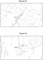
- Figures 2a-2e show examples of the different anomaly classes.
- the "on-road” class ( Figure 2a ) represents no anomalous behavior other than minor sensor or positioning errors (e.g. due to noise).
- the vehicle trajectory 209 follows the path of the road 210 but is slightly biased.
- the "off-road” class ( Figure 2b ) represents an off-map event.
- the driver has parked his/her vehicle 211 just off the road 210 (e.g. on a driveway, garage or unmapped car park).
- Other examples of off-road events include journeys through rural areas (e.g. over fields or a private road) or a significant short-cut outside the road network.
- the "illegal maneuver" class ( Figure 2c ) represents an impossible on-map trajectory when the sensor signal and map are likely fine.
- the driver has made a U-turn 212 that jumps from one road segment to its counterpart going in the opposite direction despite there being no valid connection therebetween.
- Other illegal maneuvers include driving the wrong way down a one-way street, turning the wrong way at a no-left-turn or no-right-turn junction, or ignoring a no-entry sign.
- the "sensor irregularity" class ( Figure 2d ) represents a problem with the sensor or a difficulty in obtaining the sensor data, such as sensor malfunctions, invalid sensor data (e.g. outside sensor range), non-Gaussian noise (e.g. strong bias of GNSS signal in one direction), non-stationary noise (e.g. GNSS behaves worse in built-up areas), and temporal or spatial gaps in the sensor data.
- a gap 213 is caused by an overpass blocking the GNSS signal resulting in a lack of data points at that location.
- Sensor gaps 213 appear as jumps where the reported location after a time gap is significantly further away, and can also be caused by signal interference, buildings, mountains, trees, tunnels or faulty sensors.
- the "unlikely geometry" class ( Figure 2e ) represents good positioning but a low likelihood as a result of minor mismatches in geometry and trajectory.
- the one-dimensional road representation 210 in the map data does not reflect the width of the physical road.
- the vehicle trajectory 209 exhibits a significant lateral offset.
- the model took account of as few features as possible in order to reduce computational demands at run-time.
- the features used were: log likelihood from the positioning system; U-turn (final difference of heading between start and end sensor points); length (distance, time, number of samples); off-road filter features (off-road score, off-road state); observations (velocity, course); state variables (velocity, course); state covariance matrices; and discrepancies between position estimate and observed positions (expressed as absolute distances).
- every data point is composed of several sensor points, every feature was aggregated using its mean, variance, minimum, maximum and first-to-last delta value.
- an L1-regularized logistic regression classifier and a random forest classifier.
- the former classifier fits a linear model with a sparsity-enforcing penalty resulting in fewer non-zero coefficients which makes the results easier to interpret.
- dataset standardization was also performed by taking the features, subtracting their means, and dividing them by their variance.
- the latter classifier constructs an ensemble of decision trees, making for an expressive non-linear model that can take into account feature combinations but is more difficult to interpret.
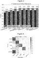
- the performance of each classifier was measured with an F1 score (a balanced metric of precision and recall), and a confusion matrix was generated to graphically illustrate which classes of anomaly the L1-regularized logistic regression classifier had difficulty distinguishing between.
- Figure 3 shows the F1 scores of the two different classifiers. As can be seen, the performance of the random forest classifier plateaued at 0.69 and the L1-regularized logistic regression classifier at 0.62, with nearly every feature set making a positive contribution.
- Figure 4 shows the confusion matrix for the L1-regularized logistic regression classifier. Whilst the model picked up on-road, off-road (parking) and sensor irregularity classes reasonably well, unlikely geometry errors were indistinguishable from normal on-road behavior. Also, illegal maneuvers were easily confused for parking events. The confusion occurred because the sensor fusion happened on the device itself. This suggests that pre-fused data is insufficient for detecting geometry errors but can still distinguish between other classes of anomaly. Reliable detection of off-road behavior therefore requires means to rule out other anomalies that can have similar signatures but different root causes. Some of these, especially those relating to sensor data itself, can be done in the scope of the positioning system by having them explicitly handled in its dynamics model, but that has the effect of increasing the degree of freedom of the system. Alternatively, a dataset with a higher positioning sensor accuracy (to more easily rule out sensor irregularities and on-road behavior), as well as multiple drivers on the same road network, may be used.
- the apparatus may be configured to obtain the additional data for the locations on the road network corresponding to the identified anomalies, and update the predefined map data using the obtained additional data to correct the errors therein.
- the apparatus may be configured to provide details of the identified anomalies to a further apparatus (e.g. server or central computer) which aggregates the anomalies for multiple vehicles by time, location and category and obtains the additional data for the locations on the road network corresponding to the aggregated anomalies.
- the additional data may be obtained from one or more of an embedded vehicle-based data collector, a crowd-sourced fleet of vehicles, a specially-equipped vehicle with suitable sensors (such as a global navigation satellite system (GNSS), an odometer, an inertial measurement unit, an inertial navigation system, an accelerometer, a gyroscope, a camera, a RADAR system and a LiDAR system), a downloadable map update, and satellite or aerial imagery.
- GNSS global navigation satellite system
- Figures 5 and 6 show the different respective parts of a distributed system for performing the method described herein.
- the apparatus 501 of Figure 5 (the first apparatus) may form at least part of a portable or in-vehicle satellite navigation device.
- the apparatus 501 comprises a sensor data collection module 514, a positioning system 515, an electronic display 516, an anomaly detection module 517, an anomaly classification module 518, and an anomaly reporting module 519.
- the sensor data collection module 514 collects data from one or more vehicle on-board sensors, and the positioning system 515 uses the sensor data to estimate the current vehicle position (and trajectory) on a map of the road network which is shown on a user interface of the electronic display 516.
- the anomaly detection module 517 is configured to compare the estimated position with the existing map data (and/or compare the estimated position based on sensor data from two or more different sensors) to detect any anomalies, and the anomaly classification module 518 is configured to classify the detected anomalies and provide the details of any anomalies which are likely caused by errors in the predefined map data to the anomaly reporting module 519 (e.g. via a cloud-based network).
- the electronic display 516 may also be configured to show the detected anomalies on the user interface in addition to the map of the road network.
- the apparatus 601 of Figure 6 may form at least part of a server or central computer.
- the apparatus 601 comprises an anomaly collection module 620, a data collection management module 621, a change detection module 623, and a map editing module 624.
- the anomaly collection module 620 is configured to receive the details of the detected anomalies from the anomaly reporting module 519 of the first apparatus 501, and aggregate the anomalies for multiple vehicles by time, location and category.
- the data collection management module 621 then receives details of the aggregated anomalies, and issues a data collection campaign order to one or more vehicles 622 instructing them to obtain additional data (e.g. more detailed data) for the locations on the road network corresponding to the aggregated anomalies.
- the change detection module 623 determines whether or not the existing map data needs to be updated (i.e. because there are discrepancies between the old and new map data), and then the map editing module 624 updates the map data if necessary.
- the anomaly detection 517 and anomaly classification 518 modules of the first apparatus 501 may form part of the second apparatus 601.
- the second apparatus 601 may be configured to receive the sensor data (or estimated position/trajectory) from the first apparatus 501 and perform the anomaly detection and classification itself.
- the one or more vehicles 622 tasked with obtaining the additional data may comprise the vehicles comprising the first apparatus 501.
- the sensor data collection module 514 may be configured to store the raw data received from the on-board sensors (e.g. in a buffer) and provide this data to the second apparatus 601 in response to the data collection campaign order.
- the first 501 or second 601 apparatus may be further configured to use the classification model to identify one or more anomalies which are likely caused by driver behavior (e.g. "off-road” or “illegal maneuver” classes illustrated in Figures 2b and 2c ), and provide user feedback based on the driver behavior.
- driver behavior e.g. "off-road” or "illegal maneuver” classes illustrated in Figures 2b and 2c
- the user feedback may comprise navigation guidance to assist the driver in navigating the unconventional route.
- the first 501 or second 601 apparatus may be further configured to use the classification model to identify one or more anomalies which are likely caused by at least one of sensor errors and positioning errors (e.g. "sensor irregularity" class illustrated in Figure 2d ), and provide user feedback based on the sensor or positioning errors.
- the user feedback may comprise a visual or audible warning to let the driver know not to rely on the navigation guidance for that part of the road network.
- Figure 7 shows the main steps 725-726 of a first method described herein.
- the method generally comprises: using a classification model to identify one or more anomalies between a monitored trajectory of a vehicle through a road network and predefined map data for the road network which are likely caused by errors in the predefined map data 725; and providing details of the one or more identified anomalies for use in obtaining additional data for the specific locations on the road network corresponding to the one or more identified anomalies in order to correct the errors in the predefined map data 726.
- Figure 8 shows the main steps 827-829 of a second method described herein.
- the method generally comprises: receiving details of one or more identified anomalies between a monitored trajectory of a vehicle through a road network and predefined map data for the road network which are likely caused by errors in the predefined map data 827; obtaining additional data for the specific locations on the road network corresponding to the one or more identified anomalies 828; and updating the predefined map data using the obtained additional data to correct the errors therein 829.
- Figure 9 shows a computer/processor readable medium 930 providing a computer program according to one embodiment.
- the computer program may comprise computer code configured to perform, control or enable one or more of the method steps 725-829 of Figure 7 or 8 .
- the computer/processor readable medium 930 is a disc such as a digital versatile disc (DVD) or a compact disc (CD).
- DVD digital versatile disc
- CD compact disc
- the computer/processor readable medium 930 may be any medium that has been programmed in such a way as to carry out an inventive function.
- the computer/processor readable medium 930 may be a fixed or removable memory device such as a hard drive, solid-state drive, memory stick (e.g. USB memory stick) or memory card (e.g.
- the computer code may be installed at the factory where the apparatus (e.g. portable or in-vehicle satellite navigation device), or vehicle comprising the apparatus, is being assembled. Later updates to the system may be made via the computer/processor readable medium 930 mentioned above.
- feature number 1 can also correspond to numbers 101, 201, 301 etc. These numbered features may appear in the figures but may not have been directly referred to within the description of these particular embodiments. These have still been provided in the figures to aid understanding of the further embodiments, particularly in relation to the features of similar earlier described embodiments.
- any mentioned apparatus/device and/or other features of particular mentioned apparatus/device may be provided by apparatus arranged such that they become configured to carry out the desired operations only when enabled, e.g. switched on, or the like. In such cases, they may not necessarily have the appropriate software loaded into the active memory in the non-enabled (e.g. switched off state) and only load the appropriate software in the enabled (e.g. on state).
- the apparatus may comprise hardware circuitry and/or firmware.
- the apparatus may comprise software loaded onto memory. Such software/computer programs may be recorded on the same memory/processor/functional units and/or on one or more memories/processors/functional units.
- a particular mentioned apparatus/device may be pre-programmed with the appropriate software to carry out desired operations, and wherein the appropriate software can be enabled for use by a user downloading a "key", for example, to unlock/enable the software and its associated functionality.
- Advantages associated with such embodiments can include a reduced requirement to download data when further functionality is required for a device, and this can be useful in examples where a device is perceived to have sufficient capacity to store such pre-programmed software for functionality that may not be enabled by a user.
- any mentioned apparatus/circuitry/elements/processor may have other functions in addition to the mentioned functions, and that these functions may be performed by the same apparatus/circuitry/elements/processor.
- One or more disclosed aspects may encompass the electronic distribution of associated computer programs and computer programs (which may be source/transport encoded) recorded on an appropriate carrier (e.g. memory, signal).
- any "computer” described herein can comprise a collection of one or more individual processors/processing elements that may or may not be located on the same circuit board, or the same region/position of a circuit board or even the same device. In some embodiments one or more of any mentioned processors may be distributed over a plurality of devices. The same or different processor/processing elements may perform one or more functions described herein.
- signal may refer to one or more signals transmitted as a series of transmitted and/or received signals.
- the series of signals may comprise one, two, three, four or even more individual signal components or distinct signals to make up said signalling. Some or all of these individual signals may be transmitted/received simultaneously, in sequence, and/or such that they temporally overlap one another.
- processors and memory may comprise a computer processor, Application Specific Integrated Circuit (ASIC), field-programmable gate array (FPGA), and/or other hardware components that have been programmed in such a way to carry out the inventive function.
- ASIC Application Specific Integrated Circuit
- FPGA field-programmable gate array
Landscapes
- Engineering & Computer Science (AREA)
- Remote Sensing (AREA)
- Radar, Positioning & Navigation (AREA)
- Physics & Mathematics (AREA)
- General Physics & Mathematics (AREA)
- Automation & Control Theory (AREA)
- Theoretical Computer Science (AREA)
- Mathematical Physics (AREA)
- Business, Economics & Management (AREA)
- Educational Administration (AREA)
- Educational Technology (AREA)
- Navigation (AREA)
- Traffic Control Systems (AREA)
Abstract
use a classification model to identify one or more anomalies between a monitored trajectory of a vehicle through a road network and predefined map data for the road network which are likely caused by errors in the predefined map data; and
provide details of the one or more identified anomalies for use in obtaining additional data for the specific locations on the road network corresponding to the one or more identified anomalies in order to correct the errors in the predefined map data.
Description
- The present disclosure relates to the field of route navigation, associated methods and apparatus, and in particular concerns an apparatus configured to classify anomalies between a monitored trajectory of a vehicle through a road network and predefined map data for the road network to identify one or more anomalies which are likely caused by errors in the predefined map data. Details of the one or more identified anomalies can then be used to obtain additional data for the specific locations on the road network corresponding to the one or more identified anomalies in order to correct the errors in the predefined map data.
- Certain disclosed example aspects/embodiments relate to portable or in-vehicle navigation devices. An in-vehicle navigation device may comprise hardware with similar characteristics to that of a mobile navigation device, but usually comprises less powerful hardware designed for the task. In the present case, the portable or in-vehicle navigation device should have access to a database containing map data (either online or offline) and sensor data from one or more sensors (e.g. GNSS, inertial measurement unit, accelerometer, compass, magnetometer, gyroscope, barometer/altitude sensor, camera, LiDAR, RADAR, ultrasound sensor and the like).
- Research is currently being done to develop improved navigation devices which can provide a user with more detailed and accurate information about road networks to further aid route navigation.
- One or more aspects/embodiments of the present disclosure may or may not address this issue.
- The listing or discussion of a prior-published document or any background in this specification should not necessarily be taken as an acknowledgement that the document or background is part of the state of the art or is common general knowledge.
- According to a first aspect, there is provided an apparatus comprising a processor and memory including computer program code, the memory and computer program code configured to, with the processor, enable the apparatus at least to:
- use a classification model to identify one or more anomalies between a monitored trajectory of a vehicle through a road network and predefined map data for the road network which are likely caused by errors in the predefined map data; and
- provide details of the one or more identified anomalies for use in obtaining additional data for the specific locations on the road network corresponding to the one or more identified anomalies in order to correct the errors in the predefined map data.
- The apparatus may be configured to compare the monitored trajectory and predefined map data to detect any anomalies therebetween.
- The apparatus may be configured to compare two or more monitored trajectories of the vehicle as determined simultaneously by different respective sensors on the vehicle to detect any anomalies therebetween.
- The classification model may be configured to classify the detected anomalies into one or more of the following classes: on-road, off-road, illegal manoeuvre, sensor irregularity, and unlikely geometry.
- The classification model may comprise a supervised machine learning algorithm.
- The classification model may comprise one or more of an L1-regularized logistic regression classifier and a random forest classifier.
- The anomalies may comprise discrepancies in one or more of position, speed and course between the monitored trajectory and predefined map data (e.g. which exceed a predefined margin of error).
- The apparatus may be configured to:
- obtain the additional data for the locations on the road network corresponding to the identified anomalies; and
- update the predefined map data using the obtained additional data to correct the errors therein.
- The apparatus may be configured to obtain the additional data from one or more of an embedded vehicle-based data collector, a crowd-sourced fleet of vehicles, a specially-equipped vehicle with suitable sensors, a downloadable map update, and satellite or aerial imagery.
- The apparatus may be configured to provide details of the identified anomalies to a further apparatus which aggregates the anomalies for multiple vehicles by time, location and category and obtains the additional data for the locations on the road network corresponding to the aggregated anomalies.
- The apparatus may be configured to:
- use the classification model to identify one or more anomalies which are likely caused by driver behaviour; and
- provide user feedback based on the driver behaviour.
- The user feedback may comprise navigation guidance.
- The apparatus may be configured to:
- use the classification model to identify one or more anomalies which are likely caused by at least one of sensor errors and positioning errors; and
- provide user feedback based on the sensor or positioning errors.
- The user feedback may comprise a visual or audible warning.
- The apparatus may be configured to display the monitored trajectory, road network and one or more anomalies on a user interface.
- The sensors may comprise at least one of a global navigation satellite system, an odometer, an inertial measurement unit, an inertial navigation system, an accelerometer, a gyroscope, a camera, a RADAR system and a LiDAR system.
- According to a further aspect, there is provided an apparatus comprising a processor and memory including computer program code, the memory and computer program code configured to, with the processor, enable the apparatus at least to:
- receive details of one or more identified anomalies between a monitored trajectory of a vehicle through a road network and predefined map data for the road network which are likely caused by errors in the predefined map data;
- obtain additional data for the specific locations on the road network corresponding to the one or more identified anomalies; and
- update the predefined map data using the obtained additional data to correct the errors therein.
- The apparatus may be one or more of an electronic device, a portable electronic device, a portable telecommunications device, a mobile phone, a personal digital assistant, a tablet, a phablet, a desktop computer, a laptop computer, a server, a smartphone, a smartwatch, smart eyewear, a portable satellite navigation device, an in-vehicle satellite navigation device, and a module for one or more of the same.
- According to a further aspect, there is provided a method comprising:
- using a classification model to identify one or more anomalies between a monitored trajectory of a vehicle through a road network and predefined map data for the road network which are likely caused by errors in the predefined map data; and
- providing details of the one or more identified anomalies for use in obtaining additional data for the specific locations on the road network corresponding to the one or more identified anomalies in order to correct the errors in the predefined map data.
- According to a further aspect, there is provided a method comprising:
- receiving details of one or more identified anomalies between a monitored trajectory of a vehicle through a road network and predefined map data for the road network which are likely caused by errors in the predefined map data;
- obtaining additional data for the specific locations on the road network corresponding to the one or more identified anomalies; and
- updating the predefined map data using the obtained additional data to correct the errors therein.
- According to a further aspect, there is provided a system comprising an apparatus configured to perform one of the methods described above and a further apparatus configured to perform the other method described above.
- The steps of any method disclosed herein do not have to be performed in the exact order disclosed, unless explicitly stated or understood by the skilled person.
- Corresponding computer programs (which may or may not be recorded on a carrier) for implementing one or more of the methods disclosed herein are also within the present disclosure and encompassed by one or more of the described example embodiments.
- The present disclosure includes one or more corresponding aspects, example embodiments or features in isolation or in various combinations whether or not specifically stated (including claimed) in that combination or in isolation. Corresponding means for performing one or more of the discussed functions are also within the present disclosure.
- The above summary is intended to be merely exemplary and non-limiting.
- A description is now given, by way of example only, with reference to the accompanying drawings, in which:-
-
Figure 1 shows an apparatus configured to perform one or more methods described herein; -
Figure 2a shows one example of an "on-road" anomaly; -
Figure 2b shows one example of an "off-road" anomaly; -
Figure 2c shows one example of an "illegal manoeuvre" anomaly; -
Figure 2d shows one example of a "sensor irregularity" anomaly; -
Figure 2e shows one example of an "unlikely geometry" anomaly; -
Figure 3 shows the measured performance of two different supervised machine learning algorithms during a classification test; -
Figure 4 shows a confusion matrix showing the results of the classification test for each class of anomaly; -
Figure 5 shows one half of a system configured to perform a method described herein; -
Figure 6 shows the other half of a system configured to perform a method described herein; -
Figure 7 shows the main steps of a method described herein; -
Figure 8 shows the main steps of another method described herein; and -
Figure 9 shows a computer-readable medium comprising a computer program configured to perform, control or enable one or more methods described herein. - Navigation devices need to be able to determine the current location of a vehicle relative to a map in order to provide route guidance to the driver of the vehicle. This is typically achieved using one or more on-board sensors, such as a global navigation satellite system (GNSS), an odometer, an inertial measurement unit, an inertial navigation system, an accelerometer, a gyroscope, a camera, a RADAR system and a LiDAR system. The state-of-the-art solution to this problem comprises multiple separate steps. First of all, dead reckoning (which typically combines a known reference position (e.g. from GNSS) with sensor data (e.g. from an inertial sensor)) is used to determine a trajectory and extrapolate this trajectory when no satellite signals are available (e.g. in tunnels). Next, map-matching is performed to associate the determined trajectory with the most likely path of travel on the road network. As there are often explicable shifts between the determined trajectory and the most likely path of travel (e.g. due to atmospheric conditions or reflections affecting the GNSS signals, or drifting of the dead reckoning), the map-matched position is then fed back to the dead reckoning unit so that it can be used to correct errors in the trajectory. Finally, if a lane assistance system is available, then this is used to keep track of which lane the vehicle is currently on. This module takes as an input the number of available lanes on the current road and tracks lane crossings, which allows the lateral position of the vehicle on the road to be tracked.
- To enable accurate route guidance, the map data to which the current location is compared must be up-to-date. Maintaining a high definition map requires not just an initial investment in obtaining the initial snapshot of the geometry, but also an ongoing effort in maintaining its correctness in light of constant changes and temporary disruptions. As semi-autonomous and autonomous vehicles continue to rely on the accuracy, the process of collecting the data to maintain the maps is an important consideration.
- The current process involves detecting changes in the road network by observing GNSS probe data emitted by cars equipped with navigation and positioning systems. While this technique is sufficient to determine direction of travel and the presence of a connection, the spatial accuracy and temporal sampling rate are insufficient as a high-definition geometry data source which could be used to re-construct a road geometry. Furthermore, GNSS probe data only contains the coordinates, speed and course, and lacks information on their estimated accuracy. In addition, the exact specifications of the system vary from vehicle to vehicle, so it is not known whether a particular system is using map feedback or any form of sensor fusion.
- Although additional on-board sensors (such as those listed above) may be used to supplement the GNSS probe data, this would increase data bandwidth for the car manufacturers who ultimately carry the cost of the mobile internet connections used to collect it.
- There will now be described an apparatus and associated methods that may address this issue.
-
Figure 1 shows anapparatus 101 configured to perform one or more methods described herein. Theapparatus 101 may be at least one of an electronic device, a portable electronic device, a portable telecommunications device, a mobile phone, a personal digital assistant, a tablet, a phablet, a desktop computer, a laptop computer, a server, a smartphone, a smartwatch, smart eyewear, a portable satellite navigation device, an in-vehicle satellite navigation device, and a module for one or more of the same. - In this example, the
apparatus 101 comprises aprocessor 102, amemory 103, atransceiver 104, apower supply 105, anelectronic display 106 and aloudspeaker 107, which are electrically connected to one another by adata bus 108. Theprocessor 102 is configured for general operation of theapparatus 101 by providing signalling to, and receiving signalling from, the other components to manage their operation. Thememory 103 is configured to store computer program code configured to perform, control or enable operation of theapparatus 101. Thememory 103 may also be configured to store settings for the other components. Theprocessor 102 may access thememory 103 to retrieve the component settings in order to manage the operation of the other components. Theprocessor 102 may be a microprocessor, including an Application Specific Integrated Circuit (ASIC). Thememory 103 may be a temporary storage medium such as a volatile random access memory. On the other hand, thememory 103 may be a permanent storage medium such as a hard disk drive, a flash memory, or a non-volatile random access memory. - The
transceiver 104 is configured to transmit data to, and/or receive data from, other apparatus/devices. As described in more detail below, this data may comprise the details of one or more anomalies identified between a monitored trajectory of a vehicle through a road network and predefined map data for the road network, and/or additional data for the specific locations on the road network corresponding to the one or more identified anomalies. - The
power supply 105 is configured to provide the other components with electrical power to enable their functionality, and may comprise one or more of a mains adapter, a battery, a capacitor, a supercapacitor, and a battery-capacitor hybrid. Theelectronic display 106 may be an LED, LCD or plasma display, and is configured to display visual content which is stored on (e.g. on the storage medium) or received by (e.g. via the transceiver) theapparatus 101. Similarly, theloudspeaker 107 is configured to output audio content which is stored on or received by theapparatus 101. The visual and audio content may comprise related components of a combined audio visual content. In some examples, the audio and/or visual content may comprise navigational content (such as geographical information and directions, distances, speeds or times of travel). - There may be a number of different reasons why a monitored vehicle trajectory deviates from the predefined map data. For example, there may be errors in the map topology or geometry, the driver may not obey the traffic rules or stay on the road, the on-board sensors may be inaccurate, or there may be disruptions to the sensor data collection process. It follows, therefore, that only some anomalies between the monitored vehicle trajectory and the predefined map data are actually caused by errors in the predefined map data which need to be corrected. It can, however, be difficult to distinguish those anomalies from others at the positioning level because many anomalies have confusingly similar signatures with equally low likelihoods of matching the predefined map data.
- The present apparatus is configured to use a classification model to identify one or more anomalies between a monitored trajectory of a vehicle through a road network and predefined map data for the road network which are likely caused by errors in the predefined map data; and provide details of the one or more identified anomalies for use in obtaining additional data for the specific locations on the road network corresponding to the one or more identified anomalies in order to correct the errors in the predefined map data.
- By limiting the additional data acquisition to those specific locations corresponding to the anomalies which are likely caused by errors in the map data, the amount of data required to update the map and the associated costs are reduced relative to existing systems.
- Before the present apparatus can identify anomalies relating to errors in the map data, the various anomalies between the monitored trajectory and the predefined map data need to be detected. The present apparatus may also be configured to perform this step. In this respect, the apparatus may be configured to compare the monitored trajectory and predefined map data to detect any anomalies therebetween prior to (or jointly with) use of the classification model. Additionally or alternatively, the apparatus may be configured to compare two or more monitored trajectories of the vehicle as determined simultaneously by different respective sensors on the vehicle to detect any anomalies therebetween prior to (or jointly with) use of the classification model. The anomalies themselves may comprise discrepancies in one or more of position, speed and course between the monitored trajectory and predefined map data.
- One specific example of anomaly detection will now be described. When detecting anomalies, every data point is defined as an event containing a timestamp and a list of sensor observations (e.g. position, speed, course). The data points are observed in sequences which are referred to herein as vehicle trajectories. The anomalousness probability of a sensor observation is obtained by performing a likelihood ratio test between the two hypotheses that the observation is explained by the road network or that the observation was emitted uniformly with a flat prior from free space:

- In order to determine the hypothesis that the observation is explained by the road network (i.e. the numerator of the likelihood ratio), the assumption that the vehicle is driving on the road network is utilised to derive a plurality of different paths of travel (or "road rails") representing the possibilities that the vehicle has to traverse the road network. A path of travel in this context consists of a drivable sequence of contiguous road segments in two or three dimensions reflecting the trajectory of the vehicle so far. The present apparatus may be configured to determine the plurality of different paths of travel by map-matching at least one known location of the vehicle with the predetermined map data. This involves finding a list of road segments near the known location and, for each road segment, creating a path of travel comprising that road segment. If the road segment can be travelled in both directions, two paths of travel may be created which extend in opposite directions from each end of the road segment.
- Once the plurality of different paths of travel have been determined, the apparatus is configured to compare data received from a sensor (or a plurality of sensors) on the vehicle with predetermined map data (e.g. a digital map, street level and aerial imagery, road coordinates, speed limits, road restrictions, etc) for each path of travel using respective recursive Bayesian filters. For example, the sensor may be a global navigation satellite system receiver, and the apparatus may be configured to compare geographical coordinates from the satellite data with the stored coordinates of a digital map. Similarly, the sensor may be a camera, and the apparatus may be configured to compare images recorded by the camera with stored street level images taken at various locations on the road network. The latter scenario may be particularly useful for detecting lanes or exits on a stretch of road.
- Each recursive Bayesian filter calculates a likelihood of the vehicle being currently located on the respective path of travel. The likelihood is therefore a measure of how well the respective path of travel fits the sensor data. In some cases, however, the likelihoods associated with each of the different paths of travel may indicate that none of these paths of travel sufficiently fit the sensor data (e.g. because the likelihoods are below a predefined threshold). In this scenario, the apparatus may be configured to determine one or more additional paths of travel. This may be achieved by map-matching (as described above), or by considering other paths of travel in proximity to the existing paths of travel. In some cases, none of the additional paths of travel may fit the sensor data either, which could indicate an error in the map data.
- The distribution of the test statistics Λ can be characterized by a χ 2 distribution with the degree of freedom as the difference of the numbers of free parameters in both likelihood models:

- The degree of freedom of the road model corresponds to the number of dimensions in the observation vector, and dofflat = 0. This enables an estimation of the probability that the current observation is anomalous given the state and observation values p(anomaly = 1|state, observation).
- It is also important to take account of the fact that it is unlikely that such a model will oscillate between an anomaly and normal state on a typical trajectory. The model should therefore remain on one of these states for several observation points. This is solved by returning a maximum likelihood decoding of a discrete time Markov chain that gives the most likely contiguous segments of anomalous and normal states on the trajectory. The contiguousness is ensured by representing the transition probability with an exponential distribution parametrized by rates λroad, λflat. The two-state system (i.e. anomalous and normal states) is defined with a pre-determined probability of anomaly, p0 , the observation probability as determined by the likelihood ratio model p( anomaly|state,observation), and the state transition matrix T(Δt):

- The terms in the transition matrix represent the probability of moving from one state to another as determined by the transition rates. For example, on longer time deltas, the probability of accepting one hypothesis versus another increases if the observation anomalousness probabilities are sufficient.
- Given these three parameters, a Viterbi decoding is then performed to determine which subsequences of the trajectory represent anomalous events. Although the nature of these anomalies is still unknown (and many of them could be false positives), they generate a dataset that can be further explored.
- Once the anomalies have been detected, the classification model is used to assign each of the different anomalies to a particular class. In this problem, the target variable for every data point is a discrete class or a superset of them. That is, for every data point xi, a model f is found that is able to produce predictions for the class of the anomaly taking account all preceding data points in the trajectory: ypred(i) = f(xi;xi_1,...x0). The examples described herein are constructed as event chains with up to 30 seconds of preceding events. There are several variations on how these event chains may be processed. Two different types of classification are described below: sequence-based classification and window-based classification. In both types, the classification is performed based on one or more features of the discrepancies between the monitored trajectory and the predefined map data. These features may comprise one or more of: discrepancies in position, velocity and heading; the cumulative change of heading within a time window; the likelihood of the sensor observation given the estimated state as given by the positioning system; the ratio of likelihoods between the one given by the map-matching positioning system and the one given by the flat prior model (described above); the ratio of likelihoods between the one given by the map-matching positioning system and the one given by a free-space positioning system; the likelihood as obtained from a partial sensor observation containing only the measurements of lateral position and heading when compared to the map geometry as given by the positioning system; the state covariance feature set having a covariance value for every combination of state dimensions; the innovation covariance feature set having a covariance value for every combination of observation dimensions; the anomaly class of the previous data point; and the time since the last initialization (age) of the candidate.
- In sequence-based models, the trajectories are considered to be chains of events where every individual event is annotated with a class (as opposed to the entire trajectory). The free parameters in this model that need to be trained are weights for individual event features and transition rates from one anomaly class to another. This approach was described above in relation to anomaly detection using a two-state discrete-time Hidden Markov Model in which the entire trajectory was decoded to obtain the most likely sequence of states. The advantage of a discrete-time sequence model is that the resulting sequences are relatively contiguous and free of fast oscillations between anomalies and non-anomalies.
- The sequence-based approach may be used for anomaly classification simultaneously with anomaly detection by considering the possibility of several different states (i.e. various distinct classes) rather than a binary two-state system (i.e. anomaly vs no anomaly). In this scenario, however, the model has more free parameters: a transition rate matrix between all pairs of states, and a feature weight matrix describing the influence of every observed feature for every possible every state where the goal is to infer the most likely (or most optimal) sequence.
- Sequence-based classification allows the use of several classes of sequence modeling, such as Hidden Markov Models (as described above), Conditional Random Fields or Recurrent Neural Networks.
- Window-based classification, on the other hand, is a method to convert a sequence classification problem to a typical example classification problem by means of reducing the entire sequence into a single feature vector. For example, given that every example sequence can be described with feature i at step j as xij , a windowed reduction of the features as xreduced,i = reductionj,j-k(xij) can be obtained, where the reduction happens over a window size of k, using one or more of the following operations: mean, median, variance, minimum, maximum and delta (difference from first to last value). All meaningful reductions of the features across the sequence can then be generated, and any standard supervised classification approach can be used to implement it. The window-based classification technique also exhibits the property of temporal consistency, meaning that it does not switch erratically between different states. It can therefore also be used as a joint anomaly detection and classification model.
- In order to demonstrate the classification of identified anomalies, data from 21 drivers was obtained from a global data collection campaign in which 828 features were detected as anomalous at the initial anomaly detection step. The vehicles were equipped with positioning devices that recorded their position, velocity and course. In this experiment, the classification model was configured to classify the detected anomalies into the following classes: "on-road", "off-road", "illegal maneuver", "sensor irregularity" and "unlikely geometry".
-
Figures 2a-2e show examples of the different anomaly classes. The "on-road" class (Figure 2a ) represents no anomalous behavior other than minor sensor or positioning errors (e.g. due to noise). In this example, thevehicle trajectory 209 follows the path of theroad 210 but is slightly biased. - The "off-road" class (
Figure 2b ) represents an off-map event. In this example, the driver has parked his/hervehicle 211 just off the road 210 (e.g. on a driveway, garage or unmapped car park). Other examples of off-road events include journeys through rural areas (e.g. over fields or a private road) or a significant short-cut outside the road network. - The "illegal maneuver" class (
Figure 2c ) represents an impossible on-map trajectory when the sensor signal and map are likely fine. In this example, the driver has made aU-turn 212 that jumps from one road segment to its counterpart going in the opposite direction despite there being no valid connection therebetween. Other illegal maneuvers include driving the wrong way down a one-way street, turning the wrong way at a no-left-turn or no-right-turn junction, or ignoring a no-entry sign. - The "sensor irregularity" class (
Figure 2d ) represents a problem with the sensor or a difficulty in obtaining the sensor data, such as sensor malfunctions, invalid sensor data (e.g. outside sensor range), non-Gaussian noise (e.g. strong bias of GNSS signal in one direction), non-stationary noise (e.g. GNSS behaves worse in built-up areas), and temporal or spatial gaps in the sensor data. In this example, agap 213 is caused by an overpass blocking the GNSS signal resulting in a lack of data points at that location.Sensor gaps 213 appear as jumps where the reported location after a time gap is significantly further away, and can also be caused by signal interference, buildings, mountains, trees, tunnels or faulty sensors. - The "unlikely geometry" class (
Figure 2e ) represents good positioning but a low likelihood as a result of minor mismatches in geometry and trajectory. In this example, the one-dimensional road representation 210 in the map data does not reflect the width of the physical road. As a result, thevehicle trajectory 209 exhibits a significant lateral offset. - The actual (i.e. real) counts of data points of every detected anomaly class were as follows: "On-road": 440; "Off-road": 250; "Illegal maneuver": 29; "Sensor irregularity": 93; and "Wrong geometry": 9.
- In order to pose this as a classification test, a feature representation had to be defined. In this particular experiment, it was preferable that the model took account of as few features as possible in order to reduce computational demands at run-time. In this respect, the features used were: log likelihood from the positioning system; U-turn (final difference of heading between start and end sensor points); length (distance, time, number of samples); off-road filter features (off-road score, off-road state); observations (velocity, course); state variables (velocity, course); state covariance matrices; and discrepancies between position estimate and observed positions (expressed as absolute distances). Furthermore, since every data point is composed of several sensor points, every feature was aggregated using its mean, variance, minimum, maximum and first-to-last delta value.
- In this experiment, two different classifiers comprising supervised machine learning algorithms were tested: an L1-regularized logistic regression classifier and a random forest classifier. The former classifier fits a linear model with a sparsity-enforcing penalty resulting in fewer non-zero coefficients which makes the results easier to interpret. In this case, dataset standardization was also performed by taking the features, subtracting their means, and dividing them by their variance. The latter classifier constructs an ensemble of decision trees, making for an expressive non-linear model that can take into account feature combinations but is more difficult to interpret. The performance of each classifier was measured with an F1 score (a balanced metric of precision and recall), and a confusion matrix was generated to graphically illustrate which classes of anomaly the L1-regularized logistic regression classifier had difficulty distinguishing between.
-
Figure 3 shows the F1 scores of the two different classifiers. As can be seen, the performance of the random forest classifier plateaued at 0.69 and the L1-regularized logistic regression classifier at 0.62, with nearly every feature set making a positive contribution. -
Figure 4 shows the confusion matrix for the L1-regularized logistic regression classifier. Whilst the model picked up on on-road, off-road (parking) and sensor irregularity classes reasonably well, unlikely geometry errors were indistinguishable from normal on-road behavior. Also, illegal maneuvers were easily confused for parking events. The confusion occurred because the sensor fusion happened on the device itself. This suggests that pre-fused data is insufficient for detecting geometry errors but can still distinguish between other classes of anomaly. Reliable detection of off-road behavior therefore requires means to rule out other anomalies that can have similar signatures but different root causes. Some of these, especially those relating to sensor data itself, can be done in the scope of the positioning system by having them explicitly handled in its dynamics model, but that has the effect of increasing the degree of freedom of the system. Alternatively, a dataset with a higher positioning sensor accuracy (to more easily rule out sensor irregularities and on-road behavior), as well as multiple drivers on the same road network, may be used. - Once the detected anomalies between the vehicle trajectory and the predefined map data have been detected and classified, the apparatus may be configured to obtain the additional data for the locations on the road network corresponding to the identified anomalies, and update the predefined map data using the obtained additional data to correct the errors therein. In other examples, however, the apparatus may be configured to provide details of the identified anomalies to a further apparatus (e.g. server or central computer) which aggregates the anomalies for multiple vehicles by time, location and category and obtains the additional data for the locations on the road network corresponding to the aggregated anomalies.
- In both scenarios, the additional data may be obtained from one or more of an embedded vehicle-based data collector, a crowd-sourced fleet of vehicles, a specially-equipped vehicle with suitable sensors (such as a global navigation satellite system (GNSS), an odometer, an inertial measurement unit, an inertial navigation system, an accelerometer, a gyroscope, a camera, a RADAR system and a LiDAR system), a downloadable map update, and satellite or aerial imagery. When using a crowd-sourced fleet of vehicles, data collection instructions may be embedded in the specific locations on the map that need updating.
-
Figures 5 and 6 show the different respective parts of a distributed system for performing the method described herein. Theapparatus 501 ofFigure 5 (the first apparatus) may form at least part of a portable or in-vehicle satellite navigation device. Theapparatus 501 comprises a sensordata collection module 514, apositioning system 515, anelectronic display 516, ananomaly detection module 517, ananomaly classification module 518, and ananomaly reporting module 519. - The sensor
data collection module 514 collects data from one or more vehicle on-board sensors, and thepositioning system 515 uses the sensor data to estimate the current vehicle position (and trajectory) on a map of the road network which is shown on a user interface of theelectronic display 516. Theanomaly detection module 517 is configured to compare the estimated position with the existing map data (and/or compare the estimated position based on sensor data from two or more different sensors) to detect any anomalies, and theanomaly classification module 518 is configured to classify the detected anomalies and provide the details of any anomalies which are likely caused by errors in the predefined map data to the anomaly reporting module 519 (e.g. via a cloud-based network). Theelectronic display 516 may also be configured to show the detected anomalies on the user interface in addition to the map of the road network. - The
apparatus 601 ofFigure 6 (the second apparatus) may form at least part of a server or central computer. Theapparatus 601 comprises ananomaly collection module 620, a datacollection management module 621, achange detection module 623, and amap editing module 624. Theanomaly collection module 620 is configured to receive the details of the detected anomalies from theanomaly reporting module 519 of thefirst apparatus 501, and aggregate the anomalies for multiple vehicles by time, location and category. The datacollection management module 621 then receives details of the aggregated anomalies, and issues a data collection campaign order to one ormore vehicles 622 instructing them to obtain additional data (e.g. more detailed data) for the locations on the road network corresponding to the aggregated anomalies. Once the additional data has been obtained from the one ormore vehicles 622, thechange detection module 623 determines whether or not the existing map data needs to be updated (i.e. because there are discrepancies between the old and new map data), and then themap editing module 624 updates the map data if necessary. - In some cases, the
anomaly detection 517 andanomaly classification 518 modules of thefirst apparatus 501 may form part of thesecond apparatus 601. In this scenario, thesecond apparatus 601 may be configured to receive the sensor data (or estimated position/trajectory) from thefirst apparatus 501 and perform the anomaly detection and classification itself. - Furthermore, the one or
more vehicles 622 tasked with obtaining the additional data may comprise the vehicles comprising thefirst apparatus 501. In this situation, the sensordata collection module 514 may be configured to store the raw data received from the on-board sensors (e.g. in a buffer) and provide this data to thesecond apparatus 601 in response to the data collection campaign order. - The first 501 or second 601 apparatus may be further configured to use the classification model to identify one or more anomalies which are likely caused by driver behavior (e.g. "off-road" or "illegal maneuver" classes illustrated in
Figures 2b and 2c ), and provide user feedback based on the driver behavior. The user feedback may comprise navigation guidance to assist the driver in navigating the unconventional route. - Similarly, the first 501 or second 601 apparatus may be further configured to use the classification model to identify one or more anomalies which are likely caused by at least one of sensor errors and positioning errors (e.g. "sensor irregularity" class illustrated in
Figure 2d ), and provide user feedback based on the sensor or positioning errors. The user feedback may comprise a visual or audible warning to let the driver know not to rely on the navigation guidance for that part of the road network. -
Figure 7 shows the main steps 725-726 of a first method described herein. The method generally comprises: using a classification model to identify one or more anomalies between a monitored trajectory of a vehicle through a road network and predefined map data for the road network which are likely caused by errors in thepredefined map data 725; and providing details of the one or more identified anomalies for use in obtaining additional data for the specific locations on the road network corresponding to the one or more identified anomalies in order to correct the errors in thepredefined map data 726. -
Figure 8 shows the main steps 827-829 of a second method described herein. The method generally comprises: receiving details of one or more identified anomalies between a monitored trajectory of a vehicle through a road network and predefined map data for the road network which are likely caused by errors in thepredefined map data 827; obtaining additional data for the specific locations on the road network corresponding to the one or more identifiedanomalies 828; and updating the predefined map data using the obtained additional data to correct the errors therein 829. -
Figure 9 shows a computer/processorreadable medium 930 providing a computer program according to one embodiment. The computer program may comprise computer code configured to perform, control or enable one or more of the method steps 725-829 ofFigure 7 or 8 . In this example, the computer/processorreadable medium 930 is a disc such as a digital versatile disc (DVD) or a compact disc (CD). In other embodiments, the computer/processorreadable medium 930 may be any medium that has been programmed in such a way as to carry out an inventive function. The computer/processorreadable medium 930 may be a fixed or removable memory device such as a hard drive, solid-state drive, memory stick (e.g. USB memory stick) or memory card (e.g. compact flash, SD, mini SD, micro SD or nano SD). The computer code may be installed at the factory where the apparatus (e.g. portable or in-vehicle satellite navigation device), or vehicle comprising the apparatus, is being assembled. Later updates to the system may be made via the computer/processorreadable medium 930 mentioned above. - Other embodiments depicted in the figures have been provided with reference numerals that correspond to similar features of earlier described embodiments. For example, feature number 1 can also correspond to
numbers 101, 201, 301 etc. These numbered features may appear in the figures but may not have been directly referred to within the description of these particular embodiments. These have still been provided in the figures to aid understanding of the further embodiments, particularly in relation to the features of similar earlier described embodiments. - It will be appreciated to the skilled reader that any mentioned apparatus/device and/or other features of particular mentioned apparatus/device may be provided by apparatus arranged such that they become configured to carry out the desired operations only when enabled, e.g. switched on, or the like. In such cases, they may not necessarily have the appropriate software loaded into the active memory in the non-enabled (e.g. switched off state) and only load the appropriate software in the enabled (e.g. on state).
- The apparatus may comprise hardware circuitry and/or firmware. The apparatus may comprise software loaded onto memory. Such software/computer programs may be recorded on the same memory/processor/functional units and/or on one or more memories/processors/functional units.
- In some embodiments, a particular mentioned apparatus/device may be pre-programmed with the appropriate software to carry out desired operations, and wherein the appropriate software can be enabled for use by a user downloading a "key", for example, to unlock/enable the software and its associated functionality. Advantages associated with such embodiments can include a reduced requirement to download data when further functionality is required for a device, and this can be useful in examples where a device is perceived to have sufficient capacity to store such pre-programmed software for functionality that may not be enabled by a user.
- It will be appreciated that any mentioned apparatus/circuitry/elements/processor may have other functions in addition to the mentioned functions, and that these functions may be performed by the same apparatus/circuitry/elements/processor. One or more disclosed aspects may encompass the electronic distribution of associated computer programs and computer programs (which may be source/transport encoded) recorded on an appropriate carrier (e.g. memory, signal).
- It will be appreciated that any "computer" described herein can comprise a collection of one or more individual processors/processing elements that may or may not be located on the same circuit board, or the same region/position of a circuit board or even the same device. In some embodiments one or more of any mentioned processors may be distributed over a plurality of devices. The same or different processor/processing elements may perform one or more functions described herein.
- It will be appreciated that the term "signalling" may refer to one or more signals transmitted as a series of transmitted and/or received signals. The series of signals may comprise one, two, three, four or even more individual signal components or distinct signals to make up said signalling. Some or all of these individual signals may be transmitted/received simultaneously, in sequence, and/or such that they temporally overlap one another.
- With reference to any discussion of any mentioned computer and/or processor and memory (e.g. including ROM, CD-ROM etc), these may comprise a computer processor, Application Specific Integrated Circuit (ASIC), field-programmable gate array (FPGA), and/or other hardware components that have been programmed in such a way to carry out the inventive function.
- The applicant hereby discloses in isolation each individual feature described herein and any combination of two or more such features, to the extent that such features or combinations are capable of being carried out based on the present specification as a whole, in the light of the common general knowledge of a person skilled in the art, irrespective of whether such features or combinations of features solve any problems disclosed herein, and without limitation to the scope of the claims. The applicant indicates that the disclosed aspects/embodiments may consist of any such individual feature or combination of features. In view of the foregoing description it will be evident to a person skilled in the art that various modifications may be made within the scope of the disclosure.
- While there have been shown and described and pointed out fundamental novel features as applied to different embodiments thereof, it will be understood that various omissions and substitutions and changes in the form and details of the devices and methods described may be made by those skilled in the art without departing from the spirit of the invention. For example, it is expressly intended that all combinations of those elements and/or method steps which perform substantially the same function in substantially the same way to achieve the same results are within the scope of the invention. Moreover, it should be recognized that structures and/or elements and/or method steps shown and/or described in connection with any disclosed form or embodiment may be incorporated in any other disclosed or described or suggested form or embodiment as a general matter of design choice. Furthermore, in the claims means-plus-function clauses are intended to cover the structures described herein as performing the recited function and not only structural equivalents, but also equivalent structures. Thus although a nail and a screw may not be structural equivalents in that a nail employs a cylindrical surface to secure wooden parts together, whereas a screw employs a helical surface, in the environment of fastening wooden parts, a nail and a screw may be equivalent structures.
Claims (15)
- An apparatus comprising a processor and memory including computer program code, the memory and computer program code configured to, with the processor, enable the apparatus at least to:use a classification model to identify one or more anomalies between a monitored trajectory of a vehicle through a road network and predefined map data for the road network which are likely caused by errors in the predefined map data; andprovide details of the one or more identified anomalies for use in obtaining additional data for the specific locations on the road network corresponding to the one or more identified anomalies in order to correct the errors in the predefined map data.
- The apparatus of claim 1, wherein the apparatus is configured to compare the monitored trajectory and predefined map data to detect any anomalies therebetween.
- The apparatus of claim 1 or 2, wherein the apparatus is configured to compare two or more monitored trajectories of the vehicle as determined simultaneously by different respective sensors on the vehicle to detect any anomalies therebetween.
- The apparatus of claim 2 or 3, wherein the classification model is configured to classify the detected anomalies into one or more of the following classes: on-road, off-road, illegal manoeuvre, sensor irregularity, and unlikely geometry.
- The apparatus of any preceding claim, wherein the classification model comprises a supervised machine learning algorithm.
- The apparatus of any preceding claim, wherein the anomalies comprise discrepancies in one or more of position, speed and course between the monitored trajectory and predefined map data.
- The apparatus of any preceding claim, wherein the apparatus is configured to:obtain the additional data for the locations on the road network corresponding to the identified anomalies; andupdate the predefined map data using the obtained additional data to correct the errors therein.
- The apparatus of any preceding claim, wherein the apparatus is configured to provide details of the identified anomalies to a further apparatus which aggregates the anomalies for multiple vehicles by time, location and category and obtains the additional data for the locations on the road network corresponding to the aggregated anomalies.
- The apparatus of any preceding claim, wherein the apparatus is configured to:use the classification model to identify one or more anomalies which are likely caused by driver behaviour; andprovide user feedback based on the driver behaviour.
- The apparatus of any preceding claim, wherein the apparatus is configured to:use the classification model to identify one or more anomalies which are likely caused by at least one of sensor errors and positioning errors; andprovide user feedback based on the sensor or positioning errors.
- The apparatus of any preceding claim, wherein the apparatus is configured to display the monitored trajectory, road network and one or more anomalies on a user interface.
- The apparatus of claim 3 and any claim dependent thereon, wherein the sensors comprise at least one of a global navigation satellite system, an odometer, an inertial measurement unit, an inertial navigation system, an accelerometer, a gyroscope, a camera, a RADAR system and a LiDAR system.
- An apparatus comprising a processor and memory including computer program code, the memory and computer program code configured to, with the processor, enable the apparatus at least to:receive details of one or more identified anomalies between a monitored trajectory of a vehicle through a road network and predefined map data for the road network which are likely caused by errors in the predefined map data;obtain additional data for the specific locations on the road network corresponding to the one or more identified anomalies; andupdate the predefined map data using the obtained additional data to correct the errors therein.
- A method comprising:using a classification model to identify one or more anomalies between a monitored trajectory of a vehicle through a road network and predefined map data for the road network which are likely caused by errors in the predefined map data; andproviding details of the one or more identified anomalies for use in obtaining additional data for the specific locations on the road network corresponding to the one or more identified anomalies in order to correct the errors in the predefined map data.
- A method comprising:receiving details of one or more identified anomalies between a monitored trajectory of a vehicle through a road network and predefined map data for the road network which are likely caused by errors in the predefined map data;obtaining additional data for the specific locations on the road network corresponding to the one or more identified anomalies; andupdating the predefined map data using the obtained additional data to correct the errors therein.
Priority Applications (2)
| Application Number | Priority Date | Filing Date | Title |
|---|---|---|---|
| EP17154967.8A EP3358303B1 (en) | 2017-02-07 | 2017-02-07 | An apparatus and associated methods for use in updating map data |
| US15/889,309 US10996061B2 (en) | 2017-02-07 | 2018-02-06 | Apparatus and associated method for use in updating map data |
Applications Claiming Priority (1)
| Application Number | Priority Date | Filing Date | Title |
|---|---|---|---|
| EP17154967.8A EP3358303B1 (en) | 2017-02-07 | 2017-02-07 | An apparatus and associated methods for use in updating map data |
Publications (2)
| Publication Number | Publication Date |
|---|---|
| EP3358303A1 true EP3358303A1 (en) | 2018-08-08 |
| EP3358303B1 EP3358303B1 (en) | 2021-09-01 |
Family
ID=57984851
Family Applications (1)
| Application Number | Title | Priority Date | Filing Date |
|---|---|---|---|
| EP17154967.8A Active EP3358303B1 (en) | 2017-02-07 | 2017-02-07 | An apparatus and associated methods for use in updating map data |
Country Status (2)
| Country | Link |
|---|---|
| US (1) | US10996061B2 (en) |
| EP (1) | EP3358303B1 (en) |
Cited By (8)
| Publication number | Priority date | Publication date | Assignee | Title |
|---|---|---|---|---|
| CN109961106A (en) * | 2019-04-18 | 2019-07-02 | 北京百度网讯科技有限公司 | Training method and device for trajectory classification model, and electronic device |
| EP3696511A1 (en) * | 2019-02-14 | 2020-08-19 | HERE Global B.V. | Method, apparatus, and system for providing a campaign management platform to update map data |
| CN111624624A (en) * | 2020-04-21 | 2020-09-04 | 腾讯科技(深圳)有限公司 | Method and device for processing differential data |
| CN112699203A (en) * | 2021-01-14 | 2021-04-23 | 腾讯科技(深圳)有限公司 | Road network data processing method and device |
| CN112732446A (en) * | 2021-01-15 | 2021-04-30 | 腾讯科技(深圳)有限公司 | Task processing method and device and storage medium |
| CN113312363A (en) * | 2020-11-12 | 2021-08-27 | 中南大学 | Automatic method for updating overpass increment and maintaining topological connectivity of overpass increment |
| CN113449062A (en) * | 2021-06-30 | 2021-09-28 | 北京百度网讯科技有限公司 | Track processing method and device, electronic equipment and storage medium |
| US20230140079A1 (en) * | 2021-11-04 | 2023-05-04 | Hitachi Astemo, Ltd. | Method and Systems for Detection Accuracy Ranking and Vehicle Instructions |
Families Citing this family (19)
| Publication number | Priority date | Publication date | Assignee | Title |
|---|---|---|---|---|
| EP3339807B1 (en) * | 2016-12-20 | 2024-03-13 | HERE Global B.V. | An apparatus and associated methods for determining the location of a vehicle |
| US10587635B2 (en) * | 2017-03-31 | 2020-03-10 | The Boeing Company | On-board networked anomaly detection (ONAD) modules |
| US20190056231A1 (en) * | 2017-08-15 | 2019-02-21 | GM Global Technology Operations LLC | Method and apparatus for participative map anomaly detection and correction |
| JP6541924B1 (en) * | 2017-11-22 | 2019-07-10 | 三菱電機株式会社 | Map collection system, map server device, in-vehicle device, and map collection method |
| US11416622B2 (en) | 2018-08-20 | 2022-08-16 | Veracode, Inc. | Open source vulnerability prediction with machine learning ensemble |
| CN111324680B (en) * | 2019-01-25 | 2021-05-18 | 北京嘀嘀无限科技发展有限公司 | Information display method and device |
| US11126200B2 (en) * | 2019-02-14 | 2021-09-21 | Here Global B.V. | Method, apparatus, and system for providing an interface for publishing sensor data requests in campaign management platform |
| JP6921343B2 (en) * | 2019-03-18 | 2021-08-18 | 三菱電機株式会社 | Map information correction device, mobile body, map information correction system, map information correction method, map information correction program, control circuit and storage medium |
| GB201907342D0 (en) * | 2019-05-24 | 2019-07-10 | Tomtom Global Content Bv | Supplementing electronic map data from user behaviour |
| US11549815B2 (en) * | 2019-06-28 | 2023-01-10 | GM Cruise Holdings LLC. | Map change detection |
| US20220172134A1 (en) * | 2020-12-02 | 2022-06-02 | Quantum Spatial Inc. | Methods and apparatus for automatic risk assessment of power outages |
| US20220404167A1 (en) * | 2021-06-22 | 2022-12-22 | GM Global Technology Operations LLC | Roadway occlusion detection and reasoning |
| CN113515536B (en) * | 2021-07-13 | 2022-12-13 | 北京百度网讯科技有限公司 | Map updating method, device, equipment, server and storage medium |
| CN115752459A (en) * | 2021-09-02 | 2023-03-07 | 中国人民解放军战略支援部队信息工程大学 | Trajectory rectification method based on indoor position network model |
| CN113970330B (en) * | 2021-12-22 | 2022-04-19 | 比亚迪股份有限公司 | Vehicle multi-sensor fusion positioning method, computer equipment and storage medium |
| US12576874B2 (en) * | 2021-12-23 | 2026-03-17 | Intel Corporation | Driver scoring system and method using optimum path deviation |
| CN114419883B (en) * | 2022-01-07 | 2023-06-16 | 北京百度网讯科技有限公司 | Method and device for identifying intersection missing traffic restriction information and electronic equipment |
| CN114771599B (en) * | 2022-04-27 | 2024-01-05 | 上海申浙数智轨道科技有限公司 | Track fault positioning method, system, storage medium and electronic equipment |
| US12359934B1 (en) * | 2022-04-29 | 2025-07-15 | Zoox, Inc. | Validation of a road network map based on location bounded rules |
Citations (4)
| Publication number | Priority date | Publication date | Assignee | Title |
|---|---|---|---|---|
| US20050283699A1 (en) * | 2004-06-21 | 2005-12-22 | Kimihiro Nomura | Map error information obtaining system and map error information obtaining method |
| WO2009059766A1 (en) * | 2007-11-06 | 2009-05-14 | Tele Atlas North America Inc. | Method and system for the use of probe data from multiple vehicles to detect real world changes for use in updating a map |
| US20140074847A1 (en) * | 2012-06-29 | 2014-03-13 | Tomtom Belgium N.V. | Method and apparatus for detecting deviations from map data |
| WO2014125802A1 (en) * | 2013-02-12 | 2014-08-21 | Zenrin Co., Ltd. | New road detection logic |
Family Cites Families (24)
| Publication number | Priority date | Publication date | Assignee | Title |
|---|---|---|---|---|
| US5436840A (en) | 1993-03-05 | 1995-07-25 | Motorola, Inc. | Vehicle position uncertainty area correction method and apparatus therefor |
| US6385539B1 (en) | 1999-08-13 | 2002-05-07 | Daimlerchrysler Ag | Method and system for autonomously developing or augmenting geographical databases by mining uncoordinated probe data |
| US6681180B2 (en) | 2001-01-29 | 2004-01-20 | The Board Of Trustees Of The Leland Stanford Junior University | Determination and control of vehicle sideslip using GPS |
| US7706971B2 (en) | 2005-07-21 | 2010-04-27 | The Boeing Company | System and method for data mapping and map discrepancy reporting |
| US7724184B2 (en) | 2006-02-21 | 2010-05-25 | Honeywell International Inc. | System and method for detecting false navigation signals |
| CN101517360B (en) * | 2006-09-21 | 2012-02-22 | 三菱电机株式会社 | Map information processing device |
| JP4597241B2 (en) * | 2006-10-12 | 2010-12-15 | 三菱電機株式会社 | Map information processing device |
| US8073617B2 (en) * | 2006-12-27 | 2011-12-06 | Aisin Aw Co., Ltd. | Map information generating systems, methods, and programs |
| US8060275B2 (en) | 2007-01-19 | 2011-11-15 | Ford Global Technologies, Llc | Rough road detection system used in an on-board diagnostic system |
| US8284995B2 (en) | 2008-07-16 | 2012-10-09 | Volkswagen Of America, Inc. | Method for updating a geographic database for an in-vehicle navigation system |
| US8762046B2 (en) | 2008-10-01 | 2014-06-24 | Navteq B.V. | Creating geometry for advanced driver assistance systems |
| US8560218B1 (en) | 2008-12-31 | 2013-10-15 | Dp Technologies, Inc. | Method and apparatus to correct for erroneous global positioning system data |
| EP2409288A1 (en) * | 2009-03-16 | 2012-01-25 | Tom Tom Polska SP. Z.O.O. | Method for updating digital maps using altitude information |
| US8786845B2 (en) | 2010-04-08 | 2014-07-22 | Navteq B.V. | System and method of generating and using open sky data |
| US9696166B2 (en) | 2010-10-06 | 2017-07-04 | Google Inc. | Automated identification of anomalous map data |
| US8718927B2 (en) | 2012-03-12 | 2014-05-06 | Strava, Inc. | GPS data repair |
| US9423261B2 (en) * | 2013-02-19 | 2016-08-23 | Here Global B.V. | Path curve confidence factors |
| US9288630B2 (en) | 2013-10-28 | 2016-03-15 | Verizon Patent And Licensing Inc. | Method and apparatus for providing positioning services using multi-spacing clustering |
| US9668086B2 (en) * | 2013-11-29 | 2017-05-30 | At&T Intellectual Property I, L.P. | Methods, devices, and computer readable storage devices for providing optimized location information |
| JP6427908B2 (en) * | 2014-03-24 | 2018-11-28 | アイシン・エィ・ダブリュ株式会社 | Map information generation system, method and program |
| US9361797B1 (en) | 2014-12-11 | 2016-06-07 | Here Global B.V. | Detecting road condition changes from probe data |
| US9884622B2 (en) * | 2015-12-29 | 2018-02-06 | Thunder Power New Energy Vehicle Development Company Limited | Vehicle condition detection and warning system |
| US10502577B2 (en) | 2016-06-30 | 2019-12-10 | Here Global B.V. | Iterative map learning based on vehicle on-board sensor data |
| US10072937B2 (en) | 2016-07-14 | 2018-09-11 | Here Global B.V. | Map having computer executable instructions embedded therein |
-
2017
- 2017-02-07 EP EP17154967.8A patent/EP3358303B1/en active Active
-
2018
- 2018-02-06 US US15/889,309 patent/US10996061B2/en active Active
Patent Citations (4)
| Publication number | Priority date | Publication date | Assignee | Title |
|---|---|---|---|---|
| US20050283699A1 (en) * | 2004-06-21 | 2005-12-22 | Kimihiro Nomura | Map error information obtaining system and map error information obtaining method |
| WO2009059766A1 (en) * | 2007-11-06 | 2009-05-14 | Tele Atlas North America Inc. | Method and system for the use of probe data from multiple vehicles to detect real world changes for use in updating a map |
| US20140074847A1 (en) * | 2012-06-29 | 2014-03-13 | Tomtom Belgium N.V. | Method and apparatus for detecting deviations from map data |
| WO2014125802A1 (en) * | 2013-02-12 | 2014-08-21 | Zenrin Co., Ltd. | New road detection logic |
Cited By (12)
| Publication number | Priority date | Publication date | Assignee | Title |
|---|---|---|---|---|
| EP3696511A1 (en) * | 2019-02-14 | 2020-08-19 | HERE Global B.V. | Method, apparatus, and system for providing a campaign management platform to update map data |
| US11280620B2 (en) | 2019-02-14 | 2022-03-22 | Here Global B.V. | Method, apparatus, and system for providing a campaign management platform to update map data |
| CN109961106A (en) * | 2019-04-18 | 2019-07-02 | 北京百度网讯科技有限公司 | Training method and device for trajectory classification model, and electronic device |
| CN111624624A (en) * | 2020-04-21 | 2020-09-04 | 腾讯科技(深圳)有限公司 | Method and device for processing differential data |
| CN113312363A (en) * | 2020-11-12 | 2021-08-27 | 中南大学 | Automatic method for updating overpass increment and maintaining topological connectivity of overpass increment |
| CN112699203A (en) * | 2021-01-14 | 2021-04-23 | 腾讯科技(深圳)有限公司 | Road network data processing method and device |
| CN112699203B (en) * | 2021-01-14 | 2022-02-08 | 腾讯科技(深圳)有限公司 | Road network data processing method and device |
| CN112732446A (en) * | 2021-01-15 | 2021-04-30 | 腾讯科技(深圳)有限公司 | Task processing method and device and storage medium |
| CN113449062A (en) * | 2021-06-30 | 2021-09-28 | 北京百度网讯科技有限公司 | Track processing method and device, electronic equipment and storage medium |
| CN113449062B (en) * | 2021-06-30 | 2024-04-12 | 北京百度网讯科技有限公司 | Track processing method, track processing device, electronic equipment and storage medium |
| US20230140079A1 (en) * | 2021-11-04 | 2023-05-04 | Hitachi Astemo, Ltd. | Method and Systems for Detection Accuracy Ranking and Vehicle Instructions |
| US12254700B2 (en) * | 2021-11-04 | 2025-03-18 | Hitachi Astemo, Ltd. | Method and systems for detection accuracy ranking and vehicle instructions |
Also Published As
| Publication number | Publication date |
|---|---|
| EP3358303B1 (en) | 2021-09-01 |
| US20180224285A1 (en) | 2018-08-09 |
| US10996061B2 (en) | 2021-05-04 |
Similar Documents
| Publication | Publication Date | Title |
|---|---|---|
| US10996061B2 (en) | Apparatus and associated method for use in updating map data | |
| US11465646B2 (en) | Vehicle traveling control apparatus | |
| US10471955B2 (en) | Stop sign and traffic light alert | |
| KR101214474B1 (en) | Navigation apparatus and driving route information offering method using by it, automatic driving system and its method | |
| US20160091609A1 (en) | Method and system for an accurate and energy efficient vehicle lane detection | |
| CN109313033B (en) | Updating of navigation data | |
| US20160311442A1 (en) | Detecting Vehicle Maneuvers With Mobile Phones | |
| US11531349B2 (en) | Corner case detection and collection for a path planning system | |
| CN107792077A (en) | For confirming that road section is appropriate for the method and system that autonomous vehicle drives | |
| US11587366B1 (en) | Systems and methods for selecting locations to validate automated vehicle data transmission | |
| CN114274972A (en) | Scene recognition in an autonomous driving environment | |
| CN110114635B (en) | Method for generating an autopilot navigation map of a vehicle | |
| CN109313849A (en) | Method, device and system for wrong-way driver identification | |
| EP4083957B1 (en) | Navigation system with traffic state detection mechanism and method of operation thereof | |
| US20220229153A1 (en) | Abnormality diagnosis system | |
| US12565230B2 (en) | Vehicle environment sensor reliability determination | |
| EP3905121A1 (en) | Vehicle system with a safety mechanism and method of operation thereof | |
| CN114174137A (en) | Source lateral offset of ADAS or AD features | |
| CN111076716A (en) | Method, apparatus, device and computer-readable storage medium for vehicle localization | |
| JP2017188846A (en) | System for detection of radio wave interference along route and on-vehicle device, and radio wave interference detection method | |
| WO2016208115A1 (en) | Alert output apparatus | |
| CN106660562B (en) | Method for processing measurement data of vehicles in order to determine the start of parking to find traffic | |
| US20210116931A1 (en) | Travelling support system, travelling support method and program therefor | |
| CN109313851B (en) | Method, device and system for wrong-way driver identification | |
| CN115667849A (en) | The method used to find the starting pose of the vehicle |
Legal Events
| Date | Code | Title | Description |
|---|---|---|---|
| PUAI | Public reference made under article 153(3) epc to a published international application that has entered the european phase |
Free format text: ORIGINAL CODE: 0009012 |
|
| STAA | Information on the status of an ep patent application or granted ep patent |
Free format text: STATUS: THE APPLICATION HAS BEEN PUBLISHED |
|
| AK | Designated contracting states |
Kind code of ref document: A1 Designated state(s): AL AT BE BG CH CY CZ DE DK EE ES FI FR GB GR HR HU IE IS IT LI LT LU LV MC MK MT NL NO PL PT RO RS SE SI SK SM TR |
|
| AX | Request for extension of the european patent |
Extension state: BA ME |
|
| STAA | Information on the status of an ep patent application or granted ep patent |
Free format text: STATUS: REQUEST FOR EXAMINATION WAS MADE |
|
| 17P | Request for examination filed |
Effective date: 20190205 |
|
| RBV | Designated contracting states (corrected) |
Designated state(s): AL AT BE BG CH CY CZ DE DK EE ES FI FR GB GR HR HU IE IS IT LI LT LU LV MC MK MT NL NO PL PT RO RS SE SI SK SM TR |
|
| STAA | Information on the status of an ep patent application or granted ep patent |
Free format text: STATUS: EXAMINATION IS IN PROGRESS |
|
| 17Q | First examination report despatched |
Effective date: 20190523 |
|
| REG | Reference to a national code |
Ref country code: DE Ref legal event code: R079 Ref document number: 602017045005 Country of ref document: DE Free format text: PREVIOUS MAIN CLASS: G01C0021320000 Ipc: G01C0021000000 |
|
| GRAP | Despatch of communication of intention to grant a patent |
Free format text: ORIGINAL CODE: EPIDOSNIGR1 |
|
| STAA | Information on the status of an ep patent application or granted ep patent |
Free format text: STATUS: GRANT OF PATENT IS INTENDED |
|
| RIC1 | Information provided on ipc code assigned before grant |
Ipc: G01C 21/00 20060101AFI20210216BHEP |
|
| INTG | Intention to grant announced |
Effective date: 20210304 |
|
| GRAS | Grant fee paid |
Free format text: ORIGINAL CODE: EPIDOSNIGR3 |
|
| GRAA | (expected) grant |
Free format text: ORIGINAL CODE: 0009210 |
|
| STAA | Information on the status of an ep patent application or granted ep patent |
Free format text: STATUS: THE PATENT HAS BEEN GRANTED |
|
| RIN1 | Information on inventor provided before grant (corrected) |
Inventor name: SKRIPIN, DMITRY Inventor name: SEYDE, DANIEL Inventor name: DOUSSE, OLIVIER Inventor name: STAJNER, TADEJ |
|
| RAP3 | Party data changed (applicant data changed or rights of an application transferred) |
Owner name: HERE GLOBAL B.V. |
|
| AK | Designated contracting states |
Kind code of ref document: B1 Designated state(s): AL AT BE BG CH CY CZ DE DK EE ES FI FR GB GR HR HU IE IS IT LI LT LU LV MC MK MT NL NO PL PT RO RS SE SI SK SM TR |
|
| REG | Reference to a national code |
Ref country code: GB Ref legal event code: FG4D |
|
| REG | Reference to a national code |
Ref country code: CH Ref legal event code: EP Ref country code: AT Ref legal event code: REF Ref document number: 1426671 Country of ref document: AT Kind code of ref document: T Effective date: 20210915 |
|
| REG | Reference to a national code |
Ref country code: DE Ref legal event code: R096 Ref document number: 602017045005 Country of ref document: DE |
|
| REG | Reference to a national code |
Ref country code: IE Ref legal event code: FG4D |
|
| REG | Reference to a national code |
Ref country code: NL Ref legal event code: FP |
|
| REG | Reference to a national code |
Ref country code: LT Ref legal event code: MG9D |
|
| PG25 | Lapsed in a contracting state [announced via postgrant information from national office to epo] |
Ref country code: RS Free format text: LAPSE BECAUSE OF FAILURE TO SUBMIT A TRANSLATION OF THE DESCRIPTION OR TO PAY THE FEE WITHIN THE PRESCRIBED TIME-LIMIT Effective date: 20210901 Ref country code: SE Free format text: LAPSE BECAUSE OF FAILURE TO SUBMIT A TRANSLATION OF THE DESCRIPTION OR TO PAY THE FEE WITHIN THE PRESCRIBED TIME-LIMIT Effective date: 20210901 Ref country code: BG Free format text: LAPSE BECAUSE OF FAILURE TO SUBMIT A TRANSLATION OF THE DESCRIPTION OR TO PAY THE FEE WITHIN THE PRESCRIBED TIME-LIMIT Effective date: 20211201 Ref country code: LT Free format text: LAPSE BECAUSE OF FAILURE TO SUBMIT A TRANSLATION OF THE DESCRIPTION OR TO PAY THE FEE WITHIN THE PRESCRIBED TIME-LIMIT Effective date: 20210901 Ref country code: NO Free format text: LAPSE BECAUSE OF FAILURE TO SUBMIT A TRANSLATION OF THE DESCRIPTION OR TO PAY THE FEE WITHIN THE PRESCRIBED TIME-LIMIT Effective date: 20211201 Ref country code: FI Free format text: LAPSE BECAUSE OF FAILURE TO SUBMIT A TRANSLATION OF THE DESCRIPTION OR TO PAY THE FEE WITHIN THE PRESCRIBED TIME-LIMIT Effective date: 20210901 Ref country code: ES Free format text: LAPSE BECAUSE OF FAILURE TO SUBMIT A TRANSLATION OF THE DESCRIPTION OR TO PAY THE FEE WITHIN THE PRESCRIBED TIME-LIMIT Effective date: 20210901 Ref country code: HR Free format text: LAPSE BECAUSE OF FAILURE TO SUBMIT A TRANSLATION OF THE DESCRIPTION OR TO PAY THE FEE WITHIN THE PRESCRIBED TIME-LIMIT Effective date: 20210901 |
|
| REG | Reference to a national code |
Ref country code: AT Ref legal event code: MK05 Ref document number: 1426671 Country of ref document: AT Kind code of ref document: T Effective date: 20210901 |
|
| PG25 | Lapsed in a contracting state [announced via postgrant information from national office to epo] |
Ref country code: PL Free format text: LAPSE BECAUSE OF FAILURE TO SUBMIT A TRANSLATION OF THE DESCRIPTION OR TO PAY THE FEE WITHIN THE PRESCRIBED TIME-LIMIT Effective date: 20210901 Ref country code: LV Free format text: LAPSE BECAUSE OF FAILURE TO SUBMIT A TRANSLATION OF THE DESCRIPTION OR TO PAY THE FEE WITHIN THE PRESCRIBED TIME-LIMIT Effective date: 20210901 Ref country code: GR Free format text: LAPSE BECAUSE OF FAILURE TO SUBMIT A TRANSLATION OF THE DESCRIPTION OR TO PAY THE FEE WITHIN THE PRESCRIBED TIME-LIMIT Effective date: 20211202 |
|
| PG25 | Lapsed in a contracting state [announced via postgrant information from national office to epo] |
Ref country code: AT Free format text: LAPSE BECAUSE OF FAILURE TO SUBMIT A TRANSLATION OF THE DESCRIPTION OR TO PAY THE FEE WITHIN THE PRESCRIBED TIME-LIMIT Effective date: 20210901 |
|
| PG25 | Lapsed in a contracting state [announced via postgrant information from national office to epo] |
Ref country code: IS Free format text: LAPSE BECAUSE OF FAILURE TO SUBMIT A TRANSLATION OF THE DESCRIPTION OR TO PAY THE FEE WITHIN THE PRESCRIBED TIME-LIMIT Effective date: 20220101 Ref country code: SM Free format text: LAPSE BECAUSE OF FAILURE TO SUBMIT A TRANSLATION OF THE DESCRIPTION OR TO PAY THE FEE WITHIN THE PRESCRIBED TIME-LIMIT Effective date: 20210901 Ref country code: SK Free format text: LAPSE BECAUSE OF FAILURE TO SUBMIT A TRANSLATION OF THE DESCRIPTION OR TO PAY THE FEE WITHIN THE PRESCRIBED TIME-LIMIT Effective date: 20210901 Ref country code: RO Free format text: LAPSE BECAUSE OF FAILURE TO SUBMIT A TRANSLATION OF THE DESCRIPTION OR TO PAY THE FEE WITHIN THE PRESCRIBED TIME-LIMIT Effective date: 20210901 Ref country code: PT Free format text: LAPSE BECAUSE OF FAILURE TO SUBMIT A TRANSLATION OF THE DESCRIPTION OR TO PAY THE FEE WITHIN THE PRESCRIBED TIME-LIMIT Effective date: 20220103 Ref country code: EE Free format text: LAPSE BECAUSE OF FAILURE TO SUBMIT A TRANSLATION OF THE DESCRIPTION OR TO PAY THE FEE WITHIN THE PRESCRIBED TIME-LIMIT Effective date: 20210901 Ref country code: CZ Free format text: LAPSE BECAUSE OF FAILURE TO SUBMIT A TRANSLATION OF THE DESCRIPTION OR TO PAY THE FEE WITHIN THE PRESCRIBED TIME-LIMIT Effective date: 20210901 Ref country code: AL Free format text: LAPSE BECAUSE OF FAILURE TO SUBMIT A TRANSLATION OF THE DESCRIPTION OR TO PAY THE FEE WITHIN THE PRESCRIBED TIME-LIMIT Effective date: 20210901 |
|
| REG | Reference to a national code |
Ref country code: DE Ref legal event code: R097 Ref document number: 602017045005 Country of ref document: DE |
|
| PLBE | No opposition filed within time limit |
Free format text: ORIGINAL CODE: 0009261 |
|
| STAA | Information on the status of an ep patent application or granted ep patent |
Free format text: STATUS: NO OPPOSITION FILED WITHIN TIME LIMIT |
|
| PG25 | Lapsed in a contracting state [announced via postgrant information from national office to epo] |
Ref country code: IT Free format text: LAPSE BECAUSE OF FAILURE TO SUBMIT A TRANSLATION OF THE DESCRIPTION OR TO PAY THE FEE WITHIN THE PRESCRIBED TIME-LIMIT Effective date: 20210901 Ref country code: DK Free format text: LAPSE BECAUSE OF FAILURE TO SUBMIT A TRANSLATION OF THE DESCRIPTION OR TO PAY THE FEE WITHIN THE PRESCRIBED TIME-LIMIT Effective date: 20210901 |
|
| 26N | No opposition filed |
Effective date: 20220602 |
|
| PG25 | Lapsed in a contracting state [announced via postgrant information from national office to epo] |
Ref country code: SI Free format text: LAPSE BECAUSE OF FAILURE TO SUBMIT A TRANSLATION OF THE DESCRIPTION OR TO PAY THE FEE WITHIN THE PRESCRIBED TIME-LIMIT Effective date: 20210901 |
|
| PG25 | Lapsed in a contracting state [announced via postgrant information from national office to epo] |
Ref country code: MC Free format text: LAPSE BECAUSE OF FAILURE TO SUBMIT A TRANSLATION OF THE DESCRIPTION OR TO PAY THE FEE WITHIN THE PRESCRIBED TIME-LIMIT Effective date: 20210901 |
|
| REG | Reference to a national code |
Ref country code: CH Ref legal event code: PL |
|
| REG | Reference to a national code |
Ref country code: BE Ref legal event code: MM Effective date: 20220228 |
|
| PG25 | Lapsed in a contracting state [announced via postgrant information from national office to epo] |
Ref country code: LU Free format text: LAPSE BECAUSE OF NON-PAYMENT OF DUE FEES Effective date: 20220207 |
|
| PG25 | Lapsed in a contracting state [announced via postgrant information from national office to epo] |
Ref country code: LI Free format text: LAPSE BECAUSE OF NON-PAYMENT OF DUE FEES Effective date: 20220228 Ref country code: IE Free format text: LAPSE BECAUSE OF NON-PAYMENT OF DUE FEES Effective date: 20220207 Ref country code: CH Free format text: LAPSE BECAUSE OF NON-PAYMENT OF DUE FEES Effective date: 20220228 |
|
| PG25 | Lapsed in a contracting state [announced via postgrant information from national office to epo] |
Ref country code: BE Free format text: LAPSE BECAUSE OF NON-PAYMENT OF DUE FEES Effective date: 20220228 |
|
| P01 | Opt-out of the competence of the unified patent court (upc) registered |
Effective date: 20230522 |
|
| PG25 | Lapsed in a contracting state [announced via postgrant information from national office to epo] |
Ref country code: HU Free format text: LAPSE BECAUSE OF FAILURE TO SUBMIT A TRANSLATION OF THE DESCRIPTION OR TO PAY THE FEE WITHIN THE PRESCRIBED TIME-LIMIT; INVALID AB INITIO Effective date: 20170207 |
|
| PG25 | Lapsed in a contracting state [announced via postgrant information from national office to epo] |
Ref country code: MK Free format text: LAPSE BECAUSE OF FAILURE TO SUBMIT A TRANSLATION OF THE DESCRIPTION OR TO PAY THE FEE WITHIN THE PRESCRIBED TIME-LIMIT Effective date: 20210901 Ref country code: CY Free format text: LAPSE BECAUSE OF FAILURE TO SUBMIT A TRANSLATION OF THE DESCRIPTION OR TO PAY THE FEE WITHIN THE PRESCRIBED TIME-LIMIT Effective date: 20210901 |
|
| PG25 | Lapsed in a contracting state [announced via postgrant information from national office to epo] |
Ref country code: MT Free format text: LAPSE BECAUSE OF FAILURE TO SUBMIT A TRANSLATION OF THE DESCRIPTION OR TO PAY THE FEE WITHIN THE PRESCRIBED TIME-LIMIT Effective date: 20210901 |
|
| PG25 | Lapsed in a contracting state [announced via postgrant information from national office to epo] |
Ref country code: TR Free format text: LAPSE BECAUSE OF FAILURE TO SUBMIT A TRANSLATION OF THE DESCRIPTION OR TO PAY THE FEE WITHIN THE PRESCRIBED TIME-LIMIT Effective date: 20210901 |
|
| PGFP | Annual fee paid to national office [announced via postgrant information from national office to epo] |
Ref country code: GB Payment date: 20251218 Year of fee payment: 10 |
|
| PGFP | Annual fee paid to national office [announced via postgrant information from national office to epo] |
Ref country code: NL Payment date: 20251215 Year of fee payment: 10 Ref country code: FR Payment date: 20251208 Year of fee payment: 10 |
|
| PGFP | Annual fee paid to national office [announced via postgrant information from national office to epo] |
Ref country code: DE Payment date: 20251216 Year of fee payment: 10 |