EP3358300B1 - Calibration method based on dead reckoning technique, and portable electronic device - Google Patents
Calibration method based on dead reckoning technique, and portable electronic device Download PDFInfo
- Publication number
- EP3358300B1 EP3358300B1 EP15905117.6A EP15905117A EP3358300B1 EP 3358300 B1 EP3358300 B1 EP 3358300B1 EP 15905117 A EP15905117 A EP 15905117A EP 3358300 B1 EP3358300 B1 EP 3358300B1
- Authority
- EP
- European Patent Office
- Prior art keywords
- calibration point
- electronic device
- current position
- portable electronic
- coordinates
- Prior art date
- Legal status (The legal status is an assumption and is not a legal conclusion. Google has not performed a legal analysis and makes no representation as to the accuracy of the status listed.)
- Active
Links
Images




Classifications
-
- G—PHYSICS
- G01—MEASURING; TESTING
- G01C—MEASURING DISTANCES, LEVELS OR BEARINGS; SURVEYING; NAVIGATION; GYROSCOPIC INSTRUMENTS; PHOTOGRAMMETRY OR VIDEOGRAMMETRY
- G01C25/00—Manufacturing, calibrating, cleaning, or repairing instruments or devices referred to in the other groups of this subclass
-
- G—PHYSICS
- G01—MEASURING; TESTING
- G01C—MEASURING DISTANCES, LEVELS OR BEARINGS; SURVEYING; NAVIGATION; GYROSCOPIC INSTRUMENTS; PHOTOGRAMMETRY OR VIDEOGRAMMETRY
- G01C21/00—Navigation; Navigational instruments not provided for in groups G01C1/00 - G01C19/00
- G01C21/10—Navigation; Navigational instruments not provided for in groups G01C1/00 - G01C19/00 by using measurements of speed or acceleration
- G01C21/12—Navigation; Navigational instruments not provided for in groups G01C1/00 - G01C19/00 by using measurements of speed or acceleration executed aboard the object being navigated; Dead reckoning
- G01C21/16—Navigation; Navigational instruments not provided for in groups G01C1/00 - G01C19/00 by using measurements of speed or acceleration executed aboard the object being navigated; Dead reckoning by integrating acceleration or speed, i.e. inertial navigation
- G01C21/183—Compensation of inertial measurements, e.g. for temperature effects
- G01C21/188—Compensation of inertial measurements, e.g. for temperature effects for accumulated errors, e.g. by coupling inertial systems with absolute positioning systems
-
- G—PHYSICS
- G01—MEASURING; TESTING
- G01C—MEASURING DISTANCES, LEVELS OR BEARINGS; SURVEYING; NAVIGATION; GYROSCOPIC INSTRUMENTS; PHOTOGRAMMETRY OR VIDEOGRAMMETRY
- G01C21/00—Navigation; Navigational instruments not provided for in groups G01C1/00 - G01C19/00
- G01C21/10—Navigation; Navigational instruments not provided for in groups G01C1/00 - G01C19/00 by using measurements of speed or acceleration
- G01C21/12—Navigation; Navigational instruments not provided for in groups G01C1/00 - G01C19/00 by using measurements of speed or acceleration executed aboard the object being navigated; Dead reckoning
- G01C21/14—Navigation; Navigational instruments not provided for in groups G01C1/00 - G01C19/00 by using measurements of speed or acceleration executed aboard the object being navigated; Dead reckoning by recording the course traversed by the object
-
- G—PHYSICS
- G01—MEASURING; TESTING
- G01C—MEASURING DISTANCES, LEVELS OR BEARINGS; SURVEYING; NAVIGATION; GYROSCOPIC INSTRUMENTS; PHOTOGRAMMETRY OR VIDEOGRAMMETRY
- G01C22/00—Measuring distance traversed on the ground by vehicles, persons, animals or other moving solid bodies, e.g. using odometers, using pedometers
- G01C22/006—Pedometers
-
- G—PHYSICS
- G01—MEASURING; TESTING
- G01C—MEASURING DISTANCES, LEVELS OR BEARINGS; SURVEYING; NAVIGATION; GYROSCOPIC INSTRUMENTS; PHOTOGRAMMETRY OR VIDEOGRAMMETRY
- G01C25/00—Manufacturing, calibrating, cleaning, or repairing instruments or devices referred to in the other groups of this subclass
- G01C25/005—Manufacturing, calibrating, cleaning, or repairing instruments or devices referred to in the other groups of this subclass initial alignment, calibration or starting-up of inertial devices
Definitions
- any type of multiple communications standards, protocols, and technologies may be used, including but not limited to the Global System for Mobile Communications (GSM), Enhanced Data rates for GSM Evolution (EDGE), High Speed Downlink Packet Access (HSDPA), High Speed Uplink Packet Access (HSUPA), Wideband Code Division Multiple Access (W-CDMA), Code Division Multiple Access (CDMA), Time Division Multiple Access (TDMA), Bluetooth, Wireless Fidelity (Wi-Fi) (such as IEEE 802.11a, IEEE 802.11b, IEEE 802.11g, and/or IEEE 802.11n), the Voice over Internet Protocol (VoIP), Wi-MAX, an email protocol (such as the Internet Message Access Protocol (IMAP) and/or Post Office Protocol (POP)), instant messaging (such as the Extensible Messaging and Presence Protocol (XMPP), SIP for Instant Messaging and Presence Leveraging Extensions (SIMPLE), and the Instant Messaging and Presence Service (IMPS)), and/or the short message service (SMS), or any other appropriate communications protocol
- the device 100 may include a touchpad (not shown) configured to activate or deactivate a specific function.
- the touchpad is a touch-sensitive region of the device.
- the touch-sensitive region is different from the touchscreen and does not display visual output.
- the touchpad may be a touch-sensitive surface separated from the touchscreen 112, or an extension part of a touch-sensitive surface formed by the touchscreen.
- the instant messaging module 141 includes executable instructions that are used to input a character sequence corresponding to an instant message, modify a character that is previously input, transmit a corresponding instant message (for example, using the short message service (SMS) or multimedia messaging service (MMS) protocol for a phone-based instant message, or using XMPP, SIMPLE, or IMPS for an Internet-based instant message), receive an instant message, and view a received instant message.
- SMS short message service
- MMS multimedia messaging service
- XMPP extensible Markup Language
- SIMPLE Session Initiation Protocol
- IMPS Internet Messaging Protocol
- the camera module 143 includes executable instructions that are used to capture a static image or a video (including a video stream) and store it into the memory 102 (for example, in the digital camera film 159), modify a feature of a static image or a video, or delete a static image or a video from the memory 102 (for example, from the digital camera film 159).
- the map module 154 may be configured to receive, display, modify, and store a map and map-associated data (such as a driving route, data of a specific position, a nearby store, or another point of interest, and other position-based data) according to user instructions.
- a map and map-associated data such as a driving route, data of a specific position, a nearby store, or another point of interest, and other position-based data
- the sound/audio recorder module 163 includes an executable instruction that allows a user to record audio (such as sound) in one or more file formats (such as an MP3 or AAC file), and executable instructions that are used to present or in another manner, play the recorded audio file.
- an executable instruction that allows a user to record audio (such as sound) in one or more file formats (such as an MP3 or AAC file), and executable instructions that are used to present or in another manner, play the recorded audio file.
- the event classifier 170 further includes a hit view determining module 172 and/or an active event recognizer determining module 173.
- a corresponding event processing program 190 includes one or more of the following: a data updater 176, an object updater 177, a GUI updater 178, and/or event data 179 that is received from the event classifier 170.
- the event processing program 190 may update the application program internal status 192 by using or calling the data updater 176, the object updater 177, or the GUI updater 178.
- one or more of the application program views 191 include one or more corresponding event processing programs 190.
- one or more of the data updater 176, the object updater 177, or the GUI updater 178 are included in a corresponding application program view 191.
- a definition of a corresponding event 187 further includes a delay action.
- the delay action delays transfer of event information until it has been determined that a subevent sequence is indeed corresponding to or is indeed not corresponding to an event type of the event recognizer.
- the event transfer instruction 188 includes a subevent transfer instruction that transfers event information of a subevent but does not activate an event processing program.
- the subevent transfer instruction transfers the event information to an event processing program associated with a subevent string or transfers the event information to an active involved view.
- the event processing program associated with the subevent string or the active involved view receives the event information and executes a predetermined procedure.
- the memory 370 may store another program, module, and data structure that do not exist in the memory 102 of the portable electronic device 100.
- the memory 370 of the device 300 may store a drawing module 380, a presentation module 382, a text processing module 384, a web page creating module 386, a drive editing module 388, and/or a spreadsheet module 390.
- the memory 102 of the portable electronic device 100 may not store these modules.
- the motion direction indicates a motion trend of the portable electronic device and is not a precise geographic position direction. For example, when the portable electronic device moves between the first calibration point and the second calibration point, if the motion direction of the portable electronic device is from the first calibration point to the second calibration point, the first calibration point is a previous calibration point, and the second calibration point is a next calibration point; if the motion direction of the portable electronic device is from the second calibration point to the first calibration point, the second calibration point is a previous calibration point, and the first calibration point is a next calibration point.
- the portable electronic device may measure the motion direction by using a built-in gyroscope sensor.
- a procedure of extracting, by the portable electronic device, the point on the target path at which a track parameter value is greater than the first threshold may be: performing sampling on the target path according to a preset time interval to obtain multiple points, calculating curvature change rate values at the points, and using a point at which a curvature change rate value is greater than the first threshold as a calibration point.
- the multiple consecutive calibration points are combined into one calibration point.
- a method for combination may be: using a point with a largest curvature change rate value in the multiple calibration points as the calibration point obtained after combination, or using a calibration point in a middle position in the multiple calibration points as the calibration point obtained after combination.
- a turning point on the target path is extracted as a calibration point.
- an arc may be obtained by means of smoothing processing, and then a value of a curvature change rate or a value of a curvature radius change rate of the intersecting point is calculated.
- S508 The portable electronic device divides the first path length by the second path length to obtain a proportion value.
- the track parameter value includes any one of a curvature change rate, a curvature radius change rate, a curvature, or a curvature radius.
- a curvature change rate for obtainment of the track parameter at the second calibration point, reference may be made to that of the track parameter at the first calibration point. Details are not further described herein.
- S516 The portable electronic device calculates a proportion value that is obtained by dividing the third path length by the fourth path length.
- the method further includes: obtaining a motion distance that is obtained by calculation according to the dead reckoning technology; and when the motion distance is greater than a preset length and no point meeting the calibration condition is detected in the motion distance, stopping the calibration procedure and starting another positioning manner, such as satellite positioning, Wi-Fi positioning, or Bluetooth positioning.
- FIG. 6A and FIG. 6B is a calibration method based on a dead reckoning technology according to an embodiment of the present invention.
- the method includes the following steps.
- S601 A portable electronic device plans a target path on an electronic map according to a start position and a destination position.
- S603 The portable electronic device calculates track parameter value ranges of subpaths on the target path that are obtained by division by calibration points.
- multiple calibration points set on the target path divide the target path into multiple subpaths.
- a minimum track parameter value and a maximum the track parameter value that are corresponding to each subpath are obtained.
- a track parameter value range of each subpath is determined according to the minimum track parameter value and the maximum track parameter value.
- the start position, a calibration point A, a calibration point B, and the destination position are sequentially arranged on the target path.
- the target path is divided into three subpaths, which are, respectively, a subpath 1 between the start position and the calibration point A, a subpath 2 between the calibration point A and the calibration point B, and a subpath 3 from the calibration point B to the destination position.
- a track parameter value range of each of the foregoing three subpaths is calculated.
- a track parameter value in the track parameter value range is preferentially a curvature or a curvature radius.
- the first path length is a length of a corresponding path between the current position and the second calibration point on the target path.
- the second path length is a length of a corresponding path between the first calibration point and the second calibration point on the target path.
- a shape of the path depends on a length of the target path.
- the path may be a line segment or a curve.
- the portable electronic device obtains the coordinates of the current position that are obtained according to the dead reckoning technology, and obtains the coordinates of the preset second calibration point on the target path.
- the first path length between the current position and the second calibration point may be obtained according to the coordinates of the current position, the coordinates of the second calibration point, and a geometrical shape parameter of a subpath between the current position and the second calibration point.
- the second path length between the first calibration point and the second calibration point on the target path may be obtained by using the foregoing method.
- S610 The portable electronic device determines whether the proportion value obtained by calculation is less than a third threshold.
- the portable electronic device calculates a difference that is obtained by subtracting the track parameter value at the second calibration point from the track parameter value at the current position.
- S614 The portable electronic device determines that the difference is less than the fourth threshold, and corrects the coordinates of the current position to the coordinates of the second calibration point.
- the portable electronic device moves on the subpath between the first calibration point and the second calibration point.
- the portable electronic device moves towards the second calibration point from a t1 time point to a t2 time point, and moves towards the first calibration point from the t2 time point to a t3 time point.
- the portable electronic device obtains, according to the dead reckoning technology, coordinates of a current position corresponding to the t3 time point and coordinates of a turning position corresponding to the t2 time point. Based on the current position, the first calibration point is a previous calibration point, and the second calibration point is a next calibration point.
- the portable electronic device has turned around once between the first calibration point and the second calibration point. After the turning around, the motion direction of the portable electronic device is from the second calibration point to the first calibration point.
- a processing procedure is: obtaining coordinates of a turning position, and calculating a third path length between the current position and the turning position, and a fourth path length between the first calibration point and the turning position; calculating a proportion value that is obtained by dividing the third path length by the fourth path length; determining whether the proportion value obtained by calculation is greater than a fifth threshold; if the proportion value is greater than the fifth threshold, obtaining a track parameter value at the first calibration point, and calculating a difference that is obtained by subtracting the track parameter value at the first calibration point from the track parameter value at the current position; and determining whether the difference obtained by calculation is less than a sixth threshold, and if the difference is less than the sixth threshold, correcting the coordinates of the current position to the coordinates of the second calibration point.
- the obtaining module 802 is configured to: when the motion direction is from a first calibration point to a second calibration point, obtain coordinates of the second calibration point.
- a calibration point on the target path is a point on the target path at which a track parameter value is greater than a first threshold; or when the target path is non-smooth, a calibration point on the target path is a turning point on the target path.
- the calibration module is specifically configured to: when it is detected that the track parameter value at the current position is greater than a second threshold, correct the coordinates of the current position to the coordinates of the second calibration point.
- the when it is detected that the track parameter value at the current position is in a track parameter value range of a subpath whose start point is the second calibration point, correcting, by the calibration module, the coordinates of the current position to the coordinates of the second calibration point includes:
Landscapes
- Engineering & Computer Science (AREA)
- Radar, Positioning & Navigation (AREA)
- Remote Sensing (AREA)
- Physics & Mathematics (AREA)
- General Physics & Mathematics (AREA)
- Automation & Control Theory (AREA)
- Manufacturing & Machinery (AREA)
- Navigation (AREA)
- Telephone Function (AREA)
Description
- The present invention relates to the positioning field, and in particular, to a calibration method based on a dead reckoning technology and a portable electronic device.
- A dead reckoning technology is an autonomous positioning and navigation manner and has advantages of low power consumption and independence of external facilities. A basic principle of the dead reckoning technology is: determining calibrated coordinates of a start point; obtaining a motion speed or distance by using an acceleration sensor; and obtaining, by estimation, a position of a portable electronic device according to the motion speed or distance in combination with direction deflection information that is output by a gyroscope or geomagnetic sensor. However, as time passes by, a positioning error of the dead reckoning technology gradually accumulates, causing a continuous decrease in positioning accuracy. Therefore, another technical means is required for implementing position calibration.
- For example,
US 2014/163871 A1 refers to an GPS receiving apparatus, which comprises an GPS receiving unit, which detects a position, a course data storing unit, which stores course data representing a course, along which plural transit positions are set, a motion sensor, which detects motion of a user, a moving-distance obtaining unit, which obtains a moving distance of the user based on the detected user's motion, a proximity judging unit, which judges based on the obtained moving distance, whether the user has come close to a next transit position along the course, GPS start-up controlling unit, which makes GPS receiving unit start up, when the proximity judging unit determines that the user has come close to the next transit position, and GPS stop controlling unit, which brings GPS receiving unit down, when it is determined based on the position detected by GPS receiving unit, that the user has passed through the next transit position. - Regarding pedestrian dead reckoning in the dead reckoning technology, to precisely obtain a motion parameter, training needs to be performed on a path whose start point is a known position, so as to obtain the motion parameter by estimation. When the portable electronic device moves on a new path, a user position is determined by using a motion parameter that is obtained in training mode, and the user's motion parameter on the new path is not updated any more. This further causes a gradual decrease in the positioning accuracy.
- In conclusion, the current dead reckoning technology has the following problem: A positioning error accumulates and increases with time, so that positioning accuracy is poor.
- To resolve the technical problems, embodiments of the present invention provide a calibration method that is based on a dead reckoning technology and a portable electronic device, so as to resolve a problem of poor positioning accuracy of the dead reckoning technology in the prior art.
- In a first aspect a calibration method based on a dead reckoning technology performed by a portable electronic device is provided, the method comprising:
- determining, according to the dead reckoning technology, coordinates of a current position of the portable electronic device, a track parameter value at the current position, and a motion direction at the current position, wherein the track parameter value comprises any one of a curvature change rate, a curvature radius change rate, a curvature, or a curvature radius, wherein the portable electronic device moves on a preset target path, and at least two calibration points are set on the preset target path, wherein when the preset target path is smooth, each calibration point of the at least two calibration points on the preset target path is a point on the preset target path at which the track parameter value is greater than a first threshold; or when the preset target path is non-smooth, each calibration point of the at least two calibration points on the preset target path is a turning point on the preset target path;
- if the motion direction is from a first calibration point to a second calibration point, obtaining coordinates of the second calibration point; and
when it is detected that the track parameter value at the current position is greater than a second threshold, correcting the coordinates of the current position to the coordinates of the second calibration point. - In a first implementation form of the first aspect, wherein the when it is detected that the track parameter value at the current position is greater than the second threshold, correcting the coordinates of the current position to the coordinates of the second calibration point comprises: when it is detected that the track parameter value at the current position is greater than the second threshold and the portable electronic device has not turned around between the first calibration point and the second calibration point, obtaining a first path length between the current position and the second calibration point, and obtaining a path length between the first calibration point and the second calibration point;
dividing the first path length by the second path length to obtain a proportion value;
if the proportion value obtained by calculation is less than a third threshold, obtaining a track parameter value at the second calibration point;
calculating a difference that is obtained by subtracting the track parameter value at the second calibration point from the track parameter value at the current position; and
if the difference obtained by calculation is less than a fourth threshold, correcting the coordinates of the current position to the coordinates of the second calibration point. - In a second implementation form of the first aspect, when it is detected that the track parameter value at the current position is greater than the second threshold, correcting the coordinates of the current position to the coordinates of the second calibration point comprises:
- when it is detected that the track parameter value at the current position is greater than the second threshold and the portable electronic device has turned around once between the first calibration point and the second calibration point, obtaining coordinates of a turning position;
- calculating a third path length between the current position and the turning position, and a fourth path length between the second calibration point and the turning position;
- calculating a proportion value that is obtained by dividing the third path length by the fourth path length;
- if the proportion value obtained by calculation is greater than a fifth threshold, obtaining a track parameter value at the second calibration point;
- calculating a difference that is obtained by subtracting the track parameter value at the second calibration point from the track parameter value at the current position; and
- if the difference obtained by calculation is less than a sixth threshold, correcting the coordinates of the current position to the coordinates of the second calibration point.
- In a second aspect a portable electronic device is provided configured to perform any of the above methods.
- In a third aspect a computer readable storage medium is provided that stores one or more programs, wherein the one or more programs comprise an instruction, and when executed by a portable electronic device, the instruction instructs the portable electronic device to execute any of the above methods.
- Implementation of the embodiments of the present invention has the following beneficial effects:
A portable electronic device moves on a preset target path, where calibration points are set on the target path. The portable electronic device obtains a current position by reckoning according to a dead reckoning technology. When a track parameter value at the current position meets a preset calibration condition, coordinates of the current position are corrected to coordinates of a next calibration point. In this way, a positioning error of the dead reckoning technology can be rectified at the calibration point, thereby avoiding accumulation of the positioning error and improving positioning accuracy of the dead reckoning technology. - To describe the technical solutions in the embodiments of the present invention or in the prior art more clearly, the following briefly describes the accompanying drawings required for describing the embodiments. Apparently, the accompanying drawings in the following description show merely some embodiments of the present invention, and a person of ordinary skill in the art may still derive other drawings from these accompanying drawings without creative efforts.
-
FIG. 1A is a block diagram of a portableelectronic device 100 provided with a touch-sensitive display 112 according to some embodiments; -
FIG. 1B is a block diagram of illustrative components configured for event processing according to some embodiments; -
FIG. 2 is a portableelectronic device 100 provided with atouchscreen 112 according to some embodiments; -
FIG. 3 is a block diagram of an illustrative electronic device provided with a display and a touch-sensitive surface according to some embodiments; -
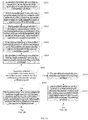
FIG. 4 is a schematic flowchart of a calibration method based on a dead reckoning technology according to a first embodiment of the present invention; -
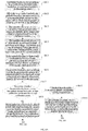
FIG. 5A andFIG. 5B is a schematic flowchart of a calibration method based on a dead reckoning technology according toEmbodiment 2 of the present invention; -
FIG. 6A andFIG. 6B is a schematic flowchart of a calibration method based on a dead reckoning technology according to Embodiment 3 of the present invention; -
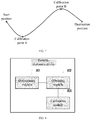
FIG. 7 is a schematic diagram of a target path set on an electronic map according to an embodiment of the present invention; and -
FIG. 8 is a schematic structural diagram of a portable electronic device according to an embodiment of the present invention. - The following clearly and completely describes the technical solutions in the embodiments of the present invention with reference to the accompanying drawings in the embodiments of the present invention. Apparently, the described embodiments are merely some but not all of the embodiments of the present invention.
- Now the embodiments are described to in detail, and examples of the embodiments are shown in the accompanying drawings. Many specific details are provided in the following detailed descriptions, so as to provide a full understanding of the present invention. However, it is obvious to a person skilled in the art that the present invention may be practiced without the specific details. In other cases, well-known methods, procedures, components, circuits, and networks are not described in detail, so that aspects of the embodiments are not unnecessarily made hard to understand.
- It should be understood that, although the terms such as "first" and "second" may be used to describe various elements in this specification, the elements should not be limited by the terms. The terms are merely used to distinguish one element from another element. For example, a first threshold may be named a second threshold, and similarly, a second threshold may be named a first threshold, without departing from the scope of the present invention. Both the first threshold and the second threshold are thresholds, but the first threshold and the second threshold may not be one threshold. In some scenarios, the first threshold and the second threshold may be one threshold though.
- The terms used in the description of the present invention in this specification are merely for the purpose of describing specific embodiments, and are not intended to limit the present invention. The terms "one", "a", and "this" of singular forms used in this specification and the appended claims of the present invention are also intended to include plural forms, unless otherwise specified in the context explicitly. It should be further understood that, the term "and/or" used in this specification indicates and includes any or all possible combinations of one or more items in associated listed items. It should be further understood that the term "include" and/or "comprise" used in this specification specifies presence of features, integers, steps, operations, elements, and/or components, with presence or addition of one or more other features, integers, steps, operations, elements, components, and/or their combinations not excluded.
- According to the context, the term "if' used in this specification may be interpreted as a meaning of "when" or "after" or "in response to determining" or "in response to detecting". Similarly, according to the context, the phrase "if it is determined that" or "if (a stated condition or event) is detected" may be interpreted as a meaning of "when it is determined that" or "in response to determining" or "when (a stated condition or event) is detected" or "in response to detecting (a stated condition or event)".
- An electronic device, a user interface configured for such a device, and an embodiment used for an associated procedure in which such a device is used are described. In some embodiments, the device is a portable communications device, such as a mobile phone, that further includes another function such as a personal digital assistant and/or music player function. An illustrative embodiment of a portable electronic device includes but is not limited to a portable electronic device using iOS®, Android®, Microsoft®, or another operating system. Another portable electronic device such as a laptop computer or a tablet computer provided with a touch-sensitive surface (for example, a touchscreen display and/or a touchpad) may be used. It should be further understood that in some embodiments, the device is not a portable communications device, but a desktop computer provided with a touch-sensitive surface (for example, a touchscreen display and/or a touchpad).
- An electronic device including a display and a touch-sensitive surface is described in the following discussion. However, it should be understood that the electronic device may include one or more other physical user interface devices, such as a physical keyboard, a mouse, and/or a joystick.
- The device generally supports various application programs, such as one or more of the following: a drawing application program, a presentation application program, a Word processing application program, a web page creating application program, a drive editing application program, a spreadsheet application program, a game application program, a phone application program, a video conference application program, an email application program, an instant messaging application program, an exercise support application program, a photograph management application program, a digital camera application program, a digital video camera application program, a network browsing application program, a digital music player application program, and/or a digital video player application program.
- Various application programs that can be executed on the device may use at least one common physical user interface device, such as a touch-sensitive surface. One or more functions of the touch-sensitive surface and corresponding information displayed on the device may be adjusted and/or changed from an application program to a next application program and/or may be adjusted and/or changed in a corresponding application program. In this way, a common physical architecture (for example, a touch-sensitive surface) of the device may support the various application programs by using a user interface that is visualized and clear for a user.
- Herein an embodiment of a portable electronic device provided with a touch-sensitive display is described.
FIG. 1A is a block diagram of a portableelectronic device 100 provided with a touch-sensitive display 112 according to some embodiments. The touch-sensitive display 112 is sometimes referred to as a "touchscreen" for convenience, or may be referred to as or called a touch-sensitive display system, or may be referred to as a display system provided with a touch-sensitive surface (touch-sensitive surface) and a display (display). Thedevice 100 may include a memory 102 (which may include one or more computer readable storage media), amemory controller 122, one or more processing units (CPU) 120, aperipheral interface 118, anRF circuit system 108, anaudio circuit system 110, aspeaker 111, amicrophone 113, an input/output (I/O)subsystem 106, anotherinput control device 116, and anexternal port 124. Thedevice 100 may include one or moreoptical sensors 164. These components may communicate with one another through one or more communications buses or signalbuses 103. - It should be understood that, the
device 100 is merely an example of a portable electronic device, and thedevice 100 may have more or fewer components than the shown components, may combine two or more components, or may have different configurations or layouts of these components. Components shown inFIG. 1A may be implemented in a form of hardware or software or using a combination of software and hardware, and include one or more signal processing and/or application-specific integrated circuits. - The
memory 102 may include a high-speed random access memory, and may further include a nonvolatile memory, such as one or more disk storage devices, a flash memory device, or another nonvolatile solid-state memory device. Access of other components (such as theCPU 120 and the peripheral interface 118) of thedevice 100 to thememory 102 may be controlled by thememory controller 122. - The
peripheral interface 118 may be configured to couple input and output peripherals of the device to theCPU 120 and thememory 102. The one ormore processors 120 run or execute various software programs and/or instruction sets that are stored in thememory 102, so as to execute various functions of thedevice 100 and process data. In some embodiments, the one ormore processors 120 include an image signal processor and a dual-core or multi-core processor. For example, thememory 102 stores program code, and theprocessor 120 reads the program code in thememory 102 to execute the following operations: - determining, according to a dead reckoning technology, coordinates of a current position of the portable electronic device, a track parameter value at the current position, and a motion direction at the current position, where the track parameter value includes any one of a curvature change rate, a curvature radius change rate, a curvature, or a curvature radius, the portable electronic device moves on a preset target path, and at least two calibration points are set on the target path;
- if the motion direction is from a first calibration point to a second calibration point, obtaining coordinates of the second calibration point; and
- when it is detected that the track parameter value at the current position meets a preset calibration condition, correcting the coordinates of the current position to the coordinates of the second calibration point.
- In some embodiments, the
peripheral interface 118, theCPU 120, and thecontroller 122 may be implemented on a single chip, such as achip 104. In some other embodiments, they may be implemented on independent chips. - The RF (radio frequency)
circuit system 108 receives and sends RF signals, which are also called electromagnetic signals. TheRF circuit system 108 converts electrical signals into electromagnetic signals/converts electromagnetic signals into electrical signals, and communicates with a communications network and another communications device using the electromagnetic signals. TheRF circuit system 108 may include a well-known circuit system configured to execute these functions. The well-known circuit system includes but is not limited to an antenna system, an RF transceiver, one or more amplifiers, a tuner, one or more oscillators, a digital signal processor, a codec chipset, a subscriber identity module (SIM) card, a memory, and the like. TheRF circuit system 108 may communicate with a network and another device by means of wireless communication. The network is, for example, the Internet (also referred to as the World Wide Web (WWW)), an intranet, and/or a wireless network (such as a cellular phone network, a wireless local area network (LAN), and/or a metropolitan area network (MAN)). In wireless communication, any type of multiple communications standards, protocols, and technologies may be used, including but not limited to the Global System for Mobile Communications (GSM), Enhanced Data rates for GSM Evolution (EDGE), High Speed Downlink Packet Access (HSDPA), High Speed Uplink Packet Access (HSUPA), Wideband Code Division Multiple Access (W-CDMA), Code Division Multiple Access (CDMA), Time Division Multiple Access (TDMA), Bluetooth, Wireless Fidelity (Wi-Fi) (such as IEEE 802.11a, IEEE 802.11b, IEEE 802.11g, and/or IEEE 802.11n), the Voice over Internet Protocol (VoIP), Wi-MAX, an email protocol (such as the Internet Message Access Protocol (IMAP) and/or Post Office Protocol (POP)), instant messaging (such as the Extensible Messaging and Presence Protocol (XMPP), SIP for Instant Messaging and Presence Leveraging Extensions (SIMPLE), and the Instant Messaging and Presence Service (IMPS)), and/or the short message service (SMS), or any other appropriate communications protocol, including a communications protocol that has not been developed upon the date when this document is filed. - The
audio circuit system 110, thespeaker 111, and themicrophone 113 provide an audio interface between a user and thedevice 100. Theaudio circuit system 110 receives audio data from theperipheral interface 118, converts the audio data into an electrical signal, and transmits the electrical signal to thespeaker 111. Thespeaker 111 converts the electrical signal into an acoustic wave audible to a human being. Theaudio circuit system 110 further receives an electrical signal that is obtained, by conversion according to an acoustic wave, by themicrophone 113. Theaudio circuit system 110 converts the electrical signal into audio data, and transmits the audio data to theperipheral interface 118 for processing. The audio data may be retrieved from and/or transmitted to thememory 102 and/or theRF circuit system 108 by theperipheral interface 118. In some embodiments, theaudio circuit system 110 further includes a headset jack (for example, 212 inFIG. 2 ). The headset jack provides an interface between theaudio circuit system 110 and a removable audio input/output peripheral. The peripheral is, for example, an output-only earphone or a headset provided with both an output (such as a single-earpiece or double-earpiece earphone) and an input (such as a microphone). - The I/
O subsystem 106 couples the input/output peripheral of thedevice 100, such as thetouchscreen 112 and the anotherinput control device 116, to theperipheral interface 118. The I/O subsystem 106 may include adisplay controller 156 and one ormore input controllers 160 applied to the another input control device. The one ormore input controllers 160 receive electrical signals from the anotherinput control device 116/sends electrical signals to the anotherinput control device 116. The anotherinput control device 116 may include a physical button (such as a push button or a rocker button), a dial pad, a slider switch, a joystick, a click wheel, or the like. In some alternative embodiments, theinput controller 160 may be coupled to (or not coupled to) any one of the following: a keyboard, an infrared port, a USB port, or a pointer device such as a mouse. The one or more buttons (for example, 208 inFIG. 2 ) may include an up/down button configured to control volume of thespeaker 111 and/or themicrophone 113. The one or more buttons may include a push button (for example, 206 inFIG. 2 ). - The touch-
sensitive display 112 provides an input interface and an output interface between the device and a user. Thedisplay controller 156 receives electrical signals from thetouchscreen 112 and/or sends electrical signals to thetouchscreen 112. Thetouchscreen 112 displays visual output to the user. The visual output may include graphics, text, an icon, a video, and any combination thereof (collectively referred to as "graphics"). In some embodiments, some or all visual output may be corresponding to a user interface object. - The
touchscreen 112 is provided with a touch-sensitive surface, a sensor, or a sensor group that receives input from a user based on the sense of touch and/or touch contact. Thetouchscreen 112 and the display controller 156 (together with any associated module and/or instruction set in the memory 102) detect contact (and any movement or interruption of the contact) on thetouchscreen 112, and convert the detected contact into interaction with a user interface object (such as one or more softkeys, icons, web pages, or images) that is displayed on thetouchscreen 112. In an illustrative embodiment, a contact point between thetouchscreen 112 and the user is corresponding to a finger of the user. - An LCD (liquid crystal display) technology, an LPD (light emitting polymer display) technology, or an LED (light emitting diode) technology may be used for the
touchscreen 112. However, in another embodiment, another display technology may be used. Thetouchscreen 112 and thedisplay controller 156 may detect contact and any movement or interruption of the contact, by using any technology of multiple currently known or to-be-developed future touch sensing technologies and another proximity sensor array or another component that is configured to determine one or more points in contact with thetouchscreen 112. The multiple touch sensing technologies include but are not limited to capacitive, resistive, infrared, and surface acoustic wave technologies. In an illustrative embodiment, a projected mutual capacitance sensing technology is used. - The
touchscreen 112 may have a video resolution greater than 100 dpi. In some embodiments, the touchscreen has a video resolution of about 160 dpi. A user may get in contact with thetouchscreen 112 by using any appropriate object or accessory such as a stylus or a finger. In some embodiments, a user interface is designed to mainly work with finger-based contact and gestures. This may come with lower accuracy compared with a stylus-based input because a finger has a larger contact area on the touchscreen. In some embodiments, the device translates a finger-based rough input into a precise pointer/cursor position or command, so as to execute a user-expected action. - In some embodiments, in addition to the touchscreen, the
device 100 may include a touchpad (not shown) configured to activate or deactivate a specific function. In some embodiments, the touchpad is a touch-sensitive region of the device. The touch-sensitive region is different from the touchscreen and does not display visual output. The touchpad may be a touch-sensitive surface separated from thetouchscreen 112, or an extension part of a touch-sensitive surface formed by the touchscreen. - The
device 100 further includes apower system 162 configured to supply power to various components. Thepower system 162 may include a power management system, one or more power supplies (such as a battery or an alternating current power supply (AC)), a recharging system, a power failure detection circuit, a power converter or inverter, a power status indicator (such as a light emitting diode (LED)), and any other component that is associated with power generation, management, and distribution in the portable electronic device. - The
device 100 may further include one or moreoptical sensors 164.FIG. 1A shows an optical sensor that is coupled to anoptical sensor controller 158 in the I/O subsystem 106. Theoptical sensor 164 may include a charge coupled device (CCD) or a complementary metal-oxide-semiconductor (CMOS) photoelectric transistor. Theoptical sensor 164 receives, from an environment, light projected by one or more lenses, and converts the light into data that represents an image. In combination with an imaging module 143 (also referred to as a camera module), theoptical sensor 164 may capture a static image or a video. In some embodiments, the one or more optical sensors are located at the rear of thedevice 100, and are opposite to thetouchscreen display 112 in the front of the device, so that the touchscreen display may be used as a viewfinder configured to collect a static image and/or a video image. In some embodiments, another one or more optical sensors are located in the front of the device, so that when watching another video conference participant on the touchscreen display, a user may obtain an image of the user at the same time for a video conference. - The
device 100 may further include one ormore proximity sensors 166.FIG. 1A shows theproximity sensor 166 that is coupled to theperipheral interface 118. In another option, theproximity sensor 166 may be coupled to theinput controller 160 in the I/O subsystem 106. In some embodiments, when the electronic device is put near to an ear of a user (for example, when the user is making a phone call), the proximity sensor is turned off, and thetouchscreen 112 is disabled. - The
device 100 may further include one ormore accelerometers 168.FIG. 1A shows theaccelerometer 168 that is coupled to theperipheral interface 118. In another option, theaccelerometer 168 may be coupled to theinput controller 160 in the I/O subsystem 106. In some embodiments, information is displayed on the touchscreen display in a vertical view or a horizontal view based on analysis on data that is received from the one or more accelerometers. Optionally, in addition to theaccelerometer 168, thedevice 100 further includes a magnetometer (not shown) and a GPS (or GLONASS or BeiDou or another global navigation system) receiver (not shown), which are configured to obtain position and orientation (for example, portrait or landscape) information of thedevice 100. - In some embodiments, software components stored in the
memory 102 include anoperating system 126, a communications module (or instruction set) 128, a contact/movement module (or instruction set) 130, a graphics module (or instruction set) 132, a text input module (or instruction set) 134, a global positioning system (GPS) module (or instruction set) 135, and an application program (or instruction set) 136. In addition, in some embodiments, thememory 102 stores a device/globalinternal status 157, as shown inFIG. 1A andFIG. 3 . The device/globalinternal status 157 includes any one or more of the following: an active application program status, used to indicate what application programs (if any) are currently active; a display status, used to indicate what application program, view, or other information occupies each region of thetouchscreen display 112; a sensor status, including information obtained from sensors of the device and theinput control device 116; and position information about a position and a posture of the device. - The operating system 126 (such as Darwin, RTXC, Linux, UNIX, OS X, Windows, Android, or an embedded operating system (for example, Vx Works)) includes various software components and/or drivers that are configured to control and manage general system tasks (such as memory management, storage device control, and power management), and facilitates communication between hardware and software components. In addition, in some embodiments, the
memory 102 stores adigital camera film 159 and adigital image pipeline 161. - The
communications module 128 facilitates communication with another device through one or moreexternal ports 124, and further includes various software components that are configured to process data received by theRF circuit system 108 and/or theexternal port 124. The external port 124 (such as a universal serial bus (USB) or a live wire) is suitable for direct coupling to another device or indirect coupling via a network (such as the Internet or a wireless LAN). In some embodiments, the external port is a multi-pin (for example, 30-pin) connector that is identical or similar to and/or compatible with a 30-pin connector applied to an iPod (a trademark of Apple Inc.) device. - The contact/
movement module 130 may detect contact with the touchscreen 112 (in combination with the display controller 156) or another touch-sensitive device (such as a touchpad or a physical click wheel). The contact/movement module 130 includes multiple software components configured to execute various operations related to contact detection, for example, determining whether contact has occurred (for example, detecting a finger press event), determining whether there is a movement of the contact and tracking the movement on the entire touch-sensitive surface (for example, detecting one or more finger drag events), and determining whether the contact has terminated (for example, detecting a finger lift event or contact interruption). The contact/movement module 130 receives contact data from the touch-sensitive surface. Determining a movement of a contact point may include: determining a rate (a quantity), a velocity (a quantity and a direction), and/or an acceleration (a quantity and/or direction change) of the contact point. The movement of the contact point is represented by a series of contact data. These operations may be applied to single-point contact (such as contact with one finger) or simultaneous contact at multiple points (such as "multi-point touch"/contact with multiple fingers). In some embodiments, the contact/movement module 130 and thedisplay controller 156 detect contact on the touchpad. - The contact/
movement module 130 may detect a gesture input of a user. Different gestures on the touch-sensitive surface have different contact patterns. Therefore, a gesture may be detected by detecting a specific contact pattern. For example, detecting a single-finger tap gesture includes: detecting a finger press event; and then detecting a finger lift (lift and leave) event in a position (for example, in a position of an icon) that is the same as a position in which the finger press event is detected (or in a basically same position). For another example, detecting a finger swipe gesture on the touch-sensitive surface includes: detecting a finger push event; then detecting one or more finger drag events; and then detecting a finger lift (lift and leave) event. - The
graphics module 132 includes multiple known software components configured to render and display graphics on thetouchscreen 112 and another display, and includes a component configured to change strength of the displayed graphics. As used in this specification, the term "graphics" includes any object that may be displayed to a user, including but not limited to text, a web page, an icon (such as a user interface object that includes a softkey), a digital image, a video, an animation, and the like. - In some embodiments, the
graphics module 132 stores to-be-used data to represent graphics. A corresponding code may be allocated to each piece of graphics. Thegraphics module 132 receives, from an application program or the like, one or more codes of graphics to be displayed as specified, and also receives coordinate data and other graphics attribute data when necessary; and then generates screen image data, and outputs the data to thedisplay controller 156. - The
text input module 134 that may be configured as a component of thegraphics module 132 provides a soft keyboard that is configured to input text in multiple application programs (such as acontacts 137, anemail 140, aninstant messaging 141, abrowser 147, and any other application program that requires text inputs). - The
GPS module 135 determines a position of the device and provides the information for use in various application programs (for example, providing the information for aphone 138 for position-based dialing, providing the information for acamera 143 as picture/video metadata, or providing the information for an application program that provides a position-based service, such as a weather desktop applet, a local yellow page desktop applet, or a map/navigation desktop applet). - The
application program 136 may include the following modules (or instruction sets) or a subset or superset thereof: - the contacts module 137 (sometimes also referred to as an address book or a contacts list);
- the
phone module 138; - a
video conference module 139; - the
email client module 140; - the instant messaging (IM)
module 141; - an
exercise support module 142; - the
camera module 143 configured for a static image and/or a video image; - an
image management module 144; - the
browser module 147; - a
calendar module 148; - a
desktop applet module 149, which may include any one or more of the following: the weather desktop applet 149-1, a stock market desktop applet 149-2, a calculator desktop applet 149-3, an alarm clock desktop applet 149-4, a dictionary desktop applet 149-5, another desktop applet obtained by a user, or a user-created desktop applet 149-6; - a desktop
applet creator module 150 that is configured to generate the user-created desktop applet 149-6; - a
search module 151; - a video and
music player module 152, which may include a video player module and a music player module; - a
memo module 153; - a
map module 154; - an
online video module 155; - a sound/
audio recorder module 163; and/or - a
notification module 165. - An example of another
application program 136 that may be stored in thememory 102 includes another text processing application program, another image editing application program, a drawing application program, a presentation application program, a JAVA-enabled application program, encryption, digital rights management, sound recognition, or sound reproduction. - In combination with the
touchscreen 112, thedisplay controller 156, thecontact module 130, thegraphics module 132, and thetext input module 134, thecontacts module 137 may be configured to manage an address book or a contacts list (for example, stored in an application programinternal status 192 of thecontacts module 137 in thememory 102 or a memory 370), including: adding a name to the address book; deleting a name from the address book; associating a phone number, an email address, a real-world address, or other information with a name; associating an image with a name; categorizing and sorting a name; providing a phone number or an email address to initiate and/or facilitate communication that is performed by using thephone 138, thevideo conference 139, theemail 140, or theIM 141; and the like. - In combination with the
RF circuit system 108, theaudio circuit system 110, thespeaker 111, themicrophone 113, thetouchscreen 112, thedisplay controller 156, thecontact module 130, thegraphics module 132, and thetext input module 134, thephone module 138 may be configured to input a character sequence that is corresponding to a phone number, access one or more phone numbers in theaddress book 137, modify a phone number that has been input, dial a corresponding phone number, connect a call, and disconnect or hang up when a call is completed. As described above, any one of multiple communications standards, protocols, and technologies may be used in wireless communication. - In combination with the
RF circuit system 108, theaudio circuit system 110, thespeaker 111, themicrophone 113, thetouchscreen 112, thedisplay controller 156, theoptical sensor 164, theoptical sensor controller 158, thecontact module 130, thegraphics module 132, thetext input module 134, thecontacts list 137, and thephone module 138, thevideo conference module 139 includes executable instructions that are used to initiate, connect, and terminate, according to user instructions, a video conference between a user and another one or more participants. - In combination with the
RF circuit system 108, thetouchscreen 112, thedisplay controller 156, thecontact module 130, thegraphics module 132, and thetext input module 134, theemail client module 140 includes executable instructions that are used to respond to user instructions to create, send, receive, and manage emails. In combination with theimage management module 144, theemail client module 140 makes it very easy to create and send an email that includes a static image or a video image that is shot by thecamera module 143. - In combination with the
RF circuit system 108, thetouchscreen 112, thedisplay controller 156, thecontact module 130, thegraphics module 132, and thetext input module 134, theinstant messaging module 141 includes executable instructions that are used to input a character sequence corresponding to an instant message, modify a character that is previously input, transmit a corresponding instant message (for example, using the short message service (SMS) or multimedia messaging service (MMS) protocol for a phone-based instant message, or using XMPP, SIMPLE, or IMPS for an Internet-based instant message), receive an instant message, and view a received instant message. In some embodiments, a transmitted and/or received instant message may include graphics, a photo, an audio file, a video file, and/or another attachment that is supported in MMS and/or the enhanced messaging service (EMS). As used in this specification, the "instant message" is both a phone-based message (such as a message sent using SMS or MMS) and an Internet-based message (such as a message sent using XMPP, SIMPLE, or IMPS). - In combination with the
RF circuit system 108, thetouchscreen 112, thedisplay controller 156, thecontact module 130, thegraphics module 132, thetext input module 134, theGPS module 135, themap module 154, and a music player module 146, theexercise support module 142 includes executable instructions that are used to: create an exercise (for example, one with a time, distance, and/or calorie consumption goal); communicate with an exercise sensor (a sports device); receive exercise sensor data; calibrate a sensor configured to monitor an exercise; select and play music for an exercise; and display, store, and transmit exercise data. - In combination with the
touchscreen 112, thedisplay controller 156, theoptical sensor 164, theoptical sensor controller 158, thecontact module 130, thegraphics module 132, the digital image pipeline 161 (which converts original data that comes from the optical sensor into a final image or video), and theimage management module 144, thecamera module 143 includes executable instructions that are used to capture a static image or a video (including a video stream) and store it into the memory 102 (for example, in the digital camera film 159), modify a feature of a static image or a video, or delete a static image or a video from the memory 102 (for example, from the digital camera film 159). - In combination with the
touchscreen 112, thedisplay controller 156, thecontact module 130, thegraphics module 132, thetext input module 134, and thecamera module 143, theimage management module 144 includes executable instructions that are used to arrange, modify (for example, edit), or manipulate in another manner, tag, delete, present (for example, in a digital slideshow or album), and store a static image and/or a video image (including a static image and/or a video image stored in the camera film 159). - In combination with the
RF circuit system 108, thetouchscreen 112, thedisplay system controller 156, thecontact module 130, thegraphics module 132, and thetext input module 134, thebrowser module 147 includes executable instructions that are used to browse the Internet (including searching, linking to, receiving, and displaying a web page or a part of the web page, and linking to an attachment of a web page or another file) according to user instructions. - In combination with the
RF circuit system 108, thetouchscreen 112, thedisplay system controller 156, thecontact module 130, thegraphics module 132, thetext input module 134, theemail client module 140, and thebrowser module 147, thecalendar module 148 includes executable instructions that are used to create, display, modify, and store a calendar or calendar-associated data (such as a calendar entry and a to-do task list) according to user instructions. - In combination with the
RF circuit system 108, thetouchscreen 112, thedisplay system controller 156, thecontact module 130, thegraphics module 132, thetext input module 134, and thebrowser module 147, thedesktop applet module 149 is a micro application program that may be downloaded and used by a user (such as the weather desktop applet 149-1, the stock market desktop applet 149-2, the calculator desktop applet 149-3, the alarm clock desktop applet 149-4, or the dictionary desktop applet 149-5), or a micro application program that is created by the user (such as the user-created desktop applet 149-6). In some embodiments, the desktop applet includes an HTML (Hypertext Markup Language) file, a CSS (cascading style sheet) file, and a JavaScript file. In some embodiments, the desktop applet includes an XML (Extensible Markup Language) file and a JavaScript file (such as the Yahoo! desktop applet). - In combination with the
RF circuit system 108, thetouchscreen 112, thedisplay system controller 156, thecontact module 130, thegraphics module 132, thetext input module 134, and thebrowser module 147, the desktopapplet creator module 150 may be used by a user to create a desktop applet (for example, transferring a user-specified part of a web page to the desktop applet). - In combination with the
touchscreen 112, thedisplay system controller 156, thecontact module 130, thegraphics module 132, and thetext input module 134, thesearch module 151 includes executable instructions that are used to search in thememory 102 according to user instructions for text, music, sound, image, video, and/or other files that match one or more search criteria (such as one or more search words specified by a user). - In combination with the
touchscreen 112, thedisplay system controller 156, thecontact module 130, thegraphics module 132, theaudio circuit system 110, thespeaker 111, theRF circuit system 108, and thebrowser module 147, the video andmusic player module 152 includes executable instructions that allow a user to download and play recorded music and another sound file that are stored in one or more file formats (such as an MP3 or AAC file), and executable instructions that are used to display, present, or play in another manner a video (for example, on thetouchscreen 112 or on an external display that is connected through the external port 124). In some embodiments, thedevice 100 may include functionality of an MP3 player. - In combination with the
touchscreen 112, thedisplay controller 156, thecontact module 130, thegraphics module 132, and thetext input module 134, thememo module 153 includes executable instructions that are used to create and manage a memo, a to-do task list, and the like according to user instructions. - In combination with the
RF circuit system 108, thetouchscreen 112, thedisplay system controller 156, thecontact module 130, thegraphics module 132, thetext input module 134, theGPS module 135, and thebrowser module 147, themap module 154 may be configured to receive, display, modify, and store a map and map-associated data (such as a driving route, data of a specific position, a nearby store, or another point of interest, and other position-based data) according to user instructions. - In combination with the
touchscreen 112, thedisplay system controller 156, thecontact module 130, thegraphics module 132, theaudio circuit system 110, thespeaker 111, theRF circuit system 108, thetext input module 134, theemail client module 140, and thebrowser module 147, theonline video module 155 includes instructions that allow a user to access, browse, receive (for example, streaming receiving and/or downloading), play (for example, on the touchscreen or on an external display that is connected through the external port 124), and send an email that has a link to a specific online video, and manage in another manner an online video that is in one or more file formats (such as H.264). In some embodiments, theinstant messaging module 141, instead of theemail client module 140, is configured to send a link that is to a specific online video. - In combination with the
touchscreen 112, thedisplay system controller 156, thecontact module 130, thegraphics module 132, theaudio circuit system 110, thespeaker 111, and themicrophone 113, the sound/audio recorder module 163 includes an executable instruction that allows a user to record audio (such as sound) in one or more file formats (such as an MP3 or AAC file), and executable instructions that are used to present or in another manner, play the recorded audio file. - In combination with the
touchscreen 112, thedisplay system controller 156, thecontact module 130, and thegraphics module 132, thenotification module 165 includes an executable instruction that displays a notification or an alert (such as an incoming message, an incoming call, a calendar event reminder, or an application program event) on thetouchscreen 112. - Each of the foregoing modules and application programs is corresponding to a set of executable instructions used to execute one or more of the foregoing functions and the methods introduced in this application (such as a computer-implemented method and another information processing method that are described in this specification). These modules (or instruction sets) do not need to be implemented as separate software programs, procedures, or modules. Therefore, various subsets of these modules may be combined or re-arranged in another manner in various embodiments. In some embodiments, the
memory 102 may store a subset of the foregoing modules and data structures. In addition, thememory 102 may store another module and data structure that are not described above. - In some embodiments, the
device 100 is such a device that operations of a set of functions predefined on the device are uniquely executed by the touchscreen and/or the touchpad. Using a touchscreen and/or a touchpad as a main input control device for an operation of thedevice 100 can reduce a quantity of physical input control devices (such as a push button and a dial pad) on thedevice 100. - The set of predefined functions that may be uniquely executed by the touchscreen and/or the touchpad includes navigation between user interfaces. In some embodiments, when the touchpad is touched by a user, the
device 100 is navigated from any user interface that may be displayed on thedevice 100 to a primary menu, a main menu, or a root menu. In such embodiments, the touchpad may be referred to as a "menu button". In some other embodiments, the menu button may be a physical push button or another physical input control device, instead of the touchpad. -
FIG. 1B is a block diagram of illustrative components configured for event processing according to some embodiments. In some embodiments, the memory 102 (inFIG. 1A ) or the memory 370 (inFIG. 3 ) include an event classifier 170 (for example, in the operating system 126) and a corresponding application program 136-1 (for example, any one of the foregoing application programs 137-151, 155, and 380-390). - The
event classifier 170 receives event information and determines an application program 136-1 to which the event information needs to be transferred and anapplication program view 191 of the application program 136-1. Theevent classifier 170 includes anevent monitor 171 and anevent scheduler module 174. In some embodiments, the application program 136-1 includes an application programinternal status 192. The application programinternal status 192 indicates a current application program view that is displayed on the touch-sensitive display 112 when the application program is active or is being executed. In some embodiments, the device/globalinternal status 157 is used by theevent classifier 170 to determine which one or more application programs are currently active, and the application programinternal status 192 is used by theevent classifier 170 to determine theapplication program view 191 that the event information needs to be transferred to. - In some embodiments, the application program
internal status 192 includes other information, such as one or more of the following: recovery information to be used when recovery of the application program 136-1 is executed, user interface status information that indicates information being displayed by the application program 136-1 or information ready to be displayed by the application program 136-1, a status queue that enables a user to return to a previous status or view of the application program 136-1, and a repetition/cancellation queue of a previous action taken by the user. - The event monitor 171 receives event information from the
peripheral interface 118. The event information includes information about a subevent (for example, a user touch on the touch-sensitive display 112, as a part of a multi-point touch gesture). Theperipheral interface 118 transmits information that theperipheral interface 118 receives from the I/O subsystem 106 or a sensor (such as the proximity sensor 166), theaccelerometer 168, and/or the microphone 113 (by using the audio circuit system 110). Information received by theperipheral interface 118 from the I/O subsystem 106 includes information that comes from the touch-sensitive display 112 or the touch-sensitive surface. - In some embodiments, the
event monitor 171 sends a request to theperipheral interface 118 at a predetermined interval. In response, theperipheral interface 118 transmits event information. In another embodiment, theperipheral interface 118 transmits event information only when there is a significant event (for example, receiving an input whose noise is higher than a predetermined noise threshold and/or receiving an input that exceeds predetermined duration). - In some embodiments, the
event classifier 170 further includes a hitview determining module 172 and/or an active eventrecognizer determining module 173. - When the touch-
sensitive display 112 displays more than one view, the hitview determining module 172 provides a software procedure used to determine that a subevent has occurred somewhere in one or more views. The view includes a control and another component that are visible to a user on the display. - Another aspect of a user interface associated with an application program is a set of views, which are sometimes referred to as application program views or user interface windows in this specification. In the views, information is displayed, and a touch-based gesture is generated. In the views, an application program view (of a corresponding application program) in which a touch is detected may be corresponding to a programming level in a programmed or view hierarchical structure of the application program. For example, in the views, a lowest-level view in which a touch is detected may be referred to as a hit view, and an event set recognized as a correct input may be at least partially determined based on the hit view of an initial touch that starts with a touch-based gesture. The hit
view determining module 172 receives information related to a subevent of a touch-based gesture. When the application program has multiple views that are organized in a hierarchical structure, the hitview determining module 172 recognizes the hit view as a lowest view that is in the hierarchical structure and that should process the subevent. In most cases, the hit view is a lowest-level view in which an initial subevent (that is, the first subevent in a subevent sequence that forms an event or a potential event) occurs. Once the hit view is recognized by the hit view determining module, the hit view generally receives all subevents related to the same touch or a same input source for which the hit view is recognized as a hit view. - The active event
recognizer determining module 173 determines which one or more views that are in the view hierarchical structure should receive a specific subevent sequence. In some embodiments, the active eventrecognizer determining module 173 determines that only the hit view should receive the specific subevent sequence. In another embodiment, the active eventrecognizer determining module 173 determines that all views including a physical position of the subevent are active involved views, and therefore determines that all the active involved views should receive the specific subevent sequence. In another embodiment, even if a touch subevent is completely restricted to a region associated with a specific view, a higher view in the hierarchical structure is still kept as an active involved view. - The
event scheduler module 174 schedules event information to an event recognizer (such as an event recognizer 180). In an embodiment including the active eventrecognizer determining module 173, theevent scheduler module 174 transfers the event information to the event recognizer determined by the active eventrecognizer determining module 173. In some embodiments, theevent scheduler module 174 stores the event information in an event queue, and the event information is retrieved by a correspondingevent receiver module 182. - In some embodiments, the
operating system 126 includes theevent classifier 170. Alternatively, the application program 136-1 includes theevent classifier 170. In another embodiment, theevent classifier 170 is an independent module, or is a part of another module (such as the contact/movement module 130) that is stored in thememory 102. - In some embodiments, the application program 136-1 includes multiple
event processing programs 190 and one or more application program views 191, each including instructions used to process a touch event that occurs in a corresponding view of a user interface of the application program. Eachapplication program view 191 of the application program 136-1 includes one ormore event recognizers 180. Generally, a correspondingapplication program view 191 includesmultiple event recognizers 180. In another embodiment, one or more of theevent recognizers 180 are a part of an independent module. The independent module is, for example, a user interface toolkit (not shown) or a higher-level object from which the application program 136-1 inherits a method and another feature. In some embodiments, a correspondingevent processing program 190 includes one or more of the following: adata updater 176, anobject updater 177, a GUI updater 178, and/orevent data 179 that is received from theevent classifier 170. Theevent processing program 190 may update the application programinternal status 192 by using or calling thedata updater 176, theobject updater 177, or the GUI updater 178. Alternatively, one or more of the application program views 191 include one or more corresponding event processing programs 190. In addition, in some embodiments, one or more of thedata updater 176, theobject updater 177, or the GUI updater 178 are included in a correspondingapplication program view 191. - A
corresponding event recognizer 180 receives event information (such as the event data 179) from theevent classifier 170 and identifies an event according to the event information. Theevent recognizer 180 includes anevent receiver 182 and anevent comparator 184. In some embodiments, theevent recognizer 180 further includes at least one subset of the following:metadata 183, and an event transfer instruction 188 (which may include a subevent transfer instruction). - The
event receiver 182 receives event information from theevent classifier 170. The event information includes information about a subevent, such as a touch or a touch movement. According to the subevent, the event information further includes other information, such as a position of the subevent. When the subevent involves a touch movement, the event information may further include a rate and a direction of the subevent. In some embodiments, an event includes rotating by the device from one orientation to another orientation (for example, rotating from a portrait orientation to a landscape orientation, or vice versa), and the event information includes corresponding information about a current orientation (also referred to as a device posture) of the device. - The
event comparator 184 compares the event information with a predefined event or subevent definition, and based on the comparison, determines an event or a subevent, or determines or updates a status of an event or a subevent. In some embodiments, theevent comparator 184 includes anevent definition 186. Theevent definition 186 includes a definition (such as a predefined subevent sequence) of an event, for example, an event 1 (187-1), an event 2 (187-2), or the like. In some embodiments, a subevent of an event 187 includes, for example, touch start, touch termination, touch movement, touch cancellation, and multi-point touch. In an example, a definition of the event 1 (187-1) is a double-tap on a displayed object. For example, the double-tap includes the first touch (touch start) with preset duration on the displayed object, the first lift (touch termination) with preset duration, the second touch (touch start) with preset duration on the displayed object, and the second lift (touch termination) with preset duration. In another example, a definition of the event 2 (187-2) is a drag of a displayed object. For example, the drag includes a touch (or contact) with preset duration on the displayed object, a movement of the touch on the touch-sensitive display 112, and a lift of the touch (touch termination). In some embodiments, the event further includes information used for one or more associated event processing programs 190. - In some embodiments, the
event definition 186 includes a definition used for an event about a corresponding user interface object. In some embodiments, theevent comparator 184 executes a hit test to determine which user interface object is associated with a subevent. For example, in an application program view in which three user interface objects are displayed on the touch-sensitive display 112, when detecting a touch on the touch-sensitive display 112, theevent comparator 184 executes a hit test to determine which one of the three user interface objects is associated with the touch (the subevent). If each displayed object is associated with a correspondingevent processing program 190, the event comparator determines, by using a result of the hit test, whichevent processing program 190 should be activated. For example, theevent comparator 184 selects an event processing program associated with an object and a subevent that trigger the hit test. - In some embodiments, a definition of a corresponding event 187 further includes a delay action. The delay action delays transfer of event information until it has been determined that a subevent sequence is indeed corresponding to or is indeed not corresponding to an event type of the event recognizer.
- When a
corresponding event recognizer 180 determines that a subevent string does not match any event in theevent definition 186, thecorresponding event recognizer 180 enters an event impossible, event failure, or event end state, and then thecorresponding event recognizer 180 ignores a subsequent subevent of the touch-based gesture. In this case, another event recognizer (if any) that is kept active for the hit view continues to track and process an ongoing subevent of the touch-based gesture. - In some embodiments, a
corresponding event recognizer 180 includesmetadata 183 that has a configurable attribute, flag, and/or list indicating how an event transfer system should execute transfer of a subevent of an active involved event recognizer. In some embodiments, themetadata 183 includes a configurable attribute, flag, and/or list indicating how event recognizers may interact with one another. In some embodiments, themetadata 183 includes a configurable attribute, flag, and/or list indicating a level of a change about whether a subevent is transferred to a view or a programmed hierarchical structure. - In some embodiments, when one or more specific subevents of an event are recognized, a
corresponding event recognizer 180 activates anevent processing program 190 associated with the event. In some embodiments, thecorresponding event recognizer 180 transfers event information associated with the event to theevent processing program 190. Activating theevent processing program 190 is different from sending (and delaying sending) a subevent to a corresponding hit view. In some embodiments, theevent recognizer 180 throws a flag associated with the recognized event, and theevent processing program 190 associated with the flag receives the flag and executes a predefined procedure. - In some embodiments, the
event transfer instruction 188 includes a subevent transfer instruction that transfers event information of a subevent but does not activate an event processing program. On the contrary, the subevent transfer instruction transfers the event information to an event processing program associated with a subevent string or transfers the event information to an active involved view. The event processing program associated with the subevent string or the active involved view receives the event information and executes a predetermined procedure. - In some embodiments, the
data updater 176 creates and updates data used in the application program 136-1. For example, thedata updater 176 updates a phone number used in thecontacts module 137 or a video file stored and used in a video player module 145. In some embodiments, theobject updater 177 creates and updates an object used in the application program 136-1. For example, theobject updater 177 creates a new user interface object or updates a position of a user interface object. The GUI updater 178 updates a GUI. For example, the GUI updater 178 prepares display information and sends the information to thegraphics module 132, so as to display the information on the touch-sensitive display. - In some embodiments, the
event processing program 190 includes or has access permission to thedata updater 176, theobject updater 177, and the GUI updater 178. In some embodiments, thedata updater 176, theobject updater 177, and the GUI updater 178 are included in a single module of a corresponding application program 136-1 orapplication program view 191. In another embodiment, thedata updater 176, theobject updater 177, and the GUI updater 178 are included in two or more software modules. - It should be understood that the foregoing discussion about user touch event processing on the touch-sensitive display is also applicable to another form of user input that uses an input device to operate the electronic device 100 (not all user inputs are initiated on the touchscreen), for example, a coordinated mouse movement and mouse button press (with or without one or more keyboard presses or holds), a user movement, tap, drag, scroll, or the like on the touchpad, a stylus input, a device movement, an oral instruction, a detected eye movement, a biological characteristic input, and/or any combination thereof. Such inputs may be used as inputs corresponding to subevents that define a to-be-recognized event.
-
FIG. 2 is a portableelectronic device 100 provided with atouchscreen 112 according to some embodiments. The touchscreen may display one or more graphics on a user interface (UI) 200. In this embodiment and other embodiments introduced below, a user may make a gesture on graphics by using, for example, one or more fingers 202 (not drawn in proportion in the figure) or one or more styluses 203 (not drawn in proportion in the figure), to select one or more of the graphics. In some embodiments, when the user interrupts contact with the one or more graphics, the one or more graphics are selected. In some embodiments, the gesture may include a single- or multi-time tap, a single- or multi-time slide (from left to right, from right to left, upwards, and/or downwards), and/or a flick (from right to left, from left to right, upwards, and/or downwards) of a finger that is already in contact with thedevice 100. In some embodiments, graphics are not selected upon unintentional contact with the graphics. For example, when a gesture corresponding to a selection is a tap, a corresponding application program is not selected upon a swipe gesture on an application program icon. - The
device 100 may further include one or more physical buttons, such as a "home screen" or amenu button 204. As described above, themenu button 204 may be configured to navigate to anyapplication program 136 in a set of application programs that may run on thedevice 100. Alternatively, in some embodiments, the menu button is implemented as a softkey on a GUI displayed on thetouchscreen 112. - In an embodiment, the
device 100 includes thetouchscreen 112, themenu button 204, apush button 206 configured to power on or power off the device and lock the device, (one or more)volume adjustment buttons 208, a subscriber identity module (SIM)card slot 210, aheadset jack 212, and an interconnection/chargeexternal port 124. Thepush button 206 may be configured to: power on or power off the device by pressing the button and holding the button in a pressed-down state for a predefined time interval; lock the device by pressing the button and releasing the button before the predefined time interval elapses; and/or unlock the device or initiate an unlock procedure. In an alternative embodiment, thedevice 100 may further receive, by using amicrophone 113, voice inputs used to activate or deactivate some functions. -
FIG. 3 is a block diagram of an illustrative electronic device provided with a display and a touch-sensitive surface according to some embodiments. Thedevice 300 does not need to be portable. In some embodiments, thedevice 300 is a laptop computer, a desktop computer, a tablet computer, a multimedia player device, a navigation device, an education device (such as a children's study toy), a game system, or a control device (such as a home or industrial controller). Thedevice 300 generally includes one or more processing units (CPU) 310, one or more networks orother communications interfaces 360, amemory 370, and one ormore communications buses 320 configured to interconnect these components. In some embodiments, theprocessing unit 310 includes an image signal processor and a dual-core or multi-core processor. Thecommunications bus 320 may include a circuit system (sometimes referred to as a chipset) that interconnects system components and controls communication between the system components. Thedevice 300 includes an input/output (I/O)interface 330 provided with adisplay 340. Thedisplay 340 is generally a touchscreen display. The I/O interface 330 may further include a keyboard and/or mouse (or another pointing device) 350, and atouchpad 355. Thedevice 300 further includes anoptical sensor 164 and anoptical sensor controller 158. Thememory 370 includes a high-speed random access memory, such as a DRAM, an SRAM, a DDR RAM, or another random access solid-state memory device; and may include a nonvolatile memory, such as one or more magnetic disk storage devices, optical disc storage devices, flash memory devices, or other nonvolatile solid-state storage devices. Optionally, thememory 370 may include one or more storage devices that are positioned from theCPU 310 in a remote manner. In some embodiments, thememory 370 stores programs, modules, and data structures similar to the programs, modules, and data structures that are stored in thememory 102 of the portable electronic device 100 (FIG. 1 ), or a subset of the programs, modules, and data structures. In addition, thememory 370 may store another program, module, and data structure that do not exist in thememory 102 of the portableelectronic device 100. For example, thememory 370 of thedevice 300 may store adrawing module 380, apresentation module 382, atext processing module 384, a webpage creating module 386, adrive editing module 388, and/or aspreadsheet module 390. However, thememory 102 of the portable electronic device 100 (FIG. 1 ) may not store these modules. - Each of the foregoing recognized components in
FIG. 3 may be stored in one or more memory devices that are mentioned above. Each of the foregoing recognized modules is corresponding to a set of instructions used to execute the foregoing functions. The foregoing recognized modules or programs (that is, instruction sets) do not need to be implemented as separate software programs, procedures, or modules. Therefore, various subsets of these modules may be combined or re-arranged in another manner in various embodiments. In some embodiments, thememory 370 may store a subset of the foregoing modules and data structures. In addition, thememory 370 may store another module and data structure that are not described above. - Now attention is shifted to an embodiment of a user interface ("UI") that can be implemented on the portable
electronic device 100. - Referring to
FIG. 4, FIG. 4 is a calibration method based on a dead reckoning technology according to an embodiment of the present invention. In this embodiment of the present invention, the method includes the following steps. - S401: A portable electronic device determines, according to the dead reckoning technology, coordinates of a current position of the portable electronic device, a track parameter value at the current position, and a motion direction at the current position.
- Specifically, the portable electronic device moves on a target path that is preset on an electronic map. The target path may be any path input by a user on the electronic map or any path planned by a navigation application program on the electronic map. At least two calibration points are set on the target path. The calibration points are used to represent points that are on the target path and at which a track parameter value suddenly changes. When the dead reckoning technology is a pedestrian dead reckoning technology, before moving from a start position of the target path, the portable electronic device first corrects coordinates of the start position and obtains initial step length information, so as to ensure input correctness of the dead reckoning technology and ensure positioning accuracy of the dead reckoning technology. The coordinates of the start position may be determined by using a method such as a GPS positioning method or a Wi-Fi positioning or Bluetooth positioning algorithm. This is not limited in the present invention. The initial step length information may be a preset default value or obtained by calculation in a previous positioning procedure. The portable electronic device obtains output data of a built-in sensor (for example, at least one of an accelerometer, a gyroscope, or a geomagnetic sensor) to obtain a motion track of the portable electronic device, and determines, by using the initial step length information and the dead reckoning technology, the coordinates of the current position of the portable electronic device on the electronic map. The coordinates of the current position herein are obtained by the portable electronic device according to the dead reckoning technology. The track parameter value at the current position of the portable electronic device is also obtained according to the dead reckoning technology. The track parameter value includes any one of a curvature change rate, a curvature radius change rate, a curvature, or a curvature radius. Each point on the motion track is corresponding to a curvature, a curvature radius, a curvature change rate, or a curvature radius change rate. A track parameter value used to extract the calibration points is preferably a curvature change rate or a curvature radius change rate.
- It may be understood that, the motion direction in this embodiment of the present invention is a relative motion direction and does not involve an absolute motion direction. For example, when the portable electronic device moves from A to B, the motion direction is recorded as from A to B; when the portable electronic device moves from B to A, the motion direction is recorded as from B to A. It should be noted that, for convenience of processing, the start position and a destination position of the target path are considered as calibration points in this embodiment of the present invention.
- S402: If the motion direction is from a first calibration point to a second calibration point, the portable electronic device obtains coordinates of the second calibration point.
- The motion direction indicates a motion trend of the portable electronic device and is not a precise geographic position direction. For example, when the portable electronic device moves between the first calibration point and the second calibration point, if the motion direction of the portable electronic device is from the first calibration point to the second calibration point, the first calibration point is a previous calibration point, and the second calibration point is a next calibration point; if the motion direction of the portable electronic device is from the second calibration point to the first calibration point, the second calibration point is a previous calibration point, and the first calibration point is a next calibration point. The portable electronic device may measure the motion direction by using a built-in gyroscope sensor. Coordinates of the first calibration point, the coordinates of the current position, and the coordinates of the second calibration point may be latitude and longitude coordinates, two-dimensional coordinates, or coordinates set on the electronic map. This is not limited in the present invention. Generally, the electronic map has stored coordinates of each position, and the coordinates may be directly called for determining coordinates of a position.
- S403: When detecting that the track parameter value at the current position meets a preset calibration condition, the portable electronic device corrects the coordinates of the current position to the coordinates of the second calibration point.
- Specifically, the coordinates of the current position that are obtained by the portable electronic device by using the dead reckoning technology increase as time increases. When the track parameter value at the current position of the portable electronic device meets the preset calibration condition, where the calibration condition is used to determine whether the portable electronic device has reached the second calibration point, if the calibration condition is met, the coordinates of the current position of the portable electronic device are corrected to the coordinates of the second calibration point. The portable electronic device moves on the target path. When at least two calibration points are set on the target path, the portable electronic device performs, according to the foregoing calibration method, calibration once each time the portable electronic device passes a subpath. In this way, a positioning error of the portable electronic device can be effectively reduced.
- In conclusion, by implementing this embodiment of the present invention, a portable electronic device moves on a preset target path, where calibration points are set on the target path. The portable electronic device obtains a current position by reckoning according to a dead reckoning technology. When a track parameter value at the current position meets a preset calibration condition, coordinates of the current position are corrected to coordinates of a next calibration point. In this way, a positioning error of the dead reckoning technology can be rectified at the calibration point, thereby avoiding accumulation of the positioning error and improving positioning accuracy of the dead reckoning technology.
- Referring to
FIG. 5A andFIG. 5B ,FIG. 5A andFIG. 5B is another schematic flowchart of a calibration method based on a dead reckoning technology according to an embodiment of the present invention. In this embodiment of the present invention, the method includes the following steps. - S501: A portable electronic device plans a target path on an electronic map according to a start position and a destination position.
- Specifically, the portable electronic device starts a map navigation program, displays the electronic map on a user interface, and obtains the target path according to the start position and the destination position and by using a preset path planning algorithm. The start position may be manually input by a user, or obtained by a user terminal by self-positioning according to a preset positioning algorithm, such as GPS positioning, Wi-Fi positioning, or Bluetooth positioning. It should be noted that, the target path may alternatively be any path input by the user on the electronic map. This is not limited in the present invention.
- S502: When the target path is continuous, the portable electronic device extracts as a calibration point a point on the target path at which a track parameter value is greater than a first threshold.
- Specifically, that the target path is smooth indicates that the target path has no point at which a sharp turn of the track parameter value occurs. If the target path is considered as a function curve in two-dimensional coordinates, a feature of the function curve is that the function curve is differentiable everywhere. The track parameter value includes any one of a curvature change rate, a curvature radius change rate, a curvature, or a curvature radius. Using the curvature change rate as an example, a procedure of extracting, by the portable electronic device, the point on the target path at which a track parameter value is greater than the first threshold may be: performing sampling on the target path according to a preset time interval to obtain multiple points, calculating curvature change rate values at the points, and using a point at which a curvature change rate value is greater than the first threshold as a calibration point. When there are consecutive points meeting a condition that a curvature change rate value is greater than the first threshold, the multiple consecutive calibration points are combined into one calibration point. A method for combination may be: using a point with a largest curvature change rate value in the multiple calibration points as the calibration point obtained after combination, or using a calibration point in a middle position in the multiple calibration points as the calibration point obtained after combination.
- It may be understood that, when the portable electronic device moves along the target path for the first time, the portable electronic device needs to calculate a track parameter value at each point on the target path, use a point at which a track parameter value is greater than the first threshold as a calibration point, and store coordinates of the calibration point. When the portable electronic device moves along the target path again, the portable electronic device does not need to calculate the track parameter value at each point, but directly calls the stored coordinates of the calibration point. It should be noted that, for convenience of processing, both the start position and the destination position are considered as calibration points in this embodiment.
- In some embodiments of the present invention, optionally, when the target path is non-smooth, a turning point on the target path is extracted as a calibration point.
- Specifically, that the target path is non-smooth indicates that there is a point the target path at which a sharp turn of the track parameter value occurs. If the target path is considered as a function curve in two-dimensional coordinates, the turning point is a non-differentiable point in the function curve. The target path may be obtained by combination of multiple line segments and/or multiple curves. This is not limited in the present invention. For example, a non-smooth target path includes three line segments, the three line segments intersect with one another to form two intersecting points, and the two intersecting points are used as calibration points of the target path. It should be noted that, the start position and the destination position of the target path are also considered as calibration points, and then the target path has four calibration points.
- When a track parameter value at an intersecting point of two adjacent line segments is calculated, an arc may be obtained by means of smoothing processing, and then a value of a curvature change rate or a value of a curvature radius change rate of the intersecting point is calculated.
- In some embodiments of the present invention, preferably, if the non-smooth target path includes multiple line segments, an included angle of every two adjacent line segments of the target path is calculated, and an intersecting point formed by two adjacent line segments whose angle value is greater than a preset angle threshold is selected as a calibration point. For example, assuming that the angle threshold is 90°, an intersecting point formed by two adjacent line segments may be considered as a calibration point of the target path only when an included angle of the two adjacent line segments is greater than or equal to 90°, so as to reduce a quantity of calibration points and reduce an amount of calculation for calibration.
- S503: The portable electronic device determines, according to the dead reckoning technology, coordinates of a current position, a track parameter value at the current position, and a motion direction at the current position.
- Specifically, the portable electronic device obtains output data of a built-in sensor (for example, at least one of an accelerometer, a gyroscope, or a geomagnetic sensor) to obtain a motion track, and determines, by using the dead reckoning technology, the coordinates of the current position of the portable electronic device on the electronic map. The coordinates of the current position herein are obtained by the portable electronic device according to the dead reckoning technology. When the dead reckoning technology is a pedestrian dead reckoning technology, step length information of the user needs to be further considered when the coordinates of the current position are determined. The step length information of the user is different in different motion modes. The step length information may be obtained by training on a path. The track parameter value at the current position of the portable electronic device is also obtained according to the dead reckoning technology. The track parameter value includes the curvature change rate or the curvature radius change rate. Each point on the motion track is corresponding to a value of the curvature change rate or a value of the curvature radius change rate.
- S504: If the motion direction is from a first calibration point to a second calibration point, the portable electronic device obtains coordinates of the second calibration point.
- Specifically, the motion direction indicates a motion trend. The portable electronic device moves on the target path. The calibration points on the target path divide the target path into multiple subpaths. A motion procedure of the portable electronic device is considered based on each subpath separately. It is assumed that the portable electronic device moves on a subpath between the first calibration point and the second calibration point. If the motion direction at the current position is oriented towards the first calibration point, it is determined that the first calibration point is a next calibration point, and the second calibration point is a previous calibration point; if the motion direction at the current position is oriented towards the second calibration point, the second calibration point is a next calibration point, and the first calibration point is a previous calibration point.
- S505: The portable electronic device detects that the track parameter value at the current position is greater than a second threshold.
- Specifically, the portable electronic device obtains the track parameter value that is of the current position and that is obtained by the dead reckoning technology. The track parameter value includes any one of a curvature change rate, a curvature radius change rate, a curvature, or a curvature radius. When it is detected that the track parameter value at the current position is greater than the second threshold, S506 is executed; otherwise, S503 continues to be executed.
- S506: The portable electronic device determines whether the portable electronic device has turned around between the first calibration point and the second calibration point.
- That the portable electronic device has turned around between the first calibration point and the second calibration point means: The motion direction at the current position of the portable electronic device is from the first calibration point to the second calibration point, and that the portable electronic device has turned around at a position before the current position is that the motion direction becomes from the second calibration point to the first calibration point. The portable electronic device may identify the motion direction by using a built-in sensor (an accelerometer, a gyroscope, or a geomagnetic sensor), and determine, according to the motion direction, whether the portable electronic device has turned around between the first calibration point and the second calibration point. If the portable electronic device has not turned around between the first calibration point and the second calibration point, S507 is executed; otherwise, S514 is executed.
- S507: The portable electronic device obtains a first path length between the current position and the second calibration point, and obtains a second path length between the first calibration point and the second calibration point.
- Specifically, the first path length indicates a length of a corresponding path between the current position and the second calibration point on the target path. The second path length indicates a length of a corresponding path between the first calibration point and the second calibration point on the target path. The path may be a straight line or a curve on the target path. A specific shape is determined according to a shape of the target path. The portable electronic device obtains the coordinates of the current position that are obtained according to the dead reckoning technology, and obtains the coordinates of the preset second calibration point on the target path. The first path length between the current position and the second calibration point may be obtained according to the coordinates of the current position, the coordinates of the second calibration point, and a geometrical shape parameter of the subpath between the current position and the second calibration point. The second path length between the first calibration point and the second calibration point on the target path may be obtained by using the foregoing method.
- S508: The portable electronic device divides the first path length by the second path length to obtain a proportion value.
- S509: The portable electronic device determines whether the obtained proportion value is less than a third threshold.
- The third threshold is less than 1. A smaller proportion value indicates that the portable mobile terminal is closer to the second calibration point.
- S510: The portable electronic device determines that the obtained proportion value is less than the third threshold, and obtains a track parameter value at the second calibration point.
- The track parameter value includes any one of a curvature change rate, a curvature radius change rate, a curvature, or a curvature radius. For obtainment of the track parameter at the second calibration point, reference may be made to that of the track parameter at the first calibration point. Details are not further described herein.
- Specifically, each point on the target path is corresponding to a track parameter value. The portable electronic device obtains the track parameter value at the current position and the track parameter value at the second calibration point.
- S511: The portable electronic device calculates a difference that is obtained by subtracting the track parameter value at the second calibration point from the track parameter value at the current position.
- S512: The portable electronic device determines whether the difference obtained by calculation is less than a fourth threshold.
- The fourth threshold is less than 1. A smaller difference obtained by calculation indicates that the portable mobile terminal is closer to the second calibration point. The third threshold and the fourth threshold may be equal or not equal.
- S513: The portable electronic device determines that the difference is less than the fourth threshold, and corrects the coordinates of the current position to the coordinates of the second calibration point.
- S514: The portable electronic device obtains coordinates of a turning position.
- Specifically, the portable electronic device moves on the subpath between the first calibration point and the second calibration point. The portable electronic device moves towards the second calibration point from a t1 time point to a t2 time point, and moves towards the first calibration point from the t2 time point to a t3 time point. The portable electronic device obtains, according to the dead reckoning technology, a current position corresponding to the t3 time point and a turning position corresponding to the t2 time point. Based on the current position, the first calibration point is a next calibration point, and the second calibration point is a previous calibration point.
- S515: The portable electronic device calculates a third path length between the current position and the turning position, and a fourth path length between the second calibration point and the turning position.
- Specifically, the third path length indicates a length of a corresponding path between the current position and the turning position on the target path. The fourth path length indicates a length of a corresponding path between the second calibration point and the turning position on the target path. The path may be a straight line or a curve. A specific shape is determined by the shape of the target path. The portable electronic device may obtain the third path length according to the coordinates of the current position, the coordinates of the turning position, and a geometrical shape parameter of the subpath between the current position and the turning position, where the coordinates are obtained according to the dead reckoning technology. The fourth path length between the second calibration point and the turning position may be obtained by using the foregoing method. Details are not further described herein.
- S516: The portable electronic device calculates a proportion value that is obtained by dividing the third path length by the fourth path length.
- S517: The portable electronic device determines whether the proportion value obtained by calculation is greater than a fifth threshold.
- The fifth threshold is a value less than 1. A greater proportion value obtained by calculation indicates that the portable mobile terminal is closer to the second calibration point.
- S518: The portable electronic device determines that the proportion value is greater than the fifth threshold, and obtains a track parameter value at the second calibration point.
- S519: The portable electronic device calculates a difference that is obtained by subtracting the second track parameter value from the track parameter value at the current position.
- S520: The portable electronic device determines whether the difference obtained by calculation is less than a sixth threshold.
- The sixth threshold is less than 1. A smaller difference obtained indicates that the portable electronic device is closer to the second calibration point.
- The first threshold and the second threshold may be equal or not equal. The third threshold, the fourth threshold, the fifth threshold, and the sixth threshold may be equal or not equal. A specific value is set as required.
- S521: The portable electronic device determines that the difference is less than the sixth threshold, and corrects the coordinates of the current position to the coordinates of the second calibration point.
- In some embodiments of the present invention, optionally, when the dead reckoning technology is the pedestrian dead reckoning technology, the current position is determined according to the step length information, and the step length information is updated. This embodiment of the present invention further includes: obtaining a path length of a path corresponding to at least two calibration points; collecting statistics on m motion statuses of the portable electronic device on the path and a step quantity corresponding to each of the m motion statuses; and obtaining new step length information according to the path length, the m motion statuses, and the step quantity corresponding to each motion status.
- Specifically, the step length information indicates a corresponding step length in different motion statuses. The motion statuses include a walking state, a jogging state, and a running state. The start position, a calibration point A, a calibration point B, and the destination position are set on the target path. The portable electronic device moves from the start position to the destination position on the target path. A subpath between the start position and the calibration point A is a
subpath 1. A subpath between the calibration point A and the calibration point B is asubpath 2. A subpath between the calibration point B and the destination position is a subpath 3. The portable electronic device may obtain coordinates of the start position by using GPS positioning, Wi-Fi positioning, or Bluetooth positioning; calculate a current position of the portable electronic device in real time by using default step length information and the dead reckoning technology; and correct coordinates of the current position to coordinates of the calibration point A when the track parameter value at the current position meets a preset calibration condition. The portable electronic device obtains a length of thesubpath 1, that is, L, and counts that there are m motion statuses on thesubpath 1. In the m motion statuses, the portable electronic device moves for y1, y2, ..., and yN steps by using step lengths of xl, x2, ..., and xN respectively. Then, an equation x1 ∗ y1 + x2 ∗ y2 + ... + xN ∗ yN = L holds. Solutions are found by using this equation and historical equations as simultaneous equations, to obtain a step length (that is, step length information) in each motion status. When the portable electronic device moves on thesubpath 2, the step length information obtained for thesubpath 1 is considered as new step length information for calculating a current position of the portable electronic device on thesubpath 2. - In some embodiments of the present invention, optionally, the method further includes: obtaining a motion distance that is obtained by calculation according to the dead reckoning technology; and when the motion distance is greater than a preset length and no point meeting the calibration condition is detected in the motion distance, stopping the calibration procedure and starting another positioning manner, such as satellite positioning, Wi-Fi positioning, or Bluetooth positioning.
- In some embodiments of the present invention, optionally, the portable electronic device has turned around once between the first calibration point and the second calibration point. After the turning around, the motion direction of the portable electronic device is from the second calibration point to the first calibration point. A processing procedure is: obtaining coordinates of a turning position, and calculating a third path length between the current position and the turning position, and a fourth path length between the first calibration point and the turning position; calculating a proportion value that is obtained by dividing the third path length by the fourth path length; determining whether the proportion value obtained by calculation is greater than a fifth threshold; if the proportion value is greater than the fifth threshold, obtaining a track parameter value at the first calibration point, and calculating a difference that is obtained by subtracting the track parameter value at the first calibration point from the track parameter value at the current position; and determining whether the difference obtained by calculation is less than a sixth threshold, and if the difference is less than the sixth threshold, correcting the coordinates of the current position to the coordinates of the second calibration point.
- For a specific principle, reference may be made to descriptions of S514-S521. Details are not further described herein.
- Referring to
FIG. 6A andFIG. 6B ,FIG. 6A andFIG. 6B is a calibration method based on a dead reckoning technology according to an embodiment of the present invention. In this embodiment of the present invention, the method includes the following steps. - S601: A portable electronic device plans a target path on an electronic map according to a start position and a destination position.
- Specifically, the portable electronic device starts a map navigation program, displays the electronic map on a user interface, and obtains the target path according to the start position and the destination position and by using a preset path planning algorithm. The start position may be manually input by a user, or obtained by a user terminal by self-positioning according to a preset positioning algorithm, such as GPS positioning, Wi-Fi positioning, or Bluetooth positioning. The target path may be any path input by the user on the electric map. This is not limited in the present invention.
- S602: When the target path is smooth, the portable electronic device extracts as a calibration point a point on the target path at which a track parameter value is greater than a first threshold.
- Specifically, that the target path is smooth indicates that the target path has no point at which a sharp turn of the track parameter value occurs. If the target path is considered as a function curve of a two-dimensional plane, points on the function curve are differentiable everywhere. The track parameter value includes any one of a curvature change rate, a curvature radius change rate, a curvature, or a curvature radius. For example, a procedure of extracting, by the portable electronic device, the point on the target path at which a track parameter value is greater than the first threshold may be: performing sampling on the target path according to a preset time interval to obtain multiple points, calculating curvature change rate values at the points, and using a point at which a curvature change rate value is greater than the first threshold as a calibration point. When there are consecutive points meeting a condition that a curvature change rate value is greater than the first threshold, the multiple consecutive calibration points are combined into one calibration point. A method for combination may be: using a point with a largest curvature change rate value in the multiple calibration points as the calibration point obtained after combination, or using a calibration point in a middle position in the multiple calibration points as the calibration point obtained after combination. It should be noted that, for convenience of processing, the start position and the destination position are considered as calibration points in this embodiment.
- S603: The portable electronic device calculates track parameter value ranges of subpaths on the target path that are obtained by division by calibration points.
- Specifically, multiple calibration points set on the target path divide the target path into multiple subpaths. A minimum track parameter value and a maximum the track parameter value that are corresponding to each subpath are obtained. A track parameter value range of each subpath is determined according to the minimum track parameter value and the maximum track parameter value. For example, the start position, a calibration point A, a calibration point B, and the destination position are sequentially arranged on the target path. The target path is divided into three subpaths, which are, respectively, a
subpath 1 between the start position and the calibration point A, asubpath 2 between the calibration point A and the calibration point B, and a subpath 3 from the calibration point B to the destination position. A track parameter value range of each of the foregoing three subpaths is calculated. A track parameter value in the track parameter value range is preferentially a curvature or a curvature radius. - S604: The portable electronic device determines, according to the dead reckoning technology, coordinates of a current position, a track parameter value at the current position, and a motion direction at the current position.
- Specifically, the portable electronic device obtains output data of a built-in sensor (such as an accelerometer, a gyroscope, or a geomagnetic sensor) to obtain a motion track. If the dead reckoning technology is a pedestrian dead reckoning technology, the coordinates of the current position of the portable electronic device on the electronic map are determined by using initial step length information and the dead reckoning technology. The coordinates of the current position herein are obtained by the portable electronic device according to the dead reckoning technology. The track parameter value at the current position of the portable electronic device is also obtained according to the dead reckoning technology. The track parameter value includes the curvature change rate or the curvature radius change rate. Each point on the motion track is corresponding to a curvature change rate or a curvature radius change rate.
- Coordinate ranges of subpaths on the target path are different. Therefore, the portable electronic device may obtain, by estimation according to the coordinates of the current position, a current residence subpath of the portable electronic device, and obtain, by estimation according to the motion direction, a next subpath. For example, it is determined, according to the coordinates of the current position, that the current subpath is the
subpath 1, and the motion direction is from the start position to the destination position. Then the next subpath is thesubpath 2. - S605: If the motion direction is from a first calibration point to a second calibration point, the portable electronic device obtains coordinates of the second calibration point.
- Specifically, the portable electronic device moves on the target path. The calibration points on the target path divide the target path into multiple subpaths. A motion procedure of the portable electronic device is considered based on each subpath separately. It is assumed that the portable electronic device moves on a subpath between the first calibration point and the second calibration point. If the motion direction at the current position is from the first calibration point to the second calibration point, it is determined that the first calibration point is a previous calibration point, and the second calibration point is a next calibration point; if the motion direction at the current position is from the second calibration point to the first calibration point, the second calibration point is a previous calibration point, and the first calibration point is a next calibration point.
- S606: The portable electronic device detects that the track parameter value at the current position is in a track parameter value range of a subpath whose start point is the second calibration point.
- Specifically, track parameter value ranges of two adjacent subpaths are different. When it is detected that the track parameter value at the current position is in a track parameter value range of a next subpath, S604 is executed.
- For example, the two adjacent subpaths are a subpath A and a subpath B, a track parameter value range of the subpath A is [x1, x2), and a track parameter value range of the subpath B is [x2, x3), where x1 < x2 < x3. When it is detected that a first track parameter value at the current position falls in the track parameter value range of the subpath B from the track parameter value range of the subpath A, S607 is executed; otherwise, S604 continues to be executed.
- S607: The portable electronic device determines whether the portable electronic device has turned around between the first calibration point and the second calibration point.
- Specifically, the portable electronic device may identify the motion direction by using a built-in sensor (an accelerometer, a gyroscope, or a geomagnetic sensor), and determine, according to the motion direction, whether the portable electronic device has turned around between the first calibration point and the second calibration point. If the portable electronic device has not turned around between the first calibration point and the second calibration point, S607 is executed; otherwise, S615 is executed.
- It should be noted that, in this embodiment of the present invention, the turning around means turning around only once on a subpath between two calibration points.
- S608: The portable electronic device obtains a first path length between the current position and the second calibration point, and obtains a second path length between the first calibration point and the second calibration point.
- Specifically, the first path length is a length of a corresponding path between the current position and the second calibration point on the target path. The second path length is a length of a corresponding path between the first calibration point and the second calibration point on the target path. A shape of the path depends on a length of the target path. The path may be a line segment or a curve. The portable electronic device obtains the coordinates of the current position that are obtained according to the dead reckoning technology, and obtains the coordinates of the preset second calibration point on the target path. The first path length between the current position and the second calibration point may be obtained according to the coordinates of the current position, the coordinates of the second calibration point, and a geometrical shape parameter of a subpath between the current position and the second calibration point. The second path length between the first calibration point and the second calibration point on the target path may be obtained by using the foregoing method.
- S609: The portable electronic device divides the first path length by the second path length to obtain a proportion value.
- S610: The portable electronic device determines whether the proportion value obtained by calculation is less than a third threshold.
- The third threshold is less than 1. A smaller proportion value indicates that the portable electronic device is closer to the second calibration point.
- S611: The portable electronic device obtains a track parameter value at the second calibration point, where the track parameter value includes any one of a curvature change rate, a curvature radius change rate, a curvature, or a curvature radius.
- S612: The portable electronic device calculates a difference that is obtained by subtracting the track parameter value at the second calibration point from the track parameter value at the current position.
- S613: The portable electronic device determines whether the difference obtained by calculation is less than a fourth threshold.
- The fourth threshold is less than 1. A smaller difference indicates that the portable electronic device is closer to the second calibration point.
- S614: The portable electronic device determines that the difference is less than the fourth threshold, and corrects the coordinates of the current position to the coordinates of the second calibration point.
- S615: The portable electronic device obtains coordinates of a turning position.
- Specifically, the portable electronic device moves on the subpath between the first calibration point and the second calibration point. The portable electronic device moves towards the second calibration point from a t1 time point to a t2 time point, and moves towards the first calibration point from the t2 time point to a t3 time point. The portable electronic device obtains, according to the dead reckoning technology, coordinates of a current position corresponding to the t3 time point and coordinates of a turning position corresponding to the t2 time point. Based on the current position, the first calibration point is a previous calibration point, and the second calibration point is a next calibration point.
- S616: The portable electronic device calculates a third path length between the current position and the turning position, and a fourth path length between the second calibration point and the turning position.
- Specifically, the third path length and the fourth path length are lengths of corresponding paths on the target path. The paths may be line segments or curves. A specific shape depends on the length of the target path. The portable electronic device may obtain the third path length according to the coordinates of the current position, the coordinates of the turning position, and a geometrical shape parameter of a subpath between the current position and the turning position, where the coordinates are obtained according to the dead reckoning technology. The fourth path length between the second calibration point and the turning position may be obtained by using the foregoing method. Details are not further described herein.
- S617: The portable electronic device calculates a proportion value that is obtained by dividing the third path length by the fourth path length.
- S618: The portable electronic device determines whether the proportion value obtained by calculation is greater than a fifth threshold.
- The fifth threshold is less than 1. A greater proportion value indicates that the portable electronic device is closer to the second calibration point.
- S619: The portable electronic device determines that the proportion value is greater than the fifth threshold, and obtains a track parameter value at the second calibration point.
- S620: The portable electronic device calculates a difference that is obtained by subtracting the second track parameter value from the track parameter value at the current position.
- S621: The portable electronic device determines whether the difference obtained by calculation is less than a sixth threshold.
- S622: The portable electronic device determines that the difference obtained by calculation is less than the sixth threshold, and corrects the coordinates of the current position to the coordinates of the second calibration point.
- The first threshold and the second threshold may be equal or not equal. The third threshold, the fourth threshold, the fifth threshold, and the sixth threshold may be equal or not equal. A specific value is set as required.
- Optionally, the portable electronic device has turned around once between the first calibration point and the second calibration point. After the turning around, the motion direction of the portable electronic device is from the second calibration point to the first calibration point. A processing procedure is: obtaining coordinates of a turning position, and calculating a third path length between the current position and the turning position, and a fourth path length between the first calibration point and the turning position; calculating a proportion value that is obtained by dividing the third path length by the fourth path length; determining whether the proportion value obtained by calculation is greater than a fifth threshold; if the proportion value is greater than the fifth threshold, obtaining a track parameter value at the first calibration point, and calculating a difference that is obtained by subtracting the track parameter value at the first calibration point from the track parameter value at the current position; and determining whether the difference obtained by calculation is less than a sixth threshold, and if the difference is less than the sixth threshold, correcting the coordinates of the current position to the coordinates of the second calibration point.
- For a specific principle, reference may be made to descriptions of S615-S622. Details are not described herein.
- Referring to
FIG. 8, FIG. 8 is a schematic structural diagram of a portable electronic device according to an embodiment of the present invention. In this embodiment of the present invention, the portable electronic device is configured to implement the method shown inFIG. 1 . The portable electronic device includes: a determiningmodule 801, an obtainingmodule 802, and acalibration module 803. - The determining
module 801 is configured to determine, according to a dead reckoning technology, coordinates of a current position of the portable electronic device, a track parameter value at the current position, and a motion direction at the current position. The track parameter value includes any one of a curvature change rate, a curvature radius change rate, a curvature, or a curvature radius. The portable electronic device moves on a preset target path. At least two calibration points are set on the target path. - The obtaining
module 802 is configured to: when the motion direction is from a first calibration point to a second calibration point, obtain coordinates of the second calibration point. - The
calibration module 803 is configured to: when it is detected that the track parameter value at the current position meets a preset calibration condition, correct the coordinates of the current position to the coordinates of the second calibration point. - This embodiment of the present invention is based on a same idea and brings a same technical effect, as the first method embodiment. For a specific principle, reference may be made to the description of the first method embodiment. Details are not further described herein.
- Optionally, in some embodiments of the present invention,
when the target path is smooth, a calibration point on the target path is a point on the target path at which a track parameter value is greater than a first threshold; or when the target path is non-smooth, a calibration point on the target path is a turning point on the target path. - Optionally, the calibration module is specifically configured to:
when it is detected that the track parameter value at the current position is greater than a second threshold, correct the coordinates of the current position to the coordinates of the second calibration point. - Optionally, the portable electronic device further includes:
- a configuration module, configured to: when the target path is smooth, determine track parameter value ranges of subpaths on the target path that are obtained by division by the calibration points, where the calibration point is a point on the target path at which a track parameter value is greater than a first threshold; and
- the calibration module is specifically configured to:
when it is detected that the track parameter value at the current position is in a track parameter value range of a subpath whose start point is the second calibration point, correct the coordinates of the current position to the coordinates of the second calibration point. - Optionally, the when it is detected that the track parameter value at the current position is greater than a second threshold, correcting, by the calibration module, the coordinates of the current position to the coordinates of the second calibration point includes:
- when it is detected that the track parameter value at the current position is greater than the second threshold and the portable electronic device has not turned around between the first calibration point and the second calibration point, obtaining a first path length between the current position and the second calibration point, and obtaining a path length between the first calibration point and the second calibration point;
- dividing the first path length by the second path length to obtain a proportion value;
- if the proportion value obtained by calculation is less than a third threshold, obtaining a track parameter value at the second calibration point;
- calculating a difference that is obtained by subtracting the track parameter value at the second calibration point from the track parameter value at the current position; and
- if the difference obtained by calculation is less than a fourth threshold, correcting the coordinates of the current position to the coordinates of the second calibration point.
- Optionally, the when it is detected that the track parameter value at the current position is greater than a second threshold, correcting, by the calibration module, the coordinates of the current position to the coordinates of the second calibration point includes:
- when it is detected that the track parameter value at the current position is greater than the second threshold and the portable electronic device has turned around once between the first calibration point and the second calibration point, obtaining coordinates of a turning position;
- calculating a third path length between the current position and the turning position, and a fourth path length between the second calibration point and the turning position;
- calculating a proportion value that is obtained by dividing the third path length by the fourth path length;
- if the proportion value obtained by calculation is greater than a fifth threshold, obtaining a track parameter value at the second calibration point;
- calculating a difference that is obtained by subtracting the track parameter value at the second calibration point from the track parameter value at the current position; and
- if the difference obtained by calculation is less than a sixth threshold, correcting the coordinates of the current position to the coordinates of the second calibration point.
- Optionally, the when it is detected that the track parameter value at the current position is in a track parameter value range of a subpath whose start point is the second calibration point, correcting, by the calibration module, the coordinates of the current position to the coordinates of the second calibration point includes:
- when it is detected that the track parameter value at the current position is in the track parameter value range of the subpath whose start point is the second calibration point and the portable electronic device has not turned around between the first calibration point and the second calibration point, obtaining a first path length between the current position and the second calibration point, and obtaining a second path length between the first calibration point and the second calibration point;
- dividing the first path length by the second path length to obtain a proportion value;
- if the proportion value obtained by calculation is less than a third threshold, obtaining a track parameter value at the second calibration point;
- calculating a difference that is obtained by subtracting the track parameter value at the second calibration point from the track parameter value at the current position; and
- if the difference is less than a fourth threshold, correcting the coordinates of the current position to the coordinates of the second calibration point.
- Optionally, the when it is detected that the track parameter value at the current position is in a track parameter value range of a subpath whose start point is the second calibration point, correcting, by the calibration module, the coordinates of the current position to the coordinates of the second calibration point includes:
- when it is detected that the track parameter value at the current position is in the track parameter value range of the subpath whose start point is the second calibration point and the portable electronic device has turned around once between the first calibration point and the second calibration point, obtaining coordinates of a turning position;
- calculating a third path length between the current position and the turning position, and a fourth path length between the second calibration point and the turning position;
- calculating a proportion value that is obtained by dividing the third path length by the fourth path length;
- if the proportion value obtained by calculation is greater than a fifth threshold, obtaining a track parameter value at the second calibration point;
- calculating a difference that is obtained by subtracting the track parameter value at the second calibration point from the track parameter value at the current position; and
- if the difference obtained by calculation is less than a sixth threshold, correcting the coordinates of the current position to the coordinates of the second calibration point.
- Optionally, the determining module is specifically configured to determine, according to a pedestrian dead reckoning technology and step length information, the coordinates of the current position of the portable electronic device, the track parameter value at the current position, and the motion direction at the current position; and
the portable electronic device further includes: - a length obtaining module, configured to obtain the path length between the first calibration point and the second calibration point;
- a statistics module, configured to collect statistics on m motion statuses of the portable electronic device between the first calibration point and the second calibration point, and a step quantity corresponding to each of the m motion statuses; and
- a step length calculation module, configured to obtain new step length information according to the m motion statuses, the step quantity corresponding to each of the m motion statuses, and the path length between the first calibration point and the second calibration point.
- This embodiment of the present invention is based on a same idea and brings a same technical effect, as the second and third method embodiments. For a specific principle, reference may be made to the descriptions of the second and third method embodiments. Details are not further described herein.
- In addition, a computer readable storage medium that stores one or more programs is further provided. The one or more programs include an instruction. When executed by a portable electronic device, the instruction instructs the portable electronic device to execute the method according to any one of the foregoing embodiments.
- A person of ordinary skill in the art may understand that all or some of the processes of the methods in the embodiments may be implemented by a computer program instructing relevant hardware. The program may be stored in a computer readable storage medium. When the program runs, the processes of the methods in the embodiments are performed. The foregoing storage medium may include: a magnetic disk, an optical disc, a read-only memory (Read-Only Memory, ROM), a random access memory (Random Access Memory, RAM), or the like.
Claims (5)
- A calibration method based on a dead reckoning technology performed by a portable electronic device, the method comprising:• determining, according to the dead reckoning technology, coordinates of a current position of the portable electronic device, a track parameter value at the current position, and a motion direction at the current position, wherein the track parameter value comprises any one of a curvature change rate, a curvature radius change rate, a curvature, or a curvature radius, wherein the portable electronic device moves on a preset target path, and at least two calibration points are set on the preset target path, wherein when the preset target path is smooth, each calibration point of the at least two calibration points on the preset target path is a point on the preset target path at which the track parameter value is greater than a first threshold; or when the preset target path is non-smooth, each calibration point of the at least two calibration points on the preset target path is a turning point on the preset target path (S401, S402);• if the motion direction is from a first calibration point to a second calibration point, obtaining coordinates of the second calibration point; and
when it is detected that the track parameter value at the current position is greater than a second threshold, correcting the coordinates of the current position to the coordinates of the second calibration point (S 403). - The method according to claim 1, wherein the when it is detected that the track parameter value at the current position is greater than the second threshold, correcting the coordinates of the current position to the coordinates of the second calibration point comprises:when it is detected that the track parameter value at the current position is greater than the second threshold and the portable electronic device has not turned around between the first calibration point and the second calibration point, obtaining a first path length between the current position and the second calibration point, and obtaining a path length between the first calibration point and the second calibration point;dividing the first path length by the second path length to obtain a proportion value;if the proportion value obtained by calculation is less than a third threshold, obtaining a track parameter value at the second calibration point;calculating a difference that is obtained by subtracting the track parameter value at the second calibration point from the track parameter value at the current position; andif the difference obtained by calculation is less than a fourth threshold, correcting the coordinates of the current position to the coordinates of the second calibration point.
- The method according to claim 1, wherein the when it is detected that the track parameter value at the current position is greater than the second threshold, correcting the coordinates of the current position to the coordinates of the second calibration point comprises:when it is detected that the track parameter value at the current position is greater than the second threshold and the portable electronic device has turned around once between the first calibration point and the second calibration point, obtaining coordinates of a turning position;calculating a third path length between the current position and the turning position, and a fourth path length between the second calibration point and the turning position;calculating a proportion value that is obtained by dividing the third path length by the fourth path length;if the proportion value obtained by calculation is greater than a fifth threshold, obtaining a track parameter value at the second calibration point;calculating a difference that is obtained by subtracting the track parameter value at the second calibration point from the track parameter value at the current position; andif the difference obtained by calculation is less than a sixth threshold, correcting the coordinates of the current position to the coordinates of the second calibration point.
- A portable electronic device (100, 300) configured to perform any of the methods according to claims 1 to 3.
- A computer readable storage medium that stores one or more programs, wherein the one or more programs comprise instructions, and when executed by a portable electronic device, the instructions cause the portable electronic device to execute the method according to any one of claims 1 to 3.
Applications Claiming Priority (1)
| Application Number | Priority Date | Filing Date | Title |
|---|---|---|---|
| PCT/CN2015/091330 WO2017054205A1 (en) | 2015-09-30 | 2015-09-30 | Calibration method based on dead reckoning technique, and portable electronic device |
Publications (3)
| Publication Number | Publication Date |
|---|---|
| EP3358300A1 EP3358300A1 (en) | 2018-08-08 |
| EP3358300A4 EP3358300A4 (en) | 2018-09-12 |
| EP3358300B1 true EP3358300B1 (en) | 2020-02-12 |
Family
ID=58422607
Family Applications (1)
| Application Number | Title | Priority Date | Filing Date |
|---|---|---|---|
| EP15905117.6A Active EP3358300B1 (en) | 2015-09-30 | 2015-09-30 | Calibration method based on dead reckoning technique, and portable electronic device |
Country Status (4)
| Country | Link |
|---|---|
| US (1) | US20180283873A1 (en) |
| EP (1) | EP3358300B1 (en) |
| CN (1) | CN107003132B (en) |
| WO (1) | WO2017054205A1 (en) |
Families Citing this family (10)
| Publication number | Priority date | Publication date | Assignee | Title |
|---|---|---|---|---|
| JP6693540B2 (en) * | 2018-07-31 | 2020-05-13 | 横河電機株式会社 | Device, method and program |
| CN111121743B (en) * | 2018-10-30 | 2023-11-24 | 阿里巴巴集团控股有限公司 | Position calibration method, device and electronic equipment |
| CN113554932B (en) * | 2020-04-23 | 2022-07-19 | 华为技术有限公司 | Track playback method and device |
| US20220113163A1 (en) * | 2020-10-08 | 2022-04-14 | Deere & Company | Methods and apparatus to automate multi-point inertial sensor calibration |
| CN114384567B (en) * | 2020-10-22 | 2025-08-12 | 华为技术有限公司 | Positioning method and related device |
| CN115526950B (en) * | 2021-06-25 | 2026-05-29 | 阿里巴巴创新公司 | Device screen horizontal calibration method and device, electronic device and program product |
| CN113932826B (en) * | 2021-10-13 | 2024-05-07 | 北京经纬恒润科技股份有限公司 | A method and system for optimizing vehicle navigation path |
| CN114399850B (en) * | 2021-12-27 | 2022-11-22 | 四川领歌智谷科技有限公司 | Attendance checking method based on voice and position recognition, electronic student identity card and storage medium |
| CN114518123B (en) * | 2022-02-24 | 2024-06-11 | 高德软件有限公司 | Information processing method |
| CN117470273B (en) * | 2022-07-21 | 2026-06-26 | 北京三快在线科技有限公司 | Navigation data calibration methods, devices, readable storage media, and electronic devices |
Family Cites Families (13)
| Publication number | Priority date | Publication date | Assignee | Title |
|---|---|---|---|---|
| US6024655A (en) * | 1997-03-31 | 2000-02-15 | Leading Edge Technologies, Inc. | Map-matching golf navigation system |
| DE19803662C2 (en) * | 1998-01-30 | 1999-12-02 | Siemens Ag | Navigation device and method for determining position using dead reckoning |
| KR100526571B1 (en) * | 2003-11-12 | 2005-11-04 | 삼성전자주식회사 | Off-board navigation system and method for calibrating error using the same |
| JP2006171456A (en) * | 2004-12-16 | 2006-06-29 | Denso Corp | Map data accuracy evaluation method, map data accuracy evaluation device, map data accuracy evaluation program, and corrected map data generation method |
| US8694251B2 (en) * | 2010-11-25 | 2014-04-08 | Texas Instruments Incorporated | Attitude estimation for pedestrian navigation using low cost mems accelerometer in mobile applications, and processing methods, apparatus and systems |
| US10330491B2 (en) * | 2011-10-10 | 2019-06-25 | Texas Instruments Incorporated | Robust step detection using low cost MEMS accelerometer in mobile applications, and processing methods, apparatus and systems |
| JP2014115093A (en) * | 2012-12-06 | 2014-06-26 | Casio Comput Co Ltd | Gps receiver and program |
| WO2015077514A1 (en) * | 2013-11-20 | 2015-05-28 | Certusview Technologies, Llc | Systems, methods, and apparatus for tracking an object |
| DE102014007794A1 (en) * | 2014-05-24 | 2014-10-23 | Daimler Ag | Method for operating a vehicle control system |
| CN104215238A (en) * | 2014-08-21 | 2014-12-17 | 北京空间飞行器总体设计部 | Indoor positioning method of intelligent mobile phone |
| US9884623B2 (en) * | 2015-07-13 | 2018-02-06 | GM Global Technology Operations LLC | Method for image-based vehicle localization |
| CN104977006A (en) * | 2015-08-11 | 2015-10-14 | 北京纳尔信通科技有限公司 | Indoor positioning method based on fuzzy theory and multi-sensor fusion |
| EP3136054B1 (en) * | 2015-08-28 | 2019-11-27 | HERE Global B.V. | Method, system, and computer program for determining a parametric site model from motion related sensor data |
-
2015
- 2015-09-30 WO PCT/CN2015/091330 patent/WO2017054205A1/en not_active Ceased
- 2015-09-30 EP EP15905117.6A patent/EP3358300B1/en active Active
- 2015-09-30 CN CN201580042885.4A patent/CN107003132B/en active Active
- 2015-09-30 US US15/763,749 patent/US20180283873A1/en not_active Abandoned
Non-Patent Citations (1)
| Title |
|---|
| None * |
Also Published As
| Publication number | Publication date |
|---|---|
| WO2017054205A1 (en) | 2017-04-06 |
| EP3358300A4 (en) | 2018-09-12 |
| EP3358300A1 (en) | 2018-08-08 |
| CN107003132A (en) | 2017-08-01 |
| CN107003132B (en) | 2021-05-04 |
| US20180283873A1 (en) | 2018-10-04 |
Similar Documents
| Publication | Publication Date | Title |
|---|---|---|
| AU2024200357B2 (en) | Devices, methods, and graphical user interfaces for wireless pairing with peripheral devices and displaying status information concerning the peripheral devices | |
| EP3358300A1 (en) | Calibration method based on dead reckoning technique, and portable electronic device | |
| DK180640B1 (en) | Devices and methods of measurement using augmented reality | |
| US11262905B2 (en) | Device, method, and graphical user interface for navigation of information in a map-based interface | |
| CN107533360B (en) | A display and processing method and related device | |
| US10642574B2 (en) | Device, method, and graphical user interface for outputting captions | |
| US20210281746A1 (en) | Devices, Methods, and Graphical User Interfaces for Assisted Photo-Taking | |
| TWI600322B (en) | Method for operating an electronic device with an integratd camera and related electronic device and non-transitory computer readable storage medium | |
| US20210279409A1 (en) | Device, method, and graphical user interface for sharing a content object in a document | |
| CN108317996B (en) | A method for determining floor, related equipment and system | |
| AU2016270042B2 (en) | Devices and methods for processing touch inputs over multiple regions of a touch-sensitive surface | |
| CN103218154B (en) | Apparatus, method and graphical user interface for selecting a view in a three-dimensional map based on gesture input | |
| US20130055119A1 (en) | Device, Method, and Graphical User Interface for Variable Speed Navigation | |
| US20130097556A1 (en) | Device, Method, and Graphical User Interface for Controlling Display of Application Windows | |
| CN106233237B (en) | A method and apparatus for processing new messages associated with an application | |
| CN107924264A (en) | For adjusting the equipment, method and graphic user interface of user interface object | |
| HK1222727A1 (en) | Navigation user interface | |
| CN107636594A (en) | Device and method for processing touch input | |
| CN110286836A (en) | Apparatus, method and graphical user interface for mobile application interface elements | |
| CN110100154B (en) | Apparatus, method and graphical user interface for launching an application | |
| CN106843708A (en) | Electronic equipment and method for deleting object | |
| HK1186237A (en) | Device, method, and graphical user interface for selection of views in a three-dimensional map based on gesture inputs | |
| HK1186237B (en) | Device, method, and graphical user interface for selection of views in a three-dimensional map based on gesture inputs | |
| HK1195642A (en) | Devices, methods, and graphical user interfaces for navigating and editing text |
Legal Events
| Date | Code | Title | Description |
|---|---|---|---|
| STAA | Information on the status of an ep patent application or granted ep patent |
Free format text: STATUS: THE INTERNATIONAL PUBLICATION HAS BEEN MADE |
|
| PUAI | Public reference made under article 153(3) epc to a published international application that has entered the european phase |
Free format text: ORIGINAL CODE: 0009012 |
|
| STAA | Information on the status of an ep patent application or granted ep patent |
Free format text: STATUS: REQUEST FOR EXAMINATION WAS MADE |
|
| 17P | Request for examination filed |
Effective date: 20180327 |
|
| AK | Designated contracting states |
Kind code of ref document: A1 Designated state(s): AL AT BE BG CH CY CZ DE DK EE ES FI FR GB GR HR HU IE IS IT LI LT LU LV MC MK MT NL NO PL PT RO RS SE SI SK SM TR |
|
| AX | Request for extension of the european patent |
Extension state: BA ME |
|
| A4 | Supplementary search report drawn up and despatched |
Effective date: 20180816 |
|
| RIC1 | Information provided on ipc code assigned before grant |
Ipc: G01C 21/14 20060101AFI20180809BHEP Ipc: G01C 22/00 20060101ALI20180809BHEP Ipc: G01C 25/00 20060101ALI20180809BHEP |
|
| DAV | Request for validation of the european patent (deleted) | ||
| DAX | Request for extension of the european patent (deleted) | ||
| REG | Reference to a national code |
Ref country code: DE Ref legal event code: R079 Ref document number: 602015047119 Country of ref document: DE Free format text: PREVIOUS MAIN CLASS: G01C0021120000 Ipc: G01C0021140000 |
|
| RIC1 | Information provided on ipc code assigned before grant |
Ipc: G01C 22/00 20060101ALI20190425BHEP Ipc: G01C 25/00 20060101ALI20190425BHEP Ipc: G01C 21/14 20060101AFI20190425BHEP |
|
| GRAP | Despatch of communication of intention to grant a patent |
Free format text: ORIGINAL CODE: EPIDOSNIGR1 |
|
| STAA | Information on the status of an ep patent application or granted ep patent |
Free format text: STATUS: GRANT OF PATENT IS INTENDED |
|
| INTG | Intention to grant announced |
Effective date: 20190904 |
|
| RIN1 | Information on inventor provided before grant (corrected) |
Inventor name: LU, CHENXI |
|
| GRAS | Grant fee paid |
Free format text: ORIGINAL CODE: EPIDOSNIGR3 |
|
| GRAA | (expected) grant |
Free format text: ORIGINAL CODE: 0009210 |
|
| STAA | Information on the status of an ep patent application or granted ep patent |
Free format text: STATUS: THE PATENT HAS BEEN GRANTED |
|
| AK | Designated contracting states |
Kind code of ref document: B1 Designated state(s): AL AT BE BG CH CY CZ DE DK EE ES FI FR GB GR HR HU IE IS IT LI LT LU LV MC MK MT NL NO PL PT RO RS SE SI SK SM TR |
|
| REG | Reference to a national code |
Ref country code: GB Ref legal event code: FG4D |
|
| REG | Reference to a national code |
Ref country code: CH Ref legal event code: EP |
|
| REG | Reference to a national code |
Ref country code: AT Ref legal event code: REF Ref document number: 1232707 Country of ref document: AT Kind code of ref document: T Effective date: 20200215 |
|
| REG | Reference to a national code |
Ref country code: IE Ref legal event code: FG4D |
|
| REG | Reference to a national code |
Ref country code: DE Ref legal event code: R096 Ref document number: 602015047119 Country of ref document: DE |
|
| PG25 | Lapsed in a contracting state [announced via postgrant information from national office to epo] |
Ref country code: NO Free format text: LAPSE BECAUSE OF FAILURE TO SUBMIT A TRANSLATION OF THE DESCRIPTION OR TO PAY THE FEE WITHIN THE PRESCRIBED TIME-LIMIT Effective date: 20200512 Ref country code: FI Free format text: LAPSE BECAUSE OF FAILURE TO SUBMIT A TRANSLATION OF THE DESCRIPTION OR TO PAY THE FEE WITHIN THE PRESCRIBED TIME-LIMIT Effective date: 20200212 Ref country code: RS Free format text: LAPSE BECAUSE OF FAILURE TO SUBMIT A TRANSLATION OF THE DESCRIPTION OR TO PAY THE FEE WITHIN THE PRESCRIBED TIME-LIMIT Effective date: 20200212 |
|
| REG | Reference to a national code |
Ref country code: LT Ref legal event code: MG4D |
|
| REG | Reference to a national code |
Ref country code: NL Ref legal event code: MP Effective date: 20200212 |
|
| PG25 | Lapsed in a contracting state [announced via postgrant information from national office to epo] |
Ref country code: LV Free format text: LAPSE BECAUSE OF FAILURE TO SUBMIT A TRANSLATION OF THE DESCRIPTION OR TO PAY THE FEE WITHIN THE PRESCRIBED TIME-LIMIT Effective date: 20200212 Ref country code: SE Free format text: LAPSE BECAUSE OF FAILURE TO SUBMIT A TRANSLATION OF THE DESCRIPTION OR TO PAY THE FEE WITHIN THE PRESCRIBED TIME-LIMIT Effective date: 20200212 Ref country code: GR Free format text: LAPSE BECAUSE OF FAILURE TO SUBMIT A TRANSLATION OF THE DESCRIPTION OR TO PAY THE FEE WITHIN THE PRESCRIBED TIME-LIMIT Effective date: 20200513 Ref country code: HR Free format text: LAPSE BECAUSE OF FAILURE TO SUBMIT A TRANSLATION OF THE DESCRIPTION OR TO PAY THE FEE WITHIN THE PRESCRIBED TIME-LIMIT Effective date: 20200212 Ref country code: IS Free format text: LAPSE BECAUSE OF FAILURE TO SUBMIT A TRANSLATION OF THE DESCRIPTION OR TO PAY THE FEE WITHIN THE PRESCRIBED TIME-LIMIT Effective date: 20200612 Ref country code: BG Free format text: LAPSE BECAUSE OF FAILURE TO SUBMIT A TRANSLATION OF THE DESCRIPTION OR TO PAY THE FEE WITHIN THE PRESCRIBED TIME-LIMIT Effective date: 20200512 |
|
| PG25 | Lapsed in a contracting state [announced via postgrant information from national office to epo] |
Ref country code: NL Free format text: LAPSE BECAUSE OF FAILURE TO SUBMIT A TRANSLATION OF THE DESCRIPTION OR TO PAY THE FEE WITHIN THE PRESCRIBED TIME-LIMIT Effective date: 20200212 |
|
| PG25 | Lapsed in a contracting state [announced via postgrant information from national office to epo] |
Ref country code: CZ Free format text: LAPSE BECAUSE OF FAILURE TO SUBMIT A TRANSLATION OF THE DESCRIPTION OR TO PAY THE FEE WITHIN THE PRESCRIBED TIME-LIMIT Effective date: 20200212 Ref country code: ES Free format text: LAPSE BECAUSE OF FAILURE TO SUBMIT A TRANSLATION OF THE DESCRIPTION OR TO PAY THE FEE WITHIN THE PRESCRIBED TIME-LIMIT Effective date: 20200212 Ref country code: RO Free format text: LAPSE BECAUSE OF FAILURE TO SUBMIT A TRANSLATION OF THE DESCRIPTION OR TO PAY THE FEE WITHIN THE PRESCRIBED TIME-LIMIT Effective date: 20200212 Ref country code: PT Free format text: LAPSE BECAUSE OF FAILURE TO SUBMIT A TRANSLATION OF THE DESCRIPTION OR TO PAY THE FEE WITHIN THE PRESCRIBED TIME-LIMIT Effective date: 20200705 Ref country code: LT Free format text: LAPSE BECAUSE OF FAILURE TO SUBMIT A TRANSLATION OF THE DESCRIPTION OR TO PAY THE FEE WITHIN THE PRESCRIBED TIME-LIMIT Effective date: 20200212 Ref country code: DK Free format text: LAPSE BECAUSE OF FAILURE TO SUBMIT A TRANSLATION OF THE DESCRIPTION OR TO PAY THE FEE WITHIN THE PRESCRIBED TIME-LIMIT Effective date: 20200212 Ref country code: SM Free format text: LAPSE BECAUSE OF FAILURE TO SUBMIT A TRANSLATION OF THE DESCRIPTION OR TO PAY THE FEE WITHIN THE PRESCRIBED TIME-LIMIT Effective date: 20200212 Ref country code: EE Free format text: LAPSE BECAUSE OF FAILURE TO SUBMIT A TRANSLATION OF THE DESCRIPTION OR TO PAY THE FEE WITHIN THE PRESCRIBED TIME-LIMIT Effective date: 20200212 Ref country code: SK Free format text: LAPSE BECAUSE OF FAILURE TO SUBMIT A TRANSLATION OF THE DESCRIPTION OR TO PAY THE FEE WITHIN THE PRESCRIBED TIME-LIMIT Effective date: 20200212 |
|
| REG | Reference to a national code |
Ref country code: DE Ref legal event code: R097 Ref document number: 602015047119 Country of ref document: DE |
|
| REG | Reference to a national code |
Ref country code: AT Ref legal event code: MK05 Ref document number: 1232707 Country of ref document: AT Kind code of ref document: T Effective date: 20200212 |
|
| PLBE | No opposition filed within time limit |
Free format text: ORIGINAL CODE: 0009261 |
|
| STAA | Information on the status of an ep patent application or granted ep patent |
Free format text: STATUS: NO OPPOSITION FILED WITHIN TIME LIMIT |
|
| 26N | No opposition filed |
Effective date: 20201113 |
|
| PG25 | Lapsed in a contracting state [announced via postgrant information from national office to epo] |
Ref country code: AT Free format text: LAPSE BECAUSE OF FAILURE TO SUBMIT A TRANSLATION OF THE DESCRIPTION OR TO PAY THE FEE WITHIN THE PRESCRIBED TIME-LIMIT Effective date: 20200212 Ref country code: IT Free format text: LAPSE BECAUSE OF FAILURE TO SUBMIT A TRANSLATION OF THE DESCRIPTION OR TO PAY THE FEE WITHIN THE PRESCRIBED TIME-LIMIT Effective date: 20200212 |
|
| PG25 | Lapsed in a contracting state [announced via postgrant information from national office to epo] |
Ref country code: SI Free format text: LAPSE BECAUSE OF FAILURE TO SUBMIT A TRANSLATION OF THE DESCRIPTION OR TO PAY THE FEE WITHIN THE PRESCRIBED TIME-LIMIT Effective date: 20200212 Ref country code: PL Free format text: LAPSE BECAUSE OF FAILURE TO SUBMIT A TRANSLATION OF THE DESCRIPTION OR TO PAY THE FEE WITHIN THE PRESCRIBED TIME-LIMIT Effective date: 20200212 |
|
| REG | Reference to a national code |
Ref country code: CH Ref legal event code: PL |
|
| REG | Reference to a national code |
Ref country code: BE Ref legal event code: MM Effective date: 20200930 |
|
| PG25 | Lapsed in a contracting state [announced via postgrant information from national office to epo] |
Ref country code: LU Free format text: LAPSE BECAUSE OF NON-PAYMENT OF DUE FEES Effective date: 20200930 |
|
| PG25 | Lapsed in a contracting state [announced via postgrant information from national office to epo] |
Ref country code: BE Free format text: LAPSE BECAUSE OF NON-PAYMENT OF DUE FEES Effective date: 20200930 Ref country code: CH Free format text: LAPSE BECAUSE OF NON-PAYMENT OF DUE FEES Effective date: 20200930 Ref country code: LI Free format text: LAPSE BECAUSE OF NON-PAYMENT OF DUE FEES Effective date: 20200930 Ref country code: IE Free format text: LAPSE BECAUSE OF NON-PAYMENT OF DUE FEES Effective date: 20200930 |
|
| PG25 | Lapsed in a contracting state [announced via postgrant information from national office to epo] |
Ref country code: TR Free format text: LAPSE BECAUSE OF FAILURE TO SUBMIT A TRANSLATION OF THE DESCRIPTION OR TO PAY THE FEE WITHIN THE PRESCRIBED TIME-LIMIT Effective date: 20200212 Ref country code: MT Free format text: LAPSE BECAUSE OF FAILURE TO SUBMIT A TRANSLATION OF THE DESCRIPTION OR TO PAY THE FEE WITHIN THE PRESCRIBED TIME-LIMIT Effective date: 20200212 Ref country code: CY Free format text: LAPSE BECAUSE OF FAILURE TO SUBMIT A TRANSLATION OF THE DESCRIPTION OR TO PAY THE FEE WITHIN THE PRESCRIBED TIME-LIMIT Effective date: 20200212 |
|
| PG25 | Lapsed in a contracting state [announced via postgrant information from national office to epo] |
Ref country code: MK Free format text: LAPSE BECAUSE OF FAILURE TO SUBMIT A TRANSLATION OF THE DESCRIPTION OR TO PAY THE FEE WITHIN THE PRESCRIBED TIME-LIMIT Effective date: 20200212 Ref country code: MC Free format text: LAPSE BECAUSE OF FAILURE TO SUBMIT A TRANSLATION OF THE DESCRIPTION OR TO PAY THE FEE WITHIN THE PRESCRIBED TIME-LIMIT Effective date: 20200212 Ref country code: AL Free format text: LAPSE BECAUSE OF FAILURE TO SUBMIT A TRANSLATION OF THE DESCRIPTION OR TO PAY THE FEE WITHIN THE PRESCRIBED TIME-LIMIT Effective date: 20200212 |
|
| PGFP | Annual fee paid to national office [announced via postgrant information from national office to epo] |
Ref country code: DE Payment date: 20250805 Year of fee payment: 11 |
|
| PGFP | Annual fee paid to national office [announced via postgrant information from national office to epo] |
Ref country code: GB Payment date: 20250807 Year of fee payment: 11 |
|
| PGFP | Annual fee paid to national office [announced via postgrant information from national office to epo] |
Ref country code: FR Payment date: 20250808 Year of fee payment: 11 |