EP3358248A1 - Planar light source and lighting device - Google Patents
Planar light source and lighting device Download PDFInfo
- Publication number
- EP3358248A1 EP3358248A1 EP16915914.2A EP16915914A EP3358248A1 EP 3358248 A1 EP3358248 A1 EP 3358248A1 EP 16915914 A EP16915914 A EP 16915914A EP 3358248 A1 EP3358248 A1 EP 3358248A1
- Authority
- EP
- European Patent Office
- Prior art keywords
- section
- planar light
- light source
- light emitting
- shielding
- Prior art date
- Legal status (The legal status is an assumption and is not a legal conclusion. Google has not performed a legal analysis and makes no representation as to the accuracy of the status listed.)
- Withdrawn
Links
- 238000005286 illumination Methods 0.000 claims abstract description 83
- 230000005291 magnetic effect Effects 0.000 claims description 26
- 230000005294 ferromagnetic effect Effects 0.000 claims description 14
- 239000011347 resin Substances 0.000 claims description 3
- 229920005989 resin Polymers 0.000 claims description 3
- 239000010410 layer Substances 0.000 description 22
- 230000003014 reinforcing effect Effects 0.000 description 22
- 230000036544 posture Effects 0.000 description 14
- 239000010432 diamond Substances 0.000 description 8
- 230000000149 penetrating effect Effects 0.000 description 8
- 238000003780 insertion Methods 0.000 description 6
- 230000037431 insertion Effects 0.000 description 6
- 230000002265 prevention Effects 0.000 description 6
- 244000025254 Cannabis sativa Species 0.000 description 4
- 235000012766 Cannabis sativa ssp. sativa var. sativa Nutrition 0.000 description 4
- 235000012765 Cannabis sativa ssp. sativa var. spontanea Nutrition 0.000 description 4
- 235000009120 camo Nutrition 0.000 description 4
- 235000005607 chanvre indien Nutrition 0.000 description 4
- 239000003302 ferromagnetic material Substances 0.000 description 4
- 239000011487 hemp Substances 0.000 description 4
- 239000000758 substrate Substances 0.000 description 4
- 239000011521 glass Substances 0.000 description 3
- 241000332371 Abutilon x hybridum Species 0.000 description 2
- 241000167854 Bourreria succulenta Species 0.000 description 2
- XEEYBQQBJWHFJM-UHFFFAOYSA-N Iron Chemical compound [Fe] XEEYBQQBJWHFJM-UHFFFAOYSA-N 0.000 description 2
- 241000277269 Oncorhynchus masou Species 0.000 description 2
- 241000207961 Sesamum Species 0.000 description 2
- 235000003434 Sesamum indicum Nutrition 0.000 description 2
- 235000019693 cherries Nutrition 0.000 description 2
- 229910003460 diamond Inorganic materials 0.000 description 2
- 238000009434 installation Methods 0.000 description 2
- 239000002346 layers by function Substances 0.000 description 2
- 239000002932 luster Substances 0.000 description 2
- 239000002184 metal Substances 0.000 description 2
- 229910052751 metal Inorganic materials 0.000 description 2
- 229910001092 metal group alloy Inorganic materials 0.000 description 2
- 239000011435 rock Substances 0.000 description 2
- 239000000853 adhesive Substances 0.000 description 1
- 230000001070 adhesive effect Effects 0.000 description 1
- 239000000470 constituent Substances 0.000 description 1
- 238000005034 decoration Methods 0.000 description 1
- 230000000694 effects Effects 0.000 description 1
- 229910052742 iron Inorganic materials 0.000 description 1
- 230000002093 peripheral effect Effects 0.000 description 1
- 230000001681 protective effect Effects 0.000 description 1
- 239000005315 stained glass Substances 0.000 description 1
- 238000002834 transmittance Methods 0.000 description 1
Images








Classifications
-
- F—MECHANICAL ENGINEERING; LIGHTING; HEATING; WEAPONS; BLASTING
- F21—LIGHTING
- F21S—NON-PORTABLE LIGHTING DEVICES; SYSTEMS THEREOF; VEHICLE LIGHTING DEVICES SPECIALLY ADAPTED FOR VEHICLE EXTERIORS
- F21S2/00—Systems of lighting devices, not provided for in main groups F21S4/00 - F21S10/00 or F21S19/00, e.g. of modular construction
- F21S2/005—Systems of lighting devices, not provided for in main groups F21S4/00 - F21S10/00 or F21S19/00, e.g. of modular construction of modular construction
-
- F—MECHANICAL ENGINEERING; LIGHTING; HEATING; WEAPONS; BLASTING
- F21—LIGHTING
- F21S—NON-PORTABLE LIGHTING DEVICES; SYSTEMS THEREOF; VEHICLE LIGHTING DEVICES SPECIALLY ADAPTED FOR VEHICLE EXTERIORS
- F21S8/00—Lighting devices intended for fixed installation
- F21S8/03—Lighting devices intended for fixed installation of surface-mounted type
- F21S8/033—Lighting devices intended for fixed installation of surface-mounted type the surface being a wall or like vertical structure, e.g. building facade
-
- F—MECHANICAL ENGINEERING; LIGHTING; HEATING; WEAPONS; BLASTING
- F21—LIGHTING
- F21V—FUNCTIONAL FEATURES OR DETAILS OF LIGHTING DEVICES OR SYSTEMS THEREOF; STRUCTURAL COMBINATIONS OF LIGHTING DEVICES WITH OTHER ARTICLES, NOT OTHERWISE PROVIDED FOR
- F21V11/00—Screens not covered by groups F21V1/00, F21V3/00, F21V7/00 or F21V9/00
-
- F—MECHANICAL ENGINEERING; LIGHTING; HEATING; WEAPONS; BLASTING
- F21—LIGHTING
- F21V—FUNCTIONAL FEATURES OR DETAILS OF LIGHTING DEVICES OR SYSTEMS THEREOF; STRUCTURAL COMBINATIONS OF LIGHTING DEVICES WITH OTHER ARTICLES, NOT OTHERWISE PROVIDED FOR
- F21V11/00—Screens not covered by groups F21V1/00, F21V3/00, F21V7/00 or F21V9/00
- F21V11/08—Screens not covered by groups F21V1/00, F21V3/00, F21V7/00 or F21V9/00 using diaphragms containing one or more apertures
-
- F—MECHANICAL ENGINEERING; LIGHTING; HEATING; WEAPONS; BLASTING
- F21—LIGHTING
- F21V—FUNCTIONAL FEATURES OR DETAILS OF LIGHTING DEVICES OR SYSTEMS THEREOF; STRUCTURAL COMBINATIONS OF LIGHTING DEVICES WITH OTHER ARTICLES, NOT OTHERWISE PROVIDED FOR
- F21V21/00—Supporting, suspending, or attaching arrangements for lighting devices; Hand grips
- F21V21/08—Devices for easy attachment to any desired place, e.g. clip, clamp, magnet
- F21V21/096—Magnetic devices
-
- H—ELECTRICITY
- H10—SEMICONDUCTOR DEVICES; ELECTRIC SOLID-STATE DEVICES NOT OTHERWISE PROVIDED FOR
- H10K—ORGANIC ELECTRIC SOLID-STATE DEVICES
- H10K50/00—Organic light-emitting devices
-
- H—ELECTRICITY
- H10—SEMICONDUCTOR DEVICES; ELECTRIC SOLID-STATE DEVICES NOT OTHERWISE PROVIDED FOR
- H10K—ORGANIC ELECTRIC SOLID-STATE DEVICES
- H10K50/00—Organic light-emitting devices
- H10K50/10—OLEDs or polymer light-emitting diodes [PLED]
-
- F—MECHANICAL ENGINEERING; LIGHTING; HEATING; WEAPONS; BLASTING
- F21—LIGHTING
- F21S—NON-PORTABLE LIGHTING DEVICES; SYSTEMS THEREOF; VEHICLE LIGHTING DEVICES SPECIALLY ADAPTED FOR VEHICLE EXTERIORS
- F21S8/00—Lighting devices intended for fixed installation
- F21S8/03—Lighting devices intended for fixed installation of surface-mounted type
- F21S8/032—Lighting devices intended for fixed installation of surface-mounted type the surface being a floor or like ground surface, e.g. pavement
-
- F—MECHANICAL ENGINEERING; LIGHTING; HEATING; WEAPONS; BLASTING
- F21—LIGHTING
- F21S—NON-PORTABLE LIGHTING DEVICES; SYSTEMS THEREOF; VEHICLE LIGHTING DEVICES SPECIALLY ADAPTED FOR VEHICLE EXTERIORS
- F21S8/00—Lighting devices intended for fixed installation
- F21S8/04—Lighting devices intended for fixed installation intended only for mounting on a ceiling or the like overhead structures
-
- F—MECHANICAL ENGINEERING; LIGHTING; HEATING; WEAPONS; BLASTING
- F21—LIGHTING
- F21V—FUNCTIONAL FEATURES OR DETAILS OF LIGHTING DEVICES OR SYSTEMS THEREOF; STRUCTURAL COMBINATIONS OF LIGHTING DEVICES WITH OTHER ARTICLES, NOT OTHERWISE PROVIDED FOR
- F21V15/00—Protecting lighting devices from damage
- F21V15/01—Housings, e.g. material or assembling of housing parts
-
- F—MECHANICAL ENGINEERING; LIGHTING; HEATING; WEAPONS; BLASTING
- F21—LIGHTING
- F21W—INDEXING SCHEME ASSOCIATED WITH SUBCLASSES F21K, F21L, F21S and F21V, RELATING TO USES OR APPLICATIONS OF LIGHTING DEVICES OR SYSTEMS
- F21W2121/00—Use or application of lighting devices or systems for decorative purposes, not provided for in codes F21W2102/00 – F21W2107/00
-
- F—MECHANICAL ENGINEERING; LIGHTING; HEATING; WEAPONS; BLASTING
- F21—LIGHTING
- F21Y—INDEXING SCHEME ASSOCIATED WITH SUBCLASSES F21K, F21L, F21S and F21V, RELATING TO THE FORM OR THE KIND OF THE LIGHT SOURCES OR OF THE COLOUR OF THE LIGHT EMITTED
- F21Y2105/00—Planar light sources
-
- F—MECHANICAL ENGINEERING; LIGHTING; HEATING; WEAPONS; BLASTING
- F21—LIGHTING
- F21Y—INDEXING SCHEME ASSOCIATED WITH SUBCLASSES F21K, F21L, F21S and F21V, RELATING TO THE FORM OR THE KIND OF THE LIGHT SOURCES OR OF THE COLOUR OF THE LIGHT EMITTED
- F21Y2115/00—Light-generating elements of semiconductor light sources
- F21Y2115/10—Light-emitting diodes [LED]
- F21Y2115/15—Organic light-emitting diodes [OLED]
-
- F—MECHANICAL ENGINEERING; LIGHTING; HEATING; WEAPONS; BLASTING
- F21—LIGHTING
- F21Y—INDEXING SCHEME ASSOCIATED WITH SUBCLASSES F21K, F21L, F21S and F21V, RELATING TO THE FORM OR THE KIND OF THE LIGHT SOURCES OR OF THE COLOUR OF THE LIGHT EMITTED
- F21Y2115/00—Light-generating elements of semiconductor light sources
- F21Y2115/20—Electroluminescent [EL] light sources
Definitions
- the present invention relates to a planar light source and an illumination apparatus that emit light in a planar shape.
- an organic EL panel has been used as a light source of an illumination apparatus (for example, Patent Document 1). Since the organic EL panel is a planar light source and has characteristics of being thin and lightweight, there are few restrictions on the installation place of the organic EL panel. Therefore, in recent years, application of the organic EL panel for a wall-surface illumination apparatus as well as for a ceiling illumination apparatus is considered.
- the wall-surface illumination apparatus is installed on a surface of a wall or the like.
- the ceiling illumination apparatus is installed on a ceiling.
- the wall-surface illumination apparatus used for a surface of a wall or the like not only functions as illumination but also is used as part of an interior decoration. Therefore, high design property is required.
- Patent Document 1 JP 2016-152157 A
- a conventional ceiling illumination apparatus used for a ceiling is installed such that light from a light emitting region of the organic EL panel is not shielded by another member in order to maximize light intensity of planar light. Therefore, the shape of the light emitting region is the irradiation range of the planar light as it is. For example, in the case of an organic EL panel in which the shape of the light source is rectangular, the shape of the light emitting region is also rectangular, and rectangular planar light is emitted. Therefore, if the conventional ceiling illumination apparatus is adopted as a wall-surface illumination apparatus as it is, illumination is uninteresting and gives monotonous impression when the apparatus is turned on, and further improvement of design property has been demanded.
- an object of the present invention is to provide a planar light source and an illumination apparatus which have higher design property than that of conventional ones.
- a planar light source including: a planar light emitting panel having a light emitting surface; and a decorative member covering the light emitting surface of the planar light emitting panel, wherein the light emitting surface includes: a light emitting region emitting light when the planar light source is turned on; and a non-light-emitting frame region surrounding the light emitting region, wherein the decorative member has a pattern forming section, and wherein the pattern forming section includes in a front view: a frame shielding section covering an entire area of the frame region; and a light-emission shielding section extending from the frame shielding section so as to divide the light emitting region into a plurality of regions.
- design property of the planar light emitting panel is higher than that of a conventional planar light emitting panel because light from the light emitting region is shielded by the pattern forming section of the decorative member, and light of a desired pattern is emitted.
- the frame shielding section hides the non-light-emitting frame region of the planar light emitting panel in the front view, the non-light-emitting frame region of the planar light emitting panel is not visually recognized from a user side. Therefore, the non-light-emitting frame region does not affect the external shape of the planar light emitting panel, and a desired appearance can be formed by the pattern forming section.
- the mechanical strength of the planar light emitting panel is reinforced by the frame shielding section surrounding the light emitting region of the decorative member and the light-emission shielding section dividing the light emitting region, warping or the like of the planar light emitting panel can be suppressed.
- the light-emission shielding section covers from 5% to 75% both inclusive of the light emitting region in a front view.
- the light-emission shielding section since the light-emission shielding section has a certain amount of area, it is possible to prevent trouble caused by a raise of panel temperature due to light-induced heat accumulated between the decorative member and the planar light emitting panel while sufficient mechanical strength is ensured.
- the decorative member includes a main body plate section having the pattern forming section, and a side-surface plate section bent from an end section of the main body plate section
- the planar light emitting panel includes: a planar light emitting tile; and a frame member protecting the planar light emitting tile, the frame member is made of resin and has elasticity, and part of the frame member is sandwiched by an end surface of the planar light emitting tile and the side-surface plate section.
- the frame member since part of the frame member having elasticity is sandwiched between the end surface of the planar light emitting tile and the side-surface plate section, the frame member can function as a buffer member and can absorb distortion due to thermal expansion of the planar light emitting tile. Therefore, even a planar light emitting tile having a thin glass panel as a supporting substrate is hard to break and has high safety.
- the planar light emitting panel constitutes one mirror surface together with the pattern forming section when the planar light source is turned off.
- the planar light emitting panel can be used as one mirror when the planar light source is turned off.
- the pattern forming section has at least two of the light-emission shielding sections having an identical width, the at least two of the light-emission shielding sections dividing the light emitting region into at least three regions in a front view.
- the at least two light-emission shielding sections reinforce the light emitting region such that the light-emission shielding sections divide the light emitting region into three or more regions, the at least two light-emission shielding sections can function better as a crosspiece and warping or the like of the planar light emitting panel can be further protected.
- the pattern forming section has a plate shape and includes a plurality of light transmitting holes that allow light from the light emitting region to pass through.
- the pattern forming section includes the plurality of light transmitting holes through which light from the light emitting region can pass, it is possible to emit light having a shape matching the shapes of the light transmitting holes. That is, by forming the shapes of the light transmitting holes into a desired pattern, a desired pattern can be lit up.
- the light-emission shielding section includes a shielding extending section extending with a longitudinal component and a lateral component in a front view.
- the shielding extending section since the shielding extending section extends with the lateral component and the longitudinal component, the shielding extending section can reinforce the planar light emitting panel against warping, deflection, and the like in the longitudinal direction and the lateral direction.
- some of the regions divided by the light-emission shielding sections have a different shielding rate, the shielding rate being defined as a ratio of an area where the pattern forming section is covering the light emitting region to an total area of the light emitting region.
- regions having different shielding rates are contained in the regions obtained by dividing the light emitting region by the light-emission shielding section, a difference in light intensity is generated in the region of the planar light source when the planar light source is turned on, and it is easy to form a pattern when the planar light source is arranged side by side with another planar light source.
- One aspect of the present invention is an illumination apparatus including: a first of the planar light source; and a second of the planar light source.
- the second of the planar light source has the pattern forming section that is different from the pattern forming section of the first of the planar light source.
- the first of the planar light source and the second of the planar light source are arranged to be adjacent to each other.
- the first of the planar light source and the second of the planar light source have a different shielding rate, the shielding rate being defined as a ratio of an area where the pattern forming section is covering the light emitting region to an total area of the light emitting region.
- the one planar light source and the other planar light source adjacent to each other have different shielding rates, a difference in light intensity of irradiation light is generated between the one planar light source and the other planar light source. Therefore, it is possible to form a pattern or a picture by using the difference in light intensity between the planar light sources, and to further improve design property.
- the pattern forming section of the first of the planar light source and the pattern forming section of the second of the planar light source form one pattern when the first of the planar light source and the second of the planar light source are turned on.
- one pattern can be formed by the difference in light intensity between the planar light sources, it is possible to further improve design property.
- One aspect of the present invention is an illumination apparatus including: the above-described planar light source; and a mounting member that can be fixed to a mounting surface.
- the mounting member has one of a magnetic force generating section and a ferromagnetic section, whereas the planar light source has the other of the magnetic force generating section and the ferromagnetic section on a back surface side, the magnetic force generating section and the ferromagnetic section forming a pair with each other.
- the planar light source is fixed to the mounting member by magnetic force generated between the magnetic force generating section and the ferromagnetic section.
- the planar light source is fixed to the mounting member by attractive force between the ferromagnetic section or the magnetic force generating section provided on the back surface of the planar light source and the magnetic force generating section or the ferromagnetic section of the mounting member. Therefore, the planar light source can be mounted to the mounting member without the light emitting surface being shielded by the ferromagnetic section and the magnetic force generating section.
- planar light source and the illumination apparatus of the present invention have higher design property than that of a conventional planar light source and a conventional illumination apparatus.
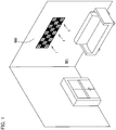
- an illumination apparatus 1 is mounted to a mounting surface 500 which is a surface of a wall, a ceiling, a floor, or the like, and illuminates a living space 501 side.
- the illumination apparatus 1 is arranged side by side with other plural illumination apparatuses 1 to constitute one illumination system.
- the illumination apparatus 1 includes one or more types of planar light sources 2 and a mounting member 3.
- the illumination apparatus 1 is configured by combining two types of planar light sources 2 (2a, 2b) including pattern forming sections 60 (60a, 60b) having different shapes.
- the planar light source 2a includes a planar light emitting panel 10 and a decorative member 11.
- the planar light emitting panel 10 is a light emitting panel which spreads in a planar shape and can emit planar light.
- the planar light emitting panel 10 is an organic EL panel and can emit diffused light.
- the planar light emitting panel 10 includes a light emitting surface 12 on one main surface side and power supply sections 13a, 13b on the other main surface side.
- a light emitting region 30 that actually emits light when the planar light source is turned on, and a non-light-emitting frame region 31 surrounding the light emitting region 30.
- the light emitting region 30 is a region which actually emits and radiates light when the planar light source is turned on.
- the light emitting region 30 When viewed from the front, the light emitting region 30 is an overlapping section of an anode layer built in the planar light emitting panel 10, an organic functional layer including an organic light emitting layer, and a cathode layer.
- the light emitting region 30 is a section corresponding to an organic EL device in which an anode layer, an organic functional layer, and a cathode Layer are laminated in this order. That is, in a case where the planar light source is turned on, in the light emitting region 30, a voltage is applied to the anode layer and the cathode layer, and therefore the organic light emitting layer emits and radiates light.
- the color of the anode layer or the cathode layer is reflected on the light emitting region 30 and the light emitting region 30 becomes a mirror surface when the planar light source is turned off.
- a transparent conductive oxide layer which is a transparent conductive layer is adopted as the anode layer, and a metal layer or a metal alloy layer having metallic luster is adopted as the cathode layer. That is, the color of the cathode layer is reflected on the light emitting region 30 according to the present embodiment and the light emitting region 30 becomes a mirror surface when the planar light source is turned off.
- the light emitting region 30 has a rectangular shape when viewed from the front and is provided at the center of the light emitting surface 12. In the present embodiment, the light emitting region 30 is a square region.
- a frame region 31 is a continuous non-light-emitting region extending along the edge of the planar light emitting panel 10 and surrounding the light emitting region 30. That is, the frame region 31 is located outside the light emitting region 30, and has a rectangular annular shape.
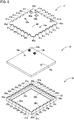
- the planar light emitting panel 10 includes a planar light emitting tile 15, a frame member 16, and a reinforcing plate 17.
- the planar light emitting tile 15 is a rectangular plate-shaped tile and is a thin plate-shaped tile.
- the planar light emitting tile 15 of the present embodiment is an organic EL tile in which a thin glass substrate is used as a supporting substrate and the above-described organic EL device is laminated on the thin glass substrate.
- the planar light emitting tile 15 includes the power supply sections 13a, 13b and position adjusting sections 14a, 14b on the back surface.
- the power supply sections 13a, 13b are terminals electrically connected to the anode layer and the cathode layer of the organic EL device, respectively, and are terminal sections protruding from the back surface of the planar light emitting tile 15.
- the position adjusting sections 14a, 14b are sections for adjusting the position of the planar light emitting tile 15 with respect to the reinforcing plate 17, and also are sections for adjusting the position of the planar light source 2a with respect to the mounting member 3. Specifically, the position adjusting sections 14a, 14b are projecting sections that projecting from the back surface of the planar light emitting tile 15.
- the frame member 16 is a protective frame for protecting the end surfaces of the planar light emitting tile 15, and is an elastic member made of resin.
- the frame member 16 is a frame having a rectangular annular shape when viewed from the front. As illustrated in Figs. 7 and 8 , the frame member 16 includes light-emitting-side covering sections 20a to 20d, end-surface-side covering sections 21a to 21d, and a back-surface-side covering section 22.
- the light-emitting-side covering sections 20a to 20d are sections covering a light emitting surface 12 side of the planar light emitting tile 15, and are sections belonging to the frame region 31 of the planar light emitting panel 10.
- the end-surface-side covering sections 21a to 21d are connecting wall sections that connect the end sections of the light-emitting-side covering sections 20a to 20d and the end section of the back-surface-side covering section 22, and are sections covering the end surfaces of the planar light emitting tile 15.
- the back-surface-side covering section 22 is a section that covers the back surface side of the planar light emitting tile 15.
- the back-surface-side covering section 22 includes a plurality of side projecting sections 25a to 25y and four corner engaging sections 26a to 26d.
- the side projecting sections 25a to 25y are sections bent from the end-surface-side covering sections 21a to 21d.
- the side projecting sections 25a to 25y are projecting pieces that project from the end-surface-side covering sections 21a to 21d toward the center when viewed from the back, and are fitting sections which can be fitted to side recessed sections 41a to 41y of the reinforcing plate 17.
- the side projecting sections 25a to 25y are arranged at intervals along each side of the planar light emitting panel 10.
- the side projecting sections 25, 25 belonging to an identical side are arranged at equal intervals.
- the corner engaging sections 26a to 26d are engaging sections that are provided at the corner sections of the back-surface-side covering section 22 and can engage with corner engaging sections 42a to 42d of the reinforcing plate 17, respectively.
- Each of the corner engaging sections 26a to 26d has a right triangle shape.
- the reinforcing plate 17 is a plate-shaped section covering the back surface side of the planar light emitting panel 10, and is a ferromagnetic section made of a ferromagnetic material. Specifically, the reinforcing plate 17 is an iron plate which is a ferromagnetic material.
- the reinforcing plate 17 includes a main body section 40, the side recessed sections 41a to 41y, and the corner engaging sections 42a to 42d.
- the main body section 40 is a rectangular section in front view, and includes position adjusting holes 43a, 43b and power-supply insertion holes 45a, 45b.
- the position adjusting holes 43a, 43b form a pair with the position adjusting sections 14a, 14b, respectively, and are sections for adjusting the position of the reinforcing plate 17 with respect to the planar light emitting tile 15.
- the position adjusting holes 43a, 43b are insertion holes through which the position adjusting sections 14a, 14b can be inserted, respectively, and are through holes penetrating the main body section 40 in the thickness direction of the main body section 40.
- the power-supply insertion holes 45a, 45b are through holes through which the power supply sections 13a, 13b of the planar light emitting tiles 15 can be inserted, and are through holes penetrating the main body section 40 in the thickness direction.
- the side recessed sections 41a to 41y are cutout sections extending inward from the edge of the main body section 40 when viewed from the back, and are fitting sections which can be fitted to the side projecting sections 25a to 25y of the frame member 16.
- the side recessed sections 41a to 41y are arranged at intervals along each side of the planar light emitting panel 10.
- the side recessed sections 41, 41 belonging to an identical side are arranged at equal intervals.
- the corner engaging sections 42a to 42d are engaging sections that are provided at the corner sections of the main body section 40 and can engage with the corner engaging sections 26a to 26d of the frame member 16, respectively.
- Each of the corner engaging sections 42a to 42d has a right triangle shape.
- the decorative member 11 is a member having specular gloss when viewed from the front.
- at least the front surface is formed of a metal or a metal alloy and has a metallic luster.
- the decorative member 11 includes a main body plate section 51, and side-surface plate sections 52a to 52d bent from the end section of the main body plate section 51.
- the main body plate section 51 is a decorative plate for covering the light emitting surface 12 side of the planar light emitting panel 10. As illustrated in Fig. 9 , the main body plate section 51 includes a pattern forming section 60a forming a specific pattern.
- the pattern forming section 60a is a section which is a muntin and has the kakuasa pattern (pattern of a hemp leaf surrounded by a square) in front view.
- the pattern forming section 60a includes a frame shielding section 61 covering the frame region 31, and a light-emission shielding section 62 covering part of the light emitting region 30.
- the frame shielding section 61 is a section overlapping with the entire area of the frame region 31 when viewed from the front, and is a section shielding light from the planar light emitting panel 10 side. That is, the frame shielding section 61 is composed of longitudinally extending sections 65, 66 and laterally extending sections 67, 68, and ends of the sections are connected to each other.
- the longitudinally extending sections 65, 66 and the laterally extending sections 67, 68 are continuous in a rectangular annular shape.
- the frame shielding section 61 includes frame intersections 70 to 73 where the longitudinally extending sections 65, 66 and the laterally extending sections 67, 68 intersect.
- the frame intersections 70 to 73 are corner intersections constituting corner sections of the pattern forming section 60a, and are formed at four corners, respectively.
- the light-emission shielding section 62 includes a lateral shielding section 75 horizontally crossing the light emitting region 30 of the planar light emitting panel 10, and a longitudinal shielding section 76 vertically crossing the light emitting region 30 of the planar light emitting panel 10 when viewed from the front.
- the lateral shielding section 75 includes planar shielding sections 80, 81, connecting shielding sections 82, 83, and a central intersection 89.
- the planar shielding sections 80, 81 are provided in the middle sections of the longitudinally extending sections 65, 66 and are semicircular sections extending from the longitudinally extending sections 65, 66 toward the central intersection 89. That is, each of the planar shielding sections 80, 81 has a curved end when viewed from the front.
- the planar shielding sections 80, 81 of the present embodiment are provided at the center in the extending direction of the longitudinally extending sections 65, 66.
- the “middle section” here means an intermediate section in the extending direction and refers to a section other than an end section. The same shall apply hereinafter.
- the connecting shielding section 82 is a section connecting the planar shielding section 80 and the central intersection 89
- the connecting shielding section 83 is a section connecting the central intersection 89 and the planar shielding section 80.
- the connecting shielding sections 82, 83 extend linearly in a lateral direction X.
- the longitudinal shielding section 76 includes planar shielding sections 85, 86, connecting shielding sections 87, 88, and the central intersection 89.
- the planar shielding sections 85, 86 are provided in the middle sections of the laterally extending sections 67, 68 and are semicircular sections extending from the laterally extending sections 67, 68 toward the central intersection 89.
- the planar shielding sections 85, 86 of the present embodiment are provided at the center of the laterally extending sections 67, 68.
- the connecting shielding section 87 is a section connecting the planar shielding section 85 and the central intersection 89
- the connecting shielding section 88 is a section connecting the central intersection 89 and the planar shielding section 86.
- the connecting shielding sections 87, 88 extend linearly in a longitudinal direction Y.
- the central intersection 89 is a section located at the center of the light-emission shielding section 62 and is a section where the lateral shielding section 75 and the longitudinal shielding section 76 intersect. That is, the central intersection 89 is a section where the connecting shielding sections 82, 83, 87, 88 merge.
- the light-emission shielding section 62 is divided into four first regions 77a to 77d by the lateral shielding section 75 and the longitudinal shielding section 76.
- Each of the first regions 77a to 77d is a rectangular region, and specifically has a square shape.
- the first regions 77a, 77b are in line symmetry with the first regions 77d, 77c with the lateral shielding section 75 as the axis of symmetry, and the first regions 77a, 77d are in line symmetry with the first regions 77b, 77c with the longitudinal shielding section 76 as the axis of symmetry. That is, the light-emission shielding section 62 is 4-fold rotational symmetrical with the central intersection 89 as the rotation axis when viewed from the front.
- second connecting shielding sections 90a to 90d shielding extending sections
- the first regions 77a to 77d are divided into two second regions 91a, 91b by the second connecting shielding sections 90a (90b to 90d), respectively.
- the second connecting shielding sections 90a to 90d are sections connecting the planar shielding sections 80, 81, 85, 86 and are sections connecting the planar shielding sections 80, 81, 85, 86 linearly in an oblique direction. That is, each of the second connecting shielding sections 90a to 90d has a lateral X component and a longitudinal Y component when viewed from the front.
- Both of the second regions 91a, 91b are right triangular regions, and are in line symmetry with respect to the second connecting shielding section 90a (90b to 90d) as the axis of symmetry.
- third connecting shielding sections 95a to 95c shielding extending sections
- the third connecting shielding sections 95a to 95c intersect at one intersection 96.
- Each of the second regions 91a, 91b is divided into three third regions 97a, 97b, 97c by the third connecting shielding sections 95a to 95c which each extend so as to be a bisector of each corner.
- Each of the third regions 97a, 97b, 97c is a triangular region.
- the third regions 97a, 97b, 97c are provided with a plurality of types of light transmitting holes 98a, 98b, 98c, respectively.
- the light transmitting holes 98a, 98b, 98c are holes through which light from the light emitting region 30 of the planar light emitting panel 10 can pass, and are through holes penetrating in the thickness direction of the main body plate section 51.
- Each of the light transmitting holes 98a, 98b, 98c has a triangular shape.
- the reinforcing plate 17 covers the back surface of the planar light emitting tile 15, and part of the power supply sections 13a, 13b passes through the power-supply insertion holes 45a, 45b and is exposed.
- Part of the front surface side of the planar light emitting tile 15 is covered with the light-emitting-side covering sections 20a to 20d of the frame member 16.
- the end surfaces of the planar light emitting tile 15 are covered with the end-surface-side covering sections 21a to 21d of the frame member 16.
- Part of the back surface side of the planar light emitting tile 15 is covered with the back-surface-side covering section 22 of the frame member 16, and the remaining part is covered with the reinforcing plate 17.
- the side projecting sections 25a to 25y are inserted and fitted into the side recessed sections 41a to 41y of the reinforcing plate 17, and the corner engaging sections 26a to 26d are engaged with the corner engaging sections 42a to 42d of the reinforcing plate 17.
- the pattern forming section 60a of the main body plate section 51 covers the front surface side of the planar light emitting panel 10.
- the extending sections 65 to 68 of the frame shielding section 61 cover the light-emitting-side covering sections 20a to 20d of the frame member 16, and the light-emission shielding section 62 covers the light emitting section of the planar light emitting tile 15 when the planar light source is turned on.
- the frame shielding section 61 covers the frame region 31 of the planar light emitting panel 10
- the light-emission shielding section 62 covers the light emitting region 30 of the planar light emitting panel 10.
- the side-surface plate section 52 covers the end surface of the planar light emitting panel 10. That is, the end-surface-side covering sections 21a to 21d of the frame member 16 are interposed between the side-surface plate sections 52a to 52d of the decorative member 11 and the end surface of the planar light emitting tile 15. In other words, the end-surface-side covering sections 21a to 21d of the frame member 16 are sandwiched between the side-surface plate sections 52a to 52d of the decorative member 11 and the end surfaces of the planar light emitting tile 15, respectively.
- planar light source 2b will be described. Since the planar light source 2b is identical to the planar light source 2a except for the shape of the pattern forming section 60, overlapping description will be omitted. In a pattern forming section 60b, identical reference signs are given to configurations identical to those of the pattern forming section 60a, and the description thereof will be omitted.
- the pattern forming section 60b of the planar light source 2b includes a frame shielding section 61 covering a frame region 31 and a light-emission shielding section 119 covering part of the light emitting region 30.
- the light-emission shielding section 119 of the pattern forming section 60b includes a lateral shielding section 75 horizontally crossing the light emitting region 30 of a planar light emitting panel 10, and a longitudinal shielding section 76 vertically crossing the light emitting region 30 of the planar light emitting panel 10.
- the light-emission shielding section 62 is divided into four first regions 130a to 130d by the lateral shielding section 75 and the longitudinal shielding section 76.
- the first regions 130a to 130d are not provided with second connecting shielding sections 90a to 90d or the like. That is, unlike the light-emission shielding section 62 of the pattern forming section 60a, only the lateral shielding section 75 and the longitudinal shielding section 76 are provided in the light-emission shielding section 119 of the pattern forming section 60b.
- the shielding rate of each of the light-emission shielding sections 62, 119 of the pattern forming sections 60a, 60b is preferably 5% to 75% inclusive. That is, it is preferable that the light-emission shielding sections 62, 119 of the pattern forming sections 60a, 60b overlap in a range from 5% to 75% inclusive with the light emitting region 30 of the planar light emitting panel 10 when viewed from the front.
- the light-emission shielding section 62 has a certain amount of area. Therefore, it is possible to prevent trouble caused by an increase in temperature of the planar light emitting panel 10 due to light-induced heat accumulated between the decorative member 11 and the planar light emitting panel 10 while sufficient mechanical strength is ensured.
- shielding rate refers to the light shielding rate against the total area of the light emitting region. That is, the shielding rate of the pattern forming section 60 represents the rate of area where the pattern forming section 60 covers the light emitting region 30 of the planar light emitting panel 10 against the total area of the light emitting region 30 of the planar light emitting panel 10 when viewed from the front.
- the shielding rate of the light-emission shielding section 119 of the pattern forming section 60b is smaller than the shielding rate of the light-emission shielding section 62 of the pattern forming section 60a.
- the difference between the shielding rate of the light-emission shielding section 62 of the pattern forming section 60a and the shielding rate of the light-emission shielding section 119 of the pattern forming section 60b is preferably 10% to 70% inclusive, and more preferably 20% to 60% inclusive from a viewpoint of increasing the difference in light intensity in the illumination apparatus 1.
- the mounting member 3 is a member that can be fixed to the mounting surface 500 such as a wall and is a member that mounts the plurality of planar light sources 2a to the mounting surface 500.
- the mounting member 3 includes a plurality of fixing units 110a to 110c.
- the fixing units 110a to 110c are belt-shaped sections extending in the lateral direction X and aligned in the longitudinal direction Y.
- Each of the fixing units 110a to 110c include a main body wall section 100, projecting strip sections 101, 102, and a plurality of power supply sections 105a, 105b.
- the main body wall section 100 is a rectangular wall section in front view, and is a long plate-like section extending in the lateral direction X.
- the projecting strip sections 101, 102 are projecting sections projecting from the main body wall section 100 toward the front side, and extend in the lateral direction X.
- Each of the projecting strip sections 101, 102 has a width in the longitudinal direction Y, and includes a magnetic force generating section inside.
- the magnetic force generating section generates magnetic force and attracts the reinforcing plate 17 of the planar light source 2.
- the magnetic force generating section is composed of a permanent magnet.
- the projecting strip sections 101, 102 are arranged at an interval in the longitudinal direction, and form a recessed groove 106 together with the main body wall section 100.
- the recessed groove 106 is a section that is sandwiched by the projecting strip sections 101, 102 when viewed from the front, and is a section recessed with respect to the projecting strip sections 101, 102.
- the recessed groove 106 is a bottomed groove into which the position adjusting sections 14a, 14b of the planar light source 2a can be inserted, and is a section that regulates the moving direction and the posture of the position adjusting sections 14a, 14b.
- the recessed groove 106 has a mounting hole 107 at a bottom section.
- the mounting hole 107 is a hole into which a fastening element 505 is inserted in order to mount the mounting member 3 to the mounting surface 500.
- the mounting hole 107 is a through hole penetrating the main body wall section 100 constituting the bottom section of the recessed groove 106 in the thickness direction and is an elongated hole extending in the lateral direction X.
- fastening element is a generic concept of a screw, a nail, a rivet, and the like, and is a concept including a temporary fastening element. The same shall apply hereinafter.
- the fastening element 505 of the present embodiment is a temporary fastening element, specifically, a screw having a head section and a shaft section.
- the power supply sections 105a, 105b are electrically connected to an external power source or other adjacent power supply sections 105a, 105b, and supply power to the planar light source 2a.
- the power supply sections 105a, 105b can supply power to the planar light source 2a by contacting the power supply sections 13a, 13b of the planar light source 2a.
- the illumination apparatus 1 includes the plurality of types of planar light sources 2a, 2b mixedly arranged side by side in a lattice pattern in the longitudinal and lateral directions by the mounting member 3.
- the planar light source 2a and the planar light source 2b are alternately arranged vertically and horizontally by the mounting member 3.
- each planar light source 2 is attracted by the magnetic force generating section of the mounting member 3, and the planar light sources 2 are fixed to the fixing units 110a to 110c of respective stages. That is, in the illumination apparatus 1, the planar light source 2a, the planar light source 2b, and the planar light source 2a are arranged side by side in the lateral direction X in this order by the fixing unit 110a on a first stage, the planar light source 2b, the planar light source 2a, and the planar light source 2b are arranged side by side in the lateral direction X in this order by the fixing unit 110b on a second stage, and the planar light source 2a, the planar light source 2b, and the planar light source 2a are arranged side by side in the lateral direction X in this order by the fixing unit 110c on a third stage.
- the fastening element 505 such as a screw is inserted into the mounting hole 107 and the mounting member 3 is fixed to the mounting surface 500.
- the position adjusting holes 43a, 43b of the reinforcing plate 17 constituting part of the back surface of the planar light emitting panel 10 are inserted.
- the power supply section 105 passes through the power-supply insertion hole 45 and is connected to the power supply section 13 of the planar light emitting tile 15.
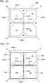
- the longitudinally extending section 65 of the planar light source 2a and the longitudinally extending section 66 of the planar light source 2b overlap with each other in the lateral direction X and form a band-like pattern section 120 continuous in a band shape as illustrated in Fig. 13 .
- the lateral shielding section 75 of the planar light source 2a and the lateral shielding section 75 of the planar light source 2b are linearly arranged in the lateral direction X and form a linear pattern section extending in a linear shape.
- the planar shielding section 81 of the planar light source 2a forms a circular pattern section 122 which is substantially circular together with the planar shielding section 80 of the planar light source 2b via the longitudinally extending sections 65, 66.
- the laterally extending section 67 of the planar light source 2a and the laterally extending section 68 of the planar light source 2b overlap with each other in the longitudinal direction Y and form a band-like pattern section 125 continuous in a band shape as illustrated in Fig. 13 .
- the longitudinal shielding section 76 of the planar light source 2a and the longitudinal shielding section 76 of the planar light source 2b are linearly arranged in the longitudinal direction Y and form a linear pattern section extending in a linear shape.
- the planar shielding section 85 of the planar light source 2a forms a circular pattern section 127 which is substantially circular together with the planar shielding section 86 of the planar light source 2b via the laterally extending sections 67, 68.
- the circular pattern sections 122, 127 are arranged at equal intervals in the longitudinal and lateral directions, and are distributed as lattice points as a whole.
- the light transmitting holes 98a to 98c of the planar light source 2a and the light transmitting holes 121 of the planar light source 2b have different total opening area. Therefore, the light transmitting holes 98a to 98c and the light transmitting holes 121 have different shielding rates, and have different light transmittance of light emitted from the light emitting region 30 of the planar light emitting panel 10. That is, since the shielding rate of the planar light source 2a is higher than that of the planar light source 2b, the planar light source 2a is darker than the planar light source 2b. Therefore, as illustrated in Fig.
- a difference in light intensity is generated between the planar light source 2a and the planar light source 2b. That is, in the illumination apparatus 1, one light gradation pattern is formed by a plurality of (in the present embodiment, nine) planar light sources 2 (2a, 2b) when viewed from a distance.
- the color of the cathode layer is reflected on the light emitting region 30 and thus the light emitting region 30 becomes a mirror surface, and the pattern forming section 60 of the decorative member 11 has a specular gloss. Therefore, the light emitting region 30 together with the pattern forming section 60 of the decorative member 11 constitutes one mirror surface when viewed from a distance.
- each of the planar light sources 2a, 2b forms a mirror surface, and the illumination apparatus 1 as a whole becomes one large mirror surface when viewed from a distance. Therefore, the living space 501 is displayed on the illumination apparatus 1, and the living space 501 can be made to look larger.
- the front surface of the planar light emitting panel 10 is covered with the pattern forming section 60, and the light-emission shielding section 62 is formed so as to partially shield light from the light emitting region 30. Therefore, the pattern of the pattern forming section 60 is emphasized by the light from the light emitting region 30 when the planar light sources are turned on, and the planar light sources 2a, 2b become excellent in design property.
- the light emitting region 30 of the planar light emitting panel 10 and the pattern forming section 60 of the decorative member 11 constitute one mirror surface when the planar light sources 2a, 2b are turned off. Therefore, the planar light sources 2a, 2b can function as a mirror.
- part or the whole of the light-emission shielding section 62 of the decorative member 11 is a crosspiece connecting the extending sections 65 to 68 of the frame shielding section 61, and the decorative member 11 functions as a reinforcing member of the planar light emitting panel 10. Therefore, mechanical strength of the planar light emitting panel 10 is reinforced and warping or the like of the planar light emitting panel 10 when the planar light sources 2a, 2b are turned on can be suppressed.
- the planar light sources 2a, 2b of the present embodiment since the light-emission shielding section 62 of the pattern forming section 60 covers the projection surface of the light emitting region 30 in the thickness direction, the light emitting region 30 is protected by the light-emission shielding section 62, and the light emitting part when the planar light sources 2a, 2b are turned on is not easily damaged.
- part of the elastic frame member 16 is sandwiched between the peripheral end surface of the planar light emitting tile 15 and the side-surface plate sections 52a to 52d of the decorative member 11. Therefore, it is possible to alleviate distortion due to a difference in thermal expansion coefficient between the planar light emitting tile 15 and the decorative member 11.
- the planar light sources 2a, 2b can emit light similarly.
- the pattern forming sections 60 of the respective planar light sources 2 are continuous and form one pattern, it is possible to display one pattern having large area when the illumination apparatus 1 is turned on.
- a large number of the triangular light transmitting holes 98a, 98b, 98c are provided in the pattern forming section 60 of each planar light source 2, and the light transmitting holes 98a, 98b, 98c are dispersed so as to form a planar shape as a whole. Therefore, a stained glass pattern can be displayed.
- the respective planar light sources 2 are continuous to constitute one mirror surface when the illumination apparatus 1 is turned off. Therefore, the illumination apparatus 1 can be used as a mirror having large area, and the illumination apparatus 1 can make the living space 501 look greater by displaying the living space 501.
- an illumination apparatus 200 according to a second embodiment of the present invention will be described. Note that identical reference numerals are given to configurations identical to those of the illumination apparatus 1 of the first embodiment, and the description thereof will be omitted.
- the illumination apparatus 200 of the second embodiment differs from the illumination apparatus 1 of the first embodiment in the shape of the mounting member. As illustrated in Fig. 16 , in the illumination apparatus 200, one planar light source 2 is supported by one mounting member 203. In addition, the mounting member 203 can fix the planar light source 2 in two postures.
- the mounting member 203 includes a main body wall section 210, side-surface wall sections 211a to 211d, projecting strip sections 101, 102, power supply sections 105a, 105b, and a fall prevention member 216.
- the main body wall section 210 is a section having a shape similar to that of a light emitting surface 12 of a planar light emitting panel 10 in front view.
- the main body wall section 210 is a square section.
- the side-surface wall sections 211a to 211d are wall sections erected from respective sides of the main body wall section 210.
- the side-surface wall sections 211b, 211d erected from longitudinal sides (sides extending in a longitudinal direction Y) of the main body wall section 210 have second mounting holes 217, 218, respectively.
- the second mounting holes 217, 218 are insertion holes into which fastening elements 505 are inserted in order to mount the mounting member 203 in a horizontal posture with respect to a mounting surface 500.
- the second mounting holes 217, 218 are through holes penetrating the side-surface wall sections 211b, 211d in a thickness direction of the side-surface wall sections 211b, 211d.
- the second mounting holes 217, 218 are arranged at an interval in the longitudinal direction Y in a vertical posture.
- the fall prevention member 216 is a member for preventing the planar light source 2 from falling from the mounting member 203.
- the fall prevention member 216 is a cord-like member and includes a mounting-side fixing section 225 fixed to the main body wall section 210, a panel-side fixing section 226 that can be fixed to the back surface of the planar light emitting panel 10, and a connecting section 227 connecting the mounting-side fixing section 225 and the panel-side fixing section 226.
- the mounting-side fixing section 225 which is one end section is supported in a cantilever manner by the main body wall section 210, and the panel-side fixing section 226 is a free end.
- the planar light source 2 is fixed in the vertical posture to the mounting surface 500 by the mounting member 203. That is, in the illumination apparatus 200, the light emitting surface 12 of the planar light source 2 is parallel to the mounting surface 500.
- the fastening element 505 such as a screw is inserted into the mounting hole 107, and the mounting member 203 is fixed to the mounting surface 500.
- Both end surfaces of the planar light source 2 in the lateral direction are covered with the side-surface wall sections 211a, 211c, and both end surfaces of the planar light source 2 in the longitudinal direction are covered with side-surface wall sections 211b, 211d. That is, the second mounting holes 217, 218 of the side-surface wall sections 211b, 211d are blocked by the end surfaces of the planar light source 2.
- the front surface of the planar light source 2 is flush with the side-surface wall sections 211a to 211d.
- the fall prevention member 216 is interposed between the main body wall section 210 of the mounting member 203 and the back surface of the planar light emitting panel 10.
- the panel-side fixing section 226 on the free-end side is fixed to the back surface of the planar light emitting panel 10.
- the planar light source 2 is fixed in the horizontal posture to the mounting surface 500 by the mounting member 203. That is, in the illumination apparatus 200, the light emitting surface 12 of the planar light source 2 spreads also in a direction perpendicular to the mounting surface 500.
- the fastening elements 505 such as screws are inserted into the second mounting holes 217, 217, and the mounting member 203 is fixed to the mounting surface 500.
- the both end surfaces of the planar light source 2 in the depth direction are covered with the side-surface wall sections 211b, 211d, and the both end surfaces of the planar light source 2 in the lateral direction are covered with the side-surface wall sections 211a, 211c. That is, the second mounting holes 217, 217 of the side-surface wall section 211b and head sections of the fastening elements 505 are blocked by the end surface of the planar light source 2.
- the illumination apparatus 200 of the second embodiment since the posture of the planar light source 2 with respect to the mounting surface 500 can be changed, there are few restrictions on the installation place.
- the fastening element 505 is hardly disengaged since the removal direction of the fastening element 505 is blocked by the end surface of the light emitting panel when the planar light source 2 is installed in the horizontal posture.
- the fall prevention member 216 is provided, it is possible to prevent the planar light source 2 from dropping onto the ground even if the planar light source 2 is detached from the mounting member 203.
- planar light source 250 according to a third embodiment will be described. Note that identical reference numerals are given to configurations identical to those of the illumination apparatuses 1, 200 of the first and second embodiments, and the description thereof will be omitted.
- the planar light source 250 of the third embodiment differs from the planar light source 2 of the first embodiment in the shape of the pattern forming section.
- a pattern forming section 252 of a decorative member 251 of the planar light source 250 includes a frame shielding section 61 and a light-emission shielding section 253.
- the light-emission shielding section 253 includes a lateral shielding section 255 horizontally crossing a light emitting region 30 of a planar light emitting panel 10, and a longitudinal shielding section 256 vertically crossing the light emitting region 30 of the planar light emitting panel 10 when viewed from the front.
- the lateral shielding section 255 includes connecting shielding sections 257, 258, and a central intersection 262.
- the connecting shielding section 257 connects a longitudinally extending section 65 and the central intersection 262, and the connecting shielding section 258 connects the central intersection 262 and a longitudinally extending section 66.
- the connecting shielding sections 257, 258 extend linearly in a lateral direction X.
- the longitudinal shielding section 256 includes connecting shielding sections 260, 261, and the central intersection 262.
- the connecting shielding section 260 connects a laterally extending section 67 and the central intersection 262, and the connecting shielding section 261 connects the central intersection 262 and a longitudinally extending section 67.
- the connecting shielding sections 260, 261 extend linearly in a longitudinal direction Y.
- the central intersection 262 is a section located at the center of the light-emission shielding section 253, and is a section where the lateral shielding section 255 and the longitudinal shielding section 256 intersect.
- the central intersection 262 is a section where the connecting shielding sections 257, 258, 260, 261 merge.
- the light-emission shielding section 253 is divided into four first regions 265a to 265d by the lateral shielding section 255 and the longitudinal shielding section 256.
- Each of the first regions 265a to 265d is a rectangular region, and specifically a square region.
- the first region 265a and the first region 265b are in line symmetry with the first region 265d and the first region 265c with the lateral shielding section 255 as the axis of symmetry.
- the first region 265a and the first region 265d are in line symmetry with the first region 265b and the first region 265c with the longitudinal shielding section 256 as the axis of symmetry.
- each of the first regions 265a to 265d second connecting shielding sections 266a to 266d are provided.
- Each of the first regions 265a to 265d is divided into four second regions 268a to 268d by the second connecting shielding sections 266a to 266d.
- the second connecting shielding sections 266a to 266d form an "X" shaped section in front view, and include shielding sections 270 to 273 and an intersection 275.
- the shielding section 270 is a section connecting the frame intersection 70 to 73 and the intersection 275
- the shielding section 271 is a section connecting the intersection 275 and the central intersection 262.
- the shielding sections 270, 271 linearly extend in an oblique direction and are linearly arranged. That is, each of the second connecting shielding sections 270, 271 has a lateral X component and a longitudinal Y component when viewed from the front.
- the shielding section 272 is a section connecting the middle section of the longitudinally extending section 65, 66 and the intersection 275
- the shielding section 273 is a section connecting the intersection 275 and the middle section of the laterally extending section 67, 68.
- the shielding sections 272, 273 linearly extend in an oblique direction and are linearly arranged in a direction crossing the shielding sections 270, 271. That is, each of the shielding sections 272, 273 has a lateral component and a longitudinal component when viewed from the front.
- intersection 275 is a section where the shielding sections 270 to 273 merge.
- Each of the second regions 268a to 268d is a right triangular region, and is 4-fold rotational symmetrical with the intersection 275 as the axis of symmetry.
- a third connecting shielding section 278 extending from a right-angled corner section toward a hypotenuse is provided in each of the second regions 268a to 268d.
- Each of the second regions 268a to 268d is divided into two third regions 280a, 280b by the third connecting shielding section 278.
- Each of the third regions 280a, 280b is a right triangular region, has a fourth connecting shielding section 281 and a fifth connecting shielding section 282 extending from a right-angled corner section toward a hypotenuse.
- the fourth connecting shielding section 281 is a section which extends so as to be a bisector of the right-angled corner section.
- the fifth connecting shielding section 282 is a section which extends so as to be a bisector of the corner section formed by the fourth connecting shielding section 281 and the third connecting shielding section 278.
- the third regions 280a, 280b are in line symmetrical with the third connecting shielding section 278 as the axis of symmetry.
- each of the third regions 280a, 280b is provided with a plurality of types of light transmitting holes 283a, 283b, 283c.
- the light transmitting holes 283a, 283b, 283c are holes through which light from the light emitting region 30 of the planar light emitting panel 10 can pass, and are through holes penetrating in a thickness direction of the main body plate section 51.
- Each of the light transmitting holes 283a, 283b, 283c has a triangular shape.
- the light transmitting holes 283a, 283b, 283c are holes provided in each of the third regions 280a, 280b, and are holes partitioned by the fourth connecting shielding section 281 and the fifth connecting shielding section 282.
- part of the light emitting region 30, laid bare through the decorative member 251 also becomes a mirror surface, and constitutes one mirror surface together with the pattern forming section 252 of the decorative member 251.
- the planar light source 250 of the third embodiment has a greater shielding rate of irradiation light from the light emitting region 30, which is shielded by the light-emission shielding section 253, than each of the shielding rates of the planar light sources 2a, 2b of the first embodiment. Therefore, the planar light source 250 can exhibit a darker color in a turn-on state in a case where the planar light source 250 is arranged side by side with the planar light sources 2a, 2b of the first embodiment.
- planar light source 300 according to a fourth embodiment will be described. Note that identical reference numerals are given to configurations identical to those of the planar light sources 2a, 2b, 250 of the first to third embodiments, and the description thereof will be omitted.
- the planar light source 300 of the fourth embodiment differs from the planar light source 250 of the third embodiment in the shape of part of the light-emission shielding section as illustrated in Fig. 24 .
- a light-emission shielding section 301 of the planar light source 300 is divided into four first regions 302a, 302b, 265c, 302d by a lateral shielding section 255 and a longitudinal shielding section 256.
- Each of the first regions 302a, 302b, 302d is a rectangular region, and specifically has a square shape.
- the first region 302a is in line symmetry with the first region 302d with the lateral shielding section 255 as the axis of symmetry, and is in line symmetry with the first region 302b with the longitudinal shielding section 256 as the axis of symmetry.
- the first region 302a (302b, 302d) is divided into five divided regions 307a to 307e by a second connecting shielding section 303 and second branch shielding sections 305, 306.
- the second connecting shielding section 303 is a section that crosses the first region 302a (302b, 302d) in an oblique direction and is a section that connects a frame intersection 70 (71 to 73) and a central intersection 262.
- the second connecting shielding section 303 is composed of a common shielding section 308 and branch shielding sections 310a, 310b.
- the common shielding section 308 is a section linearly extending from the frame intersection 70 toward the central intersection 262.
- the branch shielding sections 310a, 310b are sections which branch off from an end section of the common shielding section 308, extend in a curved manner, and merge at the central intersection 262.
- the second branch shielding section 305 is a section which connects to a longitudinally extending section 65(66) from a middle section of the branch shielding section 310a.
- the second branch shielding section 306 is a section which connects to a laterally extending section 68(67) from a middle section of the branch shielding section 310b.
- each of the first regions 302a, 302b, 302d is provided with five types of light transmitting holes 312a to 312e.
- the light transmitting holes 312a to 312e are holes through which light from a light emitting region 30 of a planar light emitting panel 10 can pass, and are through holes penetrating in a thickness direction of a main body plate section 51.
- the light transmitting holes 312a to 312e are holes provided in each of the first regions 302a, 302b, 302d, and are holes partitioned by the second connecting shielding section 303 and the second branch shielding sections 305, 306. That is, the light transmitting holes 312a to 312e are holes corresponding to the divided regions 307a to 307e, respectively.
- part of the light emitting region 30, which is not shielded by a decorative member also becomes a mirror surface, and constitutes one mirror surface together with a pattern forming section of the decorative member.
- planar light source 300 of the fourth embodiment since the first regions 302a, 302b, 265c, 302d having different shapes are provided, difference in light intensity can be generated within the planar light source 300 due to the difference in shielding rate.
- planar light source 350 according to a fifth embodiment will be described. Note that identical reference numerals are given to configurations identical to those of the planar light sources 2a, 2b, 250, 300 of the first to fourth embodiments, and the description thereof will be omitted.
- the planar light source 350 of the fifth embodiment differs from the planar light source 250 of the third embodiment in the shape of part of the light-emission shielding section as illustrated in Fig. 27 .
- a light-emission shielding section 351 of the planar light source 350 is divided into four first regions 77a, 355b, 355c, 77d by a lateral shielding section 352 and a longitudinal shielding section 353.
- Each of the first regions 355b, 355c is a rectangular region, and specifically has a square shape.
- the first region 355b and the first region 355b are in line symmetrical with the lateral shielding section 352 as the axis of symmetry.
- each of the first region 355b, 355c second connecting shielding sections 266a to 266d are provided.
- Each of the first regions 355b, 355c is divided into four second regions 356a to 356d by the second connecting shielding sections 266a to 266d.
- a third connecting shielding section 278 extending from a right-angled corner section toward a hypotenuse is provided in each of the second regions 356a to 356d.
- Each of the second regions 356a to 356d is divided into two third regions 357a, 357b by the third connecting shielding section 278.
- the third regions 357a, 357b differ from the third regions 280a, 280b of the third embodiment in that the third regions 357a, 357b do not include the fourth connecting shielding section 281 and the fifth connecting shielding section 282.
- the third regions 357a, 357b are provided with two types of light transmitting holes 358a, 358b.
- the light transmitting holes 358a, 358b are holes through which light from the light emitting region 30 of the planar light emitting panel 10 can pass, and are through holes penetrating in the thickness direction of the main body plate section 51.
- Each of the light transmitting holes 358a, 358b has a triangular shape.
- the light transmitting holes 358a, 358b are holes provided in the third regions 357a, 357b, and are holes partitioned by the third connecting shielding section 278.
- the first regions of different embodiments of the planar light source may be combined.
- one first region 77a of the first embodiment and three first regions 265a, 265b, 265d of the third embodiment may be combined (sixth embodiment).
- two first regions 77a, 77d of the first embodiment and two first regions 265b, 265c of the third embodiment may be combined (seventh embodiment).
- the light emitting region is divided by four or more shielding sections of the light-emission shielding section; however, the present invention is not limited to this.
- the light emitting region may be divided by three or less shielding sections.
- a light emitting region may be divided into two regions by one shielding section 400 (eighth embodiment).
- a light emitting region may be divided into four regions by two shielding sections 410, 411 crossing each other (ninth embodiment).
- a light emitting region may be divided into five regions by three shielding sections 420, 421, 422 (tenth embodiment).
- the light-emission shielding section divides the light emitting region 30 in each of the planar light sources 2.
- the present invention is not limited to this, and it is sufficient that a light-emission shielding section divides a light emitting region in at least one planar light source from among the planar light sources which constitute an illumination apparatus.
- a light-emission shielding section may not divide a light emitting region and may have a fan-shaped light transmitting hole as illustrated in Fig. 31 .
- the color of the cathode layer is reflected on the light emitting region 30 of the planar light emitting panel 10 and the light emitting region 30 constitutes a mirror surface when the planar light source is turned off; however, the present invention is not limited to this.
- the color of an anode layer may be reflected on a light emitting region of a planar light emitting panel and may constitute a mirror surface when the planar light source is turned off.
- the nine planar light sources 2 are mounted to the one mounting member; however, the present invention is not limited to this. Two or more and eight or less planar light sources 2 may be mounted to one mounting member, or ten or more planar light sources 2 may be mounted to one mounting member.
- planar light source having two types of pattern forming sections has been described; however, the present invention is not limited to this.
- An illumination apparatus may be formed of only planar light sources having one type of pattern forming sections.
- planar light sources having three or more types of pattern forming sections may mixedly exist.
- the planar light emitting panel is mounted to the mounting member by magnetic force between the reinforcing plate and the mounting member; however, the present invention is not limited to this.
- a decorative member may be formed of a ferromagnetic material, and a planar light emitting panel may be mounted to a mounting member by magnetic force between the decorative member and the mounting member.
- the reinforcing plate is formed of a ferromagnetic material and the magnetic force generating section is provided to the mounting member to generate magnetic force between the reinforcing plate and the mounting member.
- the present invention is not limited to this.
- Part of a mounting member may be formed of a ferromagnetic section and a magnetic force generating section may be provided on a reinforcing plate to generate magnetic force between the reinforcing plate and the mounting member.
- planar light emitting panel is mounted to the mounting member by magnetic force; however, the present invention is not limited to this.
- a planar light emitting panel may be mounted to a mounting member by using an engaging relationship, an adhesive means or the like.
- the region inside the frame shielding section is completely divided into a plurality of regions by the lateral shielding section 75, the longitudinal shielding section 76, and the like.
- the present invention is not limited to this.
- a light-emission shielding section 430 illustrated in Fig. 33 there may be a section part of which is not connected.
- the pattern forming section has the kakuasa pattern (pattern of a hemp leaf surrounded by a square); however, the present invention is not limited to this.
- the pattern forming section may have a Japanese traditional muntin pattern such as the asanoha (hemp leaf) pattern, the goma (sesame) pattern, the sakura (cherry blossom) pattern, the shokko pattern (lattice pattern with rectangles or octangles), the sayagatakuzushi pattern (deformed-swastika pattern), the izutsu waribishi pattern (pattern of combined diamonds), the waribishi tsunagi (pattern of repeated diamonds divided into four parts) the miebishi pattern (triple diamond pattern), the senbon goushi pattern (vertically long lattice pattern), the masu goshi pattern (pattern of square checks), the seigaiha pattern (wave pattern), the shippo pattern
- a Japanese traditional muntin pattern such as the asanoha (
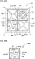
- the present invention includes in addition to the above-described embodiments, a planar light source as illustrated in Figs. 35A and 35B , a planar light source illustrated in Figs. 35C and 35D , a planar light source illustrated in Figs. 36A and 36B , and a planar light source illustrated in Figs. 36C and 36D , and the like.
Landscapes
- Engineering & Computer Science (AREA)
- General Engineering & Computer Science (AREA)
- Physics & Mathematics (AREA)
- Optics & Photonics (AREA)
- Architecture (AREA)
- Planar Illumination Modules (AREA)
- Non-Portable Lighting Devices Or Systems Thereof (AREA)
- Electroluminescent Light Sources (AREA)
- Fastening Of Light Sources Or Lamp Holders (AREA)
- Arrangement Of Elements, Cooling, Sealing, Or The Like Of Lighting Devices (AREA)
- Securing Globes, Refractors, Reflectors Or The Like (AREA)
Abstract

Description
- The present invention relates to a planar light source and an illumination apparatus that emit light in a planar shape.
- Conventionally, an organic EL panel has been used as a light source of an illumination apparatus (for example, Patent Document 1). Since the organic EL panel is a planar light source and has characteristics of being thin and lightweight, there are few restrictions on the installation place of the organic EL panel. Therefore, in recent years, application of the organic EL panel for a wall-surface illumination apparatus as well as for a ceiling illumination apparatus is considered. The wall-surface illumination apparatus is installed on a surface of a wall or the like. The ceiling illumination apparatus is installed on a ceiling.
- The wall-surface illumination apparatus used for a surface of a wall or the like not only functions as illumination but also is used as part of an interior decoration. Therefore, high design property is required.
- Patent Document 1:
JP 2016-152157 A - Incidentally, a conventional ceiling illumination apparatus used for a ceiling is installed such that light from a light emitting region of the organic EL panel is not shielded by another member in order to maximize light intensity of planar light. Therefore, the shape of the light emitting region is the irradiation range of the planar light as it is. For example, in the case of an organic EL panel in which the shape of the light source is rectangular, the shape of the light emitting region is also rectangular, and rectangular planar light is emitted. Therefore, if the conventional ceiling illumination apparatus is adopted as a wall-surface illumination apparatus as it is, illumination is uninteresting and gives monotonous impression when the apparatus is turned on, and further improvement of design property has been demanded.
- Therefore, an object of the present invention is to provide a planar light source and an illumination apparatus which have higher design property than that of conventional ones.
- One aspect of the present invention for solving the above problem is a planar light source including: a planar light emitting panel having a light emitting surface; and a decorative member covering the light emitting surface of the planar light emitting panel, wherein the light emitting surface includes: a light emitting region emitting light when the planar light source is turned on; and a non-light-emitting frame region surrounding the light emitting region, wherein the decorative member has a pattern forming section, and wherein the pattern forming section includes in a front view: a frame shielding section covering an entire area of the frame region; and a light-emission shielding section extending from the frame shielding section so as to divide the light emitting region into a plurality of regions.
- According to the present aspect, design property of the planar light emitting panel is higher than that of a conventional planar light emitting panel because light from the light emitting region is shielded by the pattern forming section of the decorative member, and light of a desired pattern is emitted.
- According to the present aspect, since the frame shielding section hides the non-light-emitting frame region of the planar light emitting panel in the front view, the non-light-emitting frame region of the planar light emitting panel is not visually recognized from a user side. Therefore, the non-light-emitting frame region does not affect the external shape of the planar light emitting panel, and a desired appearance can be formed by the pattern forming section.
- According to the present aspect, since the mechanical strength of the planar light emitting panel is reinforced by the frame shielding section surrounding the light emitting region of the decorative member and the light-emission shielding section dividing the light emitting region, warping or the like of the planar light emitting panel can be suppressed.
- In a preferred aspect, the light-emission shielding section covers from 5% to 75% both inclusive of the light emitting region in a front view.
- According to the present aspect, since the light-emission shielding section has a certain amount of area, it is possible to prevent trouble caused by a raise of panel temperature due to light-induced heat accumulated between the decorative member and the planar light emitting panel while sufficient mechanical strength is ensured.
- In a preferred aspect, the decorative member includes a main body plate section having the pattern forming section, and a side-surface plate section bent from an end section of the main body plate section, the planar light emitting panel includes: a planar light emitting tile; and a frame member protecting the planar light emitting tile, the frame member is made of resin and has elasticity, and part of the frame member is sandwiched by an end surface of the planar light emitting tile and the side-surface plate section.
- According to the present aspect, since part of the frame member having elasticity is sandwiched between the end surface of the planar light emitting tile and the side-surface plate section, the frame member can function as a buffer member and can absorb distortion due to thermal expansion of the planar light emitting tile. Therefore, even a planar light emitting tile having a thin glass panel as a supporting substrate is hard to break and has high safety.
- In a preferred aspect, the planar light emitting panel constitutes one mirror surface together with the pattern forming section when the planar light source is turned off.
- According to the present aspect, the planar light emitting panel can be used as one mirror when the planar light source is turned off.
- In a preferred aspect, the pattern forming section has at least two of the light-emission shielding sections having an identical width, the at least two of the light-emission shielding sections dividing the light emitting region into at least three regions in a front view.
- According to the present aspect, since the at least two light-emission shielding sections reinforce the light emitting region such that the light-emission shielding sections divide the light emitting region into three or more regions, the at least two light-emission shielding sections can function better as a crosspiece and warping or the like of the planar light emitting panel can be further protected.
- In a preferred aspect, the pattern forming section has a plate shape and includes a plurality of light transmitting holes that allow light from the light emitting region to pass through.
- According to the present aspect, since the pattern forming section includes the plurality of light transmitting holes through which light from the light emitting region can pass, it is possible to emit light having a shape matching the shapes of the light transmitting holes. That is, by forming the shapes of the light transmitting holes into a desired pattern, a desired pattern can be lit up.
- In a preferred aspect, the light-emission shielding section includes a shielding extending section extending with a longitudinal component and a lateral component in a front view.
- According to the present aspect, since the shielding extending section extends with the lateral component and the longitudinal component, the shielding extending section can reinforce the planar light emitting panel against warping, deflection, and the like in the longitudinal direction and the lateral direction.
- In a preferred aspect, some of the regions divided by the light-emission shielding sections have a different shielding rate, the shielding rate being defined as a ratio of an area where the pattern forming section is covering the light emitting region to an total area of the light emitting region.
- According to the present aspect, since regions having different shielding rates are contained in the regions obtained by dividing the light emitting region by the light-emission shielding section, a difference in light intensity is generated in the region of the planar light source when the planar light source is turned on, and it is easy to form a pattern when the planar light source is arranged side by side with another planar light source.
- One aspect of the present invention is an illumination apparatus including: a first of the planar light source; and a second of the planar light source. The second of the planar light source has the pattern forming section that is different from the pattern forming section of the first of the planar light source. The first of the planar light source and the second of the planar light source are arranged to be adjacent to each other. The first of the planar light source and the second of the planar light source have a different shielding rate, the shielding rate being defined as a ratio of an area where the pattern forming section is covering the light emitting region to an total area of the light emitting region.
- According to the present aspect, since the one planar light source and the other planar light source adjacent to each other have different shielding rates, a difference in light intensity of irradiation light is generated between the one planar light source and the other planar light source. Therefore, it is possible to form a pattern or a picture by using the difference in light intensity between the planar light sources, and to further improve design property.
- In a preferred aspect, the pattern forming section of the first of the planar light source and the pattern forming section of the second of the planar light source form one pattern when the first of the planar light source and the second of the planar light source are turned on.
- According to the present aspect, since one pattern can be formed by the difference in light intensity between the planar light sources, it is possible to further improve design property.
- One aspect of the present invention is an illumination apparatus including: the above-described planar light source; and a mounting member that can be fixed to a mounting surface. The mounting member has one of a magnetic force generating section and a ferromagnetic section, whereas the planar light source has the other of the magnetic force generating section and the ferromagnetic section on a back surface side, the magnetic force generating section and the ferromagnetic section forming a pair with each other. The planar light source is fixed to the mounting member by magnetic force generated between the magnetic force generating section and the ferromagnetic section.
- According to the present aspect, the planar light source is fixed to the mounting member by attractive force between the ferromagnetic section or the magnetic force generating section provided on the back surface of the planar light source and the magnetic force generating section or the ferromagnetic section of the mounting member. Therefore, the planar light source can be mounted to the mounting member without the light emitting surface being shielded by the ferromagnetic section and the magnetic force generating section.
- The planar light source and the illumination apparatus of the present invention have higher design property than that of a conventional planar light source and a conventional illumination apparatus.
-
-
Fig. 1 is a perspective view schematically illustrating a use state of an illumination apparatus according to a first embodiment of the present invention. -
Fig. 2 is an exploded perspective view of the illumination apparatus illustrated inFig. 1 . -
Fig. 3 is an exploded perspective view of a planar light source illustrated inFig. 2 . -
Fig. 4 is a perspective view of the planar light source illustrated inFig. 2 as viewed from another direction. -
Figs. 5A and 5B are cross-sectional views of the planar light source illustrated inFig. 2 , whereinFig. 5A is a longitudinal cross-sectional view, andFig. 5B is a transverse cross-sectional view. -
Figs. 6A and 6B are explanatory views of the planar light emitting panel illustratedFig. 3 , whereinFig. 6A is a front view, andFig. 6B is a back view. -
Fig. 7 is an exploded perspective view of the planar light emitting panel illustrated inFig. 3 . -
Fig. 8 is an exploded perspective view of the planar light emitting panel illustrated inFig. 7 seen from the back. -
Fig. 9 is a front view of a decorative member illustrated inFig. 3 . -
Figs. 10A to 10C are front views illustrating each region of the decorative member illustrated inFig. 9 , whereinFig. 10A illustrates entirety of the regions,Fig. 10B is a view which focuses on a first region, andFig. 10C is a view which focuses on a second region. -
Figs. 11A and 11B are explanatory views of a planar light source according to the first embodiment of the present invention, whereinFig. 11A is a front view of a planar light source different from the planar light source illustrated inFig. 2 , andFig. 11B is a front view illustrating each region. -
Fig. 12 is a perspective view of a mounting member illustrated inFig. 3 . -
Fig. 13 is a front view of main parts of the illumination apparatus illustrated inFig. 1 . -
Figs. 14A and 14B are plan views of the planar light source illustrated inFig. 2 , whereinFig. 14A illustrates a turn-on state, andFig. 14B illustrates a turn-off state. Note that a lighting part is indicated by dots. -
Figs. 15A and 15B are plan views of the illumination apparatus illustrated inFig. 1 , whereinFig. 15A illustrates a turn-on state, andFig. 15B illustrates a turn-off state. Note that a lighting part is indicated by dots. -
Fig. 16 is a perspective view in a case where an illumination apparatus according to a second embodiment of the present invention is installed on a mounting surface in a vertical posture. -
Fig.17 is an exploded perspective view of the illumination apparatus illustrated inFig. 16 . -
Fig. 18 is a perspective view when the illumination apparatus illustrated inFig. 16 is assembled in a case where the illumination apparatus is installed on the mounting surface in the vertical posture. -
Fig. 19 is a perspective view when the illumination apparatus illustrated inFig. 16 is assembled in a case where the illumination apparatus is installed on the mounting surface in a horizontal posture. -
Fig. 20 is a cross-sectional view of the illumination apparatus in the horizontal posture illustrated inFig. 19 . -
Fig. 21 is a front view of a decorative member according to a third embodiment of the present invention. -
Figs. 22A to 22C are front views illustrating each region of the decorative member illustrated inFig. 21 , whereinFig. 22A illustrates entirety of the regions,Fig. 22B is a view which focuses on a first region, andFig. 22C is a view which focuses on a second region. -
Figs. 23A and 23B are plan views of the planar light source according to the third embodiment of the present invention, whereinFig. 23A illustrates a turn-on state, andFig. 23B illustrates a turn-off state. Note that a lighting part is indicated by dots. -
Fig. 24 is a front view of a planar light source according to a fourth embodiment of the present invention. -
Figs. 25A and 25B are front views illustrating each region of the decorative member illustrated inFig. 24 , whereinFig. 25A illustrates entirety of the regions, andFig. 25B is a view which focuses on a first region. -
Figs. 26A and 26B are plan views of the planar light source according to the fourth embodiment of the present invention, whereinFig. 26A illustrates a turn-on state, andFig. 26B illustrates a turn-off state. Note that a lighting part is indicated by dots. -
Fig. 27 is a front view of a planar light source according to a fifth embodiment of the present invention. -
Figs. 28A to 28C are front views illustrating each region of the decorative member illustrated inFig. 27 , whereinFig. 28A illustrates entirety of the regions,Fig. 28B is a view which focuses on a first region, andFig. 28C is a view which focuses on a second region. -
Figs. 29A and 29B are front views of planar light sources according to other embodiments of the present invention, whereinFig. 29A illustrates a planar light source of a sixth embodiment, andFig. 29B illustrates a planar light source of a seventh embodiment. -
Figs. 30A to 30C are front views of planar light sources according to other embodiments of the present invention, whereinFig. 30A illustrates a planar light source of an eighth embodiment,Fig. 30B illustrates a planar light source of a ninth embodiment, andFig. 30C illustrates a planar light source of a tenth embodiment. -
Fig. 31 is a front view illustrating an example of a planar light source constituting an illumination apparatus according to another embodiment of the present invention. -
Fig. 32 is a front view illustrating an illumination apparatus according to another embodiment of the present invention. -
Fig. 33 is a front view of a planar light source according to another embodiment of the present invention. -
Figs. 34A to 34Q are front views of decorative members according to other embodiments of the present invention, whereinFig. 34A illustrates a case of the asanoha (hemp leaf) pattern,Fig. 34B illustrates a case of the goma (sesame) pattern,Fig. 34C illustrates a case of the sakura (cherry blossom) pattern,Fig. 34D illustrates a case of the shokko pattern (lattice pattern with rectangles or octangles),Fig. 34E illustrates a case of the sayagatakuzushi pattern (deformed-swastika pattern),Fig. 34F illustrates a case of the izutsu waribishi pattern (pattern of combined diamonds),Fig. 34G illustrates a case of the waribishi tsunagi pattern (pattern of repeated diamonds divided into four parts),Fig. 34H illustrates a case of the miebishi pattern (triple diamond pattern),Fig. 34I illustrates a case of the senbon goushi pattern (vertically long lattice pattern),Fig. 34J illustrates a case of the masu goshi pattern (pattern of square checks),Fig. 34K illustrates a case of the seigaiha pattern (wave pattern),Fig. 34L illustrates a case of the shippo pattern (pattern of overlapping circles divided into quarters),Fig. 34M illustrates a case of the kasane rindo pattern (pattern of overlapped autumn bellflowers),Fig. 34N illustrates a case of the kagome pattern (wickerwork pattern),Fig. 34O illustrates a case of the mitsukumite kikko pattern (pattern of diamonds divided into two equilateral triangles),Fig. 34P illustrates a case of the fundo watsunagi pattern (repeated counterweight pattern), andFig. 34Q illustrates a case of the tsumiishi kikko pattern (hexagonal pattern like piled rocks). -
Figs. 35A to 35D are front views of planar light sources according to other embodiments of the present invention, whereinFig. 35A illustrates a front view of a planar light source in a turn-off state according to another embodiment,Fig. 35B illustrates a front view of the planar light source illustrated inFig. 35A in a turn-on state,Fig. 35C illustrates a front view of a planar light source in a turn-off state according to an embodiment other than the embodiment illustrated inFig. 35A, and Fig. 35D illustrates a front view of the planar light source illustrated inFig. 35C in a turn-on state. Note that a lighting part is indicated by dots. -
Figs. 36A to 36D are front views of planar light sources according to other embodiments of the present invention, whereinFig. 36A illustrates a front view of a planar light source in a turn-off state according to another embodiment,Fig. 36B illustrates a front view of the planar light source illustrated inFig. 36A in a turn-on state,Fig. 36C illustrates a front view of a planar light source in a turn-off state according to an embodiment other than the embodiment illustrated inFig. 36A, and Fig. 36D illustrates a front view of the planar light source illustrated inFig. 36C in a turn-on state. Note that a lighting part is indicated by dots. - Hereinafter, embodiments of the present invention will be described in detail.
- As illustrated in
Fig. 1 , anillumination apparatus 1 according to a first embodiment of the present invention is mounted to a mountingsurface 500 which is a surface of a wall, a ceiling, a floor, or the like, and illuminates aliving space 501 side. Theillumination apparatus 1 is arranged side by side with otherplural illumination apparatuses 1 to constitute one illumination system. - As illustrated in
Fig. 2 , theillumination apparatus 1 includes one or more types of planarlight sources 2 and a mountingmember 3. - Here, in the following description, in order to facilitate understanding, a case will be described where the
illumination apparatus 1 is configured by combining two types of planar light sources 2 (2a, 2b) including pattern forming sections 60 (60a, 60b) having different shapes. - As illustrated in
Fig. 3 , the planarlight source 2a includes a planarlight emitting panel 10 and adecorative member 11. - The planar
light emitting panel 10 is a light emitting panel which spreads in a planar shape and can emit planar light. Specifically, the planarlight emitting panel 10 is an organic EL panel and can emit diffused light. As illustrated inFigs. 6A and 6B , the planarlight emitting panel 10 includes alight emitting surface 12 on one main surface side andpower supply sections - As illustrated in
Fig. 6A , on thelight emitting surface 12, there are alight emitting region 30 that actually emits light when the planar light source is turned on, and a non-light-emittingframe region 31 surrounding thelight emitting region 30. - The
light emitting region 30 is a region which actually emits and radiates light when the planar light source is turned on. - When viewed from the front, the
light emitting region 30 is an overlapping section of an anode layer built in the planarlight emitting panel 10, an organic functional layer including an organic light emitting layer, and a cathode layer. Thelight emitting region 30 is a section corresponding to an organic EL device in which an anode layer, an organic functional layer, and a cathode Layer are laminated in this order. That is, in a case where the planar light source is turned on, in thelight emitting region 30, a voltage is applied to the anode layer and the cathode layer, and therefore the organic light emitting layer emits and radiates light. - In addition, the color of the anode layer or the cathode layer is reflected on the
light emitting region 30 and thelight emitting region 30 becomes a mirror surface when the planar light source is turned off. - In the planar
light emitting panel 10 according to the present embodiment, a transparent conductive oxide layer which is a transparent conductive layer is adopted as the anode layer, and a metal layer or a metal alloy layer having metallic luster is adopted as the cathode layer. That is, the color of the cathode layer is reflected on thelight emitting region 30 according to the present embodiment and thelight emitting region 30 becomes a mirror surface when the planar light source is turned off. - The
light emitting region 30 has a rectangular shape when viewed from the front and is provided at the center of thelight emitting surface 12. In the present embodiment, thelight emitting region 30 is a square region. - A
frame region 31 is a continuous non-light-emitting region extending along the edge of the planarlight emitting panel 10 and surrounding thelight emitting region 30. That is, theframe region 31 is located outside thelight emitting region 30, and has a rectangular annular shape. - As illustrated in
Fig. 7 , the planarlight emitting panel 10 includes a planarlight emitting tile 15, aframe member 16, and a reinforcingplate 17. - The planar
light emitting tile 15 is a rectangular plate-shaped tile and is a thin plate-shaped tile. The planarlight emitting tile 15 of the present embodiment is an organic EL tile in which a thin glass substrate is used as a supporting substrate and the above-described organic EL device is laminated on the thin glass substrate. - As illustrated in
Fig. 8 , the planarlight emitting tile 15 includes thepower supply sections position adjusting sections - The
power supply sections light emitting tile 15. - The
position adjusting sections light emitting tile 15 with respect to the reinforcingplate 17, and also are sections for adjusting the position of the planarlight source 2a with respect to the mountingmember 3. Specifically, theposition adjusting sections light emitting tile 15. - The
frame member 16 is a protective frame for protecting the end surfaces of the planarlight emitting tile 15, and is an elastic member made of resin. Theframe member 16 is a frame having a rectangular annular shape when viewed from the front. As illustrated inFigs. 7 and8 , theframe member 16 includes light-emitting-side covering sections 20a to 20d, end-surface-side covering sections 21a to 21d, and a back-surface-side covering section 22. - The light-emitting-
side covering sections 20a to 20d are sections covering alight emitting surface 12 side of the planarlight emitting tile 15, and are sections belonging to theframe region 31 of the planarlight emitting panel 10. - The end-surface-
side covering sections 21a to 21d are connecting wall sections that connect the end sections of the light-emitting-side covering sections 20a to 20d and the end section of the back-surface-side covering section 22, and are sections covering the end surfaces of the planarlight emitting tile 15. - As illustrated in
Fig. 8 , the back-surface-side covering section 22 is a section that covers the back surface side of the planarlight emitting tile 15. The back-surface-side covering section 22 includes a plurality ofside projecting sections 25a to 25y and fourcorner engaging sections 26a to 26d. - The
side projecting sections 25a to 25y are sections bent from the end-surface-side covering sections 21a to 21d. - The
side projecting sections 25a to 25y are projecting pieces that project from the end-surface-side covering sections 21a to 21d toward the center when viewed from the back, and are fitting sections which can be fitted to side recessedsections 41a to 41y of the reinforcingplate 17. - The
side projecting sections 25a to 25y are arranged at intervals along each side of the planarlight emitting panel 10. In the present embodiment, the side projecting sections 25, 25 belonging to an identical side are arranged at equal intervals. - The
corner engaging sections 26a to 26d are engaging sections that are provided at the corner sections of the back-surface-side covering section 22 and can engage withcorner engaging sections 42a to 42d of the reinforcingplate 17, respectively. Each of thecorner engaging sections 26a to 26d has a right triangle shape. - The reinforcing
plate 17 is a plate-shaped section covering the back surface side of the planarlight emitting panel 10, and is a ferromagnetic section made of a ferromagnetic material. Specifically, the reinforcingplate 17 is an iron plate which is a ferromagnetic material. - As illustrated in
Fig. 8 , the reinforcingplate 17 includes amain body section 40, the side recessedsections 41a to 41y, and thecorner engaging sections 42a to 42d. - The
main body section 40 is a rectangular section in front view, and includesposition adjusting holes supply insertion holes - The
position adjusting holes position adjusting sections plate 17 with respect to the planarlight emitting tile 15. Specifically, theposition adjusting holes position adjusting sections main body section 40 in the thickness direction of themain body section 40. - The power-
supply insertion holes power supply sections light emitting tiles 15 can be inserted, and are through holes penetrating themain body section 40 in the thickness direction. - As can be seen from
Fig. 8 , the side recessedsections 41a to 41y are cutout sections extending inward from the edge of themain body section 40 when viewed from the back, and are fitting sections which can be fitted to theside projecting sections 25a to 25y of theframe member 16. - The side recessed
sections 41a to 41y are arranged at intervals along each side of the planarlight emitting panel 10. In the present embodiment, the side recessed sections 41, 41 belonging to an identical side are arranged at equal intervals. - The
corner engaging sections 42a to 42d are engaging sections that are provided at the corner sections of themain body section 40 and can engage with thecorner engaging sections 26a to 26d of theframe member 16, respectively. Each of thecorner engaging sections 42a to 42d has a right triangle shape. - The
decorative member 11 is a member having specular gloss when viewed from the front. In thedecorative member 11 of the present embodiment, at least the front surface is formed of a metal or a metal alloy and has a metallic luster. - As can be seen from
Fig. 3 , thedecorative member 11 includes a mainbody plate section 51, and side-surface plate sections 52a to 52d bent from the end section of the mainbody plate section 51. - The main
body plate section 51 is a decorative plate for covering thelight emitting surface 12 side of the planarlight emitting panel 10. As illustrated inFig. 9 , the mainbody plate section 51 includes apattern forming section 60a forming a specific pattern. - As illustrated in
Fig. 9 , thepattern forming section 60a is a section which is a muntin and has the kakuasa pattern (pattern of a hemp leaf surrounded by a square) in front view. Thepattern forming section 60a includes aframe shielding section 61 covering theframe region 31, and a light-emission shielding section 62 covering part of thelight emitting region 30. - The
frame shielding section 61 is a section overlapping with the entire area of theframe region 31 when viewed from the front, and is a section shielding light from the planarlight emitting panel 10 side. That is, theframe shielding section 61 is composed of longitudinally extendingsections sections longitudinally extending sections sections - In other words, the
frame shielding section 61 includesframe intersections 70 to 73 where thelongitudinally extending sections sections - The
frame intersections 70 to 73 are corner intersections constituting corner sections of thepattern forming section 60a, and are formed at four corners, respectively. - The light-
emission shielding section 62 includes alateral shielding section 75 horizontally crossing thelight emitting region 30 of the planarlight emitting panel 10, and alongitudinal shielding section 76 vertically crossing thelight emitting region 30 of the planarlight emitting panel 10 when viewed from the front. - As illustrated in
Fig. 9 , thelateral shielding section 75 includesplanar shielding sections sections central intersection 89. - The
planar shielding sections longitudinally extending sections longitudinally extending sections central intersection 89. That is, each of theplanar shielding sections planar shielding sections longitudinally extending sections - The "middle section" here means an intermediate section in the extending direction and refers to a section other than an end section. The same shall apply hereinafter.
- The connecting
shielding section 82 is a section connecting theplanar shielding section 80 and thecentral intersection 89, and the connectingshielding section 83 is a section connecting thecentral intersection 89 and theplanar shielding section 80. The connectingshielding sections - As illustrated in
Fig. 9 , thelongitudinal shielding section 76 includesplanar shielding sections sections central intersection 89. - The
planar shielding sections sections sections central intersection 89. Theplanar shielding sections sections - The connecting
shielding section 87 is a section connecting theplanar shielding section 85 and thecentral intersection 89, and the connectingshielding section 88 is a section connecting thecentral intersection 89 and theplanar shielding section 86. The connectingshielding sections - The
central intersection 89 is a section located at the center of the light-emission shielding section 62 and is a section where thelateral shielding section 75 and thelongitudinal shielding section 76 intersect. That is, thecentral intersection 89 is a section where the connectingshielding sections - As illustrated in
Fig. 10A , the light-emission shielding section 62 is divided into fourfirst regions 77a to 77d by thelateral shielding section 75 and thelongitudinal shielding section 76. - Each of the
first regions 77a to 77d is a rectangular region, and specifically has a square shape. - The
first regions first regions lateral shielding section 75 as the axis of symmetry, and thefirst regions first regions longitudinal shielding section 76 as the axis of symmetry. That is, the light-emission shielding section 62 is 4-fold rotational symmetrical with thecentral intersection 89 as the rotation axis when viewed from the front. - As can be seen from
Fig. 10B , in thefirst regions 77a (77b to 77d), second connecting shieldingsections 90a to 90d (shielding extending sections) are provided, and thefirst regions 77a to 77d are divided into twosecond regions sections 90a (90b to 90d), respectively. - The second connecting shielding
sections 90a to 90d are sections connecting theplanar shielding sections planar shielding sections sections 90a to 90d has a lateral X component and a longitudinal Y component when viewed from the front. - Both of the
second regions section 90a (90b to 90d) as the axis of symmetry. - As illustrated in
Fig. 10C , third connectingshielding sections 95a to 95c (shielding extending sections) extending from respective apexes toward the center are provided in each of thesecond regions shielding sections 95a to 95c intersect at oneintersection 96. - Each of the
second regions third regions shielding sections 95a to 95c which each extend so as to be a bisector of each corner. - Each of the
third regions - The
third regions light transmitting holes - The
light transmitting holes light emitting region 30 of the planarlight emitting panel 10 can pass, and are through holes penetrating in the thickness direction of the mainbody plate section 51. Each of thelight transmitting holes - Here, the positional relationship of each section of the planar
light source 2 of the present embodiment will be described. - As illustrated in
Figs. 5A and 5B , in the planarlight emitting panel 10, the reinforcingplate 17 covers the back surface of the planarlight emitting tile 15, and part of thepower supply sections supply insertion holes - Part of the front surface side of the planar
light emitting tile 15 is covered with the light-emitting-side covering sections 20a to 20d of theframe member 16. The end surfaces of the planarlight emitting tile 15 are covered with the end-surface-side covering sections 21a to 21d of theframe member 16. - Part of the back surface side of the planar
light emitting tile 15 is covered with the back-surface-side covering section 22 of theframe member 16, and the remaining part is covered with the reinforcingplate 17. - As can be seen from
Figs. 4 and8 , in theframe member 16, theside projecting sections 25a to 25y are inserted and fitted into the side recessedsections 41a to 41y of the reinforcingplate 17, and thecorner engaging sections 26a to 26d are engaged with thecorner engaging sections 42a to 42d of the reinforcingplate 17. - In the
decorative member 11, as illustrated inFig. 3 , thepattern forming section 60a of the mainbody plate section 51 covers the front surface side of the planarlight emitting panel 10. Specifically, as can be seen fromFigs. 5A and 5B , in thepattern forming section 60a, the extendingsections 65 to 68 of theframe shielding section 61 cover the light-emitting-side covering sections 20a to 20d of theframe member 16, and the light-emission shielding section 62 covers the light emitting section of the planarlight emitting tile 15 when the planar light source is turned on. In other words, in thepattern forming section 60a, theframe shielding section 61 covers theframe region 31 of the planarlight emitting panel 10, and the light-emission shielding section 62 covers thelight emitting region 30 of the planarlight emitting panel 10. - In the
decorative member 11, as can be seen fromFigs. 5A and 5B , the side-surface plate section 52 covers the end surface of the planarlight emitting panel 10. That is, the end-surface-side covering sections 21a to 21d of theframe member 16 are interposed between the side-surface plate sections 52a to 52d of thedecorative member 11 and the end surface of the planarlight emitting tile 15. In other words, the end-surface-side covering sections 21a to 21d of theframe member 16 are sandwiched between the side-surface plate sections 52a to 52d of thedecorative member 11 and the end surfaces of the planarlight emitting tile 15, respectively. - Subsequently, the planar
light source 2b will be described. Since the planarlight source 2b is identical to the planarlight source 2a except for the shape of the pattern forming section 60, overlapping description will be omitted. In apattern forming section 60b, identical reference signs are given to configurations identical to those of thepattern forming section 60a, and the description thereof will be omitted. - As illustrated in
Fig. 11A , thepattern forming section 60b of the planarlight source 2b includes aframe shielding section 61 covering aframe region 31 and a light-emission shielding section 119 covering part of thelight emitting region 30. - The light-
emission shielding section 119 of thepattern forming section 60b includes alateral shielding section 75 horizontally crossing thelight emitting region 30 of a planarlight emitting panel 10, and alongitudinal shielding section 76 vertically crossing thelight emitting region 30 of the planarlight emitting panel 10. As illustrated inFig. 11B , the light-emission shielding section 62 is divided into fourfirst regions 130a to 130d by thelateral shielding section 75 and thelongitudinal shielding section 76. - Unlike the
first regions 77a to 77d, thefirst regions 130a to 130d are not provided with second connecting shieldingsections 90a to 90d or the like. That is, unlike the light-emission shielding section 62 of thepattern forming section 60a, only thelateral shielding section 75 and thelongitudinal shielding section 76 are provided in the light-emission shielding section 119 of thepattern forming section 60b. - In addition, four rectangular
light transmitting holes 121 are provided in thefirst regions 130a to 130d. - Here, as described above, there are the two kinds of pattern forming sections 60 (60a, 60b) in the planar
light sources 2 constituting theillumination apparatus 1. - The shielding rate of each of the light-
emission shielding sections pattern forming sections emission shielding sections pattern forming sections light emitting region 30 of the planarlight emitting panel 10 when viewed from the front. - Within the above range, the light-
emission shielding section 62 has a certain amount of area. Therefore, it is possible to prevent trouble caused by an increase in temperature of the planarlight emitting panel 10 due to light-induced heat accumulated between thedecorative member 11 and the planarlight emitting panel 10 while sufficient mechanical strength is ensured. - Note that the term "shielding rate" as used herein refers to the light shielding rate against the total area of the light emitting region. That is, the shielding rate of the pattern forming section 60 represents the rate of area where the pattern forming section 60 covers the
light emitting region 30 of the planarlight emitting panel 10 against the total area of thelight emitting region 30 of the planarlight emitting panel 10 when viewed from the front. - In addition, the shielding rate of the light-
emission shielding section 119 of thepattern forming section 60b is smaller than the shielding rate of the light-emission shielding section 62 of thepattern forming section 60a. - The difference between the shielding rate of the light-
emission shielding section 62 of thepattern forming section 60a and the shielding rate of the light-emission shielding section 119 of thepattern forming section 60b is preferably 10% to 70% inclusive, and more preferably 20% to 60% inclusive from a viewpoint of increasing the difference in light intensity in theillumination apparatus 1. - The mounting
member 3 is a member that can be fixed to the mountingsurface 500 such as a wall and is a member that mounts the plurality of planarlight sources 2a to the mountingsurface 500. - As illustrated in
Fig. 12 , the mountingmember 3 includes a plurality of fixingunits 110a to 110c. The fixingunits 110a to 110c are belt-shaped sections extending in the lateral direction X and aligned in the longitudinal direction Y. Each of the fixingunits 110a to 110c include a mainbody wall section 100, projectingstrip sections power supply sections - The main
body wall section 100 is a rectangular wall section in front view, and is a long plate-like section extending in the lateral direction X. - The projecting
strip sections body wall section 100 toward the front side, and extend in the lateral direction X. Each of the projectingstrip sections - The magnetic force generating section generates magnetic force and attracts the reinforcing
plate 17 of the planarlight source 2. - The magnetic force generating section is composed of a permanent magnet.
- The projecting
strip sections groove 106 together with the mainbody wall section 100. - The recessed
groove 106 is a section that is sandwiched by the projectingstrip sections strip sections - The recessed
groove 106 is a bottomed groove into which theposition adjusting sections light source 2a can be inserted, and is a section that regulates the moving direction and the posture of theposition adjusting sections - As illustrated in
Fig. 12 , the recessedgroove 106 has a mountinghole 107 at a bottom section. - The mounting
hole 107 is a hole into which afastening element 505 is inserted in order to mount the mountingmember 3 to the mountingsurface 500. The mountinghole 107 is a through hole penetrating the mainbody wall section 100 constituting the bottom section of the recessedgroove 106 in the thickness direction and is an elongated hole extending in the lateral direction X. - The term "fastening element" as used herein is a generic concept of a screw, a nail, a rivet, and the like, and is a concept including a temporary fastening element. The same shall apply hereinafter.
- The
fastening element 505 of the present embodiment is a temporary fastening element, specifically, a screw having a head section and a shaft section. - The
power supply sections power supply sections light source 2a. Thepower supply sections light source 2a by contacting thepower supply sections light source 2a. - Subsequently, the positional relationship of each constituent of the
illumination apparatus 1 of the present embodiment will be described. - As illustrated in
Fig. 13 , theillumination apparatus 1 includes the plurality of types of planarlight sources member 3. In theillumination apparatus 1, the planarlight source 2a and the planarlight source 2b are alternately arranged vertically and horizontally by the mountingmember 3. - Specifically, in the
illumination apparatus 1, the reinforcingplate 17 of each planarlight source 2 is attracted by the magnetic force generating section of the mountingmember 3, and the planarlight sources 2 are fixed to the fixingunits 110a to 110c of respective stages. That is, in theillumination apparatus 1, the planarlight source 2a, the planarlight source 2b, and the planarlight source 2a are arranged side by side in the lateral direction X in this order by the fixingunit 110a on a first stage, the planarlight source 2b, the planarlight source 2a, and the planarlight source 2b are arranged side by side in the lateral direction X in this order by the fixingunit 110b on a second stage, and the planarlight source 2a, the planarlight source 2b, and the planarlight source 2a are arranged side by side in the lateral direction X in this order by the fixingunit 110c on a third stage. - The
fastening element 505 such as a screw is inserted into the mountinghole 107 and the mountingmember 3 is fixed to the mountingsurface 500. In the recessedgroove 106 of the mountingmember 3, theposition adjusting holes plate 17 constituting part of the back surface of the planarlight emitting panel 10 are inserted. The power supply section 105 passes through the power-supply insertion hole 45 and is connected to the power supply section 13 of the planarlight emitting tile 15. - When the planar
light source 2a and the planarlight source 2b adjacent in the lateral direction X are focused on, thelongitudinally extending section 65 of the planarlight source 2a and thelongitudinally extending section 66 of the planarlight source 2b overlap with each other in the lateral direction X and form a band-like pattern section 120 continuous in a band shape as illustrated inFig. 13 . Thelateral shielding section 75 of the planarlight source 2a and thelateral shielding section 75 of the planarlight source 2b are linearly arranged in the lateral direction X and form a linear pattern section extending in a linear shape. Theplanar shielding section 81 of the planarlight source 2a forms acircular pattern section 122 which is substantially circular together with theplanar shielding section 80 of the planarlight source 2b via thelongitudinally extending sections - When the planar
light source 2a and the planarlight source 2b adjacent in the longitudinal direction Y are focused on, the laterally extendingsection 67 of the planarlight source 2a and the laterally extendingsection 68 of the planarlight source 2b overlap with each other in the longitudinal direction Y and form a band-like pattern section 125 continuous in a band shape as illustrated inFig. 13 . Thelongitudinal shielding section 76 of the planarlight source 2a and thelongitudinal shielding section 76 of the planarlight source 2b are linearly arranged in the longitudinal direction Y and form a linear pattern section extending in a linear shape. Theplanar shielding section 85 of the planarlight source 2a forms acircular pattern section 127 which is substantially circular together with theplanar shielding section 86 of the planarlight source 2b via the laterally extendingsections circular pattern sections - Subsequently, a turned-on state and a turned-off state of the
illumination apparatus 1 of the present embodiment will be described. - First, the state in which the
illumination apparatus 1 is turned on will be described. - As illustrated in
Fig. 14A , in the planarlight sources light emitting region 30 is shielded by the pattern forming section 60, and a pattern along the shape of the pattern forming section 60 is reflected. That is, light from thelight emitting region 30 passes through the respectivelight transmitting holes 98a to 98c and radiates into theliving space 501 side, and only the sections where thelight transmitting holes 98a to 98c are formed emit light. - In addition, in the
entire illumination apparatus 1, as described above, thelight transmitting holes 98a to 98c of the planarlight source 2a and thelight transmitting holes 121 of the planarlight source 2b have different total opening area. Therefore, thelight transmitting holes 98a to 98c and thelight transmitting holes 121 have different shielding rates, and have different light transmittance of light emitted from thelight emitting region 30 of the planarlight emitting panel 10. That is, since the shielding rate of the planarlight source 2a is higher than that of the planarlight source 2b, the planarlight source 2a is darker than the planarlight source 2b. Therefore, as illustrated inFig. 15A , a difference in light intensity is generated between the planarlight source 2a and the planarlight source 2b. That is, in theillumination apparatus 1, one light gradation pattern is formed by a plurality of (in the present embodiment, nine) planar light sources 2 (2a, 2b) when viewed from a distance. - Subsequently, a state in which the
illumination apparatus 1 is turned off will be described. - As illustrated in
Fig. 14B , in the planarlight emitting panel 10, the color of the cathode layer is reflected on thelight emitting region 30 and thus thelight emitting region 30 becomes a mirror surface, and the pattern forming section 60 of thedecorative member 11 has a specular gloss. Therefore, thelight emitting region 30 together with the pattern forming section 60 of thedecorative member 11 constitutes one mirror surface when viewed from a distance. - In addition, as illustrated in
Fig. 15B , in theillumination apparatus 1, each of the planarlight sources illumination apparatus 1 as a whole becomes one large mirror surface when viewed from a distance. Therefore, the livingspace 501 is displayed on theillumination apparatus 1, and theliving space 501 can be made to look larger. - According to the planar
light sources light emitting panel 10 is covered with the pattern forming section 60, and the light-emission shielding section 62 is formed so as to partially shield light from thelight emitting region 30. Therefore, the pattern of the pattern forming section 60 is emphasized by the light from thelight emitting region 30 when the planar light sources are turned on, and the planarlight sources - According to the planar
light sources light emitting region 30 of the planarlight emitting panel 10 and the pattern forming section 60 of thedecorative member 11 constitute one mirror surface when the planarlight sources light sources - According to the planar
light sources emission shielding section 62 of thedecorative member 11 is a crosspiece connecting the extendingsections 65 to 68 of theframe shielding section 61, and thedecorative member 11 functions as a reinforcing member of the planarlight emitting panel 10. Therefore, mechanical strength of the planarlight emitting panel 10 is reinforced and warping or the like of the planarlight emitting panel 10 when the planarlight sources - According to the planar
light sources emission shielding section 62 of the pattern forming section 60 covers the projection surface of thelight emitting region 30 in the thickness direction, thelight emitting region 30 is protected by the light-emission shielding section 62, and the light emitting part when the planarlight sources - According to the planar
light sources elastic frame member 16 is sandwiched between the peripheral end surface of the planarlight emitting tile 15 and the side-surface plate sections 52a to 52d of thedecorative member 11. Therefore, it is possible to alleviate distortion due to a difference in thermal expansion coefficient between the planarlight emitting tile 15 and thedecorative member 11. - According to the
illumination apparatus 1 of the present embodiment, since thefirst regions 77a to 77d and thefirst regions 130a to 130d of the planarlight sources light sources member 3 in any direction, the planarlight sources - According to the
illumination apparatus 1 of the present embodiment, since the pattern forming sections 60 of the respective planarlight sources 2 are continuous and form one pattern, it is possible to display one pattern having large area when theillumination apparatus 1 is turned on. - In addition, according to the
illumination apparatus 1 of the present embodiment, a large number of the triangularlight transmitting holes light source 2, and thelight transmitting holes - According to the
illumination apparatus 1 of the present embodiment, the respective planarlight sources 2 are continuous to constitute one mirror surface when theillumination apparatus 1 is turned off. Therefore, theillumination apparatus 1 can be used as a mirror having large area, and theillumination apparatus 1 can make theliving space 501 look greater by displaying theliving space 501. - Subsequently, an
illumination apparatus 200 according to a second embodiment of the present invention will be described. Note that identical reference numerals are given to configurations identical to those of theillumination apparatus 1 of the first embodiment, and the description thereof will be omitted. - The
illumination apparatus 200 of the second embodiment differs from theillumination apparatus 1 of the first embodiment in the shape of the mounting member. As illustrated inFig. 16 , in theillumination apparatus 200, one planarlight source 2 is supported by one mountingmember 203. In addition, the mountingmember 203 can fix the planarlight source 2 in two postures. - As illustrated in
Fig. 17 , the mountingmember 203 includes a mainbody wall section 210, side-surface wall sections 211a to 211d, projectingstrip sections power supply sections fall prevention member 216. - The main
body wall section 210 is a section having a shape similar to that of alight emitting surface 12 of a planarlight emitting panel 10 in front view. In the present embodiment, the mainbody wall section 210 is a square section. - The side-
surface wall sections 211a to 211d are wall sections erected from respective sides of the mainbody wall section 210. - The side-
surface wall sections body wall section 210 have second mountingholes - The second mounting holes 217, 218 are insertion holes into which
fastening elements 505 are inserted in order to mount the mountingmember 203 in a horizontal posture with respect to a mountingsurface 500. The second mounting holes 217, 218 are through holes penetrating the side-surface wall sections surface wall sections - The second mounting holes 217, 218 are arranged at an interval in the longitudinal direction Y in a vertical posture.
- The
fall prevention member 216 is a member for preventing the planarlight source 2 from falling from the mountingmember 203. - As illustrated in
Fig. 17 , thefall prevention member 216 is a cord-like member and includes a mounting-side fixing section 225 fixed to the mainbody wall section 210, a panel-side fixing section 226 that can be fixed to the back surface of the planarlight emitting panel 10, and a connectingsection 227 connecting the mounting-side fixing section 225 and the panel-side fixing section 226. - In the
fall prevention member 216, the mounting-side fixing section 225 which is one end section is supported in a cantilever manner by the mainbody wall section 210, and the panel-side fixing section 226 is a free end. - Subsequently, the positional relationship of each member when the
illumination apparatus 200 is attached to the mountingsurface 500 will be described. - First, a case where the
illumination apparatus 200 is mounted to the mountingsurface 500 in the vertical posture will be described. - As can be seen from
Fig. 18 , in theillumination apparatus 200, the planarlight source 2 is fixed in the vertical posture to the mountingsurface 500 by the mountingmember 203. That is, in theillumination apparatus 200, thelight emitting surface 12 of the planarlight source 2 is parallel to the mountingsurface 500. - Specifically, the
fastening element 505 such as a screw is inserted into the mountinghole 107, and the mountingmember 203 is fixed to the mountingsurface 500. - Both end surfaces of the planar
light source 2 in the lateral direction are covered with the side-surface wall sections light source 2 in the longitudinal direction are covered with side-surface wall sections holes surface wall sections light source 2. - The front surface of the planar
light source 2 is flush with the side-surface wall sections 211a to 211d. - The
fall prevention member 216 is interposed between the mainbody wall section 210 of the mountingmember 203 and the back surface of the planarlight emitting panel 10. The panel-side fixing section 226 on the free-end side is fixed to the back surface of the planarlight emitting panel 10. - Subsequently, a case where the
illumination apparatus 200 is mounted to the mountingsurface 500 in the horizontal posture will be described. - As can be seen from
Fig. 19 , in theillumination apparatus 200, the planarlight source 2 is fixed in the horizontal posture to the mountingsurface 500 by the mountingmember 203. That is, in theillumination apparatus 200, thelight emitting surface 12 of the planarlight source 2 spreads also in a direction perpendicular to the mountingsurface 500. - Specifically, the
fastening elements 505 such as screws are inserted into the second mountingholes member 203 is fixed to the mountingsurface 500. As illustrated inFig. 20 , the both end surfaces of the planarlight source 2 in the depth direction are covered with the side-surface wall sections light source 2 in the lateral direction are covered with the side-surface wall sections holes surface wall section 211b and head sections of thefastening elements 505 are blocked by the end surface of the planarlight source 2. - According to the
illumination apparatus 200 of the second embodiment, since the posture of the planarlight source 2 with respect to the mountingsurface 500 can be changed, there are few restrictions on the installation place. - According to the
illumination apparatus 200 of the second embodiment, thefastening element 505 is hardly disengaged since the removal direction of thefastening element 505 is blocked by the end surface of the light emitting panel when the planarlight source 2 is installed in the horizontal posture. - According to the
illumination apparatus 200 of the second embodiment, since thefall prevention member 216 is provided, it is possible to prevent the planarlight source 2 from dropping onto the ground even if the planarlight source 2 is detached from the mountingmember 203. - Subsequently, a planar
light source 250 according to a third embodiment will be described. Note that identical reference numerals are given to configurations identical to those of theillumination apparatuses - The planar
light source 250 of the third embodiment differs from the planarlight source 2 of the first embodiment in the shape of the pattern forming section. - As illustrated in
Fig. 21 , apattern forming section 252 of adecorative member 251 of the planarlight source 250 includes aframe shielding section 61 and a light-emission shielding section 253. - The light-
emission shielding section 253 includes alateral shielding section 255 horizontally crossing alight emitting region 30 of a planarlight emitting panel 10, and alongitudinal shielding section 256 vertically crossing thelight emitting region 30 of the planarlight emitting panel 10 when viewed from the front. - As illustrated in
Fig. 21 , thelateral shielding section 255 includes connecting shieldingsections central intersection 262. - The connecting
shielding section 257 connects alongitudinally extending section 65 and thecentral intersection 262, and the connectingshielding section 258 connects thecentral intersection 262 and alongitudinally extending section 66. The connectingshielding sections - As illustrated in
Fig. 21 , thelongitudinal shielding section 256 includes connecting shieldingsections central intersection 262. - The connecting
shielding section 260 connects a laterally extendingsection 67 and thecentral intersection 262, and the connectingshielding section 261 connects thecentral intersection 262 and alongitudinally extending section 67. The connectingshielding sections - The
central intersection 262 is a section located at the center of the light-emission shielding section 253, and is a section where thelateral shielding section 255 and thelongitudinal shielding section 256 intersect. Thecentral intersection 262 is a section where the connecting shieldingsections - As illustrated in
Fig. 22A , the light-emission shielding section 253 is divided into fourfirst regions 265a to 265d by thelateral shielding section 255 and thelongitudinal shielding section 256. - Each of the
first regions 265a to 265d is a rectangular region, and specifically a square region. - The
first region 265a and thefirst region 265b are in line symmetry with thefirst region 265d and thefirst region 265c with thelateral shielding section 255 as the axis of symmetry. Thefirst region 265a and thefirst region 265d are in line symmetry with thefirst region 265b and thefirst region 265c with thelongitudinal shielding section 256 as the axis of symmetry. - As can be seen from
Fig. 22B , in each of thefirst regions 265a to 265d, second connecting shieldingsections 266a to 266d are provided. Each of thefirst regions 265a to 265d is divided into foursecond regions 268a to 268d by the second connecting shieldingsections 266a to 266d. - The second connecting shielding
sections 266a to 266d form an "X" shaped section in front view, and include shieldingsections 270 to 273 and anintersection 275. - The
shielding section 270 is a section connecting theframe intersection 70 to 73 and theintersection 275, and theshielding section 271 is a section connecting theintersection 275 and thecentral intersection 262. The shieldingsections sections - The
shielding section 272 is a section connecting the middle section of thelongitudinally extending section intersection 275, and theshielding section 273 is a section connecting theintersection 275 and the middle section of the laterally extendingsection sections sections sections - The
intersection 275 is a section where the shieldingsections 270 to 273 merge. - Each of the
second regions 268a to 268d is a right triangular region, and is 4-fold rotational symmetrical with theintersection 275 as the axis of symmetry. - As illustrated
Fig. 22C , in each of thesecond regions 268a to 268d, a third connectingshielding section 278 extending from a right-angled corner section toward a hypotenuse is provided. Each of thesecond regions 268a to 268d is divided into twothird regions shielding section 278. - Each of the
third regions shielding section 281 and a fifth connectingshielding section 282 extending from a right-angled corner section toward a hypotenuse. - The fourth connecting
shielding section 281 is a section which extends so as to be a bisector of the right-angled corner section. The fifth connectingshielding section 282 is a section which extends so as to be a bisector of the corner section formed by the fourth connectingshielding section 281 and the third connectingshielding section 278. - The
third regions shielding section 278 as the axis of symmetry. - As can be seen from
Figs. 21 and22A , each of thethird regions light transmitting holes - The
light transmitting holes light emitting region 30 of the planarlight emitting panel 10 can pass, and are through holes penetrating in a thickness direction of the mainbody plate section 51. Each of thelight transmitting holes - The
light transmitting holes third regions shielding section 281 and the fifth connectingshielding section 282. - Subsequently, a state in which the planar
light source 250 is turned on and a state in which the planarlight source 250 is turned off will be described. - As illustrated in
Fig. 23A , in a state where the planarlight source 250 is turned on, part of light from thelight emitting region 30 is shielded by thepattern forming section 252, and a pattern along the shape of thepattern forming section 252 is reflected. That is, light from thelight emitting region 30 passes through the respectivelight transmitting holes 283a to 283c and radiates into theliving space 501 side, and only the sections where thelight transmitting holes 283a to 283c are formed emit light. - In contrast, as illustrated in
Fig. 23B , in a state where the planarlight source 250 is turned off, part of thelight emitting region 30, laid bare through thedecorative member 251 also becomes a mirror surface, and constitutes one mirror surface together with thepattern forming section 252 of thedecorative member 251. - The planar
light source 250 of the third embodiment has a greater shielding rate of irradiation light from thelight emitting region 30, which is shielded by the light-emission shielding section 253, than each of the shielding rates of the planarlight sources light source 250 can exhibit a darker color in a turn-on state in a case where the planarlight source 250 is arranged side by side with the planarlight sources - Subsequently, a planar
light source 300 according to a fourth embodiment will be described. Note that identical reference numerals are given to configurations identical to those of the planarlight sources - The planar
light source 300 of the fourth embodiment differs from the planarlight source 250 of the third embodiment in the shape of part of the light-emission shielding section as illustrated inFig. 24 . - Similarly to the light-
emission shielding section 253 of the third embodiment, as illustrated inFig. 25A , a light-emission shielding section 301 of the planarlight source 300 is divided into fourfirst regions lateral shielding section 255 and alongitudinal shielding section 256. - Each of the
first regions - The
first region 302a is in line symmetry with thefirst region 302d with thelateral shielding section 255 as the axis of symmetry, and is in line symmetry with thefirst region 302b with thelongitudinal shielding section 256 as the axis of symmetry. - As can be seen from
Fig. 25B , thefirst region 302a (302b, 302d) is divided into five dividedregions 307a to 307e by a second connecting shieldingsection 303 and secondbranch shielding sections - The second connecting shielding
section 303 is a section that crosses thefirst region 302a (302b, 302d) in an oblique direction and is a section that connects a frame intersection 70 (71 to 73) and acentral intersection 262. - The second connecting shielding
section 303 is composed of acommon shielding section 308 andbranch shielding sections - The
common shielding section 308 is a section linearly extending from theframe intersection 70 toward thecentral intersection 262. Thebranch shielding sections common shielding section 308, extend in a curved manner, and merge at thecentral intersection 262. - The second
branch shielding section 305 is a section which connects to a longitudinally extending section 65(66) from a middle section of thebranch shielding section 310a. The secondbranch shielding section 306 is a section which connects to a laterally extending section 68(67) from a middle section of thebranch shielding section 310b. - As can be seen from
Fig. 25A , each of thefirst regions light transmitting holes 312a to 312e. - The
light transmitting holes 312a to 312e are holes through which light from alight emitting region 30 of a planarlight emitting panel 10 can pass, and are through holes penetrating in a thickness direction of a mainbody plate section 51. - The
light transmitting holes 312a to 312e are holes provided in each of thefirst regions section 303 and the secondbranch shielding sections light transmitting holes 312a to 312e are holes corresponding to the dividedregions 307a to 307e, respectively. - Subsequently, a state in which the planar
light source 300 is turned on and a state in which the planarlight source 300 is turned off will be described. - As illustrated in
Fig. 26A , in a state where the planarlight source 300 is turned on, part of light from thelight emitting region 30 is shielded by the light-emission shielding section 301, and a pattern along the shape of each shielding section of the light-emission shielding section 301 is reflected. That is, light from thelight emitting region 30 passes through thelight transmitting holes 312a to 312e and radiates into theliving space 501 side, and only the sections where thelight transmitting holes 312a to 312e are formed emit light. - As illustrated in
Fig. 26B , in a state where the planarlight source 300 is turned off, part of thelight emitting region 30, which is not shielded by a decorative member, also becomes a mirror surface, and constitutes one mirror surface together with a pattern forming section of the decorative member. - According to the planar
light source 300 of the fourth embodiment, since thefirst regions light source 300 due to the difference in shielding rate. - Subsequently, a planar
light source 350 according to a fifth embodiment will be described. Note that identical reference numerals are given to configurations identical to those of the planarlight sources - The planar
light source 350 of the fifth embodiment differs from the planarlight source 250 of the third embodiment in the shape of part of the light-emission shielding section as illustrated inFig. 27 . - Similarly to the light-
emission shielding section 253 of the third embodiment, as illustrated inFig. 28A , a light-emission shielding section 351 of the planarlight source 350 is divided into fourfirst regions lateral shielding section 352 and alongitudinal shielding section 353. - Each of the
first regions - The
first region 355b and thefirst region 355b are in line symmetrical with thelateral shielding section 352 as the axis of symmetry. - As can be seen from
Fig. 28B , in each of thefirst region sections 266a to 266d are provided. Each of thefirst regions second regions 356a to 356d by the second connecting shieldingsections 266a to 266d. - As illustrated in
Fig. 28C , in each of thesecond regions 356a to 356d, a third connectingshielding section 278 extending from a right-angled corner section toward a hypotenuse is provided. Each of thesecond regions 356a to 356d is divided into twothird regions shielding section 278. - The
third regions third regions third regions shielding section 281 and the fifth connectingshielding section 282. - As can be seen from
Figs. 27 and28C , thethird regions light transmitting holes - The
light transmitting holes light emitting region 30 of the planarlight emitting panel 10 can pass, and are through holes penetrating in the thickness direction of the mainbody plate section 51. Each of thelight transmitting holes - The
light transmitting holes third regions shielding section 278. - In the above-described embodiments, the first regions of different embodiments of the planar light source may be combined.
- For example, as illustrated in
Fig. 29A , onefirst region 77a of the first embodiment and threefirst regions Fig. 29B , twofirst regions first regions - In the above-described embodiments, the light emitting region is divided by four or more shielding sections of the light-emission shielding section; however, the present invention is not limited to this. The light emitting region may be divided by three or less shielding sections.
- For example, as illustrated in
Fig. 30A , a light emitting region may be divided into two regions by one shielding section 400 (eighth embodiment). As illustrated inFig. 30B , a light emitting region may be divided into four regions by two shieldingsections Fig. 30C , a light emitting region may be divided into five regions by three shieldingsections - In the above-described first embodiment, the light-emission shielding section divides the
light emitting region 30 in each of the planarlight sources 2. However, the present invention is not limited to this, and it is sufficient that a light-emission shielding section divides a light emitting region in at least one planar light source from among the planar light sources which constitute an illumination apparatus. For example, in a planar light source which is one type of the planar light sources constituting the illumination apparatus, a light-emission shielding section may not divide a light emitting region and may have a fan-shaped light transmitting hole as illustrated inFig. 31 . - In the above embodiments, the color of the cathode layer is reflected on the
light emitting region 30 of the planarlight emitting panel 10 and thelight emitting region 30 constitutes a mirror surface when the planar light source is turned off; however, the present invention is not limited to this. The color of an anode layer may be reflected on a light emitting region of a planar light emitting panel and may constitute a mirror surface when the planar light source is turned off. - In the above-described first embodiment, the nine planar
light sources 2 are mounted to the one mounting member; however, the present invention is not limited to this. Two or more and eight or less planarlight sources 2 may be mounted to one mounting member, or ten or more planarlight sources 2 may be mounted to one mounting member. - In the above-described first embodiment, the case of the planar light source having two types of pattern forming sections has been described; however, the present invention is not limited to this. An illumination apparatus may be formed of only planar light sources having one type of pattern forming sections. Alternatively, as illustrated in
Fig. 32 , planar light sources having three or more types of pattern forming sections may mixedly exist. In this case, as illustrated inFig. 32 , it is preferable to form a single pattern or a single picture pattern such as a mountain pattern with a large number of planar light sources. - In the above embodiments, the planar light emitting panel is mounted to the mounting member by magnetic force between the reinforcing plate and the mounting member; however, the present invention is not limited to this. For example, a decorative member may be formed of a ferromagnetic material, and a planar light emitting panel may be mounted to a mounting member by magnetic force between the decorative member and the mounting member.
- In the above-described embodiments, the reinforcing plate is formed of a ferromagnetic material and the magnetic force generating section is provided to the mounting member to generate magnetic force between the reinforcing plate and the mounting member. However, the present invention is not limited to this. Part of a mounting member may be formed of a ferromagnetic section and a magnetic force generating section may be provided on a reinforcing plate to generate magnetic force between the reinforcing plate and the mounting member.
- In the above-described embodiments, the planar light emitting panel is mounted to the mounting member by magnetic force; however, the present invention is not limited to this. For example, a planar light emitting panel may be mounted to a mounting member by using an engaging relationship, an adhesive means or the like.
- In the above-described embodiments, in the light-emission shielding section, the region inside the frame shielding section is completely divided into a plurality of regions by the
lateral shielding section 75, thelongitudinal shielding section 76, and the like. However, the present invention is not limited to this. For example, as in a light-emission shielding section 430 illustrated inFig. 33 , there may be a section part of which is not connected. - In the above-described embodiments, the pattern forming section has the kakuasa pattern (pattern of a hemp leaf surrounded by a square); however, the present invention is not limited to this. For example, as illustrated in
Fig. 34 , the pattern forming section may have a Japanese traditional muntin pattern such as the asanoha (hemp leaf) pattern, the goma (sesame) pattern, the sakura (cherry blossom) pattern, the shokko pattern (lattice pattern with rectangles or octangles), the sayagatakuzushi pattern (deformed-swastika pattern), the izutsu waribishi pattern (pattern of combined diamonds), the waribishi tsunagi (pattern of repeated diamonds divided into four parts) the miebishi pattern (triple diamond pattern), the senbon goushi pattern (vertically long lattice pattern), the masu goshi pattern (pattern of square checks), the seigaiha pattern (wave pattern), the shippo pattern (pattern of overlapping circles divided into quarters), the kasane rindo pattern (pattern of overlapped autumn bellflowers), the kagome pattern (wickerwork pattern) the mitsukumite kikko pattern (pattern of diamonds divided into two equilateral triangles), the fundo watsunagi pattern (repeated counterweight pattern), or the tsumiishi kikko pattern (hexagonal pattern like piled rocks). - The present invention includes in addition to the above-described embodiments, a planar light source as illustrated in
Figs. 35A and 35B , a planar light source illustrated inFigs. 35C and 35D , a planar light source illustrated inFigs. 36A and 36B , and a planar light source illustrated inFigs. 36C and 36D , and the like. -
- 1, 200: Illumination apparatus
- 2a, 2b, 250, 300, 350: Planar light source
- 3, 203: Mounting member
- 11, 251: Decorative member
- 12: Light emitting surface
- 15: Light emitting tile
- 16: Frame member
- 17: Reinforcing plate (Ferromagnetic section)
- 30: Light emitting region
- 31: Frame region
- 51: Main body plate section
- 52: Side-surface plate section
- 60, 252: Pattern forming section
- 61: Frame shielding section
- 62, 253, 301, 351: Light-emission shielding section
- 65, 66: Longitudinally extending section
- 67, 68: Laterally and longitudinally extending section
- 75, 255, 352: Lateral shielding section
- 76, 256, 353: Longitudinal shielding section
- 77a to 77d, 265a to 265d, 302a, 302b, 302d, 355b, 355d: First region
- 90a to 90d, 266a to 266d, 303: Second connecting shielding section (Shielding extending section)
- 95a to 95c, 278: Third connecting shielding section (Shielding extending section)
- 98a to 98c, 283a to 283d, 312a to 312e, 358a, 358b: Light transmitting hole
- 103, 104: Magnetic force generating section
- 281: Fourth connecting shielding section
- 282: Fifth connecting shielding section
Claims (11)
- A planar light source comprising:a planar light emitting panel having a light emitting surface; anda decorative member covering the light emitting surface of the planar light emitting panel,wherein the light emitting surface comprises: a light emitting region emitting light when the planar light source is turned on; and a non-light-emitting frame region surrounding the light emitting region,wherein the decorative member has a pattern forming section, andwherein the pattern forming section includes in a front view:a frame shielding section covering an entire area of the frame region; anda light-emission shielding section extending from the frame shielding section so as to divide the light emitting region into a plurality of regions.
- The planar light source according to claim 1, wherein the light-emission shielding section covers from 5% to 75% both inclusive of the light emitting region in a front view.
- The planar light source according to claim 1 or 2,
wherein the decorative member comprises a main body plate section having the pattern forming section, and a side-surface plate section bent from an end section of the main body plate section,
wherein the planar light emitting panel comprises: a planar light emitting tile; and a frame member protecting the planar light emitting tile,
wherein the frame member is made of resin and has elasticity, and
wherein part of the frame member is sandwiched by an end surface of the planar light emitting tile and the side-surface plate section. - The planar light source according to any one of claims 1 to 3, wherein the planar light emitting panel constitutes one mirror surface together with the pattern forming section when the planar light source is turned off.
- The planar light source according to any one of claims 1 to 4, wherein the pattern forming section has at least two of the light-emission shielding sections having an identical width, the at least two of the light-emission shielding sections dividing the light emitting region into at least three regions in a front view.
- The planar light source according to any one of claims 1 to 5, wherein the pattern forming section has a plate shape and comprises a plurality of light transmitting holes that allow light from the light emitting region to pass through.
- The planar light source according to any one of claims 1 to 6, wherein the light-emission shielding section comprises a shielding extending section extending with a longitudinal component and a lateral component in a front view.
- The planar light source according to any one of claims 1 to 7, wherein some of the regions divided by the light-emission shielding sections have a different shielding rate, the shielding rate being defined as a ratio of an area where the pattern forming section is covering the light emitting region to an total area of the light emitting region.
- An illumination apparatus comprising: a first of the planar light source; and a second of the planar light source, both according to any one of claims 1 to 8, the second of the planar light source having the pattern forming section that is different from the pattern forming section of the first of the planar light source,
wherein the first of the planar light source and the second of the planar light source are arranged to be adjacent to each other, and
wherein the first of the planar light source and the second of the planar light source have a different shielding rate, the shielding rate being defined as a ratio of an area where the pattern forming section is covering the light emitting region to an total area of the light emitting region. - The illumination apparatus according to claim 9, wherein the pattern forming section of the first of the planar light source and the pattern forming section of the second of the planar light source form one pattern when the first of the planar light source and the second of the planar light source are turned on.
- An illumination apparatus comprising:the planar light source according to anyone of claims 1 to 8; anda mounting member that can be fixed to a mounting surface,wherein the mounting member has one of a magnetic force generating section and a ferromagnetic section, whereas the planar light source has the other of the magnetic force generating section and the ferromagnetic section on a back surface side, the magnetic force generating section and the ferromagnetic section forming a pair with each other, andwherein the planar light source is fixed to the mounting member by magnetic force generated between the magnetic force generating section and the ferromagnetic section.
Applications Claiming Priority (1)
| Application Number | Priority Date | Filing Date | Title |
|---|---|---|---|
| PCT/JP2016/085959 WO2018100741A1 (en) | 2016-12-02 | 2016-12-02 | Planar light source and lighting device |
Publications (2)
| Publication Number | Publication Date |
|---|---|
| EP3358248A1 true EP3358248A1 (en) | 2018-08-08 |
| EP3358248A4 EP3358248A4 (en) | 2018-11-21 |
Family
ID=60570360
Family Applications (1)
| Application Number | Title | Priority Date | Filing Date |
|---|---|---|---|
| EP16915914.2A Withdrawn EP3358248A4 (en) | 2016-12-02 | 2016-12-02 | Planar light source and lighting device |
Country Status (4)
| Country | Link |
|---|---|
| US (1) | US10443794B2 (en) |
| EP (1) | EP3358248A4 (en) |
| JP (2) | JP6243579B1 (en) |
| WO (1) | WO2018100741A1 (en) |
Cited By (1)
| Publication number | Priority date | Publication date | Assignee | Title |
|---|---|---|---|---|
| GB2565398A (en) * | 2018-05-11 | 2019-02-13 | Thorpe F W Plc | Ceiling luminaire |
Families Citing this family (4)
| Publication number | Priority date | Publication date | Assignee | Title |
|---|---|---|---|---|
| WO2020003911A1 (en) * | 2018-06-26 | 2020-01-02 | 株式会社キルトプランニングオフィス | Illumination device |
| JP7193558B2 (en) * | 2021-01-15 | 2022-12-20 | アルメタックス株式会社 | Decorative module manufacturing method and decorative member |
| WO2023171771A1 (en) * | 2022-03-10 | 2023-09-14 | 前田建設工業株式会社 | Lighting device and lighting system |
| JP2024022001A (en) * | 2022-08-05 | 2024-02-16 | 株式会社カネカ | pseudo window device |
Family Cites Families (31)
| Publication number | Priority date | Publication date | Assignee | Title |
|---|---|---|---|---|
| JPS51126988U (en) | 1975-04-09 | 1976-10-14 | ||
| JPS5539582Y2 (en) * | 1977-04-15 | 1980-09-16 | ||
| JPS53162582U (en) * | 1977-05-27 | 1978-12-19 | ||
| JPS56124905U (en) * | 1980-02-25 | 1981-09-22 | ||
| JPS5873902A (en) | 1981-10-28 | 1983-05-04 | 丸和化成株式会社 | Decoration board for lighting apparatus |
| US4466208A (en) * | 1982-07-30 | 1984-08-21 | Logan Jr Emanuel L | Emergency exit sign utilizing an electro-luminescent (EL) lamp and a brightness monitor |
| JPH0414280Y2 (en) | 1989-03-20 | 1992-03-31 | ||
| JPH038034U (en) | 1989-06-13 | 1991-01-25 | ||
| JP2580606Y2 (en) | 1992-11-19 | 1998-09-10 | 旭川建具事業協同組合 | Lighting equipment |
| US20030026100A1 (en) * | 2001-08-01 | 2003-02-06 | Chun-Hsien Wang | Cold light emitting decoration |
| JP2003162918A (en) | 2001-11-27 | 2003-06-06 | Showa Alumi Viewtech Co Ltd | Decorative panel |
| JP2003263901A (en) | 2002-03-08 | 2003-09-19 | Futaba Kinzoku Kogyosho:Kk | Lantern window shoji |
| JP2006156205A (en) | 2004-11-30 | 2006-06-15 | Meiki Plastics Co Ltd | Light emitting device and reflecting member for light emitting device |
| JP4569463B2 (en) * | 2005-12-20 | 2010-10-27 | パナソニック電工株式会社 | Mounting device for organic EL lighting panel |
| US20080037284A1 (en) * | 2006-04-21 | 2008-02-14 | Rudisill Charles A | Lightguide tile modules and modular lighting system |
| CN101652877B (en) | 2007-04-04 | 2012-12-12 | 皇家飞利浦电子股份有限公司 | Light emitting device |
| JP4450331B2 (en) | 2008-02-29 | 2010-04-14 | 財団法人山形県産業技術振興機構 | Lighting device |
| JP4570668B2 (en) | 2008-06-27 | 2010-10-27 | 財団法人山形県産業技術振興機構 | Lighting device |
| US20110157893A1 (en) * | 2009-12-28 | 2011-06-30 | Ngai Peter Y Y | Oled luminaire having observable surfaces with differential visual effects |
| CH702730A1 (en) * | 2010-02-25 | 2011-08-31 | Weidmann Plastics Tech Ag | Backlit component. |
| WO2012114887A1 (en) | 2011-02-22 | 2012-08-30 | コニカミノルタホールディングス株式会社 | Illumination device |
| JP6078275B2 (en) | 2012-09-13 | 2017-02-08 | 株式会社カネカ | Organic EL device and organic EL module |
| TWI662223B (en) | 2012-12-07 | 2019-06-11 | 樂金顯示科技股份有限公司 | Lighting apparatus |
| JP2015022872A (en) | 2013-07-18 | 2015-02-02 | パイオニア株式会社 | Light emission device |
| JPWO2015060098A1 (en) * | 2013-10-24 | 2017-03-09 | コニカミノルタ株式会社 | Lighting panel |
| JP6142808B2 (en) * | 2014-01-24 | 2017-06-07 | コニカミノルタ株式会社 | Lighting panel |
| ES2690735T3 (en) | 2014-08-08 | 2018-11-22 | Kaneka Corporation | Flat light emitting panel and elastic coating |
| JP6516502B2 (en) | 2015-02-18 | 2019-05-22 | コイト電工株式会社 | Lighting device |
| US9964262B2 (en) * | 2015-04-01 | 2018-05-08 | Sharp Kabushiki Kaisha | Lighting device, display device, and television device |
| JP6012836B1 (en) | 2015-11-13 | 2016-10-25 | 古河電気工業株式会社 | LED lighting device |
| US20190025651A1 (en) * | 2016-01-21 | 2019-01-24 | Sharp Kabushiki Kaisha | Lighting device and display device |
-
2016
- 2016-12-02 JP JP2017518278A patent/JP6243579B1/en active Active
- 2016-12-02 EP EP16915914.2A patent/EP3358248A4/en not_active Withdrawn
- 2016-12-02 WO PCT/JP2016/085959 patent/WO2018100741A1/en not_active Ceased
- 2016-12-02 US US15/759,936 patent/US10443794B2/en active Active
-
2017
- 2017-10-17 JP JP2017201049A patent/JP6959098B2/en active Active
Cited By (2)
| Publication number | Priority date | Publication date | Assignee | Title |
|---|---|---|---|---|
| GB2565398A (en) * | 2018-05-11 | 2019-02-13 | Thorpe F W Plc | Ceiling luminaire |
| GB2565398B (en) * | 2018-05-11 | 2019-07-31 | Thorpe F W Plc | Ceiling luminaire |
Also Published As
| Publication number | Publication date |
|---|---|
| WO2018100741A1 (en) | 2018-06-07 |
| JP6243579B1 (en) | 2017-12-06 |
| US10443794B2 (en) | 2019-10-15 |
| JP6959098B2 (en) | 2021-11-02 |
| US20190049076A1 (en) | 2019-02-14 |
| JP2018092911A (en) | 2018-06-14 |
| JPWO2018100741A1 (en) | 2018-11-29 |
| EP3358248A4 (en) | 2018-11-21 |
Similar Documents
| Publication | Publication Date | Title |
|---|---|---|
| US10443794B2 (en) | Planar light source and illumination apparatus | |
| US8714803B2 (en) | Lighting device using light guide plate | |
| US20060265919A1 (en) | Transparent light-conducting module | |
| US9927564B2 (en) | Light guide plate, front light source module, display module and display device | |
| US20120020055A1 (en) | Backlight module | |
| DE102012007206A1 (en) | Lamp for attachment to ceiling of building space and for illuminating floor surface or portion of building surface, has diffuser element with cup-shaped light entry surface that completely covers light emitting surface | |
| DE10041850A1 (en) | Arrangement of light-emitting plate-shaped elements | |
| KR100789851B1 (en) | Luminous advertising display device to utilize building glass window as display screen | |
| KR20140116396A (en) | Light element | |
| US20180038573A1 (en) | Light shield | |
| JP6516502B2 (en) | Lighting device | |
| WO2011033551A1 (en) | Illuminating apparatus | |
| DE102012216690B4 (en) | ILLUMINATION DEVICE | |
| US20050144715A1 (en) | Shower screen provided with lighting | |
| TWI664478B (en) | Backlight module | |
| ITMI961119A1 (en) | DISPLAY ELEMENT USED AS INDICATOR AND AS PIXEL IN A VIEW ELEMENT MATRIX | |
| KR101238717B1 (en) | Display device | |
| US20170023207A1 (en) | Display device | |
| US20160265742A1 (en) | Optical lens and led light module for backlighting | |
| JP2009275493A (en) | Visual line shielding device | |
| JP7066992B2 (en) | Surface light emitting device and indoor structure using it | |
| KR20190103827A (en) | Multifunction luminaire for interior | |
| KR100427255B1 (en) | Electronic Display Board for indication equipment | |
| KR20140120129A (en) | Led light unit for electric light board | |
| US10408990B2 (en) | Luminaire for generating direct lighting and indirect lighting |
Legal Events
| Date | Code | Title | Description |
|---|---|---|---|
| PUAI | Public reference made under article 153(3) epc to a published international application that has entered the european phase |
Free format text: ORIGINAL CODE: 0009012 |
|
| STAA | Information on the status of an ep patent application or granted ep patent |
Free format text: STATUS: REQUEST FOR EXAMINATION WAS MADE |
|
| 17P | Request for examination filed |
Effective date: 20180319 |
|
| AK | Designated contracting states |
Kind code of ref document: A1 Designated state(s): AL AT BE BG CH CY CZ DE DK EE ES FI FR GB GR HR HU IE IS IT LI LT LU LV MC MK MT NL NO PL PT RO RS SE SI SK SM TR |
|
| AX | Request for extension of the european patent |
Extension state: BA ME |
|
| RIN1 | Information on inventor provided before grant (corrected) |
Inventor name: FUJISAWA KO Inventor name: NAKABAYASHI AKANE Inventor name: JONOO NAOKO Inventor name: TANAKA MICHIRU |
|
| A4 | Supplementary search report drawn up and despatched |
Effective date: 20181023 |
|
| RIC1 | Information provided on ipc code assigned before grant |
Ipc: F21Y 105/00 20160101ALN20181017BHEP Ipc: F21S 8/04 20060101AFI20181017BHEP Ipc: F21Y 115/10 20160101ALN20181017BHEP Ipc: F21V 11/00 20150101ALI20181017BHEP Ipc: F21S 2/00 20160101ALI20181017BHEP Ipc: F21W 121/00 20060101ALN20181017BHEP |
|
| STAA | Information on the status of an ep patent application or granted ep patent |
Free format text: STATUS: THE APPLICATION IS DEEMED TO BE WITHDRAWN |
|
| 18D | Application deemed to be withdrawn |
Effective date: 20190521 |