EP3358226A1 - Vehicle control device - Google Patents
Vehicle control device Download PDFInfo
- Publication number
- EP3358226A1 EP3358226A1 EP16851475.0A EP16851475A EP3358226A1 EP 3358226 A1 EP3358226 A1 EP 3358226A1 EP 16851475 A EP16851475 A EP 16851475A EP 3358226 A1 EP3358226 A1 EP 3358226A1
- Authority
- EP
- European Patent Office
- Prior art keywords
- vehicle
- control
- variator
- sailing stop
- engagement
- Prior art date
- Legal status (The legal status is an assumption and is not a legal conclusion. Google has not performed a legal analysis and makes no representation as to the accuracy of the status listed.)
- Withdrawn
Links
- 230000005540 biological transmission Effects 0.000 claims abstract description 47
- 230000007935 neutral effect Effects 0.000 claims abstract description 9
- 239000000446 fuel Substances 0.000 claims description 49
- 238000002485 combustion reaction Methods 0.000 claims description 5
- 238000011144 upstream manufacturing Methods 0.000 claims description 2
- 230000007246 mechanism Effects 0.000 description 19
- 230000007423 decrease Effects 0.000 description 12
- 239000003921 oil Substances 0.000 description 9
- 238000000034 method Methods 0.000 description 7
- 230000008569 process Effects 0.000 description 6
- 230000008859 change Effects 0.000 description 5
- 238000001514 detection method Methods 0.000 description 4
- 238000010586 diagram Methods 0.000 description 3
- 239000010720 hydraulic oil Substances 0.000 description 3
- 238000011084 recovery Methods 0.000 description 3
- 239000003112 inhibitor Substances 0.000 description 2
- 230000004043 responsiveness Effects 0.000 description 2
- 238000005728 strengthening Methods 0.000 description 2
- 238000004804 winding Methods 0.000 description 2
- 230000033228 biological regulation Effects 0.000 description 1
- 239000000969 carrier Substances 0.000 description 1
- 230000000694 effects Effects 0.000 description 1
- 238000005516 engineering process Methods 0.000 description 1
- 239000012530 fluid Substances 0.000 description 1
- 238000002347 injection Methods 0.000 description 1
- 239000007924 injection Substances 0.000 description 1
- 238000012913 prioritisation Methods 0.000 description 1
- 230000001737 promoting effect Effects 0.000 description 1
- 230000009467 reduction Effects 0.000 description 1
- 230000004044 response Effects 0.000 description 1
- 230000001629 suppression Effects 0.000 description 1
Images


Classifications
-
- B—PERFORMING OPERATIONS; TRANSPORTING
- B60—VEHICLES IN GENERAL
- B60W—CONJOINT CONTROL OF VEHICLE SUB-UNITS OF DIFFERENT TYPE OR DIFFERENT FUNCTION; CONTROL SYSTEMS SPECIALLY ADAPTED FOR HYBRID VEHICLES; ROAD VEHICLE DRIVE CONTROL SYSTEMS FOR PURPOSES NOT RELATED TO THE CONTROL OF A PARTICULAR SUB-UNIT
- B60W30/00—Purposes of road vehicle drive control systems not related to the control of a particular sub-unit, e.g. of systems using conjoint control of vehicle sub-units
- B60W30/18—Propelling the vehicle
- B60W30/18009—Propelling the vehicle related to particular drive situations
- B60W30/181—Preparing for stopping
-
- B—PERFORMING OPERATIONS; TRANSPORTING
- B60—VEHICLES IN GENERAL
- B60W—CONJOINT CONTROL OF VEHICLE SUB-UNITS OF DIFFERENT TYPE OR DIFFERENT FUNCTION; CONTROL SYSTEMS SPECIALLY ADAPTED FOR HYBRID VEHICLES; ROAD VEHICLE DRIVE CONTROL SYSTEMS FOR PURPOSES NOT RELATED TO THE CONTROL OF A PARTICULAR SUB-UNIT
- B60W10/00—Conjoint control of vehicle sub-units of different type or different function
- B60W10/10—Conjoint control of vehicle sub-units of different type or different function including control of change-speed gearings
- B60W10/101—Infinitely variable gearings
-
- B—PERFORMING OPERATIONS; TRANSPORTING
- B60—VEHICLES IN GENERAL
- B60W—CONJOINT CONTROL OF VEHICLE SUB-UNITS OF DIFFERENT TYPE OR DIFFERENT FUNCTION; CONTROL SYSTEMS SPECIALLY ADAPTED FOR HYBRID VEHICLES; ROAD VEHICLE DRIVE CONTROL SYSTEMS FOR PURPOSES NOT RELATED TO THE CONTROL OF A PARTICULAR SUB-UNIT
- B60W10/00—Conjoint control of vehicle sub-units of different type or different function
- B60W10/02—Conjoint control of vehicle sub-units of different type or different function including control of driveline clutches
-
- B—PERFORMING OPERATIONS; TRANSPORTING
- B60—VEHICLES IN GENERAL
- B60W—CONJOINT CONTROL OF VEHICLE SUB-UNITS OF DIFFERENT TYPE OR DIFFERENT FUNCTION; CONTROL SYSTEMS SPECIALLY ADAPTED FOR HYBRID VEHICLES; ROAD VEHICLE DRIVE CONTROL SYSTEMS FOR PURPOSES NOT RELATED TO THE CONTROL OF A PARTICULAR SUB-UNIT
- B60W10/00—Conjoint control of vehicle sub-units of different type or different function
- B60W10/04—Conjoint control of vehicle sub-units of different type or different function including control of propulsion units
- B60W10/06—Conjoint control of vehicle sub-units of different type or different function including control of propulsion units including control of combustion engines
-
- B—PERFORMING OPERATIONS; TRANSPORTING
- B60—VEHICLES IN GENERAL
- B60W—CONJOINT CONTROL OF VEHICLE SUB-UNITS OF DIFFERENT TYPE OR DIFFERENT FUNCTION; CONTROL SYSTEMS SPECIALLY ADAPTED FOR HYBRID VEHICLES; ROAD VEHICLE DRIVE CONTROL SYSTEMS FOR PURPOSES NOT RELATED TO THE CONTROL OF A PARTICULAR SUB-UNIT
- B60W10/00—Conjoint control of vehicle sub-units of different type or different function
- B60W10/10—Conjoint control of vehicle sub-units of different type or different function including control of change-speed gearings
- B60W10/101—Infinitely variable gearings
- B60W10/107—Infinitely variable gearings with endless flexible members
-
- B—PERFORMING OPERATIONS; TRANSPORTING
- B60—VEHICLES IN GENERAL
- B60W—CONJOINT CONTROL OF VEHICLE SUB-UNITS OF DIFFERENT TYPE OR DIFFERENT FUNCTION; CONTROL SYSTEMS SPECIALLY ADAPTED FOR HYBRID VEHICLES; ROAD VEHICLE DRIVE CONTROL SYSTEMS FOR PURPOSES NOT RELATED TO THE CONTROL OF A PARTICULAR SUB-UNIT
- B60W30/00—Purposes of road vehicle drive control systems not related to the control of a particular sub-unit, e.g. of systems using conjoint control of vehicle sub-units
- B60W30/18—Propelling the vehicle
- B60W30/18009—Propelling the vehicle related to particular drive situations
- B60W30/18054—Propelling the vehicle related to particular drive situations at stand still, e.g. engine in idling state
-
- B—PERFORMING OPERATIONS; TRANSPORTING
- B60—VEHICLES IN GENERAL
- B60W—CONJOINT CONTROL OF VEHICLE SUB-UNITS OF DIFFERENT TYPE OR DIFFERENT FUNCTION; CONTROL SYSTEMS SPECIALLY ADAPTED FOR HYBRID VEHICLES; ROAD VEHICLE DRIVE CONTROL SYSTEMS FOR PURPOSES NOT RELATED TO THE CONTROL OF A PARTICULAR SUB-UNIT
- B60W30/00—Purposes of road vehicle drive control systems not related to the control of a particular sub-unit, e.g. of systems using conjoint control of vehicle sub-units
- B60W30/18—Propelling the vehicle
- B60W30/18009—Propelling the vehicle related to particular drive situations
- B60W30/18072—Coasting
-
- B—PERFORMING OPERATIONS; TRANSPORTING
- B60—VEHICLES IN GENERAL
- B60W—CONJOINT CONTROL OF VEHICLE SUB-UNITS OF DIFFERENT TYPE OR DIFFERENT FUNCTION; CONTROL SYSTEMS SPECIALLY ADAPTED FOR HYBRID VEHICLES; ROAD VEHICLE DRIVE CONTROL SYSTEMS FOR PURPOSES NOT RELATED TO THE CONTROL OF A PARTICULAR SUB-UNIT
- B60W40/00—Estimation or calculation of non-directly measurable driving parameters for road vehicle drive control systems not related to the control of a particular sub unit, e.g. by using mathematical models
- B60W40/10—Estimation or calculation of non-directly measurable driving parameters for road vehicle drive control systems not related to the control of a particular sub unit, e.g. by using mathematical models related to vehicle motion
- B60W40/105—Speed
-
- F—MECHANICAL ENGINEERING; LIGHTING; HEATING; WEAPONS; BLASTING
- F02—COMBUSTION ENGINES; HOT-GAS OR COMBUSTION-PRODUCT ENGINE PLANTS
- F02D—CONTROLLING COMBUSTION ENGINES
- F02D29/00—Controlling engines, such controlling being peculiar to the devices driven thereby, the devices being other than parts or accessories essential to engine operation, e.g. controlling of engines by signals external thereto
- F02D29/02—Controlling engines, such controlling being peculiar to the devices driven thereby, the devices being other than parts or accessories essential to engine operation, e.g. controlling of engines by signals external thereto peculiar to engines driving vehicles; peculiar to engines driving variable pitch propellers
-
- F—MECHANICAL ENGINEERING; LIGHTING; HEATING; WEAPONS; BLASTING
- F02—COMBUSTION ENGINES; HOT-GAS OR COMBUSTION-PRODUCT ENGINE PLANTS
- F02D—CONTROLLING COMBUSTION ENGINES
- F02D41/00—Electrical control of supply of combustible mixture or its constituents
- F02D41/02—Circuit arrangements for generating control signals
- F02D41/04—Introducing corrections for particular operating conditions
- F02D41/12—Introducing corrections for particular operating conditions for deceleration
- F02D41/123—Introducing corrections for particular operating conditions for deceleration the fuel injection being cut-off
-
- F—MECHANICAL ENGINEERING; LIGHTING; HEATING; WEAPONS; BLASTING
- F16—ENGINEERING ELEMENTS AND UNITS; GENERAL MEASURES FOR PRODUCING AND MAINTAINING EFFECTIVE FUNCTIONING OF MACHINES OR INSTALLATIONS; THERMAL INSULATION IN GENERAL
- F16H—GEARING
- F16H59/00—Control inputs to control units of change-speed- or reversing-gearings for conveying rotary motion
- F16H59/36—Inputs being a function of speed
-
- F—MECHANICAL ENGINEERING; LIGHTING; HEATING; WEAPONS; BLASTING
- F16—ENGINEERING ELEMENTS AND UNITS; GENERAL MEASURES FOR PRODUCING AND MAINTAINING EFFECTIVE FUNCTIONING OF MACHINES OR INSTALLATIONS; THERMAL INSULATION IN GENERAL
- F16H—GEARING
- F16H59/00—Control inputs to control units of change-speed- or reversing-gearings for conveying rotary motion
- F16H59/36—Inputs being a function of speed
- F16H59/44—Inputs being a function of speed dependent on machine speed, e.g. the vehicle speed
-
- F—MECHANICAL ENGINEERING; LIGHTING; HEATING; WEAPONS; BLASTING
- F16—ENGINEERING ELEMENTS AND UNITS; GENERAL MEASURES FOR PRODUCING AND MAINTAINING EFFECTIVE FUNCTIONING OF MACHINES OR INSTALLATIONS; THERMAL INSULATION IN GENERAL
- F16H—GEARING
- F16H59/00—Control inputs to control units of change-speed- or reversing-gearings for conveying rotary motion
- F16H59/48—Inputs being a function of acceleration
-
- F—MECHANICAL ENGINEERING; LIGHTING; HEATING; WEAPONS; BLASTING
- F16—ENGINEERING ELEMENTS AND UNITS; GENERAL MEASURES FOR PRODUCING AND MAINTAINING EFFECTIVE FUNCTIONING OF MACHINES OR INSTALLATIONS; THERMAL INSULATION IN GENERAL
- F16H—GEARING
- F16H59/00—Control inputs to control units of change-speed- or reversing-gearings for conveying rotary motion
- F16H59/50—Inputs being a function of the status of the machine, e.g. position of doors or safety belts
-
- F—MECHANICAL ENGINEERING; LIGHTING; HEATING; WEAPONS; BLASTING
- F16—ENGINEERING ELEMENTS AND UNITS; GENERAL MEASURES FOR PRODUCING AND MAINTAINING EFFECTIVE FUNCTIONING OF MACHINES OR INSTALLATIONS; THERMAL INSULATION IN GENERAL
- F16H—GEARING
- F16H59/00—Control inputs to control units of change-speed- or reversing-gearings for conveying rotary motion
- F16H59/50—Inputs being a function of the status of the machine, e.g. position of doors or safety belts
- F16H59/54—Inputs being a function of the status of the machine, e.g. position of doors or safety belts dependent on signals from the brakes, e.g. parking brakes
-
- F—MECHANICAL ENGINEERING; LIGHTING; HEATING; WEAPONS; BLASTING
- F16—ENGINEERING ELEMENTS AND UNITS; GENERAL MEASURES FOR PRODUCING AND MAINTAINING EFFECTIVE FUNCTIONING OF MACHINES OR INSTALLATIONS; THERMAL INSULATION IN GENERAL
- F16H—GEARING
- F16H61/00—Control functions within control units of change-speed- or reversing-gearings for conveying rotary motion ; Control of exclusively fluid gearing, friction gearing, gearings with endless flexible members or other particular types of gearing
- F16H61/02—Control functions within control units of change-speed- or reversing-gearings for conveying rotary motion ; Control of exclusively fluid gearing, friction gearing, gearings with endless flexible members or other particular types of gearing characterised by the signals used
-
- F—MECHANICAL ENGINEERING; LIGHTING; HEATING; WEAPONS; BLASTING
- F16—ENGINEERING ELEMENTS AND UNITS; GENERAL MEASURES FOR PRODUCING AND MAINTAINING EFFECTIVE FUNCTIONING OF MACHINES OR INSTALLATIONS; THERMAL INSULATION IN GENERAL
- F16H—GEARING
- F16H61/00—Control functions within control units of change-speed- or reversing-gearings for conveying rotary motion ; Control of exclusively fluid gearing, friction gearing, gearings with endless flexible members or other particular types of gearing
- F16H61/66—Control functions within control units of change-speed- or reversing-gearings for conveying rotary motion ; Control of exclusively fluid gearing, friction gearing, gearings with endless flexible members or other particular types of gearing specially adapted for continuously variable gearings
- F16H61/662—Control functions within control units of change-speed- or reversing-gearings for conveying rotary motion ; Control of exclusively fluid gearing, friction gearing, gearings with endless flexible members or other particular types of gearing specially adapted for continuously variable gearings with endless flexible members
-
- F—MECHANICAL ENGINEERING; LIGHTING; HEATING; WEAPONS; BLASTING
- F16—ENGINEERING ELEMENTS AND UNITS; GENERAL MEASURES FOR PRODUCING AND MAINTAINING EFFECTIVE FUNCTIONING OF MACHINES OR INSTALLATIONS; THERMAL INSULATION IN GENERAL
- F16H—GEARING
- F16H61/00—Control functions within control units of change-speed- or reversing-gearings for conveying rotary motion ; Control of exclusively fluid gearing, friction gearing, gearings with endless flexible members or other particular types of gearing
- F16H61/66—Control functions within control units of change-speed- or reversing-gearings for conveying rotary motion ; Control of exclusively fluid gearing, friction gearing, gearings with endless flexible members or other particular types of gearing specially adapted for continuously variable gearings
- F16H61/662—Control functions within control units of change-speed- or reversing-gearings for conveying rotary motion ; Control of exclusively fluid gearing, friction gearing, gearings with endless flexible members or other particular types of gearing specially adapted for continuously variable gearings with endless flexible members
- F16H61/66231—Control functions within control units of change-speed- or reversing-gearings for conveying rotary motion ; Control of exclusively fluid gearing, friction gearing, gearings with endless flexible members or other particular types of gearing specially adapted for continuously variable gearings with endless flexible members controlling shifting exclusively as a function of speed
-
- F—MECHANICAL ENGINEERING; LIGHTING; HEATING; WEAPONS; BLASTING
- F16—ENGINEERING ELEMENTS AND UNITS; GENERAL MEASURES FOR PRODUCING AND MAINTAINING EFFECTIVE FUNCTIONING OF MACHINES OR INSTALLATIONS; THERMAL INSULATION IN GENERAL
- F16H—GEARING
- F16H63/00—Control outputs from the control unit to change-speed- or reversing-gearings for conveying rotary motion or to other devices than the final output mechanism
- F16H63/40—Control outputs from the control unit to change-speed- or reversing-gearings for conveying rotary motion or to other devices than the final output mechanism comprising signals other than signals for actuating the final output mechanisms
- F16H63/50—Signals to an engine or motor
-
- B—PERFORMING OPERATIONS; TRANSPORTING
- B60—VEHICLES IN GENERAL
- B60W—CONJOINT CONTROL OF VEHICLE SUB-UNITS OF DIFFERENT TYPE OR DIFFERENT FUNCTION; CONTROL SYSTEMS SPECIALLY ADAPTED FOR HYBRID VEHICLES; ROAD VEHICLE DRIVE CONTROL SYSTEMS FOR PURPOSES NOT RELATED TO THE CONTROL OF A PARTICULAR SUB-UNIT
- B60W30/00—Purposes of road vehicle drive control systems not related to the control of a particular sub-unit, e.g. of systems using conjoint control of vehicle sub-units
- B60W30/18—Propelling the vehicle
- B60W30/18009—Propelling the vehicle related to particular drive situations
- B60W30/18072—Coasting
- B60W2030/1809—Without torque flow between driveshaft and engine, e.g. with clutch disengaged or transmission in neutral
-
- B—PERFORMING OPERATIONS; TRANSPORTING
- B60—VEHICLES IN GENERAL
- B60W—CONJOINT CONTROL OF VEHICLE SUB-UNITS OF DIFFERENT TYPE OR DIFFERENT FUNCTION; CONTROL SYSTEMS SPECIALLY ADAPTED FOR HYBRID VEHICLES; ROAD VEHICLE DRIVE CONTROL SYSTEMS FOR PURPOSES NOT RELATED TO THE CONTROL OF A PARTICULAR SUB-UNIT
- B60W50/00—Details of control systems for road vehicle drive control not related to the control of a particular sub-unit, e.g. process diagnostic or vehicle driver interfaces
- B60W2050/0062—Adapting control system settings
- B60W2050/0075—Automatic parameter input, automatic initialising or calibrating means
- B60W2050/009—Priority selection
- B60W2050/0094—Priority selection of control units
-
- B—PERFORMING OPERATIONS; TRANSPORTING
- B60—VEHICLES IN GENERAL
- B60W—CONJOINT CONTROL OF VEHICLE SUB-UNITS OF DIFFERENT TYPE OR DIFFERENT FUNCTION; CONTROL SYSTEMS SPECIALLY ADAPTED FOR HYBRID VEHICLES; ROAD VEHICLE DRIVE CONTROL SYSTEMS FOR PURPOSES NOT RELATED TO THE CONTROL OF A PARTICULAR SUB-UNIT
- B60W50/00—Details of control systems for road vehicle drive control not related to the control of a particular sub-unit, e.g. process diagnostic or vehicle driver interfaces
- B60W2050/0062—Adapting control system settings
- B60W2050/0075—Automatic parameter input, automatic initialising or calibrating means
- B60W2050/0095—Automatic control mode change
- B60W2050/0096—Control during transition between modes
-
- B—PERFORMING OPERATIONS; TRANSPORTING
- B60—VEHICLES IN GENERAL
- B60W—CONJOINT CONTROL OF VEHICLE SUB-UNITS OF DIFFERENT TYPE OR DIFFERENT FUNCTION; CONTROL SYSTEMS SPECIALLY ADAPTED FOR HYBRID VEHICLES; ROAD VEHICLE DRIVE CONTROL SYSTEMS FOR PURPOSES NOT RELATED TO THE CONTROL OF A PARTICULAR SUB-UNIT
- B60W2520/00—Input parameters relating to overall vehicle dynamics
- B60W2520/10—Longitudinal speed
-
- B—PERFORMING OPERATIONS; TRANSPORTING
- B60—VEHICLES IN GENERAL
- B60W—CONJOINT CONTROL OF VEHICLE SUB-UNITS OF DIFFERENT TYPE OR DIFFERENT FUNCTION; CONTROL SYSTEMS SPECIALLY ADAPTED FOR HYBRID VEHICLES; ROAD VEHICLE DRIVE CONTROL SYSTEMS FOR PURPOSES NOT RELATED TO THE CONTROL OF A PARTICULAR SUB-UNIT
- B60W2520/00—Input parameters relating to overall vehicle dynamics
- B60W2520/10—Longitudinal speed
- B60W2520/105—Longitudinal acceleration
-
- B—PERFORMING OPERATIONS; TRANSPORTING
- B60—VEHICLES IN GENERAL
- B60W—CONJOINT CONTROL OF VEHICLE SUB-UNITS OF DIFFERENT TYPE OR DIFFERENT FUNCTION; CONTROL SYSTEMS SPECIALLY ADAPTED FOR HYBRID VEHICLES; ROAD VEHICLE DRIVE CONTROL SYSTEMS FOR PURPOSES NOT RELATED TO THE CONTROL OF A PARTICULAR SUB-UNIT
- B60W2540/00—Input parameters relating to occupants
- B60W2540/10—Accelerator pedal position
-
- B—PERFORMING OPERATIONS; TRANSPORTING
- B60—VEHICLES IN GENERAL
- B60W—CONJOINT CONTROL OF VEHICLE SUB-UNITS OF DIFFERENT TYPE OR DIFFERENT FUNCTION; CONTROL SYSTEMS SPECIALLY ADAPTED FOR HYBRID VEHICLES; ROAD VEHICLE DRIVE CONTROL SYSTEMS FOR PURPOSES NOT RELATED TO THE CONTROL OF A PARTICULAR SUB-UNIT
- B60W2540/00—Input parameters relating to occupants
- B60W2540/12—Brake pedal position
-
- B—PERFORMING OPERATIONS; TRANSPORTING
- B60—VEHICLES IN GENERAL
- B60W—CONJOINT CONTROL OF VEHICLE SUB-UNITS OF DIFFERENT TYPE OR DIFFERENT FUNCTION; CONTROL SYSTEMS SPECIALLY ADAPTED FOR HYBRID VEHICLES; ROAD VEHICLE DRIVE CONTROL SYSTEMS FOR PURPOSES NOT RELATED TO THE CONTROL OF A PARTICULAR SUB-UNIT
- B60W2710/00—Output or target parameters relating to a particular sub-units
- B60W2710/02—Clutches
- B60W2710/021—Clutch engagement state
-
- B—PERFORMING OPERATIONS; TRANSPORTING
- B60—VEHICLES IN GENERAL
- B60W—CONJOINT CONTROL OF VEHICLE SUB-UNITS OF DIFFERENT TYPE OR DIFFERENT FUNCTION; CONTROL SYSTEMS SPECIALLY ADAPTED FOR HYBRID VEHICLES; ROAD VEHICLE DRIVE CONTROL SYSTEMS FOR PURPOSES NOT RELATED TO THE CONTROL OF A PARTICULAR SUB-UNIT
- B60W2710/00—Output or target parameters relating to a particular sub-units
- B60W2710/06—Combustion engines, Gas turbines
- B60W2710/0616—Position of fuel or air injector
- B60W2710/0627—Fuel flow rate
-
- B—PERFORMING OPERATIONS; TRANSPORTING
- B60—VEHICLES IN GENERAL
- B60W—CONJOINT CONTROL OF VEHICLE SUB-UNITS OF DIFFERENT TYPE OR DIFFERENT FUNCTION; CONTROL SYSTEMS SPECIALLY ADAPTED FOR HYBRID VEHICLES; ROAD VEHICLE DRIVE CONTROL SYSTEMS FOR PURPOSES NOT RELATED TO THE CONTROL OF A PARTICULAR SUB-UNIT
- B60W2710/00—Output or target parameters relating to a particular sub-units
- B60W2710/10—Change speed gearings
- B60W2710/1005—Transmission ratio engaged
-
- F—MECHANICAL ENGINEERING; LIGHTING; HEATING; WEAPONS; BLASTING
- F16—ENGINEERING ELEMENTS AND UNITS; GENERAL MEASURES FOR PRODUCING AND MAINTAINING EFFECTIVE FUNCTIONING OF MACHINES OR INSTALLATIONS; THERMAL INSULATION IN GENERAL
- F16H—GEARING
- F16H59/00—Control inputs to control units of change-speed- or reversing-gearings for conveying rotary motion
- F16H59/14—Inputs being a function of torque or torque demand
- F16H59/18—Inputs being a function of torque or torque demand dependent on the position of the accelerator pedal
- F16H2059/186—Coasting
-
- F—MECHANICAL ENGINEERING; LIGHTING; HEATING; WEAPONS; BLASTING
- F16—ENGINEERING ELEMENTS AND UNITS; GENERAL MEASURES FOR PRODUCING AND MAINTAINING EFFECTIVE FUNCTIONING OF MACHINES OR INSTALLATIONS; THERMAL INSULATION IN GENERAL
- F16H—GEARING
- F16H61/00—Control functions within control units of change-speed- or reversing-gearings for conveying rotary motion ; Control of exclusively fluid gearing, friction gearing, gearings with endless flexible members or other particular types of gearing
- F16H2061/0015—Transmission control for optimising fuel consumptions
-
- F—MECHANICAL ENGINEERING; LIGHTING; HEATING; WEAPONS; BLASTING
- F16—ENGINEERING ELEMENTS AND UNITS; GENERAL MEASURES FOR PRODUCING AND MAINTAINING EFFECTIVE FUNCTIONING OF MACHINES OR INSTALLATIONS; THERMAL INSULATION IN GENERAL
- F16H—GEARING
- F16H61/00—Control functions within control units of change-speed- or reversing-gearings for conveying rotary motion ; Control of exclusively fluid gearing, friction gearing, gearings with endless flexible members or other particular types of gearing
- F16H2061/0075—Control functions within control units of change-speed- or reversing-gearings for conveying rotary motion ; Control of exclusively fluid gearing, friction gearing, gearings with endless flexible members or other particular types of gearing characterised by a particular control method
- F16H2061/0096—Control functions within control units of change-speed- or reversing-gearings for conveying rotary motion ; Control of exclusively fluid gearing, friction gearing, gearings with endless flexible members or other particular types of gearing characterised by a particular control method using a parameter map
-
- Y—GENERAL TAGGING OF NEW TECHNOLOGICAL DEVELOPMENTS; GENERAL TAGGING OF CROSS-SECTIONAL TECHNOLOGIES SPANNING OVER SEVERAL SECTIONS OF THE IPC; TECHNICAL SUBJECTS COVERED BY FORMER USPC CROSS-REFERENCE ART COLLECTIONS [XRACs] AND DIGESTS
- Y02—TECHNOLOGIES OR APPLICATIONS FOR MITIGATION OR ADAPTATION AGAINST CLIMATE CHANGE
- Y02T—CLIMATE CHANGE MITIGATION TECHNOLOGIES RELATED TO TRANSPORTATION
- Y02T10/00—Road transport of goods or passengers
- Y02T10/10—Internal combustion engine [ICE] based vehicles
- Y02T10/40—Engine management systems
Definitions
- the present invention relates to a vehicle control device for implementing sailing stop control that sets a transmission to a neutral state under prescribed control conditions, and also stops a drive source.
- Engaging the forward clutch before downshifting the variator is done because it is possible to do rotation synchronization of the forward clutch more quickly than when the shift ratio of the variator is on the high side.
- the variator performs changing (shifting) of the shift ratio while rotating, so shifting takes more time the slower the rotational speed, and in particular with transmissions of a configuration for which the forward clutch is arranged at the downstream side of the variator, when the vehicle is stopped in a state with the forward clutch engaged, the variator also stops, and rotation is not possible, so it becomes completely impossible to shift the variator.
- hydraulic pressure is generated by a hydraulic pump driven by the vehicle drive source engine, and when the variator is controlled using this hydraulic pressure, when the vehicle speed decreases and engine rotation decreases, the necessary hydraulic pressure cannot be obtained, and shifting of the variator is difficult.
- Patent Document 1 Japanese Unexamined Patent Publication No. 2013-213557
- the present invention was created considering this kind of problem, and its purpose is, in a vehicle provided with a continuously variable transmission having a variator, to provide a vehicle control device that is able to improve the low return performance for downshifting the shift ratio of the variator to the lowest level before the vehicle stops, even when a braking operation is performed during sailing stop control.
- the vehicle control device of the present invention is a control device of a vehicle which has: a drive source; and an automatic transmission which has an engagement element for disconnecting/connecting the transmission of the driving force and a variator placed further upstream than the engagement element, and which is connected to the drive source, said vehicle control device having: a first control unit that executes sailing stop control that, when sailing stop conditions are established, stops the drive source and also puts the automatic transmission into a neutral state; and a second control unit that, when a prescribed sailing stop cancellation condition among the sailing stop cancellation conditions is established, and the sailing stop control is cancelled, when the size of the deceleration level of the vehicle is a prescribed value or greater, starts the drive source and implements downshifting of the variator, and engages the engagement element after downshifting is complete.
- the second control unit preferably starts the drive source and engages the engagement element, and moves to control of the variator after engaging of the engagement element.
- the prescribed value be set to vary according to the travel speed of the vehicle when cancelling the sailing stop control.
- the selection range of the automatic transmission being the forward range
- the traveling speed of the vehicle being a set speed or greater
- the accelerator of the vehicle being off
- the brake of the vehicle being off
- the sailing stop cancellation condition being that any of the sailing stop conditions are no longer established
- the prescribed sailing stop cancellation condition being that the brake is on being preferable.
- normal control is preferably implemented in which the engagement of the engagement element is maintained, output of the drive source is controlled according to the accelerator opening degree of the vehicle, and the shift ratio of the variator is controlled according to a preset shift map.
- the drive source is an internal combustion engine, and having a third control unit that implements fuel cut control that stops fuel supply to the internal combustion engine if a fuel cutting condition is established is preferable.
- the drive source restarts, engagement of the engagement element is given priority, and shifting of the variator is completed, so the low return performance of the variator is improved, it is possible to have the shift ratio of the variator reach the lowest level or be as close as possible to the lowest level by the time the vehicle stops, and possible to ensure restart capability of the vehicle.
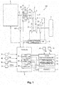
- FIG. 1 is an overall system diagram showing the driving system and the control system of the vehicle to which the control device of this embodiment is applied.
- the driving system of the vehicle is provided with: an engine (internal combustion engine) 1 that is the drive source; a torque converter 2; a variator (continuously variable transmission mechanism) 3; a forward/reverse switching mechanism 4 that has a forward clutch (engagement element) 41; a final deceleration mechanism (not illustrated); a differential (not illustrated); and a drive wheel 5.
- an engine internal combustion engine
- a torque converter 2 that is the drive source
- a forward/reverse switching mechanism 4 that has a forward clutch (engagement element) 41
- a final deceleration mechanism not illustrated
- a differential not illustrated
- a drive wheel 5 a drive wheel 5.
- a continuously variable transmission (hereafter also called “CVT” or simply “transmission”) 100 as an automatic transmission is configured.
- a mechanical oil pump 10P driven by the engine 1 is connected to the engine 1, and the oil pump 10P pressurizes the hydraulic oil [ATF (Automatic Transmission Fluid)] according to the rotation of the engine 1, and supplies it to hydraulic equipment of the transmission 100.
- ATF Automatic Transmission Fluid
- the torque converter 2 is a starting element that has a torque increasing function, and has as structural components a pump impeller 23 connected to an engine output shaft 11 via a converter housing 22, a turbine runner 24 connected to a torque converter output shaft 21, and a stator 25 provided in the case with a one way clutch interposed (not illustrated).
- the lock-up clutch 20 operates in response to differential pressure PA-PR between the torque converter apply pressure PA and the torque converter release pressure PR at the input side and output side.
- the variator 3 has a primary pulley 31, a secondary pulley 32, and a belt (or chain) 33 as a power transmitting member, and is provided with a continuously variable transmission function that changes the winding radius to the pulleys 31, 32 of the belt 33 by hydraulic pressure control of the hydraulic oil, and continuously changes the shift ratio (transmission input rotation speed/transmission output rotation speed) which is the ratio of the input rotation speed of the variator input shaft (transmission input shaft) 34 and the output rotation speed of the variator output shaft 35.
- a continuously variable transmission function that changes the winding radius to the pulleys 31, 32 of the belt 33 by hydraulic pressure control of the hydraulic oil, and continuously changes the shift ratio (transmission input rotation speed/transmission output rotation speed) which is the ratio of the input rotation speed of the variator input shaft (transmission input shaft) 34 and the output rotation speed of the variator output shaft 35.
- the torque converter output shaft 21 and the variator input shaft 34 have the same axis, but there are also cases of using a configuration with which the torque converter output shaft 21 and the variator input shaft 34 use different axes, and power connection is done via a gear mechanism, etc.
- the primary pulley 31 is configured by a fixed pulley and a slide pulley, and the slide pulley does sliding movement in the axial direction according to hydraulic pressure (primary pressure or primary pulley pressure) led to the primary hydraulic chamber.
- the secondary pulley 32 is configured by a fixed pulley and a slide pulley, and the slide pulley does sliding movement in the axial direction according to hydraulic pressure (secondary pressure or secondary pulley pressure) led to the secondary hydraulic chamber.
- the sheave surfaces which are each opposing surface of each fixed pulley and slide pulley of the primary pulley 31 and the secondary pulley 32 all form a V shape, and the belt 33 is extended across the V shaped sheave surfaces of the primary pulley 31 and the secondary pulley 32, and power is transmitted by contact with each sheave surface of both end parts of the belt 33.
- the winding radius of the belt 33 on the primary pulley 31 and the secondary pulley 32 is changed according to the sliding movement of each slide pulley of the primary pulley 31 and the secondary pulley 32, and the shift ratio is changed.
- the forward/reverse switching mechanism 4 is a mechanism for switching between forward and reverse using a planetary gear mechanism (not illustrated), and has a forward clutch (the engagement element for disconnecting/connecting transmission of the driving force of the present invention) 41 for reaching forward levels, and a reverse engagement element (not illustrated) for reaching the reverse level, and each of these friction engagement elements undergoes engagement and release according to the hydraulic pressure supplied and exhausted with each hydraulic chamber.
- the engagement element can be equipped downstream of the variator 3, and instead of the forward/reverse switching mechanism 4, for example, it is also possible to equip an auxiliary transmission mechanism which is a stepped transmission mechanism with two forward gears and one reverse gear, for example.
- the auxiliary transmission mechanism can be configured, for example, provided with a Ravigneaux planetary gear mechanism with two planetary gear carriers connected, and a plurality of friction engagement elements connected to a plurality of rotation elements that configure the Ravigneaux planetary gear mechanism, and change the linking state thereof.
- the hydraulic pressure of the primary hydraulic chamber and the secondary hydraulic chamber of the variator 3, the hydraulic chamber of each friction engagement element of the forward/reverse switching mechanism 4 and each hydraulic chamber of the lock-up clutch 20 is controlled through a hydraulic pressure control valve 10V corresponding respectively to each.
- Each hydraulic pressure control valve 10V is a solenoid valve equipped inside the hydraulic control unit 10, is operated by command signals from an ATCU 7 as a shift control means described later, and controls pressure regulation of the hydraulic oil supplied from the oil pump 10P and the supply and exhaust to each hydraulic chamber.
- this vehicle is provided with: a travel ECU 6 as a travel control means that is an electronic control unit for controlling traveling of the vehicle; an ATCU 7 as a shift control means which is an electronic control unit that controls automatic transmission; and an engine ECU 8 as an engine control means that is an electronic control unit that controls the engine 1.
- the travel ECU 6, ATCU 7, and engine ECU 8 are all configured provided with an input/output device, a storage device (ROM, RAM, etc.) with many control programs built in, a central processing device (CPU), and a timer counter, etc.
- a storage device ROM, RAM, etc.
- CPU central processing device
- a timer counter etc.
- the travel ECU 6 has a function (first control unit) 61 that executes sailing stop control when sailing stop conditions are established, and a function (second control unit) 62 that cancels the sailing stop control and returns to normal traveling when a cancellation condition for this sailing stop control is established.
- the travel ECU 6 has a function (third control unit) 63 that executes fuel cut control for stopping fuel supply to the engine 1 when the fuel cutting condition is established.
- the return control that cancels the sailing stop control by the first control unit 61 and the sailing stop control by the second control unit 62 and returns to normal traveling is implemented by the control of the transmission 100 through the ATCU 7 and the control of the engine 1 through the engine ECU 8.
- the fuel cut control by the third control unit 63 is implemented by the control of the engine 1 through the engine ECU 8.
- the ATCU 7 has: a shift ratio control unit (shift ratio control means) 71 that adjusts the hydraulic pressure of each hydraulic chamber of the variator 3 and controls the shift ratio; a forward/reverse switching control unit (forward/reverse switching control means) 72 that adjusts the hydraulic pressure of each hydraulic chamber of the forward/reverse switching mechanism 4 and switches between forward and reverse; and a lock-up clutch control unit (lock-up clutch control means) 73 that adjusts the hydraulic pressure of each hydraulic chamber of the lock-up clutch 20 and switches the engaged state.
- shift ratio control unit shift ratio control means
- forward/reverse switching control means forward/reverse switching control means
- lock-up clutch control unit lock-up clutch control means
- the engine ECU 8 controls the fuel supply amount and supply time, the opening degree of the throttle valve, and the ignition timing, etc., of the engine 1.
- the sailing stop control does control used for both controlling the transmission 100 to a neutral state (sailing control) and controlling the engine (drive source) 1 to stop, and by doing this, promotes energy saving.
- detection information from an inhibitor switch 91 for detecting the selection range of the transmission 100, a vehicle speed sensor 92, an accelerator opening degree sensor 93, and a brake sensor 94 are input to the travel ECU 6, and with the first control unit 61, sailing stop conditions are determined based on detection signals from these sensors.
- Vehicle speed Vsp is a set vehicle speed Vsp1 or greater
- condition (B) is determined from whether or not the vehicle speed signal Vsp from the vehicle speed sensor 92 is the set vehicle speed Vsp1 or greater.
- Accelerator is off of condition (C) means the accelerator operation is not implemented, and is determined from whether or not the accelerator opening signal APO from the accelerator opening degree sensor 93 indicates an opening degree of 0.
- Brake is off of condition (D) means the braking operation is not implemented, and is determined from whether or not the detection signal from the brake sensor 94 indicates that the brake is on.
- the transmission 100 is put to a neutral state, and the engine 1 is stopped.
- the shift ratio of the variator 3 is fixed at the highest state or close to the highest state, and the lock-up clutch 20 is released.
- the shift ratio is controlled along a target shift line L shown by the solid line in FIG. 2 , so if the vehicle speed is a medium to high vehicle speed, the shift ratio is in the highest state or close to the highest state shown by the dotted line.
- the sailing stop conditions include condition (B) for which the vehicle speed is medium to high vehicle speed, and condition (C) for which the accelerator is off, so when sailing stop control starts, the shift ratio is in the highest state or close to the highest state of the medium to high vehicle speed in the target shift line L shown in FIG. 2 .
- the shift ratio of the variator 3 is at the high side, compared to the primary shaft rotation speed Np (corresponding to engine speed Ne) of the variator 3, the secondary shaft rotation speed Ns (corresponding to the input side rotation speed of the forward clutch 41) of the variator 3 is a higher speed, so the input side rotation of the forward clutch 41 goes to high speed quickly, and it is possible to shorten the synchronization time with the output side of the forward clutch 41.
- the cancellation condition of the sailing stop control is that during sailing stop control, any of the sailing stop conditions of the abovementioned conditions (A) to (D) is no longer established.
- This second control unit 62 when canceling the sailing stop control, restarts the engine 1 and engages the forward clutch 41, but when the sailing stop control is canceled by the brake being on, shift ratio control of the variator 3 is added to these.
- command signals are output to the ATCU 7 and the engine ECU 8 so that the engine 1 is started, the forward clutch 41 is engaged, and the shift ratio of the variator 3 is downshifted to the lowest side.
- this downshift is performed by feedback control based on signals relating to the primary pulley rotation speed Np and the secondary pulley rotation speed Ns detected by the primary pulley rotation sensor 95 and the secondary pulley rotation sensor 96.
- downshifting the shift ratio of the variator 3 to the lowest side is provided for when the vehicle is restarted after the vehicle stops due to the brake being on, and is to ensure vehicle start performance by having the shift ratio of the variator 3 be at the lowest level or close to lowest level state.
- This kind of return control ends after completion of the start of the engine 1 and the engagement of the forward clutch 41, and thereafter goes to normal control.
- the second control unit 62 gives priority to downshifting of the variator 3 when the size of the vehicle deceleration level (hereafter also simply called deceleration level) d is a preset determination threshold value (prescribed value) d V or greater, and gives priority to engagement of the forward clutch 41 when the vehicle deceleration level d is less than the determination threshold value d V .
- the second control unit 62 outputs command signals to the ATCU 7 and the ECU 8 so as to, when the vehicle deceleration level d is the determination threshold value (prescribed value) dv or greater, start the engine 1 and implement downshifting of the variator 3, and when downshifting of the variator 3 is completed, engage the forward clutch 41.
- the second control unit 62 starts the engine 1, implements engagement of the forward clutch 41, and after engagement of the forward clutch 41 is completed, downshifts the variator 3.
- the determination threshold value d V is set to be variable according to the vehicle speed Vsp of the vehicle, and is set with a tendency so that the lower the vehicle speed Vsp, the smaller the determination threshold value d V .
- the time until the vehicle stops or the time until the rotation speed of the engine 1 decreases to an insufficient state depends on the vehicle deceleration level d and the vehicle speed Vsp at the time of deceleration start, and the larger the deceleration level d, the shorter it is, and the lower the vehicle speed Vsp at the time of deceleration start, the shorter it is. In light of that, this is set with a tendency so that the lower the vehicle speed Vsp, the smaller the determination threshold value dv.
- the downshifting of the variator 3 is set to have priority.
- the output of the engine 1 is controlled according to the accelerator opening degree APO, and the shift ratio of the variator 3 is controlled according to a preset shift map.
- Fuel cut control by the third control unit 63 is control for stopping the fuel supply to the engine 1 and suppressing the fuel consumption amount, and also for strengthening engine braking when the braking operation is performed during traveling by the vehicle at medium to high vehicle speed.
- Having the fuel cutting conditions be set to having the brake on is because the purpose is to strengthen engine braking with this fuel cut control.
- having the engine speed condition added to the fuel cutting conditions is to avoid the occurrence of stalling of the engine 1 (engine stall) during fuel recovery (restarting fuel injection) from fuel cutting.
- the fuel cutting conditions of the abovementioned conditions (a) to (e) are determined, and when the fuel cutting conditions are established, fuel cut control is implemented, and when the fuel cutting conditions become not established during fuel cut control, the fuel cut control is ended.
- the lock-up clutch 20 can be completely engaged (engagement).
- This fuel cut control may be started after going through return control from sailing stop control by operating the brake from off to on during sailing stop control.
- the vehicle control device of an embodiment of the present invention has the configuration described above, so vehicle control is implemented as shown in the flow chart of FIG. 4 , for example.
- vehicle control is implemented as shown in the flow chart of FIG. 4 , for example.
- the vehicle starts by its key being switched on, a prescribed control cycle is repeatedly implemented, and it ends by the key being switched off.
- step S10 a determination is made of whether in sailing stop control or not (step S10), and if in sailing stop control, a determination is made of whether sailing stop cancellation conditions are established (step S20), and if not in sailing stop control, a determination is made of whether sailing stop conditions are established (step S40).
- step S20 For determination of the sailing stop cancellation condition by step S20, a determination is made for the abovementioned conditions (A) to (D), and if any of conditions (A) to (D) is not established, it is determined that the sailing stop cancellation condition is established.
- step S40 For the determination of sailing stop conditions by step S40, a determination is made regarding the abovementioned conditions (A) to (D), and if all of conditions (A) to (D) are established, it is determined that the sailing stop conditions are established.
- step S60 When not during sailing stop control, and when it is determined using step S40 that the sailing stop conditions are not established, normal control (step S60) is implemented.
- fuel cut control is performed that stops the fuel supply to engine 1, suppressing the fuel consumption amount, and also strengthening engine braking.
- sailing stop control when it is determined by step S20 that the sailing stop cancellation condition is established, and when not in sailing stop control, when it is determined by step S40 that sailing stop conditions are established, sailing stop control (step S50) is implemented.
- control to turn off (release) the forward clutch 41 and put the transmission 100 in the neutral state step S502
- control to stop the engine 1 step S504
- control to fix the shift ratio to highest level step S506
- control to turn off (release) the lock-up clutch 20 step S508.
- step S30 is implemented that cancels the sailing stop control and returns to normal traveling.
- step S302 starting of the return control and also start control of the engine 1 are performed (step S302), a determination is made of whether the sailing stop cancellation condition is established by the brake being on (step S304), and if the sailing stop cancellation condition is established by the brake being on, a determination is made of whether the vehicle deceleration level d is the determination threshold value d V or greater for each vehicle speed (step S306).
- Engagement control of the forward clutch 41 (step S316) is performed until it is determined at step S318 that engagement of the forward clutch 41 is completed.
- the processes of step S316 and step S318 are performed at prescribed control cycles until it is determined that engagement is complete.
- step S318 when it is determined that engagement is completed, return control ends, and at the next control cycle, via step S10 and step S40, the normal control is implemented (step S60).
- step S308 downshift control of the variator 3 is implemented (step S308), downshifting of the variator 3 progresses, and a determination is made of whether the shift ratio is at the lowest level (step S310).
- step S308 The downshift control of the variator 3 of step S308 is performed until it is determined at step S310 that the shift ratio has reached the lowest level.
- step S308 and step S310 is performed at prescribed control cycles until it is determined to be the lowest level at step S310.
- step S310 When a determination of lowest level is made at step S310, the engagement control of the forward clutch 41 is performed (step S312), and a determination is made of whether or not engagement of the forward clutch 41 is completed (step S314). Though not shown in FIG. 4 , even before a determination of lowest level is made, even when the accelerator pedal is pressed during downshifting of the variator, the process moves to the clutch engagement process.
- step S312 The engagement control of the forward clutch 41 of step S312 is performed until it is determined at step S314 that engagement of the forward clutch 41 is complete.
- the processes of step S312 and step S314 are performed at prescribed control cycles until it is determined that engagement is complete.
- step S60 normal control
- SS indicates the sailing stop control state
- SS return indicates the return control state
- stop indicates the vehicle stop state
- FC indicates the fuel cut control state.
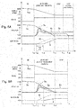
- FIG. 5 shows each variation example of the vehicle speed, brake, each rotation speed, and shift ratio when the sailing stop control cancellation condition is established by the brake being on, and when the vehicle deceleration level d when this condition is established is threshold value d V or greater. (a) shows a case when this control is applied, and (b) shows a case when this control is not applied.
- the vehicle deceleration level d when the cancellation condition is established is the threshold value dv or greater, and to perform return control with downshifting of the variator 3 prioritized, the engine 1 start operation is performed immediately after the start of return control, and also the operation of downshifting the target shift ratio Rt to the lowest side is started.
- the engine speed Ne rises, and together with that, the primary shaft rotation speed Np of the variator 3 and the secondary shaft rotation speed Ns of the variator 3 rise.
- the primary shaft rotation speed Np is raised so as to follow the engine speed Ne, and the secondary shaft rotation speed Ns is raised so as to be proportional with the primary shaft rotation speed Np with the shift ratio at the start of return control (lowest level or approximately lowest level).
- the actual shift ratio R is also changed to the downshift side from time t 13 following the target shift ratio Rt, and the secondary shaft rotation speed Ns decreases relative to the primary shaft rotation speed Np.
- the forward clutch 41 is in a released state and the variator 3 is able to rotate, so if the engine 1 is operating, it is possible to ensure the discharge pressure of the oil pump 10P, and possible to engage the forward clutch 41.
- the vehicle stops in a state for which the shift ratio of the variator 3 is at its lowest level. For this reason, it is possible to perform restart of the vehicle in a state with the shift ratio at the lowest level, and possible to ensure good starting performance of the vehicle.
- the start operation of the engine 1 is performed immediately after return control start time t 11 , and furthermore at time t 12 at which the engine 1 start completion is determined, an instruction is given to engage the forward clutch 41 and to change the target shift ratio Rt to the downshift side.
- the engagement responsiveness of the forward clutch 41 is higher than the downshift responsiveness of the variator 3, so the engagement of the forward clutch 41 is completed at time t 13 ' which is earlier than the completion of downshifting, and the variator 3 secondary shaft rotation speed Ns matches the transmission output shaft rotation speed No.
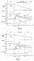
- FIG. 6 shows examples of each change of the vehicle speed, brake, each rotation speed, and shift ratio when at time t 21 , the sailing stop control cancellation condition is established by the brake being on, and the deceleration level d of the vehicle when this condition is established is less than the threshold value d V .
- the engine 1 start operation is performed immediately after the return control start time t 21 , and furthermore, at time t 22 after the engine 1 start completion determination, the operation of engaging the forward clutch 41 starts.
- the target shift ratio Rt is downshifted to the lowest side.
- the engagement of the forward clutch 41 is performed in a state with the variator 3 shift ratio at the high side, so it is possible to quickly complete rotation synchronization between input and output before engagement of the forward clutch 41, and possible to quickly engage the forward clutch 41.
- FIG. 7 shows examples of each variation of the vehicle speed, brake, each rotation speed, and shift ratio when the sailing stop control cancellation condition is established at time t 31 by the brake being on, and the vehicle deceleration level d when this condition is established is less than the threshold value d V , and when the vehicle speed is higher or the vehicle deceleration level d is smaller than the case in FIG. 6 .
- the engine 1 start operation is performed immediately after return control start time t 31 , and also, the engagement operation of the forward clutch 41 starts at time t 32 after it is determined that the engine 1 start is complete.
- the target shift ratio Rt is downshifted to the lowest level side.
- engagement of the forward clutch 41 is performed with the variator 3 shift ratio in a high side state, so it is possible to quickly complete the rotation synchronization between input and output before engagement of the forward clutch 41, and it is possible to engage the forward clutch 41 quickly.
- condition (E) when condition (E) is added, when the accelerator is turned off, the shift ratio moves to the highest level, sailing stop control is implemented waiting for this, and it is possible to further suppress the decrease in vehicle speed with the sailing stop control thereafter.
- step S304 in FIG. 4 having the sailing stop cancellation condition established by having the brake on is added (step S304 in FIG. 4 ), but normally, unless the brake is on, it is thought that the vehicle deceleration level d will not become the threshold value d V or greater, so the determination of the prerequisite can be omitted.
- the engagement element for disconnecting/connecting the transmission of the driving force of the present invention is the forward clutch 41, but as this engagement element, typically, with the forward engagement element as the focus, instead of the forward/reverse switching mechanism 4, for example, it is possible to use a forward engagement element such as an auxiliary transmission mechanism that is a stepped transmission mechanism with two forward gears and one reverse gear, or each engagement element of two forward gears, the first forward gear and the second forward gear.
- a forward engagement element such as an auxiliary transmission mechanism that is a stepped transmission mechanism with two forward gears and one reverse gear, or each engagement element of two forward gears, the first forward gear and the second forward gear.
- control means was configured with hardware from each control unit of the travel ECU 6 as the travel control means, the ATCU 7 as the shift control means, and the engine ECU 8 as the engine control means, but the hardware configuration for these travel control means, shift control means, and engine control means is not limited to this, and for example, it is possible to use various configurations such as providing each function of the travel control means, shift control means, and engine control means inside one control unit, etc.
Landscapes
- Engineering & Computer Science (AREA)
- General Engineering & Computer Science (AREA)
- Mechanical Engineering (AREA)
- Chemical & Material Sciences (AREA)
- Combustion & Propulsion (AREA)
- Transportation (AREA)
- Automation & Control Theory (AREA)
- Physics & Mathematics (AREA)
- Mathematical Physics (AREA)
- Control Of Transmission Device (AREA)
- Control Of Driving Devices And Active Controlling Of Vehicle (AREA)
- Control Of Vehicle Engines Or Engines For Specific Uses (AREA)
Abstract
Description
- The present invention relates to a vehicle control device for implementing sailing stop control that sets a transmission to a neutral state under prescribed control conditions, and also stops a drive source.
- In recent years, there has been developed a technique (sailing stop control) that, when prescribed control conditions are established while a vehicle is traveling, is used for both control of a transmission to a neutral state (sailing control) and control to stop a drive source, promoting energy saving (see Patent Document 1).
- The conditions (A) to (D) noted hereafter are included as AND conditions in the control conditions of this sailing stop control.
- (A) Forward range is selected.
- (B) Vehicle speed is a set vehicle speed or greater (medium to high vehicle speed).
- (C) Accelerator is off.
- (D) Brake is off.
- However, when the vehicle is equipped with a continuously variable transmission, provision is such that before stopping the vehicle, the shift ratio of a variator of the continuously variable transmission is downshifted to the lowest level, and restart is done thereafter.
- In such a vehicle, when there is sudden deceleration from sailing stop control and the vehicle reaches a stop, it was found that there are cases when the vehicle cannot downshift to the lowest level before stopping.
- The causes of this are analyzed.
- With sailing stop control, in a state for which the vehicle speed of the abovementioned condition (B) is a set vehicle speed or greater (medium to high speed), the drive source is stopped, the shift ratio of the variator in the medium to high vehicle speed is at the high side, and the transmission has the forward clutch released and is in neutral.
- When a sudden braking operation is performed from sailing stop control, sailing stop control is cancelled, return control is performed that operates the drive source and engages the forward clutch, and after the forward clutch is engaged, the variator shift ratio is downshifted to the lowest level.
- Engaging the forward clutch before downshifting the variator is done because it is possible to do rotation synchronization of the forward clutch more quickly than when the shift ratio of the variator is on the high side.
- However, when attempting to downshift the variator after engagement of the forward clutch in this way, the vehicle stops before it is possible to downshift to the lowest level of the target shift ratio.
- The variator performs changing (shifting) of the shift ratio while rotating, so shifting takes more time the slower the rotational speed, and in particular with transmissions of a configuration for which the forward clutch is arranged at the downstream side of the variator, when the vehicle is stopped in a state with the forward clutch engaged, the variator also stops, and rotation is not possible, so it becomes completely impossible to shift the variator.
- Therefore, if the vehicle speed when a sudden braking operation is performed from sailing stop control is high speed, it is possible to complete the shift operation while the variator is rotating at a rotational speed that is a certain level or higher, but if the vehicle speed is medium speed, there are cases when the vehicle stops before the shift operation is completed.
- Also, hydraulic pressure is generated by a hydraulic pump driven by the vehicle drive source engine, and when the variator is controlled using this hydraulic pressure, when the vehicle speed decreases and engine rotation decreases, the necessary hydraulic pressure cannot be obtained, and shifting of the variator is difficult.
- Therefore, it is necessary to complete downshifting of the variator in a state for which the necessary hydraulic pressure can be obtained.
- Patent Document 1: Japanese Unexamined Patent Publication No.
2013-213557 - The present invention was created considering this kind of problem, and its purpose is, in a vehicle provided with a continuously variable transmission having a variator, to provide a vehicle control device that is able to improve the low return performance for downshifting the shift ratio of the variator to the lowest level before the vehicle stops, even when a braking operation is performed during sailing stop control.
- To achieve the abovementioned purpose, the vehicle control device of the present invention is a control device of a vehicle which has: a drive source; and an automatic transmission which has an engagement element for disconnecting/connecting the transmission of the driving force and a variator placed further upstream than the engagement element, and which is connected to the drive source, said vehicle control device having: a first control unit that executes sailing stop control that, when sailing stop conditions are established, stops the drive source and also puts the automatic transmission into a neutral state; and a second control unit that, when a prescribed sailing stop cancellation condition among the sailing stop cancellation conditions is established, and the sailing stop control is cancelled, when the size of the deceleration level of the vehicle is a prescribed value or greater, starts the drive source and implements downshifting of the variator, and engages the engagement element after downshifting is complete.
- When the sailing stop control is cancelled, and when the size of the vehicle deceleration level is less than the prescribed value, the second control unit preferably starts the drive source and engages the engagement element, and moves to control of the variator after engaging of the engagement element.
- It is preferable that the prescribed value be set to vary according to the travel speed of the vehicle when cancelling the sailing stop control.
- Included as AND conditions in the sailing stop conditions are: the selection range of the automatic transmission being the forward range, the traveling speed of the vehicle being a set speed or greater, the accelerator of the vehicle being off, and the brake of the vehicle being off, with the sailing stop cancellation condition being that any of the sailing stop conditions are no longer established, and the prescribed sailing stop cancellation condition being that the brake is on being preferable.
- Once starting of the drive source and engagement of the engagement element by the second control unit is completed, normal control is preferably implemented in which the engagement of the engagement element is maintained, output of the drive source is controlled according to the accelerator opening degree of the vehicle, and the shift ratio of the variator is controlled according to a preset shift map.
- The drive source is an internal combustion engine, and having a third control unit that implements fuel cut control that stops fuel supply to the internal combustion engine if a fuel cutting condition is established is preferable.
- With the present invention, when sailing stop control ends in a state with a high deceleration level of the vehicle due to sudden braking, etc., the drive source restarts, engagement of the engagement element is given priority, and shifting of the variator is completed, so the low return performance of the variator is improved, it is possible to have the shift ratio of the variator reach the lowest level or be as close as possible to the lowest level by the time the vehicle stops, and possible to ensure restart capability of the vehicle.
-
-
FIG. 1 is a system diagram showing the main parts of the driving system and control system of the vehicle to which the control device of an embodiment of the present invention is applied. -
FIG. 2 is a diagram showing a control map using the vehicle control of the embodiment of the present invention. -
FIG. 3 is a shift chart for explaining the shift ratio characteristics of the variator related to the vehicle control of the embodiment of the present invention. -
FIG. 4 is a flow chart for explaining the vehicle control of the embodiment of the present invention. -
FIG. 5 is a time chart for explaining the return control (variator downshift priority) of the vehicle control of the embodiment of the present invention. -
FIG. 6 is a time chart for explaining the return control (forward clutch engagement priority and vehicle stop) of the vehicle control of the embodiment of the present invention. -
FIG. 7 is a time chart for explaining the return control (forward clutch engagement priority and vehicle travel continuation) of the vehicle control of the embodiment of the present invention. - Hereafter, embodiments of the present invention are explained while referring to the drawings. The embodiments shown hereafter are merely examples, and are not intended to exclude application of various changes or technology not shown in the embodiments below. Each configuration of the embodiments hereafter can be implemented with various changes in a range that does not stray from the gist thereof, and it is possible to make choices as necessary, or combine as appropriate.
-
FIG. 1 is an overall system diagram showing the driving system and the control system of the vehicle to which the control device of this embodiment is applied. - As shown in
FIG. 1 , the driving system of the vehicle is provided with: an engine (internal combustion engine) 1 that is the drive source; atorque converter 2; a variator (continuously variable transmission mechanism) 3; a forward/reverse switching mechanism 4 that has a forward clutch (engagement element) 41; a final deceleration mechanism (not illustrated); a differential (not illustrated); and adrive wheel 5. - By storing the
torque converter 2, thevariator 3, and the forward/reverse switching mechanism 4 inside a transmission case, a continuously variable transmission (hereafter also called "CVT" or simply "transmission") 100 as an automatic transmission is configured. - A
mechanical oil pump 10P driven by theengine 1 is connected to theengine 1, and theoil pump 10P pressurizes the hydraulic oil [ATF (Automatic Transmission Fluid)] according to the rotation of theengine 1, and supplies it to hydraulic equipment of thetransmission 100. - The
torque converter 2 is a starting element that has a torque increasing function, and has as structural components apump impeller 23 connected to anengine output shaft 11 via aconverter housing 22, aturbine runner 24 connected to a torqueconverter output shaft 21, and astator 25 provided in the case with a one way clutch interposed (not illustrated). - The
torque converter 2, when the torque increasing function is not needed, has a lock-up clutch 20 that can directly connect the engine output shaft 11 (= torque converter input shaft) and the torqueconverter output shaft 21. - Though not illustrated, the lock-
up clutch 20 operates in response to differential pressure PA-PR between the torque converter apply pressure PA and the torque converter release pressure PR at the input side and output side. - In other words, when the release pressure PR is higher than the apply pressure PA, the lock-up
clutch 20 is released, and when the release pressure PR is lower than the apply pressure PA, the lock-upclutch 20 is engaged. - Therefore, by adjusting the release pressure PR and the apply pressure PA, between the input/output elements of the
torque converter 20 can be switched between a released state, a completely engaged state (directly connected state), and a slipped engagement state that is intermediate to these. - The
variator 3 has aprimary pulley 31, asecondary pulley 32, and a belt (or chain) 33 as a power transmitting member, and is provided with a continuously variable transmission function that changes the winding radius to thepulleys belt 33 by hydraulic pressure control of the hydraulic oil, and continuously changes the shift ratio (transmission input rotation speed/transmission output rotation speed) which is the ratio of the input rotation speed of the variator input shaft (transmission input shaft) 34 and the output rotation speed of thevariator output shaft 35. - With
FIG. 1 , the torqueconverter output shaft 21 and thevariator input shaft 34 have the same axis, but there are also cases of using a configuration with which the torqueconverter output shaft 21 and thevariator input shaft 34 use different axes, and power connection is done via a gear mechanism, etc. - Though details are not illustrated, the
primary pulley 31 is configured by a fixed pulley and a slide pulley, and the slide pulley does sliding movement in the axial direction according to hydraulic pressure (primary pressure or primary pulley pressure) led to the primary hydraulic chamber. - Similarly, the
secondary pulley 32 is configured by a fixed pulley and a slide pulley, and the slide pulley does sliding movement in the axial direction according to hydraulic pressure (secondary pressure or secondary pulley pressure) led to the secondary hydraulic chamber. - The sheave surfaces which are each opposing surface of each fixed pulley and slide pulley of the
primary pulley 31 and thesecondary pulley 32 all form a V shape, and thebelt 33 is extended across the V shaped sheave surfaces of theprimary pulley 31 and thesecondary pulley 32, and power is transmitted by contact with each sheave surface of both end parts of thebelt 33. - The winding radius of the
belt 33 on theprimary pulley 31 and thesecondary pulley 32 is changed according to the sliding movement of each slide pulley of theprimary pulley 31 and thesecondary pulley 32, and the shift ratio is changed. - The forward/
reverse switching mechanism 4 is a mechanism for switching between forward and reverse using a planetary gear mechanism (not illustrated), and has a forward clutch (the engagement element for disconnecting/connecting transmission of the driving force of the present invention) 41 for reaching forward levels, and a reverse engagement element (not illustrated) for reaching the reverse level, and each of these friction engagement elements undergoes engagement and release according to the hydraulic pressure supplied and exhausted with each hydraulic chamber. - In the case of this control device, the engagement element can be equipped downstream of the
variator 3, and instead of the forward/reverse switching mechanism 4, for example, it is also possible to equip an auxiliary transmission mechanism which is a stepped transmission mechanism with two forward gears and one reverse gear, for example. - In this case, the auxiliary transmission mechanism can be configured, for example, provided with a Ravigneaux planetary gear mechanism with two planetary gear carriers connected, and a plurality of friction engagement elements connected to a plurality of rotation elements that configure the Ravigneaux planetary gear mechanism, and change the linking state thereof.
- In regards to this kind of
transmission 100, the hydraulic pressure of the primary hydraulic chamber and the secondary hydraulic chamber of thevariator 3, the hydraulic chamber of each friction engagement element of the forward/reverse switching mechanism 4 and each hydraulic chamber of the lock-up clutch 20 is controlled through a hydraulicpressure control valve 10V corresponding respectively to each. - Each hydraulic
pressure control valve 10V is a solenoid valve equipped inside thehydraulic control unit 10, is operated by command signals from an ATCU 7 as a shift control means described later, and controls pressure regulation of the hydraulic oil supplied from theoil pump 10P and the supply and exhaust to each hydraulic chamber. - As control means for controlling the vehicle, this vehicle is provided with: a
travel ECU 6 as a travel control means that is an electronic control unit for controlling traveling of the vehicle; anATCU 7 as a shift control means which is an electronic control unit that controls automatic transmission; and anengine ECU 8 as an engine control means that is an electronic control unit that controls theengine 1. - The
travel ECU 6,ATCU 7, andengine ECU 8 are all configured provided with an input/output device, a storage device (ROM, RAM, etc.) with many control programs built in, a central processing device (CPU), and a timer counter, etc. - The
travel ECU 6 has a function (first control unit) 61 that executes sailing stop control when sailing stop conditions are established, and a function (second control unit) 62 that cancels the sailing stop control and returns to normal traveling when a cancellation condition for this sailing stop control is established. - Furthermore, the
travel ECU 6 has a function (third control unit) 63 that executes fuel cut control for stopping fuel supply to theengine 1 when the fuel cutting condition is established. - The return control that cancels the sailing stop control by the
first control unit 61 and the sailing stop control by thesecond control unit 62 and returns to normal traveling is implemented by the control of thetransmission 100 through theATCU 7 and the control of theengine 1 through theengine ECU 8. - Also, the fuel cut control by the
third control unit 63 is implemented by the control of theengine 1 through theengine ECU 8. - The
ATCU 7 has: a shift ratio control unit (shift ratio control means) 71 that adjusts the hydraulic pressure of each hydraulic chamber of thevariator 3 and controls the shift ratio; a forward/reverse switching control unit (forward/reverse switching control means) 72 that adjusts the hydraulic pressure of each hydraulic chamber of the forward/reverse switching mechanism 4 and switches between forward and reverse; and a lock-up clutch control unit (lock-up clutch control means) 73 that adjusts the hydraulic pressure of each hydraulic chamber of the lock-upclutch 20 and switches the engaged state. - The
engine ECU 8 controls the fuel supply amount and supply time, the opening degree of the throttle valve, and the ignition timing, etc., of theengine 1. - The sailing stop control does control used for both controlling the
transmission 100 to a neutral state (sailing control) and controlling the engine (drive source) 1 to stop, and by doing this, promotes energy saving. - For the sailing stop conditions for performing this sailing stop control, the following conditions (A) to (D) are provided as AND conditions.
- (A) Forward range is selected.
- (B) Vehicle speed (vehicle traveling speed) Vsp is a set vehicle speed (set speed) Vsp1 or greater (medium to high vehicle speed).
- (C) Accelerator is off.
- (D) Brake is off.
- For this reason, detection information from an
inhibitor switch 91 for detecting the selection range of thetransmission 100, avehicle speed sensor 92, an acceleratoropening degree sensor 93, and abrake sensor 94 are input to thetravel ECU 6, and with thefirst control unit 61, sailing stop conditions are determined based on detection signals from these sensors. - "Forward range is selected" of condition (A) is determined from whether or not the selection range signal S from the
inhibitor switch 91 correlates to the forward range. - "Vehicle speed Vsp is a set vehicle speed Vsp1 or greater" of condition (B) is determined from whether or not the vehicle speed signal Vsp from the
vehicle speed sensor 92 is the set vehicle speed Vsp1 or greater. - "Accelerator is off" of condition (C) means the accelerator operation is not implemented, and is determined from whether or not the accelerator opening signal APO from the accelerator
opening degree sensor 93 indicates an opening degree of 0. - "Brake is off" of condition (D) means the braking operation is not implemented, and is determined from whether or not the detection signal from the
brake sensor 94 indicates that the brake is on. - Having all of the abovementioned sensors that are involved in sailing stop control be normal is a prerequisite, and this prerequisite and having all of the abovementioned conditions (A) to (D) be established is a condition for performing sailing stop control.
- With the
first control unit 61, as the sailing stop control, thetransmission 100 is put to a neutral state, and theengine 1 is stopped. At this time, the shift ratio of thevariator 3 is fixed at the highest state or close to the highest state, and the lock-up clutch 20 is released. - With normal shift control of the
variator 3, when the accelerator is off, the shift ratio is controlled along a target shift line L shown by the solid line inFIG. 2 , so if the vehicle speed is a medium to high vehicle speed, the shift ratio is in the highest state or close to the highest state shown by the dotted line. - The sailing stop conditions include condition (B) for which the vehicle speed is medium to high vehicle speed, and condition (C) for which the accelerator is off, so when sailing stop control starts, the shift ratio is in the highest state or close to the highest state of the medium to high vehicle speed in the target shift line L shown in
FIG. 2 . - During sailing stop control, while the
forward clutch 41 is released on the one hand, during return control when the sailing stop control is cancelled and there is a return to normal control, the released forward clutch 41 is engaged, so there is a desire to perform this engagement quickly. As a result, it is possible to make the return to normal control earlier, and possible to improve the vehicle driving performance. - To engage the
forward clutch 41, it is necessary to do rotation synchronization between input and output before engaging theforward clutch 41, and it is possible to have the high side of the shift ratio of thevariator 3 complete rotation synchronization more quickly, and possible to perform engaging of the forward clutch 41 quickly. - In other words, when returning from sailing stop control to normal control, the
engine 1 is started and theforward clutch 41 is engaged, but the output side (drivewheel 5 side) of theforward clutch 41 rotates at a comparatively high speed correlating to the vehicle speed Vsp, and meanwhile, the input side (variator 3 side andengine 1 side) of the forward clutch 41 starts rotating from a stopped state. - If the shift ratio of the
variator 3 is at the high side, compared to the primary shaft rotation speed Np (corresponding to engine speed Ne) of thevariator 3, the secondary shaft rotation speed Ns (corresponding to the input side rotation speed of the forward clutch 41) of thevariator 3 is a higher speed, so the input side rotation of theforward clutch 41 goes to high speed quickly, and it is possible to shorten the synchronization time with the output side of theforward clutch 41. - Also, the cancellation condition of the sailing stop control is that during sailing stop control, any of the sailing stop conditions of the abovementioned conditions (A) to (D) is no longer established.
- With the
second control unit 62, when any of the sailing stop conditions is no longer established, the cancellation condition for the sailing stop control is regarded as being established, sailing stop control is canceled, and there is a return to normal control. - This
second control unit 62, when canceling the sailing stop control, restarts theengine 1 and engages theforward clutch 41, but when the sailing stop control is canceled by the brake being on, shift ratio control of thevariator 3 is added to these. - In other words, with the
second control unit 62, when the brake is on and the sailing stop cancellation condition is established, command signals are output to theATCU 7 and theengine ECU 8 so that theengine 1 is started, theforward clutch 41 is engaged, and the shift ratio of thevariator 3 is downshifted to the lowest side. - With the shift
ratio control unit 71 of theATCU 7, this downshift is performed by feedback control based on signals relating to the primary pulley rotation speed Np and the secondary pulley rotation speed Ns detected by the primarypulley rotation sensor 95 and the secondarypulley rotation sensor 96. - In this way, downshifting the shift ratio of the
variator 3 to the lowest side is provided for when the vehicle is restarted after the vehicle stops due to the brake being on, and is to ensure vehicle start performance by having the shift ratio of thevariator 3 be at the lowest level or close to lowest level state. - This kind of return control ends after completion of the start of the
engine 1 and the engagement of theforward clutch 41, and thereafter goes to normal control. - When there is sailing stop cancellation due to the brake being on, in addition to the engagement of the
forward clutch 41, downshifting of thevariator 3 is performed, but with thesecond control unit 62, during this return control, the two processes of the engagement of theforward clutch 41 and the downshifting of thevariator 3 are implemented with priority sequence given based on the size of the deceleration level of the vehicle (scalar quantity of the deceleration level, specifically, the absolute value) d. - In other words, the
second control unit 62 gives priority to downshifting of thevariator 3 when the size of the vehicle deceleration level (hereafter also simply called deceleration level) d is a preset determination threshold value (prescribed value) dV or greater, and gives priority to engagement of the forward clutch 41 when the vehicle deceleration level d is less than the determination threshold value dV. - Therefore, when the sailing stop cancellation condition is established, the
second control unit 62 outputs command signals to theATCU 7 and theECU 8 so as to, when the vehicle deceleration level d is the determination threshold value (prescribed value) dv or greater, start theengine 1 and implement downshifting of thevariator 3, and when downshifting of thevariator 3 is completed, engage theforward clutch 41. - Also, when the sailing stop cancelation condition is established, when the vehicle deceleration level d is less than the determination threshold value dV, the
second control unit 62 starts theengine 1, implements engagement of theforward clutch 41, and after engagement of theforward clutch 41 is completed, downshifts thevariator 3. - In this way, when the vehicle deceleration level d is the determination threshold value dV or greater, downshifting of the
variator 3 has priority, so even if the time until the vehicle decelerates and stops is extremely short, theforward clutch 41 is not engaged, and thevariator 3 is not connected to the wheels, so a state for which thevariator 3 is rotated by the engine I is ensured. As a result, the low return performance of thevariator 3 is improved, it is possible to downshift the shift ratio of thevariator 3 to the lowest level or close to that, and the vehicle start performance thereafter is ensured. - To change the shift ratio of the
variator 3, it is necessary for thevariator 3 to be rotating and for the discharge pressure of theoil pump 10P to be ensured at a minimum level or greater. Also, to ensure that the discharge pressure of theoil pump 10P is a minimum level or greater, it is necessary to sufficiently ensure that the rotation speed of theengine 1 is the necessary rotation speed or greater. - Therefore, when the vehicle has stopped, or when the rotation speed of the
engine 1 is insufficient and there is not sufficient discharge pressure of theoil pump 10P (in this case, if hydraulic pressure is supplied to theforward clutch 4, there is a further reduction in the supply of hydraulic pressure to thevariator 3, and shifting of thevariator 3 becomes extremely difficult), it becomes impossible to change the shift ratio of thevariator 3. - In light of that, when there is no spare time until the vehicle stops and the rotation speed of the
engine 1 decreases to an insufficient state, before the vehicle stops, and while it is possible for the rotation speed of theengine 1 to ensure the discharge pressure of theoil pump 10P at a minimum limit or greater, downshifting of thevariator 3 is implemented with priority. - However, when there is time to spare until the vehicle stops or the rotation speed of the
engine 1 decreases to an insufficient state, the engagement of theforward clutch 41 has priority, and even if downshifting of thevariator 3 starts after engagement of the clutch 41 is completed, it is possible to complete downshifting of thevariator 3 until the vehicle stops or until the rotation speed of theengine 1 decreases. - This is because, as described previously, rotation synchronization is necessary between input and output before engaging the
forward clutch 41, and it is possible for the high side of the shift ratio of thevariator 3 to complete rotation synchronization faster. and possible for the engagement of the forward clutch 41 to be done faster. - As shown in the determination map of
FIG. 3 , the determination threshold value dV is set to be variable according to the vehicle speed Vsp of the vehicle, and is set with a tendency so that the lower the vehicle speed Vsp, the smaller the determination threshold value dV. - This is because the time until the vehicle stops or the time until the rotation speed of the
engine 1 decreases is related not only to the vehicle deceleration level d at the point when the sailing stop cancellation condition is established, but also to the vehicle speed Vsp at that point. - In other words, the time until the vehicle stops or the time until the rotation speed of the
engine 1 decreases to an insufficient state depends on the vehicle deceleration level d and the vehicle speed Vsp at the time of deceleration start, and the larger the deceleration level d, the shorter it is, and the lower the vehicle speed Vsp at the time of deceleration start, the shorter it is. In light of that, this is set with a tendency so that the lower the vehicle speed Vsp, the smaller the determination threshold value dv. - With the determination map shown in
FIG. 3 , in the high speed range for which the vehicle speed Vsp is at a prescribed vehicle speed value Vsp2 or greater, engagement of theforward clutch 41 is set to have priority regardless of the deceleration level d. - This is because in this kind of high speed range of the vehicle, it is sufficient to decelerate while tracing the highest level line in the target shift line L shown by a solid line in
FIG. 2 , so downshifting of thevariator 3 is sufficiently completed even after engagement of theforward clutch 41. - Also, in the medium speed range for which the vehicle speed Vsp is at the prescribed vehicle speed value Vsp2 or less, as long as the deceleration level d is not slow deceleration of a prescribed low deceleration level d1 or less, the downshifting of the
variator 3 is set to have priority. - This is because with this kind of medium speed range, as shown by the dotted line in
FIG. 2 , a case is assumed of decelerating while tracing the highest level line skewed from the target shift line L, and as long as the deceleration level d is not slow deceleration of a prescribed low deceleration level d1 or less, there is a high risk of not being able to complete downshifting of thevariator 3 after engaging of theforward clutch 41. - With normal control, while maintaining the engaged state of the
forward clutch 41, the output of theengine 1 is controlled according to the accelerator opening degree APO, and the shift ratio of thevariator 3 is controlled according to a preset shift map. - When sailing stop control by the
first control unit 61 is implemented, normal control is implemented after going through return control (cancelation of sailing stop control) by thesecond control unit 62. - As noted previously, return control ends at the stage when the engagement of the
forward clutch 41 is completed, so when downshifting of thevariator 3 has priority, there is a return to normal control when downshifting of thevariator 3 is completed and furthermore, engagement of theforward clutch 41 is completed. - Also, when engagement of the
forward clutch 41 has priority, there is a return to normal control if the engagement of theforward clutch 41 is completed, but even when returned to normal control, if the brake on state continues, downshifting of thevariator 3 is implemented. - Fuel cut control by the
third control unit 63 is control for stopping the fuel supply to theengine 1 and suppressing the fuel consumption amount, and also for strengthening engine braking when the braking operation is performed during traveling by the vehicle at medium to high vehicle speed. - As fuel cutting conditions for performing this fuel cut control, the following conditions (a) to (e) are provided as AND conditions.
- (a) Forward range is selected.
- (b) Vehicle speed Vsp is the set vehicle speed Vsp2 or greater (medium to high vehicle speed).
- (c) The accelerator is off.
- (d) The brake is on.
- (e) The engine speed Ne is a set recovery rotation speed Ner or greater.
- The big differences are that in contrast to having the brake off as one of the conditions with the sailing stop conditions, with the fuel cutting conditions, having the brake on is one condition, and the engine speed condition is added with fuel cutting conditions.
- Having the fuel cutting conditions be set to having the brake on is because the purpose is to strengthen engine braking with this fuel cut control.
- Also, having the engine speed condition added to the fuel cutting conditions is to avoid the occurrence of stalling of the engine 1 (engine stall) during fuel recovery (restarting fuel injection) from fuel cutting.
- With the
third control unit 61, based on detections signals from each of the sensors, the fuel cutting conditions of the abovementioned conditions (a) to (e) are determined, and when the fuel cutting conditions are established, fuel cut control is implemented, and when the fuel cutting conditions become not established during fuel cut control, the fuel cut control is ended. - With this fuel cut control, with the
transmission 100 in a power transmitting state and with a decrease in the power transmitting loss, fuel supply to theengine 1 is stopped, and the shift ratio of thevariator 3 is downshifted to the low side. - To put the
transmission 100 in a power transmitting state, it is sufficient for the forward clutch 41 to be engaged, and to decrease the power transmitting loss of thetransmission 100, the lock-up clutch 20 can be completely engaged (engagement). - In this way, when the lock-up clutch 20 is completely engaged, there is the risk of engine stall occurring if the engine speed Ne is not high to a certain degree at the time of fuel recovery, and because of that, the engine speed condition (e) was added to the fuel cutting conditions.
- This fuel cut control may be started after going through return control from sailing stop control by operating the brake from off to on during sailing stop control.
- The vehicle control device of an embodiment of the present invention has the configuration described above, so vehicle control is implemented as shown in the flow chart of
FIG. 4 , for example. With the flow chart inFIG. 4 , the vehicle starts by its key being switched on, a prescribed control cycle is repeatedly implemented, and it ends by the key being switched off. - As shown in
FIG. 4 , first, a determination is made of whether in sailing stop control or not (step S10), and if in sailing stop control, a determination is made of whether sailing stop cancellation conditions are established (step S20), and if not in sailing stop control, a determination is made of whether sailing stop conditions are established (step S40). - For determination of the sailing stop cancellation condition by step S20, a determination is made for the abovementioned conditions (A) to (D), and if any of conditions (A) to (D) is not established, it is determined that the sailing stop cancellation condition is established.
- For the determination of sailing stop conditions by step S40, a determination is made regarding the abovementioned conditions (A) to (D), and if all of conditions (A) to (D) are established, it is determined that the sailing stop conditions are established.
- When not during sailing stop control, and when it is determined using step S40 that the sailing stop conditions are not established, normal control (step S60) is implemented.
- With this normal control, while maintaining the engaged state of the
forward clutch 41, the output of theengine 1 is controlled according to the accelerator opening degree APO, and the shift ratio of thevariator 3 is controlled according to a preset shift map. - Also, during normal control, during travel of the vehicle at medium to high vehicle speed, when a braking operation is performed and fuel cutting conditions are established, fuel cut control is performed that stops the fuel supply to
engine 1, suppressing the fuel consumption amount, and also strengthening engine braking. - On the other hand, when in sailing stop control, when it is determined by step S20 that the sailing stop cancellation condition is established, and when not in sailing stop control, when it is determined by step S40 that sailing stop conditions are established, sailing stop control (step S50) is implemented.
- With this sailing stop control, implemented are: control to turn off (release) the
forward clutch 41 and put thetransmission 100 in the neutral state (step S502), control to stop the engine 1 (step S504), control to fix the shift ratio to highest level (step S506), and control to turn off (release) the lock-up clutch 20 (step S508). - On the other hand, during sailing stop control, when it is determined by step S20 that the sailing stop cancellation condition is established, return control (step S30) is implemented that cancels the sailing stop control and returns to normal traveling.
- With this return control, starting of the engine I and engaging of the forward clutch 41 arc implemented, but prioritization of engagement of the
forward clutch 41 and downshifting of thevariator 3 is implemented based on the vehicle deceleration level d by the braking operation. - In other words, starting of the return control and also start control of the
engine 1 are performed (step S302), a determination is made of whether the sailing stop cancellation condition is established by the brake being on (step S304), and if the sailing stop cancellation condition is established by the brake being on, a determination is made of whether the vehicle deceleration level d is the determination threshold value dV or greater for each vehicle speed (step S306). - When the sailing stop cancellation condition being established is not by the brake being on, or when the sailing stop cancellation condition being established is due to the brake being on, but the vehicle deceleration level d is less than the threshold value dV, return control back to normal is performed.
- This return control to normal gives priority to engagement of the
forward clutch 41, so first, engagement control of the forward clutch 41 (step S316) is performed, and then a determination is made of whether engagement of theforward clutch 41 is completed (step S318). - Engagement control of the forward clutch 41 (step S316) is performed until it is determined at step S318 that engagement of the
forward clutch 41 is completed. The processes of step S316 and step S318 are performed at prescribed control cycles until it is determined that engagement is complete. - At step S318, when it is determined that engagement is completed, return control ends, and at the next control cycle, via step S10 and step S40, the normal control is implemented (step S60).
- When sailing stop cancellation is due to the brake being on, and the brake continues being on, after returning to normal control, downshift control of the
variator 3 is implemented. - In contrast to this, when the sailing stop cancellation condition is established by the brake being on, and the vehicle deceleration level d is the threshold value dV or greater, return control is performed with downshifting of the
variator 3 having priority. - With the return control in this case, first, downshift control of the
variator 3 is implemented (step S308), downshifting of thevariator 3 progresses, and a determination is made of whether the shift ratio is at the lowest level (step S310). - The downshift control of the
variator 3 of step S308 is performed until it is determined at step S310 that the shift ratio has reached the lowest level. The process of step S308 and step S310 is performed at prescribed control cycles until it is determined to be the lowest level at step S310. - When a determination of lowest level is made at step S310, the engagement control of the
forward clutch 41 is performed (step S312), and a determination is made of whether or not engagement of theforward clutch 41 is completed (step S314). Though not shown inFIG. 4 , even before a determination of lowest level is made, even when the accelerator pedal is pressed during downshifting of the variator, the process moves to the clutch engagement process. - The engagement control of the
forward clutch 41 of step S312 is performed until it is determined at step S314 that engagement of theforward clutch 41 is complete. The processes of step S312 and step S314 are performed at prescribed control cycles until it is determined that engagement is complete. - When it is determined that engagement of the
forward clutch 41 is complete, return control ends, and at the next control cycle, normal control (step S60) is implemented via step S10 and step S40. - Next, referring to the time charts of
FIG. 5 to FIG. 7 , various examples of return control with this control device are explained. InFIG. 5 to FIG. 7 , SS indicates the sailing stop control state, SS return indicates the return control state, stop indicates the vehicle stop state, and FC indicates the fuel cut control state. -
FIG. 5 shows each variation example of the vehicle speed, brake, each rotation speed, and shift ratio when the sailing stop control cancellation condition is established by the brake being on, and when the vehicle deceleration level d when this condition is established is threshold value dV or greater. (a) shows a case when this control is applied, and (b) shows a case when this control is not applied. - As shown in
FIG. 5 (a) , when the braking operation is done at time t11 during sailing stop control, the brake is switched from off to on, the sailing stop control cancellation condition is established, and the control for returning from sailing stop control to normal control is started. - Here, the vehicle deceleration level d when the cancellation condition is established is the threshold value dv or greater, and to perform return control with downshifting of the
variator 3 prioritized, theengine 1 start operation is performed immediately after the start of return control, and also the operation of downshifting the target shift ratio Rt to the lowest side is started. - Together with starting of the
engine 1, the engine speed Ne rises, and together with that, the primary shaft rotation speed Np of thevariator 3 and the secondary shaft rotation speed Ns of thevariator 3 rise. - At this time, since the lock-up
clutch 20 of thetorque converter 2 is released, the primary shaft rotation speed Np is raised so as to follow the engine speed Ne, and the secondary shaft rotation speed Ns is raised so as to be proportional with the primary shaft rotation speed Np with the shift ratio at the start of return control (lowest level or approximately lowest level). - Thereafter, at the time t12 at which the
engine 1 start is completed, changing to the downshift side of the target shift ratio Rt is started, and the target shift ratio Rt gradually changes toward the lowest level shift ratio. - The actual shift ratio R is also changed to the downshift side from time t13 following the target shift ratio Rt, and the secondary shaft rotation speed Ns decreases relative to the primary shaft rotation speed Np.
- After starting of the
engine 1, until the discharge pressure of theoil pump 10P reaches a state that can be used for control, it is not possible to implement downshifting of the actual shift ratio R, so time lag occurs between the downshift start time t12 of the target shift ratio Rt and the downshift start time t13 of the actual shift ratio R. - Thereafter, the vehicle stops at time t14, and immediately after this vehicle stop, the actual shift ratio R is downshifted to the lowest level, and after that, a command is given to engage the forward clutch 41 at time t15.
- Even when the vehicle is stopped, the
forward clutch 41 is in a released state and thevariator 3 is able to rotate, so if theengine 1 is operating, it is possible to ensure the discharge pressure of theoil pump 10P, and possible to engage theforward clutch 41. - By doing this, engagement of the
forward clutch 41 is completed at time t16, rotation of each of thevariator 3 primary shaft, secondary shaft, and transmission output shaft is stopped, and thevariator 3 primary shaft rotation speed Np, thevariator 3 secondary shaft rotation speed Ns, and the transmission output shaft rotation speed No are all 0. - Therefore, the vehicle stops in a state for which the shift ratio of the
variator 3 is at its lowest level. For this reason, it is possible to perform restart of the vehicle in a state with the shift ratio at the lowest level, and possible to ensure good starting performance of the vehicle. - In contrast to this, with the return control performed in the same kind of state as the case shown in
FIG. 5 (a) , a command is given to start theengine 1, and when a command is given simultaneously to engage theforward clutch 41 and to downshift thevariator 3, the result is as shown inFIG. 5 (b) . - In other words, as shown in
FIG. 5 (b) , at time t11 during sailing stop control, the braking operation is done (brake goes from off to on), the sailing stop control cancellation condition is established, and return control is started. - The start operation of the
engine 1 is performed immediately after return control start time t11, and furthermore at time t12 at which theengine 1 start completion is determined, an instruction is given to engage theforward clutch 41 and to change the target shift ratio Rt to the downshift side. - The engagement responsiveness of the
forward clutch 41 is higher than the downshift responsiveness of thevariator 3, so the engagement of theforward clutch 41 is completed at time t13' which is earlier than the completion of downshifting, and thevariator 3 secondary shaft rotation speed Ns matches the transmission output shaft rotation speed No. - Also, thereafter, downshifting of the
variator 3 advances, but at that point in time, in accordance with a sudden deceleration of the vehicle speed, thevariator 3 primary shaft rotation speed Np and also the secondary shaft rotation speed Ns decelerate at a very low speed, so it is difficult for downshifting of thevariator 3 to advance, and at time t14' before downshifting of thevariator 3 advances, the vehicle stops in a state with the forward clutch 41 engaged, and thevariator 3 also stops. - Therefore, in a state with the downshifting of the
variator 3 not advancing, specifically, in a state for which the shift ratio of thevariator 3 is not at the lowest level or approaching near the lowest level, the vehicle stops. For this reason, it is necessary to perform restart of the vehicle in a state with the shift ratio at the high side, and there is a decrease in the start performance of the vehicle. -
FIG. 6 shows examples of each change of the vehicle speed, brake, each rotation speed, and shift ratio when at time t21, the sailing stop control cancellation condition is established by the brake being on, and the deceleration level d of the vehicle when this condition is established is less than the threshold value dV. - In this case, to perform return control with engagement of the forward clutch 41 having priority, the
engine 1 start operation is performed immediately after the return control start time t21, and furthermore, at time t22 after theengine 1 start completion determination, the operation of engaging the forward clutch 41 starts. - Also, from time t23 at which engagement of the
forward clutch 41 is completed, the target shift ratio Rt is downshifted to the lowest side. - In this case, even at the time t23 when the engagement of the
forward clutch 41 is completed, the vehicle speed Vsp is high to a certain degree, and there is some time to spare until the vehicle stops thereafter, so downshifting of thevariator 3 is completed before the vehicle stops. - Also, the engagement of the
forward clutch 41 is performed in a state with thevariator 3 shift ratio at the high side, so it is possible to quickly complete rotation synchronization between input and output before engagement of theforward clutch 41, and possible to quickly engage theforward clutch 41. - In this way, when it is possible to quickly engage the
forward clutch 41, when the brake continues to be on even after that, it is possible to complete control in a short time, even including the time until downshifting of thevariator 3 shift ratio to the lowest level. - Of course, before the vehicle stops, downshifting of the
variator 3 shift ratio to the lowest level is completed, so it is possible to ensure good start performance when doing restart thereafter. -
FIG. 7 shows examples of each variation of the vehicle speed, brake, each rotation speed, and shift ratio when the sailing stop control cancellation condition is established at time t31 by the brake being on, and the vehicle deceleration level d when this condition is established is less than the threshold value dV, and when the vehicle speed is higher or the vehicle deceleration level d is smaller than the case inFIG. 6 . - In this case, to perform return control with priority for engagement of the
forward clutch 41, theengine 1 start operation is performed immediately after return control start time t31, and also, the engagement operation of the forward clutch 41 starts at time t32 after it is determined that theengine 1 start is complete. - Also, from time t33 at which engagement of the
forward clutch 41 is completed, the target shift ratio Rt is downshifted to the lowest level side. - In this case as well, even at time t33 when engagement of the
forward clutch 41 is completed, the vehicle speed Vsp is high to a certain degree, and there is some spa time until the vehicle stops after that, so downshifting of thevariator 3 is completed before the vehicle stops. - Also, engagement of the
forward clutch 41 is performed with thevariator 3 shift ratio in a high side state, so it is possible to quickly complete the rotation synchronization between input and output before engagement of theforward clutch 41, and it is possible to engage the forward clutch 41 quickly. - In this way, when it is possible to engage the forward clutch 41 quickly, it is possible to complete the return control in a short time including the time until downshifting of the
variator 3 shift ratio thereafter to the lowest level is completed. - In this case, at time t33 when engagement of the
forward clutch 41 is completed, the vehicle speed Vsp is sufficiently high, the "vehicle speed Vsp is the set vehicle speed Vsp2 or greater" of condition (b) of the fuel cutting conditions is satisfied, all of fuel cutting conditions (a) to (e) are established, and fuel cut control is implemented. - With this fuel cut control, in a state with the forward clutch 41 engaged and a state with the
variator 3 shift ratio near the lowest level, the supply of fuel to theengine 1 is stopped, and engagement of the lock-up clutch 20 is strengthened (engagement at time t34). By doing this, the fuel supply to theengine 1 is stopped, the fuel consumption amount is suppressed, and it is possible to strengthen engine braking. - Also, by engaging the forward clutch 41 having priority, it is possible to complete control in a short time, including the time until downshifting of the
variator 3 shift ratio to the lowest level is completed, so it is possible to increase the opportunities for this kind of fuel cut control, and possible to promote suppression of the fuel consumption amount. - Above, an embodiment of the present invention was explained, but the present invention is not limited to those embodiments, and it is also possible to carry out the invention using a portion of this embodiment or by changing a portion of this embodiment.
- For example, it is also conceivable to further add [Condition (E)] for which the
variator 3 shift ratio is the highest level as an AND condition to the sailing stop conditions (A) to (D) of the abovementioned embodiment. - In the state with sailing stop conditions (A) to (D) established, in many cases, the
variator 3 shift ratio is at the highest level, but with the vehicle speed Vsp in the medium speed range, immediately after the accelerator is switched from on to off, it is assumed that there are cases when thevariator 3 shift ratio is not at the highest level (however, it will be close to the highest level). - In this case, when condition (E) is added, when the accelerator is turned off, the shift ratio moves to the highest level, sailing stop control is implemented waiting for this, and it is possible to further suppress the decrease in vehicle speed with the sailing stop control thereafter.
- Also, with the abovementioned embodiment, with implementing control with downshifting of the
variator 3 by thesecond control unit 62 having priority as a prerequisite, having the sailing stop cancellation condition established by having the brake on is added (step S304 inFIG. 4 ), but normally, unless the brake is on, it is thought that the vehicle deceleration level d will not become the threshold value dV or greater, so the determination of the prerequisite can be omitted. - With the abovementioned embodiments, the engagement element for disconnecting/connecting the transmission of the driving force of the present invention is the
forward clutch 41, but as this engagement element, typically, with the forward engagement element as the focus, instead of the forward/reverse switching mechanism 4, for example, it is possible to use a forward engagement element such as an auxiliary transmission mechanism that is a stepped transmission mechanism with two forward gears and one reverse gear, or each engagement element of two forward gears, the first forward gear and the second forward gear. - Also, with the abovementioned embodiment, the control means was configured with hardware from each control unit of the
travel ECU 6 as the travel control means, theATCU 7 as the shift control means, and theengine ECU 8 as the engine control means, but the hardware configuration for these travel control means, shift control means, and engine control means is not limited to this, and for example, it is possible to use various configurations such as providing each function of the travel control means, shift control means, and engine control means inside one control unit, etc.
Claims (6)
- A control device of a vehicle, having:a drive source, andan automatic transmission which has an engagement element for disconnecting/connecting transmission of a driving force and a variator placed further upstream than the engagement element, and which is connected to the drive source,
whereinthe vehicle control device has:a first control unit that executes sailing stop control that, when a sailing stop condition is established, stops the drive source and also puts the automatic transmission into a neutral state; anda second control unit that, when a prescribed sailing stop cancellation condition among sailing stop cancellation conditions is established, and the sailing stop control is cancelled, when a size of a deceleration level of the vehicle is a prescribed value or greater, starts the drive source and implements downshifting of the variator, and engages the engagement element after downshifting is complete. - The vehicle control device according to claim 1, wherein when the sailing stop control is cancelled, and when the size of the vehicle deceleration level is less than the prescribed value, the second control unit starts the drive source and engages the engagement element, and moves to control of the variator after engaging of the engagement element.
- The vehicle control device according to claim 1 or 2, wherein the prescribed value is set to vary according to a travel speed of the vehicle when cancelling the sailing stop control.
- The vehicle control device according to any of claims 1 to 3, wherein included as AND conditions in the sailing stop condition are: a selection range of the automatic transmission is a forward range, a traveling speed of the vehicle is a set speed or greater, an accelerator of the vehicle is off, and a brake of the vehicle is off,
the sailing stop cancellation condition is that any of the sailing stop conditions is no longer established, and
the prescribed sailing stop cancellation condition is that the brake is on. - The vehicle control device according to any of claims 1 to 4, wherein once starting of the drive source and engagement of the engagement element by the second control unit is completed, normal control is implemented in which the engagement of the engagement element is maintained, output of the drive source is controlled according to an accelerator opening degree of the vehicle, and a shift ratio of the variator is controlled according to a preset shift map.
- The vehicle control device according to any of claims 1 to 5, wherein
the drive source is an internal combustion engine, and
there is a third control unit that implements fuel cut control that stops fuel supply to the internal combustion engine if a fuel cutting condition is established.
Applications Claiming Priority (2)
| Application Number | Priority Date | Filing Date | Title |
|---|---|---|---|
| JP2015196964A JP6510948B2 (en) | 2015-10-02 | 2015-10-02 | Vehicle control device |
| PCT/JP2016/078332 WO2017057304A1 (en) | 2015-10-02 | 2016-09-27 | Vehicle control device |
Publications (2)
| Publication Number | Publication Date |
|---|---|
| EP3358226A1 true EP3358226A1 (en) | 2018-08-08 |
| EP3358226A4 EP3358226A4 (en) | 2018-10-24 |
Family
ID=58427507
Family Applications (1)
| Application Number | Title | Priority Date | Filing Date |
|---|---|---|---|
| EP16851475.0A Withdrawn EP3358226A4 (en) | 2015-10-02 | 2016-09-27 | Vehicle control device |
Country Status (6)
| Country | Link |
|---|---|
| US (1) | US10793156B2 (en) |
| EP (1) | EP3358226A4 (en) |
| JP (1) | JP6510948B2 (en) |
| KR (1) | KR102000893B1 (en) |
| CN (1) | CN108027049B (en) |
| WO (1) | WO2017057304A1 (en) |
Families Citing this family (10)
| Publication number | Priority date | Publication date | Assignee | Title |
|---|---|---|---|---|
| EP3409550B1 (en) * | 2016-01-25 | 2021-09-29 | Nissan Motor Co., Ltd. | Sailing stop control method and control device for a vehicle |
| CN107226092B (en) * | 2017-06-01 | 2019-07-30 | 清华大学 | A braking method and device |
| JP7223134B2 (en) * | 2019-06-24 | 2023-02-15 | ジヤトコ株式会社 | VEHICLE CONTROL DEVICE AND VEHICLE CONTROL METHOD |
| WO2020261919A1 (en) * | 2019-06-24 | 2020-12-30 | ジヤトコ株式会社 | Vehicle control device and vehicle control method |
| WO2021044582A1 (en) * | 2019-09-05 | 2021-03-11 | 日産自動車株式会社 | Constant-speed travel control method for vehicle and constant-speed travel control device for vehicle |
| JP7255523B2 (en) * | 2020-02-28 | 2023-04-11 | いすゞ自動車株式会社 | control unit and vehicle |
| JP7390231B2 (en) * | 2020-03-26 | 2023-12-01 | 本田技研工業株式会社 | Vehicle control device and vehicle management system |
| JP7251519B2 (en) * | 2020-05-22 | 2023-04-04 | トヨタ自動車株式会社 | vehicle controller |
| CN112660131B (en) * | 2020-12-27 | 2022-04-26 | 潍柴动力股份有限公司 | Control method and device for vehicle gear shifting, readable medium and equipment |
| CN114278726A (en) * | 2021-12-24 | 2022-04-05 | 联合汽车电子有限公司 | Method and device for reducing fuel consumption during vehicle coasting |
Family Cites Families (12)
| Publication number | Priority date | Publication date | Assignee | Title |
|---|---|---|---|---|
| JP4557528B2 (en) | 2003-11-18 | 2010-10-06 | 三菱自動車工業株式会社 | Vehicle engine control device |
| JP5526005B2 (en) * | 2010-11-25 | 2014-06-18 | ジヤトコ株式会社 | Coast stop vehicle and coast stop vehicle control method |
| JP5494839B2 (en) * | 2011-02-01 | 2014-05-21 | トヨタ自動車株式会社 | Vehicle control device |
| JP5857672B2 (en) * | 2011-11-24 | 2016-02-10 | 日産自動車株式会社 | Automatic engine stop control device for vehicle |
| JP2013213557A (en) | 2012-04-03 | 2013-10-17 | Toyota Motor Corp | Control device of vehicle |
| RU2014151053A (en) * | 2012-06-20 | 2016-08-10 | Тойота Дзидося Кабусики Кайся | VEHICLE MANAGEMENT SYSTEM |
| EP3045362B1 (en) * | 2013-09-13 | 2020-01-22 | Jatco Ltd | Control apparatus for a hybrid vehicle |
| JP5843833B2 (en) * | 2013-10-03 | 2016-01-13 | 三菱電機株式会社 | Vehicle control device |
| JP6064868B2 (en) * | 2013-11-08 | 2017-01-25 | トヨタ自動車株式会社 | Vehicle control device |
| JP6117084B2 (en) | 2013-12-03 | 2017-04-19 | ジヤトコ株式会社 | Coast stop control device and coast stop control method |
| JP5954306B2 (en) * | 2013-12-17 | 2016-07-20 | トヨタ自動車株式会社 | Vehicle control device |
| US10641384B2 (en) * | 2016-09-16 | 2020-05-05 | Nissan Motor Co., Ltd. | Transmission control method and transmission control device for continuously variable transmission |
-
2015
- 2015-10-02 JP JP2015196964A patent/JP6510948B2/en active Active
-
2016
- 2016-09-27 EP EP16851475.0A patent/EP3358226A4/en not_active Withdrawn
- 2016-09-27 US US15/757,506 patent/US10793156B2/en active Active
- 2016-09-27 CN CN201680053193.4A patent/CN108027049B/en active Active
- 2016-09-27 WO PCT/JP2016/078332 patent/WO2017057304A1/en not_active Ceased
- 2016-09-27 KR KR1020187006617A patent/KR102000893B1/en not_active Expired - Fee Related
Also Published As
| Publication number | Publication date |
|---|---|
| KR102000893B1 (en) | 2019-07-17 |
| US10793156B2 (en) | 2020-10-06 |
| JP2017067269A (en) | 2017-04-06 |
| WO2017057304A1 (en) | 2017-04-06 |
| KR20180037263A (en) | 2018-04-11 |
| CN108027049B (en) | 2019-11-15 |
| CN108027049A (en) | 2018-05-11 |
| EP3358226A4 (en) | 2018-10-24 |
| JP6510948B2 (en) | 2019-05-08 |
| US20180244272A1 (en) | 2018-08-30 |
Similar Documents
| Publication | Publication Date | Title |
|---|---|---|
| US10793156B2 (en) | Vehicle control device | |
| EP2457791B1 (en) | Control method for coast stop vehicle | |
| US8690733B2 (en) | Vehicle control system and control method thereof | |
| US9132823B2 (en) | Coast stop vehicle and control method for coast stop vehicle | |
| EP2602165A2 (en) | Vehicle control device and vehicle control method | |
| US10697540B2 (en) | Vehicle control device and vehicle control method | |
| US10724627B2 (en) | Control device for vehicle and control method for vehicle | |
| US10612656B2 (en) | Control device for vehicle and control method of the same | |
| US10690239B2 (en) | Control device for vehicle and control method for vehicle | |
| JP7169457B2 (en) | VEHICLE CONTROL DEVICE AND VEHICLE CONTROL METHOD | |
| KR101624472B1 (en) | Automatic transmission for vehicle | |
| US10495221B2 (en) | Control device for vehicle and control method for vehicle | |
| US12358488B2 (en) | Vehicle control device, vehicle control method, and non-transitory computer-readable medium | |
| JP6149335B2 (en) | Vehicle control device |
Legal Events
| Date | Code | Title | Description |
|---|---|---|---|
| PUAI | Public reference made under article 153(3) epc to a published international application that has entered the european phase |
Free format text: ORIGINAL CODE: 0009012 |
|
| 17P | Request for examination filed |
Effective date: 20180309 |
|
| AK | Designated contracting states |
Kind code of ref document: A1 Designated state(s): AL AT BE BG CH CY CZ DE DK EE ES FI FR GB GR HR HU IE IS IT LI LT LU LV MC MK MT NL NO PL PT RO RS SE SI SK SM TR |
|
| AX | Request for extension of the european patent |
Extension state: BA ME |
|
| A4 | Supplementary search report drawn up and despatched |
Effective date: 20180920 |
|
| RIC1 | Information provided on ipc code assigned before grant |
Ipc: B60W 30/18 20120101ALI20180915BHEP Ipc: B60W 10/107 20120101ALI20180915BHEP Ipc: F16H 59/36 20060101ALI20180915BHEP Ipc: B60W 10/04 20060101ALI20180915BHEP Ipc: B60W 10/02 20060101ALI20180915BHEP Ipc: B60W 10/00 20060101ALI20180915BHEP Ipc: B60W 10/101 20120101ALI20180915BHEP Ipc: B60W 10/06 20060101ALI20180915BHEP Ipc: F02D 29/02 20060101ALI20180915BHEP Ipc: F16H 59/48 20060101ALI20180915BHEP Ipc: F16H 59/50 20060101ALI20180915BHEP Ipc: F16H 63/50 20060101ALI20180915BHEP Ipc: B60K 6/543 20071001ALI20180915BHEP Ipc: F16H 61/02 20060101AFI20180915BHEP Ipc: F16H 61/662 20060101ALI20180915BHEP |
|
| DAV | Request for validation of the european patent (deleted) | ||
| DAX | Request for extension of the european patent (deleted) | ||
| RIC1 | Information provided on ipc code assigned before grant |
Ipc: B60K 6/543 20071001ALI20180915BHEP Ipc: F16H 59/50 20060101ALI20180915BHEP Ipc: F16H 61/02 20060101AFI20180915BHEP Ipc: F16H 59/48 20060101ALI20180915BHEP Ipc: F16H 61/662 20060101ALI20180915BHEP Ipc: F02D 29/02 20060101ALI20180915BHEP Ipc: B60W 10/06 20060101ALI20180915BHEP Ipc: B60W 10/04 20060101ALI20180915BHEP Ipc: F16H 63/50 20060101ALI20180915BHEP Ipc: B60W 10/107 20120101ALI20180915BHEP Ipc: B60W 10/00 20060101ALI20180915BHEP Ipc: B60W 10/101 20120101ALI20180915BHEP Ipc: F16H 59/36 20060101ALI20180915BHEP Ipc: B60W 30/18 20120101ALI20180915BHEP Ipc: B60W 10/02 20060101ALI20180915BHEP |
|
| STAA | Information on the status of an ep patent application or granted ep patent |
Free format text: STATUS: THE APPLICATION IS DEEMED TO BE WITHDRAWN |
|
| 18D | Application deemed to be withdrawn |
Effective date: 20190424 |