EP3358212A1 - Coil spring for suspension - Google Patents
Coil spring for suspension Download PDFInfo
- Publication number
- EP3358212A1 EP3358212A1 EP16851797.7A EP16851797A EP3358212A1 EP 3358212 A1 EP3358212 A1 EP 3358212A1 EP 16851797 A EP16851797 A EP 16851797A EP 3358212 A1 EP3358212 A1 EP 3358212A1
- Authority
- EP
- European Patent Office
- Prior art keywords
- coil spring
- spring seat
- point
- abutting
- strong
- Prior art date
- Legal status (The legal status is an assumption and is not a legal conclusion. Google has not performed a legal analysis and makes no representation as to the accuracy of the status listed.)
- Pending
Links
Images


Classifications
-
- B—PERFORMING OPERATIONS; TRANSPORTING
- B60—VEHICLES IN GENERAL
- B60G—VEHICLE SUSPENSION ARRANGEMENTS
- B60G11/00—Resilient suspensions characterised by arrangement, location or kind of springs
- B60G11/14—Resilient suspensions characterised by arrangement, location or kind of springs having helical, spiral or coil springs only
- B60G11/16—Resilient suspensions characterised by arrangement, location or kind of springs having helical, spiral or coil springs only characterised by means specially adapted for attaching the spring to axle or sprung part of the vehicle
-
- B—PERFORMING OPERATIONS; TRANSPORTING
- B60—VEHICLES IN GENERAL
- B60G—VEHICLE SUSPENSION ARRANGEMENTS
- B60G15/00—Resilient suspensions characterised by arrangement, location or type of combined spring and vibration damper, e.g. telescopic type
- B60G15/02—Resilient suspensions characterised by arrangement, location or type of combined spring and vibration damper, e.g. telescopic type having mechanical spring
- B60G15/06—Resilient suspensions characterised by arrangement, location or type of combined spring and vibration damper, e.g. telescopic type having mechanical spring and fluid damper
- B60G15/062—Resilient suspensions characterised by arrangement, location or type of combined spring and vibration damper, e.g. telescopic type having mechanical spring and fluid damper the spring being arranged around the damper
- B60G15/063—Resilient suspensions characterised by arrangement, location or type of combined spring and vibration damper, e.g. telescopic type having mechanical spring and fluid damper the spring being arranged around the damper characterised by the mounting of the spring on the damper
-
- B—PERFORMING OPERATIONS; TRANSPORTING
- B60—VEHICLES IN GENERAL
- B60G—VEHICLE SUSPENSION ARRANGEMENTS
- B60G15/00—Resilient suspensions characterised by arrangement, location or type of combined spring and vibration damper, e.g. telescopic type
- B60G15/02—Resilient suspensions characterised by arrangement, location or type of combined spring and vibration damper, e.g. telescopic type having mechanical spring
- B60G15/06—Resilient suspensions characterised by arrangement, location or type of combined spring and vibration damper, e.g. telescopic type having mechanical spring and fluid damper
- B60G15/07—Resilient suspensions characterised by arrangement, location or type of combined spring and vibration damper, e.g. telescopic type having mechanical spring and fluid damper the damper being connected to the stub axle and the spring being arranged around the damper
-
- F—MECHANICAL ENGINEERING; LIGHTING; HEATING; WEAPONS; BLASTING
- F16—ENGINEERING ELEMENTS AND UNITS; GENERAL MEASURES FOR PRODUCING AND MAINTAINING EFFECTIVE FUNCTIONING OF MACHINES OR INSTALLATIONS; THERMAL INSULATION IN GENERAL
- F16F—SPRINGS; SHOCK-ABSORBERS; MEANS FOR DAMPING VIBRATION
- F16F1/00—Springs
- F16F1/02—Springs made of steel or other material having low internal friction; Wound, torsion, leaf, cup, ring or the like springs, the material of the spring not being relevant
- F16F1/04—Wound springs
- F16F1/06—Wound springs with turns lying in cylindrical surfaces
-
- F—MECHANICAL ENGINEERING; LIGHTING; HEATING; WEAPONS; BLASTING
- F16—ENGINEERING ELEMENTS AND UNITS; GENERAL MEASURES FOR PRODUCING AND MAINTAINING EFFECTIVE FUNCTIONING OF MACHINES OR INSTALLATIONS; THERMAL INSULATION IN GENERAL
- F16F—SPRINGS; SHOCK-ABSORBERS; MEANS FOR DAMPING VIBRATION
- F16F1/00—Springs
- F16F1/02—Springs made of steel or other material having low internal friction; Wound, torsion, leaf, cup, ring or the like springs, the material of the spring not being relevant
- F16F1/04—Wound springs
- F16F1/12—Attachments or mountings
- F16F1/123—Attachments or mountings characterised by the ends of the spring being specially adapted, e.g. to form an eye for engagement with a radial insert
-
- B—PERFORMING OPERATIONS; TRANSPORTING
- B60—VEHICLES IN GENERAL
- B60G—VEHICLE SUSPENSION ARRANGEMENTS
- B60G2202/00—Indexing codes relating to the type of spring, damper or actuator
- B60G2202/10—Type of spring
- B60G2202/12—Wound spring
-
- B—PERFORMING OPERATIONS; TRANSPORTING
- B60—VEHICLES IN GENERAL
- B60G—VEHICLE SUSPENSION ARRANGEMENTS
- B60G2202/00—Indexing codes relating to the type of spring, damper or actuator
- B60G2202/30—Spring/Damper and/or actuator Units
- B60G2202/31—Spring/Damper and/or actuator Units with the spring arranged around the damper, e.g. MacPherson strut
- B60G2202/312—The spring being a wound spring
-
- B—PERFORMING OPERATIONS; TRANSPORTING
- B60—VEHICLES IN GENERAL
- B60G—VEHICLE SUSPENSION ARRANGEMENTS
- B60G2204/00—Indexing codes related to suspensions per se or to auxiliary parts
- B60G2204/10—Mounting of suspension elements
- B60G2204/12—Mounting of springs or dampers
- B60G2204/124—Mounting of coil springs
- B60G2204/1242—Mounting of coil springs on a damper, e.g. MacPerson strut
-
- B—PERFORMING OPERATIONS; TRANSPORTING
- B60—VEHICLES IN GENERAL
- B60G—VEHICLE SUSPENSION ARRANGEMENTS
- B60G2206/00—Indexing codes related to the manufacturing of suspensions: constructional features, the materials used, procedures or tools
- B60G2206/01—Constructional features of suspension elements, e.g. arms, dampers, springs
- B60G2206/40—Constructional features of dampers and/or springs
- B60G2206/42—Springs
- B60G2206/426—Coil springs having a particular shape, e.g. curved axis, pig-tail end coils
-
- B—PERFORMING OPERATIONS; TRANSPORTING
- B60—VEHICLES IN GENERAL
- B60G—VEHICLE SUSPENSION ARRANGEMENTS
- B60G2206/00—Indexing codes related to the manufacturing of suspensions: constructional features, the materials used, procedures or tools
- B60G2206/01—Constructional features of suspension elements, e.g. arms, dampers, springs
- B60G2206/70—Materials used in suspensions
- B60G2206/71—Light weight materials
-
- B—PERFORMING OPERATIONS; TRANSPORTING
- B60—VEHICLES IN GENERAL
- B60G—VEHICLE SUSPENSION ARRANGEMENTS
- B60G2206/00—Indexing codes related to the manufacturing of suspensions: constructional features, the materials used, procedures or tools
- B60G2206/01—Constructional features of suspension elements, e.g. arms, dampers, springs
- B60G2206/70—Materials used in suspensions
- B60G2206/72—Steel
-
- F—MECHANICAL ENGINEERING; LIGHTING; HEATING; WEAPONS; BLASTING
- F16—ENGINEERING ELEMENTS AND UNITS; GENERAL MEASURES FOR PRODUCING AND MAINTAINING EFFECTIVE FUNCTIONING OF MACHINES OR INSTALLATIONS; THERMAL INSULATION IN GENERAL
- F16F—SPRINGS; SHOCK-ABSORBERS; MEANS FOR DAMPING VIBRATION
- F16F1/00—Springs
- F16F1/02—Springs made of steel or other material having low internal friction; Wound, torsion, leaf, cup, ring or the like springs, the material of the spring not being relevant
- F16F1/04—Wound springs
- F16F1/12—Attachments or mountings
- F16F1/126—Attachments or mountings comprising an element between the end coil of the spring and the support proper, e.g. an elastomeric annulus
-
- F—MECHANICAL ENGINEERING; LIGHTING; HEATING; WEAPONS; BLASTING
- F16—ENGINEERING ELEMENTS AND UNITS; GENERAL MEASURES FOR PRODUCING AND MAINTAINING EFFECTIVE FUNCTIONING OF MACHINES OR INSTALLATIONS; THERMAL INSULATION IN GENERAL
- F16F—SPRINGS; SHOCK-ABSORBERS; MEANS FOR DAMPING VIBRATION
- F16F2224/00—Materials; Material properties
- F16F2224/02—Materials; Material properties solids
- F16F2224/0208—Alloys
-
- F—MECHANICAL ENGINEERING; LIGHTING; HEATING; WEAPONS; BLASTING
- F16—ENGINEERING ELEMENTS AND UNITS; GENERAL MEASURES FOR PRODUCING AND MAINTAINING EFFECTIVE FUNCTIONING OF MACHINES OR INSTALLATIONS; THERMAL INSULATION IN GENERAL
- F16F—SPRINGS; SHOCK-ABSORBERS; MEANS FOR DAMPING VIBRATION
- F16F2230/00—Purpose; Design features
- F16F2230/0005—Attachment, e.g. to facilitate mounting onto confer adjustability
-
- F—MECHANICAL ENGINEERING; LIGHTING; HEATING; WEAPONS; BLASTING
- F16—ENGINEERING ELEMENTS AND UNITS; GENERAL MEASURES FOR PRODUCING AND MAINTAINING EFFECTIVE FUNCTIONING OF MACHINES OR INSTALLATIONS; THERMAL INSULATION IN GENERAL
- F16F—SPRINGS; SHOCK-ABSORBERS; MEANS FOR DAMPING VIBRATION
- F16F2230/00—Purpose; Design features
- F16F2230/0023—Purpose; Design features protective
Definitions
- the present invention relates to a suspension coil spring used in a suspension mechanism of a vehicle such as a car.
- the suspension mechanism of a vehicle such as a car comprises, for example, a suspension coil spring (hereinafter simply referred to as a coil spring), an upper spring seat, and a lower spring seat.
- a suspension coil spring hereinafter simply referred to as a coil spring
- the upper spring seat is disposed on the upper side of the coil spring.
- the lower spring seat is disposed on the lower side of the coil spring.
- the coil spring is compressed between the upper spring seat and the lower spring seat. The coil spring extends and retracts in accordance with the magnitude of a load.
- the McPherson-strut-type suspension mechanism includes a coil spring, and a strut (a shock absorber).
- the coil spring is arranged between the upper spring seat and the lower spring seat.
- the strut is arranged inside the coil spring. Further, the coil spring extends and retracts in accordance with the magnitude of the load, and the strut also expands and contracts.
- a central axis of the strut is displaced from a line of action of force input, which is obtained by connecting a ground contact point of a tire and a strut upper end, at an angle. Accordingly, it is known that a lateral force (a component of force which bends the strut) affects the strut, and this lateral force increases the sliding resistance of the strut.
- Patent Literatures 1 to 6 stated below disclose means for reducing the sliding resistance of the strut.
- a force line position of the coil spring is made parallel with the line of action of force input as much as possible, so that a lateral force produced on the strut is reduced.
- the force line position may be referred to as a load axis.
- a diameter of an end turn portion on a lower side of a coil spring is made smaller than a coil diameter of an effective portion, and the effective portion of the coil spring is arranged at a position offset to an outer side of a vehicle relative to a central axis of a strut.
- the effective portion of the coil spring is offset to the outer side of the vehicle relative to the central axis of the strut, a space needed to arrange a suspension mechanism including the coil spring in a vehicle body becomes large.
- Patent Literature 2 by bending a wire at places near an upper end and a lower end of a coil spring, projections which contact a lower spring seat and an upper spring seat, respectively, are formed on the end portions of the coil spring. A portion extending from each of the projections to the corresponding end of the wire is treated as a bent portion of a negative pitch (minus pitch). However, a portion from the negative pitch bent portion to a terminal of the wire is a portion which cannot function as a spring. Accordingly, the mass of the coil spring is increased because of the bent portion that is provided.
- Patent Literature 3 a pitch angle of an effective portion of the coil spring is changed in accordance with the position of turns from an end for each turn of the wire.
- this coil spring by applying a load transversely (i.e., in a radial direction of a coil) in a usage state in which the coil spring is fitted to a suspension mechanism, an initial lateral force and a moment are produced. Further, in this state, by firmly holding both ends of the coil spring to an upper spring seat and a lower spring seat, respectively, the coil spring is compressed while maintaining this state. For this reason, with respect to the coil spring of Patent Literature 3, a preload needs to be applied transversely (the radial direction of the coil) when it is fitted to the suspension mechanism. Consequently, fitting of the coil spring to the suspension mechanism is not easy. Moreover, since an end turn portion which does not function as a spring exists in each of the both ends of the coil spring, the mass of the coil spring is increased by these end turn portions.
- Patent Literature 4 a plurality of projections are formed on an end turn portion of a coil spring, and the wire is made to contact different projections according to a load applied to the coil spring. For example, in accordance with increase of the load, the projection on the farther side from an end of the wire contacts the spring seat. Accordingly, when a load applied to the coil spring is changed, a position of contact between the end turn portion and the spring seat is changed. Therefore, a force line position (load axis) is also changed.
- the coil spring is arranged offset to an outer side of a vehicle with respect to a central axis of a strut. Accordingly, a space needed for arranging a suspension mechanism including the coil spring in a vehicle body is increased.
- the force line position (load axis) of the coil spring is desired to be inclined in an aimed direction with respect to the coil central axis also in a suspension mechanism other than the McPherson-strut-type suspension mechanism.
- an object of the present invention is to provide a suspension coil spring whose force line position can be inclined in a desired direction with respect to the coil central axis, and whose weight can be reduced.
- One embodiment of the present invention relates to a suspension coil spring which is formed of a helically wound wire, and is compressed between an upper spring seat and a lower spring seat, in which the suspension coil spring includes: a winding end portion of a positive pitch at an upper portion of the wire, and a terminal-point-strong-abutting-portion, which contacts the upper spring seat at one point at a position deviated away from a coil central axis in a radial direction of the coil, at a distal end of the winding end portion. Further, the suspension coil spring includes an end turn portion, which contacts the lower spring seat at a position opposite to the terminal-point-strong-abutting-portion (for example, an outer side of a vehicle), at a lower portion of the wire.
- the suspension coil spring includes: a winding end portion of a positive pitch at an upper portion of the wire, and a terminal-point-strong-abutting-portion, which contacts the upper spring seat at one point at a position deviated away from a coil central
- the terminal-point-strong-abutting-portion may contact the upper spring seat at a position deviated to an inner side of the vehicle with respect to the coil central axis.
- the positive pitch winding end portion may have a pitch angle which allows a region extending to 0.4 turns from a distal end of the wire (the terminal-point-strong-abutting-portion) to contact the upper spring seat in a state in which a load is applied.
- the terminal-point-strong-abutting-portion may be provided with a protection tip, and the upper spring seat with which the protection tip comes into contact may comprise a receiving portion such as a wear-resistant portion.
- the embodiment may be structured such that the end turn portion is formed at a position deviated to the outer side of the vehicle, and that the end turn portion has a negative pitch when no compressive load is applied, and is deformed to have a positive pitch by being pressed by the lower spring seat when a load is applied.
- a winding end portion of a positive pitch is provided at a lower portion of the wire
- a terminal-point-strong-abutting-portion which contacts the lower spring seat at one point at a position deviated to the outer side of the vehicle with respect to the coil central axis, is provided at a distal end of the winding end portion
- an end turn portion which contacts the upper spring seat at a position deviated to the inner side of the vehicle, is provided at the upper portion of the wire.
- the present invention it is possible to incline the force line position of the suspension coil spring in a direction desired for the suspension mechanism.
- a force line position of the coil spring can be made parallel with the line of action of load input, a lateral force and a bending moment produced on the strut can be reduced.
- an end turn portion which does not function as a spring, can be eliminated in at least one of the upper part and the lower part of the coil spring (i.e., the part provided with the terminal-point-strong-abutting-portion), whereby weight reduction is enabled.
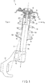
- a suspension coil spring according to a first embodiment will now be described with reference to FIGS. 1 and 2 .
- FIG. 1 shows a McPherson-strut-type suspension mechanism 11 provided in a vehicle body 10 (partly shown), which is an example of a suspension mechanism for vehicles.
- the suspension mechanism 11 comprises a coil spring (a compression coil spring) 12, an upper spring seat 13, a lower spring seat 14, a shock absorber 15 which functions as a strut, a mount member 16, a bracket 18, etc.
- the upper spring seat 13 is disposed on the upper side of the coil spring 12.
- the lower spring seat 14 is disposed on the lower side of the coil spring 12.
- An upper end of the shock absorber 15 is mounted on the vehicle body 10 by the mount member 16.
- a knuckle member 17 is fixed to the bracket 18.
- the shock absorber 15 includes a cylinder 15a and a rod 15b.
- An axis X S of the shock absorber 15 is inclined by angle ⁇ 1 with respect to a vertical line H extending vertically.
- the coil spring 12 is fitted onto the vehicle body 10 in such a state that it is compressed between the upper spring seat 13 and the lower spring seat 14 (i.e., a state in which a preload is applied).
- the coil spring 12 elastically supports the compressive load applied from above the vehicle 10.
- the coil spring 12 and the shock absorber 15 are extended and retracted between a full bump (the maximum compression state) and a full rebound (the maximum expansion state) in accordance with the magnitude of the load.
- a load applied from above the suspension mechanism 11 is supported by a wheel (a tire) via the knuckle member 17.
- a line of action of load input L1 forms an angle of ⁇ 2 to a vehicle-outer-side V out with respect to the axis X S of the shock absorber 15 in light of the relationship with a ground contact point of the tire.
- a lateral force is produced on the shock absorber 15 by this angle ⁇ 2. Since the lateral force becomes a cause of increasing friction of the shock absorber 15, it is desired to reduce the lateral force.
- FIG. 2 schematically illustrates the coil spring 12 arranged between the upper spring seat 13 and the lower spring seat 14.
- the coil spring 12 is mounted on the vehicle body 10 in an assembly state of being compressed between the upper spring seat 13 and the lower spring seat 14.
- a compressive load P is applied in a direction along a coil central axis X1
- the coil spring 12 is deformed in a direction of making the length of the coil spring 12 shorter than the free length (i.e., the length in a state where no load is applied).
- An example of the coil spring 12 is formed of an element (a wire 30) made of spring steel having a circular cross section.
- the wire 30 is formed in a helical shape.
- An example of the coil spring 12 is a cylindrical coil spring.
- various forms of compression coil springs such as a barrel-shaped coil spring, an hourglass coil spring, a tapered coil spring, a variable pitch coil spring, and the other shaped springs, can be adopted.
- a coating film for rust prevention is formed on the entire outer surface of the wire 30.
- the wire 30 of the coil spring 12 includes an upper portion 12a and a lower portion 12b.
- a coil body portion 12c wound helically at a pitch angle ⁇ is formed between the upper portion 12a and the lower portion 12b.
- the pitch angle ⁇ may be varied in the direction along the coil central axis X1.
- the pitch angle ⁇ may be substantially constant in the direction along the coil central axis X1.
- the coil central axis X1 passes through substantially the center of the coil body portion 12c.
- a winding end portion 31 of a positive pitch i.e., a positive pitch angle ⁇ 1 as shown in FIG. 2
- a terminal-point-strong-abutting-portion 35 is formed at a distal end (an upper end) of the winding end portion 31.
- the terminal-point-strong-abutting-portion 35 contacts the upper spring seat 13 at one point.
- the terminal-point-strong-abutting-portion 35 is in contact with the upper spring seat 13 at a position deviated away from the coil central axis X1 in a radial direction of the coil, more specifically, to a vehicle-inner-side V in , by a distance Y1.
- a wear-resistant force transmission portion 37 should preferably be provided.
- An end turn portion 40 is formed at the lower portion 12b of the coil spring 12.
- the number of turns of the end turn portion 40 is, for example, 0.5 or so.
- the end turn portion 40 is in contact with the lower spring seat 14 at a position deviated to the vehicle-outer-side V out with respect to the coil central axis X1.
- the end turn portion 40 includes a first portion 40a and a second portion 40b.
- the first portion 40a is always in contact with the spring seat 14 irrespective of the magnitude of the load P.
- the first portion 40a is a portion (non-effective portion) which does not function as a spring.
- the second portion 40b is separated from the spring seat 14 when the load P is small, and contacts the spring seat 14 when it is large.
- the coil spring 12 of the present embodiment is compressed between the terminal-point-strong-abutting-portion 35 and the end turn portion 40.
- the terminal-point-strong-abutting-portion 35 contacts the upper spring seat 13 at a position deviated to the vehicle-inner-side V in .
- the end turn portion 40 contacts the lower spring seat 14 at a position deviated to the vehicle-outer-side V out . Consequently, a force line position FLP is inclined in a direction along the line of action of force input L1 ( FIG. 1 ) at an angle of ⁇ 3 ( FIG. 2 ) with respect to the coil central axis X1.
- the force line position FLP is a center line of a repulsive load of the coil spring 12.
- the upper portion 12a contacts the upper spring seat 13 via the terminal-point-strong-abutting-portion 35.
- an end turn portion i.e., a portion which does not function as a spring
- almost the entire length of the coil spring 12 excluding the lower end turn portion 40 can be used as an effective portion of the spring.
- the mass can be reduced as compared to a conventional spring having an end turn portion on each of an upper end and a lower end.
- the wire when the compressive load P is increased, the wire can be brought into intimate contact for a certain length from the terminal-point-strong-abutting-portion 35. Also in this case, a load is substantially concentrated on the terminal-point-strong-abutting-portion 35.
- the winding end portion 31 of the positive pitch may have its pitch angle in the free state determined so that the spring seat 13, etc., can be protected in a state where a compressive load is applied to the coil spring 12.
- the pitch angle of the winding end portion 31 may be determined such that a region extending to 0.4 turns from the terminal-point-strong-abutting-portion 35 at a distal end of the wire 30, for example, contacts the spring seat 13.
- FIG. 3 shows a part of a coil spring 12 according to a second embodiment.
- a terminal-point-strong-abutting-portion 35 is formed at a distal end of the coil spring 12.
- a protection tip 50 as an example of a force transmission portion 37 is provided at the terminal-point-strong-abutting-portion 35.
- An example of the protection tip 50 is a wear-resistant tip formed of a material whose hardness is greater than that of a wire 30, and which is hard to wear (for example, cemented carbide, high-speed steel, or titanium alloy). This wear-resistant tip is arranged on a distal end of the wire 30.
- an elastomer such as urethane, rubber, or a polymeric material (resin) may be used for the material of the protection tip 50.
- a receiving portion 51 for a wear-resistant member, etc. is formed on a surface of a spring seat 13 where the protection tip 50 contacts.
- the receiving portion 51 may include a solid lubricant such as graphite. Since the other structures and functions have commonalities with those of the coil spring 12 of the first embodiment ( FIGS. 1 and 2 ), common reference numbers are assigned to parts in common with the first embodiment, and explanation of such parts is omitted.
- FIG. 4 shows a part of a coil spring 12 according to a third embodiment.
- a terminal-point-strong-abutting-portion 35 is formed at a distal end of the coil spring 12.
- a protection tip 50 is provided at the terminal-point-strong-abutting-portion 35.
- a recess 52 into which a spherical portion of the protection tip 50 is rotatably fitted may be formed on the receiving portion 51. Since the other structures and functions have commonalities with those of the coil spring 12 of the second embodiment, common reference numbers are assigned to parts in common with the second embodiment, and explanation of such parts is omitted.
- FIG. 5 is a side view showing a part of a coil spring 12 according to a fourth embodiment.
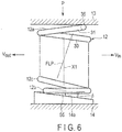
- FIG. 6 is a side view schematically showing a state in which the coil spring 12 shown in FIG. 5 is compressed between an upper spring seat 13 and a lower spring seat 14.
- a terminal-point-strong-abutting-portion 35 is provided at an upper end of the coil spring 12. The terminal-point-strong-abutting-portion 35 contacts the upper spring seat 13 at one point at a position deviated to a vehicle-inner-side V in with respect to a coil central axis X1.
- an end turn portion 55 is formed at the lower part of the coil spring 12.
- the end turn portion 55 has a negative pitch in the free state in which no load is applied.
- the end turn portion 55 of the negative pitch forms a negative angle (- ⁇ ) with respect to a line segment L2 orthogonal to the coil central axis X1.
- a portion excluding the end turn portion 55 has a positive pitch of pitch angle ⁇ 2.
- the end turn portion 55 on the lower side is supported at a position deviated to a vehicle-outer-side V out with respect to the coil central axis X1 by a supporting surface 14a of the lower spring seat 14, as shown in FIG. 6 .
- the supporting surface 14a of the lower spring seat 14 forms a positive inclination angle ⁇ .
- a force line position (a load axis) FLP can be inclined in a direction along a line of action of force input.
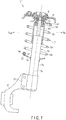
- FIG. 7 shows a suspension mechanism 11' according to a fifth embodiment.
- a terminal-point-strong-abutting-portion 35' is formed at a distal end of a winding end portion 60 on the lower part of a coil spring 12.
- the terminal-point-strong-abutting-portion 35' is in contact with a lower spring seat 14 at a position deviated to a vehicle-outer-side V out with respect to a coil central axis.
- An end turn portion 61 formed at the upper part of the coil spring 12 is in contact with an upper spring seat 13 at a position deviated to a vehicle-inner-side V in with respect to the coil central axis.
- a force line position (a load axis) can be inclined in a desired direction.
- the winding end portion 60 of a positive pitch may have its pitch angle in the free state determined so that the spring seat 14, etc., can be protected in a state where a compressive load is applied to the coil spring 12.
- the pitch angle of the winding end portion 60 may be determined such that a region extending to 0.4 turns from the terminal-point-strong-abutting-portion 35' at a lower end of a wire 30, for example, contacts the spring seat 14.
- a protection tip 50 and a receiving portion 51 shown in FIG. 3 or FIG. 4 may be provided at the terminal-point-strong-abutting-portion 35' .
- the lower part of the coil spring 12 is supported by the lower spring seat 14 via the terminal-point-strong-abutting-portion 35'. Accordingly, there is no need to provide an end turn portion on the lower part of the coil spring 12. According to this structure, it is possible to avoid the risk of the coil spring being damaged by hard foreign substances such as sand being trapped between the lower spring seat and the end turn portion. Since the other structures and functions have commonalities with those of the suspension mechanism 11 of the first embodiment ( FIGS. 1 and 2 ), common reference numbers are assigned to parts in common with the first embodiment, and explanation of such parts is omitted.
- a lateral force may be produced when the force line position (load axis) of the coil spring is inclined in a longitudinal direction of the vehicle.
- the lateral force may be canceled by arranging the terminal-point-strong-abutting-portion such that the force line position comes to a neutral position in the longitudinal direction.
- the present invention can be applied to a suspension mechanism of a vehicle other than cars. Also, the present invention can be applied to a coil spring of a suspension system other than the McPherson-strut-type suspension.
Landscapes
- Engineering & Computer Science (AREA)
- Mechanical Engineering (AREA)
- General Engineering & Computer Science (AREA)
- Springs (AREA)
- Vehicle Body Suspensions (AREA)
- Fluid-Damping Devices (AREA)
Abstract
Description
- The present invention relates to a suspension coil spring used in a suspension mechanism of a vehicle such as a car.
- The suspension mechanism of a vehicle such as a car comprises, for example, a suspension coil spring (hereinafter simply referred to as a coil spring), an upper spring seat, and a lower spring seat. The upper spring seat is disposed on the upper side of the coil spring. The lower spring seat is disposed on the lower side of the coil spring. The coil spring is compressed between the upper spring seat and the lower spring seat. The coil spring extends and retracts in accordance with the magnitude of a load.
- As an example of the suspension mechanism, a McPherson-strut-type suspension mechanism is known. The McPherson-strut-type suspension mechanism includes a coil spring, and a strut (a shock absorber). The coil spring is arranged between the upper spring seat and the lower spring seat. The strut is arranged inside the coil spring. Further, the coil spring extends and retracts in accordance with the magnitude of the load, and the strut also expands and contracts.
- In the McPherson-strut-type suspension mechanism, a central axis of the strut is displaced from a line of action of force input, which is obtained by connecting a ground contact point of a tire and a strut upper end, at an angle. Accordingly, it is known that a lateral force (a component of force which bends the strut) affects the strut, and this lateral force increases the sliding resistance of the strut. Patent Literatures 1 to 6 stated below disclose means for reducing the sliding resistance of the strut. In the well-known technology, a force line position of the coil spring is made parallel with the line of action of force input as much as possible, so that a lateral force produced on the strut is reduced. In the specification, the force line position may be referred to as a load axis.
-
- Patent Literature 1:
JP S58-32970 Y - Patent Literature 2:
EP 728602 A1 - Patent Literature 3:
JP 3515957 B - Patent Literature 4:
JP 4336203 B - Patent Literature 5:
JP 2013-173536 A - Patent Literature 6:
JP 2014-237431 A - In Patent Literature 1, a diameter of an end turn portion on a lower side of a coil spring is made smaller than a coil diameter of an effective portion, and the effective portion of the coil spring is arranged at a position offset to an outer side of a vehicle relative to a central axis of a strut. However, since the effective portion of the coil spring is offset to the outer side of the vehicle relative to the central axis of the strut, a space needed to arrange a suspension mechanism including the coil spring in a vehicle body becomes large.
- In Patent Literature 2, by bending a wire at places near an upper end and a lower end of a coil spring, projections which contact a lower spring seat and an upper spring seat, respectively, are formed on the end portions of the coil spring. A portion extending from each of the projections to the corresponding end of the wire is treated as a bent portion of a negative pitch (minus pitch). However, a portion from the negative pitch bent portion to a terminal of the wire is a portion which cannot function as a spring. Accordingly, the mass of the coil spring is increased because of the bent portion that is provided.
- In Patent Literature 3, a pitch angle of an effective portion of the coil spring is changed in accordance with the position of turns from an end for each turn of the wire. In this coil spring, by applying a load transversely (i.e., in a radial direction of a coil) in a usage state in which the coil spring is fitted to a suspension mechanism, an initial lateral force and a moment are produced. Further, in this state, by firmly holding both ends of the coil spring to an upper spring seat and a lower spring seat, respectively, the coil spring is compressed while maintaining this state. For this reason, with respect to the coil spring of Patent Literature 3, a preload needs to be applied transversely (the radial direction of the coil) when it is fitted to the suspension mechanism. Consequently, fitting of the coil spring to the suspension mechanism is not easy. Moreover, since an end turn portion which does not function as a spring exists in each of the both ends of the coil spring, the mass of the coil spring is increased by these end turn portions.
- In Patent Literature 4, a plurality of projections are formed on an end turn portion of a coil spring, and the wire is made to contact different projections according to a load applied to the coil spring. For example, in accordance with increase of the load, the projection on the farther side from an end of the wire contacts the spring seat. Accordingly, when a load applied to the coil spring is changed, a position of contact between the end turn portion and the spring seat is changed. Therefore, a force line position (load axis) is also changed.
- In a coil spring of Patent Literature 5, the coil spring is arranged offset to an outer side of a vehicle with respect to a central axis of a strut. Accordingly, a space needed for arranging a suspension mechanism including the coil spring in a vehicle body is increased.
- In a coil spring of Patent Literature 6, an end turn portion of a negative pitch (a reverse pitch), which does not function as a spring, is provided on each of the upper end and lower end of the coil spring. Accordingly, the mass of the coil spring is increased by the above negative pitch end turn portions.
- Depending on a vehicle, there may be a case where the force line position (load axis) of the coil spring is desired to be inclined in an aimed direction with respect to the coil central axis also in a suspension mechanism other than the McPherson-strut-type suspension mechanism.
- Accordingly, an object of the present invention is to provide a suspension coil spring whose force line position can be inclined in a desired direction with respect to the coil central axis, and whose weight can be reduced.
- One embodiment of the present invention relates to a suspension coil spring which is formed of a helically wound wire, and is compressed between an upper spring seat and a lower spring seat, in which the suspension coil spring includes: a winding end portion of a positive pitch at an upper portion of the wire, and a terminal-point-strong-abutting-portion, which contacts the upper spring seat at one point at a position deviated away from a coil central axis in a radial direction of the coil, at a distal end of the winding end portion. Further, the suspension coil spring includes an end turn portion, which contacts the lower spring seat at a position opposite to the terminal-point-strong-abutting-portion (for example, an outer side of a vehicle), at a lower portion of the wire.
- In this embodiment, the terminal-point-strong-abutting-portion may contact the upper spring seat at a position deviated to an inner side of the vehicle with respect to the coil central axis. In order to protect the spring seat, etc., the positive pitch winding end portion may have a pitch angle which allows a region extending to 0.4 turns from a distal end of the wire (the terminal-point-strong-abutting-portion) to contact the upper spring seat in a state in which a load is applied. Also, the terminal-point-strong-abutting-portion may be provided with a protection tip, and the upper spring seat with which the protection tip comes into contact may comprise a receiving portion such as a wear-resistant portion. Further, the embodiment may be structured such that the end turn portion is formed at a position deviated to the outer side of the vehicle, and that the end turn portion has a negative pitch when no compressive load is applied, and is deformed to have a positive pitch by being pressed by the lower spring seat when a load is applied.
- In another embodiment, a winding end portion of a positive pitch is provided at a lower portion of the wire, a terminal-point-strong-abutting-portion, which contacts the lower spring seat at one point at a position deviated to the outer side of the vehicle with respect to the coil central axis, is provided at a distal end of the winding end portion, and an end turn portion, which contacts the upper spring seat at a position deviated to the inner side of the vehicle, is provided at the upper portion of the wire.
- According to the present invention, it is possible to incline the force line position of the suspension coil spring in a direction desired for the suspension mechanism. For example, in the case of a McPherson-strut-type suspension mechanism, since the force line position of the coil spring can be made parallel with the line of action of load input, a lateral force and a bending moment produced on the strut can be reduced. Also, an end turn portion, which does not function as a spring, can be eliminated in at least one of the upper part and the lower part of the coil spring (i.e., the part provided with the terminal-point-strong-abutting-portion), whereby weight reduction is enabled.
-
-
FIG. 1 is a vertical cross-sectional view of a suspension mechanism according to a first embodiment. -
FIG. 2 is a perspective view of a coil spring of the suspension mechanism shown inFIG. 1 . -
FIG. 3 is a side view showing a terminal-point-strong-abutting-portion of a coil spring according to a second embodiment. -
FIG. 4 is a side view showing a terminal-point-strong-abutting-portion of a coil spring according to a third embodiment. -
FIG. 5 is a side view showing a lower part of a coil spring according to a fourth embodiment. -
FIG. 6 is a side view schematically showing a state in which the coil spring shown inFIG. 5 is compressed between an upper spring seat and a lower spring seat. -
FIG. 7 is a vertical cross-sectional view of a suspension mechanism according to a fifth embodiment. - A suspension coil spring according to a first embodiment will now be described with reference to
FIGS. 1 and2 . -
FIG. 1 shows a McPherson-strut-type suspension mechanism 11 provided in a vehicle body 10 (partly shown), which is an example of a suspension mechanism for vehicles. Thesuspension mechanism 11 comprises a coil spring (a compression coil spring) 12, anupper spring seat 13, alower spring seat 14, ashock absorber 15 which functions as a strut, amount member 16, abracket 18, etc. Theupper spring seat 13 is disposed on the upper side of thecoil spring 12. Thelower spring seat 14 is disposed on the lower side of thecoil spring 12. An upper end of theshock absorber 15 is mounted on thevehicle body 10 by themount member 16. Aknuckle member 17 is fixed to thebracket 18. Theshock absorber 15 includes acylinder 15a and arod 15b. An axis XS of theshock absorber 15 is inclined by angle θ1 with respect to a vertical line H extending vertically. - As shown in
FIG. 1 , thecoil spring 12 is fitted onto thevehicle body 10 in such a state that it is compressed between theupper spring seat 13 and the lower spring seat 14 (i.e., a state in which a preload is applied). Thecoil spring 12 elastically supports the compressive load applied from above thevehicle 10. Thecoil spring 12 and theshock absorber 15 are extended and retracted between a full bump (the maximum compression state) and a full rebound (the maximum expansion state) in accordance with the magnitude of the load. - A load applied from above the
suspension mechanism 11 is supported by a wheel (a tire) via theknuckle member 17. A line of action of load input L1 forms an angle of θ2 to a vehicle-outer-side Vout with respect to the axis XS of theshock absorber 15 in light of the relationship with a ground contact point of the tire. A lateral force is produced on theshock absorber 15 by this angle θ2. Since the lateral force becomes a cause of increasing friction of theshock absorber 15, it is desired to reduce the lateral force. -
FIG. 2 schematically illustrates thecoil spring 12 arranged between theupper spring seat 13 and thelower spring seat 14. Thecoil spring 12 is mounted on thevehicle body 10 in an assembly state of being compressed between theupper spring seat 13 and thelower spring seat 14. When a compressive load P is applied in a direction along a coil central axis X1, thecoil spring 12 is deformed in a direction of making the length of thecoil spring 12 shorter than the free length (i.e., the length in a state where no load is applied). - An example of the
coil spring 12 is formed of an element (a wire 30) made of spring steel having a circular cross section. Thewire 30 is formed in a helical shape. An example of thecoil spring 12 is a cylindrical coil spring. However, depending on the specification of a vehicle, various forms of compression coil springs, such as a barrel-shaped coil spring, an hourglass coil spring, a tapered coil spring, a variable pitch coil spring, and the other shaped springs, can be adopted. A coating film for rust prevention is formed on the entire outer surface of thewire 30. - The
wire 30 of thecoil spring 12 includes anupper portion 12a and alower portion 12b. Acoil body portion 12c wound helically at a pitch angle α is formed between theupper portion 12a and thelower portion 12b. The pitch angle α may be varied in the direction along the coil central axis X1. Alternatively, the pitch angle α may be substantially constant in the direction along the coil central axis X1. The coil central axis X1 passes through substantially the center of thecoil body portion 12c. - At the
upper portion 12a of thecoil spring 12, a windingend portion 31 of a positive pitch (i.e., a positive pitch angle α1 as shown inFIG. 2 ) is formed. A terminal-point-strong-abutting-portion 35 is formed at a distal end (an upper end) of the windingend portion 31. The terminal-point-strong-abutting-portion 35 contacts theupper spring seat 13 at one point. In other words, the terminal-point-strong-abutting-portion 35 is in contact with theupper spring seat 13 at a position deviated away from the coil central axis X1 in a radial direction of the coil, more specifically, to a vehicle-inner-side Vin, by a distance Y1. At a contact portion of theupper spring seat 13 and the terminal-point-strong-abutting-portion 35, a wear-resistant force transmission portion 37 (FIG. 1 ) should preferably be provided. - An
end turn portion 40 is formed at thelower portion 12b of thecoil spring 12. The number of turns of theend turn portion 40 is, for example, 0.5 or so. Theend turn portion 40 is in contact with thelower spring seat 14 at a position deviated to the vehicle-outer-side Vout with respect to the coil central axis X1. More specifically, theend turn portion 40 includes afirst portion 40a and asecond portion 40b. Thefirst portion 40a is always in contact with thespring seat 14 irrespective of the magnitude of the load P. Thus, thefirst portion 40a is a portion (non-effective portion) which does not function as a spring. Thesecond portion 40b is separated from thespring seat 14 when the load P is small, and contacts thespring seat 14 when it is large. - The
coil spring 12 of the present embodiment is compressed between the terminal-point-strong-abutting-portion 35 and theend turn portion 40. The terminal-point-strong-abutting-portion 35 contacts theupper spring seat 13 at a position deviated to the vehicle-inner-side Vin. Theend turn portion 40 contacts thelower spring seat 14 at a position deviated to the vehicle-outer-side Vout. Consequently, a force line position FLP is inclined in a direction along the line of action of force input L1 (FIG. 1 ) at an angle of θ3 (FIG. 2 ) with respect to the coil central axis X1. The force line position FLP is a center line of a repulsive load of thecoil spring 12. Since the force line position FLP is inclined in the direction along the line of action of force input L1, a component of force directed to the vehicle-outer-side Vout is produced at an upper end of thecoil spring 12. The component of force is effective in canceling a bending moment which is produced on theshock absorber 15. - Moreover, in the
coil spring 12 of the present embodiment, theupper portion 12a contacts theupper spring seat 13 via the terminal-point-strong-abutting-portion 35. For this reason, an end turn portion (i.e., a portion which does not function as a spring) is not required in theupper portion 12a of thecoil spring 12. More specifically, with respect to thecoil spring 12 of the present embodiment, almost the entire length of thecoil spring 12 excluding the lowerend turn portion 40 can be used as an effective portion of the spring. Thus, the mass can be reduced as compared to a conventional spring having an end turn portion on each of an upper end and a lower end. Note that when the compressive load P is increased, the wire can be brought into intimate contact for a certain length from the terminal-point-strong-abutting-portion 35. Also in this case, a load is substantially concentrated on the terminal-point-strong-abutting-portion 35. - The winding
end portion 31 of the positive pitch may have its pitch angle in the free state determined so that thespring seat 13, etc., can be protected in a state where a compressive load is applied to thecoil spring 12. The pitch angle of the windingend portion 31 may be determined such that a region extending to 0.4 turns from the terminal-point-strong-abutting-portion 35 at a distal end of thewire 30, for example, contacts thespring seat 13. -
FIG. 3 shows a part of acoil spring 12 according to a second embodiment. A terminal-point-strong-abutting-portion 35 is formed at a distal end of thecoil spring 12. Aprotection tip 50 as an example of aforce transmission portion 37 is provided at the terminal-point-strong-abutting-portion 35. An example of theprotection tip 50 is a wear-resistant tip formed of a material whose hardness is greater than that of awire 30, and which is hard to wear (for example, cemented carbide, high-speed steel, or titanium alloy). This wear-resistant tip is arranged on a distal end of thewire 30. Alternatively, an elastomer such as urethane, rubber, or a polymeric material (resin) may be used for the material of theprotection tip 50. - On a surface of a
spring seat 13 where theprotection tip 50 contacts, a receivingportion 51 for a wear-resistant member, etc., is formed. The receivingportion 51 may include a solid lubricant such as graphite. Since the other structures and functions have commonalities with those of thecoil spring 12 of the first embodiment (FIGS. 1 and2 ), common reference numbers are assigned to parts in common with the first embodiment, and explanation of such parts is omitted. -
FIG. 4 shows a part of acoil spring 12 according to a third embodiment. A terminal-point-strong-abutting-portion 35 is formed at a distal end of thecoil spring 12. Aprotection tip 50 is provided at the terminal-point-strong-abutting-portion 35. On a surface of aspring seat 13 where theprotection tip 50 contacts, a receivingportion 51 for a wear-resistant member, etc., is provided. Arecess 52 into which a spherical portion of theprotection tip 50 is rotatably fitted may be formed on the receivingportion 51. Since the other structures and functions have commonalities with those of thecoil spring 12 of the second embodiment, common reference numbers are assigned to parts in common with the second embodiment, and explanation of such parts is omitted. -
FIG. 5 is a side view showing a part of acoil spring 12 according to a fourth embodiment.FIG. 6 is a side view schematically showing a state in which thecoil spring 12 shown inFIG. 5 is compressed between anupper spring seat 13 and alower spring seat 14. A terminal-point-strong-abutting-portion 35 is provided at an upper end of thecoil spring 12. The terminal-point-strong-abutting-portion 35 contacts theupper spring seat 13 at one point at a position deviated to a vehicle-inner-side Vin with respect to a coil central axis X1. - As shown in
FIG. 5 , anend turn portion 55 is formed at the lower part of thecoil spring 12. Theend turn portion 55 has a negative pitch in the free state in which no load is applied. Theend turn portion 55 of the negative pitch forms a negative angle (-α) with respect to a line segment L2 orthogonal to the coil central axis X1. A portion excluding theend turn portion 55 has a positive pitch of pitch angle α2. Theend turn portion 55 on the lower side is supported at a position deviated to a vehicle-outer-side Vout with respect to the coil central axis X1 by a supportingsurface 14a of thelower spring seat 14, as shown inFIG. 6 . The supportingsurface 14a of thelower spring seat 14 forms a positive inclination angle β. When thecoil spring 12 is compressed between the spring seats 13 and 14 by a load P, theend turn portion 55 is elastically deformed in the positive pitch at a glance, in accordance with the inclination angle β of the supportingsurface 14a. Also with thecoil spring 12 as described above, a force line position (a load axis) FLP can be inclined in a direction along a line of action of force input. -
FIG. 7 shows a suspension mechanism 11' according to a fifth embodiment. At a distal end of a windingend portion 60 on the lower part of acoil spring 12, a terminal-point-strong-abutting-portion 35' is formed. The terminal-point-strong-abutting-portion 35' is in contact with alower spring seat 14 at a position deviated to a vehicle-outer-side Vout with respect to a coil central axis. Anend turn portion 61 formed at the upper part of thecoil spring 12 is in contact with anupper spring seat 13 at a position deviated to a vehicle-inner-side Vin with respect to the coil central axis. When the distal end of the lower windingend portion 60 is directed toward the outer side of the vehicle as in this embodiment, by forming the terminal-point-strong-abutting-portion 35' on the distal end of the windingend portion 60, a force line position (a load axis) can be inclined in a desired direction. - The winding
end portion 60 of a positive pitch may have its pitch angle in the free state determined so that thespring seat 14, etc., can be protected in a state where a compressive load is applied to thecoil spring 12. The pitch angle of the windingend portion 60 may be determined such that a region extending to 0.4 turns from the terminal-point-strong-abutting-portion 35' at a lower end of awire 30, for example, contacts thespring seat 14. Aprotection tip 50 and a receivingportion 51 shown inFIG. 3 or FIG. 4 may be provided at the terminal-point-strong-abutting-portion 35' . - According to the suspension mechanism 11' shown in
FIG. 7 , the lower part of thecoil spring 12 is supported by thelower spring seat 14 via the terminal-point-strong-abutting-portion 35'. Accordingly, there is no need to provide an end turn portion on the lower part of thecoil spring 12. According to this structure, it is possible to avoid the risk of the coil spring being damaged by hard foreign substances such as sand being trapped between the lower spring seat and the end turn portion. Since the other structures and functions have commonalities with those of thesuspension mechanism 11 of the first embodiment (FIGS. 1 and2 ), common reference numbers are assigned to parts in common with the first embodiment, and explanation of such parts is omitted. - Depending on the specification of a suspension, a lateral force may be produced when the force line position (load axis) of the coil spring is inclined in a longitudinal direction of the vehicle. When this lateral force affects the vehicle performance, the lateral force may be canceled by arranging the terminal-point-strong-abutting-portion such that the force line position comes to a neutral position in the longitudinal direction.
- Needless to say, in carrying out the present invention, not only the specific shape and arrangement of the coil spring, but also the position and shape of the terminal-point-strong-abutting-portion, and the shape, arrangement, etc., of the upper spring seat and the lower spring seat which constitute the suspension system may be modified variously. The present invention can be applied to a suspension mechanism of a vehicle other than cars. Also, the present invention can be applied to a coil spring of a suspension system other than the McPherson-strut-type suspension.
- 10···Vehicle body, 11,11'···Suspension mechanism, 12··· Coil spring (Suspension coil spring), 12a···Upper portion, 12b···Lower portion, 12c···Coil body portion, 13···Upper spring seat, 14···Lower spring seat, 15··· Shock absorber (strut), 30···Wire, 31···Positive pitch winding end portion, 35,35'···Terminal-point-strong-abutting-portion, 40···Lower end turn portion, 50··· Protection tip, 51····eceiving portion, 55···Negative pitch end turn portion, 60···Positive pitch winding end portion, 61··· Upper end turn portion, Vin···Inner side of vehicle, Vout···Outer side of vehicle, X1···Coil central axis, P···Compressive load, L1···Line of action of force input, FLP···Force line position (Load axis)
Claims (10)
- A suspension coil spring (12) which is formed of a helically wound wire (30), and is compressed between an upper spring seat (13) and a lower spring seat (14), the suspension coil spring (12) characterized by comprising:a winding end portion (31) of a positive pitch at an upper portion (12a) of the wire (30), and a terminal-point-strong-abutting-portion (35) at a distal end of the winding end portion (31), the terminal-point-strong-abutting-portion (35) contacting the upper spring seat (13) at one point at a position deviated away from a coil central axis (X1) in a radial direction of the coil; andan end turn portion (40) at a lower portion (12b) of the wire (30), the end turn portion (40) contacting the lower spring seat (14) at a position deviated to a side opposite to a side that the terminal-point-strong-abutting-portion (35) is provided.
- The suspension coil spring (12) of Claim 1, characterized in that the terminal-point-strong-abutting-portion (35) contacts the upper spring seat (13) at a position deviated to an inner side of a vehicle with respect to the coil central axis (X1).
- The suspension coil spring (12) of Claim 1, characterized in that the positive pitch winding end portion (31) has a pitch angle which allows a region extending to 0.4 turns from a distal end of the wire (30) to contact the upper spring seat (13) in a state where a load is applied.
- The suspension coil spring (12) of Claim 2, characterized in that the positive pitch winding end portion (31) has a pitch angle which allows a region extending to 0.4 turns from a distal end of the wire (30) to contact the upper spring seat (13) in a state where a load is applied.
- The suspension coil spring (12) of Claim 1, characterized in that a protection tip (50) is provided on the terminal-point-strong-abutting-portion (35), and the upper spring seat (13) with which the protection tip (50) comes into contact comprises a receiving portion (51).
- The suspension coil spring (12) of Claim 2, characterized in that a protection tip (50) is provided on the terminal-point-strong-abutting-portion (35), and the upper spring seat (13) with which the protection tip (50) comes into contact comprises a receiving portion (51).
- The suspension coil spring (12) of any one of Claims 2 to 6, characterized in that the end turn portion (40) is formed at a position deviated to an outer side of the vehicle, and that the end turn portion (40) has a negative pitch in a state where no compressive load is applied, and is deformed to have a positive pitch by being pressed by the lower spring seat (14) in a state where a load is applied.
- A suspension coil spring (12) which is formed of a helically wound wire (30), and is compressed between an upper spring seat (13) and a lower spring seat (14), the suspension coil spring (12) characterized by comprising:a winding end portion (60) of a positive pitch at a lower portion (12b) of the wire (30), and a terminal-point-strong-abutting-portion (35') at a distal end of the winding end portion (60), the terminal-point-strong-abutting-portion (35') contacting the lower spring seat (14) at one point at a position deviated to an outer side of a vehicle with respect to a coil central axis (X1); andan end turn portion (61) at an upper portion (12a) of the wire (30), the end turn portion (61) contacting the upper spring seat (13) at a position deviated to an inner side of the vehicle.
- The suspension coil spring (12) of Claim 8, characterized in that a protection tip (50) is provided on the terminal-point-strong-abutting-portion (35'), and the lower spring seat (14) with which the protection tip (50) comes into contact comprises a receiving portion (51).
- The suspension coil spring (12) of Claim 8, characterized in that the positive pitch winding end portion (60) has a pitch angle which allows a region extending to 0.4 turns from a lower end of the wire (30) to contact the lower spring seat (14) in a state where a load is applied.
Applications Claiming Priority (2)
| Application Number | Priority Date | Filing Date | Title |
|---|---|---|---|
| JP2015196036A JP6613095B2 (en) | 2015-10-01 | 2015-10-01 | Coil spring for suspension |
| PCT/JP2016/078908 WO2017057626A1 (en) | 2015-10-01 | 2016-09-29 | Coil spring for suspension |
Publications (2)
| Publication Number | Publication Date |
|---|---|
| EP3358212A1 true EP3358212A1 (en) | 2018-08-08 |
| EP3358212A4 EP3358212A4 (en) | 2019-05-08 |
Family
ID=58423589
Family Applications (1)
| Application Number | Title | Priority Date | Filing Date |
|---|---|---|---|
| EP16851797.7A Pending EP3358212A4 (en) | 2015-10-01 | 2016-09-29 | HELICAL SPRING FOR SUSPENSION |
Country Status (5)
| Country | Link |
|---|---|
| US (2) | US20180215227A1 (en) |
| EP (1) | EP3358212A4 (en) |
| JP (1) | JP6613095B2 (en) |
| CN (1) | CN108027003B (en) |
| WO (1) | WO2017057626A1 (en) |
Families Citing this family (3)
| Publication number | Priority date | Publication date | Assignee | Title |
|---|---|---|---|---|
| CN111566376B (en) * | 2018-03-07 | 2022-03-29 | 中央发条株式会社 | Spring |
| DE102018220235A1 (en) * | 2018-11-26 | 2020-05-28 | Ford Global Technologies, Llc | Independent wheel suspension for a motor vehicle |
| CN112158040A (en) * | 2020-10-13 | 2021-01-01 | 北京汽车集团越野车有限公司 | Elastic element installation assembly and automobile |
Family Cites Families (33)
| Publication number | Priority date | Publication date | Assignee | Title |
|---|---|---|---|---|
| JPS5832970Y2 (en) * | 1978-04-27 | 1983-07-22 | 三菱自動車工業株式会社 | strut suspension |
| DE3136954A1 (en) * | 1981-09-17 | 1983-03-31 | Audi Nsu Auto Union Ag, 7107 Neckarsulm | Device for resetting the steered wheels of a motor vehicle |
| FR2540586B1 (en) * | 1983-02-08 | 1985-06-07 | Ressorts Ind | NEW ASSOCIATION OF A SPRING AND AT LEAST ONE OF ITS CUPS, SAID ASSOCIATION IN PARTICULAR USED TO REALIZE A MAC PHERSON SUSPENSION LEG |
| DE3467868D1 (en) * | 1983-09-13 | 1988-01-14 | Ahle Gmbh & Co Geb | Arrangement for connecting a helical spring to a motor vehicle wheel suspension arm |
| JPH0126915Y2 (en) * | 1985-07-09 | 1989-08-11 | ||
| JPS6271423U (en) * | 1985-10-25 | 1987-05-07 | ||
| JP2778735B2 (en) * | 1989-03-31 | 1998-07-23 | 日本発条株式会社 | Coil spring device |
| DE4110471A1 (en) * | 1990-04-14 | 1991-10-17 | Volkswagen Ag | SHOCK ABSORBER |
| FR2730673B1 (en) * | 1995-02-17 | 1997-05-09 | Allevard Sa | MAC PHERSON TYPE SUSPENSION DEVICE FOR VEHICLE |
| EP0780250B1 (en) * | 1995-12-19 | 2003-04-02 | COMPAGNIE GENERALE DES ETABLISSEMENTS MICHELIN-MICHELIN & CIE | Fine adjustment of a MacPherson suspension strut: means for adjusting on the strut and measuring bench |
| JP3936427B2 (en) * | 1997-04-08 | 2007-06-27 | Nskワーナー株式会社 | Compression coil spring |
| BR9906649A (en) | 1998-07-27 | 2000-08-29 | Nhk Spring Co Ltd | Wheel and spring suspension system for the same |
| JP3960710B2 (en) * | 1998-07-31 | 2007-08-15 | 中央発條株式会社 | Suspension coil spring for automobile |
| US6247688B1 (en) * | 1998-08-10 | 2001-06-19 | Michelin Avs | Vehicle wheel suspension device |
| JP2002234324A (en) * | 2001-02-08 | 2002-08-20 | Chuo Spring Co Ltd | Automotive suspension coil spring and strut-type suspension device provided with the suspension coil spring |
| EP2233329B1 (en) | 2001-04-13 | 2015-08-26 | Mitsubishi Steel MFG. CO., LTD. | Suspension coil spring |
| JP3801947B2 (en) * | 2001-05-29 | 2006-07-26 | 三菱製鋼株式会社 | Spring seat |
| WO2003046406A1 (en) * | 2001-11-27 | 2003-06-05 | Nhk Spring Co., Ltd | Compression coil spring device having discontinuous support structure |
| KR20040080470A (en) * | 2003-03-11 | 2004-09-20 | 엘지전자 주식회사 | Mounting structure for control box of Airconditioner |
| JP2007333128A (en) * | 2006-06-16 | 2007-12-27 | Swcc Showa Device Technology Co Ltd | Coil spring and vibration isolator using the same |
| DE102007038072B4 (en) * | 2006-12-18 | 2022-10-13 | Muhr Und Bender Kg | suspension |
| EP1935678A3 (en) * | 2006-12-18 | 2010-04-14 | Muhr und Bender KG | Wheel suspension |
| DE102007038070A1 (en) * | 2007-02-15 | 2008-08-28 | Muhr Und Bender Kg | Wheel suspension i.e. McPherson wheel suspension, has helical compression spring provided between upper spring support and lower spring seat, and covering partially provided between lower spring end of compression spring and spring seat |
| CN201496455U (en) * | 2009-07-29 | 2010-06-02 | 杭州钱江弹簧有限公司 | Suspension spring |
| JP2012001162A (en) * | 2010-06-18 | 2012-01-05 | Chuo Spring Co Ltd | Suspension device |
| US9399381B2 (en) * | 2012-06-01 | 2016-07-26 | Toyota Jidosha Kabushiki Kaisha | Vehicle suspension device |
| JP6007097B2 (en) * | 2012-12-20 | 2016-10-12 | 日本発條株式会社 | Suspension spring device and suspension coil spring |
| FR3003803B1 (en) | 2013-04-02 | 2016-12-30 | Skf Ab | SUSPENSION ROCKING DEVICE AND SUSPENSION LEG EQUIPPED WITH SUCH A ROCKET |
| BR112015025554A2 (en) * | 2013-04-10 | 2017-07-18 | Tenneco Automotive Operating Co Inc | suspension leveling system |
| JP5873891B2 (en) * | 2013-05-10 | 2016-03-01 | 三菱製鋼株式会社 | Suspension coil spring and strut suspension system |
| JP6307323B2 (en) * | 2014-03-28 | 2018-04-04 | 日本発條株式会社 | Coil spring for suspension |
| MX367553B (en) * | 2014-05-28 | 2019-08-27 | Nhk Spring Co Ltd | Suspension spring device and suspension coil spring. |
| JP5981958B2 (en) * | 2014-05-28 | 2016-08-31 | 三菱製鋼株式会社 | Suspension coil spring and strut suspension system |
-
2015
- 2015-10-01 JP JP2015196036A patent/JP6613095B2/en active Active
-
2016
- 2016-09-29 WO PCT/JP2016/078908 patent/WO2017057626A1/en not_active Ceased
- 2016-09-29 CN CN201680054728.XA patent/CN108027003B/en active Active
- 2016-09-29 EP EP16851797.7A patent/EP3358212A4/en active Pending
-
2018
- 2018-03-27 US US15/937,468 patent/US20180215227A1/en not_active Abandoned
-
2020
- 2020-02-25 US US16/799,916 patent/US10899188B2/en active Active
Also Published As
| Publication number | Publication date |
|---|---|
| US20180215227A1 (en) | 2018-08-02 |
| EP3358212A4 (en) | 2019-05-08 |
| US20200189343A1 (en) | 2020-06-18 |
| WO2017057626A1 (en) | 2017-04-06 |
| CN108027003B (en) | 2019-12-31 |
| JP2017067237A (en) | 2017-04-06 |
| JP6613095B2 (en) | 2019-11-27 |
| US10899188B2 (en) | 2021-01-26 |
| CN108027003A (en) | 2018-05-11 |
Similar Documents
| Publication | Publication Date | Title |
|---|---|---|
| EP3034903B1 (en) | Coiled spring for suspension device | |
| US10899188B2 (en) | Coil spring for suspension | |
| CN104936803A (en) | Suspension device and compression coil spring for suspension device | |
| CA2890871C (en) | Strut-type suspension and compression coil spring for suspension | |
| EP3260729B1 (en) | Lower-side spring-receiving member | |
| EP3127727B1 (en) | Suspension coil spring | |
| JP6568882B2 (en) | Suspension device | |
| EP4116117A1 (en) | An improved coil spring for vehicle suspension system | |
| JP2018135935A (en) | Bush including inter-ring |
Legal Events
| Date | Code | Title | Description |
|---|---|---|---|
| STAA | Information on the status of an ep patent application or granted ep patent |
Free format text: STATUS: THE INTERNATIONAL PUBLICATION HAS BEEN MADE |
|
| PUAI | Public reference made under article 153(3) epc to a published international application that has entered the european phase |
Free format text: ORIGINAL CODE: 0009012 |
|
| STAA | Information on the status of an ep patent application or granted ep patent |
Free format text: STATUS: REQUEST FOR EXAMINATION WAS MADE |
|
| 17P | Request for examination filed |
Effective date: 20180327 |
|
| AK | Designated contracting states |
Kind code of ref document: A1 Designated state(s): AL AT BE BG CH CY CZ DE DK EE ES FI FR GB GR HR HU IE IS IT LI LT LU LV MC MK MT NL NO PL PT RO RS SE SI SK SM TR |
|
| AX | Request for extension of the european patent |
Extension state: BA ME |
|
| DAV | Request for validation of the european patent (deleted) | ||
| DAX | Request for extension of the european patent (deleted) | ||
| A4 | Supplementary search report drawn up and despatched |
Effective date: 20190405 |
|
| RIC1 | Information provided on ipc code assigned before grant |
Ipc: F16F 1/12 20060101AFI20190401BHEP Ipc: B60G 15/06 20060101ALI20190401BHEP Ipc: F16F 1/06 20060101ALI20190401BHEP Ipc: B60G 11/16 20060101ALI20190401BHEP |
|
| STAA | Information on the status of an ep patent application or granted ep patent |
Free format text: STATUS: EXAMINATION IS IN PROGRESS |
|
| 17Q | First examination report despatched |
Effective date: 20210322 |