EP3358203A1 - Clamping band attachment method and clamping band attachment apparatus - Google Patents
Clamping band attachment method and clamping band attachment apparatus Download PDFInfo
- Publication number
- EP3358203A1 EP3358203A1 EP16851028.7A EP16851028A EP3358203A1 EP 3358203 A1 EP3358203 A1 EP 3358203A1 EP 16851028 A EP16851028 A EP 16851028A EP 3358203 A1 EP3358203 A1 EP 3358203A1
- Authority
- EP
- European Patent Office
- Prior art keywords
- pair
- claw members
- ring portion
- end engagement
- portions
- Prior art date
- Legal status (The legal status is an assumption and is not a legal conclusion. Google has not performed a legal analysis and makes no representation as to the accuracy of the status listed.)
- Withdrawn
Links
Images




Classifications
-
- B—PERFORMING OPERATIONS; TRANSPORTING
- B23—MACHINE TOOLS; METAL-WORKING NOT OTHERWISE PROVIDED FOR
- B23P—METAL-WORKING NOT OTHERWISE PROVIDED FOR; COMBINED OPERATIONS; UNIVERSAL MACHINE TOOLS
- B23P19/00—Machines for simply fitting together or separating metal parts or objects, or metal and non-metal parts, whether or not involving some deformation; Tools or devices therefor so far as not provided for in other classes
- B23P19/04—Machines for simply fitting together or separating metal parts or objects, or metal and non-metal parts, whether or not involving some deformation; Tools or devices therefor so far as not provided for in other classes for assembling or disassembling parts
- B23P19/08—Machines for placing washers, circlips, or the like on bolts or other members
- B23P19/084—Machines for placing washers, circlips, or the like on bolts or other members for placing resilient or flexible rings, e.g. O-rings, circlips
-
- B—PERFORMING OPERATIONS; TRANSPORTING
- B23—MACHINE TOOLS; METAL-WORKING NOT OTHERWISE PROVIDED FOR
- B23P—METAL-WORKING NOT OTHERWISE PROVIDED FOR; COMBINED OPERATIONS; UNIVERSAL MACHINE TOOLS
- B23P19/00—Machines for simply fitting together or separating metal parts or objects, or metal and non-metal parts, whether or not involving some deformation; Tools or devices therefor so far as not provided for in other classes
- B23P19/04—Machines for simply fitting together or separating metal parts or objects, or metal and non-metal parts, whether or not involving some deformation; Tools or devices therefor so far as not provided for in other classes for assembling or disassembling parts
- B23P19/08—Machines for placing washers, circlips, or the like on bolts or other members
- B23P19/084—Machines for placing washers, circlips, or the like on bolts or other members for placing resilient or flexible rings, e.g. O-rings, circlips
- B23P19/086—Non-metallic protective bellows
-
- F—MECHANICAL ENGINEERING; LIGHTING; HEATING; WEAPONS; BLASTING
- F16—ENGINEERING ELEMENTS AND UNITS; GENERAL MEASURES FOR PRODUCING AND MAINTAINING EFFECTIVE FUNCTIONING OF MACHINES OR INSTALLATIONS; THERMAL INSULATION IN GENERAL
- F16B—DEVICES FOR FASTENING OR SECURING CONSTRUCTIONAL ELEMENTS OR MACHINE PARTS TOGETHER, e.g. NAILS, BOLTS, CIRCLIPS, CLAMPS, CLIPS OR WEDGES; JOINTS OR JOINTING
- F16B2/00—Friction-grip releasable fastenings
- F16B2/02—Clamps, i.e. with gripping action effected by positive means other than the inherent resistance to deformation of the material of the fastening
- F16B2/06—Clamps, i.e. with gripping action effected by positive means other than the inherent resistance to deformation of the material of the fastening external, i.e. with contracting action
- F16B2/08—Clamps, i.e. with gripping action effected by positive means other than the inherent resistance to deformation of the material of the fastening external, i.e. with contracting action using bands
-
- F—MECHANICAL ENGINEERING; LIGHTING; HEATING; WEAPONS; BLASTING
- F16—ENGINEERING ELEMENTS AND UNITS; GENERAL MEASURES FOR PRODUCING AND MAINTAINING EFFECTIVE FUNCTIONING OF MACHINES OR INSTALLATIONS; THERMAL INSULATION IN GENERAL
- F16D—COUPLINGS FOR TRANSMITTING ROTATION; CLUTCHES; BRAKES
- F16D3/00—Yielding couplings, i.e. with means permitting movement between the connected parts during the drive
- F16D3/84—Shrouds, e.g. casings, covers; Sealing means specially adapted therefor
-
- B—PERFORMING OPERATIONS; TRANSPORTING
- B23—MACHINE TOOLS; METAL-WORKING NOT OTHERWISE PROVIDED FOR
- B23P—METAL-WORKING NOT OTHERWISE PROVIDED FOR; COMBINED OPERATIONS; UNIVERSAL MACHINE TOOLS
- B23P2700/00—Indexing scheme relating to the articles being treated, e.g. manufactured, repaired, assembled, connected or other operations covered in the subgroups
- B23P2700/11—Joints, e.g. ball joints, universal joints
-
- F—MECHANICAL ENGINEERING; LIGHTING; HEATING; WEAPONS; BLASTING
- F16—ENGINEERING ELEMENTS AND UNITS; GENERAL MEASURES FOR PRODUCING AND MAINTAINING EFFECTIVE FUNCTIONING OF MACHINES OR INSTALLATIONS; THERMAL INSULATION IN GENERAL
- F16D—COUPLINGS FOR TRANSMITTING ROTATION; CLUTCHES; BRAKES
- F16D3/00—Yielding couplings, i.e. with means permitting movement between the connected parts during the drive
- F16D3/84—Shrouds, e.g. casings, covers; Sealing means specially adapted therefor
- F16D3/843—Shrouds, e.g. casings, covers; Sealing means specially adapted therefor enclosed covers
- F16D3/845—Shrouds, e.g. casings, covers; Sealing means specially adapted therefor enclosed covers allowing relative movement of joint parts due to the flexing of the cover
Definitions
- the present invention relates to a clamping band attachment method and a clamping band attachment apparatus.
- a boot is attached to a constant velocity universal joint used for transmission of power in an automobile or various industrial machines, in order to prevent foreign matter such as dust from entering the inside of the joint and to prevent leakage of grease sealed in the joint.
- a silicone material a silicone material, a CR material (chloroprene), a VAMAC material (ethylene-acrylic rubber), a CM material (chlorinated polyethylene), and the like are known.
- the boot for the constant velocity universal joint is mounted and fixed to the constant velocity universal joint by using a fastening band.
- a fastening band is a low-profile band described in Patent Literature 1 or the like. This band is configured by rolling a belt-shaped member 1 as illustrated in Fig. 17 into a ring shape as illustrated in Figs. 18A, 18B, and 18C . The band is externally fitted to and mounted on a mounting portion of the boot.
- a protrusion portion 2 protruding toward a front surface side, a claw portion 3 located close to the protrusion portion 2, and protrusion portions 4, 5 located close to the claw portion 3 and protruding toward the front surface side are provided.
- an engaging hole 6 having a rectangular shape and an elongated hole 7 located close to the engaging hole 6 are provided.
- the elongated hole 7 is provided with a protrusion portion 8 that protrudes toward the front surface side on the side opposite to the engaging hole 6.
- the band is rounded into a ring shape so that the protrusion portion 2 fits in the elongated hole 7 as illustrated in Fig. 18A . That is, a ring portion 9 is formed, and the ring portion 9 is externally fitted to a band mounting portion of the boot in a loosely fitted state. In this case, the protrusion portion 2 is placed on a side closer to the engaging hole 6 in the elongated hole 7.
- the protrusion portion 8 and the protrusion portion 2 are sandwiched by a tool 10 (see Figs. 19A and 19B ) to be described later, and the tool 10 is operated to bring the protrusion portion 2 and the protrusion portion 8 relatively closer to each other as illustrated in Fig. 18B .
- the diameter of the ring portion 9 gradually decreases.
- the protrusion portion 5 is engaged with the engaging hole 6, and the protrusion portion 4 is engaged with the side closer to the engaging hole 6 of the elongated hole 7.
- this band clamps the band mounting portion of the boot. Therefore, the boot can be fixed to an outer joint member of the constant velocity universal joint or a shaft fitted into an inner joint member of the constant velocity universal joint.
- Patent Literature 1 JP 2001-219960 A
- the tool 10 includes a pair of claw members 13, 13.
- the claw members 13, 13 swing about a pivotal supporting shaft and swing along an arc (locus) 15.
- An object of the present invention is to provide a clamping band attachment method and a clamping band attachment apparatus capable of reducing the diameter of a fastening band stably even by a beginner without being skilled and of fixing a boot to a boot mounting portion.
- the clamping band attachment method includes: rounding a belt-shaped member in a ring shape and forming a ring portion which is externally fitted to a band mounting portion of a boot; the ring portion being formed with a pair of protrusion portions separated at a predetermined pitch along a circumferential direction; and bringing the pair of protrusion portions close to each other in the circumferential direction so as to reduce a diameter of the ring portion.
- a sliding body slides with contact of the front end engagement portion to one of the ring portion and the pair of protrusion portions of the ring portion so as to follow a radial and circumferential displacement of the pair of protrusion portions accompanying a diameter reduction of the ring portion while the front end engagement portions of the pair of claw members are swung in a direction approaching each other about a pivotal supporting portion.
- the sliding bodies of the pair of claw members can be set so as to slide independently. By setting the sliding bodies in this manner, it is possible for the sliding bodies to flexibly follow the outer diameter of the ring portion without being affected by variation in the shape of the ring portion.
- a clamping band attachment apparatus is a clamping band attachment apparatus which rounds a belt-shaped member in a ring shape and forms a ring portion externally fitted to a band mounting portion of a boot, the ring portion being formed with a pair of protrusion portions separated at a predetermined pitch along a circumferential direction, and brings the pair of protrusion portions close to each other in the circumferential direction so as to reduce a diameter of the ring portion.
- the clamping band attachment apparatus includes: clamping means which has a pair of claw members that swing in a direction in which front end engagement portions of the pair of claw members approach and separate from each other about a pivotal supporting portion; reciprocating means which reciprocates the pair of claw members of the clamping means in a direction approaching and separating from the band mounting portion of the boot; and swinging means which swings the pair of claw members of the clamping means in a direction approaching and separating from each other.
- the pair of claw member includes a claw member main body, and a sliding body formed with each of the front end engagement portions.
- the sliding body formed with each of the front end engagement portions is slidably attached to the claw member main body as to follow a radial and circumferential displacement of each of the pair of protrusion portions accompanying a diameter reduction of the ring portion while the front end engagement portions of the pair of claw members are swung in the direction approaching each other about the pivotal supporting portion.
- the claw members can approach and separate from the band mounting portion of the boot via the reciprocating means.
- the claw members can be swung in the direction approaching and separating from each other via the swinging means. Therefore, it is possible to bring the pair of claw members into an open state where the pair of claw members is separated from each other, and to bring the pair of claw members close to the band mounting portion. Then, the pair of protrusion portions can be clamped by the front end engagement portions of the pair of claw members. In this state, if the claw members are brought close to each other, the diameter of the ring portion can be reduced.
- the protrusion portions are displaced in the radial and circumferential directions, accompanying the diameter reduction of the ring portion.
- the sliding body having the front end engagement portion it is possible for the sliding body having the front end engagement portion to slide so as to follow the displacements of the ring portion.
- the sliding body is attached to the claw member main body via an elastic member that elastically presses the sliding body toward a front end side to bring the sliding body in a forward state in a free state, and allows the sliding body to move backward upon contact with one of the ring portion and each of the protrusion portions of the ring portion in a state where the front end engagement portions are brought close to each other.
- the swinging means may include a wedge member which expands and reduces the interval between the front end engagement portions of the pair of claw members by reciprocating in the axial direction between the pair of claw members on the rear end side with respect to the pivotal supporting shaft.
- the present invention it is possible to reduce the diameter of the ring portion without using a control mechanism or the like and without performing manual work by a worker for the radial and circumferential displacement of the protrusion portions, and to stably mount the boot on the boot mounting portion. Therefore, work efficiency can be improved and cost can be reduced.
- Fig. 16 illustrates a drive shaft on which a fastening band is mounted using a band attachment apparatus of the present invention.
- the drive shaft includes a fixed-type constant velocity universal joint 21, a sliding-type constant velocity universal joint 22, and a shaft 23 connecting the constant velocity universal joints.
- a Birfield constant velocity universal joint is used as the fixed-type constant velocity universal joint 21
- a tripod constant velocity universal joint is used as the sliding-type constant velocity universal joint 22.
- the fixed-type constant velocity universal joint 21 includes: an outer joint member 26 having a plurality of tracks 24 extending axially and formed on an inner spherical surface 25; an inner joint member 29 having a plurality of tracks 27 extending axially and formed on an outer spherical surface 28; a plurality of balls 30 interposed between the tracks 24 of the outer joint member 26 and the tracks 27 of the inner joint member 29 to transmit torque; and a cage 31 interposed between the inner spherical surface 25 of the outer joint member 26 and the outer spherical surface 28 of the inner joint member 29 to hold the balls.
- the sliding-type constant velocity universal joint 22 includes: an outer joint member 33 which has three grooves 32 extending in the axial direction on the inner periphery thereof, and roller-ring guide surfaces 32a facing each other and formed on an inner side wall of each groove 32; a tripod member 35 which includes three leg shafts 34 protruding in the radial direction and serving as an inner joint member; and a roller ring 36 which is rotatably supported by the leg shaft 34, is rotatably inserted into the groove 32 of the outer joint member 33 so as to freely roll, and serves as a torque transmission member.
- the roller ring 36 is externally fitted to the outer circumferential surface of the leg shaft 34 via a plurality of rollers 37 arranged along the circumferential direction.
- the tripod member 35 includes a boss portion 38 and the leg shafts 34 extending radially from the boss portion 38.
- Male splines 23a, 23b are formed at both end portions of the shaft 23.
- the male spline 23a on one side is fitted into the inner joint member 29 of the fixed-type constant velocity universal joint 21, and the male spline 23b on the other side is fitted into the tripod member 35 of the sliding-type constant velocity universal joint 22.
- a female spline 40 is formed in an axial hole of the inner joint member 29.
- the male spline 23a on the one side of the shaft 23 is fitted into the axial hole of the inner joint member 29 and meshes with the female spline 40.
- the male spline 23b on the other side of the shaft 23 is fitted into an axial hole of the boss portion 38 of the tripod member 35 and meshes with a female spline 40 of the axial hole.
- a boot 45 (45A) for sealing an opening of the outer joint member 26 is attached to the fixed-type constant velocity universal joint 21.
- a boot 45 (45B) for sealing an opening of the outer joint member 33 is attached to the sliding-type constant velocity universal joint 22.
- Each of the boots 45A, 45B includes a large-diameter band mounting portion 46a, a small-diameter band mounting portion 46b, and a bellows portion 46c constituting a bent portion connecting the large-diameter band mounting portion 46a and the small-diameter band mounting portion 46b.
- the large-diameter band mounting portions 46a of the boots 45A, 45B are clamped and fixed by fastening bands 50 (50A, 50B) at boot mounting portions 47, 47 formed on the outer circumferential surfaces on the opening sides of the outer joint members 26, 33, respectively.
- the small-diameter band mounting portions 46b of the boots 45A, 45B are clamped and fixed by fastening bands 50 (50A, 50B) at predetermined sections (boot mounting portions 47, 47) of the shaft 23.
- the fastening band 50 is formed of a belt-shaped member 51 as illustrated in Figs. 12 to 14 .
- the belt-shaped member 51 made of metal has a narrow portion 52 formed on one end side thereof, and a protrusion portion 53 provided near the narrow portion 52 and protruding toward a front surface 51a side.
- a protrusion portion 54 and engaging pieces 55a, 55b projecting toward the front surface 51a side are provided on a protrusion portion 53 side.
- an elongated hole 56 having a rectangular shape and an engaging hole 57 having a square shape are provided on the other end side of the belt-shaped member 51.
- a protrusion portion 58 protruding toward the front surface 51a side is provided on the side opposite to the engaging hole 57 of the elongated hole 56 having a rectangular shape.
- the protrusion portion 53 and the protrusion portion 58 are constituted of triangular bodies configured of a pair of inclined pieces 53a, 53a, 58a, 58a, respectively.
- the protrusion portion 54 is configured of an upright piece 54a erected and protruding from the front surface 51a of the belt-shaped member 51, and a parallel piece 54b extending substantially parallel to the belt-shaped member 51 from the upright piece 54a.
- each of the engaging pieces 55a, 55b is formed in a hook shape.
- aluminum, stainless steel, or the like can be used as the material of the fastening band 50; however, the material is not limited to them.
- a ring portion 60 is formed by rounding the fastening band 50 into a ring shape.
- the fastening band 50 is rounded such that the one end side where the protrusion portions 53, 54 and the engaging pieces 55a, 55b are provided is located at an inner side than the other end side where the elongated hole 56 (see Fig. 12 ) and the engaging hole 57 (see Fig. 12 ) are provided.
- the protrusion portion 53 on the one end side is fitted into the elongated hole 56 from the inner side. In this case, the protrusion portion 53 is positioned closer to the engaging hole 57 in the elongated hole 56.
- the protrusion portion 53 and the protrusion portion 58 are brought close to each other by using a band attachment apparatus for the constant velocity universal joint according to the present invention.
- the ring portion 60 configured of the belt-shaped member 51 is reduced in diameter. That is, since the protrusion portion 53 is provided on the one end side and the protrusion portion 58 is provided on the other end side, the ring portion 60 is reduced in diameter by bringing the protrusion portion 53 and the protrusion portion 58 close to each other.
- the engaging piece 55a is engaged with the elongated hole 56, and the engaging piece 55b is engaged with the engaging hole 57. That is, the pair of engaging pieces 55a, 55b clamps a partition portion 61 between the elongated hole 56 and the engaging hole 57. As a result, this diameter-reduced state can be maintained.
- this clamping band attachment apparatus includes: a pair of clamping means 73A, 73B each having a pair of claw members 71, 72; a pair of reciprocating means 74 (74A, 74B) which reciprocate the pair of claw members 71, 72 of each of the clamping means 73A, 73B in a direction approaching and separating from the band mounting portion (the large-diameter portion 46a or the small-diameter portion 46b) of the boot 45; and swinging means 75 (75A, 75B) which swing the claw members 71, 72 of the clamping means 73 (73A, 73B) in a direction approaching and separating from each other.
- each of the claw members 71, 72 swing in directions of arrows A, B about a pivotal supporting portion (pivotal supporting shaft) 80. That is, each of the claw members 71, 72 has a claw member main body 76 and a sliding body 77 in which a front end engagement portion 71a or 72a is formed.
- the claw member 71 on one side has a protruding rib 78 for pivotal support which is provided substantially at the center in the longitudinal direction on the inner surface (surface facing the claw member 72 on the other side) of the claw member main body 76.
- the claw member 72 on the other side has a pair of protruding ribs 79, 79 which sandwich the protruding rib 78 and are provided on the inner surface (surface facing the claw member 71 on the one side) of the claw member main body 76.
- Through holes are provided in the protruding rib 78 and the protruding ribs 79, 79, and the pivotal supporting shaft 80 is fitted into the through holes.
- the claw members 71, 72 can swing in the directions of arrows A, B about the pivotal supporting portion (pivotal supporting shaft) 80.
- the sliding body 77 has a first block body 81 constituting the front end engagement portion 71a (72a), and a second block body 82 integrated with the first block body 81.
- the second block body 82 has a cutout portion 83 in which the first block body 81 is fitted, and a projecting portion 84 fitted in a recessed portion 85 provided in the claw member main body 76.
- the claw member main body 76 is provided with a cutout portion 76a in which the sliding body 77 is fitted, and the recessed portion 85 is formed in the cutout portion 76a.
- the first block body 81 and the second block body 82 are integrated via a bolt member, not illustrated. That is, a screw hole 86 is provided in the first block body 81, and a through hole 87 in the second block body 82 through which the bolt member is inserted is provided.
- the claw member main body 76 is provided with a through hole 88 corresponding to the through hole 87 of the second block body 82. Therefore, by inserting the bolt member (not illustrated), through the through hole 88 into the through hole 87 and screwing the bolt member in the screw hole 86, the first block body 81 and the second block body 82 are integrated.
- the sliding body 77 can reciprocate along the axial direction of the claw member main body 76 in a state of being fitted in the cutout portion 76a of the claw member main body 76.
- a pin member 89 is provided on a claw member main body 76 side, and an elongated hole 90 for guide is provided in the second block body 82 of the sliding body 77. The pin member 89 is fitted into the elongated hole 90 to regulate sliding length.
- a recessed portion 84a is provided in the projecting portion 84 of the second block body 82.
- a recessed portion 85c is provided in a bottom surface 85b of the recessed portion 85 of the cutout portion 76a of the claw member main body 76.
- An elastic member 91 configured of a coil spring is fitted in the recessed portion 84a and the recessed portion 85c. For this reason, normally (in a free state), due to elastic force of the elastic member 91, the sliding body 77 is pressed in a direction of arrow C toward a front end side, and the pin member 89 is positioned at the upper end of the elongated hole 90. Sliding of the sliding body 77 further in the direction of arrow C is restricted.
- the sliding body 77 slides in the direction of arrow D as illustrated in Fig. 8 .
- the sliding body 77 slides in the direction of arrow D either until an end surface 84b of the projecting portion 84 of the second block body 82 abuts against the bottom surface 85b of the recessed portion 85 of the cutout portion 76a of the claw member main body 76, or until the pin member 89 is positioned at the lower edge of the elongated hole 90.
- the swinging means 75 includes a wedge member 100 and a vertical movement mechanism 101 (see Fig. 2 and the like) which vertically moves the wedge member 100.
- the wedge member 100 has tapered surfaces 100a, 100b provided at a lower part thereof in order to make the wedge member 100 tapered toward the lower end.
- the vertical movement mechanism 101 is configured of a screw shaft mechanism having a screw shaft 102 and a nut member 103 screwed to the screw shaft 102.
- the screw shaft 102 is rotated about the axis thereof by a driving motor (for example, a servomotor) 107 supported by a supporting member 106 of a vertically sliding frame body 105.
- a driving motor for example, a servomotor
- the screw shaft 102 rotates around the axis thereof, and the nut member 103 vertically moves while being guided by the vertically sliding frame body 105.
- the wedge member 100 moves vertically in conjunction with vertical movement of the nut member 103.
- guide rollers 110, 111 are provided on base end sides of the claw members 71, 72. That is, as illustrated in Fig. 5 , in a state where the front end engagement portions 71a (72a) are expanded, front ends of the tapered surfaces 100a, 100b of the wedge member 100 are clamped by the guide rollers 110, 111. For this reason, it is preferable that the claw members 71, 72 apply an elastic biasing force for swinging in directions of arrows A about the pivotal supporting shaft 80.
- the wedge member 100 If the wedge member 100 is lowered as illustrated in Fig. 6 from the state illustrated in Fig. 5 , the wedge member 100 enters a gap on the base end sides of the claw members 71, 72. As a result, the claw members 71, 72 swing such that the front end engagement portions 71a, 72a of the claw members 71, 72 swing in the directions of arrows B about the pivotal supporting shaft 80 against the elastic biasing force which causes the claw members 71, 72 to swing in the directions of arrows A.
- the clamping band attachment apparatus includes a base 200, a workpiece placement stage 201 provided on the base 200, and a pillar member 202 erected on the base 200.
- the pillar member 202 is configured of a pair of struts 203, 203, and a support frame body 204 transversely stretched.
- the reciprocating means 74 (74A, 74B) are attached to the support frame body 204 via a horizontal slide mechanism 205.
- the horizontal slide mechanism 205 includes a screw shaft 206 disposed along the horizontal direction, and a nut member 207 screwed to the screw shaft 206.
- Frame bodies 208, 208 of the reciprocating means 74 (74A, 74B) are attached to the nut member 207.
- a guide mechanism 209 is provided between the support frame body 204 and the frame bodies 208, 208.
- the guide mechanism 209 has a pair of guide rails 210, 210 disposed on the support frame body 204 along the horizontal direction, and sliders 211, 211 provided on the frame bodies 208, 208.
- the sliders 211, 211 are slidably fitted in the guide rails 210, 210. Therefore, when the screw shaft 206 is rotated about the axis thereof by driving a driving motor, not illustrated, the nut member 207 reciprocates in the horizontal direction. As a result, the frame bodies 208, 208 reciprocate in the horizontal direction.
- the reciprocating means 74 includes a driving motor (servomotor) 121 erected on a horizontal supporting plate member 120 of the frame body 208, a screw shaft 122 connected to an output shaft of the driving motor 121 and disposed along the vertical direction, and a nut portion 123 screwed to the screw shaft 122.
- a driving motor (servomotor) 121 erected on a horizontal supporting plate member 120 of the frame body 208
- a screw shaft 122 connected to an output shaft of the driving motor 121 and disposed along the vertical direction
- a nut portion 123 screwed to the screw shaft 122.
- the vertically sliding frame body 105 of the swinging means 75 is provided on the nut portion 123.
- a guide mechanism 125 is provided between the vertically sliding frame body 105 and the frame body 208.
- the guide mechanism 125 includes a guide rail 126 disposed on the frame body 208 along the perpendicular direction (vertical direction), and a slider 127 provided in the vertically sliding frame body 105.
- the slider 127 is slidably fitted in the guide rail 126. Therefore, the vertically sliding frame body 105 is guided by the guide mechanism 125 and moves vertically.
- the workpiece placement stage 201 is provided with a pair of workpiece receivers 220a, 220b.
- the workpiece receivers 220a, 220b are provided on horizontal sliding bases 222a, 222b that are slidable on guide rails 221, 221 provided on the workpiece placement stage 201. That is, sliders 224, 224 that slide on the guide rails 221, 221 are attached to the horizontal sliding bases 222a, 222b.
- Each of the workpiece receivers 220a, 220b is provided with a band receiver 223a for receiving the fastening band 50 attached to the large-diameter portion 45a of the boot 45, and a band receiver 223b for receiving the fastening band 50 attached to the small-diameter portion 45b of the boot 45.
- the workpiece placement stage 201 can be vertically moved by a cylinder mechanism 225 attached to the base 200. That is, a cylinder main body 225a of the cylinder mechanism 225 is suspended and fixed from the base 200, and a piston rod 225b of the cylinder mechanism 225 is connected to the workpiece placement stage 201. A pair of guide rods 226, 226 is erected on the base 200, and the guide rods 226, 226 penetrate the workpiece placement stage 201.
- the workpiece placement stage 201 is guided by the guide rods 226, 226 and is vertically moved stably by driving of the cylinder mechanism 225.
- the workpiece receivers 220a, 220b By sliding the workpiece receivers 220a, 220b on the guide rail 221, it is possible to make the workpiece receivers 220a, 220b fit the size of a workpiece.
- the drive shaft which is a workpiece W is set in the workpiece receivers 220a, 220b of the workpiece placement stage 201.
- the positions of the workpiece receivers 220a, 220b are aligned in the fixed-type constant velocity universal joint 21 and the sliding-type constant velocity universal joint 22 (see Fig. 16 ) such that the fastening band 50 of the band mounting portion 45a (see Fig. 16 ) of the boot 45 is received by the band receiver 223a and the fastening band 50 of the band mounting portion 45b of the boot 45 is received by the band receiver 223b, as illustrated in Fig. 4 .
- the fastening band 50 is brought into the diameter-reduced initial state where the protrusion portion 53 on the one end side is fitted into the elongated hole 56 from the inner side and the protrusion portion 53 is positioned closer to the engaging hole 57 in the elongated hole 56.
- the pair of clamping means 73A, 73B is positioned above the fastening bands 50.
- each of the claw members 71, 72 is in a state where the front end engagement portions 71a (72a) are expanded.
- the claw members 71, 72 are lowered and brought closer to the band mounting portion 46a (46b) of the boot 45, that is, the fastening band 50, via the reciprocating means 74.
- the protrusion portions 53, 58 to be brought into close each other are sandwiched by the front end engagement portions 71a (72a).
- the wedge member 100 is lowered so that the front end engagement portions 71a (72a) of the claw members 71, 72 are brought close to each other as illustrated in Fig. 11 .
- each of the claw members 71, 72 includes the sliding body 77 formed with the front end engagement portion 71a (72a), the sliding body 77 can escape as illustrated in Fig. 8 . Therefore, as illustrated in Fig. 11 , the above-described load can be canceled. That is, by having such a sliding body 77, the front end engagement portion 71a (72a) can draw a locus along the outer circumference of the band, and automatic band caulking can be performed even for a small-diameter workpiece.
- the engaging piece 55b is engaged with the engaging hole 57 and the engaging piece 55a is engaged with the elongated hole 56 (see Fig. 12 ). That is, the pair of engaging pieces 55a, 55b clamps a partition portion 61 between the elongated hole 56 and the engaging hole 57. As a result, this diameter-reduced state can be maintained.
- the claw members 71, 72 can approach and separate from the band mounting portions 45a, 45b of the boot 45 via the reciprocating means 74.
- the claw members 71, 72 can be swung in the direction approaching and separating from each other via the swinging means 75. Therefore, it is possible to bring the pair of claw members 71, 72 into the open state where the pair of claw members 71, 72 are separated from each other, and to bring the pair of claw members 71, 72 close to the band mounting portions 45a, 45b. Then, the pair of protrusion portions 53, 58 can be clamped by the front end engagement portions 71a, 72a of the pair of claw members 71, 72.
- the sliding body 77 is attached to the claw member main body 76 via the elastic member 91 that elastically presses the sliding body 77 toward the front end side to bring the sliding body 77 in a forward state in the free state, and allows the sliding body 77 to move backward upon contact with the ring portion 60, or the protrusion portion 53 or 58 thereof in a state where the front end engagement portions 71a, 72a are brought close to each other.
- followability of the front end engagement portions 71a, 72a with respect to the radial and circumferential displacement of the protrusion portions 53, 58 is stabilized.
- the swinging means 75 includes the wedge member 100 which expands and reduces the interval between the front end engagement portions 71a, 72a of the pair of claw members 71, 72 by reciprocating in the axial direction between the pair of claw members 71, 72 on the rear end side with respect to the pivotal supporting shaft 80.
- the wedge member 100 which expands and reduces the interval between the front end engagement portions 71a, 72a of the pair of claw members 71, 72 by reciprocating in the axial direction between the pair of claw members 71, 72 on the rear end side with respect to the pivotal supporting shaft 80.
- the present invention it is possible to reduce the diameter of the ring portion without using a control mechanism or the like and without performing manual work by a worker for the radial and circumferential displacement of the protrusion portions 53, 58, and to stably mount the boot 45 on the boot mounting portions 45a, 45b. Therefore, work efficiency can be improved and cost can be reduced.
- the apparatus illustrated in the embodiment includes the pair of clamping means 73A, 73B, the pair of reciprocating means 74A, 74B, and the pair of swinging means 75A, 75B, and can perform simultaneous caulking operations of the fastening bands 50 on the large-diameter side and the small-diameter side.
- the apparatus illustrated in the embodiment includes the pair of clamping means 73A, 73B, the pair of reciprocating means 74A, 74B, and the pair of swinging means 75A, 75B, and can perform simultaneous caulking operations of the fastening bands 50 on the large-diameter side and the small-diameter side.
- the number of each of the above means may be one, and caulking operation of one of the bands 50 on the large-diameter side and the small-diameter side may be performed and then caulking operation of the other band may be performed.
- the inclination angles of the tapered surfaces 100a, 100b may be variously changed as long as the claw members 71, 72 are in the open state as illustrated in Figs. 9A,9B and 10 , and the claw members 71, 72 are in the closed state as illustrated in Fig. 11 .
- the wedge member 100 is tapered downward; however, the wedge member 100 may increase in width (widen) downward. In this case, the wedge member 100 may be set such that when the claw members 71, 72 are in the open state as illustrated in Fig.
- the wedge member 100 is brought into a state of entering (being fitted in) the gap on the base end sides of the claw members 71, 72, and by moving backward the wedge member 100 in a direction separating from the gap from this state, the claw members 71, 72 are brought into the closed state.
- the boot to be used may be a resin boot or a rubber boot.
- the fixed-type constant velocity universal joint of the drive shaft as the workpiece W may be a Birfield-type or an undercut free-type joint.
- the sliding-type constant velocity universal joint may be a double offset-type, a tripod-type, or a cross groove-type joint or the like.
Landscapes
- Engineering & Computer Science (AREA)
- General Engineering & Computer Science (AREA)
- Mechanical Engineering (AREA)
- Clamps And Clips (AREA)
- Automatic Assembly (AREA)
Abstract
Description
- The present invention relates to a clamping band attachment method and a clamping band attachment apparatus.
- A boot is attached to a constant velocity universal joint used for transmission of power in an automobile or various industrial machines, in order to prevent foreign matter such as dust from entering the inside of the joint and to prevent leakage of grease sealed in the joint. As materials of the boot for a constant velocity universal joint, a silicone material, a CR material (chloroprene), a VAMAC material (ethylene-acrylic rubber), a CM material (chlorinated polyethylene), and the like are known.
- The boot for the constant velocity universal joint is mounted and fixed to the constant velocity universal joint by using a fastening band. An example of the band is a low-profile band described in
Patent Literature 1 or the like. This band is configured by rolling a belt-shaped member 1 as illustrated inFig. 17 into a ring shape as illustrated inFigs. 18A, 18B, and 18C . The band is externally fitted to and mounted on a mounting portion of the boot. - On one end side of the belt-
shaped member 1, aprotrusion portion 2 protruding toward a front surface side, aclaw portion 3 located close to theprotrusion portion 2, andprotrusion portions claw portion 3 and protruding toward the front surface side are provided. On the other end side of the belt-shaped member 1, anengaging hole 6 having a rectangular shape and anelongated hole 7 located close to theengaging hole 6 are provided. In addition, theelongated hole 7 is provided with aprotrusion portion 8 that protrudes toward the front surface side on the side opposite to theengaging hole 6. - In a method of fixing the boot using this band, first, the band is rounded into a ring shape so that the
protrusion portion 2 fits in theelongated hole 7 as illustrated inFig. 18A . That is, aring portion 9 is formed, and thering portion 9 is externally fitted to a band mounting portion of the boot in a loosely fitted state. In this case, theprotrusion portion 2 is placed on a side closer to theengaging hole 6 in theelongated hole 7. - Thereafter, the
protrusion portion 8 and theprotrusion portion 2 are sandwiched by a tool 10 (seeFigs. 19A and 19B ) to be described later, and thetool 10 is operated to bring theprotrusion portion 2 and theprotrusion portion 8 relatively closer to each other as illustrated inFig. 18B . As a result, the diameter of thering portion 9 gradually decreases. Then, as illustrated inFig. 18C , in a state where theprotrusion portion 2 and theprotrusion portion 8 are in contact with each other, theprotrusion portion 5 is engaged with theengaging hole 6, and theprotrusion portion 4 is engaged with the side closer to theengaging hole 6 of theelongated hole 7. As a result, this band clamps the band mounting portion of the boot. Therefore, the boot can be fixed to an outer joint member of the constant velocity universal joint or a shaft fitted into an inner joint member of the constant velocity universal joint. - Patent Literature 1:
JP 2001-219960 A - Incidentally, as described above, in the case of bringing protrusion portions separated at a predetermined interval along the circumferential direction closer to each other by the
tool 10 as illustrated inFigs. 19A and 19B , first, the state illustrated inFig. 19A is set. That is, for aband mounting portion 11a of aboot 11, aring portion 12 is formed by rounding the belt-shapedmember 1. Thus, theprotrusion portions - In addition, the
tool 10 includes a pair ofclaw members claw members - That is, in the case of swinging the
claw members protrusion portions Fig. 19A ,engagement portions claw members arc 15. Therefore, theengagement portions ring portion 12 in directions of arrows N. Therefore, due to the diameter reduction of thering portion 12, theprotrusion portions arc 15. - Accordingly, there is a possibility that the
protrusion portions engagement portions ring portion 12 cannot be reduced in diameter, or theengagement portions ring portion 12, and thering portion 12 will be deformed. For this reason, it is impossible to carry out stable diameter reduction work. Therefore, conventionally, it is necessary for a worker to adjust the positions of the claw members so as not to bring theengagement portions ring portion 12, and this adjustment is performed manually by a skilled worker. - An object of the present invention is to provide a clamping band attachment method and a clamping band attachment apparatus capable of reducing the diameter of a fastening band stably even by a beginner without being skilled and of fixing a boot to a boot mounting portion.
- The clamping band attachment method according to the present invention includes: rounding a belt-shaped member in a ring shape and forming a ring portion which is externally fitted to a band mounting portion of a boot; the ring portion being formed with a pair of protrusion portions separated at a predetermined pitch along a circumferential direction; and bringing the pair of protrusion portions close to each other in the circumferential direction so as to reduce a diameter of the ring portion. In a state where the pair of protrusion portions of the ring portion are clamped by front end engagement portions of a pair of claw members, a sliding body slides with contact of the front end engagement portion to one of the ring portion and the pair of protrusion portions of the ring portion so as to follow a radial and circumferential displacement of the pair of protrusion portions accompanying a diameter reduction of the ring portion while the front end engagement portions of the pair of claw members are swung in a direction approaching each other about a pivotal supporting portion.
- In a state where the pair of protrusion portions of the ring portion is clamped by the front end engagement portions of the pair of claw members, if the front end engagement portions of the pair of claw members are swung in the direction approaching each other about the pivotal supporting portion, the ring portion is reduced in diameter. At this time, the protrusion portions are displaced in the radial and circumferential directions, accompanying the diameter reduction of the ring portion. However, it is possible for the sliding body having the front end engagement portion to slide so as to follow the displacements of the ring portion.
- The sliding bodies of the pair of claw members can be set so as to slide independently. By setting the sliding bodies in this manner, it is possible for the sliding bodies to flexibly follow the outer diameter of the ring portion without being affected by variation in the shape of the ring portion.
- A clamping band attachment apparatus according to the present invention is a clamping band attachment apparatus which rounds a belt-shaped member in a ring shape and forms a ring portion externally fitted to a band mounting portion of a boot, the ring portion being formed with a pair of protrusion portions separated at a predetermined pitch along a circumferential direction, and brings the pair of protrusion portions close to each other in the circumferential direction so as to reduce a diameter of the ring portion. The clamping band attachment apparatus includes: clamping means which has a pair of claw members that swing in a direction in which front end engagement portions of the pair of claw members approach and separate from each other about a pivotal supporting portion; reciprocating means which reciprocates the pair of claw members of the clamping means in a direction approaching and separating from the band mounting portion of the boot; and swinging means which swings the pair of claw members of the clamping means in a direction approaching and separating from each other. The pair of claw member includes a claw member main body, and a sliding body formed with each of the front end engagement portions. In a state where the pair of protrusion portions of the ring portion are clamped by the front end engagement portions of the pair of claw members, the sliding body formed with each of the front end engagement portions is slidably attached to the claw member main body as to follow a radial and circumferential displacement of each of the pair of protrusion portions accompanying a diameter reduction of the ring portion while the front end engagement portions of the pair of claw members are swung in the direction approaching each other about the pivotal supporting portion.
- According to the clamping band attachment apparatus of the present invention, the claw members can approach and separate from the band mounting portion of the boot via the reciprocating means. In addition, the claw members can be swung in the direction approaching and separating from each other via the swinging means. Therefore, it is possible to bring the pair of claw members into an open state where the pair of claw members is separated from each other, and to bring the pair of claw members close to the band mounting portion. Then, the pair of protrusion portions can be clamped by the front end engagement portions of the pair of claw members. In this state, if the claw members are brought close to each other, the diameter of the ring portion can be reduced. At this time, the protrusion portions are displaced in the radial and circumferential directions, accompanying the diameter reduction of the ring portion. However, it is possible for the sliding body having the front end engagement portion to slide so as to follow the displacements of the ring portion.
- It is preferable that the sliding body is attached to the claw member main body via an elastic member that elastically presses the sliding body toward a front end side to bring the sliding body in a forward state in a free state, and allows the sliding body to move backward upon contact with one of the ring portion and each of the protrusion portions of the ring portion in a state where the front end engagement portions are brought close to each other. With such a configuration, followability of the front end engagement portion with respect to the radial and circumferential displacement of the protrusion portions is stabilized.
- The swinging means may include a wedge member which expands and reduces the interval between the front end engagement portions of the pair of claw members by reciprocating in the axial direction between the pair of claw members on the rear end side with respect to the pivotal supporting shaft. With this configuration, by inserting the wedge member between the pair of claw members on the rear end side, it is possible to bring about a closed state where the interval between the front end engagement portions is reduced. By pulling out the wedge member from between the pair of claw members on the rear end side, it is possible to bring about the open state where the interval between the front end engagement portions is increased. In addition, by inserting a wedge member between the pair of claw members on the rear end side, it is possible to bring about the open state where the interval between the front end engagement portions is increased. By pulling out the wedge member from between the claw members on the rear end side, it is possible to bring about the closed state where the interval between the front end engagement portions is reduced.
- In the present invention, it is possible to reduce the diameter of the ring portion without using a control mechanism or the like and without performing manual work by a worker for the radial and circumferential displacement of the protrusion portions, and to stably mount the boot on the boot mounting portion. Therefore, work efficiency can be improved and cost can be reduced.
- By setting the sliding bodies of the pair of claw members so as to slide independently, it is possible to flexibly follow the outer diameter of the ring portion without being affected by variation in the shape of the ring portion. It is possible to stably reduce the diameter of the ring portion without forming the ring portion formed by rolling the belt-shaped member into a ring shape with high accuracy.
-
-
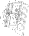
Fig. 1 is a perspective view of a clamping band attachment apparatus according to the present invention. -
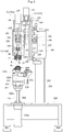
Fig. 2 is a side view of the clamping band attachment apparatus illustrated inFig. 1 . -
Fig. 3 is an enlarged side view of a main part of the clamping band attachment apparatus illustrated inFig. 1 . -
Fig. 4 is a perspective view of a main part of the clamping band attachment apparatus illustrated inFig. 1 . -
Fig. 5 is an enlarged view illustrating a partial cross section of claw members in an open state of the clamping band attachment apparatus illustrated inFig. 1 . -
Fig. 6 is an enlarged view illustrating a partial cross section of the claw members in a closed state of the clamping band attachment apparatus illustrated inFig. 1 . -
Fig. 7 is an enlarged view illustrating a free state of a sliding body of the clamping band attachment apparatus illustrated inFig. 1 . -
Fig. 8 is an enlarged view illustrating a pushed-up state of the sliding body of the clamping band attachment apparatus illustrated inFig. 1 . -
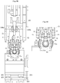
Fig. 9A is a side view illustrating a state where the claw members in the open state are lowered and illustrating a relationship between a wedge member and the claw members. -
Fig. 9B is an enlarged view of a main part ofFig. 9A . -
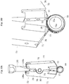
Fig. 10A is a perspective view illustrating the state where the claw members in the open state are lowered and illustrating the relationship between the wedge member and the claw members. -
Fig. 10B is an enlarged perspective view of a main part ofFig. 10A . -
Fig. 11 is a side view of a state where caulking is performed with the claw members. -
Fig. 12 is a plan view illustrating a fastening band. -
Fig. 13 is a side view of the fastening band illustrated inFig. 12 . -
Fig. 14 is a transverse cross-sectional view of a material before being drawn in a state where the fastening band illustrated inFig. 12 is rounded in a ring shape. -
Fig. 15A is a simplified view illustrating a method of mounting the fastening band, before clamping. -
Fig. 15B is a simplified view illustrating the method of mounting the fastening band, after clamping. -
Fig. 16 is a cross-sectional view of a drive shaft. -
Fig. 17 is a plan view of a conventional fastening band. -
Fig. 18A is a simplified perspective view illustrating a conventional method of mounting the fastening band, before clamping. -
Fig. 18B is a simplified perspective view illustrating the conventional method of mounting the fastening band, in the middle of clamping. -
Fig. 18C is a simplified perspective view illustrating the conventional method of mounting the fastening band, after clamping. -
Fig. 19A is a simplified view illustrating the conventional method of mounting the fastening band, before clamping. -
Fig. 19B is a simplified view illustrating the conventional method of mounting the fastening band, after clamping. - An embodiment of the present invention will be described below with reference to
Figs. 1 to 16 .Fig. 16 illustrates a drive shaft on which a fastening band is mounted using a band attachment apparatus of the present invention. The drive shaft includes a fixed-type constant velocityuniversal joint 21, a sliding-type constant velocityuniversal joint 22, and ashaft 23 connecting the constant velocity universal joints. In the example illustrated inFig. 16 , a Birfield constant velocity universal joint is used as the fixed-type constant velocityuniversal joint 21, and a tripod constant velocity universal joint is used as the sliding-type constant velocityuniversal joint 22. - The fixed-type constant velocity
universal joint 21 includes: an outerjoint member 26 having a plurality oftracks 24 extending axially and formed on an innerspherical surface 25; an innerjoint member 29 having a plurality oftracks 27 extending axially and formed on an outerspherical surface 28; a plurality ofballs 30 interposed between thetracks 24 of the outerjoint member 26 and thetracks 27 of the innerjoint member 29 to transmit torque; and acage 31 interposed between the innerspherical surface 25 of the outerjoint member 26 and the outerspherical surface 28 of the innerjoint member 29 to hold the balls. - The sliding-type constant velocity
universal joint 22 includes: an outerjoint member 33 which has threegrooves 32 extending in the axial direction on the inner periphery thereof, and roller-ring guide surfaces 32a facing each other and formed on an inner side wall of eachgroove 32; atripod member 35 which includes threeleg shafts 34 protruding in the radial direction and serving as an inner joint member; and aroller ring 36 which is rotatably supported by theleg shaft 34, is rotatably inserted into thegroove 32 of the outerjoint member 33 so as to freely roll, and serves as a torque transmission member. In this case, theroller ring 36 is externally fitted to the outer circumferential surface of theleg shaft 34 via a plurality ofrollers 37 arranged along the circumferential direction. Note that thetripod member 35 includes aboss portion 38 and theleg shafts 34 extending radially from theboss portion 38. -
Male splines shaft 23. Themale spline 23a on one side is fitted into the innerjoint member 29 of the fixed-type constant velocityuniversal joint 21, and themale spline 23b on the other side is fitted into thetripod member 35 of the sliding-type constant velocityuniversal joint 22. Afemale spline 40 is formed in an axial hole of the innerjoint member 29. Themale spline 23a on the one side of theshaft 23 is fitted into the axial hole of the innerjoint member 29 and meshes with thefemale spline 40. Themale spline 23b on the other side of theshaft 23 is fitted into an axial hole of theboss portion 38 of thetripod member 35 and meshes with afemale spline 40 of the axial hole. - A boot 45 (45A) for sealing an opening of the outer
joint member 26 is attached to the fixed-type constant velocityuniversal joint 21. A boot 45 (45B) for sealing an opening of the outerjoint member 33 is attached to the sliding-type constant velocityuniversal joint 22. Each of theboots band mounting portion 46a, a small-diameterband mounting portion 46b, and abellows portion 46c constituting a bent portion connecting the large-diameterband mounting portion 46a and the small-diameterband mounting portion 46b. The large-diameterband mounting portions 46a of theboots boot mounting portions joint members band mounting portions 46b of theboots portions 47, 47) of theshaft 23. - The
fastening band 50 is formed of a belt-shapedmember 51 as illustrated inFigs. 12 to 14 . The belt-shapedmember 51 made of metal has anarrow portion 52 formed on one end side thereof, and aprotrusion portion 53 provided near thenarrow portion 52 and protruding toward afront surface 51a side. Furthermore, aprotrusion portion 54 and engagingpieces front surface 51a side are provided on aprotrusion portion 53 side. In addition, anelongated hole 56 having a rectangular shape and an engaginghole 57 having a square shape are provided on the other end side of the belt-shapedmember 51. Aprotrusion portion 58 protruding toward thefront surface 51a side is provided on the side opposite to the engaginghole 57 of theelongated hole 56 having a rectangular shape. - The
protrusion portion 53 and theprotrusion portion 58 are constituted of triangular bodies configured of a pair ofinclined pieces protrusion portion 54 is configured of anupright piece 54a erected and protruding from thefront surface 51a of the belt-shapedmember 51, and aparallel piece 54b extending substantially parallel to the belt-shapedmember 51 from theupright piece 54a. In addition, each of the engagingpieces fastening band 50; however, the material is not limited to them. That is, it is possible to select a material which has rigidity enabling clamping of the large-diameter portion 46a and the small-diameter portion 46b of theboot 45 and capable of maintaining this state, and which hardly deteriorates in a use environment, or the like of this constant velocity universal joint. - A method of clamping the
band 50 configured as described above will be described. First, as illustrated inFig. 14 , aring portion 60 is formed by rounding thefastening band 50 into a ring shape. In this rounding, thefastening band 50 is rounded such that the one end side where theprotrusion portions pieces Fig. 12 ) and the engaging hole 57 (seeFig. 12 ) are provided. Then, as a diameter-reduced initial state, theprotrusion portion 53 on the one end side is fitted into theelongated hole 56 from the inner side. In this case, theprotrusion portion 53 is positioned closer to the engaginghole 57 in theelongated hole 56. - Then, the
protrusion portion 53 and theprotrusion portion 58 are brought close to each other by using a band attachment apparatus for the constant velocity universal joint according to the present invention. As a result, thering portion 60 configured of the belt-shapedmember 51 is reduced in diameter. That is, since theprotrusion portion 53 is provided on the one end side and theprotrusion portion 58 is provided on the other end side, thering portion 60 is reduced in diameter by bringing theprotrusion portion 53 and theprotrusion portion 58 close to each other. - Then, the engaging
piece 55a is engaged with theelongated hole 56, and theengaging piece 55b is engaged with the engaginghole 57. That is, the pair of engagingpieces partition portion 61 between theelongated hole 56 and the engaginghole 57. As a result, this diameter-reduced state can be maintained. - Next, a clamping band attachment apparatus according to the present invention will be described. As illustrated in
Figs. 1 ,2 , and the like, this clamping band attachment apparatus includes: a pair of clamping means 73A, 73B each having a pair ofclaw members claw members diameter portion 46a or the small-diameter portion 46b) of theboot 45; and swinging means 75 (75A, 75B) which swing theclaw members - As illustrated in
Figs. 5 to 9B , theclaw members claw members main body 76 and a slidingbody 77 in which a frontend engagement portion claw member 71 on one side has a protrudingrib 78 for pivotal support which is provided substantially at the center in the longitudinal direction on the inner surface (surface facing theclaw member 72 on the other side) of the claw membermain body 76. Theclaw member 72 on the other side has a pair of protrudingribs rib 78 and are provided on the inner surface (surface facing theclaw member 71 on the one side) of the claw membermain body 76. Through holes are provided in the protrudingrib 78 and the protrudingribs shaft 80 is fitted into the through holes. As a result, theclaw members - The sliding
body 77 has afirst block body 81 constituting the frontend engagement portion 71a (72a), and asecond block body 82 integrated with thefirst block body 81. Thesecond block body 82 has acutout portion 83 in which thefirst block body 81 is fitted, and a projectingportion 84 fitted in a recessedportion 85 provided in the claw membermain body 76. The claw membermain body 76 is provided with acutout portion 76a in which the slidingbody 77 is fitted, and the recessedportion 85 is formed in thecutout portion 76a. - The
first block body 81 and thesecond block body 82 are integrated via a bolt member, not illustrated. That is, ascrew hole 86 is provided in thefirst block body 81, and a throughhole 87 in thesecond block body 82 through which the bolt member is inserted is provided. In addition, the claw membermain body 76 is provided with a throughhole 88 corresponding to the throughhole 87 of thesecond block body 82. Therefore, by inserting the bolt member (not illustrated), through the throughhole 88 into the throughhole 87 and screwing the bolt member in thescrew hole 86, thefirst block body 81 and thesecond block body 82 are integrated. - The sliding
body 77 can reciprocate along the axial direction of the claw membermain body 76 in a state of being fitted in thecutout portion 76a of the claw membermain body 76. In this case, apin member 89 is provided on a claw membermain body 76 side, and anelongated hole 90 for guide is provided in thesecond block body 82 of the slidingbody 77. Thepin member 89 is fitted into theelongated hole 90 to regulate sliding length. - A recessed
portion 84a is provided in the projectingportion 84 of thesecond block body 82. A recessedportion 85c is provided in abottom surface 85b of the recessedportion 85 of thecutout portion 76a of the claw membermain body 76. Anelastic member 91 configured of a coil spring is fitted in the recessedportion 84a and the recessedportion 85c. For this reason, normally (in a free state), due to elastic force of theelastic member 91, the slidingbody 77 is pressed in a direction of arrow C toward a front end side, and thepin member 89 is positioned at the upper end of theelongated hole 90. Sliding of the slidingbody 77 further in the direction of arrow C is restricted. If the slidingbody 77 is pushed up in a direction of arrow D against the elastic force of theelastic member 91 from the state illustrated inFigs. 5 to 7 , the slidingbody 77 slides in the direction of arrow D as illustrated inFig. 8 . In this case, the slidingbody 77 slides in the direction of arrow D either until anend surface 84b of the projectingportion 84 of thesecond block body 82 abuts against thebottom surface 85b of the recessedportion 85 of thecutout portion 76a of the claw membermain body 76, or until thepin member 89 is positioned at the lower edge of theelongated hole 90. - The swinging means 75 includes a
wedge member 100 and a vertical movement mechanism 101 (seeFig. 2 and the like) which vertically moves thewedge member 100. As illustrated inFig. 3 and the like, thewedge member 100 has taperedsurfaces wedge member 100 tapered toward the lower end. As illustrated inFig. 2 , thevertical movement mechanism 101 is configured of a screw shaft mechanism having ascrew shaft 102 and anut member 103 screwed to thescrew shaft 102. In this case, thescrew shaft 102 is rotated about the axis thereof by a driving motor (for example, a servomotor) 107 supported by a supportingmember 106 of a vertically slidingframe body 105. - Therefore, when the driving
motor 107 is driven to rotate, thescrew shaft 102 rotates around the axis thereof, and thenut member 103 vertically moves while being guided by the vertically slidingframe body 105. Thewedge member 100 moves vertically in conjunction with vertical movement of thenut member 103. - As illustrated in
Fig. 3 , guiderollers claw members Fig. 5 , in a state where the frontend engagement portions 71a (72a) are expanded, front ends of the taperedsurfaces wedge member 100 are clamped by theguide rollers claw members shaft 80. - If the
wedge member 100 is lowered as illustrated inFig. 6 from the state illustrated inFig. 5 , thewedge member 100 enters a gap on the base end sides of theclaw members claw members end engagement portions claw members shaft 80 against the elastic biasing force which causes theclaw members - When an external force against the elastic force of the elastic member acts on the sliding
body 77 in the direction of arrow D from the state illustrated inFig. 6 , that is, the free state, the slidingbody 77 slides in the direction of arrow D as illustrated inFig. 8 (Fig. 8 illustrates a state where only aclaw member 72 side slides for the sake of explanation). That is, the slidingbody 77 moves backward from the state illustrated inFig. 6 . In addition, when the pressing force caused by the external force is released, the slidingbody 77 slides in the direction of arrow C due to the elastic force of theelastic member 91 and returns to the state illustrated inFig. 6 , that is, the free state. - As illustrated in
Figs. 1 and2 , the clamping band attachment apparatus includes abase 200, aworkpiece placement stage 201 provided on thebase 200, and apillar member 202 erected on thebase 200. - The
pillar member 202 is configured of a pair ofstruts support frame body 204 transversely stretched. The reciprocating means 74 (74A, 74B) are attached to thesupport frame body 204 via ahorizontal slide mechanism 205. Thehorizontal slide mechanism 205 includes ascrew shaft 206 disposed along the horizontal direction, and anut member 207 screwed to thescrew shaft 206.Frame bodies nut member 207. In addition, aguide mechanism 209 is provided between thesupport frame body 204 and theframe bodies guide mechanism 209 has a pair ofguide rails support frame body 204 along the horizontal direction, andsliders frame bodies sliders guide rails screw shaft 206 is rotated about the axis thereof by driving a driving motor, not illustrated, thenut member 207 reciprocates in the horizontal direction. As a result, theframe bodies - The reciprocating means 74 includes a driving motor (servomotor) 121 erected on a horizontal supporting
plate member 120 of theframe body 208, ascrew shaft 122 connected to an output shaft of the drivingmotor 121 and disposed along the vertical direction, and anut portion 123 screwed to thescrew shaft 122. In this case, the vertically slidingframe body 105 of the swinging means 75 is provided on thenut portion 123. - Therefore, when the driving
motor 121 of the reciprocating means 74 is driven, thescrew shaft 122 rotates about the axis thereof, and the vertically slidingframe body 105 to which thenut portion 123 is attached moves vertically. Aguide mechanism 125 is provided between the vertically slidingframe body 105 and theframe body 208. Theguide mechanism 125 includes aguide rail 126 disposed on theframe body 208 along the perpendicular direction (vertical direction), and aslider 127 provided in the vertically slidingframe body 105. Theslider 127 is slidably fitted in theguide rail 126. Therefore, the vertically slidingframe body 105 is guided by theguide mechanism 125 and moves vertically. - The
workpiece placement stage 201 is provided with a pair ofworkpiece receivers workpiece receivers bases guide rails workpiece placement stage 201. That is,sliders guide rails bases workpiece receivers band receiver 223a for receiving thefastening band 50 attached to the large-diameter portion 45a of theboot 45, and aband receiver 223b for receiving thefastening band 50 attached to the small-diameter portion 45b of theboot 45. - The
workpiece placement stage 201 can be vertically moved by acylinder mechanism 225 attached to thebase 200. That is, a cylindermain body 225a of thecylinder mechanism 225 is suspended and fixed from thebase 200, and apiston rod 225b of thecylinder mechanism 225 is connected to theworkpiece placement stage 201. A pair ofguide rods base 200, and theguide rods workpiece placement stage 201. - Therefore, the
workpiece placement stage 201 is guided by theguide rods cylinder mechanism 225. By sliding theworkpiece receivers guide rail 221, it is possible to make theworkpiece receivers - Next, a band attachment method using the clamping band attachment apparatus configured as described above will be described. First, as illustrated in
Fig. 1 , the drive shaft which is a workpiece W is set in theworkpiece receivers workpiece placement stage 201. In this case, the positions of theworkpiece receivers universal joint 21 and the sliding-type constant velocity universal joint 22 (seeFig. 16 ) such that thefastening band 50 of theband mounting portion 45a (seeFig. 16 ) of theboot 45 is received by theband receiver 223a and thefastening band 50 of the band mounting portion 45b of theboot 45 is received by theband receiver 223b, as illustrated inFig. 4 . - At this time, as illustrated in
Fig. 15A , thefastening band 50 is brought into the diameter-reduced initial state where theprotrusion portion 53 on the one end side is fitted into theelongated hole 56 from the inner side and theprotrusion portion 53 is positioned closer to the engaginghole 57 in theelongated hole 56. Then, the pair of clamping means 73A, 73B is positioned above thefastening bands 50. At this time, as illustrated inFig. 3 , each of theclaw members end engagement portions 71a (72a) are expanded. - In this state, the
claw members band mounting portion 46a (46b) of theboot 45, that is, thefastening band 50, via the reciprocating means 74. As illustrated inFigs. 9A, 9B ,10A, and 10B , theprotrusion portions end engagement portions 71a (72a). Next, thewedge member 100 is lowered so that the frontend engagement portions 71a (72a) of theclaw members Fig. 11 . - That is, if the front
end engagement portions 71a (72a) of theclaw members protrusion portions end engagement portions 71a (72a) as illustrated inFig. 15A , a load in a direction of arrow E is applied to thefastening band 50 as illustrated inFig. 11 . That is, by bringing the frontend engagement portions 71a (72a) close to each other as indicated by arrows B as illustrated inFig. 15B , theclaw members - However, since each of the
claw members body 77 formed with the frontend engagement portion 71a (72a), the slidingbody 77 can escape as illustrated inFig. 8 . Therefore, as illustrated inFig. 11 , the above-described load can be canceled. That is, by having such a slidingbody 77, the frontend engagement portion 71a (72a) can draw a locus along the outer circumference of the band, and automatic band caulking can be performed even for a small-diameter workpiece. At this time, as described above, the engagingpiece 55b is engaged with the engaginghole 57 and theengaging piece 55a is engaged with the elongated hole 56 (seeFig. 12 ). That is, the pair of engagingpieces partition portion 61 between theelongated hole 56 and the engaginghole 57. As a result, this diameter-reduced state can be maintained. - According to the present invention, the
claw members band mounting portions 45a, 45b of theboot 45 via the reciprocating means 74. In addition, theclaw members claw members claw members claw members band mounting portions 45a, 45b. Then, the pair ofprotrusion portions end engagement portions claw members claw members ring portion 60 can be reduced. At this time, the protrusion portions are displaced in the radial and circumferential directions, accompanying the diameter reduction of thering portion 60. However, it is possible for the slidingbody 77 having the frontend engagement portion ring portion 60. - The sliding
body 77 is attached to the claw membermain body 76 via theelastic member 91 that elastically presses the slidingbody 77 toward the front end side to bring the slidingbody 77 in a forward state in the free state, and allows the slidingbody 77 to move backward upon contact with thering portion 60, or theprotrusion portion end engagement portions end engagement portions protrusion portions - The swinging means 75 includes the
wedge member 100 which expands and reduces the interval between the frontend engagement portions claw members claw members shaft 80. With this configuration, by inserting thewedge member 100 between the pair ofclaw members end engagement portions wedge member 100 from between the pair ofclaw members end engagement portions - As described above, in the present invention, it is possible to reduce the diameter of the ring portion without using a control mechanism or the like and without performing manual work by a worker for the radial and circumferential displacement of the
protrusion portions boot 45 on theboot mounting portions 45a, 45b. Therefore, work efficiency can be improved and cost can be reduced. - In addition, by setting the sliding
bodies claw members ring portion 60 without being affected by variation in the shape of thering portion 60. It is possible to stably reduce the diameter of thering portion 60 without forming thering portion 60 formed by rolling the belt-shapedmember 51 in a ring shape with high accuracy. - Although the embodiment of the present invention has been described above, the present invention is not limited to the above-described embodiment, and various modifications are possible. For example, the apparatus illustrated in the embodiment includes the pair of clamping means 73A, 73B, the pair of reciprocating means 74A, 74B, and the pair of swinging means 75A, 75B, and can perform simultaneous caulking operations of the
fastening bands 50 on the large-diameter side and the small-diameter side. However, there may be time difference between caulking operations. The number of each of the above means may be one, and caulking operation of one of thebands 50 on the large-diameter side and the small-diameter side may be performed and then caulking operation of the other band may be performed. - In the
wedge member 100, the inclination angles of the taperedsurfaces claw members Figs. 9A,9B and10 , and theclaw members Fig. 11 . In addition, in the above-described embodiment, thewedge member 100 is tapered downward; however, thewedge member 100 may increase in width (widen) downward. In this case, thewedge member 100 may be set such that when theclaw members Fig. 9 , thewedge member 100 is brought into a state of entering (being fitted in) the gap on the base end sides of theclaw members wedge member 100 in a direction separating from the gap from this state, theclaw members - The boot to be used may be a resin boot or a rubber boot. In addition, the fixed-type constant velocity universal joint of the drive shaft as the workpiece W may be a Birfield-type or an undercut free-type joint. The sliding-type constant velocity universal joint may be a double offset-type, a tripod-type, or a cross groove-type joint or the like.
-
- 45 (45A, 45B): Boot
- 46a: Band mounting portion (Large-diameter portion)
- 46b: Band mounting portion (Small-diameter portion)
- 51: Belt-shaped member
- 53, 58: Protrusion portion
- 60: Ring portion
- 71, 72: Claw member
- 71a, 72a: Front end engagement portion
- 73 (73A, 73B): Clamping means
- 74 (74A, 74B): Reciprocating means
- 75 (75A, 75B): Swinging means
- 76: Claw member main body
- 77: Sliding body
- 80: Pivotal supporting shaft
- 91: Elastic member
- 100: Wedge member
Claims (5)
- A band attachment method comprising:rounding a belt-shaped member in a ring shape and forming a ring portion which is externally fitted to a band mounting portion of a boot, the ring portion being formed with a pair of protrusion portions separated at a predetermined pitch along a circumferential direction; andbringing the pair of protrusion portions close to each other in the circumferential direction so as to reduce a diameter of the ring portion,wherein in a state where the pair of protrusion portions of the ring portion are clamped by front end engagement portions of a pair of claw members, the sliding bodies slide with contact of the front end engagement portions to one of the ring portion and the pair of protrusion portions of the ring portion so as to follow a radial and circumferential displacement of the pair of protrusion portions accompanying a diameter reduction of the ring portion while the front end engagement portions of the pair of claw members are swung in a direction approaching each other about a pivotal supporting portion.
- The band attachment method according to claim 1, wherein each of the sliding bodies of the pair of claw members is independently slidable.
- A clamping band attachment apparatus rounding a belt-shaped member in a ring shape and forming a ring portion externally fitted to a band mounting portion of a boot, the ring portion being formed with a pair of protrusion portions separated at a predetermined pitch along a circumferential direction, and bringing the pair of protrusion portions close to each other in the circumferential direction so as to reduce a diameter of the ring portion, the clamping band attachment apparatus comprising:clamping means which has a pair of claw members that swing in a direction in which front end engagement portions of the pair of claw members approach and separate from each other about a pivotal supporting portion;reciprocating means which reciprocates the pair of claw members of the clamping means in a direction approaching and separating from the band mounting portion of the boot; andswinging means which swings the pair of claw members of the clamping means in a direction approaching and separating from each other, wherein each of the pair of claw members includes a claw member main body and a sliding body formed with each of the front end engagement portions, andwherein in a state where the pair of protrusion portions of the ring portion are clamped by the front end engagement portions of the pair of claw members, the sliding body formed with each of the front end engagement portions is slidably attached to the claw member main body so as to follow a radial and circumferential displacement of each of the pair of protrusion portions accompanying a diameter reduction of the ring portion while the front end engagement portions of the pair of claw members are swung in the direction approaching each other about the pivotal supporting portion.
- The clamping band attachment apparatus according to claim 3, wherein the sliding body is attached to the claw member main body via an elastic member that elastically presses the sliding body toward a front end side to bring the sliding body in a forward state in a free state, and allows the sliding body to move backward upon contact with one of the ring portion and each of the protrusion portions of the ring portion in a state where the front end engagement portions are brought close to each other.
- The clamping band attachment apparatus according to claim 3 or 4 wherein the swinging means includes a wedge member which expands and reduces an interval between the front end engagement portions of the pair of claw members by reciprocating in an axial direction between the pair of claw members on a rear end side with respect to the pivotal supporting shaft.
Applications Claiming Priority (2)
| Application Number | Priority Date | Filing Date | Title |
|---|---|---|---|
| JP2015195960A JP6576778B2 (en) | 2015-10-01 | 2015-10-01 | Fastening band mounting method and tightening band mounting device |
| PCT/JP2016/075913 WO2017056852A1 (en) | 2015-10-01 | 2016-09-02 | Clamping band attachment method and clamping band attachment apparatus |
Publications (2)
| Publication Number | Publication Date |
|---|---|
| EP3358203A1 true EP3358203A1 (en) | 2018-08-08 |
| EP3358203A4 EP3358203A4 (en) | 2019-05-22 |
Family
ID=58423325
Family Applications (1)
| Application Number | Title | Priority Date | Filing Date |
|---|---|---|---|
| EP16851028.7A Withdrawn EP3358203A4 (en) | 2015-10-01 | 2016-09-02 | Clamping band attachment method and clamping band attachment apparatus |
Country Status (5)
| Country | Link |
|---|---|
| US (1) | US10610987B2 (en) |
| EP (1) | EP3358203A4 (en) |
| JP (1) | JP6576778B2 (en) |
| CN (1) | CN108138819B (en) |
| WO (1) | WO2017056852A1 (en) |
Cited By (1)
| Publication number | Priority date | Publication date | Assignee | Title |
|---|---|---|---|---|
| EP4317712A4 (en) * | 2021-03-24 | 2024-11-20 | NTN Corporation | Method for fixing boot to constant-velocity universal joint |
Families Citing this family (4)
| Publication number | Priority date | Publication date | Assignee | Title |
|---|---|---|---|---|
| CN113751995B (en) * | 2020-06-02 | 2023-03-21 | 中车唐山机车车辆有限公司 | Press fitting tool |
| CN112091595B (en) * | 2020-09-08 | 2024-10-18 | 安徽航大智能科技有限公司 | Automatic locking plate mechanism for locking differential nut |
| CN113231977A (en) * | 2021-05-07 | 2021-08-10 | 中国第一汽车股份有限公司 | Gasket and pin shaft hole centering device |
| CN113198644A (en) * | 2021-05-25 | 2021-08-03 | 嘉兴学院 | Conveying device with positioning structure for spraying brake disc |
Family Cites Families (7)
| Publication number | Priority date | Publication date | Assignee | Title |
|---|---|---|---|---|
| JPH0639651A (en) | 1992-07-28 | 1994-02-15 | Toshiba Corp | Parts insertion hand |
| JP3027903B2 (en) * | 1994-03-17 | 2000-04-04 | 三菱自動車エンジニアリング株式会社 | Clamp band tightening device |
| BE1015486A3 (en) * | 1999-09-30 | 2005-05-03 | Honda Motor Co Ltd | Clamping fixation band to boot for uniform-velocity joint of a vehicle, involves pressing protrusion of fixation band set in fixed position and rotated with boot to tightly bind flexible band to boot |
| JP3335601B2 (en) * | 1999-10-29 | 2002-10-21 | ジーケーエヌジャパンドライブシャフト株式会社 | Boot band mounting method and mounting device |
| JP4318824B2 (en) | 2000-02-09 | 2009-08-26 | 本田技研工業株式会社 | Fastening band and fastening method thereof |
| JP2006316979A (en) * | 2005-05-16 | 2006-11-24 | Honda Motor Co Ltd | Clamping band tightening method for constant velocity joints |
| WO2013008585A1 (en) | 2011-07-12 | 2013-01-17 | Ntn株式会社 | Clamping method and clamping device |
-
2015
- 2015-10-01 JP JP2015195960A patent/JP6576778B2/en active Active
-
2016
- 2016-09-02 US US15/764,966 patent/US10610987B2/en not_active Expired - Fee Related
- 2016-09-02 EP EP16851028.7A patent/EP3358203A4/en not_active Withdrawn
- 2016-09-02 WO PCT/JP2016/075913 patent/WO2017056852A1/en not_active Ceased
- 2016-09-02 CN CN201680057332.0A patent/CN108138819B/en not_active Expired - Fee Related
Cited By (1)
| Publication number | Priority date | Publication date | Assignee | Title |
|---|---|---|---|---|
| EP4317712A4 (en) * | 2021-03-24 | 2024-11-20 | NTN Corporation | Method for fixing boot to constant-velocity universal joint |
Also Published As
| Publication number | Publication date |
|---|---|
| JP2017067234A (en) | 2017-04-06 |
| CN108138819A (en) | 2018-06-08 |
| US10610987B2 (en) | 2020-04-07 |
| EP3358203A4 (en) | 2019-05-22 |
| US20180200849A1 (en) | 2018-07-19 |
| CN108138819B (en) | 2020-08-04 |
| JP6576778B2 (en) | 2019-09-18 |
| WO2017056852A1 (en) | 2017-04-06 |
Similar Documents
| Publication | Publication Date | Title |
|---|---|---|
| US10610987B2 (en) | Clamping band attachment method and clamping band attachment apparatus | |
| JP6782336B2 (en) | Roller set and pipe elements | |
| US9212684B2 (en) | Rivet nut unit | |
| US12064841B2 (en) | Device for installing retaining ring on shaft | |
| KR101509920B1 (en) | a coupling for aluminum profile | |
| EP2806180A2 (en) | Direct pinion mount rzeppa joint | |
| RU2706592C1 (en) | Deflector element for arrangement between two parts of vehicle of rail transport | |
| KR101542683B1 (en) | Mandrel with a universal joint | |
| US9993901B2 (en) | Clamping device | |
| MX2021009692A (en) | Tool for friction stir welding and method for producing panels. | |
| CN205333307U (en) | A experimental frock for shift fork capability test | |
| US2442640A (en) | Method of installing boots on universal joints | |
| CN110446568A (en) | Component joining device and component joining method | |
| US3722066A (en) | Apparatus and method for assembling universal joints | |
| KR20180074224A (en) | Band clamping apparatus | |
| KR20160061724A (en) | Apparatus for bolt hole | |
| CN113478409A (en) | Flexible clamp suitable for crank connecting rod with different apertures and hole distances | |
| JP5777993B2 (en) | Boot mounting method for constant velocity universal joint and boot mounting apparatus for constant velocity universal joint | |
| JP2019035487A (en) | Position fixing jig and clamping device | |
| CN107695669B (en) | Adjustable self-aligning quick-connect fastening method and system | |
| CN104760019B (en) | Thermal-collecting tube installation tool | |
| CN106312535A (en) | Lateral screwing device used for screw | |
| CN106855073B (en) | A kind of attachment and its application method connected for electric power cabinet | |
| CN120292190A (en) | A bearing ball and spacer block filling auxiliary tool | |
| KR101538336B1 (en) | Method for connecting pipe connection and pipe |
Legal Events
| Date | Code | Title | Description |
|---|---|---|---|
| PUAI | Public reference made under article 153(3) epc to a published international application that has entered the european phase |
Free format text: ORIGINAL CODE: 0009012 |
|
| 17P | Request for examination filed |
Effective date: 20180425 |
|
| AK | Designated contracting states |
Kind code of ref document: A1 Designated state(s): AL AT BE BG CH CY CZ DE DK EE ES FI FR GB GR HR HU IE IS IT LI LT LU LV MC MK MT NL NO PL PT RO RS SE SI SK SM TR |
|
| AX | Request for extension of the european patent |
Extension state: BA ME |
|
| DAV | Request for validation of the european patent (deleted) | ||
| DAX | Request for extension of the european patent (deleted) | ||
| A4 | Supplementary search report drawn up and despatched |
Effective date: 20190418 |
|
| RIC1 | Information provided on ipc code assigned before grant |
Ipc: B23P 19/08 20060101ALI20190412BHEP Ipc: F16D 3/84 20060101ALI20190412BHEP Ipc: F16B 2/08 20060101AFI20190412BHEP Ipc: B23P 21/00 20060101ALI20190412BHEP |
|
| GRAP | Despatch of communication of intention to grant a patent |
Free format text: ORIGINAL CODE: EPIDOSNIGR1 |
|
| INTG | Intention to grant announced |
Effective date: 20200318 |
|
| STAA | Information on the status of an ep patent application or granted ep patent |
Free format text: STATUS: THE APPLICATION IS DEEMED TO BE WITHDRAWN |
|
| 18D | Application deemed to be withdrawn |
Effective date: 20200729 |