EP3358147A1 - Bypass valve system state indication - Google Patents
Bypass valve system state indication Download PDFInfo
- Publication number
- EP3358147A1 EP3358147A1 EP18152765.6A EP18152765A EP3358147A1 EP 3358147 A1 EP3358147 A1 EP 3358147A1 EP 18152765 A EP18152765 A EP 18152765A EP 3358147 A1 EP3358147 A1 EP 3358147A1
- Authority
- EP
- European Patent Office
- Prior art keywords
- bypass
- piston
- inlet
- outlet
- fluid
- Prior art date
- Legal status (The legal status is an assumption and is not a legal conclusion. Google has not performed a legal analysis and makes no representation as to the accuracy of the status listed.)
- Granted
Links
Images


Classifications
-
- F—MECHANICAL ENGINEERING; LIGHTING; HEATING; WEAPONS; BLASTING
- F02—COMBUSTION ENGINES; HOT-GAS OR COMBUSTION-PRODUCT ENGINE PLANTS
- F02C—GAS-TURBINE PLANTS; AIR INTAKES FOR JET-PROPULSION PLANTS; CONTROLLING FUEL SUPPLY IN AIR-BREATHING JET-PROPULSION PLANTS
- F02C7/00—Features, components parts, details or accessories, not provided for in, or of interest apart form groups F02C1/00 - F02C6/00; Air intakes for jet-propulsion plants
- F02C7/04—Air intakes for gas-turbine plants or jet-propulsion plants
- F02C7/05—Air intakes for gas-turbine plants or jet-propulsion plants having provisions for obviating the penetration of damaging objects or particles
- F02C7/052—Air intakes for gas-turbine plants or jet-propulsion plants having provisions for obviating the penetration of damaging objects or particles with dust-separation devices
-
- B—PERFORMING OPERATIONS; TRANSPORTING
- B01—PHYSICAL OR CHEMICAL PROCESSES OR APPARATUS IN GENERAL
- B01D—SEPARATION
- B01D35/00—Filtering devices having features not specifically covered by groups B01D24/00 - B01D33/00, or for applications not specifically covered by groups B01D24/00 - B01D33/00; Auxiliary devices for filtration; Filter housing constructions
- B01D35/14—Safety devices specially adapted for filtration; Devices for indicating clogging
- B01D35/143—Filter condition indicators
- B01D35/1435—Filter condition indicators with alarm means
-
- B—PERFORMING OPERATIONS; TRANSPORTING
- B01—PHYSICAL OR CHEMICAL PROCESSES OR APPARATUS IN GENERAL
- B01D—SEPARATION
- B01D35/00—Filtering devices having features not specifically covered by groups B01D24/00 - B01D33/00, or for applications not specifically covered by groups B01D24/00 - B01D33/00; Auxiliary devices for filtration; Filter housing constructions
- B01D35/14—Safety devices specially adapted for filtration; Devices for indicating clogging
- B01D35/147—Bypass or safety valves
- B01D35/1475—Pressure relief valves or pressure control valves
-
- B—PERFORMING OPERATIONS; TRANSPORTING
- B01—PHYSICAL OR CHEMICAL PROCESSES OR APPARATUS IN GENERAL
- B01D—SEPARATION
- B01D46/00—Filters or filtering processes specially modified for separating dispersed particles from gases or vapours
- B01D46/0084—Filters or filtering processes specially modified for separating dispersed particles from gases or vapours provided with safety means
- B01D46/0087—Bypass or safety valves
-
- F—MECHANICAL ENGINEERING; LIGHTING; HEATING; WEAPONS; BLASTING
- F01—MACHINES OR ENGINES IN GENERAL; ENGINE PLANTS IN GENERAL; STEAM ENGINES
- F01D—NON-POSITIVE DISPLACEMENT MACHINES OR ENGINES, e.g. STEAM TURBINES
- F01D17/00—Regulating or controlling by varying flow
- F01D17/02—Arrangement of sensing elements
- F01D17/08—Arrangement of sensing elements responsive to condition of working-fluid, e.g. pressure
-
- F—MECHANICAL ENGINEERING; LIGHTING; HEATING; WEAPONS; BLASTING
- F01—MACHINES OR ENGINES IN GENERAL; ENGINE PLANTS IN GENERAL; STEAM ENGINES
- F01D—NON-POSITIVE DISPLACEMENT MACHINES OR ENGINES, e.g. STEAM TURBINES
- F01D17/00—Regulating or controlling by varying flow
- F01D17/10—Final actuators
- F01D17/105—Final actuators by passing part of the fluid
-
- F—MECHANICAL ENGINEERING; LIGHTING; HEATING; WEAPONS; BLASTING
- F02—COMBUSTION ENGINES; HOT-GAS OR COMBUSTION-PRODUCT ENGINE PLANTS
- F02C—GAS-TURBINE PLANTS; AIR INTAKES FOR JET-PROPULSION PLANTS; CONTROLLING FUEL SUPPLY IN AIR-BREATHING JET-PROPULSION PLANTS
- F02C7/00—Features, components parts, details or accessories, not provided for in, or of interest apart form groups F02C1/00 - F02C6/00; Air intakes for jet-propulsion plants
- F02C7/04—Air intakes for gas-turbine plants or jet-propulsion plants
- F02C7/057—Control or regulation
-
- F—MECHANICAL ENGINEERING; LIGHTING; HEATING; WEAPONS; BLASTING
- F02—COMBUSTION ENGINES; HOT-GAS OR COMBUSTION-PRODUCT ENGINE PLANTS
- F02C—GAS-TURBINE PLANTS; AIR INTAKES FOR JET-PROPULSION PLANTS; CONTROLLING FUEL SUPPLY IN AIR-BREATHING JET-PROPULSION PLANTS
- F02C7/00—Features, components parts, details or accessories, not provided for in, or of interest apart form groups F02C1/00 - F02C6/00; Air intakes for jet-propulsion plants
- F02C7/22—Fuel supply systems
- F02C7/232—Fuel valves; Draining valves or systems
-
- F—MECHANICAL ENGINEERING; LIGHTING; HEATING; WEAPONS; BLASTING
- F16—ENGINEERING ELEMENTS AND UNITS; GENERAL MEASURES FOR PRODUCING AND MAINTAINING EFFECTIVE FUNCTIONING OF MACHINES OR INSTALLATIONS; THERMAL INSULATION IN GENERAL
- F16K—VALVES; TAPS; COCKS; ACTUATING-FLOATS; DEVICES FOR VENTING OR AERATING
- F16K17/00—Safety valves; Equalising valves, e.g. pressure relief valves
- F16K17/02—Safety valves; Equalising valves, e.g. pressure relief valves opening on surplus pressure on one side; closing on insufficient pressure on one side
- F16K17/04—Safety valves; Equalising valves, e.g. pressure relief valves opening on surplus pressure on one side; closing on insufficient pressure on one side spring-loaded
-
- F—MECHANICAL ENGINEERING; LIGHTING; HEATING; WEAPONS; BLASTING
- F16—ENGINEERING ELEMENTS AND UNITS; GENERAL MEASURES FOR PRODUCING AND MAINTAINING EFFECTIVE FUNCTIONING OF MACHINES OR INSTALLATIONS; THERMAL INSULATION IN GENERAL
- F16K—VALVES; TAPS; COCKS; ACTUATING-FLOATS; DEVICES FOR VENTING OR AERATING
- F16K37/00—Special means in or on valves or other cut-off apparatus for indicating or recording operation thereof, or for enabling an alarm to be given
- F16K37/0025—Electrical or magnetic means
-
- F—MECHANICAL ENGINEERING; LIGHTING; HEATING; WEAPONS; BLASTING
- F16—ENGINEERING ELEMENTS AND UNITS; GENERAL MEASURES FOR PRODUCING AND MAINTAINING EFFECTIVE FUNCTIONING OF MACHINES OR INSTALLATIONS; THERMAL INSULATION IN GENERAL
- F16K—VALVES; TAPS; COCKS; ACTUATING-FLOATS; DEVICES FOR VENTING OR AERATING
- F16K37/00—Special means in or on valves or other cut-off apparatus for indicating or recording operation thereof, or for enabling an alarm to be given
- F16K37/0025—Electrical or magnetic means
- F16K37/0041—Electrical or magnetic means for measuring valve parameters
-
- B—PERFORMING OPERATIONS; TRANSPORTING
- B01—PHYSICAL OR CHEMICAL PROCESSES OR APPARATUS IN GENERAL
- B01D—SEPARATION
- B01D2279/00—Filters adapted for separating dispersed particles from gases or vapours specially modified for specific uses
- B01D2279/60—Filters adapted for separating dispersed particles from gases or vapours specially modified for specific uses for the intake of internal combustion engines or turbines
-
- F—MECHANICAL ENGINEERING; LIGHTING; HEATING; WEAPONS; BLASTING
- F05—INDEXING SCHEMES RELATING TO ENGINES OR PUMPS IN VARIOUS SUBCLASSES OF CLASSES F01-F04
- F05D—INDEXING SCHEME FOR ASPECTS RELATING TO NON-POSITIVE-DISPLACEMENT MACHINES OR ENGINES, GAS-TURBINES OR JET-PROPULSION PLANTS
- F05D2230/00—Manufacture
- F05D2230/72—Maintenance
-
- F—MECHANICAL ENGINEERING; LIGHTING; HEATING; WEAPONS; BLASTING
- F05—INDEXING SCHEMES RELATING TO ENGINES OR PUMPS IN VARIOUS SUBCLASSES OF CLASSES F01-F04
- F05D—INDEXING SCHEME FOR ASPECTS RELATING TO NON-POSITIVE-DISPLACEMENT MACHINES OR ENGINES, GAS-TURBINES OR JET-PROPULSION PLANTS
- F05D2260/00—Function
- F05D2260/60—Fluid transfer
- F05D2260/606—Bypassing the fluid
-
- F—MECHANICAL ENGINEERING; LIGHTING; HEATING; WEAPONS; BLASTING
- F05—INDEXING SCHEMES RELATING TO ENGINES OR PUMPS IN VARIOUS SUBCLASSES OF CLASSES F01-F04
- F05D—INDEXING SCHEME FOR ASPECTS RELATING TO NON-POSITIVE-DISPLACEMENT MACHINES OR ENGINES, GAS-TURBINES OR JET-PROPULSION PLANTS
- F05D2260/00—Function
- F05D2260/60—Fluid transfer
- F05D2260/607—Preventing clogging or obstruction of flow paths by dirt, dust, or foreign particles
-
- F—MECHANICAL ENGINEERING; LIGHTING; HEATING; WEAPONS; BLASTING
- F05—INDEXING SCHEMES RELATING TO ENGINES OR PUMPS IN VARIOUS SUBCLASSES OF CLASSES F01-F04
- F05D—INDEXING SCHEME FOR ASPECTS RELATING TO NON-POSITIVE-DISPLACEMENT MACHINES OR ENGINES, GAS-TURBINES OR JET-PROPULSION PLANTS
- F05D2260/00—Function
- F05D2260/80—Diagnostics
-
- F—MECHANICAL ENGINEERING; LIGHTING; HEATING; WEAPONS; BLASTING
- F05—INDEXING SCHEMES RELATING TO ENGINES OR PUMPS IN VARIOUS SUBCLASSES OF CLASSES F01-F04
- F05D—INDEXING SCHEME FOR ASPECTS RELATING TO NON-POSITIVE-DISPLACEMENT MACHINES OR ENGINES, GAS-TURBINES OR JET-PROPULSION PLANTS
- F05D2270/00—Control
- F05D2270/80—Devices generating input signals, e.g. transducers, sensors, cameras or strain gauges
- F05D2270/806—Sonars
-
- F—MECHANICAL ENGINEERING; LIGHTING; HEATING; WEAPONS; BLASTING
- F05—INDEXING SCHEMES RELATING TO ENGINES OR PUMPS IN VARIOUS SUBCLASSES OF CLASSES F01-F04
- F05D—INDEXING SCHEME FOR ASPECTS RELATING TO NON-POSITIVE-DISPLACEMENT MACHINES OR ENGINES, GAS-TURBINES OR JET-PROPULSION PLANTS
- F05D2270/00—Control
- F05D2270/80—Devices generating input signals, e.g. transducers, sensors, cameras or strain gauges
- F05D2270/821—Displacement measuring means, e.g. inductive
-
- Y—GENERAL TAGGING OF NEW TECHNOLOGICAL DEVELOPMENTS; GENERAL TAGGING OF CROSS-SECTIONAL TECHNOLOGIES SPANNING OVER SEVERAL SECTIONS OF THE IPC; TECHNICAL SUBJECTS COVERED BY FORMER USPC CROSS-REFERENCE ART COLLECTIONS [XRACs] AND DIGESTS
- Y02—TECHNOLOGIES OR APPLICATIONS FOR MITIGATION OR ADAPTATION AGAINST CLIMATE CHANGE
- Y02T—CLIMATE CHANGE MITIGATION TECHNOLOGIES RELATED TO TRANSPORTATION
- Y02T50/00—Aeronautics or air transport
- Y02T50/60—Efficient propulsion technologies, e.g. for aircraft
Definitions
- This disclosure generally relates to bypass valves.
- Fluid passages in vehicles may, over time, accumulate impurities from the fluid flowing through such fluid passages.
- the impurities may cause blockages in the fluid passages.
- there may be a pressure differential between the fluid flow into the fluid passage (inlet flow) and the fluid flow out the fluid passage (outlet flow).
- the inlet flow may have a higher pressure than the outlet flow.
- a bypass valve may open to allow some of the inlet flow through the bypass valve to reduce the pressure.
- the bypass valve opening may indicate that the fluid passage (such as a filter or heat exchanger) may need to be replaced because there is significant buildup of impurities in the fluid passage.
- a fluid system may comprise a fluid passage comprising a passage inlet and a passage outlet, through which fluid may flow by entering the passage inlet as an inlet flow and exiting the passage outlet as an outlet flow; a bypass valve comprising a bypass inlet and a bypass outlet, the bypass inlet being in fluid communication with the passage inlet, wherein the bypass valve further comprises a piston coupled to a spring; and a position sensor coupled to the bypass valve and configured to detect a position of the piston in the bypass valve.
- the spring may retain the piston in a rest position, and the spring and the piston may be configured to block the fluid from passing through the bypass outlet in response to the inlet flow exerting a pressure below a bypass pressure threshold.
- the fluid passage may be at least one of an oil filter, a fuel filter, an air filter, or a heat exchanger.
- the position sensor may be at least one of a proximity probe, a linear variable differential transformer, a sonar device, or a magnetic pickup.
- the bypass valve may comprise a cap coupled to the spring, wherein the spring may be disposed between the cap and the piston, and the position sensor may be coupled to the cap.
- the piston may be in the rest position in the bypass outlet, wherein the bypass outlet comprises an outlet surrounding wall and a portion of the outlet surrounding wall is a bypass slack area, wherein the piston may be in the rest position in the bypass slack area, and the piston may be configured to move along the bypass slack area in response to a pressure threshold being reached by the inlet flow in the passage inlet before allowing fluid to flow through the bypass outlet.
- the piston may be in the rest position in the bypass inlet, wherein the bypass inlet comprises an inlet surrounding wall and a portion of the inlet surrounding wall adjacent to the bypass outlet is a bypass slack area, wherein the piston may be in the rest position at a slack area end furthest from the bypass outlet, and the piston is configured to move along the bypass slack area toward the bypass outlet in response to a pressure threshold being reached by the inlet flow in the passage inlet.
- the bypass valve may be configured to allow the piston to move along the bypass slack area in response to the pressure threshold being reached by the inlet flow in the passage inlet before allowing the fluid to pass through the bypass outlet.
- the bypass valve may be configured to pass the fluid through the bypass outlet in response to the piston moving past the bypass slack area caused by the inlet flow reaching the bypass pressure threshold, and in response to the piston moving past the bypass slack area, the bypass outlet is in fluid communication with the bypass inlet.
- the fluid system may further comprise a control system in electronic communication with the position sensor, wherein the position sensor transmits the position of the piston to the control system.
- the control system may comprise a processor and may be configured to determine at least one of an impending bypass flow through the bypass outlet in response to the piston being moved to a displaced position along the bypass slack area from the rest position without allowing the fluid to pass through the bypass outlet, or a bypass flow through the bypass outlet in response to the piston moving past the bypass slack area and allowing the fluid to pass through the bypass outlet.
- an aircraft may comprise a gas turbine engine and a fluid system at least one of coupled to, or in fluid communication with, the gas turbine engine.
- the fluid system may comprise a fluid passage comprising a passage inlet and a passage outlet, through which fluid may flow by entering the passage inlet as an inlet flow and exiting the passage outlet as an outlet flow; a bypass valve comprising a bypass inlet and a bypass outlet, the bypass inlet being in fluid communication with the passage inlet, wherein the bypass valve further comprises a piston coupled to a spring; and a position sensor coupled to the bypass valve and configured to detect a position of the piston in the bypass valve.
- the spring may retain the piston in a rest position, and the spring and the piston may be configured to block the fluid from passing through the bypass outlet in response to the inlet flow exerting a pressure below a bypass pressure threshold.
- the piston may be in the rest position in the bypass outlet, wherein the bypass outlet comprises an outlet surrounding wall and a portion of the outlet surrounding wall is a bypass slack area, wherein the piston may be in the rest position in the bypass slack area, and the piston may be configured to move along the bypass slack area in response to a pressure threshold being reached by the inlet flow in the passage inlet before allowing fluid to flow through the bypass outlet.
- the piston may be in the rest position in the bypass inlet, wherein the bypass inlet comprises an inlet surrounding wall and a portion of the inlet surrounding wall adjacent to the bypass outlet is a bypass slack area, wherein the piston may be in the rest position at a slack area end furthest from the bypass outlet, and the piston is configured to move along the bypass slack area toward the bypass outlet in response to a pressure threshold being reached by the inlet flow in the passage inlet.
- the aircraft may further comprise a control system in electronic communication with the position sensor, wherein the position sensor may transmit the position of the piston to the control system.
- the control system may comprise a processor and may be configured to determine at least one of an impending bypass flow through the bypass outlet in response to the piston being moved along the bypass slack area from the rest position without allowing the fluid to pass through the bypass outlet, or a bypass flow through the bypass outlet in response to the piston moving past the bypass slack area and allowing the fluid to pass through the bypass outlet.
- method for monitoring a fluid passage may comprise passing a fluid through the fluid passage in a fluid system by the fluid entering a fluid inlet as an inlet flow and exiting through a fluid outlet as an outlet flow, wherein the fluid system comprises a bypass valve having a bypass inlet fluidly coupled to a passage inlet and a bypass outlet, wherein the bypass valve further comprises a piston in the passage inlet coupled to a spring, wherein the spring retains the piston in a rest position, and the spring and the piston are configured to block the fluid from passing through the bypass outlet in response to the inlet flow exerting a pressure below a bypass pressure threshold; detecting, by a position sensor coupled to the bypass valve, a position of the piston in the passage inlet; and determining, by a processor, whether the piston has moved from the rest position.
- the bypass inlet may comprise an inlet surrounding wall and a portion of the inlet surrounding wall adjacent to the bypass outlet is a bypass slack area, wherein the piston is in the rest position at a slack area end furthest from the bypass outlet of the bypass slack area, and the piston is configured to move along the bypass slack area toward the bypass outlet in response to the pressure threshold being reached by the inlet flow in the passage inlet before allowing the fluid to pass through the bypass outlet.
- the method may further comprise determining, by the processor, an impending bypass flow in response to determining that the piston has moved from the rest position to a displaced position along the bypass slack area. In various embodiments, the method may further comprise determining, by the processor, a bypass flow in response to determining that the piston has moved from the rest position to a bypass position, wherein the bypass position is when the piston has moved past the bypass slack area, causing the fluid to pass through bypass outlet.
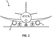
- Aircraft such as aircraft 50 depicted in FIG. 1 , may comprise a gas turbine engine 90.
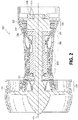
- a gas turbine engine 100 (such as a turbofan gas turbine engine) is illustrated according to various embodiments.
- Gas turbine engine 100 is disposed about axis of rotation 120.
- Gas turbine engine 100 may comprise a fan 140, compressor sections 150 and 160, a combustion section 180, and turbine sections 190, 191.
- Air compressed in compressor sections 150, 160 may be mixed with fuel and burned in combustion section 180 and expanded across turbine sections 190, 191.
- Turbine sections 190, 191 may include high pressure rotors 192 and low pressure rotors 194, which rotate in response to the expansion.
- Turbine sections 190, 191 may comprise alternating rows of rotary airfoils or blades 196 and static airfoils or vanes 198.
- a plurality of bearings 115 may support spools to which the rotors are affixed in gas turbine engine 100.
- FIG. 2 provides a general understanding of the sections in a gas turbine engine, and is not intended to limit the disclosure. The present disclosure may extend to all types of turbine engines, including turbofan gas turbine engines and turbojet engines, for all types of applications.
- the forward-aft positions of gas turbine engine 100 lie along axis of rotation 120.
- fan 140 may be referred to as forward of turbine section 190 and turbine section 190 may be referred to as aft of fan 140.
- aft of fan 140 Typically, during operation of gas turbine engine 100, air flows from forward to aft, for example, from fan 140 to turbine section 190.
- axis of rotation 120 may also generally define the direction of the air stream flow.
- aircraft 50 may comprise fluid passages, which may be any device used for the processing of fluid within the vehicle. Fluid passages may also be in fluid communication with or comprised in an engine within a vehicle (e.g., gas turbine engine 100).
- a fluid passage may be an oil filter, fuel filter, and/or an air filter implemented to remove impurities from the fluid (e.g., oil, fuel, and/or air, respectively), or a heat exchanger.
- FIG. 3 illustrates a fluid system 300 comprising a fluid passage 310, a bypass valve 350, and a control system 360.
- fluid passage 310 may comprise a passage inlet 302 through which the fluid to be processed (e.g., filtered, cooled, heated) may enter fluid passage 310 (i.e., an inlet flow 303), and a passage outlet 309 through which the processed fluid may exit fluid passage 310 (i.e., an outlet flow 308).
- the inlet flow pressure associated with the inlet flow 303 through passage inlet 302 may have a higher pressure than the outlet flow pressure associated with the outlet flow 308 through passage outlet 309.
- bypass valve 350 may be configured to relieve pressure in the inlet flow 303 of passage inlet 302 in response to the inlet flow pressure reaching a certain threshold (i.e., a "bypass pressure threshold").
- Bypass valve 350 may comprise a bypass inlet 348 in fluid communication with passage inlet 302, and a bypass outlet 352. If the inlet flow pressure in passage inlet 302 is below the bypass pressure threshold, bypass valve 350 may be closed such that no fluid may flow through bypass inlet 348 and/or bypass outlet 352. In response to the inlet flow 303 reaching the bypass pressure threshold, bypass valve 350 may open allowing fluid to pass through bypass valve 350 from bypass inlet 348 to bypass outlet 352 to relieve pressure from the inlet flow 303 in passage inlet 302.
- bypass outlet 352 may be in fluid communication with passage outlet 309, and therefore, in response to bypass valve 350 being open, fluid exiting bypass valve 350 through bypass outlet 352 may join the outlet flow 308 in passage outlet 309.
- bypass outlet 352 may be in fluid communication with other portions of fluid system 300 or other part of the vehicle comprising fluid system 300. In such embodiments, in response to bypass valve 350 being open, fluid exiting bypass valve 350 through bypass outlet 352 may travel to another part of fluid system 300 or the vehicle.
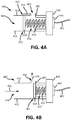
- a bypass valve 400 (an example of bypass valve 350 in FIG. 3 ) may comprise a bypass inlet 448 having an inlet surrounding wall 412, a bypass outlet 452 having an outlet surrounding wall 405, a piston 410 disposed in bypass inlet 448 and/or bypass outlet 452 blocking, a spring 415 coupled to the piston 410, a cap 430 coupled to spring 415, wherein spring 415 is coupled between piston 410 and cap 430, and/or a position sensor 440 configured to detect the position of piston 410.
- Inlet surrounding wall 412 and outlet surrounding wall 405 may be circular in cross section, or any suitable geometric shape (e.g., square, rectangle, octagon, hexagon, or the like).
- bypass inlet 448 may be in fluid communication with passage inlet 302.
- Piston 410 may be disposed in bypass inlet 448 and/or bypass outlet 452 such that piston 410 blocks the fluid from flowing through bypass outlet 452 of bypass valve 400.
- Spring 415 may retain piston 410 in a rest position 411 due to the bias of spring 415. When piston 410 is in rest position 411, spring 415 may be in a relaxed position 416.
- piston 410 may be disposed in bypass inlet 448, and therefore rest position 411 may be in bypass inlet 448 as well.
- the inlet flow pressure in passage inlet 302 may apply pressure on piston 410 and spring 415.
- Spring 415 may be configured to retain piston 410 in rest position 411.
- spring 415 may compress and piston 410 may move toward bypass outlet 452.
- the area of inlet surrounding wall 412 which spans between rest position 411 and bypass outlet 452 may be a bypass slack area 413, along which piston 410 may move as a result of inlet flow pressure increasing above the pressure threshold without opening bypass valve 400 by allowing fluid through bypass outlet 452.
- Piston 410 being moved from rest position 411 (located at a slack area end 422 of bypass slack area 413 furthest from bypass outlet 452) to a place along bypass slack area 413 such that piston 410 still blocks bypass outlet 452 may be referred to as an "impending bypass flow" because the inlet flow pressure will have almost reached the bypass pressure threshold which will open bypass outlet 452 (i.e., a bypass flow is impending).
- a position of piston 410 may referred to as a displaced position.
- the inlet flow pressure increasing to the pressure threshold, or above the pressure threshold, but below the bypass pressure threshold may move piston 410 along bypass slack area 413 toward bypass outlet 452.
- spring 415 may have been compressed enough by the inlet flow pressure to cause piston 410 to move in the direction of bypass inlet flow 402 past bypass slack area 413, and therefore, allow fluid to flow through bypass valve 400 and out bypass outlet 452 as bypass outlet flow 403 (i.e., a "bypass flow” has occurred).
- piston 410 may be in a bypass position 421, which may be a position of piston 410 that allows fluid through bypass outlet 452.
- spring 415 may be in a compressed position 417.
- spring 415 may be compressed to varying degrees, and piston 410 may be pushed by inlet flow pressure to varying degrees so that piston 410 remains in bypass position 421 (i.e., to allow fluid flow through bypass valve 400).
- bypass outlet 452 may be completely open before piston 410 has been pushed by inlet flow pressure to a point of maximum compression.
- FIGS. 4A and 4B depicted piston 410 and spring 415 being disposed in bypass inlet 448
- the piston and spring may be disposed in bypass outlet 452.
- the rest position of the piston may be in bypass outlet 452, along with the bypass slack area along outlet surrounding wall 405.
- the inlet flow pressure reaching the pressure threshold may compress the spring and move the piston from the rest position in bypass outlet 452 along the bypass slack area along outlet surrounding wall 405.
- the spring may be further compressed and the piston may be pushed past the bypass slack area, such that fluid may flow through bypass valve 400 through bypass outlet 452 as bypass outlet flow 403.
- the spring may be disposed in any suitable configuration such that it applies pressure to maintain, or be biased to maintain, the piston in the rest position.
- position sensor 440 may be comprised in, and/or coupled to, bypass valve 400 on any suitable portion of bypass valve 400.
- position sensor 440 may be coupled to cap 430, in accordance with various embodiments.
- position sensor 440 may be coupled to inlet surrounding wall 412, outlet surrounding wall 405, piston 410, a housing enclosing bypass valve 400, or any other suitable location.
- Position sensor 440 may be configured to detect the position of piston 410. For example, position sensor 440 may detect if piston 410 is in rest position 411, in a displaced position along bypass slack area 413, and/or if piston 410 is in a bypass position 421.
- Position sensor 440 may be any suitable position sensor.
- position sensor 440 may be a sonar device which emits sound wave pulses and detects changes in sound wave feedback (i.e., sound wave echoes) to determine the position of an object (e.g., piston 410).
- position sensor 440 may be a magnetic pickup which detects changes in a surrounding magnetic field based on movement of an object (e.g., piston 410).
- position sensor 440 may be a linear variable differential transformer (LVDT) which detects changes in electromagnetic flux based on changes in position of an object (e.g., piston 410).
- LVDT linear variable differential transformer
- position sensor 440 may be a proximity probe which emits an electromagnetic field or electromagnetic radiation and detects changes in the field or return signals indicating the change in position of an object (e.g., piston 410).
- rest position 411 may be the zero or standard to which all other position readings or information are compared.
- position sensor 440 may be comprised in, or in electrical communication with, control system 360 via wiring 457 (or as depicted in FIG. 3 , position sensor 355 is in electrical communication with control system 360 via wiring 357).
- position sensor 440 may convert the detection and information of the position of piston 410 into an electrical signal, and transmit the signal to control system 360 for processing.
- position sensor 440 may comprise a processor to analyze the position information collected.
- control system 360 may comprise a processor configured to implement various logical operations in response to execution of instructions, for example, instructions stored on a non-transitory, tangible, computer-readable medium.
- Control system 360 may be a full authority digital engine control (“FADEC”), or control system 360 may be a dedicated engine health monitoring device separate from the FADEC.
- FADEC full authority digital engine control
- control system 360 may receive the transmission from position sensor 355, and determine the position of piston 410 and/or whether piston 410 has moved from rest position 411. In response to control system 360 determining that piston 410 is in rest position, control system 360 may take no action, or send a notification to an operator that there is no change in piston 410's position. In response to control system 360 determining that piston 410 is in a displaced position along bypass slack area 413, control system 360 may determine that there is an impending bypass flow because inlet flow pressure has reached at least the pressure threshold to push piston 410 from rest position 411.
- control system 360 may transmit a notification that the appropriate maintenance should be taken to avoid a bypass flow (e.g., replacing fluid passage 310, such as a filter or a heat exchanger).
- control system 360 may determine that there is a bypass flow because inlet flow pressure has reached at least the bypass pressure threshold to push piston 410 far enough to open bypass valve 400 and allow fluid to pass through bypass outlet 452.
- control system 360 may transmit a notification that the appropriate maintenance should be taken to avoid further bypass flow (e.g., replacing fluid passage 310, such as a filter or a heat exchanger).
- the fluid systems described herein allow accurate monitoring of a fluid passage such that the timing of maintenance may maximize life of the fluid passage.
- the inlet flow pressure and outlet flow pressure do not need to be measured and compared to determine whether the fluid passage need maintenance or replacement, therefore, eliminating the inherent inaccuracies of such a monitoring technique.
- FIG. 5 depicts a method 500 for monitoring a fluid passage.
- a fluid may be passed through fluid passage 310 (step 502) through passage inlet 302 and passage outlet 309. Over time, impurities may accumulate in fluid passage 310 and create blockages in fluid passage 310. Therefore, the inlet flow pressure in passage inlet 302 may increase.
- bypass valve 400 is comprised in the fluid system 300 in which fluid passage 310 is being utilized. While fluid is flowing through fluid passage 310, position sensor 440 of bypass valve 400 may be detecting the position of the piston (step 504). Position sensor 440 may transmit the detected position information for piston 410 to control system 460 (step 506) for processing. In various embodiments, position sensor 440 may process the position information.
- a processor in control system 460 may determine whether piston 410 moved from rest position 411 (step 508), which would indicate that the inlet flow pressure in passage inlet 302 has reached or exceeded the pressure threshold.
- the processor may compare the received position information for piston 410 with a standard (e.g., rest position 411).
- rest position 411 may be represented by "1," bypass position 421 may be represented by "5,” and a displaced position in bypass slack area 413 is anywhere between 1 and 5.
- the standard may be 1 (rest position 411). Therefore, if the received position information is a 1, then the processor determines that piston 410 is in rest position 411.
- the processor determines that piston 410 is in a displaced position along bypass slack area 413. Accordingly, in response to the processor determining that piston 410 has moved from rest position 411, the processor may determine whether there is an impending bypass flow or a bypass flow (step 510). In response to it being determined that piston 410 is at a displaced position along bypass slack area 413, the processor may determine that there is an impending bypass flow. In response to it being determined that piston 410 is at bypass position 421, the processor may determine that there is a bypass flow.
- the processor may send a notification to an operator (step 512) advising that maintenance to, or replacement of, fluid passage 310 maybe desired.
- references to "one embodiment”, “an embodiment”, “various embodiments”, etc. indicate that the embodiment described may include a particular feature, structure, or characteristic, but every embodiment may not necessarily include the particular feature, structure, or characteristic. Moreover, such phrases are not necessarily referring to the same embodiment. Further, when a particular feature, structure, or characteristic is described in connection with an embodiment, it is submitted that it is within the knowledge of one skilled in the art to affect such feature, structure, or characteristic in connection with other embodiments whether or not explicitly described. After reading the description, it will be apparent to one skilled in the relevant art(s) how to implement the disclosure in alternative embodiments.
Landscapes
- Engineering & Computer Science (AREA)
- General Engineering & Computer Science (AREA)
- Chemical & Material Sciences (AREA)
- Mechanical Engineering (AREA)
- Combustion & Propulsion (AREA)
- Chemical Kinetics & Catalysis (AREA)
- Indication Of The Valve Opening Or Closing Status (AREA)
- Safety Valves (AREA)
- Control Of Turbines (AREA)
Abstract

Description
- This disclosure generally relates to bypass valves.
- Fluid passages in vehicles (e.g., aircraft, automobiles, boats, etc.) may, over time, accumulate impurities from the fluid flowing through such fluid passages. The impurities may cause blockages in the fluid passages. As a result, there may be a pressure differential between the fluid flow into the fluid passage (inlet flow) and the fluid flow out the fluid passage (outlet flow). Because of the blockage in the fluid passage, the inlet flow may have a higher pressure than the outlet flow. If the inlet flow reaches a certain pressure threshold, a bypass valve may open to allow some of the inlet flow through the bypass valve to reduce the pressure. The bypass valve opening may indicate that the fluid passage (such as a filter or heat exchanger) may need to be replaced because there is significant buildup of impurities in the fluid passage.
- In various embodiments, a fluid system may comprise a fluid passage comprising a passage inlet and a passage outlet, through which fluid may flow by entering the passage inlet as an inlet flow and exiting the passage outlet as an outlet flow; a bypass valve comprising a bypass inlet and a bypass outlet, the bypass inlet being in fluid communication with the passage inlet, wherein the bypass valve further comprises a piston coupled to a spring; and a position sensor coupled to the bypass valve and configured to detect a position of the piston in the bypass valve. The spring may retain the piston in a rest position, and the spring and the piston may be configured to block the fluid from passing through the bypass outlet in response to the inlet flow exerting a pressure below a bypass pressure threshold. In various embodiments, the fluid passage may be at least one of an oil filter, a fuel filter, an air filter, or a heat exchanger. In various embodiments, the position sensor may be at least one of a proximity probe, a linear variable differential transformer, a sonar device, or a magnetic pickup. In various embodiments, the bypass valve may comprise a cap coupled to the spring, wherein the spring may be disposed between the cap and the piston, and the position sensor may be coupled to the cap.
- In various embodiments, the piston may be in the rest position in the bypass outlet, wherein the bypass outlet comprises an outlet surrounding wall and a portion of the outlet surrounding wall is a bypass slack area, wherein the piston may be in the rest position in the bypass slack area, and the piston may be configured to move along the bypass slack area in response to a pressure threshold being reached by the inlet flow in the passage inlet before allowing fluid to flow through the bypass outlet. In various embodiments, the piston may be in the rest position in the bypass inlet, wherein the bypass inlet comprises an inlet surrounding wall and a portion of the inlet surrounding wall adjacent to the bypass outlet is a bypass slack area, wherein the piston may be in the rest position at a slack area end furthest from the bypass outlet, and the piston is configured to move along the bypass slack area toward the bypass outlet in response to a pressure threshold being reached by the inlet flow in the passage inlet.
- In various embodiments, the bypass valve may be configured to allow the piston to move along the bypass slack area in response to the pressure threshold being reached by the inlet flow in the passage inlet before allowing the fluid to pass through the bypass outlet. In various embodiments, the bypass valve may be configured to pass the fluid through the bypass outlet in response to the piston moving past the bypass slack area caused by the inlet flow reaching the bypass pressure threshold, and in response to the piston moving past the bypass slack area, the bypass outlet is in fluid communication with the bypass inlet.
- In various embodiments, the fluid system may further comprise a control system in electronic communication with the position sensor, wherein the position sensor transmits the position of the piston to the control system. In various embodiments, the control system may comprise a processor and may be configured to determine at least one of an impending bypass flow through the bypass outlet in response to the piston being moved to a displaced position along the bypass slack area from the rest position without allowing the fluid to pass through the bypass outlet, or a bypass flow through the bypass outlet in response to the piston moving past the bypass slack area and allowing the fluid to pass through the bypass outlet.
- In various embodiments, an aircraft may comprise a gas turbine engine and a fluid system at least one of coupled to, or in fluid communication with, the gas turbine engine. In various embodiments, the fluid system may comprise a fluid passage comprising a passage inlet and a passage outlet, through which fluid may flow by entering the passage inlet as an inlet flow and exiting the passage outlet as an outlet flow; a bypass valve comprising a bypass inlet and a bypass outlet, the bypass inlet being in fluid communication with the passage inlet, wherein the bypass valve further comprises a piston coupled to a spring; and a position sensor coupled to the bypass valve and configured to detect a position of the piston in the bypass valve. The spring may retain the piston in a rest position, and the spring and the piston may be configured to block the fluid from passing through the bypass outlet in response to the inlet flow exerting a pressure below a bypass pressure threshold.
- In various embodiments, the piston may be in the rest position in the bypass outlet, wherein the bypass outlet comprises an outlet surrounding wall and a portion of the outlet surrounding wall is a bypass slack area, wherein the piston may be in the rest position in the bypass slack area, and the piston may be configured to move along the bypass slack area in response to a pressure threshold being reached by the inlet flow in the passage inlet before allowing fluid to flow through the bypass outlet. In various embodiments, the piston may be in the rest position in the bypass inlet, wherein the bypass inlet comprises an inlet surrounding wall and a portion of the inlet surrounding wall adjacent to the bypass outlet is a bypass slack area, wherein the piston may be in the rest position at a slack area end furthest from the bypass outlet, and the piston is configured to move along the bypass slack area toward the bypass outlet in response to a pressure threshold being reached by the inlet flow in the passage inlet.
- In various embodiments, the aircraft may further comprise a control system in electronic communication with the position sensor, wherein the position sensor may transmit the position of the piston to the control system. In various embodiments, the control system may comprise a processor and may be configured to determine at least one of an impending bypass flow through the bypass outlet in response to the piston being moved along the bypass slack area from the rest position without allowing the fluid to pass through the bypass outlet, or a bypass flow through the bypass outlet in response to the piston moving past the bypass slack area and allowing the fluid to pass through the bypass outlet.
- In various embodiments, method for monitoring a fluid passage may comprise passing a fluid through the fluid passage in a fluid system by the fluid entering a fluid inlet as an inlet flow and exiting through a fluid outlet as an outlet flow, wherein the fluid system comprises a bypass valve having a bypass inlet fluidly coupled to a passage inlet and a bypass outlet, wherein the bypass valve further comprises a piston in the passage inlet coupled to a spring, wherein the spring retains the piston in a rest position, and the spring and the piston are configured to block the fluid from passing through the bypass outlet in response to the inlet flow exerting a pressure below a bypass pressure threshold; detecting, by a position sensor coupled to the bypass valve, a position of the piston in the passage inlet; and determining, by a processor, whether the piston has moved from the rest position.
- In various embodiments, the bypass inlet may comprise an inlet surrounding wall and a portion of the inlet surrounding wall adjacent to the bypass outlet is a bypass slack area, wherein the piston is in the rest position at a slack area end furthest from the bypass outlet of the bypass slack area, and the piston is configured to move along the bypass slack area toward the bypass outlet in response to the pressure threshold being reached by the inlet flow in the passage inlet before allowing the fluid to pass through the bypass outlet.
- In various embodiments, the method may further comprise determining, by the processor, an impending bypass flow in response to determining that the piston has moved from the rest position to a displaced position along the bypass slack area. In various embodiments, the method may further comprise determining, by the processor, a bypass flow in response to determining that the piston has moved from the rest position to a bypass position, wherein the bypass position is when the piston has moved past the bypass slack area, causing the fluid to pass through bypass outlet.
- The subject matter of the present disclosure is particularly pointed out and distinctly claimed in the concluding portion of the specification. A more complete understanding of the present disclosure, however, may best be obtained by referring to the detailed description and claims when considered in connection with the drawing figures. Elements with the like element numbering throughout the figures are intended to be the same.
-
FIG. 1 illustrates a perspective view of an aircraft, in accordance with various embodiments; -
FIG. 2 illustrates a perspective view of a gas turbine engine, in accordance with various embodiments; -
FIG. 3 illustrates a schematic view of a fluid system, in accordance with various embodiments; -
FIGS. 4A and 4B illustrate perspective views of a bypass valve, in accordance with various embodiments; and -
FIG. 5 illustrates a method for monitoring a fluid passage, in accordance with various embodiments. - All ranges may include the upper and lower values, and all ranges and ratio limits disclosed herein may be combined. It is to be understood that unless specifically stated otherwise, references to "a," "an," and/or "the" may include one or more than one and that reference to an item in the singular may also include the item in the plural.
- The detailed description of various embodiments herein makes reference to the accompanying drawings, which show various embodiments by way of illustration. While these various embodiments are described in sufficient detail to enable those skilled in the art to practice the disclosure, it should be understood that other embodiments may be realized and that logical, chemical, and mechanical changes may be made without departing from the scope of the disclosure. Thus, the detailed description herein is presented for purposes of illustration only and not of limitation. For example, the steps recited in any of the method or process descriptions may be executed in any order and are not necessarily limited to the order presented. Furthermore, any reference to singular includes plural embodiments, and any reference to more than one component or step may include a singular embodiment or step. Also, any reference to attached, fixed, connected, or the like may include permanent, removable, temporary, partial, full, and/or any other possible attachment option. Additionally, any reference to without contact (or similar phrases) may also include reduced contact or minimal contact.
- Aircraft, such as
aircraft 50 depicted inFIG. 1 , may comprise agas turbine engine 90. Referring toFIG. 2 , a gas turbine engine 100 (such as a turbofan gas turbine engine) is illustrated according to various embodiments.Gas turbine engine 100 is disposed about axis ofrotation 120.Gas turbine engine 100 may comprise afan 140,compressor sections combustion section 180, andturbine sections compressor sections combustion section 180 and expanded acrossturbine sections Turbine sections high pressure rotors 192 andlow pressure rotors 194, which rotate in response to the expansion.Turbine sections blades 196 and static airfoils orvanes 198. A plurality ofbearings 115 may support spools to which the rotors are affixed ingas turbine engine 100.FIG. 2 provides a general understanding of the sections in a gas turbine engine, and is not intended to limit the disclosure. The present disclosure may extend to all types of turbine engines, including turbofan gas turbine engines and turbojet engines, for all types of applications. - The forward-aft positions of
gas turbine engine 100 lie along axis ofrotation 120. For example,fan 140 may be referred to as forward ofturbine section 190 andturbine section 190 may be referred to as aft offan 140. Typically, during operation ofgas turbine engine 100, air flows from forward to aft, for example, fromfan 140 toturbine section 190. As air flows fromfan 140 to the more aft components ofgas turbine engine 100, axis ofrotation 120 may also generally define the direction of the air stream flow. - In various embodiments, referring to
FIGS. 1 and2 , aircraft 50 (or other vehicles such as automobiles, boats, etc.) may comprise fluid passages, which may be any device used for the processing of fluid within the vehicle. Fluid passages may also be in fluid communication with or comprised in an engine within a vehicle (e.g., gas turbine engine 100). For example, a fluid passage may be an oil filter, fuel filter, and/or an air filter implemented to remove impurities from the fluid (e.g., oil, fuel, and/or air, respectively), or a heat exchanger. -
FIG. 3 illustrates afluid system 300 comprising afluid passage 310, abypass valve 350, and acontrol system 360. In various embodiments,fluid passage 310 may comprise apassage inlet 302 through which the fluid to be processed (e.g., filtered, cooled, heated) may enter fluid passage 310 (i.e., an inlet flow 303), and a passage outlet 309 through which the processed fluid may exit fluid passage 310 (i.e., an outlet flow 308). Over time, as the fluid passes throughfluid passage 310, impurities may accumulate and create blockages influid passage 310. Therefore, as blockages accumulate influid passage 310, the inlet flow pressure associated with theinlet flow 303 throughpassage inlet 302 may have a higher pressure than the outlet flow pressure associated with the outlet flow 308 through passage outlet 309. - In various embodiments,
bypass valve 350 may be configured to relieve pressure in theinlet flow 303 ofpassage inlet 302 in response to the inlet flow pressure reaching a certain threshold (i.e., a "bypass pressure threshold").Bypass valve 350 may comprise abypass inlet 348 in fluid communication withpassage inlet 302, and abypass outlet 352. If the inlet flow pressure inpassage inlet 302 is below the bypass pressure threshold,bypass valve 350 may be closed such that no fluid may flow throughbypass inlet 348 and/orbypass outlet 352. In response to theinlet flow 303 reaching the bypass pressure threshold,bypass valve 350 may open allowing fluid to pass throughbypass valve 350 frombypass inlet 348 to bypassoutlet 352 to relieve pressure from theinlet flow 303 inpassage inlet 302. In various embodiments,bypass outlet 352 may be in fluid communication with passage outlet 309, and therefore, in response to bypassvalve 350 being open, fluid exitingbypass valve 350 throughbypass outlet 352 may join the outlet flow 308 in passage outlet 309. In various embodiments,bypass outlet 352 may be in fluid communication with other portions offluid system 300 or other part of the vehicle comprisingfluid system 300. In such embodiments, in response to bypassvalve 350 being open, fluid exitingbypass valve 350 throughbypass outlet 352 may travel to another part offluid system 300 or the vehicle. - With reference to
FIGS. 4A and 4B , a bypass valve 400 (an example ofbypass valve 350 inFIG. 3 ) may comprise abypass inlet 448 having aninlet surrounding wall 412, abypass outlet 452 having anoutlet surrounding wall 405, apiston 410 disposed inbypass inlet 448 and/orbypass outlet 452 blocking, aspring 415 coupled to thepiston 410, acap 430 coupled tospring 415, whereinspring 415 is coupled betweenpiston 410 andcap 430, and/or aposition sensor 440 configured to detect the position ofpiston 410.Inlet surrounding wall 412 andoutlet surrounding wall 405 may be circular in cross section, or any suitable geometric shape (e.g., square, rectangle, octagon, hexagon, or the like). With additional reference toFIG. 3 , and implementingbypass valve 400 in fluid system 300 (as bypass valve 350),bypass inlet 448 may be in fluid communication withpassage inlet 302.Piston 410 may be disposed inbypass inlet 448 and/orbypass outlet 452 such thatpiston 410 blocks the fluid from flowing throughbypass outlet 452 ofbypass valve 400.Spring 415 may retainpiston 410 in arest position 411 due to the bias ofspring 415. Whenpiston 410 is inrest position 411,spring 415 may be in arelaxed position 416. - In various embodiments,
piston 410 may be disposed inbypass inlet 448, and therefore restposition 411 may be inbypass inlet 448 as well. As discussed herein, the inlet flow pressure inpassage inlet 302 may apply pressure onpiston 410 andspring 415.Spring 415 may be configured to retainpiston 410 inrest position 411. However, in response to the inlet flow pressure inpassage inlet 302 reaching a pressure threshold,spring 415 may compress andpiston 410 may move towardbypass outlet 452. The area ofinlet surrounding wall 412 which spans betweenrest position 411 andbypass outlet 452 may be abypass slack area 413, along whichpiston 410 may move as a result of inlet flow pressure increasing above the pressure threshold without openingbypass valve 400 by allowing fluid throughbypass outlet 452.Piston 410 being moved from rest position 411 (located at a slack area end 422 ofbypass slack area 413 furthest from bypass outlet 452) to a place alongbypass slack area 413 such thatpiston 410 still blocksbypass outlet 452 may be referred to as an "impending bypass flow" because the inlet flow pressure will have almost reached the bypass pressure threshold which will open bypass outlet 452 (i.e., a bypass flow is impending). In response topiston 410 moving to a place alongbypass slack area 413, such a position ofpiston 410 may referred to as a displaced position. - In various embodiments, the inlet flow pressure increasing to the pressure threshold, or above the pressure threshold, but below the bypass pressure threshold, may move
piston 410 alongbypass slack area 413 towardbypass outlet 452. In response to inlet flow pressure inpassage inlet 302 reaching the bypass pressure threshold (or above),spring 415 may have been compressed enough by the inlet flow pressure to causepiston 410 to move in the direction ofbypass inlet flow 402 pastbypass slack area 413, and therefore, allow fluid to flow throughbypass valve 400 and outbypass outlet 452 as bypass outlet flow 403 (i.e., a "bypass flow" has occurred). In such a position,piston 410 may be in abypass position 421, which may be a position ofpiston 410 that allows fluid throughbypass outlet 452. In response topiston 410 being inbypass position 421,spring 415 may be in acompressed position 417. In various embodiments,spring 415 may be compressed to varying degrees, andpiston 410 may be pushed by inlet flow pressure to varying degrees so thatpiston 410 remains in bypass position 421 (i.e., to allow fluid flow through bypass valve 400). In various embodiments,bypass outlet 452 may be completely open beforepiston 410 has been pushed by inlet flow pressure to a point of maximum compression. - While
FIGS. 4A and 4B depictedpiston 410 andspring 415 being disposed inbypass inlet 448, in various embodiments, the piston and spring may be disposed inbypass outlet 452. In such embodiments, the rest position of the piston may be inbypass outlet 452, along with the bypass slack area alongoutlet surrounding wall 405. In such embodiments, similar to the embodiments pictured inFIGS. 4A and 4B discussed herein, the inlet flow pressure reaching the pressure threshold may compress the spring and move the piston from the rest position inbypass outlet 452 along the bypass slack area alongoutlet surrounding wall 405. In response to the inlet flow pressure reaching the bypass pressure threshold, the spring may be further compressed and the piston may be pushed past the bypass slack area, such that fluid may flow throughbypass valve 400 throughbypass outlet 452 asbypass outlet flow 403. In various embodiments, the spring may be disposed in any suitable configuration such that it applies pressure to maintain, or be biased to maintain, the piston in the rest position. - In various embodiments, with continued reference to
FIGS. 3 ,4A, and 4B ,position sensor 440 may be comprised in, and/or coupled to, bypassvalve 400 on any suitable portion ofbypass valve 400. As depicted inFIGS. 4A and 4B ,position sensor 440 may be coupled to cap 430, in accordance with various embodiments. However, in various embodiments,position sensor 440 may be coupled toinlet surrounding wall 412,outlet surrounding wall 405,piston 410, a housing enclosingbypass valve 400, or any other suitable location.Position sensor 440 may be configured to detect the position ofpiston 410. For example,position sensor 440 may detect ifpiston 410 is inrest position 411, in a displaced position alongbypass slack area 413, and/or ifpiston 410 is in abypass position 421. -
Position sensor 440 may be any suitable position sensor. In various embodiments,position sensor 440 may be a sonar device which emits sound wave pulses and detects changes in sound wave feedback (i.e., sound wave echoes) to determine the position of an object (e.g., piston 410). In various embodiments,position sensor 440 may be a magnetic pickup which detects changes in a surrounding magnetic field based on movement of an object (e.g., piston 410). In various embodiments,position sensor 440 may be a linear variable differential transformer (LVDT) which detects changes in electromagnetic flux based on changes in position of an object (e.g., piston 410). In various embodiments,position sensor 440 may be a proximity probe which emits an electromagnetic field or electromagnetic radiation and detects changes in the field or return signals indicating the change in position of an object (e.g., piston 410). In various embodiments,rest position 411 may be the zero or standard to which all other position readings or information are compared. In various embodiments,position sensor 440 may be comprised in, or in electrical communication with,control system 360 via wiring 457 (or as depicted inFIG. 3 ,position sensor 355 is in electrical communication withcontrol system 360 via wiring 357). In various embodiments,position sensor 440 may convert the detection and information of the position ofpiston 410 into an electrical signal, and transmit the signal to controlsystem 360 for processing. In various embodiments,position sensor 440 may comprise a processor to analyze the position information collected. - In various embodiments, control system 360 (or position sensor 440) may comprise a processor configured to implement various logical operations in response to execution of instructions, for example, instructions stored on a non-transitory, tangible, computer-readable medium.
Control system 360 may be a full authority digital engine control ("FADEC"), orcontrol system 360 may be a dedicated engine health monitoring device separate from the FADEC. - In various embodiments,
control system 360 may receive the transmission fromposition sensor 355, and determine the position ofpiston 410 and/or whetherpiston 410 has moved fromrest position 411. In response to controlsystem 360 determining thatpiston 410 is in rest position,control system 360 may take no action, or send a notification to an operator that there is no change inpiston 410's position. In response to controlsystem 360 determining thatpiston 410 is in a displaced position alongbypass slack area 413,control system 360 may determine that there is an impending bypass flow because inlet flow pressure has reached at least the pressure threshold to pushpiston 410 fromrest position 411. In such a case,control system 360 may transmit a notification that the appropriate maintenance should be taken to avoid a bypass flow (e.g., replacingfluid passage 310, such as a filter or a heat exchanger). In response to controlsystem 360 determining thatpiston 410 is in abypass position 421,control system 360 may determine that there is a bypass flow because inlet flow pressure has reached at least the bypass pressure threshold to pushpiston 410 far enough to openbypass valve 400 and allow fluid to pass throughbypass outlet 452. In such a case,control system 360 may transmit a notification that the appropriate maintenance should be taken to avoid further bypass flow (e.g., replacingfluid passage 310, such as a filter or a heat exchanger). - The fluid systems described herein allow accurate monitoring of a fluid passage such that the timing of maintenance may maximize life of the fluid passage. The inlet flow pressure and outlet flow pressure do not need to be measured and compared to determine whether the fluid passage need maintenance or replacement, therefore, eliminating the inherent inaccuracies of such a monitoring technique.
- In accordance with various embodiments,
FIG. 5 depicts amethod 500 for monitoring a fluid passage. With combined reference toFIGS. 3-5 , in various embodiments, a fluid may be passed through fluid passage 310 (step 502) throughpassage inlet 302 and passage outlet 309. Over time, impurities may accumulate influid passage 310 and create blockages influid passage 310. Therefore, the inlet flow pressure inpassage inlet 302 may increase. As described herein,bypass valve 400 is comprised in thefluid system 300 in whichfluid passage 310 is being utilized. While fluid is flowing throughfluid passage 310,position sensor 440 ofbypass valve 400 may be detecting the position of the piston (step 504).Position sensor 440 may transmit the detected position information forpiston 410 to control system 460 (step 506) for processing. In various embodiments,position sensor 440 may process the position information. - A processor in control system 460 (or position sensor 440) may determine whether
piston 410 moved from rest position 411 (step 508), which would indicate that the inlet flow pressure inpassage inlet 302 has reached or exceeded the pressure threshold. The processor may compare the received position information forpiston 410 with a standard (e.g., rest position 411). As a simple example,rest position 411 may be represented by "1,"bypass position 421 may be represented by "5," and a displaced position inbypass slack area 413 is anywhere between 1 and 5. The standard may be 1 (rest position 411). Therefore, if the received position information is a 1, then the processor determines thatpiston 410 is inrest position 411. If the received position information is a 2, the processor determines thatpiston 410 is in a displaced position alongbypass slack area 413. Accordingly, in response to the processor determining thatpiston 410 has moved fromrest position 411, the processor may determine whether there is an impending bypass flow or a bypass flow (step 510). In response to it being determined thatpiston 410 is at a displaced position alongbypass slack area 413, the processor may determine that there is an impending bypass flow. In response to it being determined thatpiston 410 is atbypass position 421, the processor may determine that there is a bypass flow. In response to an impending bypass flow or a bypass flow being detected (indicating a pressure build-up inpassage inlet 302 and blockage in fluid passage 310), the processor may send a notification to an operator (step 512) advising that maintenance to, or replacement of,fluid passage 310 maybe desired. - Benefits, other advantages, and solutions to problems have been described herein with regard to specific embodiments. Furthermore, the connecting lines shown in the various figures contained herein are intended to represent exemplary functional relationships and/or physical couplings between the various elements. It should be noted that many alternative or additional functional relationships or physical connections may be present in a practical system. However, the benefits, advantages, solutions to problems, and any elements that may cause any benefit, advantage, or solution to occur or become more pronounced are not to be construed as critical, required, or essential features or elements of the disclosure. The scope of the disclosure is accordingly to be limited by nothing other than the appended claims, in which reference to an element in the singular is not intended to mean "one and only one" unless explicitly so stated, but rather "one or more." Moreover, where a phrase similar to "at least one of A, B, or C" is used in the claims, it is intended that the phrase be interpreted to mean that A alone may be present in an embodiment, B alone may be present in an embodiment, C alone may be present in an embodiment, or that any combination of the elements A, B and C may be present in a single embodiment; for example, A and B, A and C, B and C, or A and B and C. Different cross-hatching is used throughout the figures to denote different parts but not necessarily to denote the same or different materials.
- Systems, methods and apparatus are provided herein. In the detailed description herein, references to "one embodiment", "an embodiment", "various embodiments", etc., indicate that the embodiment described may include a particular feature, structure, or characteristic, but every embodiment may not necessarily include the particular feature, structure, or characteristic. Moreover, such phrases are not necessarily referring to the same embodiment. Further, when a particular feature, structure, or characteristic is described in connection with an embodiment, it is submitted that it is within the knowledge of one skilled in the art to affect such feature, structure, or characteristic in connection with other embodiments whether or not explicitly described. After reading the description, it will be apparent to one skilled in the relevant art(s) how to implement the disclosure in alternative embodiments.
- Furthermore, no element, component, or method step in the present disclosure is intended to be dedicated to the public regardless of whether the element, component, or method step is explicitly recited in the claims. No claim element herein is to be construed under the provisions of 35 U.S.C. 112(f) unless the element is expressly recited using the phrase "means for." As used herein, the terms "comprises", "comprising", or any other variation thereof, are intended to cover a non-exclusive inclusion, such that a process, method, article, or apparatus that comprises a list of elements does not include only those elements but may include other elements not expressly listed or inherent to such process, method, article, or apparatus.
Claims (15)
- A fluid system, comprising:a fluid passage comprising a passage inlet and a passage outlet, wherein the fluid passage is configured to allow a fluid to pass through the fluid passage by entering the passage inlet as an inlet flow and exiting the passage outlet as an outlet flow;a bypass valve comprising a bypass inlet and a bypass outlet, the bypass inlet being in fluid communication with the passage inlet, wherein the bypass valve further comprises a piston coupled to a spring, wherein the spring retains the piston in a rest position, and the spring and the piston are configured to block the fluid from passing through the bypass outlet in response to the inlet flow exerting a pressure below a bypass pressure threshold; anda position sensor coupled to the bypass valve and configured to detect a position of the piston in the bypass valve.
- The fluid system of claim 1, wherein the fluid passage is at least one of an oil filter, a fuel filter, or an air filter.
- The fluid system of claim 1 or 2, wherein the fluid passage is a heat exchanger.
- The fluid system of claim 1, 2 or 3, wherein the piston is in the rest position in the bypass outlet, wherein the bypass outlet comprises an outlet surrounding wall and a portion of the outlet surrounding wall is a bypass slack area, wherein the piston is in the rest position in the bypass slack area, and the piston is configured to move along the bypass slack area in response to a pressure threshold being reached by the inlet flow in the passage inlet before allowing fluid to flow through the bypass outlet.
- The fluid system of claim 1, 2 or 3, wherein the piston is in the rest position in the bypass inlet, wherein the bypass inlet comprises an inlet surrounding wall and a portion of the inlet surrounding wall adjacent to the bypass outlet is a bypass slack area, wherein the piston is in the rest position at a slack area end furthest from the bypass outlet, and the piston is configured to move along the bypass slack area toward the bypass outlet in response to a pressure threshold being reached by the inlet flow in the passage inlet.
- The fluid system of claim 5, wherein the bypass valve is configured to allow the piston to move along the bypass slack area in response to the pressure threshold being reached by the inlet flow in the passage inlet before allowing the fluid to pass through the bypass outlet,
wherein, optionally, the bypass valve is configured to pass the fluid through the bypass outlet in response to the piston moving past the bypass slack area caused by the inlet flow reaching the bypass pressure threshold, and in response to the piston moving past the bypass slack area, the bypass outlet is in fluid communication with the bypass inlet. - The fluid system of claim 5, further comprising a control system in electronic communication with the position sensor, wherein the position sensor transmits the position of the piston to the control system,
wherein, optionally, the control system comprises a processor and is configured to determine at least one of an impending bypass flow through the bypass outlet in response to the piston being moved to a displaced position along the bypass slack area from the rest position without allowing the fluid to pass through the bypass outlet, or a bypass flow through the bypass outlet in response to the piston moving past the bypass slack area and allowing the fluid to pass through the bypass outlet. - The fluid system of any preceding claim, wherein the position sensor is at least one of a proximity probe, a linear variable differential transformer, a sonar device, or a magnetic pickup, and / or
wherein, optionally, the bypass valve comprises a cap coupled to the spring, wherein the spring is disposed between the cap and the piston, and the position sensor is coupled to the cap. - An aircraft, comprising:a gas turbine engine;a fluid system at least one of coupled to, or in fluid communication with, the gas turbine engine, comprising:a fluid passage comprising a passage inlet and a passage outlet, wherein the fluid passage is configured to allow a fluid to pass through the fluid passage by entering the passage inlet as an inlet flow and exiting the passage outlet as an outlet flow;a bypass valve comprising a bypass inlet and a bypass outlet, the bypass inlet being in fluid communication with the passage inlet, wherein the bypass valve further comprises a piston coupled to a spring, wherein the spring retains the piston in a rest position, and the spring and the piston are configured to block the fluid from passing through the bypass outlet in response to the inlet flow exerting a pressure below a bypass pressure threshold; anda position sensor coupled to the bypass valve and configured to detect a position of the piston in the bypass valve.
- The aircraft of claim 9, wherein the piston is in the rest position in the bypass outlet, wherein the bypass outlet comprises an outlet surrounding wall and a portion of the outlet surrounding wall is a bypass slack area, wherein the piston is in the rest position in the bypass slack area, and the piston is configured to move along the bypass slack area in response to a pressure threshold being reached by the inlet flow in the passage inlet before allowing fluid to flow through the bypass outlet.
- The aircraft of claim 9, wherein the piston is in the rest position in the bypass inlet, wherein the bypass inlet comprises an inlet surrounding wall and a portion of the inlet surrounding wall adjacent to the bypass outlet is a bypass slack area, wherein the piston is in the rest position at a slack area end furthest from the bypass outlet, and the piston is configured to move along the bypass slack area toward the bypass outlet in response to a pressure threshold being reached by the inlet flow in the passage inlet.
- The aircraft of claim 11, further comprising a control system in electronic communication with the position sensor, wherein the position sensor transmits the position of the piston to the control system,
wherein, optionally, the control system comprises a processor and is configured to determine at least one of an impending bypass flow through the bypass outlet in response to the piston being moved along the bypass slack area from the rest position without allowing the fluid to pass through the bypass outlet, or a bypass flow through the bypass outlet in response to the piston moving past the bypass slack area and allowing the fluid to pass through the bypass outlet. - A method for monitoring a fluid passage, comprising:passing a fluid through the fluid passage in a fluid system by the fluid entering a fluid inlet as an inlet flow and exiting through a fluid outlet as an outlet flow, wherein the fluid system comprises a bypass valve having a bypass inlet fluidly coupled to a passage inlet and a bypass outlet, wherein the bypass valve further comprises a piston in the passage inlet coupled to a spring, wherein the spring retains the piston in a rest position, and the spring and the piston are configured to block the fluid from passing through the bypass outlet in response to the inlet flow exerting a pressure below a bypass pressure threshold;detecting, by a position sensor coupled to the bypass valve, a position of the piston in the passage inlet; anddetermining, by a processor, whether the piston has moved from the rest position.
- The method of claim 13, wherein the bypass inlet comprises an inlet surrounding wall and a portion of the inlet surrounding wall adjacent to the bypass outlet is a bypass slack area, wherein the piston is in the rest position at a slack area end furthest from the bypass outlet of the bypass slack area, and the piston is configured to move along the bypass slack area toward the bypass outlet in response to the pressure threshold being reached by the inlet flow in the passage inlet before allowing the fluid to pass through the bypass outlet.
- The method of claim 14, further comprising determining, by the processor, an impending bypass flow in response to determining that the piston has moved from the rest position to a displaced position along the bypass slack area, and / or
optionally further comprising determining, by the processor, a bypass flow in response to determining that the piston has moved from the rest position to a bypass position, wherein the bypass position is when the piston has moved past the bypass slack area, causing the fluid to pass through bypass outlet.
Applications Claiming Priority (1)
| Application Number | Priority Date | Filing Date | Title |
|---|---|---|---|
| US15/422,921 US10378443B2 (en) | 2017-02-02 | 2017-02-02 | Bypass valve system state indication |
Publications (2)
| Publication Number | Publication Date |
|---|---|
| EP3358147A1 true EP3358147A1 (en) | 2018-08-08 |
| EP3358147B1 EP3358147B1 (en) | 2020-09-23 |
Family
ID=61022188
Family Applications (1)
| Application Number | Title | Priority Date | Filing Date |
|---|---|---|---|
| EP18152765.6A Active EP3358147B1 (en) | 2017-02-02 | 2018-01-22 | Bypass valve system state indication |
Country Status (2)
| Country | Link |
|---|---|
| US (1) | US10378443B2 (en) |
| EP (1) | EP3358147B1 (en) |
Cited By (2)
| Publication number | Priority date | Publication date | Assignee | Title |
|---|---|---|---|---|
| CN110523189A (en) * | 2019-08-27 | 2019-12-03 | 安徽江淮汽车集团股份有限公司 | Gas cleaning plant |
| EP4105469A1 (en) * | 2021-06-18 | 2022-12-21 | Pratt & Whitney Canada Corp. | Impending bypass switch with magnetic sensor |
Families Citing this family (1)
| Publication number | Priority date | Publication date | Assignee | Title |
|---|---|---|---|---|
| DK3428767T3 (en) * | 2017-07-11 | 2020-03-02 | Siemens Schweiz Ag | Control gain automation |
Citations (5)
| Publication number | Priority date | Publication date | Assignee | Title |
|---|---|---|---|---|
| US2729339A (en) * | 1953-08-28 | 1956-01-03 | Purolator Products Inc | Automatic discriminatory clogging detector for oil filters |
| US3626474A (en) * | 1969-11-13 | 1971-12-07 | Purolator Inc | Pressure indicator and bypass pressure relief valve |
| US4654140A (en) * | 1985-11-18 | 1987-03-31 | Chen Yen Ming | Pressure indicating device for indicating clogging condition of a filter |
| US4932205A (en) * | 1989-02-27 | 1990-06-12 | Allied-Signal Inc. | Bypass valve and visual indicator for a fuel system |
| US20150219242A1 (en) * | 2014-02-03 | 2015-08-06 | Daniel Measurement And Control, Inc. | Relief Valve with Position Indication |
Family Cites Families (12)
| Publication number | Priority date | Publication date | Assignee | Title |
|---|---|---|---|---|
| US3487929A (en) * | 1967-05-29 | 1970-01-06 | Aero Flow Dynamics Inc | Mechanical-type filter bypass indicator |
| US3464556A (en) * | 1968-03-11 | 1969-09-02 | Dollinger Corp | Filter with by-pass valve and indicator |
| US3670889A (en) * | 1970-06-01 | 1972-06-20 | Parker Hannifin Corp | Fluid filter device having bypass and indicator means |
| US3790931A (en) * | 1972-06-30 | 1974-02-05 | Allis Chalmers | Filter bypass warning circuit on a motor vehicle |
| US3970104A (en) * | 1975-01-09 | 1976-07-20 | Midland-Ross Corporation | Fuel filter bypass valve with condition preliminary indicator and secondary indicator |
| GB8708595D0 (en) * | 1987-04-10 | 1987-05-13 | Rolls Royce Plc | Gas turbine fuel control system |
| GB2297620B (en) * | 1995-02-06 | 1998-10-07 | Pall Corp | Filter assemblies comprising differential pressure indicators |
| GB0408886D0 (en) * | 2004-04-22 | 2004-05-26 | Rolls Royce Plc | Fuel metering unit |
| US7284570B1 (en) * | 2005-02-16 | 2007-10-23 | The United States Of America As Represented By The Secretary Of The Navy | Electrically powered valve for controlling, monitoring and evaluating fluid flow |
| GB0708745D0 (en) * | 2007-05-04 | 2007-06-13 | Rolls Royce Plc | Fuel supply system |
| FR2927003B1 (en) * | 2008-02-06 | 2010-09-24 | Snecma | DETECTION OF THE CLOSURE OF A FILTER OF A FLUID |
| US9441598B2 (en) * | 2013-11-08 | 2016-09-13 | Honeywell International Inc. | Aircraft fuel filter impending and actual bypass indication system |
-
2017
- 2017-02-02 US US15/422,921 patent/US10378443B2/en active Active
-
2018
- 2018-01-22 EP EP18152765.6A patent/EP3358147B1/en active Active
Patent Citations (5)
| Publication number | Priority date | Publication date | Assignee | Title |
|---|---|---|---|---|
| US2729339A (en) * | 1953-08-28 | 1956-01-03 | Purolator Products Inc | Automatic discriminatory clogging detector for oil filters |
| US3626474A (en) * | 1969-11-13 | 1971-12-07 | Purolator Inc | Pressure indicator and bypass pressure relief valve |
| US4654140A (en) * | 1985-11-18 | 1987-03-31 | Chen Yen Ming | Pressure indicating device for indicating clogging condition of a filter |
| US4932205A (en) * | 1989-02-27 | 1990-06-12 | Allied-Signal Inc. | Bypass valve and visual indicator for a fuel system |
| US20150219242A1 (en) * | 2014-02-03 | 2015-08-06 | Daniel Measurement And Control, Inc. | Relief Valve with Position Indication |
Cited By (3)
| Publication number | Priority date | Publication date | Assignee | Title |
|---|---|---|---|---|
| CN110523189A (en) * | 2019-08-27 | 2019-12-03 | 安徽江淮汽车集团股份有限公司 | Gas cleaning plant |
| EP4105469A1 (en) * | 2021-06-18 | 2022-12-21 | Pratt & Whitney Canada Corp. | Impending bypass switch with magnetic sensor |
| US12145089B2 (en) | 2021-06-18 | 2024-11-19 | Pratt & Whitney Canada Corp. | Impending bypass switch with magnetic sensor |
Also Published As
| Publication number | Publication date |
|---|---|
| US20180216530A1 (en) | 2018-08-02 |
| US10378443B2 (en) | 2019-08-13 |
| EP3358147B1 (en) | 2020-09-23 |
Similar Documents
| Publication | Publication Date | Title |
|---|---|---|
| EP2273168B1 (en) | Valve failure detection | |
| EP3184754B1 (en) | Sensor assembly and measuring method for a turboengine | |
| US7895818B2 (en) | Method for detecting ice ingestion in a gas turbine engine | |
| EP3361229A2 (en) | System and method for blade health monitoring | |
| EP3358147A1 (en) | Bypass valve system state indication | |
| US20070261492A1 (en) | Turbine engine stall warning system | |
| GB2488844A (en) | A method of detecting shaft break in a gas turbine engine | |
| EP3696535B1 (en) | Active oil debris monitor particle detection and monitoring system | |
| EP3705860B1 (en) | Gas turbine engine probes and methods of detecting an engine condition | |
| JP2012523545A (en) | How to detect a frozen state or maintenance need in a turbomachine fuel circuit | |
| DE112012004549T5 (en) | Diagnostic methods and systems for a turbocharger | |
| EP2199680A1 (en) | Combuster rumble | |
| US20210052999A1 (en) | Method and system for monitoring a fluid system configured to operate with a filter | |
| EP3712737B1 (en) | Signal response monitoring for turbine engines | |
| EP2583899A2 (en) | Fluid pressure based icing detection for a turbine engine | |
| JP6505179B2 (en) | Exhaust gas temperature detection probe assembly | |
| US10302541B2 (en) | Oil debris monitoring (ODM) using active valve configuration control | |
| CN114810232A (en) | System and method for fault sensing flow components | |
| JP2022506100A (en) | Devices and methods for monitoring the life of aircraft hydraulics | |
| US20210041193A1 (en) | Heat exchanger blockage detection | |
| EP2458179B1 (en) | Method of monitoring an electronic engine control (EEC) to detect fuel screen clogging | |
| EP3385690B1 (en) | Aircraft fluid control system having a pressure sensor | |
| EP1753939B1 (en) | Overspeed limiter for turboshaft engines | |
| CN112703299B (en) | Method for monitoring the operating state of an overpressure valve |
Legal Events
| Date | Code | Title | Description |
|---|---|---|---|
| PUAI | Public reference made under article 153(3) epc to a published international application that has entered the european phase |
Free format text: ORIGINAL CODE: 0009012 |
|
| STAA | Information on the status of an ep patent application or granted ep patent |
Free format text: STATUS: THE APPLICATION HAS BEEN PUBLISHED |
|
| AK | Designated contracting states |
Kind code of ref document: A1 Designated state(s): AL AT BE BG CH CY CZ DE DK EE ES FI FR GB GR HR HU IE IS IT LI LT LU LV MC MK MT NL NO PL PT RO RS SE SI SK SM TR |
|
| AX | Request for extension of the european patent |
Extension state: BA ME |
|
| STAA | Information on the status of an ep patent application or granted ep patent |
Free format text: STATUS: REQUEST FOR EXAMINATION WAS MADE |
|
| 17P | Request for examination filed |
Effective date: 20190208 |
|
| RBV | Designated contracting states (corrected) |
Designated state(s): AL AT BE BG CH CY CZ DE DK EE ES FI FR GB GR HR HU IE IS IT LI LT LU LV MC MK MT NL NO PL PT RO RS SE SI SK SM TR |
|
| GRAP | Despatch of communication of intention to grant a patent |
Free format text: ORIGINAL CODE: EPIDOSNIGR1 |
|
| STAA | Information on the status of an ep patent application or granted ep patent |
Free format text: STATUS: GRANT OF PATENT IS INTENDED |
|
| INTG | Intention to grant announced |
Effective date: 20200408 |
|
| GRAS | Grant fee paid |
Free format text: ORIGINAL CODE: EPIDOSNIGR3 |
|
| GRAA | (expected) grant |
Free format text: ORIGINAL CODE: 0009210 |
|
| STAA | Information on the status of an ep patent application or granted ep patent |
Free format text: STATUS: THE PATENT HAS BEEN GRANTED |
|
| AK | Designated contracting states |
Kind code of ref document: B1 Designated state(s): AL AT BE BG CH CY CZ DE DK EE ES FI FR GB GR HR HU IE IS IT LI LT LU LV MC MK MT NL NO PL PT RO RS SE SI SK SM TR |
|
| REG | Reference to a national code |
Ref country code: GB Ref legal event code: FG4D |
|
| REG | Reference to a national code |
Ref country code: CH Ref legal event code: EP |
|
| REG | Reference to a national code |
Ref country code: IE Ref legal event code: FG4D |
|
| REG | Reference to a national code |
Ref country code: AT Ref legal event code: REF Ref document number: 1316568 Country of ref document: AT Kind code of ref document: T Effective date: 20201015 Ref country code: DE Ref legal event code: R096 Ref document number: 602018007948 Country of ref document: DE |
|
| PG25 | Lapsed in a contracting state [announced via postgrant information from national office to epo] |
Ref country code: FI Free format text: LAPSE BECAUSE OF FAILURE TO SUBMIT A TRANSLATION OF THE DESCRIPTION OR TO PAY THE FEE WITHIN THE PRESCRIBED TIME-LIMIT Effective date: 20200923 Ref country code: HR Free format text: LAPSE BECAUSE OF FAILURE TO SUBMIT A TRANSLATION OF THE DESCRIPTION OR TO PAY THE FEE WITHIN THE PRESCRIBED TIME-LIMIT Effective date: 20200923 Ref country code: GR Free format text: LAPSE BECAUSE OF FAILURE TO SUBMIT A TRANSLATION OF THE DESCRIPTION OR TO PAY THE FEE WITHIN THE PRESCRIBED TIME-LIMIT Effective date: 20201224 Ref country code: SE Free format text: LAPSE BECAUSE OF FAILURE TO SUBMIT A TRANSLATION OF THE DESCRIPTION OR TO PAY THE FEE WITHIN THE PRESCRIBED TIME-LIMIT Effective date: 20200923 Ref country code: NO Free format text: LAPSE BECAUSE OF FAILURE TO SUBMIT A TRANSLATION OF THE DESCRIPTION OR TO PAY THE FEE WITHIN THE PRESCRIBED TIME-LIMIT Effective date: 20201223 Ref country code: BG Free format text: LAPSE BECAUSE OF FAILURE TO SUBMIT A TRANSLATION OF THE DESCRIPTION OR TO PAY THE FEE WITHIN THE PRESCRIBED TIME-LIMIT Effective date: 20201223 |
|
| REG | Reference to a national code |
Ref country code: AT Ref legal event code: MK05 Ref document number: 1316568 Country of ref document: AT Kind code of ref document: T Effective date: 20200923 |
|
| PG25 | Lapsed in a contracting state [announced via postgrant information from national office to epo] |
Ref country code: RS Free format text: LAPSE BECAUSE OF FAILURE TO SUBMIT A TRANSLATION OF THE DESCRIPTION OR TO PAY THE FEE WITHIN THE PRESCRIBED TIME-LIMIT Effective date: 20200923 Ref country code: LV Free format text: LAPSE BECAUSE OF FAILURE TO SUBMIT A TRANSLATION OF THE DESCRIPTION OR TO PAY THE FEE WITHIN THE PRESCRIBED TIME-LIMIT Effective date: 20200923 |
|
| REG | Reference to a national code |
Ref country code: NL Ref legal event code: MP Effective date: 20200923 |
|
| RAP2 | Party data changed (patent owner data changed or rights of a patent transferred) |
Owner name: RAYTHEON TECHNOLOGIES CORPORATION |
|
| REG | Reference to a national code |
Ref country code: LT Ref legal event code: MG4D |
|
| PG25 | Lapsed in a contracting state [announced via postgrant information from national office to epo] |
Ref country code: CZ Free format text: LAPSE BECAUSE OF FAILURE TO SUBMIT A TRANSLATION OF THE DESCRIPTION OR TO PAY THE FEE WITHIN THE PRESCRIBED TIME-LIMIT Effective date: 20200923 Ref country code: RO Free format text: LAPSE BECAUSE OF FAILURE TO SUBMIT A TRANSLATION OF THE DESCRIPTION OR TO PAY THE FEE WITHIN THE PRESCRIBED TIME-LIMIT Effective date: 20200923 Ref country code: PT Free format text: LAPSE BECAUSE OF FAILURE TO SUBMIT A TRANSLATION OF THE DESCRIPTION OR TO PAY THE FEE WITHIN THE PRESCRIBED TIME-LIMIT Effective date: 20210125 Ref country code: EE Free format text: LAPSE BECAUSE OF FAILURE TO SUBMIT A TRANSLATION OF THE DESCRIPTION OR TO PAY THE FEE WITHIN THE PRESCRIBED TIME-LIMIT Effective date: 20200923 Ref country code: LT Free format text: LAPSE BECAUSE OF FAILURE TO SUBMIT A TRANSLATION OF THE DESCRIPTION OR TO PAY THE FEE WITHIN THE PRESCRIBED TIME-LIMIT Effective date: 20200923 Ref country code: SM Free format text: LAPSE BECAUSE OF FAILURE TO SUBMIT A TRANSLATION OF THE DESCRIPTION OR TO PAY THE FEE WITHIN THE PRESCRIBED TIME-LIMIT Effective date: 20200923 |
|
| PG25 | Lapsed in a contracting state [announced via postgrant information from national office to epo] |
Ref country code: ES Free format text: LAPSE BECAUSE OF FAILURE TO SUBMIT A TRANSLATION OF THE DESCRIPTION OR TO PAY THE FEE WITHIN THE PRESCRIBED TIME-LIMIT Effective date: 20200923 Ref country code: AT Free format text: LAPSE BECAUSE OF FAILURE TO SUBMIT A TRANSLATION OF THE DESCRIPTION OR TO PAY THE FEE WITHIN THE PRESCRIBED TIME-LIMIT Effective date: 20200923 Ref country code: AL Free format text: LAPSE BECAUSE OF FAILURE TO SUBMIT A TRANSLATION OF THE DESCRIPTION OR TO PAY THE FEE WITHIN THE PRESCRIBED TIME-LIMIT Effective date: 20200923 Ref country code: IS Free format text: LAPSE BECAUSE OF FAILURE TO SUBMIT A TRANSLATION OF THE DESCRIPTION OR TO PAY THE FEE WITHIN THE PRESCRIBED TIME-LIMIT Effective date: 20210123 Ref country code: PL Free format text: LAPSE BECAUSE OF FAILURE TO SUBMIT A TRANSLATION OF THE DESCRIPTION OR TO PAY THE FEE WITHIN THE PRESCRIBED TIME-LIMIT Effective date: 20200923 |
|
| REG | Reference to a national code |
Ref country code: DE Ref legal event code: R097 Ref document number: 602018007948 Country of ref document: DE |
|
| PG25 | Lapsed in a contracting state [announced via postgrant information from national office to epo] |
Ref country code: SK Free format text: LAPSE BECAUSE OF FAILURE TO SUBMIT A TRANSLATION OF THE DESCRIPTION OR TO PAY THE FEE WITHIN THE PRESCRIBED TIME-LIMIT Effective date: 20200923 |
|
| PLBE | No opposition filed within time limit |
Free format text: ORIGINAL CODE: 0009261 |
|
| STAA | Information on the status of an ep patent application or granted ep patent |
Free format text: STATUS: NO OPPOSITION FILED WITHIN TIME LIMIT |
|
| PG25 | Lapsed in a contracting state [announced via postgrant information from national office to epo] |
Ref country code: DK Free format text: LAPSE BECAUSE OF FAILURE TO SUBMIT A TRANSLATION OF THE DESCRIPTION OR TO PAY THE FEE WITHIN THE PRESCRIBED TIME-LIMIT Effective date: 20200923 Ref country code: SI Free format text: LAPSE BECAUSE OF FAILURE TO SUBMIT A TRANSLATION OF THE DESCRIPTION OR TO PAY THE FEE WITHIN THE PRESCRIBED TIME-LIMIT Effective date: 20200923 Ref country code: MC Free format text: LAPSE BECAUSE OF FAILURE TO SUBMIT A TRANSLATION OF THE DESCRIPTION OR TO PAY THE FEE WITHIN THE PRESCRIBED TIME-LIMIT Effective date: 20200923 |
|
| REG | Reference to a national code |
Ref country code: CH Ref legal event code: PL |
|
| 26N | No opposition filed |
Effective date: 20210624 |
|
| PG25 | Lapsed in a contracting state [announced via postgrant information from national office to epo] |
Ref country code: LU Free format text: LAPSE BECAUSE OF NON-PAYMENT OF DUE FEES Effective date: 20210122 |
|
| REG | Reference to a national code |
Ref country code: BE Ref legal event code: MM Effective date: 20210131 |
|
| PG25 | Lapsed in a contracting state [announced via postgrant information from national office to epo] |
Ref country code: IT Free format text: LAPSE BECAUSE OF FAILURE TO SUBMIT A TRANSLATION OF THE DESCRIPTION OR TO PAY THE FEE WITHIN THE PRESCRIBED TIME-LIMIT Effective date: 20200923 |
|
| PG25 | Lapsed in a contracting state [announced via postgrant information from national office to epo] |
Ref country code: LI Free format text: LAPSE BECAUSE OF NON-PAYMENT OF DUE FEES Effective date: 20210131 Ref country code: CH Free format text: LAPSE BECAUSE OF NON-PAYMENT OF DUE FEES Effective date: 20210131 |
|
| PG25 | Lapsed in a contracting state [announced via postgrant information from national office to epo] |
Ref country code: IE Free format text: LAPSE BECAUSE OF NON-PAYMENT OF DUE FEES Effective date: 20210122 |
|
| PG25 | Lapsed in a contracting state [announced via postgrant information from national office to epo] |
Ref country code: BE Free format text: LAPSE BECAUSE OF NON-PAYMENT OF DUE FEES Effective date: 20210131 |
|
| P01 | Opt-out of the competence of the unified patent court (upc) registered |
Effective date: 20230520 |
|
| PG25 | Lapsed in a contracting state [announced via postgrant information from national office to epo] |
Ref country code: NL Free format text: LAPSE BECAUSE OF NON-PAYMENT OF DUE FEES Effective date: 20200923 Ref country code: CY Free format text: LAPSE BECAUSE OF FAILURE TO SUBMIT A TRANSLATION OF THE DESCRIPTION OR TO PAY THE FEE WITHIN THE PRESCRIBED TIME-LIMIT Effective date: 20200923 |
|
| PG25 | Lapsed in a contracting state [announced via postgrant information from national office to epo] |
Ref country code: HU Free format text: LAPSE BECAUSE OF FAILURE TO SUBMIT A TRANSLATION OF THE DESCRIPTION OR TO PAY THE FEE WITHIN THE PRESCRIBED TIME-LIMIT; INVALID AB INITIO Effective date: 20180122 |
|
| PG25 | Lapsed in a contracting state [announced via postgrant information from national office to epo] |
Ref country code: MK Free format text: LAPSE BECAUSE OF FAILURE TO SUBMIT A TRANSLATION OF THE DESCRIPTION OR TO PAY THE FEE WITHIN THE PRESCRIBED TIME-LIMIT Effective date: 20200923 |
|
| PG25 | Lapsed in a contracting state [announced via postgrant information from national office to epo] |
Ref country code: MT Free format text: LAPSE BECAUSE OF FAILURE TO SUBMIT A TRANSLATION OF THE DESCRIPTION OR TO PAY THE FEE WITHIN THE PRESCRIBED TIME-LIMIT Effective date: 20200923 |
|
| REG | Reference to a national code |
Ref country code: DE Ref legal event code: R081 Ref document number: 602018007948 Country of ref document: DE Owner name: RTX CORPORATION (N.D.GES.D. STAATES DELAWARE),, US Free format text: FORMER OWNER: UNITED TECHNOLOGIES CORPORATION, FARMINGTON, CONN., US |
|
| PG25 | Lapsed in a contracting state [announced via postgrant information from national office to epo] |
Ref country code: TR Free format text: LAPSE BECAUSE OF FAILURE TO SUBMIT A TRANSLATION OF THE DESCRIPTION OR TO PAY THE FEE WITHIN THE PRESCRIBED TIME-LIMIT Effective date: 20200923 |
|
| PGFP | Annual fee paid to national office [announced via postgrant information from national office to epo] |
Ref country code: GB Payment date: 20251219 Year of fee payment: 9 |
|
| PGFP | Annual fee paid to national office [announced via postgrant information from national office to epo] |
Ref country code: FR Payment date: 20251217 Year of fee payment: 9 |
|
| PGFP | Annual fee paid to national office [announced via postgrant information from national office to epo] |
Ref country code: DE Payment date: 20251217 Year of fee payment: 9 |