EP3357401A1 - Oct catheter - Google Patents
Oct catheter Download PDFInfo
- Publication number
- EP3357401A1 EP3357401A1 EP16850814.1A EP16850814A EP3357401A1 EP 3357401 A1 EP3357401 A1 EP 3357401A1 EP 16850814 A EP16850814 A EP 16850814A EP 3357401 A1 EP3357401 A1 EP 3357401A1
- Authority
- EP
- European Patent Office
- Prior art keywords
- torque
- wire
- flange portion
- oct catheter
- flange
- Prior art date
- Legal status (The legal status is an assumption and is not a legal conclusion. Google has not performed a legal analysis and makes no representation as to the accuracy of the status listed.)
- Withdrawn
Links
Images
Classifications
-
- A—HUMAN NECESSITIES
- A61—MEDICAL OR VETERINARY SCIENCE; HYGIENE
- A61B—DIAGNOSIS; SURGERY; IDENTIFICATION
- A61B5/00—Measuring for diagnostic purposes; Identification of persons
- A61B5/0059—Measuring for diagnostic purposes; Identification of persons using light, e.g. diagnosis by transillumination, diascopy, fluorescence
- A61B5/0082—Measuring for diagnostic purposes; Identification of persons using light, e.g. diagnosis by transillumination, diascopy, fluorescence adapted for particular medical purposes
- A61B5/0084—Measuring for diagnostic purposes; Identification of persons using light, e.g. diagnosis by transillumination, diascopy, fluorescence adapted for particular medical purposes for introduction into the body, e.g. by catheters
-
- A—HUMAN NECESSITIES
- A61—MEDICAL OR VETERINARY SCIENCE; HYGIENE
- A61B—DIAGNOSIS; SURGERY; IDENTIFICATION
- A61B5/00—Measuring for diagnostic purposes; Identification of persons
- A61B5/0059—Measuring for diagnostic purposes; Identification of persons using light, e.g. diagnosis by transillumination, diascopy, fluorescence
- A61B5/0062—Arrangements for scanning
- A61B5/0066—Optical coherence imaging
-
- A—HUMAN NECESSITIES
- A61—MEDICAL OR VETERINARY SCIENCE; HYGIENE
- A61B—DIAGNOSIS; SURGERY; IDENTIFICATION
- A61B5/00—Measuring for diagnostic purposes; Identification of persons
- A61B5/68—Arrangements of detecting, measuring or recording means, e.g. sensors, in relation to patient
- A61B5/6846—Arrangements of detecting, measuring or recording means, e.g. sensors, in relation to patient specially adapted to be brought in contact with an internal body part, i.e. invasive
- A61B5/6847—Arrangements of detecting, measuring or recording means, e.g. sensors, in relation to patient specially adapted to be brought in contact with an internal body part, i.e. invasive mounted on an invasive device
- A61B5/6852—Catheters
-
- A—HUMAN NECESSITIES
- A61—MEDICAL OR VETERINARY SCIENCE; HYGIENE
- A61M—DEVICES FOR INTRODUCING MEDIA INTO, OR ONTO, THE BODY; DEVICES FOR TRANSDUCING BODY MEDIA OR FOR TAKING MEDIA FROM THE BODY; DEVICES FOR PRODUCING OR ENDING SLEEP OR STUPOR
- A61M25/00—Catheters; Hollow probes
- A61M25/0043—Catheters; Hollow probes characterised by structural features
- A61M25/005—Catheters; Hollow probes characterised by structural features with embedded materials for reinforcement, e.g. wires, coils, braids
Definitions
- the present invention relates an OCT catheter.
- Optical coherence tomography (OCT) catheters for acquiring in vivo optical coherence tomographic images are known.
- OCT optical coherence tomography
- a catheter disclosed by Japanese Unexamined Patent Application Publication No. 2013-202295 includes an optical connector connected to an optical fiber at the proximal end, a condensation-deflection optical system optically connected to the optical fiber at the distal end, and a support tube and a jacket tube both enveloping the optical fiber and extending along the optical fiber.
- an OCT catheter that is to be inserted into a blood vessel is used for acquiring an optical coherence tomographic image in a predetermined lengthwise range of an outer housing, such as the jacket tube, while a condensation-deflection optical system is moved backward (pulled backward) relative to the outer housing.
- the condensation-deflection optical system is movable in the lengthwise direction of the outer housing.
- the condensation-deflection optical system needs to be set stationary at that position.
- the interior member such as the condensation-deflection optical system
- the outer housing there is typically a clearance between an interior member, such as the condensation-deflection optical system, and the outer housing so that the rotation of the interior member is not hindered by the outer housing. Therefore, depending on the state of use, the interior member may move in the front-rear direction in the outer housing.
- the present invention provides an OCT catheter configured such that the movement of an interior member in the front-rear direction in an outer housing is suppressed.
- An OCT catheter includes an interior member including a tubular torque wire and an optical fiber, the torque wire including a torque-wire body and a flange provided on the torque-wire body, the torque wire transmitting rotation from a proximal end toward a distal end, the optical fiber being enveloped by the torque wire and transmitting light; an outer housing including a first stepped portion and a second stepped portion that face each other across the flange, the outer housing covering the interior member; and an elastic member provided between the first stepped portion and the flange portion and pressing the flange toward the second stepped portion.
- a friction-reducing portion may be provided between the elastic member and the flange portion.
- a friction-reducing portion may be provided between the second stepped portion and the flange portion.
- the friction-reducing portion may be a bearing.
- the second stepped portion may be positioned nearer to the distal end than the first stepped portion in a lengthwise direction.
- the flange portion may be a tubular member fixed to the torque-wire body or a thick portion of the torque wire.
- the movement of the interior member in the front-rear direction in the outer housing can be suppressed.
- the lengthwise direction of the OCT catheter is also referred to as the front-rear direction, with the proximal side defined as the rear side and the distal side defined as the front side.
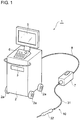
- FIG. 1 is a conceptual diagram illustrating a medical imaging system 1 for acquiring an optical coherence tomographic image.
- the medical imaging system 1 includes a console body 2, a driving device 7, and an OCT catheter 10.
- the console body 2 includes elements that realize basic functions for acquiring in vivo images, such as a light source, an optical measurement unit, a control unit, a computer that performs image calculation, and a power source.
- the console body 2 is provided with casters 2a so that the operator can move the console body 2 easily.
- the console body 2 is also provided in an upper part thereof with a drive 3 into which a recording medium is to be inserted, a monitor 5 that displays an image acquired, and input means 6, such as a keyboard or a mouse, for enabling input operation.
- the driving device 7 is a device that rotates an interior member 20 (to be described below) for a rotational scanning operation performed by the OCT catheter 10.
- the driving device 7 is connected to the console body 2 with a cable 8.
- the cable 8 includes an electric wire and an optical fiber.
- the driving device 7 is positioned away from the console body 2 but near the patient.
- the OCT catheter 10 connected to the driving device 7 includes a handpiece 32.
- the handpiece 32 is connected to the driving device 7 with a tube 31.
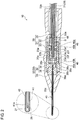
- FIG. 2 is a sectional view of the OCT catheter 10, which is based on a first embodiment of the present invention.
- the OCT catheter 10 includes the interior member 20 including a torque wire 21 and an optical fiber 25, and an outer housing 30 covering the interior member 20.
- the optical fiber 25 is a typical single-mode optical fiber and has a structure in which grass fibers including a core having a high refractive index and a cladding having a low refractive index are covered with a resin covering.
- the proximal end of the optical fiber 25 is fixed to an optical connector provided in the driving device 7, whereby the optical fiber 25 is optically connected to the console body 2 with the cable 8.
- the optical fiber 25 is also fixed to the torque wire 21 with adhesive or the like, thereby being rotatable together with the torque wire 21.
- a graded-index (GRIN) lens serving as a condensation optical system 26 and a mirror serving as a deflection optical system 27 that are fusion-spliced to each other in series.
- the condensation optical system 26 condenses light emitted from the distal end of the optical fiber 25.
- the deflection optical system 27 deflects the light emitted from the distal end of the optical fiber 25 such that the light is redirected substantially perpendicularly to the lengthwise direction of the OCT catheter.
- the lens (the condensation optical system) and the mirror (the deflection optical system) are each made of silica glass or borosilicate glass.
- the torque wire 21 includes a torque-wire body 22 and a flange portion 23 provided on the torque-wire body 22.
- the torque-wire body 22 is a metal tubular flexible member and has an inside diameter and an outside diameter that are each uniform in the lengthwise direction.
- the torque-wire body 22 envelops in a hollow portion thereof the optical fiber 25, which transmits light.
- the torque-wire body 22 transmits, to the distal end of the OCT catheter 10, a rotational force transmitted from the driving device 7 connected to the proximal end thereof.
- the flange portion 23 has a larger outside diameter than the torque-wire body 22.
- the flange portion 23 according to the first embodiment is a tubular member that is fixed to the torque-wire body 22.
- the flange portion 23 has a through hole 23a through which the torque-wire body 22 extends.
- a stepped portion 23b that is in contact with the distal end of the torque-wire body 22 is provided.
- the torque-wire body 22 and the flange portion 23 are bonded and fixed to each other with the torque-wire body 22 being in contact with the stepped portion 23b.
- the flange portion 23 according to the first embodiment is a member that is separate from the torque-wire body 22. Therefore, the flange portion 23 can be easily formed into a desired shape.
- the flange portion 23 may be made of any of various materials such as a low-friction material.
- the flange portion 23 includes a distal-end part 23c at the distal end thereof in the axial direction, and a rear-end part 23d at the rear end thereof in the axial direction.
- the flange portion 23 further includes a middle part 23e provided between the distal-end part 23c and the rear-end part 23d.
- the end faces of the distal-end part 23c and the rear-end part 23d are each a flat surface perpendicular to the axial direction.
- the outside diameters of the distal-end part 23c and the rear-end part 23d are smaller than the outside diameter of the middle part 23e.
- Projections 23f are provided between the distal-end part 23c and the middle part 23e and between the rear-end part 23d and the middle part 23e, respectively.
- the projections 23f each have an annular shape with an outside diameter larger than the outside diameter of the middle part 23e.
- the outer housing 30 includes the tube 31 and the handpiece 32.
- the tube 31 is a tubular flexible member and envelops the torque-wire body 22.
- a predetermined clearance is provided between the inner periphery of the tube 31 and the outer periphery of the torque-wire body 22.
- the torque-wire body 22 is rotatable in the tube 31.
- the tube 31 is connected to the driving device 7 at the proximal end thereof and to the handpiece 32 at the distal end thereof.
- the handpiece 32 is a portion of the OCT catheter 10 that is to be held by the user.
- the handpiece 32 includes a substantially cylindrical case body 33 that has an internal space S, and a positioning member 34 that is fixed in the internal space S and determines the position of the interior member 20 in the radial direction.
- An annular stepped portion (first stepped portion) 33a is provided in the internal space S of the case body 33.
- the stepped portion 33a projects from the inner peripheral wall of the case body 33 toward the center in the radial direction.
- the case body has at the rear end thereof a through hole 33b, in which a distal portion of the tube 31 is fitted.
- the distal end of the tube 31 extends up to the stepped portion 33a and is bonded to, for example, the inner peripheral surface of the stepped portion 33a.
- a distal portion of the torque wire 21 extends beyond the distal end of the tube 31.
- the positioning member 34 includes a first member 35 having a substantially cylindrical shape, and a second member 36 fitted to the distal end of the first member 35.
- the positioning member 34 includes a cylindrical portion 35a included in the first member 35, and a wall portion (second stepped portion) 36a included in the second member 36.
- the wall portion 36a and the stepped portion 33a face each other in the lengthwise direction of the interior member 20 in the internal space S of the handpiece 32.
- the wall portion 36a is provided on a side of the cylindrical portion 35a that is nearer to the distal end of the cylindrical portion 35a, and extends radially inward from the inner peripheral surface of the cylindrical portion 35a.
- the wall portion 36a has in the radial center thereof a through hole 36b through which the optical fiber 25 extends.
- the rear end of the wall portion 36a forms an end face 36c that is exposed in the cylindrical portion 35a.
- the second member 36 is in engagement with a projected portion 35b included in the first member 35 and extending toward the radial center.
- the projected portion 35b has a through hole 35c communicating with the through hole 36b.
- a needle 40 is fixed at the distal end of the through hole 36b provided in the second member 36.
- the needle 40 is exposed to the outside from a through hole 33c provided at the distal end of the case body 33.
- the needle 40 includes a tubular needle body 41 made of, for example, stainless steel, and a resin covering member 42 covering the needle body 41.
- the needle body 41 envelops a distal portion of the optical fiber 25 such that the distal portion is rotatable therein.
- the needle body 41 has a slit 41a at the distal end thereof. Hence, the light from the optical fiber 25 is allowed to emerge to the outside.
- the flange portion 23 of the torque wire 21 is positioned on the inner side of the cylindrical portion 35a and between the wall portion 36a and the stepped portion 33a.
- the inside diameter of the cylindrical portion 35a and the outside diameter of the projections 23fof the flange portion 23 are substantially the same.
- the flange portion 23 is rotatable on the inner side of the cylindrical portion 35a with the radial position thereof being fixed.
- a bearing (friction-reducing portion) 45 is provided on the inner side of the cylindrical portion 35a and between the wall portion 36a and the flange portion 23.
- the bearing 45 includes an outer race 45a and an inner race 45b provided on the inner side of the outer race 45a.
- Rotating bodies such as balls, which are not illustrated, are provided between the inner race 45b and the outer race 45a, whereby the inner race 45b is rotatable relative to the outer race 45a.
- only the outer race 45a faces toward the wall portion 36a (the end face 36c), whereas the inner race 45b faces toward the flange portion 23.
- the outside diameter of the inner race 45b is larger than the outside diameter of the distal-end part 23c of the flange portion 23.
- the distal-end part 23c is in contact with only the inner race 45b and is out of contact with the outer race 45a.
- the inside diameter of the cylindrical portion 35a and the outside diameter of the bearing 45 are substantially the same, whereby the bearing 45 is movable in the front-rear direction on the inner side of the cylindrical portion 35a.
- the optical fiber 25 extends on the inner side of the inner race 45b of the bearing 45.
- Another bearing (friction-reducing portion) 46 is provided on the inner side of the cylindrical portion 35a and between the stepped portion 33a and the flange portion 23.
- the bearing 46 has the same configuration as the bearing 45 and includes an outer race 46a and an inner race 46b. Only the outer race 46a faces toward the stepped portion 33a, whereas the inner race 46b faces toward the flange portion 23.
- the outside diameter of the inner race 46b is larger than the outside diameter of the rear-end part 23d of the flange portion 23. Therefore, the rear-end part 23d of the flange portion 23 is in contact with only the inner race 46b and is out of contact with the outer race 46a.
- An elastic member is provided between the bearing 46 and the stepped portion 33a (that is, the bearing 46 and the elastic member are provided between the stepped portion 33a and the flange portion 23).
- a coil spring 48 is employed as the elastic member.
- the coil spring 48 has a natural length that is longer than a length obtained by subtracting the total length of the bearing 45, the flange portion 23, and the bearing 46 in the front-rear direction from the distance between the wall portion 36a (specifically, the end face 36c) and the stepped portion 33a. Therefore, in a state where the bearing 45, the flange portion 23, the bearing 46, and the coil spring 48 are placed on the inner side of the cylindrical portion 35a, the coil spring 48 presses the bearing 45, the flange portion 23, and the bearing 46 toward the wall portion 36a.
- the flange portion 23 is pressed in a direction from the stepped portion 33a toward the wall portion 36a by the coil spring 48.
- the position of the flange portion 23 in the lengthwise direction of the torque wire 21 is controlled. That is, if the flange portion 23 receives an external force acting in a direction toward the stepped portion 33a, the movement of the flange portion 23 is regulated by the elastic force (urging force) exerted by the coil spring 48.
- the flange portion receives external force acting in a direction toward the wall portion 36a, the movement of the flange portion 23 is regulated by the wall portion 36a.
- the flange portion 23 is provided on the torque wire 21. Therefore, regulating the movement of the flange portion 23 regulates the movements of the torque wire 21 and the optical fiber 25.
- the interior member 20 is rotated at a high speed by the driving device 7. If the interior member 20 is moved in the front-rear direction in the outer housing with vibrations or the like caused by such a rotation, the position of the optical fiber becomes instable, making it difficult to acquire an accurate optical coherence tomographic image.
- the movement of the interior member 20 in the front-rear direction in the outer housing 30 can be suppressed. Therefore, the position of the optical fiber 25 in the needle 40 is kept stable.
- the tube 31 and the torque-wire body 22 are arranged with a predetermined clearance interposed therebetween so that the rotation of the interior member 20 is not hindered. Therefore, depending on the state of the tube 31, for example, in a case where the tube 31 is rolled up with a small diameter, the torque-wire body 22 may be pulled in the tube 31 toward the driving device 7, and an excessive load may be applied to the interior member 20.
- the flange portion 23 is pressed toward the distal side by the coil spring 48. Therefore, even if the interior member 20 is pulled toward the proximal side, the coil spring 48 is compressed and thus prevents the interior member 20 from receiving an excessive load. Furthermore, when the interior member 20 that has been pulled is released, the interior member 20 is caused to return to the initial position by the coil spring 48.
- the bearings 45 and 46 are provided as the friction-reducing portions, the rotation of the flange portion 23 on the torque wire 21 is not hindered. Moreover, since the bearings 45 and 46 are employed as the friction-reducing portions, friction can be reduced efficiently.
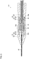
- An OCT catheter 110 according to a second embodiment differs from the OCT catheter 10 according to the first embodiment in the position of the coil spring 48 serving as the elastic member. Now, such differences from the first embodiment will be described mainly. Elements and members that are identical to those described above are denoted by corresponding ones of the reference numerals, and detailed description of such elements and members is omitted.
- the OCT catheter 110 includes the interior member 20 including the optical fiber 25, the torque-wire body 22, and the flange portion 23; the outer housing 30 covering the interior member 20; and the needle 40.
- the OCT catheter 110 further includes the bearings 45 and 46 and the coil spring 48 that are provided on the inner side of the cylindrical portion 35a of the first member 35 included in the outer housing 30.
- the coil spring 48 is provided between the wall portion (first stepped portion) 36a and the flange portion 23, and the bearing 45 is provided between the coil spring 48 and the flange portion 23. Furthermore, the bearing 46 is provided between the stepped portion (second stepped portion) 33a and the flange portion 23. Therefore, in a state where the coil spring 48, the bearing 45, the flange portion 23, and the bearing 46 are placed on the inner side of the cylindrical portion 35a, the coil spring 48 presses the bearing 45, the flange portion 23, and the bearing 46 toward the stepped portion 33a. Hence, the position of the interior member 20 in the front-rear direction in the outer housing 30 is regulated. Consequently, the position of the optical fiber 25 in the needle 40 is kept stable.
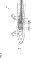
- An OCT catheter 210 according to a third embodiment differs from the OCT catheter 10 according to the first embodiment in the configuration of a flange portion 223 provided on the torque-wire body 22. Now, such differences from the first embodiment will be described mainly. Elements and members that are identical to those described above are denoted by corresponding ones of the reference numerals, and detailed description of such elements and members is omitted.
- the OCT catheter 210 includes an interior member 220 including the optical fiber 25 and a torque wire 221; the outer housing 30 covering the interior member 220; and the needle 40.
- the OCT catheter 210 further includes the bearings 45 and 46 and the coil spring 48 that are provided on the inner side of the cylindrical portion 35a of the first member 35 included in the outer housing 30.
- the arrangement of the bearings 45 and 46 and the coil spring 48 is the same as in the first embodiment.
- the torque wire 221 includes the torque-wire body 22 and the flange portion 223.
- the flange portion 223 forms a thick portion of the torque wire 221 and is provided at the distal end of the torque-wire body 22.
- the outside diameter of the flange portion 223 is smaller than the outside diameters of the inner races 45b and 46b of the respective bearings 45 and 46. Therefore, the front end and the rear end of the flange portion 223 are out of contact with the outer races 45a and 46a but are in contact with the inner races 45b and 46b. Therefore, as in the first embodiment, the position of the interior member 220 in the front-rear direction in the outer housing 30 is regulated. Consequently, the position of the optical fiber 25 in the needle 40 is kept stable. Since the thick portion of the torque wire 221 serves as the flange portion 223, the number of components can be reduced, which is advantageous in terms of cost and reliability.
- each friction-reducing portion only needs to be capable of reducing the friction occurring between the flange portion and each of the wall portion 36a, the stepped portion 33a, and the coil spring 48 and may be, for example, a so-called unlubricated bush or the like.
- the elastic member only needs to be configured to press the flange portion toward the wall portion 36a or toward the stepped portion 33a and may be, for example, a rubber member or the like having a predetermined elasticity.
- some of the features of different embodiments may be combined together.
- the flange portion 23 according to the second embodiment may be replaced with the flange portion 223 according to the third embodiment.
Landscapes
- Health & Medical Sciences (AREA)
- Life Sciences & Earth Sciences (AREA)
- General Health & Medical Sciences (AREA)
- Biophysics (AREA)
- Engineering & Computer Science (AREA)
- Veterinary Medicine (AREA)
- Biomedical Technology (AREA)
- Heart & Thoracic Surgery (AREA)
- Public Health (AREA)
- Animal Behavior & Ethology (AREA)
- Medical Informatics (AREA)
- Physics & Mathematics (AREA)
- Pathology (AREA)
- Molecular Biology (AREA)
- Surgery (AREA)
- Nuclear Medicine, Radiotherapy & Molecular Imaging (AREA)
- Radiology & Medical Imaging (AREA)
- Hematology (AREA)
- Anesthesiology (AREA)
- Pulmonology (AREA)
- Endoscopes (AREA)
- Instruments For Viewing The Inside Of Hollow Bodies (AREA)
Abstract
Description
- This application claims the benefit of Japanese Patent Application No.
2015-196521 filed October 2, 2015 - The present invention relates an OCT catheter.
- Optical coherence tomography (OCT) catheters for acquiring in vivo optical coherence tomographic images are known. For example, a catheter disclosed by Japanese Unexamined Patent Application Publication No.
2013-202295 - In general, an OCT catheter that is to be inserted into a blood vessel is used for acquiring an optical coherence tomographic image in a predetermined lengthwise range of an outer housing, such as the jacket tube, while a condensation-deflection optical system is moved backward (pulled backward) relative to the outer housing. Hence, in such an OCT catheter, the condensation-deflection optical system is movable in the lengthwise direction of the outer housing. However, to acquire an optical coherence tomographic image at a fixed position in a situation such as a fundus examination, the condensation-deflection optical system needs to be set stationary at that position.
- Moreover, there is typically a clearance between an interior member, such as the condensation-deflection optical system, and the outer housing so that the rotation of the interior member is not hindered by the outer housing. Therefore, depending on the state of use, the interior member may move in the front-rear direction in the outer housing.
- The present invention provides an OCT catheter configured such that the movement of an interior member in the front-rear direction in an outer housing is suppressed.
- An OCT catheter according to the present invention includes an interior member including a tubular torque wire and an optical fiber, the torque wire including a torque-wire body and a flange provided on the torque-wire body, the torque wire transmitting rotation from a proximal end toward a distal end, the optical fiber being enveloped by the torque wire and transmitting light; an outer housing including a first stepped portion and a second stepped portion that face each other across the flange, the outer housing covering the interior member; and an elastic member provided between the first stepped portion and the flange portion and pressing the flange toward the second stepped portion.
- A friction-reducing portion may be provided between the elastic member and the flange portion. Likewise, a friction-reducing portion may be provided between the second stepped portion and the flange portion. The friction-reducing portion may be a bearing. The second stepped portion may be positioned nearer to the distal end than the first stepped portion in a lengthwise direction. The flange portion may be a tubular member fixed to the torque-wire body or a thick portion of the torque wire.
- In the OCT catheter according to the present invention, the movement of the interior member in the front-rear direction in the outer housing can be suppressed.
-
-
Figure 1 is a conceptual diagram illustrating an OCT apparatus including an OCT catheter. -
Figure 2 is a sectional view of an OCT catheter according to a first embodiment of the present invention. -
Figure 3 is a sectional view of an OCT catheter according to a second embodiment of the present invention. -
Figure 4 is a sectional view of an OCT catheter according to a third embodiment of the present invention. - Embodiments of the present invention will now be described specifically with reference to the drawings. As a matter of convenience, elements that are substantially identical are denoted by the same reference numerals, and description of such elements may be omitted. In the following description, the lengthwise direction of the OCT catheter is also referred to as the front-rear direction, with the proximal side defined as the rear side and the distal side defined as the front side.
-
Figure 1 is a conceptual diagram illustrating amedical imaging system 1 for acquiring an optical coherence tomographic image. Themedical imaging system 1 includes aconsole body 2, adriving device 7, and anOCT catheter 10. - The
console body 2 includes elements that realize basic functions for acquiring in vivo images, such as a light source, an optical measurement unit, a control unit, a computer that performs image calculation, and a power source. Theconsole body 2 is provided withcasters 2a so that the operator can move theconsole body 2 easily. Theconsole body 2 is also provided in an upper part thereof with adrive 3 into which a recording medium is to be inserted, amonitor 5 that displays an image acquired, and input means 6, such as a keyboard or a mouse, for enabling input operation. - The
driving device 7 is a device that rotates an interior member 20 (to be described below) for a rotational scanning operation performed by theOCT catheter 10. Thedriving device 7 is connected to theconsole body 2 with acable 8. Thecable 8 includes an electric wire and an optical fiber. Thedriving device 7 is positioned away from theconsole body 2 but near the patient. TheOCT catheter 10 connected to thedriving device 7 includes ahandpiece 32. Thehandpiece 32 is connected to thedriving device 7 with atube 31. -
Figure 2 is a sectional view of theOCT catheter 10, which is based on a first embodiment of the present invention. As illustrated inFigure 2 , theOCT catheter 10 includes theinterior member 20 including atorque wire 21 and anoptical fiber 25, and anouter housing 30 covering theinterior member 20. Theoptical fiber 25 is a typical single-mode optical fiber and has a structure in which grass fibers including a core having a high refractive index and a cladding having a low refractive index are covered with a resin covering. The proximal end of theoptical fiber 25 is fixed to an optical connector provided in thedriving device 7, whereby theoptical fiber 25 is optically connected to theconsole body 2 with thecable 8. Theoptical fiber 25 is also fixed to thetorque wire 21 with adhesive or the like, thereby being rotatable together with thetorque wire 21. - At the distal end of the
optical fiber 25, provided are a graded-index (GRIN) lens serving as a condensationoptical system 26 and a mirror serving as a deflectionoptical system 27 that are fusion-spliced to each other in series. The condensationoptical system 26 condenses light emitted from the distal end of theoptical fiber 25. The deflectionoptical system 27 deflects the light emitted from the distal end of theoptical fiber 25 such that the light is redirected substantially perpendicularly to the lengthwise direction of the OCT catheter. The lens (the condensation optical system) and the mirror (the deflection optical system) are each made of silica glass or borosilicate glass. - The
torque wire 21 includes a torque-wire body 22 and aflange portion 23 provided on the torque-wire body 22. The torque-wire body 22 is a metal tubular flexible member and has an inside diameter and an outside diameter that are each uniform in the lengthwise direction. The torque-wire body 22 envelops in a hollow portion thereof theoptical fiber 25, which transmits light. The torque-wire body 22 transmits, to the distal end of theOCT catheter 10, a rotational force transmitted from thedriving device 7 connected to the proximal end thereof. - The
flange portion 23 has a larger outside diameter than the torque-wire body 22. Theflange portion 23 according to the first embodiment is a tubular member that is fixed to the torque-wire body 22. Theflange portion 23 has a throughhole 23a through which the torque-wire body 22 extends. At the distal end of the throughhole 23a, a steppedportion 23b that is in contact with the distal end of the torque-wire body 22 is provided. The torque-wire body 22 and theflange portion 23 are bonded and fixed to each other with the torque-wire body 22 being in contact with thestepped portion 23b. Theflange portion 23 according to the first embodiment is a member that is separate from the torque-wire body 22. Therefore, theflange portion 23 can be easily formed into a desired shape. Moreover, theflange portion 23 may be made of any of various materials such as a low-friction material. - The
flange portion 23 includes a distal-end part 23c at the distal end thereof in the axial direction, and a rear-end part 23d at the rear end thereof in the axial direction. Theflange portion 23 further includes amiddle part 23e provided between the distal-end part 23c and the rear-end part 23d. The end faces of the distal-end part 23c and the rear-end part 23d are each a flat surface perpendicular to the axial direction. The outside diameters of the distal-end part 23c and the rear-end part 23d are smaller than the outside diameter of themiddle part 23e.Projections 23f are provided between the distal-end part 23c and themiddle part 23e and between the rear-end part 23d and themiddle part 23e, respectively. Theprojections 23f each have an annular shape with an outside diameter larger than the outside diameter of themiddle part 23e. - The
outer housing 30 includes thetube 31 and thehandpiece 32. Thetube 31 is a tubular flexible member and envelops the torque-wire body 22. A predetermined clearance is provided between the inner periphery of thetube 31 and the outer periphery of the torque-wire body 22. Hence, the torque-wire body 22 is rotatable in thetube 31. Thetube 31 is connected to thedriving device 7 at the proximal end thereof and to thehandpiece 32 at the distal end thereof. - The
handpiece 32 is a portion of theOCT catheter 10 that is to be held by the user. Thehandpiece 32 includes a substantiallycylindrical case body 33 that has an internal space S, and a positioningmember 34 that is fixed in the internal space S and determines the position of theinterior member 20 in the radial direction. An annular stepped portion (first stepped portion) 33a is provided in the internal space S of thecase body 33. The steppedportion 33a projects from the inner peripheral wall of thecase body 33 toward the center in the radial direction. The case body has at the rear end thereof a throughhole 33b, in which a distal portion of thetube 31 is fitted. The distal end of thetube 31 extends up to the steppedportion 33a and is bonded to, for example, the inner peripheral surface of the steppedportion 33a. A distal portion of thetorque wire 21 extends beyond the distal end of thetube 31. - The positioning
member 34 includes afirst member 35 having a substantially cylindrical shape, and asecond member 36 fitted to the distal end of thefirst member 35. Specifically, the positioningmember 34 includes acylindrical portion 35a included in thefirst member 35, and a wall portion (second stepped portion) 36a included in thesecond member 36. Thewall portion 36a and the steppedportion 33a face each other in the lengthwise direction of theinterior member 20 in the internal space S of thehandpiece 32. Thewall portion 36a is provided on a side of thecylindrical portion 35a that is nearer to the distal end of thecylindrical portion 35a, and extends radially inward from the inner peripheral surface of thecylindrical portion 35a. Thewall portion 36a has in the radial center thereof a through hole 36b through which theoptical fiber 25 extends. The rear end of thewall portion 36a forms an end face 36c that is exposed in thecylindrical portion 35a. In the first embodiment, thesecond member 36 is in engagement with a projectedportion 35b included in thefirst member 35 and extending toward the radial center. The projectedportion 35b has a throughhole 35c communicating with the through hole 36b. - A
needle 40 is fixed at the distal end of the through hole 36b provided in thesecond member 36. Theneedle 40 is exposed to the outside from a throughhole 33c provided at the distal end of thecase body 33. Theneedle 40 includes atubular needle body 41 made of, for example, stainless steel, and aresin covering member 42 covering theneedle body 41. Theneedle body 41 envelops a distal portion of theoptical fiber 25 such that the distal portion is rotatable therein. Theneedle body 41 has aslit 41a at the distal end thereof. Hence, the light from theoptical fiber 25 is allowed to emerge to the outside. - The
flange portion 23 of thetorque wire 21 is positioned on the inner side of thecylindrical portion 35a and between thewall portion 36a and the steppedportion 33a. The inside diameter of thecylindrical portion 35a and the outside diameter of the projections 23fof theflange portion 23 are substantially the same. Hence, theflange portion 23 is rotatable on the inner side of thecylindrical portion 35a with the radial position thereof being fixed. - A bearing (friction-reducing portion) 45 is provided on the inner side of the
cylindrical portion 35a and between thewall portion 36a and theflange portion 23. Thebearing 45 includes anouter race 45a and aninner race 45b provided on the inner side of theouter race 45a. Rotating bodies such as balls, which are not illustrated, are provided between theinner race 45b and theouter race 45a, whereby theinner race 45b is rotatable relative to theouter race 45a. According to the first embodiment, only theouter race 45a faces toward thewall portion 36a (the end face 36c), whereas theinner race 45b faces toward theflange portion 23. The outside diameter of theinner race 45b is larger than the outside diameter of the distal-end part 23c of theflange portion 23. Hence, the distal-end part 23c is in contact with only theinner race 45b and is out of contact with theouter race 45a. The inside diameter of thecylindrical portion 35a and the outside diameter of thebearing 45 are substantially the same, whereby thebearing 45 is movable in the front-rear direction on the inner side of thecylindrical portion 35a. Theoptical fiber 25 extends on the inner side of theinner race 45b of thebearing 45. - Another bearing (friction-reducing portion) 46 is provided on the inner side of the
cylindrical portion 35a and between the steppedportion 33a and theflange portion 23. Thebearing 46 has the same configuration as thebearing 45 and includes anouter race 46a and aninner race 46b. Only theouter race 46a faces toward the steppedportion 33a, whereas theinner race 46b faces toward theflange portion 23. The outside diameter of theinner race 46b is larger than the outside diameter of the rear-end part 23d of theflange portion 23. Therefore, the rear-end part 23d of theflange portion 23 is in contact with only theinner race 46b and is out of contact with theouter race 46a. An elastic member is provided between the bearing 46 and the steppedportion 33a (that is, thebearing 46 and the elastic member are provided between the steppedportion 33a and the flange portion 23). In the first embodiment, acoil spring 48 is employed as the elastic member. - The
coil spring 48 has a natural length that is longer than a length obtained by subtracting the total length of thebearing 45, theflange portion 23, and thebearing 46 in the front-rear direction from the distance between thewall portion 36a (specifically, the end face 36c) and the steppedportion 33a. Therefore, in a state where thebearing 45, theflange portion 23, thebearing 46, and thecoil spring 48 are placed on the inner side of thecylindrical portion 35a, thecoil spring 48 presses thebearing 45, theflange portion 23, and thebearing 46 toward thewall portion 36a. - In the
OCT catheter 10 described above, theflange portion 23 is pressed in a direction from the steppedportion 33a toward thewall portion 36a by thecoil spring 48. Thus, the position of theflange portion 23 in the lengthwise direction of thetorque wire 21 is controlled. That is, if theflange portion 23 receives an external force acting in a direction toward the steppedportion 33a, the movement of theflange portion 23 is regulated by the elastic force (urging force) exerted by thecoil spring 48. On the other hand, if the flange portion receives external force acting in a direction toward thewall portion 36a, the movement of theflange portion 23 is regulated by thewall portion 36a. Theflange portion 23 is provided on thetorque wire 21. Therefore, regulating the movement of theflange portion 23 regulates the movements of thetorque wire 21 and theoptical fiber 25. - During a measurement performed by the
medical imaging system 1, theinterior member 20 is rotated at a high speed by the drivingdevice 7. If theinterior member 20 is moved in the front-rear direction in the outer housing with vibrations or the like caused by such a rotation, the position of the optical fiber becomes instable, making it difficult to acquire an accurate optical coherence tomographic image. According to the first embodiment, the movement of theinterior member 20 in the front-rear direction in theouter housing 30 can be suppressed. Therefore, the position of theoptical fiber 25 in theneedle 40 is kept stable. - The
tube 31 and the torque-wire body 22 are arranged with a predetermined clearance interposed therebetween so that the rotation of theinterior member 20 is not hindered. Therefore, depending on the state of thetube 31, for example, in a case where thetube 31 is rolled up with a small diameter, the torque-wire body 22 may be pulled in thetube 31 toward thedriving device 7, and an excessive load may be applied to theinterior member 20. In contrast, according to the first embodiment, theflange portion 23 is pressed toward the distal side by thecoil spring 48. Therefore, even if theinterior member 20 is pulled toward the proximal side, thecoil spring 48 is compressed and thus prevents theinterior member 20 from receiving an excessive load. Furthermore, when theinterior member 20 that has been pulled is released, theinterior member 20 is caused to return to the initial position by thecoil spring 48. - Furthermore, since the
bearings flange portion 23 on thetorque wire 21 is not hindered. Moreover, since thebearings - An
OCT catheter 110 according to a second embodiment differs from theOCT catheter 10 according to the first embodiment in the position of thecoil spring 48 serving as the elastic member. Now, such differences from the first embodiment will be described mainly. Elements and members that are identical to those described above are denoted by corresponding ones of the reference numerals, and detailed description of such elements and members is omitted. - As illustrated in
Figure 3 , theOCT catheter 110 includes theinterior member 20 including theoptical fiber 25, the torque-wire body 22, and theflange portion 23; theouter housing 30 covering theinterior member 20; and theneedle 40. TheOCT catheter 110 further includes thebearings coil spring 48 that are provided on the inner side of thecylindrical portion 35a of thefirst member 35 included in theouter housing 30. - According to the second embodiment, the
coil spring 48 is provided between the wall portion (first stepped portion) 36a and theflange portion 23, and thebearing 45 is provided between thecoil spring 48 and theflange portion 23. Furthermore, thebearing 46 is provided between the stepped portion (second stepped portion) 33a and theflange portion 23. Therefore, in a state where thecoil spring 48, thebearing 45, theflange portion 23, and thebearing 46 are placed on the inner side of thecylindrical portion 35a, thecoil spring 48 presses thebearing 45, theflange portion 23, and thebearing 46 toward the steppedportion 33a. Hence, the position of theinterior member 20 in the front-rear direction in theouter housing 30 is regulated. Consequently, the position of theoptical fiber 25 in theneedle 40 is kept stable. - An
OCT catheter 210 according to a third embodiment differs from theOCT catheter 10 according to the first embodiment in the configuration of aflange portion 223 provided on the torque-wire body 22. Now, such differences from the first embodiment will be described mainly. Elements and members that are identical to those described above are denoted by corresponding ones of the reference numerals, and detailed description of such elements and members is omitted. - As illustrated in
Figure 4 , theOCT catheter 210 includes aninterior member 220 including theoptical fiber 25 and atorque wire 221; theouter housing 30 covering theinterior member 220; and theneedle 40. TheOCT catheter 210 further includes thebearings coil spring 48 that are provided on the inner side of thecylindrical portion 35a of thefirst member 35 included in theouter housing 30. The arrangement of thebearings coil spring 48 is the same as in the first embodiment. - The
torque wire 221 includes the torque-wire body 22 and theflange portion 223. According to the third embodiment, theflange portion 223 forms a thick portion of thetorque wire 221 and is provided at the distal end of the torque-wire body 22. The outside diameter of theflange portion 223 is smaller than the outside diameters of theinner races respective bearings flange portion 223 are out of contact with theouter races inner races interior member 220 in the front-rear direction in theouter housing 30 is regulated. Consequently, the position of theoptical fiber 25 in theneedle 40 is kept stable. Since the thick portion of thetorque wire 221 serves as theflange portion 223, the number of components can be reduced, which is advantageous in terms of cost and reliability. - While some embodiments of the present invention have been described above with reference to the drawings, the specific configuration is not limited to such embodiments. For example, each friction-reducing portion only needs to be capable of reducing the friction occurring between the flange portion and each of the
wall portion 36a, the steppedportion 33a, and thecoil spring 48 and may be, for example, a so-called unlubricated bush or the like. Furthermore, the elastic member only needs to be configured to press the flange portion toward thewall portion 36a or toward the steppedportion 33a and may be, for example, a rubber member or the like having a predetermined elasticity. Moreover, some of the features of different embodiments may be combined together. For example, theflange portion 23 according to the second embodiment may be replaced with theflange portion 223 according to the third embodiment.
Claims (7)
- An OCT catheter comprising:an interior member including a tubular torque wire and an optical fiber, the torque wire including a torque-wire body and a flange provided on the torque-wire body, the torque wire transmitting rotation from a proximal end toward a distal end, the optical fiber being enveloped by the torque wire and transmitting light;an outer housing including a first stepped portion and a second stepped portion that face each other across the flange, the outer housing covering the interior member; andan elastic member provided between the first stepped portion and the flange and pressing the flange toward the second stepped portion.
- The OCT catheter according to Claim 1,
wherein a friction-reducing portion is provided between the elastic member and the flange. - The OCT catheter according to Claim 1 or 2,
wherein a friction-reducing portion is provided between the second stepped portion and the flange. - The OCT catheter according to Claim 2 or 3,
wherein the friction-reducing portion is a bearing. - The OCT catheter according to any of Claims 1 to 4,
wherein the second stepped portion is positioned nearer to the distal end than the first stepped portion. - The OCT catheter according to any of Claims 1 to 5,
wherein the flange is a tubular member fixed to the torque-wire body. - The OCT catheter according to any of Claims 1 to 5,
wherein the flange is a thick portion of the torque wire.
Applications Claiming Priority (2)
| Application Number | Priority Date | Filing Date | Title |
|---|---|---|---|
| JP2015196521A JP2017064293A (en) | 2015-10-02 | 2015-10-02 | OCT catheter |
| PCT/JP2016/070671 WO2017056637A1 (en) | 2015-10-02 | 2016-07-13 | Oct catheter |
Publications (2)
| Publication Number | Publication Date |
|---|---|
| EP3357401A1 true EP3357401A1 (en) | 2018-08-08 |
| EP3357401A4 EP3357401A4 (en) | 2018-10-31 |
Family
ID=58427441
Family Applications (1)
| Application Number | Title | Priority Date | Filing Date |
|---|---|---|---|
| EP16850814.1A Withdrawn EP3357401A4 (en) | 2015-10-02 | 2016-07-13 | Oct catheter |
Country Status (4)
| Country | Link |
|---|---|
| US (1) | US20180263499A1 (en) |
| EP (1) | EP3357401A4 (en) |
| JP (1) | JP2017064293A (en) |
| WO (1) | WO2017056637A1 (en) |
Families Citing this family (3)
| Publication number | Priority date | Publication date | Assignee | Title |
|---|---|---|---|---|
| EP3917376A4 (en) | 2019-02-01 | 2022-11-16 | The Johns Hopkins University | LAYER BOUNDARY EVOLUTION FOR MACULAR OPTICAL COHERENCE TOMOGRAPHY SEGMENTATION |
| KR102786855B1 (en) | 2024-04-11 | 2025-03-26 | 주식회사 에이치와이티씨 | Torsional Ultrasonic Vibration Transducer |
| KR102755244B1 (en) | 2024-07-08 | 2025-01-21 | 주식회사 에이치와이티씨 | Ultrasonic Composite Vibration Transducer |
Family Cites Families (5)
| Publication number | Priority date | Publication date | Assignee | Title |
|---|---|---|---|---|
| US5872879A (en) * | 1996-11-25 | 1999-02-16 | Boston Scientific Corporation | Rotatable connecting optical fibers |
| US7180600B2 (en) * | 1998-09-21 | 2007-02-20 | Olympus Corporation | Optical imaging apparatus |
| JP2001079007A (en) * | 1999-09-13 | 2001-03-27 | Olympus Optical Co Ltd | Optical probe device |
| JP5001261B2 (en) * | 2005-05-04 | 2012-08-15 | フルイド メディカル,インコーポレイテッド | Small actuator mechanism for intravascular imaging |
| JP2012217588A (en) * | 2011-04-07 | 2012-11-12 | Terumo Corp | Medical device |
-
2015
- 2015-10-02 JP JP2015196521A patent/JP2017064293A/en not_active Withdrawn
-
2016
- 2016-07-13 EP EP16850814.1A patent/EP3357401A4/en not_active Withdrawn
- 2016-07-13 WO PCT/JP2016/070671 patent/WO2017056637A1/en not_active Ceased
- 2016-07-13 US US15/756,847 patent/US20180263499A1/en not_active Abandoned
Also Published As
| Publication number | Publication date |
|---|---|
| EP3357401A4 (en) | 2018-10-31 |
| JP2017064293A (en) | 2017-04-06 |
| WO2017056637A1 (en) | 2017-04-06 |
| US20180263499A1 (en) | 2018-09-20 |
Similar Documents
| Publication | Publication Date | Title |
|---|---|---|
| US6749344B2 (en) | Connection apparatus for optical coherence tomography catheters | |
| US9574870B2 (en) | Probe for optical imaging | |
| JP4708937B2 (en) | OCT observation instrument, fixing instrument, and OCT system | |
| KR101731728B1 (en) | Apparatus and method for high-speed scanning device of coronary artery | |
| JP5150725B2 (en) | Connection device and optical imaging device | |
| WO2013033490A1 (en) | Rotational imaging systems with stabilizers | |
| US20180263499A1 (en) | Oct catheter | |
| US20240108210A1 (en) | Imaging Guidewire Having Telescopically Movable Imaging Core | |
| Wurster et al. | Endoscopic optical coherence tomography angiography using a forward imaging piezo scanner probe | |
| WO1998023984A2 (en) | Apparatus for rotatably connecting optical fibers | |
| JP5689721B2 (en) | Motor drive device and optical diagnostic imaging device | |
| CN104955372B (en) | probe for optical imaging | |
| US12357163B2 (en) | Catheter motor drive unit that facilitates combined optical coherence tomography and fluorescence-lifetime imaging | |
| WO2010113374A1 (en) | Light transmission device | |
| EP4654880A2 (en) | An endoscope device and imaging method for intraoperative imaging of the cochlea and imaging-guided cochlear implantation | |
| JP2015008995A (en) | Optical imaging probe | |
| CN105007796A (en) | Probe for optical imaging | |
| JPWO2015060114A1 (en) | Optical imaging probe | |
| Yan et al. | Design and evaluation of a flexible sensorized robotic OCT neuroendoscope | |
| JP2015029567A (en) | Optical imaging probe | |
| JP2016137012A (en) | catheter | |
| JP4708936B2 (en) | OCT observation instrument and OCT system | |
| JP2009077843A (en) | Optical scanning probe | |
| JP7520132B2 (en) | Optical probe and optical tomography apparatus including same | |
| JP6400586B2 (en) | Guide wire |
Legal Events
| Date | Code | Title | Description |
|---|---|---|---|
| STAA | Information on the status of an ep patent application or granted ep patent |
Free format text: STATUS: THE INTERNATIONAL PUBLICATION HAS BEEN MADE |
|
| PUAI | Public reference made under article 153(3) epc to a published international application that has entered the european phase |
Free format text: ORIGINAL CODE: 0009012 |
|
| STAA | Information on the status of an ep patent application or granted ep patent |
Free format text: STATUS: REQUEST FOR EXAMINATION WAS MADE |
|
| 17P | Request for examination filed |
Effective date: 20180301 |
|
| AK | Designated contracting states |
Kind code of ref document: A1 Designated state(s): AL AT BE BG CH CY CZ DE DK EE ES FI FR GB GR HR HU IE IS IT LI LT LU LV MC MK MT NL NO PL PT RO RS SE SI SK SM TR |
|
| AX | Request for extension of the european patent |
Extension state: BA ME |
|
| RIC1 | Information provided on ipc code assigned before grant |
Ipc: A61B 5/00 20060101ALI20180919BHEP Ipc: A61B 1/00 20060101AFI20180919BHEP |
|
| A4 | Supplementary search report drawn up and despatched |
Effective date: 20180927 |
|
| DAV | Request for validation of the european patent (deleted) | ||
| DAX | Request for extension of the european patent (deleted) | ||
| STAA | Information on the status of an ep patent application or granted ep patent |
Free format text: STATUS: THE APPLICATION IS DEEMED TO BE WITHDRAWN |
|
| 18D | Application deemed to be withdrawn |
Effective date: 20190427 |