EP3357128B1 - Coaxial electrical interconnect - Google Patents
Coaxial electrical interconnect Download PDFInfo
- Publication number
- EP3357128B1 EP3357128B1 EP16738974.1A EP16738974A EP3357128B1 EP 3357128 B1 EP3357128 B1 EP 3357128B1 EP 16738974 A EP16738974 A EP 16738974A EP 3357128 B1 EP3357128 B1 EP 3357128B1
- Authority
- EP
- European Patent Office
- Prior art keywords
- spring
- electrical interconnect
- probes
- spring probe
- plunger
- Prior art date
- Legal status (The legal status is an assumption and is not a legal conclusion. Google has not performed a legal analysis and makes no representation as to the accuracy of the status listed.)
- Active
Links
Images




Classifications
-
- H—ELECTRICITY
- H01—ELECTRIC ELEMENTS
- H01R—ELECTRICALLY-CONDUCTIVE CONNECTIONS; STRUCTURAL ASSOCIATIONS OF A PLURALITY OF MUTUALLY-INSULATED ELECTRICAL CONNECTING ELEMENTS; COUPLING DEVICES; CURRENT COLLECTORS
- H01R31/00—Coupling parts supported only by co-operation with counterpart
- H01R31/06—Intermediate parts for linking two coupling parts, e.g. adapter
-
- H—ELECTRICITY
- H01—ELECTRIC ELEMENTS
- H01R—ELECTRICALLY-CONDUCTIVE CONNECTIONS; STRUCTURAL ASSOCIATIONS OF A PLURALITY OF MUTUALLY-INSULATED ELECTRICAL CONNECTING ELEMENTS; COUPLING DEVICES; CURRENT COLLECTORS
- H01R12/00—Structural associations of a plurality of mutually-insulated electrical connecting elements, specially adapted for printed circuits, e.g. printed circuit boards [PCB], flat or ribbon cables, or like generally planar structures, e.g. terminal strips, terminal blocks; Coupling devices specially adapted for printed circuits, flat or ribbon cables, or like generally planar structures; Terminals specially adapted for contact with, or insertion into, printed circuits, flat or ribbon cables, or like generally planar structures
- H01R12/70—Coupling devices
- H01R12/71—Coupling devices for rigid printing circuits or like structures
- H01R12/712—Coupling devices for rigid printing circuits or like structures co-operating with the surface of the printed circuit or with a coupling device exclusively provided on the surface of the printed circuit
- H01R12/714—Coupling devices for rigid printing circuits or like structures co-operating with the surface of the printed circuit or with a coupling device exclusively provided on the surface of the printed circuit with contacts abutting directly the printed circuit; Button contacts therefore provided on the printed circuit
-
- H—ELECTRICITY
- H01—ELECTRIC ELEMENTS
- H01R—ELECTRICALLY-CONDUCTIVE CONNECTIONS; STRUCTURAL ASSOCIATIONS OF A PLURALITY OF MUTUALLY-INSULATED ELECTRICAL CONNECTING ELEMENTS; COUPLING DEVICES; CURRENT COLLECTORS
- H01R12/00—Structural associations of a plurality of mutually-insulated electrical connecting elements, specially adapted for printed circuits, e.g. printed circuit boards [PCB], flat or ribbon cables, or like generally planar structures, e.g. terminal strips, terminal blocks; Coupling devices specially adapted for printed circuits, flat or ribbon cables, or like generally planar structures; Terminals specially adapted for contact with, or insertion into, printed circuits, flat or ribbon cables, or like generally planar structures
- H01R12/70—Coupling devices
- H01R12/71—Coupling devices for rigid printing circuits or like structures
- H01R12/75—Coupling devices for rigid printing circuits or like structures connecting to cables except for flat or ribbon cables
-
- H—ELECTRICITY
- H01—ELECTRIC ELEMENTS
- H01R—ELECTRICALLY-CONDUCTIVE CONNECTIONS; STRUCTURAL ASSOCIATIONS OF A PLURALITY OF MUTUALLY-INSULATED ELECTRICAL CONNECTING ELEMENTS; COUPLING DEVICES; CURRENT COLLECTORS
- H01R12/00—Structural associations of a plurality of mutually-insulated electrical connecting elements, specially adapted for printed circuits, e.g. printed circuit boards [PCB], flat or ribbon cables, or like generally planar structures, e.g. terminal strips, terminal blocks; Coupling devices specially adapted for printed circuits, flat or ribbon cables, or like generally planar structures; Terminals specially adapted for contact with, or insertion into, printed circuits, flat or ribbon cables, or like generally planar structures
- H01R12/70—Coupling devices
- H01R12/91—Coupling devices allowing relative movement between coupling parts, e.g. floating or self aligning
-
- H—ELECTRICITY
- H01—ELECTRIC ELEMENTS
- H01R—ELECTRICALLY-CONDUCTIVE CONNECTIONS; STRUCTURAL ASSOCIATIONS OF A PLURALITY OF MUTUALLY-INSULATED ELECTRICAL CONNECTING ELEMENTS; COUPLING DEVICES; CURRENT COLLECTORS
- H01R13/00—Details of coupling devices of the kinds covered by groups H01R12/70 or H01R24/00 - H01R33/00
- H01R13/02—Contact members
- H01R13/22—Contacts for co-operating by abutting
- H01R13/24—Contacts for co-operating by abutting resilient; resiliently-mounted
- H01R13/2407—Contacts for co-operating by abutting resilient; resiliently-mounted characterized by the resilient means
- H01R13/2421—Contacts for co-operating by abutting resilient; resiliently-mounted characterized by the resilient means using coil springs
-
- H—ELECTRICITY
- H01—ELECTRIC ELEMENTS
- H01R—ELECTRICALLY-CONDUCTIVE CONNECTIONS; STRUCTURAL ASSOCIATIONS OF A PLURALITY OF MUTUALLY-INSULATED ELECTRICAL CONNECTING ELEMENTS; COUPLING DEVICES; CURRENT COLLECTORS
- H01R13/00—Details of coupling devices of the kinds covered by groups H01R12/70 or H01R24/00 - H01R33/00
- H01R13/646—Details of coupling devices of the kinds covered by groups H01R12/70 or H01R24/00 - H01R33/00 specially adapted for high-frequency, e.g. structures providing an impedance match or phase match
- H01R13/6473—Impedance matching
-
- H—ELECTRICITY
- H01—ELECTRIC ELEMENTS
- H01R—ELECTRICALLY-CONDUCTIVE CONNECTIONS; STRUCTURAL ASSOCIATIONS OF A PLURALITY OF MUTUALLY-INSULATED ELECTRICAL CONNECTING ELEMENTS; COUPLING DEVICES; CURRENT COLLECTORS
- H01R24/00—Two-part coupling devices, or either of their cooperating parts, characterised by their overall structure
- H01R24/38—Two-part coupling devices, or either of their cooperating parts, characterised by their overall structure having concentrically or coaxially arranged contacts
- H01R24/40—Two-part coupling devices, or either of their cooperating parts, characterised by their overall structure having concentrically or coaxially arranged contacts specially adapted for high frequency
- H01R24/42—Two-part coupling devices, or either of their cooperating parts, characterised by their overall structure having concentrically or coaxially arranged contacts specially adapted for high frequency comprising impedance matching means or electrical components, e.g. filters or switches
- H01R24/44—Two-part coupling devices, or either of their cooperating parts, characterised by their overall structure having concentrically or coaxially arranged contacts specially adapted for high frequency comprising impedance matching means or electrical components, e.g. filters or switches comprising impedance matching means
-
- H—ELECTRICITY
- H01—ELECTRIC ELEMENTS
- H01R—ELECTRICALLY-CONDUCTIVE CONNECTIONS; STRUCTURAL ASSOCIATIONS OF A PLURALITY OF MUTUALLY-INSULATED ELECTRICAL CONNECTING ELEMENTS; COUPLING DEVICES; CURRENT COLLECTORS
- H01R24/00—Two-part coupling devices, or either of their cooperating parts, characterised by their overall structure
- H01R24/86—Parallel contacts arranged about a common axis
-
- G—PHYSICS
- G01—MEASURING; TESTING
- G01R—MEASURING ELECTRIC VARIABLES; MEASURING MAGNETIC VARIABLES
- G01R1/00—Details of instruments or arrangements of the types included in groups G01R5/00 - G01R13/00 and G01R31/00
- G01R1/02—General constructional details
- G01R1/06—Measuring leads; Measuring probes
- G01R1/067—Measuring probes
- G01R1/073—Multiple probes
- G01R1/07307—Multiple probes with individual probe elements, e.g. needles, cantilever beams or bump contacts, fixed in relation to each other, e.g. bed of nails fixture or probe card
- G01R1/07314—Multiple probes with individual probe elements, e.g. needles, cantilever beams or bump contacts, fixed in relation to each other, e.g. bed of nails fixture or probe card the body of the probe being perpendicular to test object, e.g. bed of nails or probe with bump contacts on a rigid support
- G01R1/07328—Multiple probes with individual probe elements, e.g. needles, cantilever beams or bump contacts, fixed in relation to each other, e.g. bed of nails fixture or probe card the body of the probe being perpendicular to test object, e.g. bed of nails or probe with bump contacts on a rigid support for testing printed circuit boards
-
- H—ELECTRICITY
- H01—ELECTRIC ELEMENTS
- H01R—ELECTRICALLY-CONDUCTIVE CONNECTIONS; STRUCTURAL ASSOCIATIONS OF A PLURALITY OF MUTUALLY-INSULATED ELECTRICAL CONNECTING ELEMENTS; COUPLING DEVICES; CURRENT COLLECTORS
- H01R13/00—Details of coupling devices of the kinds covered by groups H01R12/70 or H01R24/00 - H01R33/00
- H01R13/02—Contact members
- H01R13/22—Contacts for co-operating by abutting
- H01R13/24—Contacts for co-operating by abutting resilient; resiliently-mounted
- H01R13/2464—Contacts for co-operating by abutting resilient; resiliently-mounted characterized by the contact point
- H01R13/2478—Contacts for co-operating by abutting resilient; resiliently-mounted characterized by the contact point spherical
-
- H—ELECTRICITY
- H01—ELECTRIC ELEMENTS
- H01R—ELECTRICALLY-CONDUCTIVE CONNECTIONS; STRUCTURAL ASSOCIATIONS OF A PLURALITY OF MUTUALLY-INSULATED ELECTRICAL CONNECTING ELEMENTS; COUPLING DEVICES; CURRENT COLLECTORS
- H01R13/00—Details of coupling devices of the kinds covered by groups H01R12/70 or H01R24/00 - H01R33/00
- H01R13/40—Securing contact members in or to a base or case; Insulating of contact members
- H01R13/405—Securing in non-demountable manner, e.g. moulding, riveting
Definitions
- Some electrical circuits are impedance matched and therefore efforts are taken to provide a given characteristic impedance through connecting cables and electrical interconnects that couple various components of the circuits.
- electrical interconnects are utilized to electrically couple adjacent circuit boards to one another.
- the spacing between such circuit boards can vary.
- spring probes which can compress to vary in length, are typically used to electrically connect such circuit boards.
- WO 2010/042926 A2 discloses a probe connector connecting a circuit board and a coaxial plug including an axial terminal and a surrounding terminal.
- a coaxial probe of the probe connector includes a center terminal connected to the circuit board and the axial terminal; and an outer terminal coaxial with the center terminal and connected to the circuit board and the surrounding terminal.
- the outer terminal includes an cylindrical outer conductor surrounding the center terminal and mated with the surrounding terminal; an anchor formed, as a projection, on part of an outer surface of the outer conductor by machining process so that a hole is formed on the part of the outer surface; and a conductive cover covering and closing the hole and electrically conducted to the outer conductor.
- EP 2624369 A1 also discloses an electrical interconnect with contacts coaxially arranged, said contacts having also spring probes.
- the present invention provides a coaxial electrical interconnect according to independent claim 1 and a method according to independent claim 14. Further optional embodiments are presented, respectively, in dependent claims 2 to 13 and dependent claim 15.
- a coaxial electrical interconnect that can compress to vary in length and maintain a characteristic impedance regardless of the amount of compression.
- the coaxial electrical interconnect includes an inner conductor including an electrically conductive spring probe.
- the coaxial electrical interconnect also includes an outer conductor including a plurality of electrically conductive spring probes disposed about the inner conductor.
- Each spring probe has a barrel and a plunger biased out of the barrel.
- the plunger has a first plunger portion external to the barrel and a second plunger portion disposed at least partially in the barrel. The first and second plunger portions have different diameters.
- a barrel of the spring probe of the inner conductor is located proximate a plunger of at least one of the spring probes of the outer conductor.
- an electrically conductive spring probe for a coaxial electrical interconnect includes a barrel and a plunger biased out of the barrel.
- the plunger has a first plunger portion external to the barrel and a second plunger portion disposed partially in the barrel.
- the first and second plunger portions have different diameters.
- a coaxial electrical interconnect 100 is illustrated in FIG. 1 .
- the coaxial electrical interconnect 100 is used as an RF interconnect to accommodate variations in distance between adjacent electrically coupled components (e.g., circuit boards) by being compressible in length.
- a characteristic impedance of the coaxial electrical interconnect 100 can be maintained substantially constant as the length of interconnect varies, as described further below, which is highly desirable in impedance matched circuits.
- the coaxial electrical interconnect 100 comprises an inner conductor 101 and an outer conductor 102, which can be used for signal and ground connections, respectively.
- the inner conductor 101 includes at least one electrically conductive spring probe 110a and the outer conductor 102 includes aplurality of electrically conductive spring probes 110b-f disposed about the inner conductor 101.
- the spring probes 110b-f of the outer conductor 102 can be disposed in a circular configuration about the spring probe 110a of the inner conductor 101. It should be recognized that the inner conductor 101 and the outer conductor 102 can each include any suitable number of spring probes.
- the spring probes 110b-f of the outer conductor 102 are shown disposed in a circular configuration about the spring probe 110a of the inner conductor 101, the spring probes 110b-f of the outer conductor 102 can be disposed in any suitable configuration (e.g., shape) about the spring probe 110a of the inner conductor 101.
- the coaxial electrical interconnect 100 can also comprise a spring probe support member 120 configured to provide mechanical support for the spring probes 110a-f of the inner and outer conductors 101, 102.
- the spring probe support member 120 is shown isolated in FIG. 2 and a representative spring probe 110 is shown isolated in FIG. 3 .
- the spring probe 110 has a barrel 111 and a plunger 112 disposed at least partially in an opening or cavity of the barrel and biased out of the barrel 111.
- the plunger 112 has a first plunger portion 113 external to the barrel 111 and a second plunger portion 114 disposed partially in the barrel 111.
- the first and second plunger portions 113, 114 have different diameters 130, 131, respectively, which are also different from a diameter 132 of the barrel 111.
- the first plunger portion 113 has a length 133 and the barrel 111 has a length 134.
- the length 133 of the first plunger portion 113 and the length 134 of the barrel 111 can be substantially the same, which when combined with other similar spring probes in a coaxial electrical interconnect can facilitate, at least in part, maintaining a characteristic impedance of the electrical interconnect as the plungers move relative to the barrels to accommodate variations in distance between adjacent electrically coupled components.
- the spring probe support member 120 can include openings to receive portions of the spring probes.
- the spring probe support member 120 can include an opening 121a to receive the first plunger portion 113a of the spring probe 110 and openings 121b-f to receive the barrels 111b-f of the spring probes 110b-f.
- the spring probe support member 120 is shown as having a cylindrical configuration but any suitable configuration may be utilized.
- the spring probe 110a of the inner conductor 101 is inverted relative to the spring probes 110b-f of the outer conductor 102.
- the barrel of the spring probe 110a of the inner conductor 101 is located proximate one or more plungers of the spring probes 110b-f of the outer conductor 102.
- the plunger of the spring probe 110a of the inner conductor 101 can be located proximate one or more barrels of the spring probes 110b-f of the outer conductor 102.
- the spring probe support member 120 can be engaged with the first plunger portion of the spring probe 110a of the inner conductor 101 and with the barrels of the spring probes 110b-f of the outer conductor 102.
- the spring probes 110a-f of the inner and outer conductors 101, 102 can be substantially identical, although the springs probes of an electrical interconnect as disclosed herein can include spring probes that are different from one another.
- the support member 120 can be constructed of any suitable material or combination of materials, which may include a dielectric material (e.g., a suitable polymer). In one aspect, the support member 120 can be constructed entirely of a dielectric material. In another aspect, illustrated in FIG. 2 , the support member 120 can be made of a dielectric material (indicated by reference number 122) around the opening 121a for the inner spring probe 110a. in addition, the support member 120 can have a conductive material (indicated by reference number 123) on the outside or periphery of the support member 120 that is at least partially in communication with the openings 121b-f to electrically connect the outer spring probes 110b-f to the same electrical potential.
- a dielectric material e.g., a suitable polymer
- FIGS. 4A and 4B illustrate schematic cross-sectional views of the coaxial electrical interconnect 100 in an uncompressed configuration ( FIG. 4A ) and a compressed configuration ( FIG. 4B ), such when establishing an electrical connection between two adjacent circuit boards 103, 104.
- the spring probe of the inner conductor 101 is referred to by reference no. 110a and the spring probes of the outer conductor 102 are referred to collectively by reference nos. 110b-f.
- the spring probes 110a-f of the coaxial electrical interconnect 100 can provide a certain range of motion or travel to accommodate variations in distance or stack-up of the adjacent circuit boards 103, 104.
- each spring probe 110a-f includes a spring to bias the plunger out of the barrel and accommodate compression of the plunger into the barrel, as illustrated by a spring 115 of the spring probe 110a.
- the spring-loaded probes provide a reliable electrical contact between electrical components that may be located at a variable or unknown distance from one another.
- the configuration of the spring probes 110a-f can provide any suitable range of motion or travel to accommodate a given maximum variation in distance between electrical components.
- the ends of the spring probes 110a-f in contact with the circuit boards 103, 104 can be electrically coupled to the circuit boards in any suitable manner, such as by spring force or by soldering if a fixed connection is desired.
- no shrouds are needed for electrical purposes, but shrouds can be used for mechanical reasons, such as to provide protection and/or support.
- the length 130a of the first plunger portion 113a of the spring probe 110a of the inner conductor 101 and the lengths 134b-f of the barrels 111b-f of the spring probes 110b-f of the outer conductor 102 can be equal or substantially equal in length.
- the length 133b-f of the first plunger portions 113b-f of the spring probes 110b-f of the outer conductor 102 and the length 134a the barrel 111a of the spring probe 110a of the inner conductor 101 can be equal or substantially equal in length.
- providing the first plunger portions 113a-f and the barrels 111a-f with substantially equal lengths can facilitate maintaining a characteristic impedance of the electrical interconnect 100 as the plungers 112a-f move relative to the barrels 111a-f.
- the coaxial electrical interconnect 100 can also be divided into several regions, as a first region 141, a second region 142, and a third region 143, which can each have a nominal characteristic impedance. Such nominal characteristic impedances can be the same for all regions or they may vary from one another, as desired.
- the first region 141 of the electrical interconnect 100 can include the first plunger portion 113a of the spring probe 110a of the inner conductor 101 and the barrels 111b-f of the spring probes 110b-f of the outer conductor 102.
- the second region 142 of the electrical interconnect 100 can include the second plunger portions 114a-f of the spring probes 110a-f of the inner and outer conductors 101, 102 that are exposed or external to the barrels 111a-f.
- the third region 143 of the electrical interconnect 100 can include the barrel 111a of the spring probe 110a of the inner conductor 101 and the first plunger portions 113b-f of the spring probes 110b-f of the outer conductor 102. Note that the length of the second region 142 changes as the coaxial electrical interconnect 100 is compressed (e.g., from length 135 in FIG. 4A to a shorter length 135' in FIG. 4B ).
- the second region 142 is the only one of the three regions in FIGS. 4A and 4B that undergoes a change in length as the interconnect 100 is compressed.
- the lengths of the first and third regions 141, 143 are unaffected by compression of the interconnect 100, while the second region 142 adjusts in length for the amount of compression.
- the first region 141, the second region 142, and the third region 143 can each be configured to provide a given characteristic impedance.
- characteristic impedance is determined by the geometry and materials of the electrical interconnect.
- characteristic impedance of each region 141-143 can be calculated using the diameters of the inner conductor 101 and the outer conductor 102, as well as accounting for a support structure (e.g., the spring probe support member 120) of the electrical interconnect where applicable.
- the material of the spring probe support member 120 can be used to tune the characteristic impedance of the region in which it resides (i.e., the first region 141 in this example).
- a support structure can interface with components of the first, second, and/or third regions as desired.
- the spring probe 110a of the inner conductor 101 is shown located at the center of a circular arrangement of the spring probes 110b-f.
- the centers or longitudinal axes of the spring probes 110b-f lie on a circle 150, which remains the same diameter and at the same location relative to the spring probe 110a for each region 141-143 because the spring probes 110b-f are parallel to one another, although other configurations are possible.
- a circle 151, 151', 151" of FIGS. 5A-5C respectively, bounds the spring probes 110b-f and defines a diameter of the outer conductor 102 for each region 141-143.
- the diameter 130 for the first plunger portions 113a-f, the diameter 131 for the second plunger portions 114a-f and, the diameter 132 for the barrels 111a-f the diameters of the circles 151, 151', 151" decrease from the first region 141 to the third region 143 while the diameters of the inner conductor 101 increase from the first region 141 to the third region 143.
- This inverse relationship in effective diameters of the inner and outer conductors 101, 102 from the first region 141 to the third region 143 can be utilized to configure the characteristic impedances for each region such that the characteristic impedances are equal across the regions.
- the diameter of the inner conductor 101 is at its smallest (e.g., the diameter of the first plunger portion 110a).
- This configuration of the first region 141 when accounting for the presence of the support member 120 material, which may be a dielectric material (e.g., a suitable polymer), can provide a characteristic impedance that is equal to the characteristic impedance of the second region 142 where the crowding in the outer conductor is reduced as the diameter of the inner conductor increases, and equal to the characteristic impedance of the third region 143 where the crowding in the outer conductor is reduced even further as the diameter 132 of the inner conductor 101 increases even more.
- the coaxial electrical interconnect inner and outer diameters 101, 102 can change with each of the regions 141-143 while maintaining a consistent or constant characteristic impedance across the regions.
- the spring probes 110a-f of the inner and outer conductors 101, 102 can be sized and positioned relative to one another to provide given characteristic impedances for the first, second, and third regions 141-143 and/or the coaxial electrical interconnect 100 as a whole. It should be recognized that identical spring probes can be utilized throughout the interconnect 100 or interconnect 100 can incorporate different spring probes, which may have different diameters for the barrels, and plunger portions.
- the lengths of the first and third regions 141, 143 are unaffected by compression of the interconnect 100, these regions will maintain the same characteristic impedance during compression of the interconnect 100.
- the second region 142 merely changes in length (e.g., from length 135 to length 135') while the cross-section illustrated in FIG. 5B remains the same, the characteristic impedance of the second region will also be maintained during compression of the interconnect 100.
- the second region 142 can adjust in length for the amount of compression of the interconnect 100 without altering the characteristic impedance of the second region 142.
- the characteristic impedance of the interconnect 100 can be maintained substantially constant or stable throughout the range of travel of the spring probes 110a-f.
- compression of the interconnect 100 can have a minimal effect on impedance mismatch over a wide frequency band.
- the interconnect 100 can therefore provide for a high variability of compression without degrading voltage standing wave ratio (VSWR) independent of the compression of the interconnect 100.
- VSWR voltage standing wave ratio
- the first plunger portion 110a and/or any of the barrels 111b-f of the spring probes 110a-f can be movable or fixed relative to the support member 120.
- the first plunger portion 110a and/or any of the barrels 111b-f can be threadedly coupled, adhesively coupled, or configured to have an interference fit with the support member 120 to secure the first plunger portion 110a and/or any of the barrels 111b-f to the support member 120.
- the tips of the spring probes and the protrusion from the support member near the circuit board 103 are examples of instances where the characteristic impedance is not consistent with the nominal characteristic impedance for a given region, as determined based on the cross-sections of FIGS. 5A-5C .
- the lengths 133a, 134b-f of the first plunger portion 113a and the barrels 111b-f in the first region 141 are substantially equal, and the lengths 134a, 133b-f of the barrel 111a and the first plunger portions 113b-f in the first region 141 are substantially equal, slight variations in these lengths due to manufacturing tolerances may result in local instances where the characteristic impedance is not consistent with the nominal characteristic impedance for a given region.
- FIG. 6 illustrates a schematic cross-sectional view of a coaxial electrical interconnect 200.
- the coaxial electrical interconnect 200 is similar to the coaxial electrical interconnect 100 discussed above in many respects.
- an inner conductor 201 has a spring probe 211a and an outer conductor 202 can include six spring probes referred to collectively by reference nos. 210b-g.
- First plunger portion 213a of the spring probe 210a can be received in an opening 221a of a spring probe support member 220, and barrels 211b-g of the spring probes 210b-g can be received in openings 221b-g of the spring probe support member 220.
- the first plunger portion 213a and the barrels 211b-g and can be configured to move or slide relative to the spring probe support member 220 in the openings 221a-g, respectively.
- An additional spring probe support member 222 can be coupled to the spring probe support member 220 to capture or retain the spring probes 210a-g as well as to provide mechanical support for the spring probes.
- the spring probe support members 220, 222 are shown isolated in FIG. 7 and a representative spring probe 210 is shown isolated in FIG. 8 .
- the spring probe 210 can include a detent 216 in a barrel 211 to interface with a capture feature 217 of a second plunger portion 214 of a plunger 212 to maintain the plunger 212 at least partially within the barrel 211.
- the second plunger portion 214 and the detent 216 can be configured to provide a suitable range of motion for the plunger 212 relative to the barrel 211.
- the spring probe 210 can also include a capture feature 218, such as a flange on the barrel 211, to capture or retain the spring probe with the spring probe support members 220, 222.
- the spring probe support member 220 can include one or more recesses 223, such as a counter bore.
- the recess 223 can be configured to accommodate the capture features 218b-g on the barrels 211b-g of the outer conductor 202 spring probes 210b-g, as shown in FIG. 6 .
- the spring probe support member 222 can have an inner diameter 224 configured to provide a mechanical interference with the capture features 218b-g of the barrels 211b-g in the recess 223, which can limit a range of motion for the barrels relative to the support member 220 and capture or retain the spring probes 210b-g of the outer conductor 202 with the spring probe support members 220, 222.
- the spring probe support member 222 can also have an end 225 with alignment openings 226a-g configured to receive the first plunger portions 213b-g of the spring probes 210b-g of the outer conductor 202 and the barrel 211a of the spring probe 210a of the inner conductor 201.
- the openings 226a-g can be sized to allow movement of the first plunger portions 213b-g and the barrel 211a relative to the spring probe support member 222 during compression of the interconnect 200, while providing adequate mechanical support for lateral deflection of the spring probes 210a-g.
- the opening 226a for the barrel 211a can also be configured to provide a mechanical interference with the capture feature 218a of the barrel 211a to capture or retain the spring probe 210a of the inner conductor 201 with the spring probe support members 220, 222.
- an outer portion or surface of the spring probe support member 220 and/or the spring probe support member 222 can comprise an overloading type of dielectric material (e.g., metalized plastic) to create a ground shield around the spring probes 210a-g.
- the presence of the spring probe capture features 218a-g may introduce a slight impedance mismatch.
- the flanges on the barrels 211a-g as well as the spring probe support member 222 can introduce material that can cause local variations in the nominal impedance of a given region. As mentioned above, these local variations in impedance can be reduced or minimized depending on the application to acceptable levels.
- the interconnect 200 can be fine-tuned for higher frequency applications by including local diameter expansions 219a and/or contractions 219b in adjacent components to offset the presence or absence of material in a neighboring component (e.g., detent 216a and capture feature 218a).
- a material such as a dielectric material, can be included strategically to address local impedance variations.
- the spring probe support member 222 can be hollowed out with a minimal amount of material at the end 225 to provide mechanical support for the spring probes 210a-g.
- the spring probe support member 222 can be configured with holes, suitable material type, etc. to approximate the resistance of air so that impedance is maintained within acceptable levels locally.
- FIG. 9 illustrates a schematic cross-sectional view of a coaxial electrical interconnect 300.
- the coaxial electrical interconnect 300 includes many similarities to the coaxial electrical interconnects 100 and 200 discussed above.
- the electrical interconnect 300 is configured with spring probes 310a-g that are double-ended, whereas the spring probes of the electrical interconnects 100 and 200 are single-ended.
- the spring probes 310a-g can compress independently on opposite ends of the interconnect 300.
- the spring probe 310a of an inner conductor 301 comprises two barrels 311a, 311a' oriented on opposite ends of a plunger 312a
- the spring probes 310b-g of an outer conductor 302 comprise two plungers 312b-g, 312b'-g' oriented on opposite ends of a barrel 311b-g.
- the spring probes 310a-g utilized in this example therefore are not all alike or identical.
- the result of such a configuration is five different regions 341-345, each of which can be configured to have a given nominal characteristic impedance, as described herein. It should be recognized that any suitable number of different regions can be utilized.
- a method according to claim 14, for facilitating a matched impedance electrical connection comprises sizing the first plunger portion of the spring probe of the inner conductor and the barrels of the spring probes of the outer conductor with substantially equal lengths. It is noted that no specific order is required in this method, though generally in one embodiment, these method steps can be carried out sequentially.
Landscapes
- Measuring Leads Or Probes (AREA)
Description
- Some electrical circuits, particularly radio frequency (RF) circuits, are impedance matched and therefore efforts are taken to provide a given characteristic impedance through connecting cables and electrical interconnects that couple various components of the circuits. Often, electrical interconnects are utilized to electrically couple adjacent circuit boards to one another.
However, the spacing between such circuit boards can vary. Accordingly, spring probes, which can compress to vary in length, are typically used to electrically connect such circuit boards. -
WO 2010/042926 A2 discloses a probe connector connecting a circuit board and a coaxial plug including an axial terminal and a surrounding terminal. A coaxial probe of the probe connector includes a center terminal connected to the circuit board and the axial terminal; and an outer terminal coaxial with the center terminal and connected to the circuit board and the surrounding terminal. The outer terminal includes an cylindrical outer conductor surrounding the center terminal and mated with the surrounding terminal; an anchor formed, as a projection, on part of an outer surface of the outer conductor by machining process so that a hole is formed on the part of the outer surface; and a conductive cover covering and closing the hole and electrically conducted to the outer conductor. -
EP 2624369 A1 also discloses an electrical interconnect with contacts coaxially arranged, said contacts having also spring probes. - The present invention provides a coaxial electrical interconnect according to independent claim 1 and a method according to independent claim 14. Further optional embodiments are presented, respectively, in dependent claims 2 to 13 and dependent claim 15.
-
-
FIG. 1 is a coaxial electrical interconnect in accordance with the present disclosure. -
FIG. 2 is a support member of the coaxial electrical interconnect ofFIG. 1 . -
FIG. 3 is a spring probe of the coaxial electrical interconnect ofFIG. 1 . -
FIG. 4A is a cross-sectional view of the coaxial electrical interconnect ofFIG. 1 in an uncompressed configuration. -
FIG. 4B is a cross-sectional view of the coaxial electrical interconnect ofFIG. 1 in a compressed configuration. -
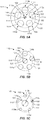
FIG. 5A-5C illustrate cross-sections of different regions of the coaxial electrical interconnect ofFIG. 1 , in accordance with the present disclosure. -
FIG. 6 is another coaxial electrical interconnect in accordance with the present disclosure. -
FIG. 7 is a support structure of the coaxial electrical interconnect ofFIG. 6 . -
FIG. 8 is a spring probe of the coaxial electrical interconnect ofFIG. 6 . -
FIG. 9 is yet another coaxial electrical interconnect in accordance with the present disclosure. - Conventional coaxial interconnects, using spring probes, have varying impedance mismatch dependent on the amount of compression of the spring probes. When large compression variability is required, very large impedance mismatch can occur. In some cases, impedance mismatch due to the electrical interconnect may require significant on-board matching. It is therefore highly desirable to have a coaxial electrical interconnect that can compress to vary in length while maintaining a constant characteristic impedance independent of the amount of compression of the electrical interconnect.
- Accordingly, a coaxial electrical interconnect is disclosed that can compress to vary in length and maintain a characteristic impedance regardless of the amount of compression. The coaxial electrical interconnect includes an inner conductor including an electrically conductive spring probe. The coaxial electrical interconnect also includes an outer conductor including a plurality of electrically conductive spring probes disposed about the inner conductor. Each spring probe has a barrel and a plunger biased out of the barrel. The plunger has a first plunger portion external to the barrel and a second plunger portion disposed at least partially in the barrel. The first and second plunger portions have different diameters. A barrel of the spring probe of the inner conductor is located proximate a plunger of at least one of the spring probes of the outer conductor.
- In addition, an electrically conductive spring probe for a coaxial electrical interconnect is disclosed. The electrically conductive spring probe includes a barrel and a plunger biased out of the barrel. The plunger has a first plunger portion external to the barrel and a second plunger portion disposed partially in the barrel. The first and second plunger portions have different diameters.
- A coaxial
electrical interconnect 100 is illustrated inFIG. 1 . The coaxialelectrical interconnect 100 is used as an RF interconnect to accommodate variations in distance between adjacent electrically coupled components (e.g., circuit boards) by being compressible in length. A characteristic impedance of the coaxialelectrical interconnect 100 can be maintained substantially constant as the length of interconnect varies, as described further below, which is highly desirable in impedance matched circuits. - The coaxial
electrical interconnect 100 comprises aninner conductor 101 and anouter conductor 102, which can be used for signal and ground connections, respectively. Theinner conductor 101 includes at least one electricallyconductive spring probe 110a and theouter conductor 102 includes aplurality of electricallyconductive spring probes 110b-f disposed about theinner conductor 101. As shown, thespring probes 110b-f of theouter conductor 102 can be disposed in a circular configuration about thespring probe 110a of theinner conductor 101. It should be recognized that theinner conductor 101 and theouter conductor 102 can each include any suitable number of spring probes. It should also be recognized that although thespring probes 110b-f of theouter conductor 102 are shown disposed in a circular configuration about thespring probe 110a of theinner conductor 101, thespring probes 110b-f of theouter conductor 102 can be disposed in any suitable configuration (e.g., shape) about thespring probe 110a of theinner conductor 101. - The coaxial
electrical interconnect 100 can also comprise a springprobe support member 120 configured to provide mechanical support for thespring probes 110a-f of the inner andouter conductors probe support member 120 is shown isolated inFIG. 2 and arepresentative spring probe 110 is shown isolated inFIG. 3 . - In general, as shown in
FIG. 3 , thespring probe 110 has abarrel 111 and aplunger 112 disposed at least partially in an opening or cavity of the barrel and biased out of thebarrel 111. Theplunger 112 has afirst plunger portion 113 external to thebarrel 111 and asecond plunger portion 114 disposed partially in thebarrel 111. The first andsecond plunger portions different diameters diameter 132 of thebarrel 111. Thefirst plunger portion 113 has alength 133 and thebarrel 111 has alength 134. in one aspect, discussed in more detail below, thelength 133 of thefirst plunger portion 113 and thelength 134 of thebarrel 111 can be substantially the same, which when combined with other similar spring probes in a coaxial electrical interconnect can facilitate, at least in part, maintaining a characteristic impedance of the electrical interconnect as the plungers move relative to the barrels to accommodate variations in distance between adjacent electrically coupled components. - The spring
probe support member 120 can include openings to receive portions of the spring probes. For example, as shown inFIG. 2 , the springprobe support member 120 can include an opening 121a to receive thefirst plunger portion 113a of thespring probe 110 andopenings 121b-f to receive thebarrels 111b-f of thespring probes 110b-f. The springprobe support member 120 is shown as having a cylindrical configuration but any suitable configuration may be utilized. - As shown in
FIG. 1 , thespring probe 110a of theinner conductor 101 is inverted relative to thespring probes 110b-f of theouter conductor 102. The barrel of thespring probe 110a of theinner conductor 101 is located proximate one or more plungers of thespring probes 110b-f of theouter conductor 102. Similarly, the plunger of thespring probe 110a of theinner conductor 101 can be located proximate one or more barrels of thespring probes 110b-f of theouter conductor 102. in addition, the springprobe support member 120 can be engaged with the first plunger portion of thespring probe 110a of theinner conductor 101 and with the barrels of thespring probes 110b-f of theouter conductor 102. In one aspect, thespring probes 110a-f of the inner andouter conductors - The
support member 120 can be constructed of any suitable material or combination of materials, which may include a dielectric material (e.g., a suitable polymer). In one aspect, thesupport member 120 can be constructed entirely of a dielectric material. In another aspect, illustrated inFIG. 2 , thesupport member 120 can be made of a dielectric material (indicated by reference number 122) around theopening 121a for the inner spring probe 110a. in addition, thesupport member 120 can have a conductive material (indicated by reference number 123) on the outside or periphery of thesupport member 120 that is at least partially in communication with theopenings 121b-f to electrically connect the outer spring probes 110b-f to the same electrical potential. - With continued reference to
FIGS. 1-3 ,FIGS. 4A and 4B illustrate schematic cross-sectional views of the coaxialelectrical interconnect 100 in an uncompressed configuration (FIG. 4A ) and a compressed configuration (FIG. 4B ), such when establishing an electrical connection between twoadjacent circuit boards inner conductor 101 is referred to by reference no. 110a and the spring probes of theouter conductor 102 are referred to collectively by reference nos. 110b-f. The spring probes 110a-f of the coaxialelectrical interconnect 100 can provide a certain range of motion or travel to accommodate variations in distance or stack-up of theadjacent circuit boards spring probe 110a-f includes a spring to bias the plunger out of the barrel and accommodate compression of the plunger into the barrel, as illustrated by aspring 115 of thespring probe 110a. The spring-loaded probes provide a reliable electrical contact between electrical components that may be located at a variable or unknown distance from one another. The configuration of the spring probes 110a-f can provide any suitable range of motion or travel to accommodate a given maximum variation in distance between electrical components. The ends of the spring probes 110a-f in contact with thecircuit boards - in one aspect, the length 130a of the
first plunger portion 113a of thespring probe 110a of theinner conductor 101 and thelengths 134b-f of thebarrels 111b-f of the spring probes 110b-f of theouter conductor 102 can be equal or substantially equal in length. Similarly, thelength 133b-f of thefirst plunger portions 113b-f of the spring probes 110b-f of theouter conductor 102 and thelength 134a thebarrel 111a of thespring probe 110a of theinner conductor 101 can be equal or substantially equal in length. As explained below, providing thefirst plunger portions 113a-f and thebarrels 111a-f with substantially equal lengths can facilitate maintaining a characteristic impedance of theelectrical interconnect 100 as the plungers 112a-f move relative to thebarrels 111a-f. - The coaxial
electrical interconnect 100 can also be divided into several regions, as afirst region 141, asecond region 142, and athird region 143, which can each have a nominal characteristic impedance. Such nominal characteristic impedances can be the same for all regions or they may vary from one another, as desired. Thefirst region 141 of theelectrical interconnect 100 can include thefirst plunger portion 113a of thespring probe 110a of theinner conductor 101 and thebarrels 111b-f of the spring probes 110b-f of theouter conductor 102. Thesecond region 142 of theelectrical interconnect 100 can include thesecond plunger portions 114a-f of the spring probes 110a-f of the inner andouter conductors barrels 111a-f. Thethird region 143 of theelectrical interconnect 100 can include thebarrel 111a of thespring probe 110a of theinner conductor 101 and thefirst plunger portions 113b-f of the spring probes 110b-f of theouter conductor 102. Note that the length of thesecond region 142 changes as the coaxialelectrical interconnect 100 is compressed (e.g., fromlength 135 inFIG. 4A to a shorter length 135' inFIG. 4B ). Because thesecond plunger portions 114a-f are partially disposed in thebarrels 111a-f and move in and out of the barrels depending on the amount of compression of the coaxialelectrical interconnect 100, thesecond region 142 is the only one of the three regions inFIGS. 4A and 4B that undergoes a change in length as theinterconnect 100 is compressed. Thus, the lengths of the first andthird regions interconnect 100, while thesecond region 142 adjusts in length for the amount of compression. - Viewed in cross-section in
FIGS. 5A-5C , thefirst region 141, thesecond region 142, and thethird region 143, respectively, can each be configured to provide a given characteristic impedance. Generally, characteristic impedance is determined by the geometry and materials of the electrical interconnect. In this case, characteristic impedance of each region 141-143 can be calculated using the diameters of theinner conductor 101 and theouter conductor 102, as well as accounting for a support structure (e.g., the spring probe support member 120) of the electrical interconnect where applicable. In one aspect, the material of the springprobe support member 120 can be used to tune the characteristic impedance of the region in which it resides (i.e., thefirst region 141 in this example). A support structure can interface with components of the first, second, and/or third regions as desired. Thespring probe 110a of theinner conductor 101 is shown located at the center of a circular arrangement of the spring probes 110b-f. The centers or longitudinal axes of the spring probes 110b-f lie on acircle 150, which remains the same diameter and at the same location relative to thespring probe 110a for each region 141-143 because the spring probes 110b-f are parallel to one another, although other configurations are possible. Acircle FIGS. 5A-5C , respectively, bounds the spring probes 110b-f and defines a diameter of theouter conductor 102 for each region 141-143. - Due to the relationship of the
diameter 130 for thefirst plunger portions 113a-f, thediameter 131 for thesecond plunger portions 114a-f and, thediameter 132 for thebarrels 111a-f the diameters of thecircles first region 141 to thethird region 143 while the diameters of theinner conductor 101 increase from thefirst region 141 to thethird region 143. This inverse relationship in effective diameters of the inner andouter conductors first region 141 to thethird region 143 can be utilized to configure the characteristic impedances for each region such that the characteristic impedances are equal across the regions. Thus, for thefirst region 141, where there is crowding in theouter conductor 102 due to the relatively large diameter of thebarrels 111b-f, the diameter of theinner conductor 101 is at its smallest (e.g., the diameter of thefirst plunger portion 110a). This configuration of thefirst region 141, when accounting for the presence of thesupport member 120 material, which may be a dielectric material (e.g., a suitable polymer), can provide a characteristic impedance that is equal to the characteristic impedance of thesecond region 142 where the crowding in the outer conductor is reduced as the diameter of the inner conductor increases, and equal to the characteristic impedance of thethird region 143 where the crowding in the outer conductor is reduced even further as thediameter 132 of theinner conductor 101 increases even more. Thus, the coaxial electrical interconnect inner andouter diameters outer conductors electrical interconnect 100 as a whole. It should be recognized that identical spring probes can be utilized throughout theinterconnect 100 orinterconnect 100 can incorporate different spring probes, which may have different diameters for the barrels, and plunger portions. - As mentioned with regard to
FIGS. 4A and 4B , because the lengths of the first andthird regions interconnect 100, these regions will maintain the same characteristic impedance during compression of theinterconnect 100. Furthermore, because thesecond region 142 merely changes in length (e.g., fromlength 135 to length 135') while the cross-section illustrated inFIG. 5B remains the same, the characteristic impedance of the second region will also be maintained during compression of theinterconnect 100. Thus, thesecond region 142 can adjust in length for the amount of compression of theinterconnect 100 without altering the characteristic impedance of thesecond region 142. In other words, the characteristic impedance of theinterconnect 100 can be maintained substantially constant or stable throughout the range of travel of the spring probes 110a-f. As a result, compression of theinterconnect 100 can have a minimal effect on impedance mismatch over a wide frequency band. Theinterconnect 100 can therefore provide for a high variability of compression without degrading voltage standing wave ratio (VSWR) independent of the compression of theinterconnect 100. - The
first plunger portion 110a and/or any of thebarrels 111b-f of the spring probes 110a-f can be movable or fixed relative to thesupport member 120. For example, thefirst plunger portion 110a and/or any of thebarrels 111b-f can be threadedly coupled, adhesively coupled, or configured to have an interference fit with thesupport member 120 to secure thefirst plunger portion 110a and/or any of thebarrels 111b-f to thesupport member 120. - The tips of the spring probes and the protrusion from the support member near the
circuit board 103 are examples of instances where the characteristic impedance is not consistent with the nominal characteristic impedance for a given region, as determined based on the cross-sections ofFIGS. 5A-5C . Similarly, although thelengths first plunger portion 113a and thebarrels 111b-f in thefirst region 141 are substantially equal, and thelengths barrel 111a and thefirst plunger portions 113b-f in thefirst region 141 are substantially equal, slight variations in these lengths due to manufacturing tolerances may result in local instances where the characteristic impedance is not consistent with the nominal characteristic impedance for a given region. These variances from the nominal characteristic impedance can be adjusted or controlled based on the application. For example, a high frequency application may be less tolerant than a lower frequency application and therefore may necessitate tighter control on such local variations from the nominal characteristic impedance than for a lower frequency application. Thus, terms such as "substantially," "maintain," and "constant" when used in the context of component dimensions or characteristic impedance will be understood by one skilled in the art in light of the particular application of the coaxial electrical interconnect. -
FIG. 6 illustrates a schematic cross-sectional view of a coaxialelectrical interconnect 200. The coaxialelectrical interconnect 200 is similar to the coaxialelectrical interconnect 100 discussed above in many respects. Several features are illustrated that can facilitate capture or retention of spring probes and/or spring probe components as well as provide mechanical support for the spring probes. In this case, aninner conductor 201 has aspring probe 211a and anouter conductor 202 can include six spring probes referred to collectively by reference nos. 210b-g.First plunger portion 213a of thespring probe 210a can be received in anopening 221a of a springprobe support member 220, and barrels 211b-g of the spring probes 210b-g can be received inopenings 221b-g of the springprobe support member 220. Thefirst plunger portion 213a and thebarrels 211b-g and can be configured to move or slide relative to the springprobe support member 220 in theopenings 221a-g, respectively. An additional springprobe support member 222 can be coupled to the springprobe support member 220 to capture or retain the spring probes 210a-g as well as to provide mechanical support for the spring probes. The springprobe support members FIG. 7 and arepresentative spring probe 210 is shown isolated inFIG. 8 . - The
spring probe 210 can include adetent 216 in abarrel 211 to interface with acapture feature 217 of asecond plunger portion 214 of aplunger 212 to maintain theplunger 212 at least partially within thebarrel 211. Thesecond plunger portion 214 and thedetent 216 can be configured to provide a suitable range of motion for theplunger 212 relative to thebarrel 211. Thespring probe 210 can also include acapture feature 218, such as a flange on thebarrel 211, to capture or retain the spring probe with the springprobe support members probe support member 220 can include one ormore recesses 223, such as a counter bore. Therecess 223 can be configured to accommodate the capture features 218b-g on thebarrels 211b-g of theouter conductor 202 spring probes 210b-g, as shown inFIG. 6 . The springprobe support member 222 can have aninner diameter 224 configured to provide a mechanical interference with the capture features 218b-g of thebarrels 211b-g in therecess 223, which can limit a range of motion for the barrels relative to thesupport member 220 and capture or retain the spring probes 210b-g of theouter conductor 202 with the springprobe support members probe support member 222 can also have anend 225 withalignment openings 226a-g configured to receive thefirst plunger portions 213b-g of the spring probes 210b-g of theouter conductor 202 and thebarrel 211a of thespring probe 210a of theinner conductor 201. Theopenings 226a-g can be sized to allow movement of thefirst plunger portions 213b-g and thebarrel 211a relative to the springprobe support member 222 during compression of theinterconnect 200, while providing adequate mechanical support for lateral deflection of the spring probes 210a-g. Theopening 226a for thebarrel 211a can also be configured to provide a mechanical interference with the capture feature 218a of thebarrel 211a to capture or retain thespring probe 210a of theinner conductor 201 with the springprobe support members probe support member 220 and/or the springprobe support member 222 can comprise an overloading type of dielectric material (e.g., metalized plastic) to create a ground shield around the spring probes 210a-g. - The presence of the spring probe capture features 218a-g may introduce a slight impedance mismatch. For example, the flanges on the
barrels 211a-g as well as the springprobe support member 222 can introduce material that can cause local variations in the nominal impedance of a given region. As mentioned above, these local variations in impedance can be reduced or minimized depending on the application to acceptable levels. For example, theinterconnect 200 can be fine-tuned for higher frequency applications by includinglocal diameter expansions 219a and/orcontractions 219b in adjacent components to offset the presence or absence of material in a neighboring component (e.g.,detent 216a and capture feature 218a). In one aspect, a material, such as a dielectric material, can be included strategically to address local impedance variations. As shown inFIGS. 6 and7 , the springprobe support member 222 can be hollowed out with a minimal amount of material at theend 225 to provide mechanical support for the spring probes 210a-g. In one aspect, the springprobe support member 222 can be configured with holes, suitable material type, etc. to approximate the resistance of air so that impedance is maintained within acceptable levels locally. -
FIG. 9 illustrates a schematic cross-sectional view of a coaxialelectrical interconnect 300. The coaxialelectrical interconnect 300 includes many similarities to the coaxialelectrical interconnects electrical interconnect 300 is configured withspring probes 310a-g that are double-ended, whereas the spring probes of theelectrical interconnects interconnect 300. In this case, thespring probe 310a of an inner conductor 301 comprises twobarrels plunger 312a, and the spring probes 310b-g of an outer conductor 302 comprise twoplungers 312b-g, 312b'-g' oriented on opposite ends of abarrel 311b-g. The spring probes 310a-g utilized in this example therefore are not all alike or identical. The result of such a configuration is five different regions 341-345, each of which can be configured to have a given nominal characteristic impedance, as described herein. It should be recognized that any suitable number of different regions can be utilized. - In accordance with the present invention, a method according to claim 14, for facilitating a matched impedance electrical connection is disclosed. In one aspect of the method, facilitating a constant characteristic impedance comprises sizing the first plunger portion of the spring probe of the inner conductor and the barrels of the spring probes of the outer conductor with substantially equal lengths. It is noted that no specific order is required in this method, though generally in one embodiment, these method steps can be carried out sequentially.
Claims (15)
- A coaxial electrical interconnect (100, 200, 300), comprising:an inner conductor (101, 201, 301) including an electrically conductive spring probe (110a, 210a, 310a); andan outer conductor (102, 202) including a plurality of electrically conductive spring probes (110b-g, 210b-g, 310b-g) disposed about the inner conductor,each spring probe having a barrel (111, 211, 311), a plunger (112, 212,312) and a spring (115) arranged to bias the plunger out of the barrel, the plunger having a first plunger portion (113, 213) external to the barrel and a second plunger portion (114, 214) disposed partially in the barrel, the first and second plunger portions having different diameters,wherein the barrel of the spring probe of the inner conductor is located proximate to a plunger of at least one of the spring probes of the outer conductor; and
wherein the spring probe of the inner conductor is inverted relative to the spring probes of the outer conductor. - The coaxial electrical interconnect of claim 1, wherein the spring probes of the inner and outer conductors are substantially identical.
- The coaxial electrical interconnect of claim 1, wherein the spring probes of the outer conductor are disposed in a circular configuration about the spring probe of the inner conductor.
- The coaxial electrical interconnect of claim 1, further comprising a spring probe support member (120, 220) configured to provide mechanical support for the spring probes of the inner and outer conductors.
- The coaxial electrical interconnect of claim 4, wherein the spring probe support member is constructed of a dielectric material.
- The coaxial electrical interconnect of claim 6, wherein the spring probe support member is engaged with the first plunger portion of the spring probe of the inner conductor and with the barrels of the spring probes of the outer conductor.
- The coaxial electrical interconnect of claim 6, further comprising a second spring probe support member (222) coupled to the first spring probe support member, the second spring probe support member configured to provide mechanical support for the barrel of the spring probe of the inner conductor and the first plunger portions of the spring probes of the outer conductor.
- The coaxial electrical interconnect of claim 7, wherein the barrels of the spring probes comprise capture features (216), and wherein the first and second spring probe support members are configured to provide mechanical interference with the capture features to maintain the spring probes with the first and second support members.
- The coaxial electrical interconnect of claim 1, wherein the spring probe of the inner conductor comprises two barrels (311a, 311a') oriented on opposite ends of the plunger.
- The coaxial electrical interconnect of claim 1, wherein the spring probes of the outer conductor comprise two plungers (310b-g, 310b'-g') oriented on opposite ends of the barrel.
- The coaxial electrical interconnect of claim 1, wherein the first plunger portion of the spring probe of the inner conductor and the barrels of the spring probes of the outer conductor are substantially equal in length to facilitate maintaining a characteristic impedance of the electrical interconnect as the plungers move relative to the barrels; or
wherein the spring probe of the inner conductor and the plurality of spring probes of the outer conductor are sized and positioned relative to one another to provide a given characteristic impedance. - The coaxial electrical interconnect of claim 1, wherein a first region (141) of the electrical interconnect comprises the first plunger portion of the spring probe of the inner conductor and the barrels of the spring probes of the outer conductor, a second region (142) of the electrical interconnect comprises the second plunger portions of the spring probes of the inner and outer conductors, and a third region (143) of the electrical interconnect comprises the barrel of the spring probe of the inner conductor and the first plunger portions of the spring probes of the outer conductor, and wherein the spring probes of the inner and outer conductors are sized and positioned relative to one another to provide given characteristic impedances for the first, second, and third regions.
- The coaxial electrical interconnect of claim 12, wherein the given characteristic impedances of the first, second, and third regions are the same; or
wherein the first region further comprises a dielectric support member configured to provide mechanical support for the spring probes of the inner and outer conductors. - A method for facilitating a matched impedance electrical connection, comprising the following steps comprising:providing a coaxial electrical interconnect (100, 200, 300) according to claim 1; andfacilitating a constant characteristic impedance of the electrical interconnect as the plungers move relative to the barrels.
- The method of claim 14, wherein the step of facilitating a constant characteristic impedance comprises sizing the first plunger portion of the spring probe of the inner conductor and the barrels of the spring probes of the outer conductor with substantially equal lengths.
Applications Claiming Priority (2)
| Application Number | Priority Date | Filing Date | Title |
|---|---|---|---|
| US14/872,001 US9590359B1 (en) | 2015-09-30 | 2015-09-30 | Coaxial electrical interconnect |
| PCT/US2016/040513 WO2017058325A1 (en) | 2015-09-30 | 2016-06-30 | Coaxial electrical interconnect |
Publications (2)
| Publication Number | Publication Date |
|---|---|
| EP3357128A1 EP3357128A1 (en) | 2018-08-08 |
| EP3357128B1 true EP3357128B1 (en) | 2019-02-20 |
Family
ID=56411941
Family Applications (1)
| Application Number | Title | Priority Date | Filing Date |
|---|---|---|---|
| EP16738974.1A Active EP3357128B1 (en) | 2015-09-30 | 2016-06-30 | Coaxial electrical interconnect |
Country Status (4)
| Country | Link |
|---|---|
| US (3) | US9590359B1 (en) |
| EP (1) | EP3357128B1 (en) |
| TW (1) | TWI626798B (en) |
| WO (1) | WO2017058325A1 (en) |
Families Citing this family (7)
| Publication number | Priority date | Publication date | Assignee | Title |
|---|---|---|---|---|
| CA3003977A1 (en) * | 2017-05-05 | 2018-11-05 | Huys Industries Limited | Welding ground apparatus |
| JP6882941B2 (en) * | 2017-06-16 | 2021-06-02 | ヒロセ電機株式会社 | Coaxial connector assembly |
| USD900036S1 (en) * | 2017-08-24 | 2020-10-27 | Asm Ip Holding B.V. | Heater electrical connector and adapter |
| FR3082061B1 (en) * | 2018-06-01 | 2021-05-21 | Thales Sa | CONNECTION DEVICE AND ASSEMBLY INCLUDING SUCH A CONNECTION DEVICE AND AN ELECTRONIC DEVICE |
| US10516224B1 (en) * | 2018-12-21 | 2019-12-24 | Raytheon Company | Edge launch connector for electronics assemblies |
| CN114527307B (en) * | 2022-02-11 | 2024-03-22 | 木王芯(苏州)半导体科技有限公司 | Three-head test probe with broken spring protection characteristic |
| CN114744426A (en) * | 2022-03-14 | 2022-07-12 | 上海航天科工电器研究院有限公司 | A VITA67 RF Module Based on Gross Button Connection |
Citations (1)
| Publication number | Priority date | Publication date | Assignee | Title |
|---|---|---|---|---|
| EP2624369A1 (en) * | 2012-02-01 | 2013-08-07 | Tyco Electronics Corporation | Electrical connector with retractable hood |
Family Cites Families (19)
| Publication number | Priority date | Publication date | Assignee | Title |
|---|---|---|---|---|
| DE1665188A1 (en) | 1968-01-31 | 1971-02-11 | Mini Verkehrswesen | Cable coupling, especially in automatic rail vehicle couplings |
| US4983909A (en) * | 1989-11-28 | 1991-01-08 | Everett/Charles Contact Products, Inc. | Repetitive-switching |
| US5009613A (en) * | 1990-05-01 | 1991-04-23 | Interconnect Devices, Inc. | Spring contact twister probe for testing electrical printed circuit boards |
| US5159265A (en) * | 1991-09-19 | 1992-10-27 | Motorola, Inc. | Pivotable spring contact |
| US5233290A (en) * | 1991-11-05 | 1993-08-03 | Everett Charles Technologies, Inc. | Switch probe |
| US5618205A (en) | 1993-04-01 | 1997-04-08 | Trw Inc. | Wideband solderless right-angle RF interconnect |
| JPH0682582U (en) * | 1993-05-07 | 1994-11-25 | 矢崎総業株式会社 | Connector terminal tester |
| US6366185B1 (en) | 2000-01-12 | 2002-04-02 | Raytheon Company | Vertical interconnect between coaxial or GCPW circuits and airline via compressible center conductors |
| US7063542B2 (en) * | 2002-06-13 | 2006-06-20 | Paricon Technologies Corporation | Compliant electrical probe device incorporating anisotropically conductive elastomer and flexible circuits |
| US6878016B2 (en) * | 2002-12-12 | 2005-04-12 | Symbol Technologies, Inc. | High cycle connector contact system |
| US6958670B2 (en) | 2003-08-01 | 2005-10-25 | Raytheon Company | Offset connector with compressible conductor |
| CN2682639Y (en) * | 2003-11-20 | 2005-03-02 | 上海莫仕连接器有限公司 | Crimp connected conductive terminal |
| US7841865B2 (en) * | 2008-09-19 | 2010-11-30 | Ivus Industries, Llc | Orientationless spring probe receptacle assembly |
| JP5133196B2 (en) * | 2008-10-10 | 2013-01-30 | モレックス インコーポレイテド | Probe connector |
| JP5960383B2 (en) * | 2010-06-01 | 2016-08-02 | スリーエム イノベイティブ プロパティズ カンパニー | Contact holder |
| WO2012067076A1 (en) * | 2010-11-15 | 2012-05-24 | 日本発條株式会社 | Connection terminal |
| US8506307B2 (en) * | 2010-12-02 | 2013-08-13 | Interconnect Devices, Inc. | Electrical connector with embedded shell layer |
| EP2533374A1 (en) | 2011-06-06 | 2012-12-12 | novero GmbH | Connector assembly with a magnetic fixation |
| US8758066B2 (en) * | 2012-02-03 | 2014-06-24 | Interconnect Devices, Inc. | Electrical connector with insulation member |
-
2015
- 2015-09-30 US US14/872,001 patent/US9590359B1/en active Active
-
2016
- 2016-06-30 WO PCT/US2016/040513 patent/WO2017058325A1/en not_active Ceased
- 2016-06-30 EP EP16738974.1A patent/EP3357128B1/en active Active
- 2016-07-15 TW TW105122450A patent/TWI626798B/en active
-
2017
- 2017-02-28 US US15/445,841 patent/US20170170617A1/en not_active Abandoned
-
2018
- 2018-10-17 US US16/163,418 patent/US10693266B2/en active Active
Patent Citations (1)
| Publication number | Priority date | Publication date | Assignee | Title |
|---|---|---|---|---|
| EP2624369A1 (en) * | 2012-02-01 | 2013-08-07 | Tyco Electronics Corporation | Electrical connector with retractable hood |
Also Published As
| Publication number | Publication date |
|---|---|
| EP3357128A1 (en) | 2018-08-08 |
| TWI626798B (en) | 2018-06-11 |
| TW201712963A (en) | 2017-04-01 |
| WO2017058325A1 (en) | 2017-04-06 |
| US20170093092A1 (en) | 2017-03-30 |
| US10693266B2 (en) | 2020-06-23 |
| US20190123498A1 (en) | 2019-04-25 |
| US9590359B1 (en) | 2017-03-07 |
| US20170170617A1 (en) | 2017-06-15 |
Similar Documents
| Publication | Publication Date | Title |
|---|---|---|
| EP3547459B1 (en) | Board mating connector in which signal contact unit and ground contact unit are interlocked | |
| US10693266B2 (en) | Coaxial electrical interconnect | |
| US9653831B2 (en) | Float adapter for electrical connector | |
| US9735531B2 (en) | Float adapter for electrical connector and method for making the same | |
| EP2615699B1 (en) | RF Connector | |
| EP3487007B1 (en) | High frequency electrical connector | |
| US10164384B2 (en) | Coaxial connector | |
| US6754060B2 (en) | Protective device | |
| US9531140B2 (en) | Coaxial protective device | |
| EP3547458B1 (en) | Board mating connector including ground unit in which tapered portion is formed | |
| US11450996B2 (en) | Connector assembly for connecting a cable to an electrical component | |
| WO2021032333A1 (en) | Coaxial rf connector | |
| EP3780292B1 (en) | Low passive intermodulation connector system | |
| EP3043425B1 (en) | Float adapter for electrical connector | |
| US9502825B2 (en) | Shunt for electrical connector | |
| KR102874426B1 (en) | Broadband array antenna, antenna assembly, and antenna apparatus with uniform power supply structure | |
| HK1244357A1 (en) | Float adapter for electrical connector and method for making the same |
Legal Events
| Date | Code | Title | Description |
|---|---|---|---|
| STAA | Information on the status of an ep patent application or granted ep patent |
Free format text: STATUS: THE INTERNATIONAL PUBLICATION HAS BEEN MADE |
|
| PUAI | Public reference made under article 153(3) epc to a published international application that has entered the european phase |
Free format text: ORIGINAL CODE: 0009012 |
|
| STAA | Information on the status of an ep patent application or granted ep patent |
Free format text: STATUS: REQUEST FOR EXAMINATION WAS MADE |
|
| 17P | Request for examination filed |
Effective date: 20180419 |
|
| AK | Designated contracting states |
Kind code of ref document: A1 Designated state(s): AL AT BE BG CH CY CZ DE DK EE ES FI FR GB GR HR HU IE IS IT LI LT LU LV MC MK MT NL NO PL PT RO RS SE SI SK SM TR |
|
| AX | Request for extension of the european patent |
Extension state: BA ME |
|
| GRAP | Despatch of communication of intention to grant a patent |
Free format text: ORIGINAL CODE: EPIDOSNIGR1 |
|
| STAA | Information on the status of an ep patent application or granted ep patent |
Free format text: STATUS: GRANT OF PATENT IS INTENDED |
|
| RIC1 | Information provided on ipc code assigned before grant |
Ipc: H01R 24/44 20110101ALI20181026BHEP Ipc: H01R 13/6473 20110101ALI20181026BHEP Ipc: H01R 24/86 20110101ALI20181026BHEP Ipc: H01R 13/405 20060101ALN20181026BHEP Ipc: H01R 12/71 20110101AFI20181026BHEP Ipc: H01R 12/91 20110101ALI20181026BHEP Ipc: G01R 1/073 20060101ALI20181026BHEP Ipc: H01R 13/24 20060101ALN20181026BHEP Ipc: H01R 12/75 20110101ALI20181026BHEP Ipc: H01R 31/06 20060101ALI20181026BHEP |
|
| DAX | Request for extension of the european patent (deleted) | ||
| INTG | Intention to grant announced |
Effective date: 20181122 |
|
| DAV | Request for validation of the european patent (deleted) | ||
| GRAS | Grant fee paid |
Free format text: ORIGINAL CODE: EPIDOSNIGR3 |
|
| GRAA | (expected) grant |
Free format text: ORIGINAL CODE: 0009210 |
|
| STAA | Information on the status of an ep patent application or granted ep patent |
Free format text: STATUS: THE PATENT HAS BEEN GRANTED |
|
| AK | Designated contracting states |
Kind code of ref document: B1 Designated state(s): AL AT BE BG CH CY CZ DE DK EE ES FI FR GB GR HR HU IE IS IT LI LT LU LV MC MK MT NL NO PL PT RO RS SE SI SK SM TR |
|
| REG | Reference to a national code |
Ref country code: GB Ref legal event code: FG4D |
|
| REG | Reference to a national code |
Ref country code: CH Ref legal event code: EP |
|
| REG | Reference to a national code |
Ref country code: DE Ref legal event code: R096 Ref document number: 602016010172 Country of ref document: DE |
|
| REG | Reference to a national code |
Ref country code: AT Ref legal event code: REF Ref document number: 1099417 Country of ref document: AT Kind code of ref document: T Effective date: 20190315 |
|
| REG | Reference to a national code |
Ref country code: IE Ref legal event code: FG4D |
|
| REG | Reference to a national code |
Ref country code: LT Ref legal event code: MG4D Ref country code: NL Ref legal event code: MP Effective date: 20190220 |
|
| PG25 | Lapsed in a contracting state [announced via postgrant information from national office to epo] |
Ref country code: LT Free format text: LAPSE BECAUSE OF FAILURE TO SUBMIT A TRANSLATION OF THE DESCRIPTION OR TO PAY THE FEE WITHIN THE PRESCRIBED TIME-LIMIT Effective date: 20190220 Ref country code: SE Free format text: LAPSE BECAUSE OF FAILURE TO SUBMIT A TRANSLATION OF THE DESCRIPTION OR TO PAY THE FEE WITHIN THE PRESCRIBED TIME-LIMIT Effective date: 20190220 Ref country code: PT Free format text: LAPSE BECAUSE OF FAILURE TO SUBMIT A TRANSLATION OF THE DESCRIPTION OR TO PAY THE FEE WITHIN THE PRESCRIBED TIME-LIMIT Effective date: 20190620 Ref country code: NO Free format text: LAPSE BECAUSE OF FAILURE TO SUBMIT A TRANSLATION OF THE DESCRIPTION OR TO PAY THE FEE WITHIN THE PRESCRIBED TIME-LIMIT Effective date: 20190520 Ref country code: FI Free format text: LAPSE BECAUSE OF FAILURE TO SUBMIT A TRANSLATION OF THE DESCRIPTION OR TO PAY THE FEE WITHIN THE PRESCRIBED TIME-LIMIT Effective date: 20190220 |
|
| PG25 | Lapsed in a contracting state [announced via postgrant information from national office to epo] |
Ref country code: LV Free format text: LAPSE BECAUSE OF FAILURE TO SUBMIT A TRANSLATION OF THE DESCRIPTION OR TO PAY THE FEE WITHIN THE PRESCRIBED TIME-LIMIT Effective date: 20190220 Ref country code: BG Free format text: LAPSE BECAUSE OF FAILURE TO SUBMIT A TRANSLATION OF THE DESCRIPTION OR TO PAY THE FEE WITHIN THE PRESCRIBED TIME-LIMIT Effective date: 20190520 Ref country code: IS Free format text: LAPSE BECAUSE OF FAILURE TO SUBMIT A TRANSLATION OF THE DESCRIPTION OR TO PAY THE FEE WITHIN THE PRESCRIBED TIME-LIMIT Effective date: 20190620 Ref country code: RS Free format text: LAPSE BECAUSE OF FAILURE TO SUBMIT A TRANSLATION OF THE DESCRIPTION OR TO PAY THE FEE WITHIN THE PRESCRIBED TIME-LIMIT Effective date: 20190220 Ref country code: HR Free format text: LAPSE BECAUSE OF FAILURE TO SUBMIT A TRANSLATION OF THE DESCRIPTION OR TO PAY THE FEE WITHIN THE PRESCRIBED TIME-LIMIT Effective date: 20190220 Ref country code: GR Free format text: LAPSE BECAUSE OF FAILURE TO SUBMIT A TRANSLATION OF THE DESCRIPTION OR TO PAY THE FEE WITHIN THE PRESCRIBED TIME-LIMIT Effective date: 20190521 Ref country code: NL Free format text: LAPSE BECAUSE OF FAILURE TO SUBMIT A TRANSLATION OF THE DESCRIPTION OR TO PAY THE FEE WITHIN THE PRESCRIBED TIME-LIMIT Effective date: 20190220 |
|
| REG | Reference to a national code |
Ref country code: AT Ref legal event code: MK05 Ref document number: 1099417 Country of ref document: AT Kind code of ref document: T Effective date: 20190220 |
|
| PG25 | Lapsed in a contracting state [announced via postgrant information from national office to epo] |
Ref country code: ES Free format text: LAPSE BECAUSE OF FAILURE TO SUBMIT A TRANSLATION OF THE DESCRIPTION OR TO PAY THE FEE WITHIN THE PRESCRIBED TIME-LIMIT Effective date: 20190220 Ref country code: AL Free format text: LAPSE BECAUSE OF FAILURE TO SUBMIT A TRANSLATION OF THE DESCRIPTION OR TO PAY THE FEE WITHIN THE PRESCRIBED TIME-LIMIT Effective date: 20190220 Ref country code: SK Free format text: LAPSE BECAUSE OF FAILURE TO SUBMIT A TRANSLATION OF THE DESCRIPTION OR TO PAY THE FEE WITHIN THE PRESCRIBED TIME-LIMIT Effective date: 20190220 Ref country code: RO Free format text: LAPSE BECAUSE OF FAILURE TO SUBMIT A TRANSLATION OF THE DESCRIPTION OR TO PAY THE FEE WITHIN THE PRESCRIBED TIME-LIMIT Effective date: 20190220 Ref country code: CZ Free format text: LAPSE BECAUSE OF FAILURE TO SUBMIT A TRANSLATION OF THE DESCRIPTION OR TO PAY THE FEE WITHIN THE PRESCRIBED TIME-LIMIT Effective date: 20190220 Ref country code: DK Free format text: LAPSE BECAUSE OF FAILURE TO SUBMIT A TRANSLATION OF THE DESCRIPTION OR TO PAY THE FEE WITHIN THE PRESCRIBED TIME-LIMIT Effective date: 20190220 Ref country code: IT Free format text: LAPSE BECAUSE OF FAILURE TO SUBMIT A TRANSLATION OF THE DESCRIPTION OR TO PAY THE FEE WITHIN THE PRESCRIBED TIME-LIMIT Effective date: 20190220 Ref country code: EE Free format text: LAPSE BECAUSE OF FAILURE TO SUBMIT A TRANSLATION OF THE DESCRIPTION OR TO PAY THE FEE WITHIN THE PRESCRIBED TIME-LIMIT Effective date: 20190220 |
|
| REG | Reference to a national code |
Ref country code: DE Ref legal event code: R097 Ref document number: 602016010172 Country of ref document: DE |
|
| PG25 | Lapsed in a contracting state [announced via postgrant information from national office to epo] |
Ref country code: PL Free format text: LAPSE BECAUSE OF FAILURE TO SUBMIT A TRANSLATION OF THE DESCRIPTION OR TO PAY THE FEE WITHIN THE PRESCRIBED TIME-LIMIT Effective date: 20190220 Ref country code: SM Free format text: LAPSE BECAUSE OF FAILURE TO SUBMIT A TRANSLATION OF THE DESCRIPTION OR TO PAY THE FEE WITHIN THE PRESCRIBED TIME-LIMIT Effective date: 20190220 |
|
| PLBE | No opposition filed within time limit |
Free format text: ORIGINAL CODE: 0009261 |
|
| STAA | Information on the status of an ep patent application or granted ep patent |
Free format text: STATUS: NO OPPOSITION FILED WITHIN TIME LIMIT |
|
| PG25 | Lapsed in a contracting state [announced via postgrant information from national office to epo] |
Ref country code: AT Free format text: LAPSE BECAUSE OF FAILURE TO SUBMIT A TRANSLATION OF THE DESCRIPTION OR TO PAY THE FEE WITHIN THE PRESCRIBED TIME-LIMIT Effective date: 20190220 |
|
| 26N | No opposition filed |
Effective date: 20191121 |
|
| PG25 | Lapsed in a contracting state [announced via postgrant information from national office to epo] |
Ref country code: MC Free format text: LAPSE BECAUSE OF FAILURE TO SUBMIT A TRANSLATION OF THE DESCRIPTION OR TO PAY THE FEE WITHIN THE PRESCRIBED TIME-LIMIT Effective date: 20190220 |
|
| REG | Reference to a national code |
Ref country code: CH Ref legal event code: PL |
|
| REG | Reference to a national code |
Ref country code: BE Ref legal event code: MM Effective date: 20190630 |
|
| PG25 | Lapsed in a contracting state [announced via postgrant information from national office to epo] |
Ref country code: TR Free format text: LAPSE BECAUSE OF FAILURE TO SUBMIT A TRANSLATION OF THE DESCRIPTION OR TO PAY THE FEE WITHIN THE PRESCRIBED TIME-LIMIT Effective date: 20190220 |
|
| PG25 | Lapsed in a contracting state [announced via postgrant information from national office to epo] |
Ref country code: IE Free format text: LAPSE BECAUSE OF NON-PAYMENT OF DUE FEES Effective date: 20190630 |
|
| PG25 | Lapsed in a contracting state [announced via postgrant information from national office to epo] |
Ref country code: LU Free format text: LAPSE BECAUSE OF NON-PAYMENT OF DUE FEES Effective date: 20190630 Ref country code: BE Free format text: LAPSE BECAUSE OF NON-PAYMENT OF DUE FEES Effective date: 20190630 Ref country code: LI Free format text: LAPSE BECAUSE OF NON-PAYMENT OF DUE FEES Effective date: 20190630 Ref country code: CH Free format text: LAPSE BECAUSE OF NON-PAYMENT OF DUE FEES Effective date: 20190630 |
|
| PG25 | Lapsed in a contracting state [announced via postgrant information from national office to epo] |
Ref country code: CY Free format text: LAPSE BECAUSE OF FAILURE TO SUBMIT A TRANSLATION OF THE DESCRIPTION OR TO PAY THE FEE WITHIN THE PRESCRIBED TIME-LIMIT Effective date: 20190220 |
|
| PG25 | Lapsed in a contracting state [announced via postgrant information from national office to epo] |
Ref country code: MT Free format text: LAPSE BECAUSE OF FAILURE TO SUBMIT A TRANSLATION OF THE DESCRIPTION OR TO PAY THE FEE WITHIN THE PRESCRIBED TIME-LIMIT Effective date: 20190220 Ref country code: HU Free format text: LAPSE BECAUSE OF FAILURE TO SUBMIT A TRANSLATION OF THE DESCRIPTION OR TO PAY THE FEE WITHIN THE PRESCRIBED TIME-LIMIT; INVALID AB INITIO Effective date: 20160630 |
|
| PG25 | Lapsed in a contracting state [announced via postgrant information from national office to epo] |
Ref country code: SI Free format text: LAPSE BECAUSE OF FAILURE TO SUBMIT A TRANSLATION OF THE DESCRIPTION OR TO PAY THE FEE WITHIN THE PRESCRIBED TIME-LIMIT Effective date: 20190220 |
|
| PG25 | Lapsed in a contracting state [announced via postgrant information from national office to epo] |
Ref country code: MK Free format text: LAPSE BECAUSE OF FAILURE TO SUBMIT A TRANSLATION OF THE DESCRIPTION OR TO PAY THE FEE WITHIN THE PRESCRIBED TIME-LIMIT Effective date: 20190220 |
|
| P01 | Opt-out of the competence of the unified patent court (upc) registered |
Effective date: 20230530 |
|
| PGFP | Annual fee paid to national office [announced via postgrant information from national office to epo] |
Ref country code: DE Payment date: 20250520 Year of fee payment: 10 |
|
| PGFP | Annual fee paid to national office [announced via postgrant information from national office to epo] |
Ref country code: GB Payment date: 20250520 Year of fee payment: 10 |
|
| PGFP | Annual fee paid to national office [announced via postgrant information from national office to epo] |
Ref country code: FR Payment date: 20250520 Year of fee payment: 10 |