EP3356682B1 - Low-cavitation impeller and pump - Google Patents
Low-cavitation impeller and pump Download PDFInfo
- Publication number
- EP3356682B1 EP3356682B1 EP16852599.6A EP16852599A EP3356682B1 EP 3356682 B1 EP3356682 B1 EP 3356682B1 EP 16852599 A EP16852599 A EP 16852599A EP 3356682 B1 EP3356682 B1 EP 3356682B1
- Authority
- EP
- European Patent Office
- Prior art keywords
- blade
- impeller
- centrifugal pump
- main
- main blade
- Prior art date
- Legal status (The legal status is an assumption and is not a legal conclusion. Google has not performed a legal analysis and makes no representation as to the accuracy of the status listed.)
- Active
Links
Images


Classifications
-
- F—MECHANICAL ENGINEERING; LIGHTING; HEATING; WEAPONS; BLASTING
- F04—POSITIVE - DISPLACEMENT MACHINES FOR LIQUIDS; PUMPS FOR LIQUIDS OR ELASTIC FLUIDS
- F04D—NON-POSITIVE-DISPLACEMENT PUMPS
- F04D29/00—Details, component parts, or accessories
- F04D29/18—Rotors
- F04D29/22—Rotors specially for centrifugal pumps
- F04D29/2238—Special flow patterns
-
- F—MECHANICAL ENGINEERING; LIGHTING; HEATING; WEAPONS; BLASTING
- F04—POSITIVE - DISPLACEMENT MACHINES FOR LIQUIDS; PUMPS FOR LIQUIDS OR ELASTIC FLUIDS
- F04D—NON-POSITIVE-DISPLACEMENT PUMPS
- F04D29/00—Details, component parts, or accessories
- F04D29/18—Rotors
- F04D29/22—Rotors specially for centrifugal pumps
- F04D29/2205—Conventional flow pattern
- F04D29/2222—Construction and assembly
-
- F—MECHANICAL ENGINEERING; LIGHTING; HEATING; WEAPONS; BLASTING
- F04—POSITIVE - DISPLACEMENT MACHINES FOR LIQUIDS; PUMPS FOR LIQUIDS OR ELASTIC FLUIDS
- F04D—NON-POSITIVE-DISPLACEMENT PUMPS
- F04D1/00—Radial-flow pumps, e.g. centrifugal pumps; Helico-centrifugal pumps
- F04D1/04—Helico-centrifugal pumps
-
- F—MECHANICAL ENGINEERING; LIGHTING; HEATING; WEAPONS; BLASTING
- F04—POSITIVE - DISPLACEMENT MACHINES FOR LIQUIDS; PUMPS FOR LIQUIDS OR ELASTIC FLUIDS
- F04D—NON-POSITIVE-DISPLACEMENT PUMPS
- F04D27/00—Control, e.g. regulation, of pumps, pumping installations or pumping systems specially adapted for elastic fluids
- F04D27/02—Surge control
-
- F—MECHANICAL ENGINEERING; LIGHTING; HEATING; WEAPONS; BLASTING
- F04—POSITIVE - DISPLACEMENT MACHINES FOR LIQUIDS; PUMPS FOR LIQUIDS OR ELASTIC FLUIDS
- F04D—NON-POSITIVE-DISPLACEMENT PUMPS
- F04D29/00—Details, component parts, or accessories
- F04D29/04—Shafts or bearings, or assemblies thereof
- F04D29/041—Axial thrust balancing
-
- F—MECHANICAL ENGINEERING; LIGHTING; HEATING; WEAPONS; BLASTING
- F04—POSITIVE - DISPLACEMENT MACHINES FOR LIQUIDS; PUMPS FOR LIQUIDS OR ELASTIC FLUIDS
- F04D—NON-POSITIVE-DISPLACEMENT PUMPS
- F04D29/00—Details, component parts, or accessories
- F04D29/18—Rotors
- F04D29/22—Rotors specially for centrifugal pumps
- F04D29/2261—Rotors specially for centrifugal pumps with special measures
- F04D29/2266—Rotors specially for centrifugal pumps with special measures for sealing or thrust balance
-
- F—MECHANICAL ENGINEERING; LIGHTING; HEATING; WEAPONS; BLASTING
- F04—POSITIVE - DISPLACEMENT MACHINES FOR LIQUIDS; PUMPS FOR LIQUIDS OR ELASTIC FLUIDS
- F04D—NON-POSITIVE-DISPLACEMENT PUMPS
- F04D29/00—Details, component parts, or accessories
- F04D29/18—Rotors
- F04D29/22—Rotors specially for centrifugal pumps
- F04D29/2261—Rotors specially for centrifugal pumps with special measures
- F04D29/2272—Rotors specially for centrifugal pumps with special measures for influencing flow or boundary layer
-
- F—MECHANICAL ENGINEERING; LIGHTING; HEATING; WEAPONS; BLASTING
- F04—POSITIVE - DISPLACEMENT MACHINES FOR LIQUIDS; PUMPS FOR LIQUIDS OR ELASTIC FLUIDS
- F04D—NON-POSITIVE-DISPLACEMENT PUMPS
- F04D29/00—Details, component parts, or accessories
- F04D29/18—Rotors
- F04D29/22—Rotors specially for centrifugal pumps
- F04D29/2261—Rotors specially for centrifugal pumps with special measures
- F04D29/2277—Rotors specially for centrifugal pumps with special measures for increasing NPSH or dealing with liquids near boiling-point
-
- F—MECHANICAL ENGINEERING; LIGHTING; HEATING; WEAPONS; BLASTING
- F04—POSITIVE - DISPLACEMENT MACHINES FOR LIQUIDS; PUMPS FOR LIQUIDS OR ELASTIC FLUIDS
- F04D—NON-POSITIVE-DISPLACEMENT PUMPS
- F04D29/00—Details, component parts, or accessories
- F04D29/26—Rotors specially for elastic fluids
- F04D29/28—Rotors specially for elastic fluids for centrifugal or helico-centrifugal pumps for radial-flow or helico-centrifugal pumps
-
- F—MECHANICAL ENGINEERING; LIGHTING; HEATING; WEAPONS; BLASTING
- F04—POSITIVE - DISPLACEMENT MACHINES FOR LIQUIDS; PUMPS FOR LIQUIDS OR ELASTIC FLUIDS
- F04D—NON-POSITIVE-DISPLACEMENT PUMPS
- F04D29/00—Details, component parts, or accessories
- F04D29/40—Casings; Connections of working fluid
- F04D29/42—Casings; Connections of working fluid for radial or helico-centrifugal pumps
- F04D29/4206—Casings; Connections of working fluid for radial or helico-centrifugal pumps especially adapted for elastic fluid pumps
-
- F—MECHANICAL ENGINEERING; LIGHTING; HEATING; WEAPONS; BLASTING
- F04—POSITIVE - DISPLACEMENT MACHINES FOR LIQUIDS; PUMPS FOR LIQUIDS OR ELASTIC FLUIDS
- F04D—NON-POSITIVE-DISPLACEMENT PUMPS
- F04D29/00—Details, component parts, or accessories
- F04D29/40—Casings; Connections of working fluid
- F04D29/42—Casings; Connections of working fluid for radial or helico-centrifugal pumps
- F04D29/426—Casings; Connections of working fluid for radial or helico-centrifugal pumps especially adapted for liquid pumps
-
- F—MECHANICAL ENGINEERING; LIGHTING; HEATING; WEAPONS; BLASTING
- F04—POSITIVE - DISPLACEMENT MACHINES FOR LIQUIDS; PUMPS FOR LIQUIDS OR ELASTIC FLUIDS
- F04D—NON-POSITIVE-DISPLACEMENT PUMPS
- F04D29/00—Details, component parts, or accessories
- F04D29/66—Combating cavitation, whirls, noise, vibration or the like; Balancing
- F04D29/669—Combating cavitation, whirls, noise, vibration or the like; Balancing especially adapted for liquid pumps
Definitions
- the present invention relates to an impeller for a centrifugal pump, the impeller being a combination axial and radial impeller that reduces cavitation and consequent damage during operation.
- Centrifugal pumps that utilize impeller blades are known in the art. Examples of centrifugal pumps and impeller blades can be seen in US Patent 8,998,582 and European Patent Application No. 89308869.0 .
- DE 10050108 A1 discloses an impeller for a centrifugal pump comprising a bearing tube with an axial bore to receive a pump shaft and blades for guiding a liquid flow between a suction region and a pressure region. The main blades are canted at an angle from the axis of rotation, which is between 10 and 20°.
- FR 2962825 A1 discloses turbomachine comprising a 3D helical hollow wheel on the front face of the turbomachine. The end of each blade is oriented at an angle with respect to the tangent of the large diameter of the turbomachine.
- a centrifugal pump impeller according to the invention is defined in claim 1.
- each outlet channel comprises a balance hole in its floor.
- the centrifugal pump impeller comprises four main blades and four secondary blades.
- the centrifugal pump further comprises a radial cutout between each main blade trailing edge and each secondary blade trailing edge, wherein the radial cutout comprises a section of the impeller comprising a third radius which is less than the first radius and the second radius.
- each secondary blade is equidistant from each adjacent main blade from the secondary blade leading edge through to the secondary blade trailing edge.
- each secondary blade is geometrically similar to an adjacent main blade region.
- the transition region defines a continuous flow path between each inducer channel and the outlet end.
- each secondary blade comprises a length that extends radially perpendicular from the axis of rotation, and a height that extends parallel to the axis of rotation.
- the height of each secondary blade is equal to the height of each main blade.
- a centrifugal pump comprises an impeller embodying any feature or combination of features described herein.
- One embodiment of the present invention is an impeller configured for use with a centrifugal pump, and another embodiment is a centrifugal pump comprising an impeller.
- the inventive impeller can be described as a combination axial impeller and radial impeller (or a two-stage impeller) because it comprises an inducer section (or first stage) that imparts axial flow to the fluid being pumped, and an outlet section (or second stage) that imparts radial flow to the fluid.
- FIG. 1 depicts a perspective view of one embodiment of the impeller of the present invention.
- the impeller 100 comprises an inducer end 102 and an outlet end 104.
- fluid enters the pump chamber of the centrifugal pump near the inducer end of the impeller at the eye 106, gets accelerated by the impeller blades, and exits the pump chamber into the volute casing of the pump surrounding the impeller.
- the impeller of the present invention comprises main blades 108 (sometimes referred to as vanes), which are continuous ridges that run from the inducer end leading edge 118 to the outlet end trailing edge 120.
- the main blades 108 run in a helical path or spiral path from the leading edge 118 around the axis of rotation towards the outlet end 104.
- a transition region 114 in which the main blades 108 transition from a helical or spiral path to an axial/radial path.
- each main blade comprises a section 116 that extends radially, perpendicular to the axis of rotation of the impeller with a blade height 132 that is parallel to the axis of rotation, a transition section 114, and a section that is helical 102.
- the section 116 that is perpendicular to the axis of rotation extends from trailing edge 120 and ends at one end of the transition section 114.
- the transition section 114 connects the helical or spiral inducer section 102 to the section 116 that is perpendicular to the axis of rotation.
- Prior art designs for impellers such as the one shown in US Patent 8,998,582 , comprise a gap or discontinuity in the blade between the inducer section and the outlet section.
- each main blade 108 on the present invention is a continuous ridge from the leading edge 118 to the trailing edge 120. Consequently, there is a continuous inducer channel or flow path 126 (which is split into two channels or flow paths by secondary blades 110, described in more detail below) from the leading edge of the inducer end to the transition section, and through to the outlet.
- This structure provides the fluid being pumped with a smooth transition from axial flow (flow in the axial direction) while in the inducer section to radial flow (flow in the radial direction) in the outlet section.
- the impeller 100 of the present invention also comprises at least one secondary blade 110.
- Each secondary blade 110 comprises a trailing edge 124 that resembles the trailing edge 120 of the main blades 108.
- the secondary blade 110 comprises a ridge that extends from a trailing edge 124 to a leading edge 122.
- the leading edge 122 of each secondary blade 110 is located between the transition region 114 of each adjacent main blade 108.
- Each secondary blade comprises a length that extends radially from the axis of rotation of the impeller, and a height that extends parallel to the axis of rotation. In a preferred embodiment, this portion of the secondary blade is geometrically similar to each adjacent region of each adjacent main blade 108. Additionally, in one embodiment, each secondary blade is disposed on the impeller equidistant from each adjacent main blade.
- Each secondary blade splits the continuous inducer channel 126 defined by the main blades that are on either side of the secondary blade into two continuous outlet channels 128 and 130.
- Each outlet channel is defined as the space between a secondary blade and an adjacent main blade, and each outlet channel extends from an area between the leading edge 122 of the secondary blade and circumferentially adjacent location on the adjacent main blade to an area between the trailing edge of the secondary blade and the trailing edge of the same main blade.
- Each outlet channel is defined by a first wall and a second wall, and a floor that connects the first wall to the second wall.
- the first wall comprises one surface of a main blade and the second wall comprises a surface of an adjacent secondary blade that faces the surface of the main blade that comprises the first wall.
- the floor is the surface of the impeller that connects the first wall with the second wall.
- One or both of outlet channels 128 or 130 may comprise a balance hole, as described below.
- each outlet channel comprises a radial cutout 134 in the floor of the outlet channel.
- the radial cutout is a region where the outer edge at the outlet end of the impeller comprises a radius that is less than the radius of the impeller at the location of the trailing edge of the main blade or the trailing edge of the secondary blade.
- the radial cutouts help decrease axial load on the back side of the impeller, but cannot extend too far towards the axis of rotation or they will impact the structural integrity of the impeller blades.
- the impeller comprises at least one balance hole 112.
- Balance holes help equalize the pressure on the front and back of the impeller shroud. Omitting balance holes can cause too much pressure to develop behind the impeller, which increases the axial thrust loads and increases the risk of a failed bearing.
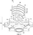
- FIG 2 is a different perspective view of the impeller shown in Figure 1 , with the mounting assembly 140 visible.
- the mounting assembly 140 is used to affix the impeller to an actuating means, such as a crank shaft driven by a gear box, as described in detail below.
- the mounting assembly can mount the impeller using a keyway connection, spline connection, threaded connection, bolt & nut connection, or any other mounting assembly known in the art.
- FIG 3 is a cross-sectional view of one embodiment of a two-stage centrifugal pump 200 comprising the one embodiment of the impeller of the present invention.
- the two stage pump comprises a first stage 206 a first inlet 216, which corresponds to the location of impeller eye 106. Fluid travels through inlet 216, through inducer section 102 and outlet section 104, and then flows into volute casing 210.
- the impeller is rotated about its axis of rotation by crank shaft 212 coupled to the impeller.
- Crank shaft 212 is turned by gear box 204.
- Volute casing 210 is in fluid communication with a fluid outlet channel (not shown, extending towards the viewer of the cross-section in Figure 3 ) which feeds the inlet 218 of the second stage 208 of the two-stage centrifugal pump 200. Fluid travels from the inlet through the second impeller and out through outlet volute casing 220.
- the second impeller is rotated about its axis of rotation by crank shaft 222, which is rotated by gear box 204.
- the second impeller is preferably not the inventive impeller described herein because the pressure at the inlet of the second stage inlet 218 is high enough that a conventional impeller can be used without causing cavitation or degradation of performance.
- the impeller of the present invention can be used in connection with virtually any centrifugal pump, such as a vertical single stage pump.
- the primary advantage the inventive impeller described herein provides to a practitioner is a reduction in cavitation during operation of the pump. Cavitation is caused by localized flow separation and backflow that would cause uneven acceleration in the fluid and, consequently, the formation of a vapor cavity at the location of the pressure drop. When the pressure inside the pump renormalizes, the vapor cavity is repressurized and implodes, causing damage to the surface of the impeller near the implosion. This has been found to occur at the inlet eye of the impeller, and for the impeller disclosed in US Patent 8,998,582 , at the leading edge of the radial blades comprising the outlet section, in the gap between the inducer blades and outlet blades.
- Cavitation is a major problem in centrifugal pumps, and can occur even when the pump is designed with a correctly designed impeller and adequate amount of suction head. It is difficult to prevent or eliminate from a design once it is found to exist.
- Known ways of dealing with cavitation include modifying inlet case geometry, volute style, inducer design, rounding blade corners, or reducing the speed of the impeller. These conventional methods usually fail to eliminate cavitation in the eye of the impeller.
- the present invention has been shown to substantially reduce or eliminate cavitation in the eye of the impeller, along the entire flow path of the impeller blades, and along the entire operating envelope of the pump, by not allowing recirculation, split flow, or backflow.
- the inventive impeller can be sized to retrofit with existing pump designs, and can be easily interchanged with the impeller provided with the original equipment design.
- the inventive impeller can be retrofitted onto existing pumps and allow for up to 120% of rated flow or best efficiency point (BEP) without causing cavitation damage.
Landscapes
- Engineering & Computer Science (AREA)
- Mechanical Engineering (AREA)
- General Engineering & Computer Science (AREA)
- Structures Of Non-Positive Displacement Pumps (AREA)
Description
- The present invention relates to an impeller for a centrifugal pump, the impeller being a combination axial and radial impeller that reduces cavitation and consequent damage during operation.
- Centrifugal pumps that utilize impeller blades are known in the art. Examples of centrifugal pumps and impeller blades can be seen in
US Patent 8,998,582 and European Patent Application No.89308869.0 DE 10050108 A1 discloses an impeller for a centrifugal pump comprising a bearing tube with an axial bore to receive a pump shaft and blades for guiding a liquid flow between a suction region and a pressure region. The main blades are canted at an angle from the axis of rotation, which is between 10 and 20°.FR 2962825 A1 - A centrifugal pump impeller according to the invention is defined in claim 1.
- In one embodiment, each outlet channel comprises a balance hole in its floor. In another embodiment according to any other embodiment or combination of embodiments, the centrifugal pump impeller comprises four main blades and four secondary blades. In another embodiment according to any other embodiment or combination of embodiments, the centrifugal pump further comprises a radial cutout between each main blade trailing edge and each secondary blade trailing edge, wherein the radial cutout comprises a section of the impeller comprising a third radius which is less than the first radius and the second radius.
- In another embodiment according to any other embodiment or combination of embodiments, each secondary blade is equidistant from each adjacent main blade from the secondary blade leading edge through to the secondary blade trailing edge.
- In another embodiment according to any other embodiment or combination of embodiments, each secondary blade is geometrically similar to an adjacent main blade region.
- In another embodiment according to any other embodiment or combination of embodiments, the transition region defines a continuous flow path between each inducer channel and the outlet end.
- In another embodiment according to any other embodiment or combination of embodiments, each secondary blade comprises a length that extends radially perpendicular from the axis of rotation, and a height that extends parallel to the axis of rotation.
- In another embodiment according to any other embodiment or combination of embodiments, the height of each secondary blade is equal to the height of each main blade.
- In another embodiment, a centrifugal pump comprises an impeller embodying any feature or combination of features described herein.
- The invention may be understood by reference to the following description taken in conjunction with the accompanying drawings, in which, like reference numerals identify like elements, and in which:
-
Figure 1 is a perspective view of one embodiment of the impeller of the present invention configured for use in a centrifugal pump; -
Figure 2 is a different perspective view of the same embodiment of the impeller of the present invention; -
Figure 3 is a cross-sectional view of a centrifugal pump comprising one embodiment of the impeller of the present invention. - One embodiment of the present invention is an impeller configured for use with a centrifugal pump, and another embodiment is a centrifugal pump comprising an impeller. The inventive impeller can be described as a combination axial impeller and radial impeller (or a two-stage impeller) because it comprises an inducer section (or first stage) that imparts axial flow to the fluid being pumped, and an outlet section (or second stage) that imparts radial flow to the fluid.
-
Figure 1 depicts a perspective view of one embodiment of the impeller of the present invention. Theimpeller 100 comprises aninducer end 102 and anoutlet end 104. As the impeller spins around its axis of rotation, fluid enters the pump chamber of the centrifugal pump near the inducer end of the impeller at theeye 106, gets accelerated by the impeller blades, and exits the pump chamber into the volute casing of the pump surrounding the impeller. - The impeller of the present invention comprises main blades 108 (sometimes referred to as vanes), which are continuous ridges that run from the inducer
end leading edge 118 to the outletend trailing edge 120. On theinducer end 102, themain blades 108 run in a helical path or spiral path from theleading edge 118 around the axis of rotation towards theoutlet end 104. In a section between theinducer end 102 and theoutlet end 104 is atransition region 114 in which themain blades 108 transition from a helical or spiral path to an axial/radial path. - The result is that each main blade comprises a
section 116 that extends radially, perpendicular to the axis of rotation of the impeller with ablade height 132 that is parallel to the axis of rotation, atransition section 114, and a section that is helical 102. Thesection 116 that is perpendicular to the axis of rotation extends from trailingedge 120 and ends at one end of thetransition section 114. Thetransition section 114 connects the helical orspiral inducer section 102 to thesection 116 that is perpendicular to the axis of rotation. - Prior art designs for impellers, such as the one shown in
US Patent 8,998,582 , comprise a gap or discontinuity in the blade between the inducer section and the outlet section. One difference between the present invention and the prior art is that eachmain blade 108 on the present invention is a continuous ridge from theleading edge 118 to the trailingedge 120. Consequently, there is a continuous inducer channel or flow path 126 (which is split into two channels or flow paths bysecondary blades 110, described in more detail below) from the leading edge of the inducer end to the transition section, and through to the outlet. This structure provides the fluid being pumped with a smooth transition from axial flow (flow in the axial direction) while in the inducer section to radial flow (flow in the radial direction) in the outlet section. - The
impeller 100 of the present invention also comprises at least onesecondary blade 110. Eachsecondary blade 110 comprises a trailingedge 124 that resembles the trailingedge 120 of themain blades 108. Thesecondary blade 110 comprises a ridge that extends from a trailingedge 124 to aleading edge 122. Theleading edge 122 of eachsecondary blade 110 is located between thetransition region 114 of each adjacentmain blade 108. Each secondary blade comprises a length that extends radially from the axis of rotation of the impeller, and a height that extends parallel to the axis of rotation. In a preferred embodiment, this portion of the secondary blade is geometrically similar to each adjacent region of each adjacentmain blade 108. Additionally, in one embodiment, each secondary blade is disposed on the impeller equidistant from each adjacent main blade. - Each secondary blade splits the
continuous inducer channel 126 defined by the main blades that are on either side of the secondary blade into twocontinuous outlet channels leading edge 122 of the secondary blade and circumferentially adjacent location on the adjacent main blade to an area between the trailing edge of the secondary blade and the trailing edge of the same main blade. Each outlet channel is defined by a first wall and a second wall, and a floor that connects the first wall to the second wall. The first wall comprises one surface of a main blade and the second wall comprises a surface of an adjacent secondary blade that faces the surface of the main blade that comprises the first wall. The floor is the surface of the impeller that connects the first wall with the second wall. One or both ofoutlet channels - In a preferred embodiment, each outlet channel comprises a
radial cutout 134 in the floor of the outlet channel. The radial cutout is a region where the outer edge at the outlet end of the impeller comprises a radius that is less than the radius of the impeller at the location of the trailing edge of the main blade or the trailing edge of the secondary blade. The radial cutouts help decrease axial load on the back side of the impeller, but cannot extend too far towards the axis of rotation or they will impact the structural integrity of the impeller blades. - In a preferred embodiment, the impeller comprises at least one
balance hole 112. Balance holes help equalize the pressure on the front and back of the impeller shroud. Omitting balance holes can cause too much pressure to develop behind the impeller, which increases the axial thrust loads and increases the risk of a failed bearing. -
Figure 2 is a different perspective view of the impeller shown inFigure 1 , with the mountingassembly 140 visible. The mountingassembly 140 is used to affix the impeller to an actuating means, such as a crank shaft driven by a gear box, as described in detail below. The mounting assembly can mount the impeller using a keyway connection, spline connection, threaded connection, bolt & nut connection, or any other mounting assembly known in the art. -
Figure 3 is a cross-sectional view of one embodiment of a two-stagecentrifugal pump 200 comprising the one embodiment of the impeller of the present invention. The two stage pump comprises a first stage 206 afirst inlet 216, which corresponds to the location ofimpeller eye 106. Fluid travels throughinlet 216, throughinducer section 102 andoutlet section 104, and then flows intovolute casing 210. The impeller is rotated about its axis of rotation by crankshaft 212 coupled to the impeller. Crankshaft 212 is turned bygear box 204. -
Volute casing 210 is in fluid communication with a fluid outlet channel (not shown, extending towards the viewer of the cross-section inFigure 3 ) which feeds theinlet 218 of thesecond stage 208 of the two-stagecentrifugal pump 200. Fluid travels from the inlet through the second impeller and out throughoutlet volute casing 220. The second impeller is rotated about its axis of rotation by crankshaft 222, which is rotated bygear box 204. The second impeller is preferably not the inventive impeller described herein because the pressure at the inlet of thesecond stage inlet 218 is high enough that a conventional impeller can be used without causing cavitation or degradation of performance. - Although the embodiment shown in
Figure 3 is a two-stage centrifugal pump, the impeller of the present invention can be used in connection with virtually any centrifugal pump, such as a vertical single stage pump. - The primary advantage the inventive impeller described herein provides to a practitioner is a reduction in cavitation during operation of the pump. Cavitation is caused by localized flow separation and backflow that would cause uneven acceleration in the fluid and, consequently, the formation of a vapor cavity at the location of the pressure drop. When the pressure inside the pump renormalizes, the vapor cavity is repressurized and implodes, causing damage to the surface of the impeller near the implosion. This has been found to occur at the inlet eye of the impeller, and for the impeller disclosed in
US Patent 8,998,582 , at the leading edge of the radial blades comprising the outlet section, in the gap between the inducer blades and outlet blades. - Cavitation is a major problem in centrifugal pumps, and can occur even when the pump is designed with a correctly designed impeller and adequate amount of suction head. It is difficult to prevent or eliminate from a design once it is found to exist. Known ways of dealing with cavitation include modifying inlet case geometry, volute style, inducer design, rounding blade corners, or reducing the speed of the impeller. These conventional methods usually fail to eliminate cavitation in the eye of the impeller.
- The present invention has been shown to substantially reduce or eliminate cavitation in the eye of the impeller, along the entire flow path of the impeller blades, and along the entire operating envelope of the pump, by not allowing recirculation, split flow, or backflow. In one embodiment, the inventive impeller can be sized to retrofit with existing pump designs, and can be easily interchanged with the impeller provided with the original equipment design. The inventive impeller can be retrofitted onto existing pumps and allow for up to 120% of rated flow or best efficiency point (BEP) without causing cavitation damage.
- While the invention is susceptible to various modifications and alternative forms, specific embodiments thereof have been shown by way of example in the drawings and are herein described in detail. It should be understood, however, that the description herein of specific embodiments is not intended to limit the invention to the particular forms disclosed. The invention is solely defined by the appended claims.
Claims (10)
- A centrifugal pump impeller (100) comprising:an axis of rotation;an inducer end opposite from an outlet end along the axis of rotation;at least two main blades (108);at least two secondary blades (110);wherein the inducer end comprises an inlet eye (106);wherein each main blade is a continuous ridge extending from a main blade leading edge (118) to a main blade trailing edge (120);wherein each main blade leading edge is adjacent to the inlet eye and each main blade trailing edge defines a first radius of the outlet end;wherein each main blade comprises a transition region between the inducer end and the outlet end, such that each main blade comprises an inducer end section (102), a transition section (114), and an outlet end section (116);wherein in the inducer end section (102), each main blade follows a helical or spiral path around the axis of rotation from the main blade leading edge in (118) towards the transition section (114), and wherein each main blade defines a continuous inducer channel (126) between itself and an adjacent main blade;wherein the outlet end section (116) extends radially, perpendicular to the axis of rotation with a blade height (132) that is parallel to the axis of rotation, extends from the main blade trailing edge , and ends the transition section (114);wherein each secondary blade is a continuous ridge extending from a secondary blade leading edge (122) to a secondary blade trailing edge (124);wherein each secondary blade leading edge is disposed between two adjacent transition regions of each of two adjacent main blades;wherein each secondary blade trailing edge defines a second radius of the outlet end which is equal to the first radius of the outlet end;wherein each secondary blade defines two outlet channels (128, 130), wherein each outlet channel is defined by a first wall, a second wall and a floor that connects the first wall with the second wall, wherein the first wall of each outlet channel is one surface of a secondary blade and the second wall of each outlet channel is a surface of an adjacent main blade that faces the surface of the secondary blade defining the first wall, wherein the floor of each outlet channel is the surface of the impeller connecting the first wall to the second wall.
- The centrifugal pump impeller (100) of claim 1 wherein each outlet channel (128, 130) comprises a balance hole (112) in its floor.
- The centrifugal pump impeller (100) of claim 1 comprising four main blades (108) and four secondary blades (110).
- The centrifugal pump impeller (100) of claim 1 further comprising a radial cutout (134) between each main blade trailing edge (120) and each secondary blade trailing edge (124), wherein the radial cutout comprises a section of the impeller comprising a third radius which is less than the first radius and the second radius.
- The centrifugal pump impeller (100) of claim 1 wherein each secondary blade (110) is equidistant from each adjacent main blade (108) from the secondary blade leading edge (122) through to the secondary blade trailing edge (124).
- The centrifugal pump impeller (100) of claim 1 wherein each secondary blade (110) is geometrically similar to an adjacent main blade region (116).
- The centrifugal pump impeller (100) of claim 1 wherein the transition region (114) defines a continuous flow path between each inducer channel (126) and the outlet end (104).
- The centrifugal pump impeller (100) of claim 1 wherein each secondary blade (110) comprises a length that extends radially perpendicular from the axis of rotation, and a height that extends parallel to the axis of rotation.
- The centrifugal pump impeller of claim 1 wherein the height of each secondary blade (110) is equal to the height (132) of each main blade (108).
- A centrifugal pump (200) comprising the impeller (100) of claim 1.
Applications Claiming Priority (2)
| Application Number | Priority Date | Filing Date | Title |
|---|---|---|---|
| US14/874,166 US10001133B2 (en) | 2015-10-02 | 2015-10-02 | Low-cavitation impeller and pump |
| PCT/US2016/054454 WO2017059074A1 (en) | 2015-10-02 | 2016-09-29 | Low-cavitation impeller and pump |
Publications (3)
| Publication Number | Publication Date |
|---|---|
| EP3356682A1 EP3356682A1 (en) | 2018-08-08 |
| EP3356682A4 EP3356682A4 (en) | 2019-06-05 |
| EP3356682B1 true EP3356682B1 (en) | 2021-05-05 |
Family
ID=58424350
Family Applications (1)
| Application Number | Title | Priority Date | Filing Date |
|---|---|---|---|
| EP16852599.6A Active EP3356682B1 (en) | 2015-10-02 | 2016-09-29 | Low-cavitation impeller and pump |
Country Status (8)
| Country | Link |
|---|---|
| US (1) | US10001133B2 (en) |
| EP (1) | EP3356682B1 (en) |
| JP (1) | JP6510141B2 (en) |
| KR (1) | KR101876164B1 (en) |
| CN (1) | CN108350907B (en) |
| HK (1) | HK1251635B (en) |
| RU (1) | RU2681868C1 (en) |
| WO (1) | WO2017059074A1 (en) |
Families Citing this family (17)
| Publication number | Priority date | Publication date | Assignee | Title |
|---|---|---|---|---|
| TWI725016B (en) * | 2015-03-20 | 2021-04-21 | 日商荏原製作所股份有限公司 | Impeller for centrifugal pumps |
| CN108005949B (en) * | 2017-07-18 | 2024-05-14 | 宁波方太厨具有限公司 | Impeller of open type water pump |
| JP6718584B2 (en) * | 2018-01-26 | 2020-07-08 | Smc株式会社 | Fluid pressure cylinder |
| TWI675995B (en) * | 2018-03-30 | 2019-11-01 | 合利美股份有限公司 | Drainage impeller |
| US20190345955A1 (en) * | 2018-05-10 | 2019-11-14 | Mp Pumps Inc. | Impeller pump |
| CA3048275A1 (en) * | 2019-06-28 | 2020-12-28 | Nicholas James GUENTHER | Inducer for a submersible pump for pumping a pumping media containing solids and viscous fluids and method of manufacturing same |
| FR3112812B1 (en) * | 2020-07-24 | 2022-07-29 | Safran Aircraft Engines | Improved fuel pump for aircraft engine |
| JP2022056948A (en) * | 2020-09-30 | 2022-04-11 | 株式会社豊田自動織機 | Centrifugal compressor |
| WO2022099845A1 (en) * | 2020-11-12 | 2022-05-19 | 威灵(芜湖)电机制造有限公司 | Impeller, drainage pump, and air-conditioning indoor unit |
| KR102921813B1 (en) * | 2021-03-30 | 2026-02-03 | 삼성전자주식회사 | Motor and cleaner having the same |
| KR200494301Y1 (en) * | 2021-05-06 | 2021-09-10 | 주식회사 대영파워펌프 | Impeller for submersible pump |
| CN217360731U (en) * | 2021-08-26 | 2022-09-02 | 春鸿电子科技(重庆)有限公司 | Two-phase cold plate |
| CN114109910B (en) * | 2021-12-01 | 2023-07-14 | 广东泰极动力科技有限公司 | Self-priming centrifugal high-pressure fan |
| KR102506982B1 (en) | 2022-10-06 | 2023-03-07 | 주식회사 신성터보마스터 | Inflow redemption system |
| TWI884410B (en) * | 2023-01-12 | 2025-05-21 | 弓銓企業股份有限公司 | Electronic water meter and its impeller with pressure relief function |
| US12480497B2 (en) * | 2023-05-25 | 2025-11-25 | Flowserve Us Company | Modular cryogenic permanent magnet electrical motors and generators for submerged motor pumps and turbines and related systems and methods |
| US12584488B2 (en) | 2024-05-24 | 2026-03-24 | Flowserve Us Company | Balance drums and systems for managing axial forces for pumps and related systems and methods |
Family Cites Families (20)
| Publication number | Priority date | Publication date | Assignee | Title |
|---|---|---|---|---|
| US3737249A (en) * | 1970-08-26 | 1973-06-05 | Trw Inc | High flow pump impeller for low net positive suction head and method of designing same |
| US3953150A (en) * | 1972-02-10 | 1976-04-27 | Sundstrand Corporation | Impeller apparatus |
| US4481020A (en) * | 1982-06-10 | 1984-11-06 | Trw Inc. | Liquid-gas separator apparatus |
| US4890980A (en) * | 1988-08-08 | 1990-01-02 | Ingersoll-Rand Company | Centrifugal pump |
| GB8821729D0 (en) | 1988-09-16 | 1988-11-16 | Nat Nuclear Corp Ltd | Impeller pumps |
| JPH02118195U (en) * | 1989-03-10 | 1990-09-21 | ||
| WO2001016491A1 (en) * | 1999-09-01 | 2001-03-08 | Coltec Industries, Inc. | Centrifugal pump |
| DE10050108A1 (en) * | 2000-10-09 | 2002-06-06 | Allweiler Ag | Rotor for turbine pump has bearing tube with bore to receive shaft and even number of vanes formed on it |
| EP1325232B1 (en) * | 2000-10-09 | 2006-08-23 | Allweiler AG | Centrifugal wheel pump |
| CN2558799Y (en) * | 2002-06-19 | 2003-07-02 | 中国航天科技集团公司第十一研究所(京) | Impeller structure for increasing cavitation resistance of low specific speed centrifugal pump |
| JP3876195B2 (en) * | 2002-07-05 | 2007-01-31 | 本田技研工業株式会社 | Centrifugal compressor impeller |
| US7461692B1 (en) * | 2005-12-15 | 2008-12-09 | Wood Group Esp, Inc. | Multi-stage gas separator |
| US8506236B2 (en) * | 2009-08-03 | 2013-08-13 | Ebara International Corporation | Counter rotation inducer housing |
| WO2012002107A1 (en) * | 2010-06-30 | 2012-01-05 | アイシン精機株式会社 | Impeller and method for producing same |
| FR2962825A1 (en) * | 2010-07-16 | 2012-01-20 | Pierre Carrouset | Turbomachine configuring and constructing method for engineering and design department, involves projecting straight lines from points of body leading edge and blade trailing edge in continuity of trajectories of leading and trailing edges |
| US8998582B2 (en) * | 2010-11-15 | 2015-04-07 | Sundyne, Llc | Flow vector control for high speed centrifugal pumps |
| US8936430B2 (en) * | 2011-04-19 | 2015-01-20 | Halliburton Energy Services, Inc. | Submersible centrifugal pump for solids-laden fluid |
| US8944767B2 (en) * | 2012-01-17 | 2015-02-03 | Hamilton Sundstrand Corporation | Fuel system centrifugal boost pump impeller |
| RU2511967C1 (en) * | 2013-04-22 | 2014-04-10 | Открытое акционерное общество "ЭНТЕХНО" | Turbo-pump unit, and cold, hot and industrial water pumping method |
| RU152113U1 (en) * | 2014-05-08 | 2015-05-10 | Федеральное государственное бюджетное образовательное учреждение высшего профессионального образования "Московский государственный технический университет имени Н.Э. Баумана" (МГТУ им. Н.Э. Баумана) | ANTI-CAVITATION SECOND-CENTRIFUGAL WORKING WHEEL OF THE CIRCULATION PUMP FOR A HIGH-TEMPERATURE HEAT |
-
2015
- 2015-10-02 US US14/874,166 patent/US10001133B2/en active Active
-
2016
- 2016-09-29 RU RU2018113487A patent/RU2681868C1/en active
- 2016-09-29 KR KR1020187011998A patent/KR101876164B1/en active Active
- 2016-09-29 WO PCT/US2016/054454 patent/WO2017059074A1/en not_active Ceased
- 2016-09-29 EP EP16852599.6A patent/EP3356682B1/en active Active
- 2016-09-29 JP JP2018516706A patent/JP6510141B2/en active Active
- 2016-09-29 CN CN201680066597.7A patent/CN108350907B/en active Active
- 2016-09-29 HK HK18110850.8A patent/HK1251635B/en unknown
Also Published As
| Publication number | Publication date |
|---|---|
| US10001133B2 (en) | 2018-06-19 |
| JP2018529880A (en) | 2018-10-11 |
| KR101876164B1 (en) | 2018-07-06 |
| RU2681868C1 (en) | 2019-03-13 |
| CN108350907B (en) | 2019-07-12 |
| JP6510141B2 (en) | 2019-05-08 |
| EP3356682A1 (en) | 2018-08-08 |
| EP3356682A4 (en) | 2019-06-05 |
| WO2017059074A1 (en) | 2017-04-06 |
| CN108350907A (en) | 2018-07-31 |
| HK1251635B (en) | 2020-04-24 |
| US20170097008A1 (en) | 2017-04-06 |
| KR20180054850A (en) | 2018-05-24 |
Similar Documents
| Publication | Publication Date | Title |
|---|---|---|
| US10001133B2 (en) | Low-cavitation impeller and pump | |
| HK1251635A1 (en) | Low-cavitation impeller and pump | |
| US8801360B2 (en) | Centrifugal pump with thrust balance holes in diffuser | |
| EP3207260B1 (en) | Impeller assembly especially for centrifugal pumps | |
| US8998582B2 (en) | Flow vector control for high speed centrifugal pumps | |
| US9835161B2 (en) | Rotary machine | |
| JP6793254B2 (en) | High efficiency double suction impeller | |
| EP2535596B1 (en) | Centrifugal compressor using an asymmetric self-recirculating casing treatment | |
| EP3401550B1 (en) | Volute casing for a centrifugal pump and centrifugal pump | |
| US10670025B2 (en) | Centrifugal compressor | |
| JP2012202260A (en) | Impeller and turbo machine including the same | |
| US20170037866A1 (en) | Impeller and rotating machine provided with same | |
| KR20150032686A (en) | Device for guiding impeller suction of centrifugal pump | |
| US20150354588A1 (en) | Centrifugal compressor | |
| EP4477892A1 (en) | Centrifugal pump for conveying a fluid | |
| CN205089696U (en) | Anti -cavitation centrifugal pump | |
| HK1259557A1 (en) | Low-cavitation impeller and pump | |
| HK1259557B (en) | Low-cavitation impeller and pump | |
| US20170350410A1 (en) | Centrifugal compressor impeller | |
| EP3828417B1 (en) | Bridged stage piece | |
| CA2715953C (en) | Centrifugal pump with thrust balance holes in diffuser | |
| EP2535595A1 (en) | Centrifugal compressor using an asymmetric self-recirculating casing treatment | |
| KR20130112477A (en) | Centrifugal pump | |
| EP2503156A1 (en) | Impeller for centrifugal pump | |
| WO2016007317A1 (en) | Turbopump with axially curved vane |
Legal Events
| Date | Code | Title | Description |
|---|---|---|---|
| STAA | Information on the status of an ep patent application or granted ep patent |
Free format text: STATUS: THE INTERNATIONAL PUBLICATION HAS BEEN MADE |
|
| PUAI | Public reference made under article 153(3) epc to a published international application that has entered the european phase |
Free format text: ORIGINAL CODE: 0009012 |
|
| STAA | Information on the status of an ep patent application or granted ep patent |
Free format text: STATUS: REQUEST FOR EXAMINATION WAS MADE |
|
| 17P | Request for examination filed |
Effective date: 20180430 |
|
| AK | Designated contracting states |
Kind code of ref document: A1 Designated state(s): AL AT BE BG CH CY CZ DE DK EE ES FI FR GB GR HR HU IE IS IT LI LT LU LV MC MK MT NL NO PL PT RO RS SE SI SK SM TR |
|
| AX | Request for extension of the european patent |
Extension state: BA ME |
|
| DAV | Request for validation of the european patent (deleted) | ||
| DAX | Request for extension of the european patent (deleted) | ||
| REG | Reference to a national code |
Ref country code: DE Ref legal event code: R079 Ref document number: 602016057551 Country of ref document: DE Free format text: PREVIOUS MAIN CLASS: F04D0029660000 Ipc: F04D0029220000 |
|
| A4 | Supplementary search report drawn up and despatched |
Effective date: 20190506 |
|
| RIC1 | Information provided on ipc code assigned before grant |
Ipc: F04D 29/22 20060101AFI20190429BHEP |
|
| REG | Reference to a national code |
Ref country code: HK Ref legal event code: DE Ref document number: 1259557 Country of ref document: HK |
|
| STAA | Information on the status of an ep patent application or granted ep patent |
Free format text: STATUS: EXAMINATION IS IN PROGRESS |
|
| 17Q | First examination report despatched |
Effective date: 20200213 |
|
| GRAP | Despatch of communication of intention to grant a patent |
Free format text: ORIGINAL CODE: EPIDOSNIGR1 |
|
| STAA | Information on the status of an ep patent application or granted ep patent |
Free format text: STATUS: GRANT OF PATENT IS INTENDED |
|
| INTG | Intention to grant announced |
Effective date: 20201216 |
|
| GRAS | Grant fee paid |
Free format text: ORIGINAL CODE: EPIDOSNIGR3 |
|
| GRAA | (expected) grant |
Free format text: ORIGINAL CODE: 0009210 |
|
| STAA | Information on the status of an ep patent application or granted ep patent |
Free format text: STATUS: THE PATENT HAS BEEN GRANTED |
|
| AK | Designated contracting states |
Kind code of ref document: B1 Designated state(s): AL AT BE BG CH CY CZ DE DK EE ES FI FR GB GR HR HU IE IS IT LI LT LU LV MC MK MT NL NO PL PT RO RS SE SI SK SM TR |
|
| REG | Reference to a national code |
Ref country code: GB Ref legal event code: FG4D |
|
| REG | Reference to a national code |
Ref country code: CH Ref legal event code: EP |
|
| REG | Reference to a national code |
Ref country code: AT Ref legal event code: REF Ref document number: 1390150 Country of ref document: AT Kind code of ref document: T Effective date: 20210515 |
|
| REG | Reference to a national code |
Ref country code: DE Ref legal event code: R096 Ref document number: 602016057551 Country of ref document: DE |
|
| REG | Reference to a national code |
Ref country code: IE Ref legal event code: FG4D |
|
| REG | Reference to a national code |
Ref country code: LT Ref legal event code: MG9D |
|
| REG | Reference to a national code |
Ref country code: AT Ref legal event code: MK05 Ref document number: 1390150 Country of ref document: AT Kind code of ref document: T Effective date: 20210505 |
|
| PG25 | Lapsed in a contracting state [announced via postgrant information from national office to epo] |
Ref country code: HR Free format text: LAPSE BECAUSE OF FAILURE TO SUBMIT A TRANSLATION OF THE DESCRIPTION OR TO PAY THE FEE WITHIN THE PRESCRIBED TIME-LIMIT Effective date: 20210505 Ref country code: AT Free format text: LAPSE BECAUSE OF FAILURE TO SUBMIT A TRANSLATION OF THE DESCRIPTION OR TO PAY THE FEE WITHIN THE PRESCRIBED TIME-LIMIT Effective date: 20210505 Ref country code: BG Free format text: LAPSE BECAUSE OF FAILURE TO SUBMIT A TRANSLATION OF THE DESCRIPTION OR TO PAY THE FEE WITHIN THE PRESCRIBED TIME-LIMIT Effective date: 20210805 Ref country code: FI Free format text: LAPSE BECAUSE OF FAILURE TO SUBMIT A TRANSLATION OF THE DESCRIPTION OR TO PAY THE FEE WITHIN THE PRESCRIBED TIME-LIMIT Effective date: 20210505 Ref country code: LT Free format text: LAPSE BECAUSE OF FAILURE TO SUBMIT A TRANSLATION OF THE DESCRIPTION OR TO PAY THE FEE WITHIN THE PRESCRIBED TIME-LIMIT Effective date: 20210505 |
|
| PG25 | Lapsed in a contracting state [announced via postgrant information from national office to epo] |
Ref country code: NO Free format text: LAPSE BECAUSE OF FAILURE TO SUBMIT A TRANSLATION OF THE DESCRIPTION OR TO PAY THE FEE WITHIN THE PRESCRIBED TIME-LIMIT Effective date: 20210805 Ref country code: PL Free format text: LAPSE BECAUSE OF FAILURE TO SUBMIT A TRANSLATION OF THE DESCRIPTION OR TO PAY THE FEE WITHIN THE PRESCRIBED TIME-LIMIT Effective date: 20210505 Ref country code: PT Free format text: LAPSE BECAUSE OF FAILURE TO SUBMIT A TRANSLATION OF THE DESCRIPTION OR TO PAY THE FEE WITHIN THE PRESCRIBED TIME-LIMIT Effective date: 20210906 Ref country code: RS Free format text: LAPSE BECAUSE OF FAILURE TO SUBMIT A TRANSLATION OF THE DESCRIPTION OR TO PAY THE FEE WITHIN THE PRESCRIBED TIME-LIMIT Effective date: 20210505 Ref country code: SE Free format text: LAPSE BECAUSE OF FAILURE TO SUBMIT A TRANSLATION OF THE DESCRIPTION OR TO PAY THE FEE WITHIN THE PRESCRIBED TIME-LIMIT Effective date: 20210505 Ref country code: GR Free format text: LAPSE BECAUSE OF FAILURE TO SUBMIT A TRANSLATION OF THE DESCRIPTION OR TO PAY THE FEE WITHIN THE PRESCRIBED TIME-LIMIT Effective date: 20210806 Ref country code: LV Free format text: LAPSE BECAUSE OF FAILURE TO SUBMIT A TRANSLATION OF THE DESCRIPTION OR TO PAY THE FEE WITHIN THE PRESCRIBED TIME-LIMIT Effective date: 20210505 Ref country code: IS Free format text: LAPSE BECAUSE OF FAILURE TO SUBMIT A TRANSLATION OF THE DESCRIPTION OR TO PAY THE FEE WITHIN THE PRESCRIBED TIME-LIMIT Effective date: 20210905 |
|
| REG | Reference to a national code |
Ref country code: NL Ref legal event code: MP Effective date: 20210505 |
|
| PG25 | Lapsed in a contracting state [announced via postgrant information from national office to epo] |
Ref country code: NL Free format text: LAPSE BECAUSE OF FAILURE TO SUBMIT A TRANSLATION OF THE DESCRIPTION OR TO PAY THE FEE WITHIN THE PRESCRIBED TIME-LIMIT Effective date: 20210505 |
|
| PG25 | Lapsed in a contracting state [announced via postgrant information from national office to epo] |
Ref country code: ES Free format text: LAPSE BECAUSE OF FAILURE TO SUBMIT A TRANSLATION OF THE DESCRIPTION OR TO PAY THE FEE WITHIN THE PRESCRIBED TIME-LIMIT Effective date: 20210505 Ref country code: RO Free format text: LAPSE BECAUSE OF FAILURE TO SUBMIT A TRANSLATION OF THE DESCRIPTION OR TO PAY THE FEE WITHIN THE PRESCRIBED TIME-LIMIT Effective date: 20210505 Ref country code: CZ Free format text: LAPSE BECAUSE OF FAILURE TO SUBMIT A TRANSLATION OF THE DESCRIPTION OR TO PAY THE FEE WITHIN THE PRESCRIBED TIME-LIMIT Effective date: 20210505 Ref country code: DK Free format text: LAPSE BECAUSE OF FAILURE TO SUBMIT A TRANSLATION OF THE DESCRIPTION OR TO PAY THE FEE WITHIN THE PRESCRIBED TIME-LIMIT Effective date: 20210505 Ref country code: EE Free format text: LAPSE BECAUSE OF FAILURE TO SUBMIT A TRANSLATION OF THE DESCRIPTION OR TO PAY THE FEE WITHIN THE PRESCRIBED TIME-LIMIT Effective date: 20210505 Ref country code: SK Free format text: LAPSE BECAUSE OF FAILURE TO SUBMIT A TRANSLATION OF THE DESCRIPTION OR TO PAY THE FEE WITHIN THE PRESCRIBED TIME-LIMIT Effective date: 20210505 Ref country code: SM Free format text: LAPSE BECAUSE OF FAILURE TO SUBMIT A TRANSLATION OF THE DESCRIPTION OR TO PAY THE FEE WITHIN THE PRESCRIBED TIME-LIMIT Effective date: 20210505 |
|
| REG | Reference to a national code |
Ref country code: DE Ref legal event code: R097 Ref document number: 602016057551 Country of ref document: DE |
|
| PLBE | No opposition filed within time limit |
Free format text: ORIGINAL CODE: 0009261 |
|
| STAA | Information on the status of an ep patent application or granted ep patent |
Free format text: STATUS: NO OPPOSITION FILED WITHIN TIME LIMIT |
|
| REG | Reference to a national code |
Ref country code: DE Ref legal event code: R119 Ref document number: 602016057551 Country of ref document: DE |
|
| 26N | No opposition filed |
Effective date: 20220208 |
|
| REG | Reference to a national code |
Ref country code: CH Ref legal event code: PL |
|
| PG25 | Lapsed in a contracting state [announced via postgrant information from national office to epo] |
Ref country code: IS Free format text: LAPSE BECAUSE OF FAILURE TO SUBMIT A TRANSLATION OF THE DESCRIPTION OR TO PAY THE FEE WITHIN THE PRESCRIBED TIME-LIMIT Effective date: 20210905 Ref country code: MC Free format text: LAPSE BECAUSE OF FAILURE TO SUBMIT A TRANSLATION OF THE DESCRIPTION OR TO PAY THE FEE WITHIN THE PRESCRIBED TIME-LIMIT Effective date: 20210505 Ref country code: AL Free format text: LAPSE BECAUSE OF FAILURE TO SUBMIT A TRANSLATION OF THE DESCRIPTION OR TO PAY THE FEE WITHIN THE PRESCRIBED TIME-LIMIT Effective date: 20210505 |
|
| PG25 | Lapsed in a contracting state [announced via postgrant information from national office to epo] |
Ref country code: LU Free format text: LAPSE BECAUSE OF NON-PAYMENT OF DUE FEES Effective date: 20210929 Ref country code: IT Free format text: LAPSE BECAUSE OF FAILURE TO SUBMIT A TRANSLATION OF THE DESCRIPTION OR TO PAY THE FEE WITHIN THE PRESCRIBED TIME-LIMIT Effective date: 20210505 Ref country code: IE Free format text: LAPSE BECAUSE OF NON-PAYMENT OF DUE FEES Effective date: 20210929 Ref country code: FR Free format text: LAPSE BECAUSE OF NON-PAYMENT OF DUE FEES Effective date: 20210930 Ref country code: DE Free format text: LAPSE BECAUSE OF NON-PAYMENT OF DUE FEES Effective date: 20220401 |
|
| PG25 | Lapsed in a contracting state [announced via postgrant information from national office to epo] |
Ref country code: LI Free format text: LAPSE BECAUSE OF NON-PAYMENT OF DUE FEES Effective date: 20210930 Ref country code: CH Free format text: LAPSE BECAUSE OF NON-PAYMENT OF DUE FEES Effective date: 20210930 |
|
| PG25 | Lapsed in a contracting state [announced via postgrant information from national office to epo] |
Ref country code: CY Free format text: LAPSE BECAUSE OF FAILURE TO SUBMIT A TRANSLATION OF THE DESCRIPTION OR TO PAY THE FEE WITHIN THE PRESCRIBED TIME-LIMIT Effective date: 20210505 |
|
| PG25 | Lapsed in a contracting state [announced via postgrant information from national office to epo] |
Ref country code: HU Free format text: LAPSE BECAUSE OF FAILURE TO SUBMIT A TRANSLATION OF THE DESCRIPTION OR TO PAY THE FEE WITHIN THE PRESCRIBED TIME-LIMIT; INVALID AB INITIO Effective date: 20160929 |
|
| PG25 | Lapsed in a contracting state [announced via postgrant information from national office to epo] |
Ref country code: MK Free format text: LAPSE BECAUSE OF FAILURE TO SUBMIT A TRANSLATION OF THE DESCRIPTION OR TO PAY THE FEE WITHIN THE PRESCRIBED TIME-LIMIT Effective date: 20210505 |
|
| PG25 | Lapsed in a contracting state [announced via postgrant information from national office to epo] |
Ref country code: MT Free format text: LAPSE BECAUSE OF FAILURE TO SUBMIT A TRANSLATION OF THE DESCRIPTION OR TO PAY THE FEE WITHIN THE PRESCRIBED TIME-LIMIT Effective date: 20210505 |
|
| PGFP | Annual fee paid to national office [announced via postgrant information from national office to epo] |
Ref country code: TR Payment date: 20250908 Year of fee payment: 10 |
|
| PGFP | Annual fee paid to national office [announced via postgrant information from national office to epo] |
Ref country code: BE Payment date: 20250925 Year of fee payment: 10 Ref country code: GB Payment date: 20250923 Year of fee payment: 10 |