EP3355504A1 - Method and device for adaptive streaming of multimedia data - Google Patents
Method and device for adaptive streaming of multimedia data Download PDFInfo
- Publication number
- EP3355504A1 EP3355504A1 EP17163335.7A EP17163335A EP3355504A1 EP 3355504 A1 EP3355504 A1 EP 3355504A1 EP 17163335 A EP17163335 A EP 17163335A EP 3355504 A1 EP3355504 A1 EP 3355504A1
- Authority
- EP
- European Patent Office
- Prior art keywords
- multimedia data
- media device
- packets
- data
- streaming
- Prior art date
- Legal status (The legal status is an assumption and is not a legal conclusion. Google has not performed a legal analysis and makes no representation as to the accuracy of the status listed.)
- Granted
Links
Images



Classifications
-
- H—ELECTRICITY
- H04—ELECTRIC COMMUNICATION TECHNIQUE
- H04L—TRANSMISSION OF DIGITAL INFORMATION, e.g. TELEGRAPHIC COMMUNICATION
- H04L65/00—Network arrangements, protocols or services for supporting real-time applications in data packet communication
- H04L65/60—Network streaming of media packets
- H04L65/61—Network streaming of media packets for supporting one-way streaming services, e.g. Internet radio
- H04L65/613—Network streaming of media packets for supporting one-way streaming services, e.g. Internet radio for the control of the source by the destination
-
- H—ELECTRICITY
- H04—ELECTRIC COMMUNICATION TECHNIQUE
- H04L—TRANSMISSION OF DIGITAL INFORMATION, e.g. TELEGRAPHIC COMMUNICATION
- H04L1/00—Arrangements for detecting or preventing errors in the information received
- H04L1/0001—Systems modifying transmission characteristics according to link quality, e.g. power backoff
- H04L1/0015—Systems modifying transmission characteristics according to link quality, e.g. power backoff characterised by the adaptation strategy
- H04L1/0017—Systems modifying transmission characteristics according to link quality, e.g. power backoff characterised by the adaptation strategy where the mode-switching is based on Quality of Service requirement
-
- H—ELECTRICITY
- H04—ELECTRIC COMMUNICATION TECHNIQUE
- H04L—TRANSMISSION OF DIGITAL INFORMATION, e.g. TELEGRAPHIC COMMUNICATION
- H04L43/00—Arrangements for monitoring or testing data switching networks
- H04L43/08—Monitoring or testing based on specific metrics, e.g. QoS, energy consumption or environmental parameters
- H04L43/0823—Errors, e.g. transmission errors
- H04L43/0847—Transmission error
-
- H—ELECTRICITY
- H04—ELECTRIC COMMUNICATION TECHNIQUE
- H04L—TRANSMISSION OF DIGITAL INFORMATION, e.g. TELEGRAPHIC COMMUNICATION
- H04L43/00—Arrangements for monitoring or testing data switching networks
- H04L43/08—Monitoring or testing based on specific metrics, e.g. QoS, energy consumption or environmental parameters
- H04L43/0852—Delays
- H04L43/087—Jitter
-
- H—ELECTRICITY
- H04—ELECTRIC COMMUNICATION TECHNIQUE
- H04L—TRANSMISSION OF DIGITAL INFORMATION, e.g. TELEGRAPHIC COMMUNICATION
- H04L43/00—Arrangements for monitoring or testing data switching networks
- H04L43/08—Monitoring or testing based on specific metrics, e.g. QoS, energy consumption or environmental parameters
- H04L43/0876—Network utilisation, e.g. volume of load or congestion level
- H04L43/0894—Packet rate
-
- H—ELECTRICITY
- H04—ELECTRIC COMMUNICATION TECHNIQUE
- H04L—TRANSMISSION OF DIGITAL INFORMATION, e.g. TELEGRAPHIC COMMUNICATION
- H04L47/00—Traffic control in data switching networks
- H04L47/10—Flow control; Congestion control
- H04L47/12—Avoiding congestion; Recovering from congestion
- H04L47/125—Avoiding congestion; Recovering from congestion by balancing the load, e.g. traffic engineering
-
- H—ELECTRICITY
- H04—ELECTRIC COMMUNICATION TECHNIQUE
- H04L—TRANSMISSION OF DIGITAL INFORMATION, e.g. TELEGRAPHIC COMMUNICATION
- H04L65/00—Network arrangements, protocols or services for supporting real-time applications in data packet communication
- H04L65/80—Responding to QoS
-
- H—ELECTRICITY
- H04—ELECTRIC COMMUNICATION TECHNIQUE
- H04L—TRANSMISSION OF DIGITAL INFORMATION, e.g. TELEGRAPHIC COMMUNICATION
- H04L1/00—Arrangements for detecting or preventing errors in the information received
- H04L2001/0092—Error control systems characterised by the topology of the transmission link
- H04L2001/0096—Channel splitting in point-to-point links
Definitions
- the present disclosure relates to streaming multimedia data. Particularly but not exclusively, the present invention relates to a method and a device for streaming multimedia data over multiple network interfaces.
- Live streaming is a process of streaming media in real-time by collecting media files from a provider.
- Media may be audio files or video files.
- Live video streaming is very popular as various media devices support downloading the media files in real-time.
- a video can be streamed in many qualities, for example, 144p, 240p, 360p, 480p, 720p, 1080p, etc.
- video streaming of qualities 144p, 240p, 360p and 480p provide low picture quality and require less Internet bandwidth and low data rate for downloading the media files.
- Video streaming of qualities 720p, 1080p and higher resolution video streaming provide high picture quality and require high bandwidth and high data rate for downloading the media files.
- multiple network interface may be cellular network, Wireless Fidelity (Wi-Fi) network and Bluetooth tethering.
- the conventional systems download the media files on each of the multiple interfaces.
- the media files are divided into packets.
- the packets are received from at least one network interface from the multiple interfaces.
- a packet is received from each of the network interfaces, thus causing repetition of the packets.
- additional memory may be required to store the packets.
- the conventional systems may not be feasible for applications having memory constraints.
- device transmitting the packets and device receiving the packets may consume more power for transmitting and receiving the same packets respectively.
- the present disclosure provides a method for adaptive streaming of multimedia data.
- the method comprises receiving, by a media device, a request for streaming a multimedia data, identifying network interfaces available in the media device, allocating data packets to the network interfaces based on one or more bandwidth parameters of the network interfaces, and requesting the data packets of the multimedia data over the allocated interfaces, for adaptively streaming the multimedia data on the media device.
- the present disclosure provides a device for adaptive streaming of multimedia data.
- the device comprises a processor and a memory communicatively connected to the processor.
- the processor is configured to receive a request for streaming a multimedia data, identify network interfaces available in the media device, allocate data packets to the network interfaces based on one or more bandwidth parameters of the network interfaces, and request the data packets of the multimedia data over the allocated interfaces, for adaptively streaming the multimedia data on the media device.
- the present disclosure relates to a non-transitory computer readable medium including instructions stored thereon that when processed by at least one processor cause a device to perform operations comprising, receiving a request for streaming a multimedia data, wherein the multimedia data is divided into a plurality of data packets, identifying network interfaces available in the media device, allocating data packets from the plurality of data packets to the network interfaces based on one or more bandwidth parameters of the network interfaces, and requesting the data packets of the multimedia data over the allocated interfaces, for adaptively streaming the multimedia data on the media device.
- Embodiments of the present disclosure relate to a method and a device for adaptive streaming of multimedia data.
- the device receives a request for downloading multimedia data.
- the device identifies network interfaces available for downloading the multimedia data. Further, the device calculates bandwidth size and speed of each of the interfaces and allocates specific packets of the multimedia to each of the interfaces. Furthermore, the device requests the specific packets over the interfaces. Thus, the device helps in downloading all the packets of desired quality.
- Figure 1A shows an exemplary block diagram of a media device 100 for adaptive streaming of multimedia data.
- Figure 1A shows the media device 100 comprising a network interface 101 1 , a network interface 101 2 , ⁇ a network interface 101 N , a media buffer 102, and a media player 103.
- the media device 100 is connected to a media server 104.
- the network interface 101 1 , a network interface 101 2 , ⁇ a network interface 101 N can be collectively represented as one or more network interfaces 101 in the present disclosure.
- the media device 100 is connected to the media server 104.
- the media server 104 transmits the multimedia data as packets to the media device 100.
- the media device 100 requests the media server 104 for the packets through the interfaces 101.
- the packets received from the media server 104 are collected in the media buffer 102 of the media device 100.
- the media buffer 102 collates the packets in sequence. Further, the sequenced packets are provided to the media player 103 for streaming the multimedia data.
- the media device 100 comprises three network interfaces 101.
- the media device 100 determines one or more bandwidth parameters of each of the one or more interfaces 101.
- the media device 100 calculates bandwidth size and bandwidth speed of each of the three network interfaces 101 and allocates specific packets from the packets to each of the three network interfaces 101.
- the allocation of the packets is illustrated in Figure 2 .
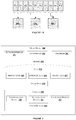
- the media device 100 allocate first packets P1 and P2 to the first network interface 101 1 , subsequent 3 packets, P3, P4 and P5 to the second network interface 101 2 and packets P6, P7, P8, P9 and P10 to the third network interface 101 3 . Further, the allocated packets are requested over respective network interfaces 101, i.e., the packets P1 and P2 are requested over the first network interface 101 1 . Likewise, the packets P3-P5 are requested over the second network interface 101 2 and the packets P6-P10 are requested over the third network interface 101 3 .
- the first network interface 101 1 may be allocated 1 st packet to (N-X) TH packet, where X is an integer.
- the second network 101 2 may be allocated (N-X+1) TH packet to (N-Y) TH packet, where Y is an integer for Y ⁇ X.
- N th network interface 101 N may be allocated (N-Z+1) TH packet to N TH packet, where Z is an integer in a series X, Y, ⁇ Z, for Z ⁇ Y.
- the multimedia data is divided into the packets based on the time frame of the multimedia data. For example, consider a multimedia data of a total time frame of 120 seconds (s). Here, let each time frame be 1s. Thus, there are 120 time frames. Let the time frames 1s-30s correspond to P1, time frames 30s-40s correspond to P2. Likewise, each packet P N represents a range of time frames K-120s, where K represents a time frame between 1s and 120s.
- the network interfaces 101 may include, but is not limited to a cellular network, Wireless fidelity (Wi-Fi), and Bluetooth tethering.
- the media device 100 may include but is not limited to a Personal Digital Assistant (PDA), laptop, cellular phone, tablet and any other computing device comprising a plurality of network interfaces 101.
- PDA Personal Digital Assistant
- the media device 100 may receive the packets from the media server 104 either through a wired interface or a wireless interface.
- the wired interface may include but is not limited to Ethernet, fibre optics, and twisted pair cables.
- the wireless interface may include but is not limited to laser communication, Infra-Red (IR) communication, and Radio Frequency (RF) communication.
- FIG. 2 illustrates internal architecture of the media device 100 in accordance with some embodiments of the present disclosure.
- the media device 100 may include at least one Central Processing Unit ('CPU_ or 'processor_) 203 and a memory 202 storing instructions executable by the at least one processor 203.
- the processor 203 may comprise at least one data processor for executing program components for executing user or system-generated requests.
- the memory 202 is communicatively coupled to the processor 203.
- the media device 100 further comprises an Input/Output (I/O) interface 201.
- the I/O interface 201 is coupled with the processor 203 through which an input signal or/and an output signal is communicated.
- data 204 may be stored within the memory 202.
- the data 204 may include, for example, request data 205, interface data 206, packet data 207, and other data 208.
- the request data 205 includes, but is not limited to, the format of the multimedia data, the size of the multimedia data, and the time frame of the multimedia data.
- the interface data 206 may include, but is not limited to, the number of network interfaces 101 available in the media device 100, the type of network interfaces 101, and the one or more bandwidth parameters of the network interfaces 101.
- the one or more bandwidth parameters may include, but are not limited to, bandwidth size, bandwidth speed, latency, throughput jitter, and error rate.
- the packet data 207 may include, but is not limited to, the number of data packets the multimedia data is divided into, the time frame corresponding to each data packet, and allocation information of the data packets to the network interfaces 101.
- the data 204 in the memory 202 is processed by modules 209 of the media device 100.
- the term module refers to an application specific integrated circuit (ASIC), an electronic circuit, a field-programmable gate arrays (FPGA), a Programmable System-on-Chip (PSoC), a combinational logic circuit, and/or other suitable components that provide the described functionality.
- ASIC application specific integrated circuit
- FPGA field-programmable gate arrays
- PSoC Programmable System-on-Chip
- the modules 209 when configured with the functionality defined in the present disclosure will result in a novel hardware.
- the modules 209 may include, for example, a communication module 210, an identification module 211, an allocation module 212, and other modules 213. It will be appreciated that such aforementioned modules 209 may be represented as a single module or a combination of different modules.
- the communication module 210 receives a request from a user for streaming a multimedia data on the media device 100. Also, the communication module 210 receives the packets from the media server 104 through the network interfaces 101.
- the identification module 211 receives an indication from the communication module 210 regarding the request from the user. Then, the identification module 211 identifies the network interfaces 101 available in the media device 100. In an embodiment, a network interface 101 may be present in the media device 100, but may not be available for streaming the multimedia data. In such a scenario, the identification module 211 may not identify the network interface 101. The identification module 211 may generate a log for storing the identified network interfaces 101.
- the allocation module 212 receives the request data from the communication module 210, and the interface data 206 from the identification module 211. Further, the allocation module 212 determines the one or more bandwidth parameters of each of the available network interfaces 101. Further, the allocation module 212 allocates packets to each of the network interfaces 101 based on the bandwidth parameters. The allocation information of the packets to each of the network interfaces 101 is stored as the packet data 207 by the allocation module 212. The allocation module 212 provides the packet data 207 to the communication module 210 for requesting the packets over the allocated network interfaces 101.
- the other modules 213 may include, but are not limited to, a buffering module, a media parser module, and a media player module.
- the media parser module provides information about the quality of multimedia data, the size of the multimedia data, and the duration of the multimedia data.
- the buffering module receives the packets from the allocated network interfaces 101. Further, the packets are collated by arranging the headers packets in sequence to form the multimedia data. Then, the buffering module provides the multimedia data to the media player module for streaming.
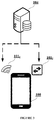
- FIG. 3 shows a block diagram illustrating data flow in accordance with some embodiments of the present disclosure.
- the multimedia data is received by the media device 100 from the media server 104.
- the multimedia data is received as packets from the media server 104.
- the packets are distributed among the network interfaces 101 of the media device 100.
- the network interface 101 1 represents a Wi-Fi network and the network interface 101 2 represents a cellular network.
- the line connecting the media server 104 to the Wi-Fi network 101 1 illustrates that a greater number of packets are received through the Wi-Fi network 101 1 and a lesser number of packets are received through the cellular network 101 2 .
- the packets are received through the e interfaces 101 for streaming the multimedia data.
- Figure 4 shows a flow chart illustrating a method for adaptive streaming of multimedia data, in accordance with some embodiments of the present disclosure.
- the method 400 may comprise one or more steps for adaptive streaming of multimedia data, in accordance with some embodiments of the present disclosure.
- the method 400 may be described in the general context of computer executable instructions.
- computer executable instructions can include routines, programs, objects, components, data structures, procedures, modules, and functions, which perform particular functions or implement particular abstract data types.
- the communication module 210 receives a request from a user for streaming the multimedia data.
- the user may provide information about the multimedia data.
- the information may include, but is not limited to, the name of the multimedia data, the format of the multimedia data, and the quality of the multimedia data.
- the request is transmitted to the media server 104 and in return receives a response from the media server 104.
- the response may indicate, but is not limited to, an acknowledgment for the request made and packet data 207.
- the identification module 211 identifies the network interfaces 101 available in the media device 100.
- the identification module 211 may store identified network interface information in a log.
- the log may include, but is not limited to, the type of the network interfaces 101, the availability of the network interfaces 101, and the bandwidth size of the network interfaces 101.
- the allocation module 212 allocates the packets to the network interfaces 101.
- the allocation module receives the packet data 207 from the communication module 210 and the interface data 206 from the identification module 211.
- the allocation module 212 determines the one or more bandwidth parameters of each of the network interfaces 101. Particularly, the allocation module 212 calculates bandwidth speed of the interfaces 101.
- the third interface 101 3 has more bandwidth speed compared to the first interface 101 1 and the second interface 101 2 .
- a greater number of the packets are allocated to the third interface 101 3 .
- the second interface 101 2 has more bandwidth speed compared to the first interface 101 1 .
- the second interface 101 2 is allocated a greater number of packets than are allocated to the first interface 101 1 .
- the packets may be allocated as shown in Figure 1B .
- packet P1 and packet P2 may be allocated to the first interface 101 1 .
- packet P3, packet P4 and packet P5 may be allocated to the second interface 101 2 .
- packet P6, packet P7, packet P8, packet P9 and packet P10 may be allocated to the third interface 101 3 .
- the communication module 210 requests the packets over the allocated network interfaces 101. Further, the communication module 210 provides the packets to the media buffer 102. The media buffer 102 collates the packets by arranging the header of the packets in a sequence to form the multimedia data. Then, the multimedia data is provided to the media player 103 for streaming.
- the multimedia data can be divided into the packets based on data segments. For example, consider multimedia data of 1 MB (1000 KB). 1MB of the data can be divided into 3 packets. First packet may represent 600 KB of the multimedia data, a second packet may represent 300 KB from remaining 400 KB and a third packet may represent 100 KB.
- the interfaces 101 are monitored by the media device 100 at predefined intervals of time.
- FIG. 5 illustrates a block diagram of an exemplary computer system 500 for implementing embodiments consistent with the present disclosure.
- the computer system 500 is used to implement the method for adaptive streaming of multimedia data.
- the computer system 500 may comprise a central processing unit ("CPU_ or 'processor_) 402.
- the processor 502 may comprise at least one data processor for executing program components for dynamic resource allocation at run time.
- the processor 502 may include specialized processing units such as integrated system (bus) controllers, memory management control units, floating point units, graphics processing units, digital signal processing units, etc.
- the processor 502 may be disposed in communication with one or more input/output (I/O) devices (not shown) via I/O interface 501.
- the I/O interface 501 may employ communication protocols/methods such as, without limitation, audio, analog, digital, RCA, stereo, IEEE-1394, serial bus, universal serial bus (USB), infrared, PS/2, BNC, coaxial, component, composite, digital visual interface (DVI), high-definition multimedia interface (HDMI), RF antennas, S-Video, VGA, IEEE 802.n /b/g/n/x, Bluetooth, cellular (e.g., code-division multiple access (CDMA), high-speed packet access (HSPA+), global system for mobile communications (GSM), long-term evolution (LTE), WiMax, or the like), etc.
- CDMA code-division multiple access
- HSPA+ high-speed packet access
- GSM global system for mobile communications
- LTE long-term evolution
- WiMax wireless wide area network
- the computer system 500 may communicate with one or more I/O devices.
- the input device 510 may be an antenna, keyboard, mouse, joystick, (infrared) remote control, camera, card reader, fax machine, dongle, biometric reader, microphone, touch screen, touchpad, trackball, stylus, scanner, storage device, transceiver, video device/source, etc.
- the output device 511 may be a printer, fax machine, video display (e.g., cathode ray tube (CRT), liquid crystal display (LCD), light-emitting diode (LED), plasma, Plasma display panel (PDP), Organic light-emitting diode display (OLED) or the like), audio speaker, etc.
- CTR cathode ray tube
- LCD liquid crystal display
- LED light-emitting diode
- PDP Plasma display panel
- OLED Organic light-emitting diode display
- the computer system 500 is connected to the service operator through a communication network 509.
- the processor 502 may be disposed in communication with the communication network 509 via a network interface 503.
- the network interface 503 may communicate with the communication network 509.
- the network interface 503 may employ connection protocols including, without limitation, direct connect, Ethernet (e.g., twisted pair 10/100/1000 Base T), transmission control protocol/Internet protocol (TCP/IP), token ring, IEEE 802.11a/b/g/n/x, etc.
- the communication network 509 may include, without limitation, a direct interconnection, e-commerce network, a peer to peer (P2P) network, local area network (LAN), wide area network (WAN), wireless network (e.g., using Wireless Application Protocol), the Internet, Wi-Fi, etc.
- P2P peer to peer
- LAN local area network
- WAN wide area network
- wireless network e.g., using Wireless Application Protocol
- the Internet e.g., Wi-Fi, etc.
- the processor 502 may be disposed in communication with a memory 505 (e.g., RAM, ROM, etc. not shown in Figure 5 ) via a storage interface 504.
- the storage interface 504 may connect to memory 505 including, without limitation, memory drives, removable disc drives, etc., employing connection protocols such as serial advanced technology attachment (SATA), Integrated Drive Electronics (IDE), IEEE-1394, Universal Serial Bus (USB), fibre channel, Small Computer Systems Interface (SCSI), etc.
- the memory drives may further include a drum, magnetic disc drive, magneto-optical drive, optical drive, Redundant Array of Independent Discs (RAID), solid-state memory devices, solid-state drives, etc.
- the memory 505 may store a collection of program or database components, including, without limitation, user interface 506, an operating system 507, web server 508 etc.
- computer system 500 may store user/application data 506, such as the data, variables, records, etc. as described in this disclosure.
- databases may be implemented as fault-tolerant, relational, scalable, secure databases such as Oracle or Sybase.
- the operating system 507 may facilitate resource management and operation of the computer system 500.
- Examples of operating systems include, without limitation, Apple Macintosh OS X, Unix, Unix-like system distributions (e.g., Berkeley Software Distribution (BSD), FreeBSD, NetBSD, OpenBSD, etc.), Linux distributions (e.g., Red Hat, Ubuntu, Kubuntu, etc.), IBM OS/2, Microsoft Windows (XP, Vista/7/8, 10 etc.), Apple iOS, Google Android, Blackberry OS, or the like.
- the computer system 500 may implement a web browser 508 stored program component.
- the web browser 508 may be a hypertext viewing application, such as Microsoft Internet Explorer, Google Chrome, Mozilla Firefox, Apple Safari, etc. Secure web browsing may be provided using Secure Hypertext Transport Protocol (HTTPS), Secure Sockets Layer (SSL), Transport Layer Security (TLS), etc. Web browsers 508 may utilize facilities such as AJAX, DHTML, Adobe Flash, JavaScript, Java, Application Programming Interfaces (APIs), etc.
- the computer system 500 may implement a mail server stored program component.
- the mail server may be an Internet mail server such as Microsoft Exchange, or the like.
- the mail server may utilize facilities such as ASP, ActiveX, ANSI C++/C#, Microsoft.NET, CGI scripts, Java, JavaScript, PERL, PHP, Python, WebObjects, etc.
- the mail server may utilize communication protocols such as Internet Message Access Protocol (IMAP), Messaging Application Programming Interface (MAPI), Microsoft Exchange, Post Office Protocol (POP), Simple Mail Transfer Protocol (SMTP), or the like.
- IMAP Internet Message Access Protocol
- MAPI Messaging Application Programming Interface
- PMP Post Office Protocol
- SMTP Simple Mail Transfer Protocol
- the computer system 500 may implement a mail client stored program component.
- the mail client may be a mail viewing application, such as Apple Mail, Microsoft Entourage, Microsoft Outlook, Mozilla Thunderbird, etc.
- the media server 512 is connected to the communication network 509.
- the media server 512 transmits the multimedia data to the media device 100 for adaptive streaming.
- the present disclosure presents a method and a device for adaptive streaming of the multimedia data.
- the method employed in the present disclosure provides the multimedia data to the user with desired quality.
- the user need not compromise quality of the multimedia data streamed on the media device.
- the present disclosure discloses a method for receiving multimedia data over multiple network interfaces, thus reducing bandwidth congestion in one network bandwidth.
Landscapes
- Engineering & Computer Science (AREA)
- Computer Networks & Wireless Communication (AREA)
- Signal Processing (AREA)
- Multimedia (AREA)
- Environmental & Geological Engineering (AREA)
- Quality & Reliability (AREA)
- Two-Way Televisions, Distribution Of Moving Picture Or The Like (AREA)
Abstract
Description
- The present disclosure relates to streaming multimedia data. Particularly but not exclusively, the present invention relates to a method and a device for streaming multimedia data over multiple network interfaces.
- Streaming is a process of delivering media to an end user in a sequence. Live streaming is a process of streaming media in real-time by collecting media files from a provider. Media may be audio files or video files. Live video streaming is very popular as various media devices support downloading the media files in real-time. A video can be streamed in many qualities, for example, 144p, 240p, 360p, 480p, 720p, 1080p, etc. Here, video streaming of qualities 144p, 240p, 360p and 480p provide low picture quality and require less Internet bandwidth and low data rate for downloading the media files. Video streaming of qualities 720p, 1080p and higher resolution video streaming provide high picture quality and require high bandwidth and high data rate for downloading the media files.
- In a scenario, where a user may require high quality of video streaming but has access to a poor Internet connection, traditional systems automatically decrease quality of video streaming and provide a quality of video streaming such that streaming is not interrupted. Here, video quality is compromised. Thus, the user may not get the desired quality of video streaming.
- Developments are made in video streaming systems for providing the user with high quality video streaming without interruption. Conventional systems use multiple network interfaces for downloading media files for providing high quality video streaming. Here, multiple network interface may be cellular network, Wireless Fidelity (Wi-Fi) network and Bluetooth tethering. The conventional systems download the media files on each of the multiple interfaces. The media files are divided into packets. Here, the packets are received from at least one network interface from the multiple interfaces. However, a packet is received from each of the network interfaces, thus causing repetition of the packets. Also, additional memory may be required to store the packets. Thus, the conventional systems may not be feasible for applications having memory constraints. Also, device transmitting the packets and device receiving the packets may consume more power for transmitting and receiving the same packets respectively.
- The information disclosed in this background of the disclosure section is only for enhancement of understanding of the general background of the invention and should not be taken as an acknowledgement or any form of suggestion that this information forms the prior art already known to a person skilled in the art.
- In one embodiment, the present disclosure provides a method for adaptive streaming of multimedia data. The method comprises receiving, by a media device, a request for streaming a multimedia data, identifying network interfaces available in the media device, allocating data packets to the network interfaces based on one or more bandwidth parameters of the network interfaces, and requesting the data packets of the multimedia data over the allocated interfaces, for adaptively streaming the multimedia data on the media device.
- In one embodiment, the present disclosure provides a device for adaptive streaming of multimedia data. The device comprises a processor and a memory communicatively connected to the processor. The processor is configured to receive a request for streaming a multimedia data, identify network interfaces available in the media device, allocate data packets to the network interfaces based on one or more bandwidth parameters of the network interfaces, and request the data packets of the multimedia data over the allocated interfaces, for adaptively streaming the multimedia data on the media device.
- In an embodiment, the present disclosure relates to a non-transitory computer readable medium including instructions stored thereon that when processed by at least one processor cause a device to perform operations comprising, receiving a request for streaming a multimedia data, wherein the multimedia data is divided into a plurality of data packets, identifying network interfaces available in the media device, allocating data packets from the plurality of data packets to the network interfaces based on one or more bandwidth parameters of the network interfaces, and requesting the data packets of the multimedia data over the allocated interfaces, for adaptively streaming the multimedia data on the media device.
- The foregoing summary is illustrative only and is not intended to be in any way limiting. In addition to the illustrative aspects, embodiments, and features described above, further aspects, embodiments, and features will become apparent by reference to the drawings and the following detailed description.
- The novel features and characteristic of the disclosure are set forth in the appended claims. The disclosure itself, however, as well as a preferred mode of use, further objectives and advantages thereof, will best be understood by reference to the following detailed description of an illustrative embodiment when read in conjunction with the accompanying figures. One or more embodiments are now described, by way of example only, with reference to the accompanying figures wherein like reference numerals represent like elements and in which:
-
Figure 1A shows an exemplary block diagram of a media device for adaptive streaming of multimedia data from a media server, in accordance with some embodiments of the present disclosure; -
Figure 1B shows an example of packet allocation by a media device for adaptive streaming of multimedia data, in accordance with some embodiments of the present disclosure; -
Figure 2 shows internal architecture of a media device for adaptive streaming of multimedia data, in accordance with some embodiments of the present disclosure; -
Figure 3 shows a block diagram illustrating data flow for adaptive streaming of multimedia data, in accordance with some embodiments of the present disclosure; -
Figure 4 shows an exemplary flow chart illustrating method steps for adaptive streaming of multimedia data, in accordance with some embodiments of the present disclosure; and -
Figure 5 shows a general-purpose computer system for adaptive streaming of multimedia data in accordance with some embodiments of the present disclosure. - It should be appreciated by those skilled in the art that any block diagrams herein represent conceptual views of illustrative systems embodying the principles of the present subject matter. Similarly, it will be appreciated that any flow charts, flow diagrams, state transition diagrams, pseudo code, and the like represent various processes which may be substantially represented in computer readable medium and executed by a computer or processor, whether or not such computer or processor is explicitly shown.
- While the disclosure is susceptible to various modifications and alternative forms, specific embodiment thereof has been shown by way of example in the drawings and will be described in detail below. It should be understood, however that it is not intended to limit the disclosure to the particular forms disclosed, but on the contrary, the disclosure is to cover all modifications, equivalents, and alternative falling within the scope of the disclosure.
- Embodiments of the present disclosure relate to a method and a device for adaptive streaming of multimedia data. The device receives a request for downloading multimedia data. The device identifies network interfaces available for downloading the multimedia data. Further, the device calculates bandwidth size and speed of each of the interfaces and allocates specific packets of the multimedia to each of the interfaces. Furthermore, the device requests the specific packets over the interfaces. Thus, the device helps in downloading all the packets of desired quality.
-
Figure 1A shows an exemplary block diagram of amedia device 100 for adaptive streaming of multimedia data.Figure 1A shows themedia device 100 comprising anetwork interface 1011, anetwork interface 1012, ǔ anetwork interface 101N, amedia buffer 102, and amedia player 103. Themedia device 100 is connected to amedia server 104. Thenetwork interface 1011, anetwork interface 1012, ǔ anetwork interface 101N can be collectively represented as one ormore network interfaces 101 in the present disclosure. Further, themedia device 100 is connected to themedia server 104. Themedia server 104 transmits the multimedia data as packets to themedia device 100. Themedia device 100 requests themedia server 104 for the packets through theinterfaces 101. The packets received from themedia server 104 are collected in themedia buffer 102 of themedia device 100. In an embodiment, themedia buffer 102 collates the packets in sequence. Further, the sequenced packets are provided to themedia player 103 for streaming the multimedia data. - In an embodiment, let us consider multimedia data divided into 10 packets. Further let us consider that the
media device 100 comprises three network interfaces 101. Themedia device 100 determines one or more bandwidth parameters of each of the one ormore interfaces 101. In this illustration, themedia device 100 calculates bandwidth size and bandwidth speed of each of the threenetwork interfaces 101 and allocates specific packets from the packets to each of the three network interfaces 101. The allocation of the packets is illustrated inFigure 2 . Considering the 10 packets in a sequence as shown inFigure 2 , let themedia device 100 allocate first packets P1 and P2 to thefirst network interface 1011, subsequent 3 packets, P3, P4 and P5 to thesecond network interface 1012 and packets P6, P7, P8, P9 and P10 to thethird network interface 1013. Further, the allocated packets are requested overrespective network interfaces 101, i.e., the packets P1 and P2 are requested over thefirst network interface 1011. Likewise, the packets P3-P5 are requested over thesecond network interface 1012 and the packets P6-P10 are requested over thethird network interface 1013. In general, if N is the total number of packets, then thefirst network interface 1011 may be allocated 1st packet to (N-X)TH packet, where X is an integer. Similarly, thesecond network 1012 may be allocated (N-X+1)TH packet to (N-Y)TH packet, where Y is an integer for Y<X. Likewise, for Nth network interface 101N may be allocated (N-Z+1)TH packet to NTH packet, where Z is an integer in a series X, Y, ǔ Z, for Z<Y. - In an embodiment, the multimedia data is divided into the packets based on the time frame of the multimedia data. For example, consider a multimedia data of a total time frame of 120 seconds (s). Here, let each time frame be 1s. Thus, there are 120 time frames. Let the time frames 1s-30s correspond to P1, time frames 30s-40s correspond to P2. Likewise, each packet PN represents a range of time frames K-120s, where K represents a time frame between 1s and 120s.
- In an embodiment, the network interfaces 101 may include, but is not limited to a cellular network, Wireless fidelity (Wi-Fi), and Bluetooth tethering. In an embodiment, the
media device 100 may include but is not limited to a Personal Digital Assistant (PDA), laptop, cellular phone, tablet and any other computing device comprising a plurality of network interfaces 101. - In an embodiment, the
media device 100 may receive the packets from themedia server 104 either through a wired interface or a wireless interface. In one embodiment, the wired interface may include but is not limited to Ethernet, fibre optics, and twisted pair cables. In one embodiment, the wireless interface may include but is not limited to laser communication, Infra-Red (IR) communication, and Radio Frequency (RF) communication. -
Figure 2 illustrates internal architecture of themedia device 100 in accordance with some embodiments of the present disclosure. Themedia device 100 may include at least one Central Processing Unit ('CPU_ or 'processor_) 203 and amemory 202 storing instructions executable by the at least oneprocessor 203. Theprocessor 203 may comprise at least one data processor for executing program components for executing user or system-generated requests. Thememory 202 is communicatively coupled to theprocessor 203. Themedia device 100 further comprises an Input/Output (I/O)interface 201. The I/O interface 201 is coupled with theprocessor 203 through which an input signal or/and an output signal is communicated. - In an embodiment,
data 204 may be stored within thememory 202. Thedata 204 may include, for example,request data 205,interface data 206,packet data 207, andother data 208. - In one implementation, the
request data 205 includes, but is not limited to, the format of the multimedia data, the size of the multimedia data, and the time frame of the multimedia data. - In one implementation, the
interface data 206 may include, but is not limited to, the number ofnetwork interfaces 101 available in themedia device 100, the type ofnetwork interfaces 101, and the one or more bandwidth parameters of the network interfaces 101. Here, the one or more bandwidth parameters may include, but are not limited to, bandwidth size, bandwidth speed, latency, throughput jitter, and error rate. - In an embodiment, the
packet data 207 may include, but is not limited to, the number of data packets the multimedia data is divided into, the time frame corresponding to each data packet, and allocation information of the data packets to the network interfaces 101. - In an embodiment, the
data 204 in thememory 202 is processed bymodules 209 of themedia device 100. As used herein, the term module refers to an application specific integrated circuit (ASIC), an electronic circuit, a field-programmable gate arrays (FPGA), a Programmable System-on-Chip (PSoC), a combinational logic circuit, and/or other suitable components that provide the described functionality. Themodules 209 when configured with the functionality defined in the present disclosure will result in a novel hardware. - In one implementation, the
modules 209 may include, for example, acommunication module 210, an identification module 211, anallocation module 212, andother modules 213. It will be appreciated that suchaforementioned modules 209 may be represented as a single module or a combination of different modules. - In an embodiment, the
communication module 210 receives a request from a user for streaming a multimedia data on themedia device 100. Also, thecommunication module 210 receives the packets from themedia server 104 through the network interfaces 101. - In an embodiment, the identification module 211 receives an indication from the
communication module 210 regarding the request from the user. Then, the identification module 211 identifies the network interfaces 101 available in themedia device 100. In an embodiment, anetwork interface 101 may be present in themedia device 100, but may not be available for streaming the multimedia data. In such a scenario, the identification module 211 may not identify thenetwork interface 101. The identification module 211 may generate a log for storing the identified network interfaces 101. - The
allocation module 212 receives the request data from thecommunication module 210, and theinterface data 206 from the identification module 211. Further, theallocation module 212 determines the one or more bandwidth parameters of each of the available network interfaces 101. Further, theallocation module 212 allocates packets to each of the network interfaces 101 based on the bandwidth parameters. The allocation information of the packets to each of the network interfaces 101 is stored as thepacket data 207 by theallocation module 212. Theallocation module 212 provides thepacket data 207 to thecommunication module 210 for requesting the packets over the allocated network interfaces 101. - In an embodiment, the
other modules 213 may include, but are not limited to, a buffering module, a media parser module, and a media player module. The media parser module provides information about the quality of multimedia data, the size of the multimedia data, and the duration of the multimedia data. In an embodiment, the buffering module receives the packets from the allocated network interfaces 101. Further, the packets are collated by arranging the headers packets in sequence to form the multimedia data. Then, the buffering module provides the multimedia data to the media player module for streaming. -
Figure 3 shows a block diagram illustrating data flow in accordance with some embodiments of the present disclosure. As shown in theFigure 3 , the multimedia data is received by themedia device 100 from themedia server 104. Here, the multimedia data is received as packets from themedia server 104. Further, the packets are distributed among the network interfaces 101 of themedia device 100. Thenetwork interface 1011 represents a Wi-Fi network and thenetwork interface 1012 represents a cellular network. Considering that the Wi-Fi network 1011 has more bandwidth speed compared to thecellular network 1012, the line connecting themedia server 104 to the Wi-Fi network 1011 illustrates that a greater number of packets are received through the Wi-Fi network 1011 and a lesser number of packets are received through thecellular network 1012. Thus, the packets are received through the e interfaces 101 for streaming the multimedia data. -
Figure 4 shows a flow chart illustrating a method for adaptive streaming of multimedia data, in accordance with some embodiments of the present disclosure. - As illustrated in
Figure 4 , themethod 400 may comprise one or more steps for adaptive streaming of multimedia data, in accordance with some embodiments of the present disclosure. Themethod 400 may be described in the general context of computer executable instructions. Generally, computer executable instructions can include routines, programs, objects, components, data structures, procedures, modules, and functions, which perform particular functions or implement particular abstract data types. - The order in which the
method 400 is described is not intended to be construed as a limitation, and any number of the described method blocks can be combined in any order to implement the method. Additionally, individual blocks may be deleted from the methods without departing from the scope of the subject matter described herein. Furthermore, the method can be implemented in any suitable hardware, software, firmware, or combination thereof. - At
step 401, thecommunication module 210 receives a request from a user for streaming the multimedia data. Here, the user may provide information about the multimedia data. The information may include, but is not limited to, the name of the multimedia data, the format of the multimedia data, and the quality of the multimedia data. The request is transmitted to themedia server 104 and in return receives a response from themedia server 104. The response may indicate, but is not limited to, an acknowledgment for the request made andpacket data 207. - At
step 402, the identification module 211 identifies the network interfaces 101 available in themedia device 100. The identification module 211 may store identified network interface information in a log. The log may include, but is not limited to, the type of the network interfaces 101, the availability of the network interfaces 101, and the bandwidth size of the network interfaces 101. - At
step 403, theallocation module 212 allocates the packets to the network interfaces 101. The allocation module receives thepacket data 207 from thecommunication module 210 and theinterface data 206 from the identification module 211. Theallocation module 212 determines the one or more bandwidth parameters of each of the network interfaces 101. Particularly, theallocation module 212 calculates bandwidth speed of theinterfaces 101. In a non-limiting embodiment, the bandwidth speed is determined by receiving a sample data from themedia server 104 on each of the one or more network interfaces 101. Further, time taken by the sample data to reach themedia device 100 is determined. Then, the speed is calculated as shown below:
- In
Equation 1 the amount of sample data is measured in bytes and the time is measured in seconds. Further, the bandwidth speed is measured in bits per second (bps). For illustration, let us consider 1Mbyte of sample data is requested from themedia server 104. Let the time taken by the sample data to reach themedia device 100 be 3s. The bandwidth speed is calculated as:
- The bandwidth speed is calculated for each of the one or
more interfaces 101 usingEquation 1. For illustration, let us consider threenetwork interfaces 101, namelyafirst interface 1011, asecond interface 1012 and athird interface 1013. Let the bandwidth speed of thefirst interface 1011, thesecond interface 1012, and thethird interface 1013 be 0.8Mbps, 1Mbps and 3Mbps respectively. Further, the bandwidth speed required for receiving the multimedia data on the network interfaces 101 is determined as given below:
- The
Equation 2 provides bandwidth speed of each of theinterfaces 101 for receiving the multimedia data. From the above illustration, let the total bandwidth speed required for receiving the multimedia data be 3.5 Mbps. The summation of calculated speed of thefirst interface 1011, thesecond interface 1012, and thethird interface 1013 is 0.8 Mbps + 1 Mbps + 3 Mbps = 4.8 Mbps. The bandwidth speed for thefirst interface 1011,second interface 1012, and thethird interface 1013 for receiving the multimedia data is calculated as follows:


- From the above calculation, it evident that the
third interface 1013 has more bandwidth speed compared to thefirst interface 1011 and thesecond interface 1012. Thus, a greater number of the packets are allocated to thethird interface 1013. Likewise, thesecond interface 1012 has more bandwidth speed compared to thefirst interface 1011. Thus, thesecond interface 1012 is allocated a greater number of packets than are allocated to thefirst interface 1011. In an embodiment, the packets may be allocated as shown inFigure 1B . For example, packet P1 and packet P2 may be allocated to thefirst interface 1011. Similarly, packet P3, packet P4 and packet P5 may be allocated to thesecond interface 1012. Similarly, packet P6, packet P7, packet P8, packet P9 and packet P10 may be allocated to thethird interface 1013. - At
step 404, thecommunication module 210 requests the packets over the allocated network interfaces 101. Further, thecommunication module 210 provides the packets to themedia buffer 102. Themedia buffer 102 collates the packets by arranging the header of the packets in a sequence to form the multimedia data. Then, the multimedia data is provided to themedia player 103 for streaming. - In an embodiment, the multimedia data can be divided into the packets based on data segments. For example, consider multimedia data of 1 MB (1000 KB). 1MB of the data can be divided into 3 packets. First packet may represent 600 KB of the multimedia data, a second packet may represent 300 KB from remaining 400 KB and a third packet may represent 100 KB.
- In an embodiment, the
interfaces 101 are monitored by themedia device 100 at predefined intervals of time. -
Figure 5 illustrates a block diagram of anexemplary computer system 500 for implementing embodiments consistent with the present disclosure. In an embodiment, thecomputer system 500 is used to implement the method for adaptive streaming of multimedia data. Thecomputer system 500 may comprise a central processing unit ("CPU_ or 'processor_) 402. Theprocessor 502 may comprise at least one data processor for executing program components for dynamic resource allocation at run time. Theprocessor 502 may include specialized processing units such as integrated system (bus) controllers, memory management control units, floating point units, graphics processing units, digital signal processing units, etc. - The
processor 502 may be disposed in communication with one or more input/output (I/O) devices (not shown) via I/O interface 501. The I/O interface 501 may employ communication protocols/methods such as, without limitation, audio, analog, digital, RCA, stereo, IEEE-1394, serial bus, universal serial bus (USB), infrared, PS/2, BNC, coaxial, component, composite, digital visual interface (DVI), high-definition multimedia interface (HDMI), RF antennas, S-Video, VGA, IEEE 802.n /b/g/n/x, Bluetooth, cellular (e.g., code-division multiple access (CDMA), high-speed packet access (HSPA+), global system for mobile communications (GSM), long-term evolution (LTE), WiMax, or the like), etc. - Using the I/
O interface 501, thecomputer system 500 may communicate with one or more I/O devices. For example, theinput device 510 may be an antenna, keyboard, mouse, joystick, (infrared) remote control, camera, card reader, fax machine, dongle, biometric reader, microphone, touch screen, touchpad, trackball, stylus, scanner, storage device, transceiver, video device/source, etc. Theoutput device 511 may be a printer, fax machine, video display (e.g., cathode ray tube (CRT), liquid crystal display (LCD), light-emitting diode (LED), plasma, Plasma display panel (PDP), Organic light-emitting diode display (OLED) or the like), audio speaker, etc. - In some embodiments, the
computer system 500 is connected to the service operator through acommunication network 509. Theprocessor 502 may be disposed in communication with thecommunication network 509 via anetwork interface 503. Thenetwork interface 503 may communicate with thecommunication network 509. Thenetwork interface 503 may employ connection protocols including, without limitation, direct connect, Ethernet (e.g., twisted pair 10/100/1000 Base T), transmission control protocol/Internet protocol (TCP/IP), token ring, IEEE 802.11a/b/g/n/x, etc. Thecommunication network 509 may include, without limitation, a direct interconnection, e-commerce network, a peer to peer (P2P) network, local area network (LAN), wide area network (WAN), wireless network (e.g., using Wireless Application Protocol), the Internet, Wi-Fi, etc. Using thenetwork interface 503 and thecommunication network 509, thecomputer system 400 may communicate with the one or more service operators. - In some embodiments, the
processor 502 may be disposed in communication with a memory 505 (e.g., RAM, ROM, etc. not shown inFigure 5 ) via astorage interface 504. Thestorage interface 504 may connect tomemory 505 including, without limitation, memory drives, removable disc drives, etc., employing connection protocols such as serial advanced technology attachment (SATA), Integrated Drive Electronics (IDE), IEEE-1394, Universal Serial Bus (USB), fibre channel, Small Computer Systems Interface (SCSI), etc. The memory drives may further include a drum, magnetic disc drive, magneto-optical drive, optical drive, Redundant Array of Independent Discs (RAID), solid-state memory devices, solid-state drives, etc. - The
memory 505 may store a collection of program or database components, including, without limitation, user interface 506, anoperating system 507,web server 508 etc. In some embodiments,computer system 500 may store user/application data 506, such as the data, variables, records, etc. as described in this disclosure. Such databases may be implemented as fault-tolerant, relational, scalable, secure databases such as Oracle or Sybase. - The
operating system 507 may facilitate resource management and operation of thecomputer system 500. Examples of operating systems include, without limitation, Apple Macintosh OS X, Unix, Unix-like system distributions (e.g., Berkeley Software Distribution (BSD), FreeBSD, NetBSD, OpenBSD, etc.), Linux distributions (e.g., Red Hat, Ubuntu, Kubuntu, etc.), IBM OS/2, Microsoft Windows (XP, Vista/7/8, 10 etc.), Apple iOS, Google Android, Blackberry OS, or the like. - In some embodiments, the
computer system 500 may implement aweb browser 508 stored program component. Theweb browser 508 may be a hypertext viewing application, such as Microsoft Internet Explorer, Google Chrome, Mozilla Firefox, Apple Safari, etc. Secure web browsing may be provided using Secure Hypertext Transport Protocol (HTTPS), Secure Sockets Layer (SSL), Transport Layer Security (TLS), etc.Web browsers 508 may utilize facilities such as AJAX, DHTML, Adobe Flash, JavaScript, Java, Application Programming Interfaces (APIs), etc. In some embodiments, thecomputer system 500 may implement a mail server stored program component. The mail server may be an Internet mail server such as Microsoft Exchange, or the like. The mail server may utilize facilities such as ASP, ActiveX, ANSI C++/C#, Microsoft.NET, CGI scripts, Java, JavaScript, PERL, PHP, Python, WebObjects, etc. The mail server may utilize communication protocols such as Internet Message Access Protocol (IMAP), Messaging Application Programming Interface (MAPI), Microsoft Exchange, Post Office Protocol (POP), Simple Mail Transfer Protocol (SMTP), or the like. In some embodiments, thecomputer system 500 may implement a mail client stored program component. The mail client may be a mail viewing application, such as Apple Mail, Microsoft Entourage, Microsoft Outlook, Mozilla Thunderbird, etc. - In an embodiment, the
media server 512 is connected to thecommunication network 509. Themedia server 512 transmits the multimedia data to themedia device 100 for adaptive streaming. - A description of an embodiment with several components in communication with each other does not imply that all such components are required. On the contrary a variety of optional components are described to illustrate the wide variety of possible embodiments of the invention.
- When a single device or article is described herein, it will be readily apparent that more than one device/article (whether or not they cooperate) may be used in place of a single device/article. Similarly, where more than one device or article is described herein (whether or not they cooperate), it will be readily apparent that a single device/article may be used in place of the more than one device or article or a different number of devices/articles may be used instead of the shown number of devices or programs. The functionality and/or the features of a device may be alternatively embodied by one or more other devices which are not explicitly described as having such functionality/features. Thus, other embodiments of the invention need not include the device itself.
- The illustrated operations of
Figure 4 show certain events occurring in a certain order. In alternative embodiments, certain operations may be performed in a different order, modified or removed. Moreover, steps may be added to the above described logic and still conform to the described embodiments. Further, operations described herein may occur sequentially or certain operations may be processed in parallel. Yet further, operations may be performed by a single processing unit or by distributed processing units. - In an embodiment, the present disclosure presents a method and a device for adaptive streaming of the multimedia data. The method employed in the present disclosure provides the multimedia data to the user with desired quality. Thus, the user need not compromise quality of the multimedia data streamed on the media device.
- In an embodiment, the present disclosure discloses a method for receiving multimedia data over multiple network interfaces, thus reducing bandwidth congestion in one network bandwidth.
- Finally, the language used in the specification has been principally selected for readability and instructional purposes. The scope of the invention is to be limited only by the claims. Accordingly, the disclosure of the embodiments of the invention is intended to be illustrative, but not limiting, of the scope of the invention, which is set forth in the following claims.
- While various aspects and embodiments have been disclosed herein, other aspects and embodiments will be apparent to those skilled in the art. The various aspects and embodiments disclosed herein are for purposes of illustration and are not intended to be limiting, with the true scope being indicated by the following claims.
Claims (8)
- A method for adaptive streaming of multimedia data, the method comprising:receiving, by a media device, a request for streaming a multimedia data, wherein the multimedia data is divided into a plurality of data packets;identifying, by the media device, network interfaces available in the media device;allocating, by the media device, data packets from the plurality of data packets, to the e network interfaces, based on one or more bandwidth parameters of the network interfaces; andrequesting, by the media device, the data packets of the multimedia data over the allocated interfaces, for adaptively streaming the multimedia data on the media device.
- The method of claim 1, wherein the plurality of data packets is divided based on time frame of the multimedia data.
- The method of claim 1 or 2, wherein the one or more bandwidth parameters comprises at least one of bandwidth size, bandwidth speed, latency, throughput jitter and error rate.
- The method of claim 1, 2 or 3, wherein the one or more bandwidth parameters of the network interfaces are monitored at predefined intervals of time.
- The method of any preceding claim, further comprising reconstructing the requested data packets for streaming on the media device.
- The method of any preceding claim, wherein the packets are requested from a media server associated with the media device.
- A media device for adaptive streaming of multimedia data, comprising:a processor; anda memory, communicatively coupled with the processor, which stores processor executable instructions, which, on execution causes the processor to perform the method of any preceding claim.
- A non-transitory computer readable medium including instructions stored thereon that when processed by at least one processor cause a device to perform operations comprising the method of any of claims 1 - 6.
Applications Claiming Priority (1)
| Application Number | Priority Date | Filing Date | Title |
|---|---|---|---|
| IN201741003391 | 2017-01-30 |
Publications (2)
| Publication Number | Publication Date |
|---|---|
| EP3355504A1 true EP3355504A1 (en) | 2018-08-01 |
| EP3355504B1 EP3355504B1 (en) | 2022-06-08 |
Family
ID=58489495
Family Applications (1)
| Application Number | Title | Priority Date | Filing Date |
|---|---|---|---|
| EP17163335.7A Active EP3355504B1 (en) | 2017-01-30 | 2017-03-28 | Method and device for adaptive streaming of multimedia data |
Country Status (2)
| Country | Link |
|---|---|
| US (1) | US10693928B2 (en) |
| EP (1) | EP3355504B1 (en) |
Citations (3)
| Publication number | Priority date | Publication date | Assignee | Title |
|---|---|---|---|---|
| WO2009005162A2 (en) * | 2007-06-29 | 2009-01-08 | Kabushiki Kaisha Toshiba | Video streaming over multiple interfaces |
| WO2012037970A1 (en) * | 2010-09-21 | 2012-03-29 | Nokia Siemens Networks Oy | Method and network devices for splitting of a data stream |
| US20140029527A1 (en) * | 2012-07-27 | 2014-01-30 | Fujitsu Limited | Base station apparatus and wireless terminal apparatus |
Family Cites Families (8)
| Publication number | Priority date | Publication date | Assignee | Title |
|---|---|---|---|---|
| US7415528B2 (en) * | 2003-12-27 | 2008-08-19 | Electronics And Telecommunications Research Institute | Apparatus and method for transmitting hierarchically multimedia data TS to prevent jitter of timing information and for recovering the multimedia data TS |
| US8325601B2 (en) | 2009-05-08 | 2012-12-04 | Canon Kabushiki Kaisha | Reliable network streaming of a single data stream over multiple physical interfaces |
| JP5673538B2 (en) * | 2009-08-10 | 2015-02-18 | 日本電気株式会社 | Distribution system |
| US20150006621A1 (en) * | 2013-07-01 | 2015-01-01 | Futurewei Technologies, Inc. | Adaptive Video Streaming for Information Centric Networks |
| KR102024315B1 (en) * | 2013-12-11 | 2019-09-23 | 한국전자통신연구원 | Mobile telecommunication terminal having multiple communication interfaces and its cooperative data communication method |
| US9635077B2 (en) | 2014-03-14 | 2017-04-25 | Adobe Systems Incorporated | Low latency live video streaming |
| KR101873969B1 (en) | 2014-06-30 | 2018-07-04 | 에코스타 테크놀로지스 엘엘씨 | Adaptive data segment delivery arbitration for bandwidth optimization |
| KR102209292B1 (en) * | 2015-11-04 | 2021-01-29 | 삼성전자 주식회사 | Method and apparatus for providing data in multimedia system |
-
2017
- 2017-03-13 US US15/456,901 patent/US10693928B2/en active Active
- 2017-03-28 EP EP17163335.7A patent/EP3355504B1/en active Active
Patent Citations (3)
| Publication number | Priority date | Publication date | Assignee | Title |
|---|---|---|---|---|
| WO2009005162A2 (en) * | 2007-06-29 | 2009-01-08 | Kabushiki Kaisha Toshiba | Video streaming over multiple interfaces |
| WO2012037970A1 (en) * | 2010-09-21 | 2012-03-29 | Nokia Siemens Networks Oy | Method and network devices for splitting of a data stream |
| US20140029527A1 (en) * | 2012-07-27 | 2014-01-30 | Fujitsu Limited | Base station apparatus and wireless terminal apparatus |
Also Published As
| Publication number | Publication date |
|---|---|
| US20180219927A1 (en) | 2018-08-02 |
| EP3355504B1 (en) | 2022-06-08 |
| US10693928B2 (en) | 2020-06-23 |
Similar Documents
| Publication | Publication Date | Title |
|---|---|---|
| EP3462684B1 (en) | Method and system for adaptive and context-aware service function chaining in communication networks | |
| EP3293928B1 (en) | System and method for transmitting data over a communication network | |
| US10491758B2 (en) | Method and system for optimizing image data for data transmission | |
| US10182098B2 (en) | Method and system for proactively selecting a content distribution network (CDN) for delivering content | |
| CN106713156B (en) | System and method for adjusting per-hop behavior of one or more expedited forwarding packets | |
| US10764366B2 (en) | System and method for storing data in data storage unit of virtual storage area network | |
| US10848462B2 (en) | Method and system for managing policies in a network security system | |
| EP3627726A1 (en) | Method and system for adaptive light fidelity (li-fi) communication | |
| US20250393048A1 (en) | Method and system for allocating pucch resources to user equipments in a communication network | |
| US9609660B2 (en) | System and method for adaptive downlink scheduler for wireless networks | |
| EP3174302B1 (en) | System and method for dynamically optimizing video quality during video transmission | |
| US11997337B2 (en) | Method and system for optimizing video content acquisition and delivery during events | |
| US20170147764A1 (en) | Method and system for predicting consultation duration | |
| EP3355504B1 (en) | Method and device for adaptive streaming of multimedia data | |
| US10182117B2 (en) | Method and system for transmitting data from telemetry devices to eNodeB over wireless communication network | |
| US11064222B1 (en) | System and method for delivering cloud DVR content | |
| KR20260041124A (en) | Optimization of model performance of user devices (UEs) based on collective intelligence at base stations | |
| US20180013482A1 (en) | Method and unit for mapping information bits to polarization angles of a wave | |
| EP3035759B1 (en) | System and method for adaptive downlink scheduling for wireless networks | |
| US10338948B2 (en) | Method and device for managing execution of scripts by a virtual computing unit | |
| US10200730B2 (en) | Method and system for facilitating delivery of recorded data over a network | |
| US12273654B2 (en) | Method of managing media communication in mission critical (MC) system, MC server, and receiver thereof | |
| US9917999B2 (en) | System and method for capturing multi-media of an area of interest using multi-media capturing devices | |
| US20160205433A1 (en) | Method and system for managing tuners of client devices |
Legal Events
| Date | Code | Title | Description |
|---|---|---|---|
| PUAI | Public reference made under article 153(3) epc to a published international application that has entered the european phase |
Free format text: ORIGINAL CODE: 0009012 |
|
| STAA | Information on the status of an ep patent application or granted ep patent |
Free format text: STATUS: THE APPLICATION HAS BEEN PUBLISHED |
|
| AK | Designated contracting states |
Kind code of ref document: A1 Designated state(s): AL AT BE BG CH CY CZ DE DK EE ES FI FR GB GR HR HU IE IS IT LI LT LU LV MC MK MT NL NO PL PT RO RS SE SI SK SM TR |
|
| AX | Request for extension of the european patent |
Extension state: BA ME |
|
| STAA | Information on the status of an ep patent application or granted ep patent |
Free format text: STATUS: REQUEST FOR EXAMINATION WAS MADE |
|
| 17P | Request for examination filed |
Effective date: 20190201 |
|
| RBV | Designated contracting states (corrected) |
Designated state(s): AL AT BE BG CH CY CZ DE DK EE ES FI FR GB GR HR HU IE IS IT LI LT LU LV MC MK MT NL NO PL PT RO RS SE SI SK SM TR |
|
| STAA | Information on the status of an ep patent application or granted ep patent |
Free format text: STATUS: EXAMINATION IS IN PROGRESS |
|
| 17Q | First examination report despatched |
Effective date: 20200923 |
|
| GRAP | Despatch of communication of intention to grant a patent |
Free format text: ORIGINAL CODE: EPIDOSNIGR1 |
|
| STAA | Information on the status of an ep patent application or granted ep patent |
Free format text: STATUS: GRANT OF PATENT IS INTENDED |
|
| INTG | Intention to grant announced |
Effective date: 20220103 |
|
| GRAS | Grant fee paid |
Free format text: ORIGINAL CODE: EPIDOSNIGR3 |
|
| GRAA | (expected) grant |
Free format text: ORIGINAL CODE: 0009210 |
|
| STAA | Information on the status of an ep patent application or granted ep patent |
Free format text: STATUS: THE PATENT HAS BEEN GRANTED |
|
| AK | Designated contracting states |
Kind code of ref document: B1 Designated state(s): AL AT BE BG CH CY CZ DE DK EE ES FI FR GB GR HR HU IE IS IT LI LT LU LV MC MK MT NL NO PL PT RO RS SE SI SK SM TR |
|
| REG | Reference to a national code |
Ref country code: AT Ref legal event code: REF Ref document number: 1497650 Country of ref document: AT Kind code of ref document: T Effective date: 20220615 Ref country code: CH Ref legal event code: EP |
|
| REG | Reference to a national code |
Ref country code: DE Ref legal event code: R096 Ref document number: 602017058216 Country of ref document: DE |
|
| REG | Reference to a national code |
Ref country code: IE Ref legal event code: FG4D |
|
| REG | Reference to a national code |
Ref country code: LT Ref legal event code: MG9D |
|
| REG | Reference to a national code |
Ref country code: NL Ref legal event code: MP Effective date: 20220608 |
|
| PG25 | Lapsed in a contracting state [announced via postgrant information from national office to epo] |
Ref country code: SE Free format text: LAPSE BECAUSE OF FAILURE TO SUBMIT A TRANSLATION OF THE DESCRIPTION OR TO PAY THE FEE WITHIN THE PRESCRIBED TIME-LIMIT Effective date: 20220608 Ref country code: NO Free format text: LAPSE BECAUSE OF FAILURE TO SUBMIT A TRANSLATION OF THE DESCRIPTION OR TO PAY THE FEE WITHIN THE PRESCRIBED TIME-LIMIT Effective date: 20220908 Ref country code: LT Free format text: LAPSE BECAUSE OF FAILURE TO SUBMIT A TRANSLATION OF THE DESCRIPTION OR TO PAY THE FEE WITHIN THE PRESCRIBED TIME-LIMIT Effective date: 20220608 Ref country code: HR Free format text: LAPSE BECAUSE OF FAILURE TO SUBMIT A TRANSLATION OF THE DESCRIPTION OR TO PAY THE FEE WITHIN THE PRESCRIBED TIME-LIMIT Effective date: 20220608 Ref country code: GR Free format text: LAPSE BECAUSE OF FAILURE TO SUBMIT A TRANSLATION OF THE DESCRIPTION OR TO PAY THE FEE WITHIN THE PRESCRIBED TIME-LIMIT Effective date: 20220909 Ref country code: FI Free format text: LAPSE BECAUSE OF FAILURE TO SUBMIT A TRANSLATION OF THE DESCRIPTION OR TO PAY THE FEE WITHIN THE PRESCRIBED TIME-LIMIT Effective date: 20220608 Ref country code: ES Free format text: LAPSE BECAUSE OF FAILURE TO SUBMIT A TRANSLATION OF THE DESCRIPTION OR TO PAY THE FEE WITHIN THE PRESCRIBED TIME-LIMIT Effective date: 20220608 Ref country code: BG Free format text: LAPSE BECAUSE OF FAILURE TO SUBMIT A TRANSLATION OF THE DESCRIPTION OR TO PAY THE FEE WITHIN THE PRESCRIBED TIME-LIMIT Effective date: 20220908 |
|
| REG | Reference to a national code |
Ref country code: AT Ref legal event code: MK05 Ref document number: 1497650 Country of ref document: AT Kind code of ref document: T Effective date: 20220608 |
|
| PG25 | Lapsed in a contracting state [announced via postgrant information from national office to epo] |
Ref country code: RS Free format text: LAPSE BECAUSE OF FAILURE TO SUBMIT A TRANSLATION OF THE DESCRIPTION OR TO PAY THE FEE WITHIN THE PRESCRIBED TIME-LIMIT Effective date: 20220608 Ref country code: LV Free format text: LAPSE BECAUSE OF FAILURE TO SUBMIT A TRANSLATION OF THE DESCRIPTION OR TO PAY THE FEE WITHIN THE PRESCRIBED TIME-LIMIT Effective date: 20220608 |
|
| PG25 | Lapsed in a contracting state [announced via postgrant information from national office to epo] |
Ref country code: NL Free format text: LAPSE BECAUSE OF FAILURE TO SUBMIT A TRANSLATION OF THE DESCRIPTION OR TO PAY THE FEE WITHIN THE PRESCRIBED TIME-LIMIT Effective date: 20220608 |
|
| PG25 | Lapsed in a contracting state [announced via postgrant information from national office to epo] |
Ref country code: SM Free format text: LAPSE BECAUSE OF FAILURE TO SUBMIT A TRANSLATION OF THE DESCRIPTION OR TO PAY THE FEE WITHIN THE PRESCRIBED TIME-LIMIT Effective date: 20220608 Ref country code: SK Free format text: LAPSE BECAUSE OF FAILURE TO SUBMIT A TRANSLATION OF THE DESCRIPTION OR TO PAY THE FEE WITHIN THE PRESCRIBED TIME-LIMIT Effective date: 20220608 Ref country code: RO Free format text: LAPSE BECAUSE OF FAILURE TO SUBMIT A TRANSLATION OF THE DESCRIPTION OR TO PAY THE FEE WITHIN THE PRESCRIBED TIME-LIMIT Effective date: 20220608 Ref country code: PT Free format text: LAPSE BECAUSE OF FAILURE TO SUBMIT A TRANSLATION OF THE DESCRIPTION OR TO PAY THE FEE WITHIN THE PRESCRIBED TIME-LIMIT Effective date: 20221010 Ref country code: EE Free format text: LAPSE BECAUSE OF FAILURE TO SUBMIT A TRANSLATION OF THE DESCRIPTION OR TO PAY THE FEE WITHIN THE PRESCRIBED TIME-LIMIT Effective date: 20220608 Ref country code: CZ Free format text: LAPSE BECAUSE OF FAILURE TO SUBMIT A TRANSLATION OF THE DESCRIPTION OR TO PAY THE FEE WITHIN THE PRESCRIBED TIME-LIMIT Effective date: 20220608 Ref country code: AT Free format text: LAPSE BECAUSE OF FAILURE TO SUBMIT A TRANSLATION OF THE DESCRIPTION OR TO PAY THE FEE WITHIN THE PRESCRIBED TIME-LIMIT Effective date: 20220608 |
|
| PG25 | Lapsed in a contracting state [announced via postgrant information from national office to epo] |
Ref country code: PL Free format text: LAPSE BECAUSE OF FAILURE TO SUBMIT A TRANSLATION OF THE DESCRIPTION OR TO PAY THE FEE WITHIN THE PRESCRIBED TIME-LIMIT Effective date: 20220608 Ref country code: IS Free format text: LAPSE BECAUSE OF FAILURE TO SUBMIT A TRANSLATION OF THE DESCRIPTION OR TO PAY THE FEE WITHIN THE PRESCRIBED TIME-LIMIT Effective date: 20221008 |
|
| REG | Reference to a national code |
Ref country code: DE Ref legal event code: R097 Ref document number: 602017058216 Country of ref document: DE |
|
| PG25 | Lapsed in a contracting state [announced via postgrant information from national office to epo] |
Ref country code: AL Free format text: LAPSE BECAUSE OF FAILURE TO SUBMIT A TRANSLATION OF THE DESCRIPTION OR TO PAY THE FEE WITHIN THE PRESCRIBED TIME-LIMIT Effective date: 20220608 |
|
| PLBE | No opposition filed within time limit |
Free format text: ORIGINAL CODE: 0009261 |
|
| STAA | Information on the status of an ep patent application or granted ep patent |
Free format text: STATUS: NO OPPOSITION FILED WITHIN TIME LIMIT |
|
| PG25 | Lapsed in a contracting state [announced via postgrant information from national office to epo] |
Ref country code: DK Free format text: LAPSE BECAUSE OF FAILURE TO SUBMIT A TRANSLATION OF THE DESCRIPTION OR TO PAY THE FEE WITHIN THE PRESCRIBED TIME-LIMIT Effective date: 20220608 |
|
| 26N | No opposition filed |
Effective date: 20230310 |
|
| PG25 | Lapsed in a contracting state [announced via postgrant information from national office to epo] |
Ref country code: SI Free format text: LAPSE BECAUSE OF FAILURE TO SUBMIT A TRANSLATION OF THE DESCRIPTION OR TO PAY THE FEE WITHIN THE PRESCRIBED TIME-LIMIT Effective date: 20220608 |
|
| P01 | Opt-out of the competence of the unified patent court (upc) registered |
Effective date: 20230605 |
|
| PG25 | Lapsed in a contracting state [announced via postgrant information from national office to epo] |
Ref country code: MC Free format text: LAPSE BECAUSE OF FAILURE TO SUBMIT A TRANSLATION OF THE DESCRIPTION OR TO PAY THE FEE WITHIN THE PRESCRIBED TIME-LIMIT Effective date: 20220608 |
|
| REG | Reference to a national code |
Ref country code: CH Ref legal event code: PL |
|
| REG | Reference to a national code |
Ref country code: BE Ref legal event code: MM Effective date: 20230331 |
|
| PG25 | Lapsed in a contracting state [announced via postgrant information from national office to epo] |
Ref country code: LU Free format text: LAPSE BECAUSE OF NON-PAYMENT OF DUE FEES Effective date: 20230328 |
|
| REG | Reference to a national code |
Ref country code: IE Ref legal event code: MM4A |
|
| PG25 | Lapsed in a contracting state [announced via postgrant information from national office to epo] |
Ref country code: LI Free format text: LAPSE BECAUSE OF NON-PAYMENT OF DUE FEES Effective date: 20230331 Ref country code: IT Free format text: LAPSE BECAUSE OF FAILURE TO SUBMIT A TRANSLATION OF THE DESCRIPTION OR TO PAY THE FEE WITHIN THE PRESCRIBED TIME-LIMIT Effective date: 20220608 Ref country code: IE Free format text: LAPSE BECAUSE OF NON-PAYMENT OF DUE FEES Effective date: 20230328 Ref country code: CH Free format text: LAPSE BECAUSE OF NON-PAYMENT OF DUE FEES Effective date: 20230331 |
|
| PG25 | Lapsed in a contracting state [announced via postgrant information from national office to epo] |
Ref country code: BE Free format text: LAPSE BECAUSE OF NON-PAYMENT OF DUE FEES Effective date: 20230331 |
|
| PG25 | Lapsed in a contracting state [announced via postgrant information from national office to epo] |
Ref country code: BG Free format text: LAPSE BECAUSE OF FAILURE TO SUBMIT A TRANSLATION OF THE DESCRIPTION OR TO PAY THE FEE WITHIN THE PRESCRIBED TIME-LIMIT Effective date: 20220608 |
|
| PG25 | Lapsed in a contracting state [announced via postgrant information from national office to epo] |
Ref country code: BG Free format text: LAPSE BECAUSE OF FAILURE TO SUBMIT A TRANSLATION OF THE DESCRIPTION OR TO PAY THE FEE WITHIN THE PRESCRIBED TIME-LIMIT Effective date: 20220608 |
|
| PG25 | Lapsed in a contracting state [announced via postgrant information from national office to epo] |
Ref country code: CY Free format text: LAPSE BECAUSE OF FAILURE TO SUBMIT A TRANSLATION OF THE DESCRIPTION OR TO PAY THE FEE WITHIN THE PRESCRIBED TIME-LIMIT; INVALID AB INITIO Effective date: 20170328 |
|
| PG25 | Lapsed in a contracting state [announced via postgrant information from national office to epo] |
Ref country code: HU Free format text: LAPSE BECAUSE OF FAILURE TO SUBMIT A TRANSLATION OF THE DESCRIPTION OR TO PAY THE FEE WITHIN THE PRESCRIBED TIME-LIMIT; INVALID AB INITIO Effective date: 20170328 |
|
| PG25 | Lapsed in a contracting state [announced via postgrant information from national office to epo] |
Ref country code: TR Free format text: LAPSE BECAUSE OF FAILURE TO SUBMIT A TRANSLATION OF THE DESCRIPTION OR TO PAY THE FEE WITHIN THE PRESCRIBED TIME-LIMIT Effective date: 20220608 |
|
| PGFP | Annual fee paid to national office [announced via postgrant information from national office to epo] |
Ref country code: GB Payment date: 20260209 Year of fee payment: 10 |
|
| PGFP | Annual fee paid to national office [announced via postgrant information from national office to epo] |
Ref country code: DE Payment date: 20260204 Year of fee payment: 10 |
|
| PGFP | Annual fee paid to national office [announced via postgrant information from national office to epo] |
Ref country code: FR Payment date: 20260209 Year of fee payment: 10 |