EP3355441A1 - Electric motor and tangential type permanent magnet rotor thereof - Google Patents
Electric motor and tangential type permanent magnet rotor thereof Download PDFInfo
- Publication number
- EP3355441A1 EP3355441A1 EP16847836.0A EP16847836A EP3355441A1 EP 3355441 A1 EP3355441 A1 EP 3355441A1 EP 16847836 A EP16847836 A EP 16847836A EP 3355441 A1 EP3355441 A1 EP 3355441A1
- Authority
- EP
- European Patent Office
- Prior art keywords
- permanent magnet
- rotor
- tangential type
- magnet rotor
- iron core
- Prior art date
- Legal status (The legal status is an assumption and is not a legal conclusion. Google has not performed a legal analysis and makes no representation as to the accuracy of the status listed.)
- Granted
Links
Images

Classifications
-
- H—ELECTRICITY
- H02—GENERATION; CONVERSION OR DISTRIBUTION OF ELECTRIC POWER
- H02K—DYNAMO-ELECTRIC MACHINES
- H02K1/00—Details of the magnetic circuit
- H02K1/06—Details of the magnetic circuit characterised by the shape, form or construction
- H02K1/22—Rotating parts of the magnetic circuit
- H02K1/27—Rotor cores with permanent magnets
- H02K1/2706—Inner rotors
- H02K1/272—Inner rotors the magnetisation axis of the magnets being perpendicular to the rotor axis
- H02K1/274—Inner rotors the magnetisation axis of the magnets being perpendicular to the rotor axis the rotor consisting of two or more circumferentially positioned magnets
- H02K1/2753—Inner rotors the magnetisation axis of the magnets being perpendicular to the rotor axis the rotor consisting of two or more circumferentially positioned magnets the rotor consisting of magnets or groups of magnets arranged with alternating polarity
- H02K1/276—Magnets embedded in the magnetic core, e.g. interior permanent magnets [IPM]
- H02K1/2766—Magnets embedded in the magnetic core, e.g. interior permanent magnets [IPM] having a flux concentration effect
- H02K1/2773—Magnets embedded in the magnetic core, e.g. interior permanent magnets [IPM] having a flux concentration effect consisting of tangentially magnetized radial magnets
-
- H—ELECTRICITY
- H01—ELECTRIC ELEMENTS
- H01F—MAGNETS; INDUCTANCES; TRANSFORMERS; SELECTION OF MATERIALS FOR THEIR MAGNETIC PROPERTIES
- H01F13/00—Apparatus or processes for magnetising or demagnetising
- H01F13/003—Methods and devices for magnetising permanent magnets
-
- H—ELECTRICITY
- H02—GENERATION; CONVERSION OR DISTRIBUTION OF ELECTRIC POWER
- H02K—DYNAMO-ELECTRIC MACHINES
- H02K1/00—Details of the magnetic circuit
- H02K1/06—Details of the magnetic circuit characterised by the shape, form or construction
- H02K1/22—Rotating parts of the magnetic circuit
- H02K1/27—Rotor cores with permanent magnets
-
- H—ELECTRICITY
- H02—GENERATION; CONVERSION OR DISTRIBUTION OF ELECTRIC POWER
- H02K—DYNAMO-ELECTRIC MACHINES
- H02K2213/00—Specific aspects, not otherwise provided for and not covered by codes H02K2201/00 - H02K2211/00
- H02K2213/03—Machines characterised by numerical values, ranges, mathematical expressions or similar information
Definitions
- the present invention relates to a technical field of electric motor devices, and more particularly, to an electric motor and a tangential type permanent magnet rotor thereof.
- An electric motor of a permanent magnet tangential-magnetization structure can generate a higher air gap flux density than a permanent magnet radial-magnetization electric motor due to its magnetism gathering effect.
- the electric motor has a relatively large torque/current ratio and torque/volume ratio and is increasingly applied to an occasion such as a servo system, electric traction, office automation and a household electrical appliance.
- a tangential permanent magnet electric motor due to a magnetic circuit structure in which single permanent magnets are in parallel connection, operating points of the permanent magnets are lower than a radial magnetic electric motor. Moreover, most permanent magnets are of a rectangular shape, and widths thereof along a radial direction of a rotor are almost the same. However, the intensities of a demagnetized field on different parts of the permanent magnets are different and this is the case for the operating points on different parts of the same permanent magnet. Hence, the overall demagnetization resistance of the electric motor is reduced. Particularly, the closer the permanent magnets are to an outer side of the rotor, the stronger the intensities of the demagnetized field are borne, such that an efficiency of the electric motor is reduced.
- the present invention is intended to provide a tangential type permanent magnet rotor, so as to reduce a local demagnetization of permanent magnets and ensure an efficiency of an electric motor.
- the present invention further provides an electric motor having the above tangential type permanent magnet rotor.
- the present invention provides a tangential type permanent magnet rotor, which comprises a rotor iron core and permanent magnets provided on the rotor iron core, a width of one side, close to an outer edge of the rotor iron core, of each of the permanent magnets is H2; and a width of one side, close to a center of the rotor iron core, of each of the permanent magnets is H1, wherein H2>H1.
- a maximum included angle of a magnetic conductive passage between adjacent two permanent magnets is A2, and a minimum included angle of each of the permanent magnets is A1, A2 ⁇ A1,the A1 is an included angle of connecting lines that are respectively between two ends of a surface at one side, close to the outer edge of the rotor iron core, of each of the permanent magnets and the center of the rotor iron core; the A2 is an included angle of connecting lines that are respectively between two ends of a surface at one side, close to the outer edge of the rotor iron core, of the magnetic conductive passage between the adjacent two of the permanent magnets and the center of the rotor iron core.
- a cross section, perpendicular to an axial line of the tangential type permanent magnet rotor, of each of the permanent magnets is of an isosceles trapezoid; and an upper bottom of the isosceles trapezoid is provided at a side close to the center of the rotor iron core.
- a cross section, perpendicular to an axial line of the tangential type permanent magnet rotor, of each of the permanent magnets is of a non-isosceles trapezoid, an upper bottom of the non-isosceles trapezoid is provided at a side close to the center of the rotor iron core, and a waist of the non-isosceles trapezoid comprises a first waist provided at a front side of a rotation direction of the tangential type permanent magnet rotor and a second waist provided at a rear side of the rotation direction of the tangential type permanent magnet rotor; a length of the first waist is greater than that of the second waist.
- the rotor iron core is further provided with an inside magnetism isolating structure provided between sides, close to the center of the rotor iron core, of the adjacent two of the permanent magnets, a cross section, perpendicular to an axial line of the tangential type permanent magnet rotor, of the inside magnetism isolating structure is of a triangular or trapezoidal structure; a small end of the inside magnetism isolating structure is towards the center of the rotor iron core.
- a middle line of each of the permanent magnets is provided at a front side of a rotation direction of the tangential type permanent magnet rotor, the tangential type permanent magnet rotor is provided on a diameter line of the corresponding each of permanent magnets, the diameter line is a straight line where a diameter of the rotor iron core perpendicular to a side, close to the center of the rotor iron core, of each of the permanent magnets is located.
- the present invention further provides an electric motor, comprising a tangential type permanent magnet rotor; the tangential type permanent magnet rotor is the tangential type permanent magnet rotor described above.
- the tangential type permanent magnet rotor provided by the present invention enables the width H2 of a permanent magnet part close to the outer edge of the rotor iron core to be larger, and enables the width H1 of a permanent magnet part close to the center of the rotor iron core to be smaller, so that operating points at two sides (the side close to the center of the rotor iron core and the side close to the outer edge of the rotor iron core) of each of the permanent magnets and operating points of a permanent magnet with equal widths in the related art have relatively high consistency, thus reducing the effect of local demagnetization of the permanent magnets, and ensuring the efficiency of the electric motor.
- the present invention further provides the electric motor having the above tangential type permanent magnet rotor.
- the tangential type permanent magnet rotor has the above technical effects, so the electric motor having the tangential type permanent magnet rotor also should have the same technical effects, which will not be described in detail here.
- the core of the present invention is to provide a tangential type permanent magnet rotor so as to reduce a local demagnetization effect of permanent magnets and ensuring an efficiency of an electric motor.
- the present invention further provides an electric motor having the above tangential type permanent magnet rotor.
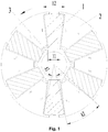
- Fig. 1 is a first structural schematic diagram of a tangential type permanent magnet rotor provided by the present invention.
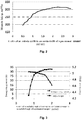
- Fig. 2 is a systematic diagram illustrating a relationship between a width ratio of a permanent magnet and a magnetic linkage of a tangential type permanent magnet rotor provided by the present invention.
- the tangential type permanent magnet rotor comprises a rotor iron core 2 and permanent magnets 1 provided on the rotor iron core 2, wherein an even number of the permanent magnets 1 are provided and the permanent magnets 1 are evenly provided on the rotor iron core 2; homopolarities of adjacent two permanent magnets 1 are opposite.
- the tangential type permanent magnet rotor provided by the embodiment of the present invention enables the width H2 of a permanent magnet part close to the outer edge of the rotor iron core 2 to be larger, and enables the width H1 of a permanent magnet part close to the center of the rotor iron core 2 to be smaller, so that operating points at two sides (a side close to the center of the rotor iron core 2 and a side close to the outer edge of the rotor iron core 2) of each of the permanent magnets 1 and operating points of a permanent magnet with equal widths in the prior art have relatively high consistency, thus reducing an effect of local demagnetization of the permanent magnets, and ensuring an efficiency of the electric motor.
- a reversed magnetic field of a stator externally added on the rotor is more applied to positions, close to the inside of the rotor, of the permanent magnets, such that the permanent magnets at positions with relatively high operating points bear a large intensity of the demagnetizing field, and those at positions with relatively low operating points bear a small intensity of the demagnetizing field.
- the magnetic field of each of the whole permanent magnets is more evenly, and the air gap magnetic flux density generated by the permanent magnets of the electric motor has a lower harmonic content.
- the higher H2/H1 ratio is not the better.
- a stator magnetic linkage is basically no longer increased and thus the stator magnetic flux is no longer increased. Therefore, in order to ensure a utilization rate of the permanent magnets 1 and reduce the cost, in each of the permanent magnets 1, 2.2 ⁇ H2/H1.
- the stator magnetic linkage is increased more obviously, such that the electric motor has a higher efficiency.
- a rotor magnetic flux also enters the stator via a silicon steel sheet magnetic conductive passage in the middle of two adjacent permanent magnets.
- the maximum included angle of the magnetic conductive passage between adjacent two permanent magnets 1 is A2, and the minimum included angle for the permanent magnets 1 is A1, A2 ⁇ A1.
- the A1 is an included angle of connecting lines that are respectively between two ends of a surface at one side, close to the outer edge of the rotor iron core 2, of each of the permanent magnets 1 and the center of the rotor iron core 2;
- the A2 is an included angle of connecting lines that are respectively between two ends of a surface at one side, close to the outer edge of the rotor iron core 2, of the magnetic conductive passage between the adjacent two of the permanent magnets 1 and the center of the rotor iron core 2.
- the magnetic conductive passage between the adjacent two permanent magnets 1 are not obviously saturated under the heavy load, such that an output torque of the electric motor is not reduced.
- the larger magnetic conductive passages between the permanent magnets are not the better.
- the A2 are increased, it is easy to cause that a demagnetization resistance of the electric motor is reduced.
- the A2 is smaller than or equal to 1.6A1.
- a cross section, perpendicular to an axial line of the tangential type permanent magnet rotor, of each of the permanent magnets 1 is of a non-isosceles trapezoid, an upper bottom of the non-isosceles trapezoid is provided at a side close to the center of the rotor iron core 2, and a waist of the non-isosceles trapezoid comprises a first waist provided at a front side of a rotation direction of the tangential type permanent magnet rotor and a second waist provided at a rear side of the rotation direction of the tangential type permanent magnet rotor; a length of the first waist is greater than that of the second waist.
- the rotor iron core 2 is provided with an outside magnetism isolating bridge provided at one side, close to the outer edge of the rotor iron core 2, of each of the permanent magnets 1.
- Each of the outside magnetism isolating bridges comprises a first outside magnetism isolating bridge provided at the front side of the rotation direction of the tangential type permanent magnet rotor, and a second outside magnetism isolating bridge provided at the rear side of the rotation direction of the tangential type permanent magnet rotor. That is, a sum of the first outside magnetism isolating bridge and the second outside magnetism isolating bridge is smaller than the width H2 of the corresponding each of the permanent magnets 1.
- a thickness B1 of each of the first outside magnetism isolating bridges is greater than a thickness B2 of each of the second outside magnetism isolating bridges, and a length D1 of each of the first outside magnetism isolating bridges is smaller than a length D2 of each of the second outside magnetism isolating bridges.
- the rotor iron core 2 is further provided with an inside magnetism isolating structure provided between certain sides, close to the center of the rotor iron core 2, of the adjacent two of the permanent magnets 1.
- a cross section, perpendicular to an axial line of the tangential type permanent magnet rotor, of the inside magnetism isolating structure is of a triangular or trapezoidal structure; a small end of the inside magnetism isolating structure is towards the center of the rotor iron core 2.
- Two magnetism isolating bridges are provided between the adjacent two permanent magnets 1. To simplify the structure here, the two magnetism isolating bridges are respectively provided in the inside magnetism isolating structure.
- each of the permanent magnets 1 is of a trapezoidal structure
- the two magnetism isolating bridges respectively are two edges of the inside magnetism isolating structure; moreover, an included angle is respectively provided between the two magnetism isolating bridges, such that a cross section, perpendicular to the axial line of the tangential type permanent magnet rotor, of each of the inside magnetism isolating structures is of the triangular or trapezoidal structure; and thus, a silicon steel sheet structure between the two permanent magnets has better structural strength and is not tilted easily, thereby guaranteeing the dimensional stability of permanent magnet grooves for accommodating the permanent magnets 1 in the rotor iron core 2.
- a first inside magnetism isolating bridge is formed between the inside magnetism isolating structure and each of the permanent magnets 1 provided at a front side of the rotation direction of the tangential type permanent magnet rotor;
- a second inside magnetism isolating bridge is formed between the inside magnetism isolating structure and each of the permanent magnets 1 provided at a rear side of the rotation direction of the tangential type permanent magnet rotor;
- a thickness C1 of the first inside magnetism isolating bridge is greater than a thickness C2 of the second inside magnetism isolating bridge.
- a middle line of each of the permanent magnets 1 is provided at a front side of a rotation direction of the tangential type permanent magnet rotor provided on a diameter line of the corresponding permanent magnet 1.
- the diameter line is a straight line where a diameter of the rotor iron core perpendicular to a side, close to the center of the rotor iron core 2, of each of the permanent magnets 1 is located.
- each of the permanent magnets 1 is tilted to the front side of the rotation direction of the rotor, such that the electric motor can generate a larger torque under a same current, a torque pulsation of the electric motor is reduced and an electromagnetic noise of the electric motor is reduced.
- the embodiment of the present invention further provides an electric motor, comprising a tangential type permanent magnet rotor; the tangential type permanent magnet rotor is the tangential type permanent magnet rotor described above.
- the electric motor having the tangential type permanent magnet rotor also should have the same technical effects, which will not be described in detail here.
Landscapes
- Engineering & Computer Science (AREA)
- Power Engineering (AREA)
- Permanent Field Magnets Of Synchronous Machinery (AREA)
Abstract
Description
- This application claims a priority to the Chinese patent application No.
201510622376.0 - The present invention relates to a technical field of electric motor devices, and more particularly, to an electric motor and a tangential type permanent magnet rotor thereof.
- An electric motor of a permanent magnet tangential-magnetization structure can generate a higher air gap flux density than a permanent magnet radial-magnetization electric motor due to its magnetism gathering effect. As a result, the electric motor has a relatively large torque/current ratio and torque/volume ratio and is increasingly applied to an occasion such as a servo system, electric traction, office automation and a household electrical appliance.
- In a tangential permanent magnet electric motor, due to a magnetic circuit structure in which single permanent magnets are in parallel connection, operating points of the permanent magnets are lower than a radial magnetic electric motor. Moreover, most permanent magnets are of a rectangular shape, and widths thereof along a radial direction of a rotor are almost the same. However, the intensities of a demagnetized field on different parts of the permanent magnets are different and this is the case for the operating points on different parts of the same permanent magnet. Hence, the overall demagnetization resistance of the electric motor is reduced. Particularly, the closer the permanent magnets are to an outer side of the rotor, the stronger the intensities of the demagnetized field are borne, such that an efficiency of the electric motor is reduced.
- Therefore, how to reduce the local demagnetization of the permanent magnets and ensure the efficiency of the electric motor is a technical problem to be solved by a person skilled in the art at present.
- The present invention is intended to provide a tangential type permanent magnet rotor, so as to reduce a local demagnetization of permanent magnets and ensure an efficiency of an electric motor. The present invention further provides an electric motor having the above tangential type permanent magnet rotor.
- To solve the above technical problem, the present invention provides a tangential type permanent magnet rotor, which comprises a rotor iron core and permanent magnets provided on the rotor iron core, a width of one side, close to an outer edge of the rotor iron core, of each of the permanent magnets is H2; and a width of one side, close to a center of the rotor iron core, of each of the permanent magnets is H1, wherein H2>H1.
- Preferably, in the above tangential type permanent magnet rotor, 2.2≥H2/H1≥1.2.
- Preferably, in the above tangential type permanent magnet rotor, a maximum included angle of a magnetic conductive passage between adjacent two permanent magnets is A2, and a minimum included angle of each of the permanent magnets is A1, A2≥A1,the A1 is an included angle of connecting lines that are respectively between two ends of a surface at one side, close to the outer edge of the rotor iron core, of each of the permanent magnets and the center of the rotor iron core; the A2 is an included angle of connecting lines that are respectively between two ends of a surface at one side, close to the outer edge of the rotor iron core, of the magnetic conductive passage between the adjacent two of the permanent magnets and the center of the rotor iron core.
- Preferably, in the above tangential type permanent magnet rotor, A2≤1.6A1.
- Preferably, in the above tangential type permanent magnet rotor, a cross section, perpendicular to an axial line of the tangential type permanent magnet rotor, of each of the permanent magnets is of an isosceles trapezoid; and an upper bottom of the isosceles trapezoid is provided at a side close to the center of the rotor iron core.
- Preferably, in the above tangential type permanent magnet rotor, a cross section, perpendicular to an axial line of the tangential type permanent magnet rotor, of each of the permanent magnets is of a non-isosceles trapezoid, an upper bottom of the non-isosceles trapezoid is provided at a side close to the center of the rotor iron core, and a waist of the non-isosceles trapezoid comprises a first waist provided at a front side of a rotation direction of the tangential type permanent magnet rotor and a second waist provided at a rear side of the rotation direction of the tangential type permanent magnet rotor; a length of the first waist is greater than that of the second waist.
- Preferably, in the above tangential type permanent magnet rotor, the rotor iron core is provided with an outside magnetism isolating bridge provided at one side, close to the outer edge of the rotor iron core, of each of the permanent magnets, the outside magnetism isolating bridge comprises a first outside magnetism isolating bridge provided at a front side of the rotation direction of the tangential type permanent magnet rotor, and a second outside magnetism isolating bridge provided at a rear side of the rotation direction of the tangential type permanent magnet rotor, a thickness B1 of the first outside magnetism isolating bridge is greater than a thickness B2 of the second outside magnetism isolating bridge; a length D1 of the first outside magnetism isolating bridge is smaller than a length D2 of the second outside magnetism isolating bridge.
- Preferably, in the above tangential type permanent magnet rotor, the rotor iron core is further provided with an inside magnetism isolating structure provided between sides, close to the center of the rotor iron core, of the adjacent two of the permanent magnets, a cross section, perpendicular to an axial line of the tangential type permanent magnet rotor, of the inside magnetism isolating structure is of a triangular or trapezoidal structure; a small end of the inside magnetism isolating structure is towards the center of the rotor iron core.
- Preferably, in the above tangential type permanent magnet rotor, a first inside magnetism isolating bridge is formed between the inside magnetism isolating structure and each of the permanent magnets provided at a front side of a rotation direction of the tangential type permanent magnet rotor; a second inside magnetism isolating bridge is formed between the inside magnetism isolating structure and each of the permanent magnets provided at a rear side of the rotation direction of the tangential type permanent magnet rotor, a thickness C1 of the first inside magnetism isolating bridge is greater than a thickness C2 of the second inside magnetism isolating bridge.
- Preferably, in the above tangential type permanent magnet rotor, a middle line of each of the permanent magnets is provided at a front side of a rotation direction of the tangential type permanent magnet rotor, the tangential type permanent magnet rotor is provided on a diameter line of the corresponding each of permanent magnets, the diameter line is a straight line where a diameter of the rotor iron core perpendicular to a side, close to the center of the rotor iron core, of each of the permanent magnets is located.
- The present invention further provides an electric motor, comprising a tangential type permanent magnet rotor; the tangential type permanent magnet rotor is the tangential type permanent magnet rotor described above.
- The tangential type permanent magnet rotor provided by the present invention enables the width H2 of a permanent magnet part close to the outer edge of the rotor iron core to be larger, and enables the width H1 of a permanent magnet part close to the center of the rotor iron core to be smaller, so that operating points at two sides (the side close to the center of the rotor iron core and the side close to the outer edge of the rotor iron core) of each of the permanent magnets and operating points of a permanent magnet with equal widths in the related art have relatively high consistency, thus reducing the effect of local demagnetization of the permanent magnets, and ensuring the efficiency of the electric motor.
- The present invention further provides the electric motor having the above tangential type permanent magnet rotor. The tangential type permanent magnet rotor has the above technical effects, so the electric motor having the tangential type permanent magnet rotor also should have the same technical effects, which will not be described in detail here.
-
-
Fig. 1 is a first structural schematic diagram of a tangential type permanent magnet rotor provided by the present invention. -
Fig. 2 is a systematic diagram illustrating a relationship between a width ratio of a permanent magnet and a magnetic linkage of a tangential type permanent magnet rotor provided by the present invention. -
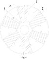
Fig. 3 is a systematic diagram illustrating a relationship among an included angle ratio, a demagnetizing current and an output torque of a tangential type permanent magnet rotor provided by the present invention. -
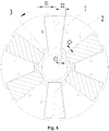
Fig. 4 is a second structural schematic diagram of a tangential type permanent magnet rotor provided by the present invention. -
Fig. 5 is a third structural schematic diagram of a tangential type permanent magnet rotor provided by the present invention. -
Fig. 6 is a fourth structural schematic diagram of a tangential type permanent magnet rotor provided by the present invention. -
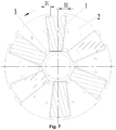
Fig. 7 is a fifth structural schematic diagram of a tangential type permanent magnet rotor provided by the present invention. - The core of the present invention is to provide a tangential type permanent magnet rotor so as to reduce a local demagnetization effect of permanent magnets and ensuring an efficiency of an electric motor. The present invention further provides an electric motor having the above tangential type permanent magnet rotor.
- To make a person skilled in the art better understand the solutions of the present invention, the present invention will be further described in detail with reference to accompanying drawings and specific implementation manners.
- Please referring to
Fig. 1 andFig. 2 ,Fig. 1 is a first structural schematic diagram of a tangential type permanent magnet rotor provided by the present invention.Fig. 2 is a systematic diagram illustrating a relationship between a width ratio of a permanent magnet and a magnetic linkage of a tangential type permanent magnet rotor provided by the present invention. - In this specific implementation manner, the tangential type permanent magnet rotor comprises a
rotor iron core 2 andpermanent magnets 1 provided on therotor iron core 2, wherein an even number of thepermanent magnets 1 are provided and thepermanent magnets 1 are evenly provided on therotor iron core 2; homopolarities of adjacent twopermanent magnets 1 are opposite. - In the embodiment, a width of one side, close to an outer edge of the
rotor iron core 2, of each of thepermanent magnets 1 is H2; and a width of one side, close to a center of therotor iron core 2, of each of thepermanent magnets 1 is H1, wherein H2>H1. - The tangential type permanent magnet rotor provided by the embodiment of the present invention enables the width H2 of a permanent magnet part close to the outer edge of the
rotor iron core 2 to be larger, and enables the width H1 of a permanent magnet part close to the center of therotor iron core 2 to be smaller, so that operating points at two sides (a side close to the center of therotor iron core 2 and a side close to the outer edge of the rotor iron core 2) of each of thepermanent magnets 1 and operating points of a permanent magnet with equal widths in the prior art have relatively high consistency, thus reducing an effect of local demagnetization of the permanent magnets, and ensuring an efficiency of the electric motor. - Further, in the tangential type permanent magnet rotor provided by the embodiment of the present invention, a value range for the width at two sides of each of the
permanent magnets 1 is as follows: 2.2≥H2/H1≥1.2. - The present invention will be described below in conjunction with
Fig. 2 . - It is found in a research that, when the electric motor operates with a load, an operating point, close to an outside of the rotor, of each of the permanent magnets is lower than that of a part close to an inside. The parts that generate a stator flux in the permanent magnets are mainly focused in the outside of the rotor. By setting the widths H2, close to the outside of the rotor, of the permanent magnets to be greater than the widths H1 close to the inside of the rotor, the operating points, close to the outside of the rotor, of the
permanent magnets 1 can be effectively improved. Furthermore, as a thickness of the outside is increased, a reversed magnetic field of a stator externally added on the rotor is more applied to positions, close to the inside of the rotor, of the permanent magnets, such that the permanent magnets at positions with relatively high operating points bear a large intensity of the demagnetizing field, and those at positions with relatively low operating points bear a small intensity of the demagnetizing field. Hence, the magnetic field of each of the whole permanent magnets is more evenly, and the air gap magnetic flux density generated by the permanent magnets of the electric motor has a lower harmonic content. However, the higher H2/H1 ratio is not the better. When the H2/H1>2.2, a stator magnetic linkage is basically no longer increased and thus the stator magnetic flux is no longer increased. Therefore, in order to ensure a utilization rate of thepermanent magnets 1 and reduce the cost, in each of thepermanent magnets 1, 2.2≥H2/H1. - Further, to achieve a better effect, by providing the H2/H1 to be equal to or greater than 1.2, the stator magnetic linkage is increased more obviously, such that the electric motor has a higher efficiency.
- In addition, through finite element simulation, it is found that, a rotor magnetic flux also enters the stator via a silicon steel sheet magnetic conductive passage in the middle of two adjacent permanent magnets. When the electric motor is heavily loaded, it is the most easy to occur magnetic saturation in the silicon steel sheet magnetic conductive passage such that a torque of the electric motor is reduced. The maximum included angle of the magnetic conductive passage between adjacent two
permanent magnets 1 is A2, and the minimum included angle for thepermanent magnets 1 is A1, A2≥A1. As shown inFig. 2 , the A1 is an included angle of connecting lines that are respectively between two ends of a surface at one side, close to the outer edge of therotor iron core 2, of each of thepermanent magnets 1 and the center of therotor iron core 2; the A2 is an included angle of connecting lines that are respectively between two ends of a surface at one side, close to the outer edge of therotor iron core 2, of the magnetic conductive passage between the adjacent two of thepermanent magnets 1 and the center of therotor iron core 2. As shown inFig. 3 , the magnetic conductive passage between the adjacent twopermanent magnets 1 are not obviously saturated under the heavy load, such that an output torque of the electric motor is not reduced. - Further, the larger magnetic conductive passages between the permanent magnets are not the better. While the A2 are increased, it is easy to cause that a demagnetization resistance of the electric motor is reduced. As shown in
Fig. 3 , preferably, the A2 is smaller than or equal to 1.6A1. Hence, in the embodiment, 1≤A2/A1≤1.6. - As shown in
Fig. 1 , in the embodiment, a cross section, perpendicular to an axial line of the tangential type permanent magnet rotor, of each of thepermanent magnets 1 is of an isosceles trapezoid; an upper bottom of the isosceles trapezoid is provided at a side close to the center of therotor iron core 2. Through the above arrangement, each of thepermanent magnets 1 is of a centrosymmetric structure, and a center line of each of thepermanent magnets 1 is a middle line of the isosceles trapezoid. Through the above arrangement, it is convenient to process and assemble thepermanent magnets 1. - As shown in
Fig. 4 , in the embodiment, a cross section, perpendicular to an axial line of the tangential type permanent magnet rotor, of each of thepermanent magnets 1 is of a non-isosceles trapezoid, an upper bottom of the non-isosceles trapezoid is provided at a side close to the center of therotor iron core 2, and a waist of the non-isosceles trapezoid comprises a first waist provided at a front side of a rotation direction of the tangential type permanent magnet rotor and a second waist provided at a rear side of the rotation direction of the tangential type permanent magnet rotor; a length of the first waist is greater than that of the second waist. Through the above arrangement, an area of a surface, positioned at the front side of the rotation direction of the tangential type permanent magnet rotor, of each of thepermanent magnets 1 is greater than that of a surface, positioned at the rear side of the rotation direction of the tangential type permanent magnet rotor, of each of thepermanent magnets 1, so that thepermanent magnets 1 generate a larger stator magnetic flux. - The
rotor iron core 2 is provided with an outside magnetism isolating bridge provided at one side, close to the outer edge of therotor iron core 2, of each of thepermanent magnets 1. Each of the outside magnetism isolating bridges comprises a first outside magnetism isolating bridge provided at the front side of the rotation direction of the tangential type permanent magnet rotor, and a second outside magnetism isolating bridge provided at the rear side of the rotation direction of the tangential type permanent magnet rotor. That is, a sum of the first outside magnetism isolating bridge and the second outside magnetism isolating bridge is smaller than the width H2 of the corresponding each of thepermanent magnets 1. Through the above arrangement, it is ensured that thepermanent magnets 1 are fixed inside therotor iron core 2. And meanwhile, the flux leakage of thepermanent magnets 1 in an outside of the tangential type permanent magnet rotor is reduced. When the electric motor rotates, stresses borne by the first outside magnetism isolating bridges and the second outside magnetism isolating bridges in the outside of the tangential type permanent magnet rotor are not the same. The stress of each of the first outside magnetism isolating bridges at the front side of the rotation direction of the tangential type permanent magnet rotor is greater than that of each of the second outside magnetism isolating bridges at the rear side all the time. Therefore, a thickness B1 of each of the first outside magnetism isolating bridges is greater than a thickness B2 of each of the second outside magnetism isolating bridges, and a length D1 of each of the first outside magnetism isolating bridges is smaller than a length D2 of each of the second outside magnetism isolating bridges. Through the above arrangement, a stress concentration is reduced, and a mechanical strength of the tangential type permanent magnet rotor is enhanced. - Further, as shown in
Fig. 5 andFig. 6 , therotor iron core 2 is further provided with an inside magnetism isolating structure provided between certain sides, close to the center of therotor iron core 2, of the adjacent two of thepermanent magnets 1. A cross section, perpendicular to an axial line of the tangential type permanent magnet rotor, of the inside magnetism isolating structure is of a triangular or trapezoidal structure; a small end of the inside magnetism isolating structure is towards the center of therotor iron core 2. Two magnetism isolating bridges are provided between the adjacent twopermanent magnets 1. To simplify the structure here, the two magnetism isolating bridges are respectively provided in the inside magnetism isolating structure. Because each of thepermanent magnets 1 is of a trapezoidal structure, the two magnetism isolating bridges respectively are two edges of the inside magnetism isolating structure; moreover, an included angle is respectively provided between the two magnetism isolating bridges, such that a cross section, perpendicular to the axial line of the tangential type permanent magnet rotor, of each of the inside magnetism isolating structures is of the triangular or trapezoidal structure; and thus, a silicon steel sheet structure between the two permanent magnets has better structural strength and is not tilted easily, thereby guaranteeing the dimensional stability of permanent magnet grooves for accommodating thepermanent magnets 1 in therotor iron core 2. - Further, a first inside magnetism isolating bridge is formed between the inside magnetism isolating structure and each of the
permanent magnets 1 provided at a front side of the rotation direction of the tangential type permanent magnet rotor; a second inside magnetism isolating bridge is formed between the inside magnetism isolating structure and each of thepermanent magnets 1 provided at a rear side of the rotation direction of the tangential type permanent magnet rotor; a thickness C1 of the first inside magnetism isolating bridge is greater than a thickness C2 of the second inside magnetism isolating bridge. Through the above arrangement, a stress concentration of the first inside magnetism isolating bridge is avoided. - As shown in
Fig. 7 , a middle line of each of thepermanent magnets 1 is provided at a front side of a rotation direction of the tangential type permanent magnet rotor provided on a diameter line of the correspondingpermanent magnet 1. The diameter line is a straight line where a diameter of the rotor iron core perpendicular to a side, close to the center of therotor iron core 2, of each of thepermanent magnets 1 is located. - Through the above arrangement, each of the
permanent magnets 1 is tilted to the front side of the rotation direction of the rotor, such that the electric motor can generate a larger torque under a same current, a torque pulsation of the electric motor is reduced and an electromagnetic noise of the electric motor is reduced. - The embodiment of the present invention further provides an electric motor, comprising a tangential type permanent magnet rotor; the tangential type permanent magnet rotor is the tangential type permanent magnet rotor described above. As the tangential type permanent magnet rotor has the above technical effects, the electric motor having the tangential type permanent magnet rotor also should have the same technical effects, which will not be described in detail here.
- The above describes the tangential type permanent magnet rotor provided by the present disclosure in detail. In the specification, the principle and implementation manners of the present disclosure are described using a specific embodiment, and the description on the above embodiment only is intended to understand the method of the present disclosure and the core concept thereof. It should be noted that, those of ordinary skill in the art further may make various improvements and modifications on the present disclosure without departing from the principle of the present disclosure. The improvements and the modifications should all fall in the protection scope of the appended claims of the present invention.
Claims (11)
- A tangential type permanent magnet rotor, comprising a rotor iron core (2) and permanent magnets (1) provided on the rotor iron core (2), wherein
a width of one side, close to an outer edge of the rotor iron core (2), of each of the permanent magnets (1) is H2; and a width of one side, close to a center of the rotor iron core (2), of each of the permanent magnets (1) is H1, wherein H2>H1. - The tangential type permanent magnet rotor as claimed in claim 1, wherein 2.2≥H2/H1≥1.2.
- The tangential type permanent magnet rotor as claimed in claim 1, wherein a maximum included angle of a magnetic conductive passage between adjacent two permanent magnets (1) is A2, and a minimum included angle of each of the permanent magnets (1) is A1, A2≥A1;
the A1 is an included angle of connecting lines that are respectively between two ends of a surface at one side, close to the outer edge of the rotor iron core (2), of each of the permanent magnets (1) and the center of the rotor iron core (2); the A2 is an included angle of connecting lines that are respectively between two ends of a surface at one side, close to the outer edge of the rotor iron core (2), of the magnetic conductive passage between the adjacent two permanent magnets (1) and the center of the rotor iron core (2). - The tangential type permanent magnet rotor as claimed in claim 3, wherein A2≤1.6A1.
- The tangential type permanent magnet rotor as claimed in claim 1, wherein a cross section, perpendicular to an axial line of the tangential type permanent magnet rotor, of each of the permanent magnets (1) is of an isosceles trapezoid; an upper bottom of the isosceles trapezoid is provided at a side close to the center of the rotor iron core (2).
- The tangential type permanent magnet rotor as claimed in claim 1, wherein a cross section, perpendicular to an axial line of the tangential type permanent magnet rotor, of each of the permanent magnets (1) is of a non-isosceles trapezoid, an upper bottom of the non-isosceles trapezoid is provided at a side close to the center of the rotor iron core (2), and a waist of the non-isosceles trapezoid comprises a first waist provided at a front side of a rotation direction of the tangential type permanent magnet rotor and a second waist provided at a rear side of the rotation direction of the tangential type permanent magnet rotor; a length of the first waist is greater than that of the second waist.
- The tangential type permanent magnet rotor as claimed in claim 1, wherein the rotor iron core (2) is provided with an outside magnetism isolating bridge provided at one side, close to the outer edge of the rotor iron core (2), of each of the permanent magnets (1);
the outside magnetism isolating bridge comprises a first outside magnetism isolating bridge provided at a front side of a rotation direction of the tangential type permanent magnet rotor, and a second outside magnetism isolating bridge provided at a rear side of the rotation direction of the tangential type permanent magnet rotor;
a thickness B1 of the first outside magnetism isolating bridge is greater than a thickness B2 of the second outside magnetism isolating bridge; a length D1 of the first outside magnetism isolating bridge is smaller than a length D2 of the second outside magnetism isolating bridge. - The tangential type permanent magnet rotor as claimed in claim 1, wherein the rotor iron core (2) is further provided with an inside magnetism isolating structure provided between sides, close to the center of the rotor iron core, of the adjacent two of the permanent magnets (1);
a cross section, perpendicular to an axial line of the tangential type permanent magnet rotor, of the inside magnetism isolating structure is of a triangular or trapezoidal structure; a small end of the inside magnetism isolating structure is towards the center of the rotor iron core (2). - The tangential type permanent magnet rotor as claimed in claim 8, wherein a first inside magnetism isolating bridge is formed between the inside magnetism isolating structure and each of the permanent magnets (1) provided at a front side of a rotation direction of the tangential type permanent magnet rotor; a second inside magnetism isolating bridge is formed between the inside magnetism isolating structure and each of the permanent magnets (1) provided at a rear side of the rotation direction of the tangential type permanent magnet rotor;
a thickness C1 of the first inside magnetism isolating bridge is greater than a thickness C2 of the second inside magnetism isolating bridge. - The tangential type permanent magnet rotor as claimed in claim 1, wherein a middle line of each of the permanent magnets (1) is provided at a front side of a rotation direction of the tangential type permanent magnet rotor, the tangential type permanent magnet rotor is provided on a diameter line of the corresponding each of permanent magnets (1);
the diameter line is a straight line where a diameter of the rotor iron core perpendicular to a side, close to the center of the rotor iron core, of each of the permanent magnets (1) is located. - An electrical motor, comprising a tangential type permanent magnet rotor, wherein the tangential type permanent magnet rotor is the tangential type permanent magnet rotor according to any one of claims 1-10.
Applications Claiming Priority (2)
| Application Number | Priority Date | Filing Date | Title |
|---|---|---|---|
| CN201510622376.0A CN106558931B (en) | 2015-09-24 | 2015-09-24 | Motor and tangential permanent magnet rotor thereof |
| PCT/CN2016/084524 WO2017049954A1 (en) | 2015-09-24 | 2016-06-02 | Electric motor and tangential type permanent magnet rotor thereof |
Publications (3)
| Publication Number | Publication Date |
|---|---|
| EP3355441A1 true EP3355441A1 (en) | 2018-08-01 |
| EP3355441A4 EP3355441A4 (en) | 2019-04-17 |
| EP3355441B1 EP3355441B1 (en) | 2022-04-13 |
Family
ID=58385812
Family Applications (1)
| Application Number | Title | Priority Date | Filing Date |
|---|---|---|---|
| EP16847836.0A Active EP3355441B1 (en) | 2015-09-24 | 2016-06-02 | Electric motor and tangential type permanent magnet rotor thereof |
Country Status (5)
| Country | Link |
|---|---|
| US (1) | US10630124B2 (en) |
| EP (1) | EP3355441B1 (en) |
| KR (1) | KR102021710B1 (en) |
| CN (1) | CN106558931B (en) |
| WO (1) | WO2017049954A1 (en) |
Families Citing this family (7)
| Publication number | Priority date | Publication date | Assignee | Title |
|---|---|---|---|---|
| CN112117846A (en) * | 2019-06-19 | 2020-12-22 | 上海海立电器有限公司 | Special-shaped permanent magnet structure of motor rotor and compressor |
| CN110299772B (en) * | 2019-07-26 | 2021-07-20 | 珠海格力节能环保制冷技术研究中心有限公司 | Rotors, Tangential Motors and Compressors |
| CN110474456B (en) * | 2019-08-30 | 2025-06-27 | 珠海格力节能环保制冷技术研究中心有限公司 | Permanent magnet synchronous motor rotor and compressor having the same |
| CN114268181A (en) * | 2021-12-24 | 2022-04-01 | 宁波恒帅股份有限公司 | Permanent magnet motor capable of reducing cogging torque ripple |
| CN115189495A (en) * | 2022-06-17 | 2022-10-14 | 无锡世珂微电机有限公司 | Ferrite permanent magnet motor of automobile air conditioner compressor |
| CN115118042A (en) * | 2022-07-06 | 2022-09-27 | 珠海格力电器股份有限公司 | Rotor core, rotor structure and motor |
| CN119582491B (en) * | 2025-01-17 | 2025-06-06 | 南京师范大学 | A tangentially magnetized segmented permanent magnet low voltage regulation rate generator rotor structure |
Family Cites Families (17)
| Publication number | Priority date | Publication date | Assignee | Title |
|---|---|---|---|---|
| CN101232205A (en) | 2008-01-25 | 2008-07-30 | 东南大学 | Variable flux permanent magnet synchronous motor |
| CN201146439Y (en) * | 2008-01-25 | 2008-11-05 | 东南大学 | Variable flux permanent magnet synchronous motor |
| JP2009268204A (en) * | 2008-04-23 | 2009-11-12 | Toyota Motor Corp | Rotor for ipm motor, and ipm motor |
| CN201270437Y (en) * | 2008-09-22 | 2009-07-08 | 重庆帕特龙智通电子科技有限公司 | Permanent magneto generator rotor |
| JP5521820B2 (en) * | 2009-09-07 | 2014-06-18 | 株式会社安川電機 | Rotating electric machine and manufacturing method thereof |
| WO2012012464A2 (en) | 2010-07-19 | 2012-01-26 | Remy Technologies, Llc | Cooling system and method for an electric machine module |
| CN102306966A (en) * | 2011-09-14 | 2012-01-04 | 天津市松正电动汽车技术股份有限公司 | Permanent magnet motor rotor |
| FR2982093B1 (en) | 2011-10-27 | 2017-11-03 | Valeo Equip Electr Moteur | ROTOR OF ROTATING ELECTRIC MACHINE AND ROTATING ELECTRIC MACHINE COMPRISING A ROTOR |
| CN103107665A (en) * | 2011-11-11 | 2013-05-15 | 德昌电机(深圳)有限公司 | Permanent magnet motor and electric tool and mower utilizing the same |
| CN103166345B (en) * | 2011-12-12 | 2017-12-08 | 德昌电机(深圳)有限公司 | Brushless electric machine and its rotor |
| KR101331654B1 (en) | 2012-04-23 | 2013-11-20 | 삼성전기주식회사 | Rotor Assembly |
| KR20150007371A (en) | 2013-07-10 | 2015-01-21 | 동진모타공업 주식회사 | Rotor of blush less direct current motor |
| CN104600938B (en) | 2013-12-25 | 2016-03-09 | 珠海格力节能环保制冷技术研究中心有限公司 | Magneto |
| CN204068474U (en) * | 2014-09-04 | 2014-12-31 | 珠海格力节能环保制冷技术研究中心有限公司 | Rotor structure and motor |
| CN204376558U (en) | 2015-02-12 | 2015-06-03 | 珠海格力节能环保制冷技术研究中心有限公司 | Rotor core and there is its motor |
| CN204669114U (en) * | 2015-05-29 | 2015-09-23 | 珠海格力节能环保制冷技术研究中心有限公司 | Permanent magnet machine rotor and permagnetic synchronous motor |
| CN205017131U (en) * | 2015-09-24 | 2016-02-03 | 珠海格力节能环保制冷技术研究中心有限公司 | Motor and tangential formula permanent magnet rotor thereof |
-
2015
- 2015-09-24 CN CN201510622376.0A patent/CN106558931B/en active Active
-
2016
- 2016-06-02 WO PCT/CN2016/084524 patent/WO2017049954A1/en not_active Ceased
- 2016-06-02 KR KR1020187009600A patent/KR102021710B1/en active Active
- 2016-06-02 US US15/762,714 patent/US10630124B2/en active Active
- 2016-06-02 EP EP16847836.0A patent/EP3355441B1/en active Active
Also Published As
| Publication number | Publication date |
|---|---|
| EP3355441A4 (en) | 2019-04-17 |
| EP3355441B1 (en) | 2022-04-13 |
| US20180287442A1 (en) | 2018-10-04 |
| WO2017049954A1 (en) | 2017-03-30 |
| KR102021710B1 (en) | 2019-09-16 |
| CN106558931A (en) | 2017-04-05 |
| KR20180044424A (en) | 2018-05-02 |
| US10630124B2 (en) | 2020-04-21 |
| CN106558931B (en) | 2019-12-24 |
Similar Documents
| Publication | Publication Date | Title |
|---|---|---|
| US10630124B2 (en) | Electric motor and tangential type permanent magnet rotor thereof | |
| CN107240975B (en) | Tangential motor, tangential motor rotor and rotor core | |
| CN204928523U (en) | Permanent Magnet Brushless DC Motor | |
| KR101981292B1 (en) | Permanent magnet motor rotor and permanent magnet synchronous motor | |
| EP3534496A1 (en) | Permanent magnet motor | |
| CN107017750B (en) | Motor | |
| CN118367744B (en) | Motor and compressor with same | |
| CN103117611B (en) | A kind of permanent magnet motor | |
| CN205017131U (en) | Motor and tangential formula permanent magnet rotor thereof | |
| CN111864940A (en) | Core structure, rotor assembly, motor and compressor | |
| CN106300729B (en) | Permanent magnet motor rotor and permanent magnet synchronous motor | |
| CN107248793B (en) | Tangential motor, tangential motor rotor and rotor core | |
| JP7304411B2 (en) | Motor rotor structure and permanent magnet motor | |
| CN114709949B (en) | Motor rotor, motor, compressor and air conditioner | |
| WO2015180577A1 (en) | Coupling inductor and power converter | |
| CN110556946B (en) | A permanent magnet assisted synchronous reluctance motor rotor device | |
| CN105529843B (en) | A kind of modular switch magnetic flux torque motor | |
| CN109245355B (en) | A reluctance motor rotor structure and reluctance motor | |
| CN207039324U (en) | Tangential motor, tangential rotor and its rotor core | |
| CN204633560U (en) | Tilted Outer Rotor Permanent Magnet Motor | |
| CN205377490U (en) | Permanent magnet rotor and permanent magnet motor | |
| WO2024078131A1 (en) | Rotor having magnetic barriers, motor and compressor | |
| CN208782581U (en) | A stator and a motor having the same | |
| Hsieh et al. | Cost-effective Design for high efficiency synchronous reluctance motor | |
| CN111711295B (en) | Rotor structure, motor and compressor |
Legal Events
| Date | Code | Title | Description |
|---|---|---|---|
| STAA | Information on the status of an ep patent application or granted ep patent |
Free format text: STATUS: THE INTERNATIONAL PUBLICATION HAS BEEN MADE |
|
| PUAI | Public reference made under article 153(3) epc to a published international application that has entered the european phase |
Free format text: ORIGINAL CODE: 0009012 |
|
| STAA | Information on the status of an ep patent application or granted ep patent |
Free format text: STATUS: REQUEST FOR EXAMINATION WAS MADE |
|
| 17P | Request for examination filed |
Effective date: 20180412 |
|
| AK | Designated contracting states |
Kind code of ref document: A1 Designated state(s): AL AT BE BG CH CY CZ DE DK EE ES FI FR GB GR HR HU IE IS IT LI LT LU LV MC MK MT NL NO PL PT RO RS SE SI SK SM TR |
|
| AX | Request for extension of the european patent |
Extension state: BA ME |
|
| DAV | Request for validation of the european patent (deleted) | ||
| DAX | Request for extension of the european patent (deleted) | ||
| A4 | Supplementary search report drawn up and despatched |
Effective date: 20190320 |
|
| RIC1 | Information provided on ipc code assigned before grant |
Ipc: H02K 1/27 20060101AFI20190314BHEP Ipc: H01F 13/00 20060101ALI20190314BHEP |
|
| STAA | Information on the status of an ep patent application or granted ep patent |
Free format text: STATUS: EXAMINATION IS IN PROGRESS |
|
| 17Q | First examination report despatched |
Effective date: 20200603 |
|
| GRAP | Despatch of communication of intention to grant a patent |
Free format text: ORIGINAL CODE: EPIDOSNIGR1 |
|
| STAA | Information on the status of an ep patent application or granted ep patent |
Free format text: STATUS: GRANT OF PATENT IS INTENDED |
|
| GRAS | Grant fee paid |
Free format text: ORIGINAL CODE: EPIDOSNIGR3 |
|
| INTG | Intention to grant announced |
Effective date: 20220209 |
|
| GRAA | (expected) grant |
Free format text: ORIGINAL CODE: 0009210 |
|
| STAA | Information on the status of an ep patent application or granted ep patent |
Free format text: STATUS: THE PATENT HAS BEEN GRANTED |
|
| AK | Designated contracting states |
Kind code of ref document: B1 Designated state(s): AL AT BE BG CH CY CZ DE DK EE ES FI FR GB GR HR HU IE IS IT LI LT LU LV MC MK MT NL NO PL PT RO RS SE SI SK SM TR |
|
| REG | Reference to a national code |
Ref country code: GB Ref legal event code: FG4D |
|
| REG | Reference to a national code |
Ref country code: CH Ref legal event code: EP |
|
| REG | Reference to a national code |
Ref country code: DE Ref legal event code: R096 Ref document number: 602016071143 Country of ref document: DE |
|
| REG | Reference to a national code |
Ref country code: IE Ref legal event code: FG4D |
|
| REG | Reference to a national code |
Ref country code: AT Ref legal event code: REF Ref document number: 1484167 Country of ref document: AT Kind code of ref document: T Effective date: 20220515 |
|
| REG | Reference to a national code |
Ref country code: LT Ref legal event code: MG9D |
|
| REG | Reference to a national code |
Ref country code: NL Ref legal event code: MP Effective date: 20220413 |
|
| REG | Reference to a national code |
Ref country code: AT Ref legal event code: MK05 Ref document number: 1484167 Country of ref document: AT Kind code of ref document: T Effective date: 20220413 |
|
| PG25 | Lapsed in a contracting state [announced via postgrant information from national office to epo] |
Ref country code: NL Free format text: LAPSE BECAUSE OF FAILURE TO SUBMIT A TRANSLATION OF THE DESCRIPTION OR TO PAY THE FEE WITHIN THE PRESCRIBED TIME-LIMIT Effective date: 20220413 |
|
| PG25 | Lapsed in a contracting state [announced via postgrant information from national office to epo] |
Ref country code: SE Free format text: LAPSE BECAUSE OF FAILURE TO SUBMIT A TRANSLATION OF THE DESCRIPTION OR TO PAY THE FEE WITHIN THE PRESCRIBED TIME-LIMIT Effective date: 20220413 Ref country code: PT Free format text: LAPSE BECAUSE OF FAILURE TO SUBMIT A TRANSLATION OF THE DESCRIPTION OR TO PAY THE FEE WITHIN THE PRESCRIBED TIME-LIMIT Effective date: 20220816 Ref country code: NO Free format text: LAPSE BECAUSE OF FAILURE TO SUBMIT A TRANSLATION OF THE DESCRIPTION OR TO PAY THE FEE WITHIN THE PRESCRIBED TIME-LIMIT Effective date: 20220713 Ref country code: LT Free format text: LAPSE BECAUSE OF FAILURE TO SUBMIT A TRANSLATION OF THE DESCRIPTION OR TO PAY THE FEE WITHIN THE PRESCRIBED TIME-LIMIT Effective date: 20220413 Ref country code: HR Free format text: LAPSE BECAUSE OF FAILURE TO SUBMIT A TRANSLATION OF THE DESCRIPTION OR TO PAY THE FEE WITHIN THE PRESCRIBED TIME-LIMIT Effective date: 20220413 Ref country code: GR Free format text: LAPSE BECAUSE OF FAILURE TO SUBMIT A TRANSLATION OF THE DESCRIPTION OR TO PAY THE FEE WITHIN THE PRESCRIBED TIME-LIMIT Effective date: 20220714 Ref country code: FI Free format text: LAPSE BECAUSE OF FAILURE TO SUBMIT A TRANSLATION OF THE DESCRIPTION OR TO PAY THE FEE WITHIN THE PRESCRIBED TIME-LIMIT Effective date: 20220413 Ref country code: ES Free format text: LAPSE BECAUSE OF FAILURE TO SUBMIT A TRANSLATION OF THE DESCRIPTION OR TO PAY THE FEE WITHIN THE PRESCRIBED TIME-LIMIT Effective date: 20220413 Ref country code: BG Free format text: LAPSE BECAUSE OF FAILURE TO SUBMIT A TRANSLATION OF THE DESCRIPTION OR TO PAY THE FEE WITHIN THE PRESCRIBED TIME-LIMIT Effective date: 20220713 Ref country code: AT Free format text: LAPSE BECAUSE OF FAILURE TO SUBMIT A TRANSLATION OF THE DESCRIPTION OR TO PAY THE FEE WITHIN THE PRESCRIBED TIME-LIMIT Effective date: 20220413 |
|
| PG25 | Lapsed in a contracting state [announced via postgrant information from national office to epo] |
Ref country code: RS Free format text: LAPSE BECAUSE OF FAILURE TO SUBMIT A TRANSLATION OF THE DESCRIPTION OR TO PAY THE FEE WITHIN THE PRESCRIBED TIME-LIMIT Effective date: 20220413 Ref country code: PL Free format text: LAPSE BECAUSE OF FAILURE TO SUBMIT A TRANSLATION OF THE DESCRIPTION OR TO PAY THE FEE WITHIN THE PRESCRIBED TIME-LIMIT Effective date: 20220413 Ref country code: LV Free format text: LAPSE BECAUSE OF FAILURE TO SUBMIT A TRANSLATION OF THE DESCRIPTION OR TO PAY THE FEE WITHIN THE PRESCRIBED TIME-LIMIT Effective date: 20220413 Ref country code: IS Free format text: LAPSE BECAUSE OF FAILURE TO SUBMIT A TRANSLATION OF THE DESCRIPTION OR TO PAY THE FEE WITHIN THE PRESCRIBED TIME-LIMIT Effective date: 20220813 |
|
| REG | Reference to a national code |
Ref country code: DE Ref legal event code: R097 Ref document number: 602016071143 Country of ref document: DE |
|
| PG25 | Lapsed in a contracting state [announced via postgrant information from national office to epo] |
Ref country code: SM Free format text: LAPSE BECAUSE OF FAILURE TO SUBMIT A TRANSLATION OF THE DESCRIPTION OR TO PAY THE FEE WITHIN THE PRESCRIBED TIME-LIMIT Effective date: 20220413 Ref country code: SK Free format text: LAPSE BECAUSE OF FAILURE TO SUBMIT A TRANSLATION OF THE DESCRIPTION OR TO PAY THE FEE WITHIN THE PRESCRIBED TIME-LIMIT Effective date: 20220413 Ref country code: RO Free format text: LAPSE BECAUSE OF FAILURE TO SUBMIT A TRANSLATION OF THE DESCRIPTION OR TO PAY THE FEE WITHIN THE PRESCRIBED TIME-LIMIT Effective date: 20220413 Ref country code: MC Free format text: LAPSE BECAUSE OF FAILURE TO SUBMIT A TRANSLATION OF THE DESCRIPTION OR TO PAY THE FEE WITHIN THE PRESCRIBED TIME-LIMIT Effective date: 20220413 Ref country code: EE Free format text: LAPSE BECAUSE OF FAILURE TO SUBMIT A TRANSLATION OF THE DESCRIPTION OR TO PAY THE FEE WITHIN THE PRESCRIBED TIME-LIMIT Effective date: 20220413 Ref country code: DK Free format text: LAPSE BECAUSE OF FAILURE TO SUBMIT A TRANSLATION OF THE DESCRIPTION OR TO PAY THE FEE WITHIN THE PRESCRIBED TIME-LIMIT Effective date: 20220413 Ref country code: CZ Free format text: LAPSE BECAUSE OF FAILURE TO SUBMIT A TRANSLATION OF THE DESCRIPTION OR TO PAY THE FEE WITHIN THE PRESCRIBED TIME-LIMIT Effective date: 20220413 |
|
| REG | Reference to a national code |
Ref country code: CH Ref legal event code: PL |
|
| PLBE | No opposition filed within time limit |
Free format text: ORIGINAL CODE: 0009261 |
|
| STAA | Information on the status of an ep patent application or granted ep patent |
Free format text: STATUS: NO OPPOSITION FILED WITHIN TIME LIMIT |
|
| REG | Reference to a national code |
Ref country code: BE Ref legal event code: MM Effective date: 20220630 |
|
| 26N | No opposition filed |
Effective date: 20230116 |
|
| PG25 | Lapsed in a contracting state [announced via postgrant information from national office to epo] |
Ref country code: AL Free format text: LAPSE BECAUSE OF FAILURE TO SUBMIT A TRANSLATION OF THE DESCRIPTION OR TO PAY THE FEE WITHIN THE PRESCRIBED TIME-LIMIT Effective date: 20220413 |
|
| PG25 | Lapsed in a contracting state [announced via postgrant information from national office to epo] |
Ref country code: LU Free format text: LAPSE BECAUSE OF NON-PAYMENT OF DUE FEES Effective date: 20220602 Ref country code: LI Free format text: LAPSE BECAUSE OF NON-PAYMENT OF DUE FEES Effective date: 20220630 Ref country code: IE Free format text: LAPSE BECAUSE OF NON-PAYMENT OF DUE FEES Effective date: 20220602 Ref country code: CH Free format text: LAPSE BECAUSE OF NON-PAYMENT OF DUE FEES Effective date: 20220630 |
|
| PG25 | Lapsed in a contracting state [announced via postgrant information from national office to epo] |
Ref country code: BE Free format text: LAPSE BECAUSE OF NON-PAYMENT OF DUE FEES Effective date: 20220630 Ref country code: SI Free format text: LAPSE BECAUSE OF FAILURE TO SUBMIT A TRANSLATION OF THE DESCRIPTION OR TO PAY THE FEE WITHIN THE PRESCRIBED TIME-LIMIT Effective date: 20220413 |
|
| P01 | Opt-out of the competence of the unified patent court (upc) registered |
Effective date: 20230530 |
|
| PG25 | Lapsed in a contracting state [announced via postgrant information from national office to epo] |
Ref country code: IT Free format text: LAPSE BECAUSE OF FAILURE TO SUBMIT A TRANSLATION OF THE DESCRIPTION OR TO PAY THE FEE WITHIN THE PRESCRIBED TIME-LIMIT Effective date: 20220413 |
|
| PG25 | Lapsed in a contracting state [announced via postgrant information from national office to epo] |
Ref country code: HU Free format text: LAPSE BECAUSE OF FAILURE TO SUBMIT A TRANSLATION OF THE DESCRIPTION OR TO PAY THE FEE WITHIN THE PRESCRIBED TIME-LIMIT; INVALID AB INITIO Effective date: 20160602 |
|
| PG25 | Lapsed in a contracting state [announced via postgrant information from national office to epo] |
Ref country code: MK Free format text: LAPSE BECAUSE OF FAILURE TO SUBMIT A TRANSLATION OF THE DESCRIPTION OR TO PAY THE FEE WITHIN THE PRESCRIBED TIME-LIMIT Effective date: 20220413 Ref country code: CY Free format text: LAPSE BECAUSE OF FAILURE TO SUBMIT A TRANSLATION OF THE DESCRIPTION OR TO PAY THE FEE WITHIN THE PRESCRIBED TIME-LIMIT Effective date: 20220413 |
|
| PG25 | Lapsed in a contracting state [announced via postgrant information from national office to epo] |
Ref country code: MT Free format text: LAPSE BECAUSE OF FAILURE TO SUBMIT A TRANSLATION OF THE DESCRIPTION OR TO PAY THE FEE WITHIN THE PRESCRIBED TIME-LIMIT Effective date: 20220413 |
|
| PG25 | Lapsed in a contracting state [announced via postgrant information from national office to epo] |
Ref country code: BG Free format text: LAPSE BECAUSE OF FAILURE TO SUBMIT A TRANSLATION OF THE DESCRIPTION OR TO PAY THE FEE WITHIN THE PRESCRIBED TIME-LIMIT Effective date: 20220413 |
|
| PG25 | Lapsed in a contracting state [announced via postgrant information from national office to epo] |
Ref country code: BG Free format text: LAPSE BECAUSE OF FAILURE TO SUBMIT A TRANSLATION OF THE DESCRIPTION OR TO PAY THE FEE WITHIN THE PRESCRIBED TIME-LIMIT Effective date: 20220413 |
|
| PGFP | Annual fee paid to national office [announced via postgrant information from national office to epo] |
Ref country code: DE Payment date: 20250618 Year of fee payment: 10 |
|
| PGFP | Annual fee paid to national office [announced via postgrant information from national office to epo] |
Ref country code: GB Payment date: 20250508 Year of fee payment: 10 |
|
| PGFP | Annual fee paid to national office [announced via postgrant information from national office to epo] |
Ref country code: FR Payment date: 20250508 Year of fee payment: 10 |
|
| PG25 | Lapsed in a contracting state [announced via postgrant information from national office to epo] |
Ref country code: TR Free format text: LAPSE BECAUSE OF FAILURE TO SUBMIT A TRANSLATION OF THE DESCRIPTION OR TO PAY THE FEE WITHIN THE PRESCRIBED TIME-LIMIT Effective date: 20220413 |