EP3355332A1 - Circuit breaker comprising a double wall surrounding its thermal chamber - Google Patents
Circuit breaker comprising a double wall surrounding its thermal chamber Download PDFInfo
- Publication number
- EP3355332A1 EP3355332A1 EP17290009.4A EP17290009A EP3355332A1 EP 3355332 A1 EP3355332 A1 EP 3355332A1 EP 17290009 A EP17290009 A EP 17290009A EP 3355332 A1 EP3355332 A1 EP 3355332A1
- Authority
- EP
- European Patent Office
- Prior art keywords
- chassis
- cylindrical wall
- mobile assembly
- wall
- thermal chamber
- Prior art date
- Legal status (The legal status is an assumption and is not a legal conclusion. Google has not performed a legal analysis and makes no representation as to the accuracy of the status listed.)
- Granted
Links
Images


Classifications
-
- H—ELECTRICITY
- H01—ELECTRIC ELEMENTS
- H01H—ELECTRIC SWITCHES; RELAYS; SELECTORS; EMERGENCY PROTECTIVE DEVICES
- H01H33/00—High-tension or heavy-current switches with arc-extinguishing or arc-preventing means
- H01H33/70—Switches with separate means for directing, obtaining, or increasing flow of arc-extinguishing fluid
- H01H33/88—Switches with separate means for directing, obtaining, or increasing flow of arc-extinguishing fluid the flow of arc-extinguishing fluid being produced or increased by movement of pistons or other pressure-producing parts
- H01H33/90—Switches with separate means for directing, obtaining, or increasing flow of arc-extinguishing fluid the flow of arc-extinguishing fluid being produced or increased by movement of pistons or other pressure-producing parts this movement being effected by or in conjunction with the contact-operating mechanism
- H01H33/901—Switches with separate means for directing, obtaining, or increasing flow of arc-extinguishing fluid the flow of arc-extinguishing fluid being produced or increased by movement of pistons or other pressure-producing parts this movement being effected by or in conjunction with the contact-operating mechanism making use of the energy of the arc or an auxiliary arc
-
- H—ELECTRICITY
- H01—ELECTRIC ELEMENTS
- H01H—ELECTRIC SWITCHES; RELAYS; SELECTORS; EMERGENCY PROTECTIVE DEVICES
- H01H33/00—High-tension or heavy-current switches with arc-extinguishing or arc-preventing means
- H01H33/70—Switches with separate means for directing, obtaining, or increasing flow of arc-extinguishing fluid
- H01H33/7015—Switches with separate means for directing, obtaining, or increasing flow of arc-extinguishing fluid characterised by flow directing elements associated with contacts
- H01H33/7023—Switches with separate means for directing, obtaining, or increasing flow of arc-extinguishing fluid characterised by flow directing elements associated with contacts characterised by an insulating tubular gas flow enhancing nozzle
-
- H—ELECTRICITY
- H01—ELECTRIC ELEMENTS
- H01H—ELECTRIC SWITCHES; RELAYS; SELECTORS; EMERGENCY PROTECTIVE DEVICES
- H01H33/00—High-tension or heavy-current switches with arc-extinguishing or arc-preventing means
- H01H33/70—Switches with separate means for directing, obtaining, or increasing flow of arc-extinguishing fluid
- H01H33/7015—Switches with separate means for directing, obtaining, or increasing flow of arc-extinguishing fluid characterised by flow directing elements associated with contacts
- H01H33/7038—Switches with separate means for directing, obtaining, or increasing flow of arc-extinguishing fluid characterised by flow directing elements associated with contacts characterised by a conducting tubular gas flow enhancing nozzle
- H01H33/7053—Switches with separate means for directing, obtaining, or increasing flow of arc-extinguishing fluid characterised by flow directing elements associated with contacts characterised by a conducting tubular gas flow enhancing nozzle having a bridging element around two hollow tubular contacts
Definitions
- the invention relates to a medium or high voltage circuit-breaker comprising two arcing contacts, with a pneumatic compression chamber and a thermal compression chamber, to blow dielectric gas in the direction of an electric arc formed between the arcing contacts to extinguish it, upon opening operation of the circuit-breaker.
- a device comprising such a known circuit-breaker shown in figure 1 and marked 1 comprises a first and a second chassis 2 and 3 fixedly secured for example to the ground, at small distance from each other along a longitudinal axis AX.
- the breaker 1 When the breaker 1 is closed as in figure 1 , it allows electric current to flow between chassis 2 and 3, and when it is open the current cannot flow.
- the first chassis 2 carries an assembly 4 which comprises a cylinder 6 carrying a fixed arcing contact 7.
- the second chassis 3 carries a mobile assembly 8 movable along axis AX.
- This mobile assembly 8 comprises a main body 9 which delimits an annular compression chamber 12 and an annular thermal chamber 13 communicating with the compression chamber. It also carries a circular nozzle 14 made of insulating material communicating with the thermal chamber, and a hollow mobile arcing contact 16.
- the chassis 3 carries a fixed piston 11 which closes the compression chamber 12.
- the mobile assembly 8 comprises a cylindrical outer wall 17 which corresponds to the outer wall of the compression chamber 12 and which slides in the second chassis 3. It further comprises another cylindrical wall 18, smaller than cylinder 17, and which corresponds to the outer wall of the thermal chamber 13. This other cylindrical wall 18 has a free end inserted in the cylinder 6 of assembly 4 when the breaker is closed as in figure 1 .
- a first permanent sliding contact 19 has a base fixedly secured to the free end of cylinder 6 and an extremity applied radially against the free end of cylindrical wall 18 when the breaker is closed
- a second permanent sliding contact 21 has a base fixedly secured to the second chassis 3 and an extremity applied radially against the outer wall 17 at any position of assembly 8.
- the moving assembly 8 Upon opening of the breaker, the moving assembly 8 is moved opposite to the first chassis 2. During this movement, the first permanent sliding contact 19 loses electric connection with the free end of cylinder 6, resulting in all the current flowing through the arcing contacts 7,16. Then, an electric arc appears between the arcing contacts 7 and 9.
- the dielectric gas is compressed in the piston chamber 12 by virtue of the opening movement and it is compressed in the thermal chamber 13 due to thermal expansion resulting from the heat generated by the electric arc. The compressed dielectric gas is subsequently blown towards the electric arc through nozzle 14 to encourage extinguishing of this electric arc.
- the device of figure 1 is both a circuit-breaker and also a disconnecting switch : when assembly 8 has reach its extreme open position, the other assembly, i.e. assembly 4 can be moved slidably in the first chassis 2 to drive the arcing contact 7 further away from arcing contact 16 in order to increase the voltage that the breaker can withstand when it is open.
- the goal of the invention is to find an arrangement allowing to reduce the length of a circuit breaker such as the one of figure 1 .
- the invention relates to a circuit-breaker comprising a chassis having an inner cylindrical surface carrying a mobile assembly:
- the invention also relates to such a circuit-breaker wherein the main body of the mobile assembly comprises the cylindrical wall of the thermal chamber and the additional cylindrical wall surrounding the cylindrical wall of the thermal chamber which are separate elements fixedly secured together.
- the invention also relates to such a circuit-breaker wherein the compression chamber is delimited by the cylindrical surface of the chassis.
- the invention also relates to such a circuit-breaker, arranged to ensure that when the circuit breaker is electrically closed the electric current passes through the additional cylindrical wall.
- the invention also relates to such a circuit-breaker, wherein the additional wall is made of a material which is different than the material of the main body.
- the invention also relates to such a circuit-breaker, comprising a piston closing the compression chamber, and wherein this piston is fixed directly to cylindrical surface of the chassis.
- the breaker according to the invention 24 has a general structure which is closed to the structure of the known breaker shown in figure 1 .
- the breaker according to the invention also comprises a first and a second chassis 26 and 27 aligned along a longitudinal axis AX, to allow or prevent current to flow from chassis 26 to chassis 27.
- the first chassis 26 carries an assembly 28 comprising a cylinder 29 and a fixed rod arcing contact 31, both coaxial with axis AX.
- the second chassis 27 carries a mobile assembly 32 movable along axis AX and which has a shape of revolution around this axis AX. This mobile assembly slides into a corresponding inner cylindrical surface 30 of the second chassis 27, along longitudinal axis AX.
- the mobile assembly 32 comprises a main body 33 which delimits an annular compression chamber 34 and an annular thermal chamber 36 communicating with the compression chamber, the thermal chamber 36 being contiguous to the compression chamber 34 along axis AX. It also comprises a circular nozzle 37 made of insulating material such as polytetrafluoroethylene communicating with the thermal chamber, and a hollow mobile arcing contact 38.
- the chassis 27 carries a fixed piston 39 which closes the compression chamber 34.
- the outer wall of the annular compression chamber 34 is not carried by the mobile assembly 32, contrarily to the arrangement of the prior art disclosed in figure 1 : the outer surface of the annular compression chamber is delimited by the cylindrical surface 30 of the second chassis 27.
- the fixed piston 39 is mostly a flat wall having a circonferential contour.
- the mobile assembly 32 comprises a cylindrical outer wall 40 which forms the outer wall of the thermal chamber 36, and an additional cylindrical wall 41 which surrounds outer wall 40 of the thermal chamber 36.
- This additional cylindrical wall 41 is a metal part fixedly secured to the mobile assembly, which is a cast part.
- the additional wall 41 is fixed to the mobile assembly by clinching, or by fitting. It can also be threatened to the outer wall 40 or secured thereto in any other way which ensures that electrical current can flow from wall 40 to wall 41.
- the annular space between wall 40 and wall 41 is open by means of a hole or the like to allow gas to freely fill this annular space
- This additional cylindrical wall 41 has a free end inserted in the cylinder 29 of assembly 28 when the breaker is closed as in figure 2 .
- the external diameter of this additional cylindrical wall 41 corresponds to the diameter of inner cylindrical surface 30 of the chassis 27, which allows it to fit closely and to slide with the mobile assembly 32 in the inner cylindrical surface 30 of second chassis 27.
- a first permanent sliding contact 42 has a base fixedly secured to the free end of cylinder 29 and an extremity applied radially against the free end of additional cylindrical wall 41 when the breaker is closed.
- a second permanent sliding contact 43 has a base fixedly secured to the second chassis 27 and an extremity applied radially against the additional cylinder wall 41 at any position of assembly 8.
- assembly 32 Upon opening of the breaker, assembly 32 is moved opposite to the first chassis 26. In this movement, the first permanent sliding contact 42 looses electric connection with the free end of cylinder 41, resulting in all the current flowing from the second chassis 27 to the main body 33 through the piston 39, in order to pass through arcing contacts 31, 38. Then, an electric arc appears between the arcing contacts 31 and 38.
- the dielectric gas is compressed in the piston chamber 34 by this opening movement and in the thermal chamber 36 due to thermal expansion resulting from the heat generated by the electric arc. The compressed dielectric gas is subsequently blown towards the electric arc through nozzle 37 to encourage extinguishing of this electric arc.
- the device of figure 2 is both a circuit-breaker and also a disconnecting switch: when assembly 32 has reach its extreme open position, the other assembly, i.e. assembly 28 can be moved slidably in the first chassis 26 to drive the arcing contact 31 further away from arcing contact 38 in order to increase the voltage that the open breaker can withstand.
- the invention allows the extremity of the permanent sliding contact to be applied against the additional cylindrical wall instead of being applied against the outer wall of the compression chamber. This allows the whole compression chamber carried by the mobile assembly to be located in the region of the cylindrical surface of the chassis for any position of this mobile assembly, resulting in a reduction of the overall length of the breaker.
- the outer wall of the thermal chamber and the additional cylindrical wall form a double wall surrounding the thermal chamber, and the extremity of the permanent sliding contact is applied against the outer face of the additional cylindrical wall.
Landscapes
- Circuit Breakers (AREA)
Abstract
a compression chamber (34) and a thermal chamber (36) with a cylindrical wall (40) delimiting the thermal chamber (36), the diameter of this cylindrical wall being smaller than the diameter of the cylindrical surface (30) of the chassis ;
- an additional cylindrical wall (41) surrounding the cylindrical wall (40) of the thermal chamber (36), this additional cylindrical wall (41) having an outer diameter corresponding to the inner diameter of the cylindrical surface of the chassis (27).
Description
- The invention relates to a medium or high voltage circuit-breaker comprising two arcing contacts, with a pneumatic compression chamber and a thermal compression chamber, to blow dielectric gas in the direction of an electric arc formed between the arcing contacts to extinguish it, upon opening operation of the circuit-breaker.
- A device comprising such a known circuit-breaker shown in
figure 1 and marked 1 comprises a first and asecond chassis breaker 1 is closed as infigure 1 , it allows electric current to flow betweenchassis - The
first chassis 2 carries anassembly 4 which comprises acylinder 6 carrying a fixed arcing contact 7. Thesecond chassis 3 carries amobile assembly 8 movable along axis AX. - This
mobile assembly 8 comprises amain body 9 which delimits anannular compression chamber 12 and an annularthermal chamber 13 communicating with the compression chamber. It also carries acircular nozzle 14 made of insulating material communicating with the thermal chamber, and a hollowmobile arcing contact 16. Thechassis 3 carries afixed piston 11 which closes thecompression chamber 12. - The
mobile assembly 8 comprises a cylindricalouter wall 17 which corresponds to the outer wall of thecompression chamber 12 and which slides in thesecond chassis 3. It further comprises anothercylindrical wall 18, smaller thancylinder 17, and which corresponds to the outer wall of thethermal chamber 13. This othercylindrical wall 18 has a free end inserted in thecylinder 6 ofassembly 4 when the breaker is closed as infigure 1 . - A first permanent sliding
contact 19 has a base fixedly secured to the free end ofcylinder 6 and an extremity applied radially against the free end ofcylindrical wall 18 when the breaker is closed, and a second permanent slidingcontact 21 has a base fixedly secured to thesecond chassis 3 and an extremity applied radially against theouter wall 17 at any position ofassembly 8. - When the breaker is closed as in
figure 1 , the fixed arcing contact 7 is inserted in themobile arcing contact 9, and the permanent slidingcontact 19 is applied against the free end ofouter wall 18. In this situation, most part of the current passes through the permanentsliding contacts outer wall 18, and a much lower amount of current flows through arcing contacts. - Upon opening of the breaker, the
moving assembly 8 is moved opposite to thefirst chassis 2. During this movement, the first permanent slidingcontact 19 loses electric connection with the free end ofcylinder 6, resulting in all the current flowing through thearcing contacts 7,16. Then, an electric arc appears between thearcing contacts 7 and 9. The dielectric gas is compressed in thepiston chamber 12 by virtue of the opening movement and it is compressed in thethermal chamber 13 due to thermal expansion resulting from the heat generated by the electric arc. The compressed dielectric gas is subsequently blown towards the electric arc throughnozzle 14 to encourage extinguishing of this electric arc. - In the present case, the device of
figure 1 is both a circuit-breaker and also a disconnecting switch : whenassembly 8 has reach its extreme open position, the other assembly,i.e. assembly 4 can be moved slidably in thefirst chassis 2 to drive the arcing contact 7 further away from arcingcontact 16 in order to increase the voltage that the breaker can withstand when it is open. - The goal of the invention is to find an arrangement allowing to reduce the length of a circuit breaker such as the one of
figure 1 . - To this end, the invention relates to a circuit-breaker comprising a chassis having an inner cylindrical surface carrying a mobile assembly:
- the mobile assembly being slidably movable relatively to the chassis along a longitudinal axis of its cylindrical surface between an open position and a closed position ;
- the mobile assembly comprising a main body to delimit an annular compression chamber and an annular thermal chamber contiguous to the compression chamber along longitudinal axis ;
- the mobile assembly comprising a cylindrical wall delimiting the thermal chamber, the diameter of this cylindrical wall being smaller than the diameter of the cylindrical surface of the chassis ;
- a sliding contact fixedly secured to the chassis having an extremity slidably applied radially to the mobile assembly to ensure continuous electric contact beteween the chassis and the mobile assembly ;
- the mobile assembly comprises an additional cylindrical wall surrounding the cylindrical wall of the thermal chamber, this additional cylindrical wall having an outer diameter corresponding to the inner diameter of the cylindrical surface of the chassis ;
- the extremity of the sliding contact is applied against the additional cylindrical wall for all the possible positions of the mobile assembly from its open position to its closed position.
- With this solution, the extremity of the permanent sliding contact is applied against the additional cylindrical wall instead of being applied against the outer wall of the compression chamber. This allows the whole compression chamber carried by the mobile assembly to be in the cylindrical surface of the chassis for any position of this mobile assembly, resulting in a reduction of the overall length of the breaker. This further allows to have two different diameters of the thermal chamber and the compression chamber.
- The invention also relates to such a circuit-breaker wherein the main body of the mobile assembly comprises the cylindrical wall of the thermal chamber and the additional cylindrical wall surrounding the cylindrical wall of the thermal chamber which are separate elements fixedly secured together.
- The invention also relates to such a circuit-breaker wherein the compression chamber is delimited by the cylindrical surface of the chassis.
- The invention also relates to such a circuit-breaker, arranged to ensure that when the circuit breaker is electrically closed the electric current passes through the additional cylindrical wall.
- The invention also relates to such a circuit-breaker, wherein the additional wall is made of a material which is different than the material of the main body.
- The invention also relates to such a circuit-breaker, comprising a piston closing the compression chamber, and wherein this piston is fixed directly to cylindrical surface of the chassis.
-
-
FIG. 1 shows in diagrammatic axial section a known breaker in the electrically closed state; -
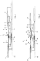
FIG. 2 shows in diagrammatic axial section a breaker according to the invention in the electrically closed state; -
FIG. 3 shows in diagrammatic axial section the main elements of a breaker according to the invention in the electrically closed state; -
FIG. 4 shows in diagrammatic axial section the main elements of a breaker according to the invention in the electrically open state; -
FIG. 5 shows in diagrammatic axial section the main elements of a breaker according to the invention with its disconnecting switch electrically open. - As seen in
figure 2 , the breaker according to theinvention 24 has a general structure which is closed to the structure of the known breaker shown infigure 1 . - The breaker according to the invention also comprises a first and a
second chassis chassis 26 tochassis 27. - The
first chassis 26 carries anassembly 28 comprising acylinder 29 and a fixedrod arcing contact 31, both coaxial with axis AX. Thesecond chassis 27 carries amobile assembly 32 movable along axis AX and which has a shape of revolution around this axis AX. This mobile assembly slides into a corresponding innercylindrical surface 30 of thesecond chassis 27, along longitudinal axis AX. - The
mobile assembly 32 comprises amain body 33 which delimits anannular compression chamber 34 and an annularthermal chamber 36 communicating with the compression chamber, thethermal chamber 36 being contiguous to thecompression chamber 34 along axis AX. It also comprises acircular nozzle 37 made of insulating material such as polytetrafluoroethylene communicating with the thermal chamber, and a hollowmobile arcing contact 38. Thechassis 27 carries afixed piston 39 which closes thecompression chamber 34. - In the example of the figures, the outer wall of the
annular compression chamber 34 is not carried by themobile assembly 32, contrarily to the arrangement of the prior art disclosed infigure 1 : the outer surface of the annular compression chamber is delimited by thecylindrical surface 30 of thesecond chassis 27. - This allows to fixedly secure the
piston 39 directly to the innercylindrical face 30 of thechassis 27, which renders the whole breaker more compact. As seen on the figures, thefixed piston 39 is mostly a flat wall having a circonferential contour. - The
mobile assembly 32 comprises a cylindricalouter wall 40 which forms the outer wall of thethermal chamber 36, and an additionalcylindrical wall 41 which surroundsouter wall 40 of thethermal chamber 36. - This additional
cylindrical wall 41 is a metal part fixedly secured to the mobile assembly, which is a cast part. Theadditional wall 41 is fixed to the mobile assembly by clinching, or by fitting. It can also be threatened to theouter wall 40 or secured thereto in any other way which ensures that electrical current can flow fromwall 40 towall 41. The annular space betweenwall 40 andwall 41 is open by means of a hole or the like to allow gas to freely fill this annular space - This additional
cylindrical wall 41 has a free end inserted in thecylinder 29 ofassembly 28 when the breaker is closed as infigure 2 . The external diameter of this additionalcylindrical wall 41 corresponds to the diameter of innercylindrical surface 30 of thechassis 27, which allows it to fit closely and to slide with themobile assembly 32 in the innercylindrical surface 30 ofsecond chassis 27. - A first permanent sliding
contact 42 has a base fixedly secured to the free end ofcylinder 29 and an extremity applied radially against the free end of additionalcylindrical wall 41 when the breaker is closed. A second permanent slidingcontact 43 has a base fixedly secured to thesecond chassis 27 and an extremity applied radially against theadditional cylinder wall 41 at any position ofassembly 8. - Since the outer face of
additional wall 41 is continuously in electrical contact with the extremity of permanent slidingcontact 43, this outer face is treated appropriately to ensure sufficient level of electrical conductivity with the extremity of the permanent slidingcontact 43. - When the breaker is closed as in
figure 2 , the fixedarcing contact 31 is inserted in themobile arcing contact 38, and the permanent slidingcontact 42 is applied against the free end ofadditional cylinder wall 41. At this stage, most part of the current passes through the permanent slidingcontacts cylindrical wall 41, and a far much lower amount of current flows through arcing contacts. - Upon opening of the breaker,
assembly 32 is moved opposite to thefirst chassis 26. In this movement, the first permanent slidingcontact 42 looses electric connection with the free end ofcylinder 41, resulting in all the current flowing from thesecond chassis 27 to themain body 33 through thepiston 39, in order to pass through arcingcontacts contacts piston chamber 34 by this opening movement and in thethermal chamber 36 due to thermal expansion resulting from the heat generated by the electric arc. The compressed dielectric gas is subsequently blown towards the electric arc throughnozzle 37 to encourage extinguishing of this electric arc. - The device of
figure 2 is both a circuit-breaker and also a disconnecting switch: whenassembly 32 has reach its extreme open position, the other assembly, i.e.assembly 28 can be moved slidably in thefirst chassis 26 to drive the arcingcontact 31 further away from arcingcontact 38 in order to increase the voltage that the open breaker can withstand. - The invention allows the extremity of the permanent sliding contact to be applied against the additional cylindrical wall instead of being applied against the outer wall of the compression chamber. This allows the whole compression chamber carried by the mobile assembly to be located in the region of the cylindrical surface of the chassis for any position of this mobile assembly, resulting in a reduction of the overall length of the breaker.
- It is then possible to choose any outer diameter for the thermal chamber, beneath the diameter of the inner cylindrical surface of the chassis, in order to improve the shape and dimensions of the thermal chamber with respect to the efficiency of the blast to be produced by this thermal chamber. In other words the diameters of the compression chamber and of the thermal chamber can be chosen independently.
- In the prior art arrangements, it was necessary to choose between a thermal chamber having a smaller diameter than the compression chamber which required to increase the length of the breaker, and a thermal chamber having the same diameter as the compression chamber resulting in lower efficiency of the gas blast.
- Generally speaking in this kind of breakers, it is of significant importance to have the ability to choose freely the dimensions of the compression chamber and of the thermal chamber since these dimensions significantly impair the efficiency of the gas blast produced during opening operation to extinguish the electric arc. Most of the time it is expected that the thermal chamber be smaller than the compression chamber and the outer diameter of the cylindrical surface of the main body is given by the size of compression chamber which is chosen.
- In the invention, the outer wall of the thermal chamber and the additional cylindrical wall form a double wall surrounding the thermal chamber, and the extremity of the permanent sliding contact is applied against the outer face of the additional cylindrical wall.
Claims (6)
- A circuit-breaker comprising a chassis (27) having an inner cylindrical surface (30) carrying a mobile assembly (32) :- the mobile assembly (32) being slidably movable relatively to the chassis along a longitudinal axis (AX) of its cylindrical surface (30) between an open position and a closed position ;- the mobile assembly (32) comprising a main body (33) to delimit an annular compression chamber (34) and an annular thermal chamber (36) contiguous to the compression chamber along longitudinal axis (AX) ;- the mobile assembly (32) comprising a cylindrical wall (40) delimiting the thermal chamber (36), the diameter of this cylindrical wall being smaller than the diameter of the cylindrical surface (30) of the chassis ;- a sliding contact (43) fixedly secured to the chassis (27) having an extremity slidably applied radially to the mobile assembly (32) to ensure continuous electric contact between the chassis (27) and the mobile assembly (32);characterized in that:- the mobile assembly comprises an additional cylindrical wall (41) surrounding the cylindrical wall (40) of the thermal chamber (36), this additional cylindrical wall (41) having an outer diameter corresponding to the inner diameter of the cylindrical surface (30) of the chassis (27) ;- the extremity of the sliding contact (43) is applied against the additional cylindrical wall (41) for all the possible positions of the mobile assembly (32) from its open position to its closed position.
- Circuit-breaker according to claim 1 wherein the main body (33) of the mobile assembly comprises the cylindrical wall (40) of the thermal chamber (36) and the additional cylindrical wall surrounding the cylindrical wall of the thermal chamber (36) which are separate elements fixedly secured together.
- Circuit-breaker according to claim 1 or 2, wherein the compression chamber (34) is delimited by the cylindrical surface (30) of the chassis (27).
- Circuit breaker according to claim 1 to 3 arranged to ensure that when the circuit breaker is electrically closed the electric current passes through the additional cylindrical wall (41).
- Circuit-breaker according to claim 1 to 4, wherein the additional wall (41) is made of a material which is different than the material of the main body (33).
- Circuit breaker according to claim 3, comprising a piston (39) closing the compression chamber (34), and wherein this piston (39) is fixed directly to cylindrical surface (30) of the chassis (27).
Priority Applications (2)
| Application Number | Priority Date | Filing Date | Title |
|---|---|---|---|
| EP17290009.4A EP3355332B1 (en) | 2017-01-27 | 2017-01-27 | Circuit breaker comprising a double wall surrounding its thermal chamber |
| PCT/EP2018/051721 WO2018138144A1 (en) | 2017-01-27 | 2018-01-24 | Circuit breaker comprising a double wall surrounding its thermal chamber |
Applications Claiming Priority (1)
| Application Number | Priority Date | Filing Date | Title |
|---|---|---|---|
| EP17290009.4A EP3355332B1 (en) | 2017-01-27 | 2017-01-27 | Circuit breaker comprising a double wall surrounding its thermal chamber |
Publications (2)
| Publication Number | Publication Date |
|---|---|
| EP3355332A1 true EP3355332A1 (en) | 2018-08-01 |
| EP3355332B1 EP3355332B1 (en) | 2020-02-26 |
Family
ID=58054078
Family Applications (1)
| Application Number | Title | Priority Date | Filing Date |
|---|---|---|---|
| EP17290009.4A Active EP3355332B1 (en) | 2017-01-27 | 2017-01-27 | Circuit breaker comprising a double wall surrounding its thermal chamber |
Country Status (2)
| Country | Link |
|---|---|
| EP (1) | EP3355332B1 (en) |
| WO (1) | WO2018138144A1 (en) |
Citations (2)
| Publication number | Priority date | Publication date | Assignee | Title |
|---|---|---|---|---|
| US4450329A (en) * | 1981-05-19 | 1984-05-22 | Mitsubishi Denki Kabushiki Kaisha | Gas circuit breaker |
| US4577074A (en) * | 1984-01-13 | 1986-03-18 | Alsthom-Atlantique | High voltage gas-blast circuit breaker |
-
2017
- 2017-01-27 EP EP17290009.4A patent/EP3355332B1/en active Active
-
2018
- 2018-01-24 WO PCT/EP2018/051721 patent/WO2018138144A1/en not_active Ceased
Patent Citations (2)
| Publication number | Priority date | Publication date | Assignee | Title |
|---|---|---|---|---|
| US4450329A (en) * | 1981-05-19 | 1984-05-22 | Mitsubishi Denki Kabushiki Kaisha | Gas circuit breaker |
| US4577074A (en) * | 1984-01-13 | 1986-03-18 | Alsthom-Atlantique | High voltage gas-blast circuit breaker |
Also Published As
| Publication number | Publication date |
|---|---|
| WO2018138144A1 (en) | 2018-08-02 |
| EP3355332B1 (en) | 2020-02-26 |
Similar Documents
| Publication | Publication Date | Title |
|---|---|---|
| CN102117713A (en) | Gas-isolated high voltage switch | |
| US20150170858A1 (en) | Gas Circuit Breaker | |
| EP3200214A1 (en) | Gas insulated circuit breaker | |
| CN112074923B (en) | Gas-insulated medium-voltage switchgear with shielding device | |
| KR101919125B1 (en) | Gas insulated switch device of high voltage distributer | |
| US9384924B2 (en) | Gas circuit breaker | |
| US11373824B2 (en) | Gas-insulated high or medium voltage circuit breaker | |
| EP2822017A1 (en) | High voltage gas circuit breaker | |
| US20170352509A1 (en) | High-voltage electrical circuit breaker device with optimised automatic extinction | |
| EP3355332B1 (en) | Circuit breaker comprising a double wall surrounding its thermal chamber | |
| US11062862B2 (en) | Gas-insulated high or medium voltage circuit breaker | |
| EP4141901B1 (en) | Metal enclosed circuit breaker | |
| JP2018113189A (en) | Gas circuit breaker | |
| JP4377551B2 (en) | Gas circuit breaker | |
| EP4117006B1 (en) | Gas-insulated high or medium voltage circuit breaker | |
| US11217408B2 (en) | Gas circuit breaker | |
| JPS6336589Y2 (en) | ||
| JP7842882B2 (en) | High-speed earthing switch for interrupting non-short-circuit currents | |
| JP2015082368A (en) | Gas circuit breaker | |
| US11227735B2 (en) | Gas circuit breaker | |
| JP2014186796A (en) | Gas circuit breaker | |
| JP2013171803A (en) | Gas circuit breaker |
Legal Events
| Date | Code | Title | Description |
|---|---|---|---|
| PUAI | Public reference made under article 153(3) epc to a published international application that has entered the european phase |
Free format text: ORIGINAL CODE: 0009012 |
|
| STAA | Information on the status of an ep patent application or granted ep patent |
Free format text: STATUS: THE APPLICATION HAS BEEN PUBLISHED |
|
| AK | Designated contracting states |
Kind code of ref document: A1 Designated state(s): AL AT BE BG CH CY CZ DE DK EE ES FI FR GB GR HR HU IE IS IT LI LT LU LV MC MK MT NL NO PL PT RO RS SE SI SK SM TR |
|
| AX | Request for extension of the european patent |
Extension state: BA ME |
|
| STAA | Information on the status of an ep patent application or granted ep patent |
Free format text: STATUS: REQUEST FOR EXAMINATION WAS MADE |
|
| 17P | Request for examination filed |
Effective date: 20190201 |
|
| RBV | Designated contracting states (corrected) |
Designated state(s): AL AT BE BG CH CY CZ DE DK EE ES FI FR GB GR HR HU IE IS IT LI LT LU LV MC MK MT NL NO PL PT RO RS SE SI SK SM TR |
|
| GRAP | Despatch of communication of intention to grant a patent |
Free format text: ORIGINAL CODE: EPIDOSNIGR1 |
|
| STAA | Information on the status of an ep patent application or granted ep patent |
Free format text: STATUS: GRANT OF PATENT IS INTENDED |
|
| INTG | Intention to grant announced |
Effective date: 20190906 |
|
| GRAS | Grant fee paid |
Free format text: ORIGINAL CODE: EPIDOSNIGR3 |
|
| GRAA | (expected) grant |
Free format text: ORIGINAL CODE: 0009210 |
|
| STAA | Information on the status of an ep patent application or granted ep patent |
Free format text: STATUS: THE PATENT HAS BEEN GRANTED |
|
| AK | Designated contracting states |
Kind code of ref document: B1 Designated state(s): AL AT BE BG CH CY CZ DE DK EE ES FI FR GB GR HR HU IE IS IT LI LT LU LV MC MK MT NL NO PL PT RO RS SE SI SK SM TR |
|
| REG | Reference to a national code |
Ref country code: GB Ref legal event code: FG4D |
|
| REG | Reference to a national code |
Ref country code: CH Ref legal event code: EP |
|
| REG | Reference to a national code |
Ref country code: CH Ref legal event code: NV Representative=s name: VALIPAT S.A. C/O BOVARD SA NEUCHATEL, CH |
|
| REG | Reference to a national code |
Ref country code: AT Ref legal event code: REF Ref document number: 1238651 Country of ref document: AT Kind code of ref document: T Effective date: 20200315 |
|
| REG | Reference to a national code |
Ref country code: IE Ref legal event code: FG4D |
|
| REG | Reference to a national code |
Ref country code: DE Ref legal event code: R096 Ref document number: 602017012243 Country of ref document: DE |
|
| REG | Reference to a national code |
Ref country code: SE Ref legal event code: TRGR |
|
| PG25 | Lapsed in a contracting state [announced via postgrant information from national office to epo] |
Ref country code: FI Free format text: LAPSE BECAUSE OF FAILURE TO SUBMIT A TRANSLATION OF THE DESCRIPTION OR TO PAY THE FEE WITHIN THE PRESCRIBED TIME-LIMIT Effective date: 20200226 Ref country code: NO Free format text: LAPSE BECAUSE OF FAILURE TO SUBMIT A TRANSLATION OF THE DESCRIPTION OR TO PAY THE FEE WITHIN THE PRESCRIBED TIME-LIMIT Effective date: 20200526 Ref country code: RS Free format text: LAPSE BECAUSE OF FAILURE TO SUBMIT A TRANSLATION OF THE DESCRIPTION OR TO PAY THE FEE WITHIN THE PRESCRIBED TIME-LIMIT Effective date: 20200226 |
|
| REG | Reference to a national code |
Ref country code: NL Ref legal event code: MP Effective date: 20200226 |
|
| REG | Reference to a national code |
Ref country code: LT Ref legal event code: MG4D |
|
| PG25 | Lapsed in a contracting state [announced via postgrant information from national office to epo] |
Ref country code: GR Free format text: LAPSE BECAUSE OF FAILURE TO SUBMIT A TRANSLATION OF THE DESCRIPTION OR TO PAY THE FEE WITHIN THE PRESCRIBED TIME-LIMIT Effective date: 20200527 Ref country code: IS Free format text: LAPSE BECAUSE OF FAILURE TO SUBMIT A TRANSLATION OF THE DESCRIPTION OR TO PAY THE FEE WITHIN THE PRESCRIBED TIME-LIMIT Effective date: 20200626 Ref country code: BG Free format text: LAPSE BECAUSE OF FAILURE TO SUBMIT A TRANSLATION OF THE DESCRIPTION OR TO PAY THE FEE WITHIN THE PRESCRIBED TIME-LIMIT Effective date: 20200526 Ref country code: LV Free format text: LAPSE BECAUSE OF FAILURE TO SUBMIT A TRANSLATION OF THE DESCRIPTION OR TO PAY THE FEE WITHIN THE PRESCRIBED TIME-LIMIT Effective date: 20200226 Ref country code: HR Free format text: LAPSE BECAUSE OF FAILURE TO SUBMIT A TRANSLATION OF THE DESCRIPTION OR TO PAY THE FEE WITHIN THE PRESCRIBED TIME-LIMIT Effective date: 20200226 |
|
| PG25 | Lapsed in a contracting state [announced via postgrant information from national office to epo] |
Ref country code: NL Free format text: LAPSE BECAUSE OF FAILURE TO SUBMIT A TRANSLATION OF THE DESCRIPTION OR TO PAY THE FEE WITHIN THE PRESCRIBED TIME-LIMIT Effective date: 20200226 |
|
| PG25 | Lapsed in a contracting state [announced via postgrant information from national office to epo] |
Ref country code: CZ Free format text: LAPSE BECAUSE OF FAILURE TO SUBMIT A TRANSLATION OF THE DESCRIPTION OR TO PAY THE FEE WITHIN THE PRESCRIBED TIME-LIMIT Effective date: 20200226 Ref country code: ES Free format text: LAPSE BECAUSE OF FAILURE TO SUBMIT A TRANSLATION OF THE DESCRIPTION OR TO PAY THE FEE WITHIN THE PRESCRIBED TIME-LIMIT Effective date: 20200226 Ref country code: LT Free format text: LAPSE BECAUSE OF FAILURE TO SUBMIT A TRANSLATION OF THE DESCRIPTION OR TO PAY THE FEE WITHIN THE PRESCRIBED TIME-LIMIT Effective date: 20200226 Ref country code: EE Free format text: LAPSE BECAUSE OF FAILURE TO SUBMIT A TRANSLATION OF THE DESCRIPTION OR TO PAY THE FEE WITHIN THE PRESCRIBED TIME-LIMIT Effective date: 20200226 Ref country code: SM Free format text: LAPSE BECAUSE OF FAILURE TO SUBMIT A TRANSLATION OF THE DESCRIPTION OR TO PAY THE FEE WITHIN THE PRESCRIBED TIME-LIMIT Effective date: 20200226 Ref country code: DK Free format text: LAPSE BECAUSE OF FAILURE TO SUBMIT A TRANSLATION OF THE DESCRIPTION OR TO PAY THE FEE WITHIN THE PRESCRIBED TIME-LIMIT Effective date: 20200226 Ref country code: PT Free format text: LAPSE BECAUSE OF FAILURE TO SUBMIT A TRANSLATION OF THE DESCRIPTION OR TO PAY THE FEE WITHIN THE PRESCRIBED TIME-LIMIT Effective date: 20200719 Ref country code: SK Free format text: LAPSE BECAUSE OF FAILURE TO SUBMIT A TRANSLATION OF THE DESCRIPTION OR TO PAY THE FEE WITHIN THE PRESCRIBED TIME-LIMIT Effective date: 20200226 Ref country code: RO Free format text: LAPSE BECAUSE OF FAILURE TO SUBMIT A TRANSLATION OF THE DESCRIPTION OR TO PAY THE FEE WITHIN THE PRESCRIBED TIME-LIMIT Effective date: 20200226 |
|
| REG | Reference to a national code |
Ref country code: AT Ref legal event code: MK05 Ref document number: 1238651 Country of ref document: AT Kind code of ref document: T Effective date: 20200226 |
|
| REG | Reference to a national code |
Ref country code: DE Ref legal event code: R097 Ref document number: 602017012243 Country of ref document: DE |
|
| PLBE | No opposition filed within time limit |
Free format text: ORIGINAL CODE: 0009261 |
|
| STAA | Information on the status of an ep patent application or granted ep patent |
Free format text: STATUS: NO OPPOSITION FILED WITHIN TIME LIMIT |
|
| PG25 | Lapsed in a contracting state [announced via postgrant information from national office to epo] |
Ref country code: IT Free format text: LAPSE BECAUSE OF FAILURE TO SUBMIT A TRANSLATION OF THE DESCRIPTION OR TO PAY THE FEE WITHIN THE PRESCRIBED TIME-LIMIT Effective date: 20200226 Ref country code: AT Free format text: LAPSE BECAUSE OF FAILURE TO SUBMIT A TRANSLATION OF THE DESCRIPTION OR TO PAY THE FEE WITHIN THE PRESCRIBED TIME-LIMIT Effective date: 20200226 |
|
| 26N | No opposition filed |
Effective date: 20201127 |
|
| PG25 | Lapsed in a contracting state [announced via postgrant information from national office to epo] |
Ref country code: PL Free format text: LAPSE BECAUSE OF FAILURE TO SUBMIT A TRANSLATION OF THE DESCRIPTION OR TO PAY THE FEE WITHIN THE PRESCRIBED TIME-LIMIT Effective date: 20200226 Ref country code: SI Free format text: LAPSE BECAUSE OF FAILURE TO SUBMIT A TRANSLATION OF THE DESCRIPTION OR TO PAY THE FEE WITHIN THE PRESCRIBED TIME-LIMIT Effective date: 20200226 |
|
| PG25 | Lapsed in a contracting state [announced via postgrant information from national office to epo] |
Ref country code: MC Free format text: LAPSE BECAUSE OF FAILURE TO SUBMIT A TRANSLATION OF THE DESCRIPTION OR TO PAY THE FEE WITHIN THE PRESCRIBED TIME-LIMIT Effective date: 20200226 |
|
| GBPC | Gb: european patent ceased through non-payment of renewal fee |
Effective date: 20210127 |
|
| PG25 | Lapsed in a contracting state [announced via postgrant information from national office to epo] |
Ref country code: LU Free format text: LAPSE BECAUSE OF NON-PAYMENT OF DUE FEES Effective date: 20210127 |
|
| REG | Reference to a national code |
Ref country code: BE Ref legal event code: MM Effective date: 20210131 |
|
| PG25 | Lapsed in a contracting state [announced via postgrant information from national office to epo] |
Ref country code: FR Free format text: LAPSE BECAUSE OF NON-PAYMENT OF DUE FEES Effective date: 20210131 |
|
| PG25 | Lapsed in a contracting state [announced via postgrant information from national office to epo] |
Ref country code: GB Free format text: LAPSE BECAUSE OF NON-PAYMENT OF DUE FEES Effective date: 20210127 |
|
| PG25 | Lapsed in a contracting state [announced via postgrant information from national office to epo] |
Ref country code: IE Free format text: LAPSE BECAUSE OF NON-PAYMENT OF DUE FEES Effective date: 20210127 |
|
| PG25 | Lapsed in a contracting state [announced via postgrant information from national office to epo] |
Ref country code: BE Free format text: LAPSE BECAUSE OF NON-PAYMENT OF DUE FEES Effective date: 20210131 |
|
| P01 | Opt-out of the competence of the unified patent court (upc) registered |
Effective date: 20230522 |
|
| PG25 | Lapsed in a contracting state [announced via postgrant information from national office to epo] |
Ref country code: CY Free format text: LAPSE BECAUSE OF FAILURE TO SUBMIT A TRANSLATION OF THE DESCRIPTION OR TO PAY THE FEE WITHIN THE PRESCRIBED TIME-LIMIT Effective date: 20200226 |
|
| PG25 | Lapsed in a contracting state [announced via postgrant information from national office to epo] |
Ref country code: HU Free format text: LAPSE BECAUSE OF FAILURE TO SUBMIT A TRANSLATION OF THE DESCRIPTION OR TO PAY THE FEE WITHIN THE PRESCRIBED TIME-LIMIT; INVALID AB INITIO Effective date: 20170127 |
|
| PG25 | Lapsed in a contracting state [announced via postgrant information from national office to epo] |
Ref country code: MK Free format text: LAPSE BECAUSE OF FAILURE TO SUBMIT A TRANSLATION OF THE DESCRIPTION OR TO PAY THE FEE WITHIN THE PRESCRIBED TIME-LIMIT Effective date: 20200226 |
|
| PG25 | Lapsed in a contracting state [announced via postgrant information from national office to epo] |
Ref country code: TR Free format text: LAPSE BECAUSE OF FAILURE TO SUBMIT A TRANSLATION OF THE DESCRIPTION OR TO PAY THE FEE WITHIN THE PRESCRIBED TIME-LIMIT Effective date: 20200226 |
|
| PG25 | Lapsed in a contracting state [announced via postgrant information from national office to epo] |
Ref country code: MT Free format text: LAPSE BECAUSE OF FAILURE TO SUBMIT A TRANSLATION OF THE DESCRIPTION OR TO PAY THE FEE WITHIN THE PRESCRIBED TIME-LIMIT Effective date: 20200226 |
|
| PGFP | Annual fee paid to national office [announced via postgrant information from national office to epo] |
Ref country code: SE Payment date: 20251217 Year of fee payment: 10 |
|
| REG | Reference to a national code |
Ref country code: CH Ref legal event code: U11 Free format text: ST27 STATUS EVENT CODE: U-0-0-U10-U11 (AS PROVIDED BY THE NATIONAL OFFICE) Effective date: 20260201 |
|
| PGFP | Annual fee paid to national office [announced via postgrant information from national office to epo] |
Ref country code: DE Payment date: 20251217 Year of fee payment: 10 |
|
| PGFP | Annual fee paid to national office [announced via postgrant information from national office to epo] |
Ref country code: CH Payment date: 20260201 Year of fee payment: 10 |