EP3355323A1 - Cooling assembly for a high voltage assembly and method to operate a cooling assembly for a high voltage assembly - Google Patents
Cooling assembly for a high voltage assembly and method to operate a cooling assembly for a high voltage assembly Download PDFInfo
- Publication number
- EP3355323A1 EP3355323A1 EP17153608.9A EP17153608A EP3355323A1 EP 3355323 A1 EP3355323 A1 EP 3355323A1 EP 17153608 A EP17153608 A EP 17153608A EP 3355323 A1 EP3355323 A1 EP 3355323A1
- Authority
- EP
- European Patent Office
- Prior art keywords
- assembly
- cooling assembly
- flow rate
- volumetric flow
- high voltage
- Prior art date
- Legal status (The legal status is an assumption and is not a legal conclusion. Google has not performed a legal analysis and makes no representation as to the accuracy of the status listed.)
- Withdrawn
Links
Images

Classifications
-
- H—ELECTRICITY
- H01—ELECTRIC ELEMENTS
- H01F—MAGNETS; INDUCTANCES; TRANSFORMERS; SELECTION OF MATERIALS FOR THEIR MAGNETIC PROPERTIES
- H01F27/00—Details of transformers or inductances, in general
- H01F27/08—Cooling; Ventilating
- H01F27/10—Liquid cooling
- H01F27/12—Oil cooling
Definitions
- the present invention relates to a cooling assembly for a high voltage assembly and to a method to operate the cooling assembly.
- Known high voltage assemblies like oil immersed power transformers or oil immersed reactors comprise a cooling assembly which is adapted to an expected ambient temperature range and adapted to the configuration of the high voltage assembly. Furthermore, it is known that such a cooling assembly comprises a pump which comprises an on-state and an off-state only.
- a cooling assembly for connecting to a compartment of a high voltage assembly via a flow line and a return line, the cooling assembly comprises a heat exchange assembly adapted to dissipate heat from the insulation liquid to the environment; and a pump arranged at the flow line or the return line and being operable at variable speeds.
- the cooling power of the heat exchange assembly can be adapted as it is available a continuously variable speed control of the pump. Therefore, the cooling performance can be optimized and an increase in overload capacity is possible. Furthermore, unnecessary losses are avoided as the pump can be operated at less than 100 % of the possible speed. Also inrush currents are limited as the variable speed control allows starting the pump with a low speed.
- the proposed cooling assembly also provides to decrease weight and dimension of the cooling assembly as forced circulation through the cooling assembly does not rely on natural convection which would implicate large surfaces exposed to the environment.
- a further advantage relies in standardization, which means that one type of pump can be used for a plurality of speed and sound requirements. Consequently, one type of pump can be used for a plurality of types of high voltage assemblies. This has also an advantageous impact on the reduction of service and maintenance costs.
- An advantageous embodiment is characterized in that a target volumetric flow rate of the insulation liquid is determined, wherein the speed of the pump is controlled in dependence on the target volumetric flow rate.
- An advantageous embodiment is characterized in that the target volumetric flow rate is determined in dependence on a load current of the high voltage assembly. Consequently, temperature variations of the insulation liquid over time can be reduced. This results in less breathing of the high voltage assembly which has a positive effect on ageing of the whole oil/paper-insulation. Therefore life expectancy of the whole high voltage assembly is increased.
- An advantageous embodiment is characterized in that the target volumetric flow rate is determined in dependence on a temperature of the insulation liquid. Consequently, temperature variations of the insulation liquid over time can be reduced. This results in less breathing of the high voltage assembly which has a positive effect on ageing of the whole oil/paper-insulation. Therefore life expectancy of the whole high voltage assembly is increased.
- An advantageous embodiment is characterized in that the target volumetric flow rate is determined to a base rate if the temperature and/or the load current falls below a threshold.
- the base rate advantageously provides that any failure of the pump can be detected and resolved immediately.
- the insulation liquid remains in circulation.
- sound emissions of the pump or cooling fans are reduced when compared to a singular on-state.
- An advantageous embodiment is characterized in that the target volumetric flow rate is determined in dependence on a characteristic curve linking the target volumetric flow rate and the temperature of the insulation liquid or the target volumetric flow rate and the load current.
- An advantageous embodiment is characterized in that the characteristic curve comprises partly a linear relationship between the target volumetric flow rate and the temperature of the insulation liquid or the target volumetric flow rate and the load current.
- An advantageous embodiment is characterized in that the target volumetric flow rate is determined in dependence on a manual input of a manual input unit, wherein the manual input overrides the calculated target volumetric flow rate. Therefore, manual operation is advantageously is still possible.
- An advantageous embodiment is characterized in that the target volumetric flow rate is determined by a closed loop control. A further reduction in temporal drift of the temperature of the insulation liquid can be achieved.
- cooling assembly comprises a radiator, and wherein the pump is a propeller pump.
- cooling assembly comprises an oil-to-air-cooler or an oil-to-water cooler, and wherein the pump is an inline pump.
- a high voltage assembly comprising the proposed cooling assembly, and the compartment containing an active component surrounded by the insulation liquid, wherein the cooling assembly is connected with the compartment via the flow line and the return line.
- Another aspect of this disclosure is directed to a method to operate a cooling assembly for a high voltage assembly being connected to a compartment of the high voltage assembly via a flow line and a return line, the cooling assembly comprising: a heat exchange assembly adapted to dissipate heat from the insulation liquid to the environment; and the method comprising operating a pump arranged at the flow line or the return line at variable speeds.
- a further aspect of this disclosure is directed to a control unit configured to execute the proposed method.
- FIG. 1 shows a schematic depiction of a cooling assembly 2 for a high voltage assembly.
- the cooling assembly 2 is adapted to be connected to a compartment of the high voltage assembly via a flow line 4 and a return line 6.
- a heat exchange assembly 8 is adapted to dissipate heat from an insulation liquid 10 passing through the heat exchange assembly 8 to the environment 12.
- a pump 14 is arranged at the flow line 4 and is operable at variable speeds.
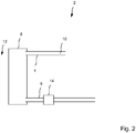
- Figure 2 shows a further schematic cooling assembly 2 for a high voltage assembly. With difference to figure 1 the pump 14 is arranged at the return line 6.
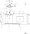
- FIG. 3 shows schematic depiction of the high voltage assembly 16.
- the high voltage assembly 16 is for example a high voltage transformer or a high voltage reactor.
- the heat exchange assembly 8 comprises a heat dissipating component 9 like a radiator or an oil-to-air-cooler or an oil-to-water-cooler.
- the heat exchange assembly 8 realizes an insulation liquid path 11 to ingest high temperature insulation liquid 10 and to emit low temperature insulation liquid 10 into the compartment 18.
- an active component 20 comprising a core and windings.
- the active component 20 is surrounded by the insulation liquid 10.
- An inlet 22 of the flow line 4 is arranged at an upper part 24 of the compartment 18.
- An outlet 26 of the return line 6 is arranged at a bottom part 28 of the and inside the compartment 18.
- the outlet 26 is arranged below the active component 20.
- the outlet 26 can be arranged outside an area below the active component 20.
- the outlet 26 can be arranged to pass at least partly through the active component 20.
- a controller 30 is configured to determine a target volumetric flow rate ft. To determine the target volumetric flow rate ft the controller 30 comprises a processor P and memory MEM. A temperature sensor 32 is arranged at the flow line 4 to determine a temperature T of the insulation liquid 10 passing through the flow line 4.
- the temperature sensor 32 can be arranged at another position of the high voltage assembly 16.
- a unit 34 is configured to determine a load current I of the high voltage assembly 16.
- the unit 34 can be a sensor or a further control unit.
- a manual input unit 36 determines a manual input M.
- the controller 30 is configured to determine the target volumetric flow rate ft in dependence on the temperature T and/or the load current I and/or in dependence on the manual input M.
- the pump 14 comprises power electronics 38 to which the target volumetric flow rate ft is applied.
- the power electronics 38 is configured to translate the applied target volumetric flow rate ft to a corresponding speed of the pump 14.
- the high voltage assembly 16 comprises a plurality of cooling assemblies 2, each cooling assembly 2 being connected to the single compartment 18 via a respective flow line 4 and a respective return line 6.
- the plurality of assemblies 2 is connected to the single compartment 19 via an at least partly conjoint flow line 4 and an at least partly conjoint return line 6.
- the cooling of the insulation liquid 10 is assured by redundant cooling assemblies 2.
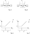
- FIG. 4 shows schematic block diagram of open-loop control.
- the temperature T is supplied to a characteristic curve 40 and a corresponding target volumetric flow rate ft is determined and applied to the pump 14.
- Figure 5 shows the characteristic curve 40 in a schematic way.
- the target volumetric flow rate ft remains constant at a base rate ftB.
- a linear relationship between the temperature T and the target volumetric flow rate ft applies.
- a threshold Tth divides the temperature areas TA and TB.
- the relationship between the temperature T and the target volumetric flow rate ft can depart from the linear relationship in the temperature area TB.
- Figure 6 shows schematic block diagram of open-loop control.
- the load current I is supplied to a characteristic curve 42.
- a target volumetric flow rate ft corresponding to the load current I is determined and applied to the pump 14.
- Figure 7 shows the characteristic curve 42 in a schematic way.
- a first load current area IA the target volumetric flow rate ft remains constant at a base rate ftB.
- a second load current area TB a linear relationship between the load current I and the target volumetric flow rate ft applies.
- a threshold Ith divides the load current areas IA and IB.
- relationship between the load current I and the target volumetric flow rate ft can depart from the linear relationship in the load current area IB.
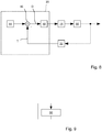
- FIG. 8 shows a schematic block diagram of a closed loop control.
- a block 44 determines a setpoint value Ts as a desired value for the temperature of the insulation liquid 10 inside the compartment 18 or a temperature of the insulation liquid 10 at the temperature sensor 32.
- a difference D is determined by subtracting the temperature T from the setpoint value Ts.
- the difference d is applied to a controller 48, for example a proportional plus integral plus derivative element.
- the controller 48 determines the target volumetric flow rate ft in dependence on the difference D and applies it to the pump 14.
- the operation of the pump 14 at variable speeds has an impact on the whole high voltage assembly 16 which can be measured by the temperature T.
- Figure 9 shows a schematic flow diagram to operate the cooling assembly 2.
- the pump 14 is operated at variable speeds.
Landscapes
- Engineering & Computer Science (AREA)
- Power Engineering (AREA)
- Cooling Or The Like Of Electrical Apparatus (AREA)
- Transformer Cooling (AREA)
Abstract
Description
- The present invention relates to a cooling assembly for a high voltage assembly and to a method to operate the cooling assembly.
- Known high voltage assemblies like oil immersed power transformers or oil immersed reactors comprise a cooling assembly which is adapted to an expected ambient temperature range and adapted to the configuration of the high voltage assembly. Furthermore, it is known that such a cooling assembly comprises a pump which comprises an on-state and an off-state only.
- Furthermore, legislative authorities push the need for "green" transformers implicating that unnecessary energy consumption is avoided.
- In view of the prior art, it is an object of the present disclosure to improve a cooling assembly for a high voltage assembly and a method to operate a cooling assembly for a high voltage assembly.
- According to a first aspect of this disclosure it is proposed a cooling assembly for connecting to a compartment of a high voltage assembly via a flow line and a return line, the cooling assembly comprises a heat exchange assembly adapted to dissipate heat from the insulation liquid to the environment; and a pump arranged at the flow line or the return line and being operable at variable speeds.
- Advantageously the cooling power of the heat exchange assembly can be adapted as it is available a continuously variable speed control of the pump. Therefore, the cooling performance can be optimized and an increase in overload capacity is possible. Furthermore, unnecessary losses are avoided as the pump can be operated at less than 100 % of the possible speed. Also inrush currents are limited as the variable speed control allows starting the pump with a low speed. The proposed cooling assembly also provides to decrease weight and dimension of the cooling assembly as forced circulation through the cooling assembly does not rely on natural convection which would implicate large surfaces exposed to the environment.
- A further advantage relies in standardization, which means that one type of pump can be used for a plurality of speed and sound requirements. Consequently, one type of pump can be used for a plurality of types of high voltage assemblies. This has also an advantageous impact on the reduction of service and maintenance costs.
- An advantageous embodiment is characterized in that a target volumetric flow rate of the insulation liquid is determined, wherein the speed of the pump is controlled in dependence on the target volumetric flow rate.
- An advantageous embodiment is characterized in that the target volumetric flow rate is determined in dependence on a load current of the high voltage assembly. Consequently, temperature variations of the insulation liquid over time can be reduced. This results in less breathing of the high voltage assembly which has a positive effect on ageing of the whole oil/paper-insulation. Therefore life expectancy of the whole high voltage assembly is increased.
- An advantageous embodiment is characterized in that the target volumetric flow rate is determined in dependence on a temperature of the insulation liquid. Consequently, temperature variations of the insulation liquid over time can be reduced. This results in less breathing of the high voltage assembly which has a positive effect on ageing of the whole oil/paper-insulation. Therefore life expectancy of the whole high voltage assembly is increased.
- An advantageous embodiment is characterized in that the target volumetric flow rate is determined to a base rate if the temperature and/or the load current falls below a threshold. Compared with an off-state of the pump the base rate advantageously provides that any failure of the pump can be detected and resolved immediately. Furthermore, the insulation liquid remains in circulation. Moreover, sound emissions of the pump or cooling fans are reduced when compared to a singular on-state.
- An advantageous embodiment is characterized in that the target volumetric flow rate is determined in dependence on a characteristic curve linking the target volumetric flow rate and the temperature of the insulation liquid or the target volumetric flow rate and the load current.
- An advantageous embodiment is characterized in that the characteristic curve comprises partly a linear relationship between the target volumetric flow rate and the temperature of the insulation liquid or the target volumetric flow rate and the load current.
- An advantageous embodiment is characterized in that the target volumetric flow rate is determined in dependence on a manual input of a manual input unit, wherein the manual input overrides the calculated target volumetric flow rate. Therefore, manual operation is advantageously is still possible.
- An advantageous embodiment is characterized in that the target volumetric flow rate is determined by a closed loop control. A further reduction in temporal drift of the temperature of the insulation liquid can be achieved.
- An advantageous embodiment is characterized in that the cooling assembly comprises a radiator, and wherein the pump is a propeller pump.
- An advantageous embodiment is characterized in that the cooling assembly comprises an oil-to-air-cooler or an oil-to-water cooler, and wherein the pump is an inline pump. Another aspect of this disclosure is directed to a high voltage assembly comprising the proposed cooling assembly, and the compartment containing an active component surrounded by the insulation liquid, wherein the cooling assembly is connected with the compartment via the flow line and the return line.
- Another aspect of this disclosure is directed to a method to operate a cooling assembly for a high voltage assembly being connected to a compartment of the high voltage assembly via a flow line and a return line, the cooling assembly comprising: a heat exchange assembly adapted to dissipate heat from the insulation liquid to the environment; and the method comprising operating a pump arranged at the flow line or the return line at variable speeds. The advantages of the method are outlined above.
- A further aspect of this disclosure is directed to a control unit configured to execute the proposed method.
-
-
Figures 1 and3 show a schematic cooling assembly for a high voltage assembly, respectively; -
Figure 3 shows schematic depiction of the high voltage assembly; -
Figures 4 and 6 show a schematic block diagram of open-loop control, respectively; -
Figures 5 and 7 show a characteristic curve, respectively; -
Figure 8 shows a schematic block diagram of a closed loop control; and -
Figure 9 shows a schematic flow diagram. -
Figure 1 shows a schematic depiction of acooling assembly 2 for a high voltage assembly. Thecooling assembly 2 is adapted to be connected to a compartment of the high voltage assembly via aflow line 4 and areturn line 6. Aheat exchange assembly 8 is adapted to dissipate heat from aninsulation liquid 10 passing through theheat exchange assembly 8 to theenvironment 12. Apump 14 is arranged at theflow line 4 and is operable at variable speeds. -
Figure 2 shows a furtherschematic cooling assembly 2 for a high voltage assembly. With difference tofigure 1 thepump 14 is arranged at thereturn line 6. -
Figure 3 shows schematic depiction of thehigh voltage assembly 16. Thehigh voltage assembly 16 is for example a high voltage transformer or a high voltage reactor. Theheat exchange assembly 8 comprises aheat dissipating component 9 like a radiator or an oil-to-air-cooler or an oil-to-water-cooler. Theheat exchange assembly 8 realizes an insulationliquid path 11 to ingest hightemperature insulation liquid 10 and to emit lowtemperature insulation liquid 10 into thecompartment 18. Inside thecompartment 18 of thehigh voltage assembly 16 it is arranged anactive component 20 comprising a core and windings. Theactive component 20 is surrounded by theinsulation liquid 10. - An
inlet 22 of theflow line 4 is arranged at anupper part 24 of thecompartment 18. Anoutlet 26 of thereturn line 6 is arranged at abottom part 28 of the and inside thecompartment 18. Theoutlet 26 is arranged below theactive component 20. According to another embodiment theoutlet 26 can be arranged outside an area below theactive component 20. According to a further embodiment theoutlet 26 can be arranged to pass at least partly through theactive component 20. - A
controller 30 is configured to determine a target volumetric flow rate ft. To determine the target volumetric flow rate ft thecontroller 30 comprises a processor P and memory MEM. Atemperature sensor 32 is arranged at theflow line 4 to determine a temperature T of theinsulation liquid 10 passing through theflow line 4. - Of course, the
temperature sensor 32 can be arranged at another position of thehigh voltage assembly 16. Aunit 34 is configured to determine a load current I of thehigh voltage assembly 16. Theunit 34 can be a sensor or a further control unit. Amanual input unit 36 determines a manual input M. Thecontroller 30 is configured to determine the target volumetric flow rate ft in dependence on the temperature T and/or the load current I and/or in dependence on the manual input M. - The
pump 14 comprises power electronics 38 to which the target volumetric flow rate ft is applied. The power electronics 38 is configured to translate the applied target volumetric flow rate ft to a corresponding speed of thepump 14. - According to an embodiment the
high voltage assembly 16 comprises a plurality ofcooling assemblies 2, each coolingassembly 2 being connected to thesingle compartment 18 via arespective flow line 4 and arespective return line 6. Alternatively, the plurality ofassemblies 2 is connected to the single compartment 19 via an at least partlyconjoint flow line 4 and an at least partlyconjoint return line 6. Advantageously, the cooling of theinsulation liquid 10 is assured byredundant cooling assemblies 2. -
Figure 4 shows schematic block diagram of open-loop control. The temperature T is supplied to acharacteristic curve 40 and a corresponding target volumetric flow rate ft is determined and applied to thepump 14. -
Figure 5 shows thecharacteristic curve 40 in a schematic way. In a first temperature area TA the target volumetric flow rate ft remains constant at a base rate ftB. In a second temperature area TB a linear relationship between the temperature T and the target volumetric flow rate ft applies. A threshold Tth divides the temperature areas TA and TB. Of course, the relationship between the temperature T and the target volumetric flow rate ft can depart from the linear relationship in the temperature area TB. -
Figure 6 shows schematic block diagram of open-loop control. The load current I is supplied to acharacteristic curve 42. A target volumetric flow rate ft corresponding to the load current I is determined and applied to thepump 14. -
Figure 7 shows thecharacteristic curve 42 in a schematic way. In a first load current area IA the target volumetric flow rate ft remains constant at a base rate ftB. In a second load current area TB a linear relationship between the load current I and the target volumetric flow rate ft applies. A threshold Ith divides the load current areas IA and IB. Of course, relationship between the load current I and the target volumetric flow rate ft can depart from the linear relationship in the load current area IB. -
Figure 8 shows a schematic block diagram of a closed loop control. Ablock 44 determines a setpoint value Ts as a desired value for the temperature of theinsulation liquid 10 inside thecompartment 18 or a temperature of theinsulation liquid 10 at thetemperature sensor 32. At a block 46 a difference D is determined by subtracting the temperature T from the setpoint value Ts. The difference d is applied to acontroller 48, for example a proportional plus integral plus derivative element. Thecontroller 48 determines the target volumetric flow rate ft in dependence on the difference D and applies it to thepump 14. The operation of thepump 14 at variable speeds has an impact on the wholehigh voltage assembly 16 which can be measured by the temperature T. -
Figure 9 shows a schematic flow diagram to operate thecooling assembly 2. In astep 50 thepump 14 is operated at variable speeds.
Claims (15)
- A cooling assembly (2) for connecting to a compartment (18) of a high voltage assembly (16) via a flow line (4) and a return line (6), the cooling assembly (2) comprising:a heat exchange assembly (8) adapted to dissipate heat from the insulation liquid (10) to the environment (12); anda pump (14) arranged at the flow line (4) or the return line (6) and being operable at variable speeds.
- The cooling assembly (2) according to claim 1, wherein a target volumetric flow rate (ft) of the insulation liquid (10) is determined, and wherein the speed of the pump (14) is controlled in dependence on the target volumetric flow rate (tf).
- The cooling assembly (2) according to claim 2, wherein the target volumetric flow rate (ft) is determined in dependence on a load current (I) of the high voltage assembly (16).
- The cooling assembly (2) according to claim 2 or 3, wherein the target volumetric flow rate (ft) is determined in dependence on a temperature (T) of the insulation liquid (10).
- The cooling assembly (2) according to claim 3 or 4, wherein the target volumetric flow rate (ft) is determined to a base rate (ftB) if the temperature (T) and/or the load current (I) falls below a threshold (Tth; Ith).
- The cooling assembly (2) according to one of the claims 3 to 5, wherein the target volumetric flow rate (ft) is determined in dependence on a characteristic curve (40; 42) linking the target volumetric flow rate (ft) and the temperature (T) of the insulation liquid (10) or the target volumetric flow rate (ft) and the load current (I).
- The cooling assembly (2) according to claim 6, wherein the characteristic curve (40; 42) comprises partly a linear relationship between the target volumetric flow rate (ft) and the temperature (T) of the insulation liquid (10) or the target volumetric flow rate (ft) and the load current (I).
- The cooling assembly (2) according to one of the preceding claims, wherein the target volumetric flow rate (ft) is determined in dependence on a manual input (M) of a manual input unit (36), wherein the manual input (M) overrides the calculated target volumetric flow rate (ft).
- The cooling assembly (2) according to one of the claims 2 to 8, wherein the target volumetric flow rate (ft) is determined by a closed-loop control.
- The cooling assembly (2) according to one of the preceding claims, wherein the cooling assembly (8) comprises a radiator, and wherein the pump (14) is a propeller pump.
- The cooling assembly (2) according to one of the claims 1 to 9, wherein the cooling assembly (8) comprises an oil-to-air-cooler or an oil-to-water cooler, and wherein the pump (14) is an inline pump.
- A high voltage assembly (16) comprising:a cooling assembly (2) according to one of the claims 1 to 11, andthe compartment (18) containing an active component (20) surrounded by the insulation liquid (10), wherein the cooling assembly (8) is connected with the compartment (18) via the flow line (4) and the return line (6).
- A method to operate a cooling assembly (2) for a high voltage assembly (16) being connected to a compartment (18) of the high voltage assembly (16) via a flow line (4) and a return line (6), the cooling assembly (2) comprising:a heat exchange assembly (8) adapted to dissipate heat from the insulation liquid (10) to the environment; and the method comprising:operating a pump (14) arranged at the flow line (4) or the return line (6) at variable speeds.
- The method according to the preceding claim for operating the cooling assembly (8) according to one of the claims 2 to 11.
- A control unit (30) configured to execute the method according to claim 13 or 14.
Priority Applications (2)
| Application Number | Priority Date | Filing Date | Title |
|---|---|---|---|
| EP17153608.9A EP3355323A1 (en) | 2017-01-27 | 2017-01-27 | Cooling assembly for a high voltage assembly and method to operate a cooling assembly for a high voltage assembly |
| PCT/EP2018/051722 WO2018138145A1 (en) | 2017-01-27 | 2018-01-24 | Cooling assembly for a high voltage assembly and method to operate a cooling assembly for a high voltage assembly |
Applications Claiming Priority (1)
| Application Number | Priority Date | Filing Date | Title |
|---|---|---|---|
| EP17153608.9A EP3355323A1 (en) | 2017-01-27 | 2017-01-27 | Cooling assembly for a high voltage assembly and method to operate a cooling assembly for a high voltage assembly |
Publications (1)
| Publication Number | Publication Date |
|---|---|
| EP3355323A1 true EP3355323A1 (en) | 2018-08-01 |
Family
ID=57914853
Family Applications (1)
| Application Number | Title | Priority Date | Filing Date |
|---|---|---|---|
| EP17153608.9A Withdrawn EP3355323A1 (en) | 2017-01-27 | 2017-01-27 | Cooling assembly for a high voltage assembly and method to operate a cooling assembly for a high voltage assembly |
Country Status (2)
| Country | Link |
|---|---|
| EP (1) | EP3355323A1 (en) |
| WO (1) | WO2018138145A1 (en) |
Cited By (1)
| Publication number | Priority date | Publication date | Assignee | Title |
|---|---|---|---|---|
| US20210020346A1 (en) * | 2019-07-17 | 2021-01-21 | Siemens Aktiengesellschaft | Method for Operating a Cooling System of a Transformer |
Families Citing this family (1)
| Publication number | Priority date | Publication date | Assignee | Title |
|---|---|---|---|---|
| CN116110687B (en) * | 2022-12-08 | 2025-10-24 | 广东明阳电气股份有限公司 | A vegetable oil transformer control device and control method |
Citations (3)
| Publication number | Priority date | Publication date | Assignee | Title |
|---|---|---|---|---|
| US6446027B1 (en) * | 1999-09-17 | 2002-09-03 | General Electric Company | Intelligent analysis system and method for fluid-filled electrical equipment |
| US20040158428A1 (en) * | 2003-02-06 | 2004-08-12 | Byrd Douglas S. | Intelligent auxiliary cooling system |
| EP1750360A1 (en) * | 2005-08-03 | 2007-02-07 | ABB Research Ltd | Multilevel converter arrangement and use thereof |
-
2017
- 2017-01-27 EP EP17153608.9A patent/EP3355323A1/en not_active Withdrawn
-
2018
- 2018-01-24 WO PCT/EP2018/051722 patent/WO2018138145A1/en not_active Ceased
Patent Citations (3)
| Publication number | Priority date | Publication date | Assignee | Title |
|---|---|---|---|---|
| US6446027B1 (en) * | 1999-09-17 | 2002-09-03 | General Electric Company | Intelligent analysis system and method for fluid-filled electrical equipment |
| US20040158428A1 (en) * | 2003-02-06 | 2004-08-12 | Byrd Douglas S. | Intelligent auxiliary cooling system |
| EP1750360A1 (en) * | 2005-08-03 | 2007-02-07 | ABB Research Ltd | Multilevel converter arrangement and use thereof |
Cited By (1)
| Publication number | Priority date | Publication date | Assignee | Title |
|---|---|---|---|---|
| US20210020346A1 (en) * | 2019-07-17 | 2021-01-21 | Siemens Aktiengesellschaft | Method for Operating a Cooling System of a Transformer |
Also Published As
| Publication number | Publication date |
|---|---|
| WO2018138145A1 (en) | 2018-08-02 |
Similar Documents
| Publication | Publication Date | Title |
|---|---|---|
| CA3011772C (en) | Transformer with temperature-dependent cooling function | |
| EP3708920B1 (en) | Control method and device for air conditioning system and air conditioning system | |
| EP2734020B1 (en) | Cooling arrangement with a two-phase thermosyphon for cooling a multiplicity of electric devices | |
| EP3420587B1 (en) | Heat exchanger assembly and method for operating a heat exchanger assembly | |
| US11262133B2 (en) | Aircraft electronics thermal regulation systems | |
| CN102722193B (en) | Method for slowing down aging of solid insulation of oil-paper insulating transformer | |
| US20120128507A1 (en) | Cooling arrangement and method of operation for a fan control | |
| US20210020346A1 (en) | Method for Operating a Cooling System of a Transformer | |
| CA2633911C (en) | Control method for cooling an industrial plant | |
| EP3355323A1 (en) | Cooling assembly for a high voltage assembly and method to operate a cooling assembly for a high voltage assembly | |
| JP2007016659A (en) | Control device for cooling fan | |
| US20250234487A1 (en) | Heat dissipation control system, method and immersion liquid cooling system | |
| KR102297942B1 (en) | Variable frequency drive operation to avoid overheating | |
| US10195958B2 (en) | Method for cooling a component of a motor vehicle, cooling device, and motor vehicle | |
| CN112673228A (en) | Cooling device and cooling method | |
| RU2684346C1 (en) | Control method for device for cooling cabinet with electrical equipment | |
| CN120341196B (en) | Combined heat dissipation device capable of switching between air cooling and liquid cooling and combined heat dissipation method | |
| CN116583092A (en) | High-temperature protection equipment of DCDC voltage stabilizer | |
| US10041840B2 (en) | Variable frequency drive temperature determination | |
| CN107390739B (en) | Cooling system with pressure regulation | |
| EP3121120B1 (en) | Aircraft heat exchange system including a thermoelectric device | |
| CN206421896U (en) | The oil-filled transformer of automatic temperature-controlled radiating | |
| US9595905B2 (en) | Refrigerant compressor drives offering enhanced robustness, efficiency and rated voltage operability | |
| JP7508424B2 (en) | Cooling system | |
| US11434810B2 (en) | Vehicle thermal management system including mechanically driven pump, rotary valve(s), bypass line allowing engine outlet coolant to bypass heat exchanger(s), or combinations thereof |
Legal Events
| Date | Code | Title | Description |
|---|---|---|---|
| PUAI | Public reference made under article 153(3) epc to a published international application that has entered the european phase |
Free format text: ORIGINAL CODE: 0009012 |
|
| STAA | Information on the status of an ep patent application or granted ep patent |
Free format text: STATUS: THE APPLICATION HAS BEEN PUBLISHED |
|
| AK | Designated contracting states |
Kind code of ref document: A1 Designated state(s): AL AT BE BG CH CY CZ DE DK EE ES FI FR GB GR HR HU IE IS IT LI LT LU LV MC MK MT NL NO PL PT RO RS SE SI SK SM TR |
|
| AX | Request for extension of the european patent |
Extension state: BA ME |
|
| STAA | Information on the status of an ep patent application or granted ep patent |
Free format text: STATUS: REQUEST FOR EXAMINATION WAS MADE |
|
| 17P | Request for examination filed |
Effective date: 20190201 |
|
| RBV | Designated contracting states (corrected) |
Designated state(s): AL AT BE BG CH CY CZ DE DK EE ES FI FR GB GR HR HU IE IS IT LI LT LU LV MC MK MT NL NO PL PT RO RS SE SI SK SM TR |
|
| STAA | Information on the status of an ep patent application or granted ep patent |
Free format text: STATUS: EXAMINATION IS IN PROGRESS |
|
| 17Q | First examination report despatched |
Effective date: 20201201 |
|
| STAA | Information on the status of an ep patent application or granted ep patent |
Free format text: STATUS: THE APPLICATION IS DEEMED TO BE WITHDRAWN |
|
| 18D | Application deemed to be withdrawn |
Effective date: 20210612 |