EP3355238A1 - Device and method for flicker removal by image analysis - Google Patents
Device and method for flicker removal by image analysis Download PDFInfo
- Publication number
- EP3355238A1 EP3355238A1 EP17153502.4A EP17153502A EP3355238A1 EP 3355238 A1 EP3355238 A1 EP 3355238A1 EP 17153502 A EP17153502 A EP 17153502A EP 3355238 A1 EP3355238 A1 EP 3355238A1
- Authority
- EP
- European Patent Office
- Prior art keywords
- led
- sign
- reconstructed
- color
- shape
- Prior art date
- Legal status (The legal status is an assumption and is not a legal conclusion. Google has not performed a legal analysis and makes no representation as to the accuracy of the status listed.)
- Granted
Links
Images


Classifications
-
- G—PHYSICS
- G06—COMPUTING OR CALCULATING; COUNTING
- G06T—IMAGE DATA PROCESSING OR GENERATION, IN GENERAL
- G06T12/00—Tomographic reconstruction from projections
-
- G—PHYSICS
- G06—COMPUTING OR CALCULATING; COUNTING
- G06T—IMAGE DATA PROCESSING OR GENERATION, IN GENERAL
- G06T7/00—Image analysis
- G06T7/10—Segmentation; Edge detection
-
- G—PHYSICS
- G06—COMPUTING OR CALCULATING; COUNTING
- G06T—IMAGE DATA PROCESSING OR GENERATION, IN GENERAL
- G06T7/00—Image analysis
- G06T7/90—Determination of colour characteristics
-
- G—PHYSICS
- G06—COMPUTING OR CALCULATING; COUNTING
- G06V—IMAGE OR VIDEO RECOGNITION OR UNDERSTANDING
- G06V20/00—Scenes; Scene-specific elements
- G06V20/50—Context or environment of the image
- G06V20/56—Context or environment of the image exterior to a vehicle by using sensors mounted on the vehicle
- G06V20/58—Recognition of moving objects or obstacles, e.g. vehicles or pedestrians; Recognition of traffic objects, e.g. traffic signs, traffic lights or roads
- G06V20/582—Recognition of moving objects or obstacles, e.g. vehicles or pedestrians; Recognition of traffic objects, e.g. traffic signs, traffic lights or roads of traffic signs
-
- G—PHYSICS
- G06—COMPUTING OR CALCULATING; COUNTING
- G06T—IMAGE DATA PROCESSING OR GENERATION, IN GENERAL
- G06T2207/00—Indexing scheme for image analysis or image enhancement
- G06T2207/20—Special algorithmic details
- G06T2207/20212—Image combination
- G06T2207/20224—Image subtraction
-
- G—PHYSICS
- G06—COMPUTING OR CALCULATING; COUNTING
- G06T—IMAGE DATA PROCESSING OR GENERATION, IN GENERAL
- G06T2211/00—Image generation
- G06T2211/40—Computed tomography
- G06T2211/416—Exact reconstruction
-
- G—PHYSICS
- G06—COMPUTING OR CALCULATING; COUNTING
- G06V—IMAGE OR VIDEO RECOGNITION OR UNDERSTANDING
- G06V2201/00—Indexing scheme relating to image or video recognition or understanding
- G06V2201/02—Recognising information on displays, dials, clocks
Definitions
- the present invention relates to the field of object and traffic sign recognition. Particularly, the present invention relates to a device and a method for flicker removal by image analysis.
- Sign recognition project aims at detecting and classifying the traffic signs occurring on the road sides.
- LED traffic signs are often only partially depicted.
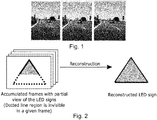
- the LED traffic lights as shown in pictures of Figure 1 actually flicker at the line frequency, for example 50 Hz.
- LED traffic lights are captured by camera or an image sensor with a refreshing rate at for instance 30 Hz, due to lack of time synchronization between the two, the LED lights appear to flicker, e.g. going on and off, partially or fully, as depicted in the consecutive frames of Figure 1 .
- An aspect of the present invention relates to a device for flicker removal by image analysis.
- the device comprises:
- the present device for flicker removal by image analysis fits very well in the traffic sign recognition, TSR, module by acting as a supplement to the detection stage of the TSR module.
- the present device for flicker removal by image analysis provides in a first stage a sign recognition module that is to detect the signs with a follow up tracking and classification.
- the present method can directly pass the reconstructed output obtained from the proposed LED reconstruction module to classification stage.
- a further, second aspect of the present invention relates to a method for flicker removal by image analysis, the method comprising the following steps of: identifying a portion of a LED traffic sign in at least one starting frame provided by an image sensor by means of a LED-region identifier; calculating a shape for a reconstructed LED sign based on the identified portion by means of a shape constructor; performing a color check of the reconstructed LED sign by means of a color verifier; and reconstructing the verified reconstructed LED sign of the at least one starting frame in at least one another frame provided by the image sensor by means of a frame reconstructor.
- the LED-region identifier is configured to identify the portion of the LED traffic sign by identifying rectangular areas and by performing color checking of the identified rectangular areas.
- the color verifier is configured to perform the color check of the reconstructed LED sign by performing a check for a black color.
- the shape constructor is configured to calculate the shape for the reconstructed LED sign based on template matching.
- the frame reconstructor is configured to reconstruct the verified reconstructed LED sign of the at least one starting frame in at least one another frame provided by the image sensor by projecting a position of the reconstructed LED sign in the at least one starting frame to a position of the reconstructed LED sign in the least one another frame.
- the frame reconstructor is configured to iteratively reconstruct the verified reconstructed LED sign in consecutive frames.
- a computer program performing the method of the present invention may be stored on a computer-readable medium.
- a computer-readable medium may be a floppy disk, a hard disk, a CD, a DVD, an USB (Universal Serial Bus) storage device, a RAM (Random Access Memory), a ROM (Read Only Memory) or an EPROM (Erasable Programmable Read Only Memory).
- a computer-readable medium may also be a data communication network, for example the Internet, which allows downloading a program code.
- DSP Digital Signal Processor
- ASIC application specific integrated circuit
- CPLD CPLD
- the present invention can be implemented in digital electronic circuitry or in computer hardware, firmware, software, or in combinations thereof, for instance in available hardware of conventional medical imaging devices or in new hardware dedicated for processing the methods described herein.
- Fig. 1 shows the sketch of LED traffic lights when flickering is present for explaining the present invention.
- Fig. 2 shows the proposed approach based according to an exemplary embodiment of the present invention.
- Fig. 2 shows an overview of the proposed method, in the left side of Fig. 2 , we have shown a portion of traffic sign which is visible in a frame. It is worthwhile to understand that same portion of the sign will not be visible in every frame. Therefore, various accumulated frames will have different visible portions of the sign.
- Fig. 3 shows another sketch of the schematic high level architecture chart according to an exemplary embodiment of the present invention.
- Fig. 3 shows the proposed system and sign recognition module and shows that the present method fits very well in the traffic Sign Recognition, TSR, module by acting as a supplement to the detection stage of the SR module.
- First stage in any classical sign recognition module is to detect the signs with a follow up tracking and classification. Since, the proposed system and sign recognition module is performing the shape detection and reconstruction, so we can directly pass the reconstructed output obtained from the proposed LED reconstruction module to classification stage.
- Fig. 3 illustrates a high level concept of the proposed solution.
- Our proposed system accepts accumulated cutout (Cutouts are defined as cropped out regions of images which are probably traffic signs) of the flickering LED regions and reconstructs it thereby yielding a quasi-full LED region.
- shape probability i.e. probability whether it is a circle, triangle etc.
- shape probability i.e. probability whether it is a circle, triangle etc.
- Length of the track here refers to the cardinality of a set; Entries in that set represents instances of the low prediction error of the tracker.
- Cutout will be accumulated only for the tracked LED regions, provided they fulfill low prediction error tolerance.
- the registration process may be performed as follows: Accumulated cutouts will have different spatial dimensions which makes the registration process complex. However, to circumvent this problem we can use the fact that accumulated cutouts belong to the same LED region and suffer from scaling effect. Scaling effect occurs when any vehicle approaches a sign; in that scenario LED traffic signs appear to be larger in spatial dimensions.
- Fig. 3 explains the algorithm for one object in the image only. Similar operation has to be performed for every object, found out in the image in order to utilize the LED reconstruction operation.
- EXIT in the Fig. 3 refers to the exit of the program.
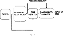
- Fig. 4 shows the proposed approach of the algorithm compatibility with sign recognition according to an exemplary embodiment of the present invention.
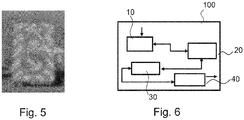
- Fig. 5 shows an example cutout according to an exemplary embodiment of the present invention.
- the example cutout may be extracted from a full frame.
- Fig. 6 shows a schematic diagram of the device for flicker removal by image analysis according to an exemplary embodiment of the present invention.
- the device 100 for flicker removal by image analysis comprises a LED-region identifier 10, a shape constructor 20, a color verifier 30, and a frame reconstructor 40.
- the LED-region identifier 10 is configured to identify a portion of a LED traffic sign in at least one starting frame provided by an image sensor.
- the shape constructor 20 is configured to calculate a shape for a reconstructed LED sign based on the identified portion.
- the color verifier 30 is configured to perform a color check of the reconstructed LED sign.
- the frame reconstructor 40 is configured to reconstruct the verified reconstructed LED sign of the at least one starting frame in at least one another frame provided by the image sensor.
- Fig. 7 shows a schematic diagram of the method for flicker removal by image analysis according to an exemplary embodiment of the present invention.
- the method for flicker removal by image analysis may comprise the following steps:
Landscapes
- Engineering & Computer Science (AREA)
- Physics & Mathematics (AREA)
- General Physics & Mathematics (AREA)
- Theoretical Computer Science (AREA)
- Computer Vision & Pattern Recognition (AREA)
- Multimedia (AREA)
- Image Analysis (AREA)
- Traffic Control Systems (AREA)
- Image Processing (AREA)
Abstract
a LED-region identifier (10), which is configured to identify a portion of a LED traffic sign in at least one starting frame provided by an image sensor; a shape constructor (20), which is configured to calculate a shape for a reconstructed LED sign based on the identified portion; a color verifier (30), which is configured to perform a color check of the reconstructed LED sign; and a frame reconstructor (40), which is configured to reconstruct the verified reconstructed LED sign of the at least one starting frame in at least one another frame provided by the image sensor.
Description
- The present invention relates to the field of object and traffic sign recognition. Particularly, the present invention relates to a device and a method for flicker removal by image analysis.
- Sign recognition project aims at detecting and classifying the traffic signs occurring on the road sides. Currently, LED traffic signs are often only partially depicted. The LED traffic lights as shown in pictures of
Figure 1 actually flicker at the line frequency, for example 50 Hz. - When these LED traffic lights are captured by camera or an image sensor with a refreshing rate at for
instance 30 Hz, due to lack of time synchronization between the two, the LED lights appear to flicker, e.g. going on and off, partially or fully, as depicted in the consecutive frames ofFigure 1 . - Hence any further traffic sign recognizer, TSR, would fail as a wrong shape would be provided.
- There may be a need to improve device and methods for flicker removal by image analysis of traffic signs for a vehicle.
- These needs are met by the subject-matter of the independent claims. Further exemplary embodiments are evident from the dependent claims and the following description.
- An aspect of the present invention relates to a device for flicker removal by image analysis. The device comprises:
- a LED-region identifier, which is configured to identify a portion of a LED traffic sign in at least one starting frame provided by an image sensor; the device further comprises a shape constructor, which is configured to calculate a shape for a reconstructed LED sign based on the identified portion;
- the device further comprises a color verifier, which is configured to perform a color check of the reconstructed LED sign; and the device further comprises a frame reconstructor, which is configured to reconstruct the verified reconstructed LED sign of the at least one starting frame in at least one another frame provided by the image sensor.
- The present device for flicker removal by image analysis fits very well in the traffic sign recognition, TSR, module by acting as a supplement to the detection stage of the TSR module.
- The present device for flicker removal by image analysis provides in a first stage a sign recognition module that is to detect the signs with a follow up tracking and classification.
- Since, the performing of the shape detection and reconstruction is performed independently, the present method can directly pass the reconstructed output obtained from the proposed LED reconstruction module to classification stage.
- A further, second aspect of the present invention relates to a method for flicker removal by image analysis, the method comprising the following steps of: identifying a portion of a LED traffic sign in at least one starting frame provided by an image sensor by means of a LED-region identifier; calculating a shape for a reconstructed LED sign based on the identified portion by means of a shape constructor; performing a color check of the reconstructed LED sign by means of a color verifier; and reconstructing the verified reconstructed LED sign of the at least one starting frame in at least one another frame provided by the image sensor by means of a frame reconstructor.
- According to an exemplary embodiment of the present invention, the LED-region identifier is configured to identify the portion of the LED traffic sign by identifying rectangular areas and by performing color checking of the identified rectangular areas.
- According to an exemplary embodiment of the present invention, the color verifier is configured to perform the color check of the reconstructed LED sign by performing a check for a black color.
- According to an exemplary embodiment of the present invention, the shape constructor is configured to calculate the shape for the reconstructed LED sign based on template matching.
- According to an exemplary embodiment of the present invention, the frame reconstructor is configured to reconstruct the verified reconstructed LED sign of the at least one starting frame in at least one another frame provided by the image sensor by projecting a position of the reconstructed LED sign in the at least one starting frame to a position of the reconstructed LED sign in the least one another frame.
- According to an exemplary embodiment of the present invention, the frame reconstructor is configured to iteratively reconstruct the verified reconstructed LED sign in consecutive frames.
- A computer program performing the method of the present invention may be stored on a computer-readable medium. A computer-readable medium may be a floppy disk, a hard disk, a CD, a DVD, an USB (Universal Serial Bus) storage device, a RAM (Random Access Memory), a ROM (Read Only Memory) or an EPROM (Erasable Programmable Read Only Memory).
- A computer-readable medium may also be a data communication network, for example the Internet, which allows downloading a program code.
- The methods, systems, and devices described herein may be implemented as software in a Digital Signal Processor, DSP, in a micro-controller or in any other side-processor or as a hardware circuit within an application specific integrated circuit, ASIC, CPLD or FPGA.
- The present invention can be implemented in digital electronic circuitry or in computer hardware, firmware, software, or in combinations thereof, for instance in available hardware of conventional medical imaging devices or in new hardware dedicated for processing the methods described herein.
- A more complete appreciation of the invention and the attendant advantages thereof will be clearly understood by reference to the following schematic drawings, which are not to scale, wherein:
- Fig. 1
- shows the sketch of LED traffic lights when flickering is present for explaining the present invention;
- Fig. 2
- shows the proposed approach based according to an exemplary embodiment of the present invention;
- Fig. 3
- shows another sketch of the schematic high level architecture chart according to an exemplary embodiment of the present invention;
- Fig. 4
- shows the proposed approach of the algorithm compatibility with sign recognition according to an exemplary embodiment of the present invention;
- Fig. 5
- shows an example cutout according to an exemplary embodiment of the present invention;
- Fig. 6
- shows a schematic diagram of the device for flicker removal by image analysis according to an exemplary embodiment of the present invention; and
- Fig. 7
- shows another sketch of the method for flicker removal by image analysis according to an exemplary embodiment of the present invention.
- The illustration in the drawings is purely schematic and does not intend to provide scaling relations or size information. In different drawings, similar or identical elements are provided with the same reference numerals.
- Generally, identical parts, units, entities or steps are provided with the same reference symbols in the description.
-
Fig. 1 shows the sketch of LED traffic lights when flickering is present for explaining the present invention. -
Fig. 2 shows the proposed approach based according to an exemplary embodiment of the present invention. -
Fig. 2 shows an overview of the proposed method, in the left side ofFig. 2 , we have shown a portion of traffic sign which is visible in a frame. It is worthwhile to understand that same portion of the sign will not be visible in every frame. Therefore, various accumulated frames will have different visible portions of the sign. -
Fig. 3 shows another sketch of the schematic high level architecture chart according to an exemplary embodiment of the present invention. -
Fig. 3 shows the proposed system and sign recognition module and shows that the present method fits very well in the traffic Sign Recognition, TSR, module by acting as a supplement to the detection stage of the SR module. - First stage in any classical sign recognition module is to detect the signs with a follow up tracking and classification. Since, the proposed system and sign recognition module is performing the shape detection and reconstruction, so we can directly pass the reconstructed output obtained from the proposed LED reconstruction module to classification stage.
-
Fig. 3 illustrates a high level concept of the proposed solution. Our proposed system accepts accumulated cutout (Cutouts are defined as cropped out regions of images which are probably traffic signs) of the flickering LED regions and reconstructs it thereby yielding a quasi-full LED region. - It is to be noted in
Fig. 3 that accumulated cutouts will exhibit non-overlapping shapes over various frames.Fig. 2 should not be understood as if same piece of shape will reappear in every frame. - The algorithm has been shown in
Fig. 3 . Since, the problem at hand is to reconstruct the flickering LED signs therefore our algorithm starts with finding the potential LED regions in any image frame. LED cutouts can be detected in any image frame by finding out the rectangles (mostly LED signs have black background) and then performing a color check on it. - Once the LED region is found out then we compute shape probability i.e. probability whether it is a circle, triangle etc. Such operation can be achieved by using template matching approach.
- However, to reduce false positive we perform a color check corresponding to the computed shape. If the color check is passed, then we initiate one track, for instance for the rectangle region containing LED sign, which is tracked across frames with the help of Kalman filter. If the LED region is a real sign, then we will get low error in between the projected position and the actual position of the sign, in the next frame.
- It is to be noted here that projected position of the LED region has been computed in (n-1)-th frame by the tracker and the actual position of the LED sign has been measured in the n-th frame. Such low temporal error signifies that the current LED region is a real sign. On the other hand, if we get large error then it signifies that we are tracking a false object and then the corresponding track is killed.
- If the length of the track is more than 1 then we accumulate those cutout regions in the local memory. Length of the track here refers to the cardinality of a set; Entries in that set represents instances of the low prediction error of the tracker.
- Cutout will be accumulated only for the tracked LED regions, provided they fulfill low prediction error tolerance.
- Once, we have accumulated the cutouts, we try to reconstruct the shape of the accumulated cutouts so that it can be fed to TSA module for classification purpose. For that purpose, we perform various operations i.e. (1) resize all the cutouts to same size based on the shape reconstruction (2) contrast enhancement (3) Perform affine transform (while considering scaling and rotation effects) on the basis of reconstructed shape, (4) Align the cutouts, and (5) Register the images.
- The registration process may be performed as follows: Accumulated cutouts will have different spatial dimensions which makes the registration process complex. However, to circumvent this problem we can use the fact that accumulated cutouts belong to the same LED region and suffer from scaling effect. Scaling effect occurs when any vehicle approaches a sign; in that scenario LED traffic signs appear to be larger in spatial dimensions.
- According to an exemplary embodiment of the present invention, we scale all the cutouts to same spatial dimension. After scaling to same resolution, we average all the pixel values in order to obtain the reconstructed image.
- We may start this reconstruction process with k cutouts (k = 2 for first instance). After reconstruction we perform a color check to confirm that it is a valid LED sign. This color check ensures that we are passing a valid LED region for the classification.
- We may pass the reconstructed LED sign to the TSA classifier; if the TSA classifier outputs garbage class for reconstructed sign (with k = 2) then we increment k and again reconstruct with k = k+1. However, to limit the time complexity of the algorithm, k cannot be more than N = 7.
-
Fig. 3 explains the algorithm for one object in the image only. Similar operation has to be performed for every object, found out in the image in order to utilize the LED reconstruction operation. - EXIT, in the
Fig. 3 refers to the exit of the program. -
Fig. 4 shows the proposed approach of the algorithm compatibility with sign recognition according to an exemplary embodiment of the present invention. -
Fig. 5 shows an example cutout according to an exemplary embodiment of the present invention. - The example cutout may be extracted from a full frame.
-
Fig. 6 shows a schematic diagram of the device for flicker removal by image analysis according to an exemplary embodiment of the present invention. - The
device 100 for flicker removal by image analysis, comprises a LED-region identifier 10, ashape constructor 20, acolor verifier 30, and aframe reconstructor 40. - The LED-
region identifier 10 is configured to identify a portion of a LED traffic sign in at least one starting frame provided by an image sensor. - The
shape constructor 20 is configured to calculate a shape for a reconstructed LED sign based on the identified portion. - The
color verifier 30 is configured to perform a color check of the reconstructed LED sign. - The
frame reconstructor 40 is configured to reconstruct the verified reconstructed LED sign of the at least one starting frame in at least one another frame provided by the image sensor. -
Fig. 7 shows a schematic diagram of the method for flicker removal by image analysis according to an exemplary embodiment of the present invention. - The method for flicker removal by image analysis, may comprise the following steps:
- As a first step of the method, identifying S1 a portion of a LED traffic sign in at least one starting frame provided by an image sensor by means of a LED-
region identifier 10 may be performed. - As a second step of the method, calculating S2 a shape for a reconstructed LED sign based on the identified portion by means of a
shape constructor 20 may be performed. - As a third step of the method, performing S3 a color check of the reconstructed LED sign by means of a
color verifier 30 is conducted. - As a fourth step of the method, reconstructing S4 the verified reconstructed LED sign of the at least one starting frame in at least one another frame provided by the image sensor by means of a
frame reconstructor 40 is conducted. - It has to be noted that embodiments of the present invention are described with reference to different subject-matters. In particular, some embodiments are described with reference to method type claims, whereas other embodiments are described with reference to the device type claims.
- However, a person skilled in the art will gather from the above and the foregoing description that, unless otherwise notified, in addition to any combination of features belonging to one type of the subject-matter also any combination between features relating to different subject-matters is considered to be disclosed with this application.
- However, all features can be combined providing synergetic effects that are more than the simple summation of these features.
- While the invention has been illustrated and described in detail in the drawings and foregoing description, such illustration and description are to be considered illustrative or exemplary and not restrictive; the present invention is not limited to the disclosed embodiments.
- Other variations to the disclosed embodiments can be understood and effected by those skilled in the art and practicing the claimed invention, from a study of the drawings, the disclosure, and the appended claims.
- In the claims, the word "comprising" does not exclude other elements or steps, and the indefinite article "a" or "an" does not exclude a plurality. A single processor or controller or other unit may fulfill the functions of several items recited in the claims.
- The mere fact that certain measures are recited in mutually different dependent claims does not indicate that a combination of these measures cannot be used to advantage. Any reference signs in the claims should not be considered as limiting the scope.
Claims (8)
- Device (100) for flicker removal by Image analysis, the device (100) comprising:- a LED-region identifier (10), which is configured to identify a portion of a LED-sign in at least one starting frame provided by an image sensor;- a shape constructor (20), which is configured to calculate a shape for a reconstructed LED sign based on the identified portion;- a color verifier (30), which is configured to perform a color check of the reconstructed LED sign; and- a flickering LED sign reconstructor (40), which is configured to reconstruct the verified reconstructed LED sign of the at least one starting frame in at least one another frame provided by the image sensor.
- The device (100) according to claim 1,
wherein the LED-region identifier (10) is configured to identify the portion of the LED-sign by identifying area of preknown geometry such as Rectangle and by performing color checking of the identified rectangular areas. - The device according to claim 1 or 2,
wherein the shape constructor (20) is configured to calculate the shape for the reconstructed LED sign based on template matching. - The device according to any one of the preceding claims,
wherein the color verifier (30) is configured to perform the color check of the reconstructed LED-sign by performing a background color check for a background of a predefined color. - The device according to claim 4, wherein the color verifier (30) is configured to perform the color check of the reconstructed LED-sign by performing the background color check for interested geometry regions containing LED signs and then tracking it using a tracker.
- The device according to any one of the preceding claims,
wherein the frame reconstructor (40) is configured to reconstruct the verified reconstructed LED sign of the at least one starting frame in at least one another frame provided by the image sensor by projecting a position of the reconstructed LED sign in the at least one starting frame to a position of the reconstructed LED sign in the least one another frame. - The device according to claim 6,
wherein the frame reconstructor (40) is configured to iteratively reconstruct the verified reconstructed LED sign in consecutive frames. - A method for flicker removal by image analysis, the method comprising the following steps of:- identifying (S1) a portion of a LED traffic sign in at least one starting frame provided by an image sensor by means of a LED-region identifier (10);- calculating (S2) a shape for a reconstructed LED sign based on the identified portion by means of a shape constructor (20);- performing (S3) a color check of the reconstructed LED sign by means of a color verifier (30); and- reconstructing (S4) the verified reconstructed LED sign of the at least one starting frame in at least one another frame provided by the image sensor by means of a frame reconstructor (40).
Priority Applications (3)
| Application Number | Priority Date | Filing Date | Title |
|---|---|---|---|
| EP17153502.4A EP3355238B1 (en) | 2017-01-27 | 2017-01-27 | Device and method for flicker removal by image analysis |
| KR1020180008327A KR102526217B1 (en) | 2017-01-27 | 2018-01-23 | Device and method for flicker removal by image analysis |
| JP2018011432A JP7208712B2 (en) | 2017-01-27 | 2018-01-26 | Apparatus and method for deblinking by image analysis |
Applications Claiming Priority (1)
| Application Number | Priority Date | Filing Date | Title |
|---|---|---|---|
| EP17153502.4A EP3355238B1 (en) | 2017-01-27 | 2017-01-27 | Device and method for flicker removal by image analysis |
Publications (2)
| Publication Number | Publication Date |
|---|---|
| EP3355238A1 true EP3355238A1 (en) | 2018-08-01 |
| EP3355238B1 EP3355238B1 (en) | 2026-03-11 |
Family
ID=57914830
Family Applications (1)
| Application Number | Title | Priority Date | Filing Date |
|---|---|---|---|
| EP17153502.4A Active EP3355238B1 (en) | 2017-01-27 | 2017-01-27 | Device and method for flicker removal by image analysis |
Country Status (3)
| Country | Link |
|---|---|
| EP (1) | EP3355238B1 (en) |
| JP (1) | JP7208712B2 (en) |
| KR (1) | KR102526217B1 (en) |
Family Cites Families (5)
| Publication number | Priority date | Publication date | Assignee | Title |
|---|---|---|---|---|
| KR100676847B1 (en) * | 2004-03-27 | 2007-02-05 | 종 해 김 | Reflective LED Road Sign Bottle System |
| KR100885402B1 (en) * | 2007-08-14 | 2009-02-24 | 종 해 김 | Versatile LED Traffic Light Systems and Devices |
| KR100935634B1 (en) | 2009-06-30 | 2010-01-07 | (주) 에스엘테크 | Road sign using optical fiber |
| WO2013113421A1 (en) * | 2012-02-03 | 2013-08-08 | Continental Teves Ag & Co. Ohg | Signal generator, system and method for highlighting objects in road traffic, use of the system, and use of the signal generator |
| JP2014153167A (en) | 2013-02-07 | 2014-08-25 | Nidec Elesys Corp | Object recognition device, object recognition method, and object recognition program |
-
2017
- 2017-01-27 EP EP17153502.4A patent/EP3355238B1/en active Active
-
2018
- 2018-01-23 KR KR1020180008327A patent/KR102526217B1/en active Active
- 2018-01-26 JP JP2018011432A patent/JP7208712B2/en active Active
Non-Patent Citations (2)
| Title |
|---|
| "Master Thesis", 2 September 2010, article HASAN IRMAK: "REAL TIME TRAFFIC SIGN RECOGNITION SYSTEM ON FPGA-Chapters 2 and 3", XP055382694 * |
| KOTARO NAKAZAWA ET AL: "Flicker and black-streak artifact removal from images of display monitors taken by video cameras", SIGNAL&INFORMATION PROCESSING ASSOCIATION ANNUAL SUMMIT AND CONFERENCE (APSIPA ASC), 2012 ASIA-PACIFIC, IEEE, 3 December 2012 (2012-12-03), pages 1 - 4, XP032309840, ISBN: 978-1-4673-4863-8 * |
Also Published As
| Publication number | Publication date |
|---|---|
| KR20180088587A (en) | 2018-08-06 |
| KR102526217B1 (en) | 2023-04-26 |
| JP2018136932A (en) | 2018-08-30 |
| EP3355238B1 (en) | 2026-03-11 |
| JP7208712B2 (en) | 2023-01-19 |
Similar Documents
| Publication | Publication Date | Title |
|---|---|---|
| CN111476234B (en) | A method, device, storage medium and intelligent device for recognizing characters on an obscured license plate | |
| US10984252B2 (en) | Apparatus and method for analyzing people flows in image | |
| US11600008B2 (en) | Human-tracking methods, systems, and storage media | |
| US8811663B2 (en) | Object detection in crowded scenes | |
| US8983131B2 (en) | Video analysis | |
| US10068146B2 (en) | Method and system for detection-based segmentation-free license plate recognition | |
| US10169661B2 (en) | Filtering methods for visual object detection | |
| WO2009049314A2 (en) | Video processing system employing behavior subtraction between reference and observed video image sequences | |
| US20130265421A1 (en) | System and method for object detection | |
| JP2008542922A (en) | Human detection and tracking for security applications | |
| Bosch-Jorge et al. | Fall detection based on the gravity vector using a wide-angle camera | |
| KR20120020008A (en) | Method for reconstructing super-resolution image, and system for detecting illegally parked vehicles therewith | |
| US10303952B2 (en) | Method of detecting a moving object by reconstructive image processing | |
| El Shair et al. | High-temporal-resolution event-based vehicle detection and tracking | |
| CN104573680A (en) | Image detection method, image detection device and traffic violation detection system | |
| CN111950501B (en) | Obstacle detection method and device and electronic equipment | |
| CN114332720B (en) | Camera device occlusion detection method, device, electronic equipment and storage medium | |
| Boufares et al. | Moving object detection system based on the modified temporal difference and otsu algorithm | |
| CN113191293B (en) | Advertisement detection method, device, electronic equipment, system and readable storage medium | |
| EP3355238B1 (en) | Device and method for flicker removal by image analysis | |
| CN114998929A (en) | Fisheye camera bounding box identification method, fisheye camera bounding box identification system, fisheye camera bounding box identification equipment and application | |
| JP6527183B2 (en) | Leftover object detection device | |
| Lee et al. | Real-time detection of illegally parked vehicles using 1-D transformation | |
| CN111950502A (en) | Obstacle object-based detection method and device and computer equipment | |
| Shukla et al. | An Algorithmic Approach for Real Time People Counting with Moving Background |
Legal Events
| Date | Code | Title | Description |
|---|---|---|---|
| PUAI | Public reference made under article 153(3) epc to a published international application that has entered the european phase |
Free format text: ORIGINAL CODE: 0009012 |
|
| STAA | Information on the status of an ep patent application or granted ep patent |
Free format text: STATUS: THE APPLICATION HAS BEEN PUBLISHED |
|
| AK | Designated contracting states |
Kind code of ref document: A1 Designated state(s): AL AT BE BG CH CY CZ DE DK EE ES FI FR GB GR HR HU IE IS IT LI LT LU LV MC MK MT NL NO PL PT RO RS SE SI SK SM TR |
|
| AX | Request for extension of the european patent |
Extension state: BA ME |
|
| STAA | Information on the status of an ep patent application or granted ep patent |
Free format text: STATUS: REQUEST FOR EXAMINATION WAS MADE |
|
| 17P | Request for examination filed |
Effective date: 20190201 |
|
| RBV | Designated contracting states (corrected) |
Designated state(s): AL AT BE BG CH CY CZ DE DK EE ES FI FR GB GR HR HU IE IS IT LI LT LU LV MC MK MT NL NO PL PT RO RS SE SI SK SM TR |
|
| RAP1 | Party data changed (applicant data changed or rights of an application transferred) |
Owner name: CONTINENTAL AUTOMOTIVE GMBH |
|
| STAA | Information on the status of an ep patent application or granted ep patent |
Free format text: STATUS: EXAMINATION IS IN PROGRESS |
|
| 17Q | First examination report despatched |
Effective date: 20210504 |
|
| RAP1 | Party data changed (applicant data changed or rights of an application transferred) |
Owner name: CONTINENTAL AUTONOMOUS MOBILITY GERMANY GMBH |
|
| RAP3 | Party data changed (applicant data changed or rights of an application transferred) |
Owner name: AUMOVIO AUTONOMOUS MOBILITY GERMANY GMBH |
|
| REG | Reference to a national code |
Ref country code: DE Ref legal event code: R079 Free format text: PREVIOUS MAIN CLASS: G06K0009000000 Ipc: G06V0020580000 Ref country code: DE Ref legal event code: R079 Ref document number: 602017094232 Country of ref document: DE Free format text: PREVIOUS MAIN CLASS: G06K0009000000 Ipc: G06V0020580000 |
|
| GRAP | Despatch of communication of intention to grant a patent |
Free format text: ORIGINAL CODE: EPIDOSNIGR1 |
|
| STAA | Information on the status of an ep patent application or granted ep patent |
Free format text: STATUS: GRANT OF PATENT IS INTENDED |
|
| RIC1 | Information provided on ipc code assigned before grant |
Ipc: G06V 20/58 20220101AFI20250924BHEP |
|
| INTG | Intention to grant announced |
Effective date: 20251010 |
|
| GRAS | Grant fee paid |
Free format text: ORIGINAL CODE: EPIDOSNIGR3 |
|
| GRAA | (expected) grant |
Free format text: ORIGINAL CODE: 0009210 |
|
| STAA | Information on the status of an ep patent application or granted ep patent |
Free format text: STATUS: THE PATENT HAS BEEN GRANTED |
|
| AK | Designated contracting states |
Kind code of ref document: B1 Designated state(s): AL AT BE BG CH CY CZ DE DK EE ES FI FR GB GR HR HU IE IS IT LI LT LU LV MC MK MT NL NO PL PT RO RS SE SI SK SM TR |
|
| REG | Reference to a national code |
Ref country code: CH Ref legal event code: F10 Free format text: ST27 STATUS EVENT CODE: U-0-0-F10-F00 (AS PROVIDED BY THE NATIONAL OFFICE) Effective date: 20260311 Ref country code: GB Ref legal event code: FG4D |
|
| REG | Reference to a national code |
Ref country code: DE Ref legal event code: R083 Ref document number: 602017094232 Country of ref document: DE |
|
| REG | Reference to a national code |
Ref country code: DE Ref legal event code: R096 Ref document number: 602017094232 Country of ref document: DE |
|
| REG | Reference to a national code |
Ref country code: IE Ref legal event code: FG4D |
|
| PG25 | Lapsed in a contracting state [announced via postgrant information from national office to epo] |
Ref country code: RS Free format text: LAPSE BECAUSE OF FAILURE TO SUBMIT A TRANSLATION OF THE DESCRIPTION OR TO PAY THE FEE WITHIN THE PRESCRIBED TIME-LIMIT Effective date: 20260611 |
|
| PG25 | Lapsed in a contracting state [announced via postgrant information from national office to epo] |
Ref country code: ES Free format text: LAPSE BECAUSE OF FAILURE TO SUBMIT A TRANSLATION OF THE DESCRIPTION OR TO PAY THE FEE WITHIN THE PRESCRIBED TIME-LIMIT Effective date: 20260311 |
|
| PG25 | Lapsed in a contracting state [announced via postgrant information from national office to epo] |
Ref country code: GR Free format text: LAPSE BECAUSE OF FAILURE TO SUBMIT A TRANSLATION OF THE DESCRIPTION OR TO PAY THE FEE WITHIN THE PRESCRIBED TIME-LIMIT Effective date: 20260612 |
|
| REG | Reference to a national code |
Ref country code: LT Ref legal event code: MG9D |
|
| PG25 | Lapsed in a contracting state [announced via postgrant information from national office to epo] |
Ref country code: LT Free format text: LAPSE BECAUSE OF FAILURE TO SUBMIT A TRANSLATION OF THE DESCRIPTION OR TO PAY THE FEE WITHIN THE PRESCRIBED TIME-LIMIT Effective date: 20260311 |
|
| PG25 | Lapsed in a contracting state [announced via postgrant information from national office to epo] |
Ref country code: NO Free format text: LAPSE BECAUSE OF FAILURE TO SUBMIT A TRANSLATION OF THE DESCRIPTION OR TO PAY THE FEE WITHIN THE PRESCRIBED TIME-LIMIT Effective date: 20260611 |
|
| PG25 | Lapsed in a contracting state [announced via postgrant information from national office to epo] |
Ref country code: FI Free format text: LAPSE BECAUSE OF FAILURE TO SUBMIT A TRANSLATION OF THE DESCRIPTION OR TO PAY THE FEE WITHIN THE PRESCRIBED TIME-LIMIT Effective date: 20260311 Ref country code: SE Free format text: LAPSE BECAUSE OF FAILURE TO SUBMIT A TRANSLATION OF THE DESCRIPTION OR TO PAY THE FEE WITHIN THE PRESCRIBED TIME-LIMIT Effective date: 20260311 |
|
| REG | Reference to a national code |
Ref country code: NL Ref legal event code: MP Effective date: 20260311 |
|
| PG25 | Lapsed in a contracting state [announced via postgrant information from national office to epo] |
Ref country code: HR Free format text: LAPSE BECAUSE OF FAILURE TO SUBMIT A TRANSLATION OF THE DESCRIPTION OR TO PAY THE FEE WITHIN THE PRESCRIBED TIME-LIMIT Effective date: 20260311 |
|
| PG25 | Lapsed in a contracting state [announced via postgrant information from national office to epo] |
Ref country code: LV Free format text: LAPSE BECAUSE OF FAILURE TO SUBMIT A TRANSLATION OF THE DESCRIPTION OR TO PAY THE FEE WITHIN THE PRESCRIBED TIME-LIMIT Effective date: 20260311 |
|
| PG25 | Lapsed in a contracting state [announced via postgrant information from national office to epo] |
Ref country code: BG Free format text: LAPSE BECAUSE OF FAILURE TO SUBMIT A TRANSLATION OF THE DESCRIPTION OR TO PAY THE FEE WITHIN THE PRESCRIBED TIME-LIMIT Effective date: 20260311 |