EP3355129A1 - Developing device, process cartridge, and image forming apparatus - Google Patents
Developing device, process cartridge, and image forming apparatus Download PDFInfo
- Publication number
- EP3355129A1 EP3355129A1 EP18152917.3A EP18152917A EP3355129A1 EP 3355129 A1 EP3355129 A1 EP 3355129A1 EP 18152917 A EP18152917 A EP 18152917A EP 3355129 A1 EP3355129 A1 EP 3355129A1
- Authority
- EP
- European Patent Office
- Prior art keywords
- developing
- main body
- image forming
- forming apparatus
- apparatus main
- Prior art date
- Legal status (The legal status is an assumption and is not a legal conclusion. Google has not performed a legal analysis and makes no representation as to the accuracy of the status listed.)
- Granted
Links
Images







Classifications
-
- G—PHYSICS
- G03—PHOTOGRAPHY; CINEMATOGRAPHY; ANALOGOUS TECHNIQUES USING WAVES OTHER THAN OPTICAL WAVES; ELECTROGRAPHY; HOLOGRAPHY
- G03G—ELECTROGRAPHY; ELECTROPHOTOGRAPHY; MAGNETOGRAPHY
- G03G21/00—Arrangements not provided for by groups G03G13/00 - G03G19/00, e.g. cleaning, elimination of residual charge
- G03G21/16—Mechanical means for facilitating the maintenance of the apparatus, e.g. modular arrangements
- G03G21/1642—Mechanical means for facilitating the maintenance of the apparatus, e.g. modular arrangements for connecting the different parts of the apparatus
- G03G21/1652—Electrical connection means
-
- G—PHYSICS
- G03—PHOTOGRAPHY; CINEMATOGRAPHY; ANALOGOUS TECHNIQUES USING WAVES OTHER THAN OPTICAL WAVES; ELECTROGRAPHY; HOLOGRAPHY
- G03G—ELECTROGRAPHY; ELECTROPHOTOGRAPHY; MAGNETOGRAPHY
- G03G21/00—Arrangements not provided for by groups G03G13/00 - G03G19/00, e.g. cleaning, elimination of residual charge
- G03G21/16—Mechanical means for facilitating the maintenance of the apparatus, e.g. modular arrangements
- G03G21/18—Mechanical means for facilitating the maintenance of the apparatus, e.g. modular arrangements using a processing cartridge, whereby the process cartridge comprises at least two image processing means in a single unit
- G03G21/1803—Arrangements or disposition of the complete process cartridge or parts thereof
- G03G21/1817—Arrangements or disposition of the complete process cartridge or parts thereof having a submodular arrangement
- G03G21/1825—Pivotable subunit connection
-
- G—PHYSICS
- G03—PHOTOGRAPHY; CINEMATOGRAPHY; ANALOGOUS TECHNIQUES USING WAVES OTHER THAN OPTICAL WAVES; ELECTROGRAPHY; HOLOGRAPHY
- G03G—ELECTROGRAPHY; ELECTROPHOTOGRAPHY; MAGNETOGRAPHY
- G03G15/00—Apparatus for electrographic processes using a charge pattern
- G03G15/06—Apparatus for electrographic processes using a charge pattern for developing
- G03G15/08—Apparatus for electrographic processes using a charge pattern for developing using a solid developer, e.g. powder developer
- G03G15/0806—Apparatus for electrographic processes using a charge pattern for developing using a solid developer, e.g. powder developer on a donor element, e.g. belt, roller
-
- G—PHYSICS
- G03—PHOTOGRAPHY; CINEMATOGRAPHY; ANALOGOUS TECHNIQUES USING WAVES OTHER THAN OPTICAL WAVES; ELECTROGRAPHY; HOLOGRAPHY
- G03G—ELECTROGRAPHY; ELECTROPHOTOGRAPHY; MAGNETOGRAPHY
- G03G15/00—Apparatus for electrographic processes using a charge pattern
- G03G15/06—Apparatus for electrographic processes using a charge pattern for developing
- G03G15/08—Apparatus for electrographic processes using a charge pattern for developing using a solid developer, e.g. powder developer
- G03G15/0896—Arrangements or disposition of the complete developer unit or parts thereof not provided for by groups G03G15/08 - G03G15/0894
-
- G—PHYSICS
- G03—PHOTOGRAPHY; CINEMATOGRAPHY; ANALOGOUS TECHNIQUES USING WAVES OTHER THAN OPTICAL WAVES; ELECTROGRAPHY; HOLOGRAPHY
- G03G—ELECTROGRAPHY; ELECTROPHOTOGRAPHY; MAGNETOGRAPHY
- G03G15/00—Apparatus for electrographic processes using a charge pattern
- G03G15/80—Details relating to power supplies, circuits boards, electrical connections
-
- G—PHYSICS
- G03—PHOTOGRAPHY; CINEMATOGRAPHY; ANALOGOUS TECHNIQUES USING WAVES OTHER THAN OPTICAL WAVES; ELECTROGRAPHY; HOLOGRAPHY
- G03G—ELECTROGRAPHY; ELECTROPHOTOGRAPHY; MAGNETOGRAPHY
- G03G21/00—Arrangements not provided for by groups G03G13/00 - G03G19/00, e.g. cleaning, elimination of residual charge
- G03G21/16—Mechanical means for facilitating the maintenance of the apparatus, e.g. modular arrangements
- G03G21/18—Mechanical means for facilitating the maintenance of the apparatus, e.g. modular arrangements using a processing cartridge, whereby the process cartridge comprises at least two image processing means in a single unit
- G03G21/1803—Arrangements or disposition of the complete process cartridge or parts thereof
- G03G21/1814—Details of parts of process cartridge, e.g. for charging, transfer, cleaning, developing
-
- G—PHYSICS
- G03—PHOTOGRAPHY; CINEMATOGRAPHY; ANALOGOUS TECHNIQUES USING WAVES OTHER THAN OPTICAL WAVES; ELECTROGRAPHY; HOLOGRAPHY
- G03G—ELECTROGRAPHY; ELECTROPHOTOGRAPHY; MAGNETOGRAPHY
- G03G21/00—Arrangements not provided for by groups G03G13/00 - G03G19/00, e.g. cleaning, elimination of residual charge
- G03G21/16—Mechanical means for facilitating the maintenance of the apparatus, e.g. modular arrangements
- G03G21/18—Mechanical means for facilitating the maintenance of the apparatus, e.g. modular arrangements using a processing cartridge, whereby the process cartridge comprises at least two image processing means in a single unit
- G03G21/1839—Means for handling the process cartridge in the apparatus body
- G03G21/1842—Means for handling the process cartridge in the apparatus body for guiding and mounting the process cartridge, positioning, alignment, locks
- G03G21/185—Means for handling the process cartridge in the apparatus body for guiding and mounting the process cartridge, positioning, alignment, locks the process cartridge being mounted parallel to the axis of the photosensitive member
-
- G—PHYSICS
- G03—PHOTOGRAPHY; CINEMATOGRAPHY; ANALOGOUS TECHNIQUES USING WAVES OTHER THAN OPTICAL WAVES; ELECTROGRAPHY; HOLOGRAPHY
- G03G—ELECTROGRAPHY; ELECTROPHOTOGRAPHY; MAGNETOGRAPHY
- G03G21/00—Arrangements not provided for by groups G03G13/00 - G03G19/00, e.g. cleaning, elimination of residual charge
- G03G21/16—Mechanical means for facilitating the maintenance of the apparatus, e.g. modular arrangements
- G03G21/18—Mechanical means for facilitating the maintenance of the apparatus, e.g. modular arrangements using a processing cartridge, whereby the process cartridge comprises at least two image processing means in a single unit
- G03G21/1839—Means for handling the process cartridge in the apparatus body
- G03G21/1867—Means for handling the process cartridge in the apparatus body for electrically connecting the process cartridge to the apparatus, electrical connectors, power supply
Definitions
- the present invention relates to a developing device, a process cartridge, and an image forming apparatus, and is particularly suitable for an image forming apparatus using an electrophotographic image forming process.
- image forming apparatuses include printers (laser beam printers, light-emitting diode (LED) printers, and so forth), copiers, facsimile devices, word processes, multifunctional apparatuses thereof (multifunction printers), and so forth.
- a photosensitive drum and processing means that act upon the photosensitive drum are fully or partly integrated into a cartridge.
- a process cartridge system where this cartridge is detachably mountable to the main body of the image forming apparatus, is employed. According to this process cartridge system, users can perform maintenance of the image forming apparatus by exchanging process cartridges and developing devices, thereby markedly improving operability.
- this process cartridge system is in widespread use in electrophotographic image forming apparatuses.
- One of process means acting upon the photosensitive drum is a developing roller that develops developer contained in the cartridge.
- This developing roller comes into contact with the photosensitive drum, thereby developing an electrostatic latent image formed on the photosensitive drum.
- this developing roller remains in contact with the photosensitive drum for prolonged periods of time, the developing roller deforms, which affects image quality. Accordingly, a configuration is made where the developing roller comes into contact with the photosensitive drum only when forming images, and at other times is separated from the photosensitive drum, to suppress deformation of the developing roller.
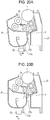
- FIG. 20A is a cross-sectional view of a process cartridge where a developing roller 25 is separated from a photosensitive drum 1.
- a shaft is inserted through a hole, omitted from illustration, that is provided in a developing frame 31, and a hole 27b provided in a cleaning frame 27, with the developing frame 31 being rotatably supported by the cleaning frame 27 with the shaft as a pivot center Y.
- a pressing member 32 provided to the image forming apparatus comes into contact with a pressed face 31e of the developing frame 31, whereby the developing roller 25 is urged in the direction of the arrow G, centered on the pivot center Y, and a state of separation from the photosensitive drum 1 is maintained.
- Fig. 20B is a cross-sectional view of the process cartridge when the developing roller 25 is in contact with the photosensitive drum 1.
- the pressing member 32 moves in the direction of the arrow H
- the developing frame 31 rotates in the direction of the arrow C, centered on the pivot center Y, under elastic force of a spring (omitted from illustration) provided to the developing frame 31.
- the developing roller 25 then comes into contact with the photosensitive drum 1, and further remains in contact with the photosensitive drum 1 at a predetermined pressure, by the elastic force of the spring.
- the pivot center of the developing frame has been provided at one end side in a particular direction in a cross-section of the developing frame orthogonal to the longitudinal direction (the direction in which the shaft extends) of the process cartridge, in the conventional contact/separation configuration of the developing roller.
- the multiple electric contacts are disposed together at the other end side as to the shaft that is the pivot center, in a particular direction of the developing frame. Accordingly, there has been a problem that the developing frame becomes undesirably inclined due to pressure that the multiple electric contacts receive from the main body electric contacts provided to the image forming apparatus main body, and the pressure of the main body electric contact points decrease due to this inclination. Thus, there has been a need to set the pressure of the main body electric contact points taking into consideration this reduction in pressure.
- the present invention in its first aspect provides a developing device as specified in claims 1 to 7.
- the present invention in its second aspect provides an image forming apparatus as specified in claim 8.
- the present invention in its third aspect provides a process cartridge as specified in claim 9.
- the present invention in its fourth aspect provides an image forming apparatus as specified in claim 10.
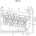
- the overall configuration of an image forming apparatus 100 in which is mounted a developing cartridge (developing device) according to a first embodiment will be described with reference to Fig. 2 .
- the developing cartridge according to the present embodiment is a configuration separate from a drum cartridge that has a photosensitive drum. Both are detachably mountable to the image forming apparatus main body (apparatus main body) 100A, and will be described in detail later.
- FIG. 2 In Fig. 2 , four drum cartridges 9 (9Y, 9C, 9M, 9K) and four developing cartridges 4 (4Y, 4C, 4M, 4K), which are detachably mountable, are mounted via mounting members (omitted from illustration). Note that a developing cartridge 4Y containing yellow toner, a developing cartridge 4M containing magenta toner, a developing cartridge 4C containing cyan toner, and a developing cartridge 4K containing black toner, are of the same configuration.
- a developing cartridge 4Y containing yellow toner, a developing cartridge 4M containing magenta toner, a developing cartridge 4C containing cyan toner, and a developing cartridge 4K containing black toner are of the same configuration.
- the upstream side in the mounting direction of the drum cartridges 9 and developing cartridges 4 as to the image forming apparatus 100 will be defined as a front face side, and the downstream side in the mounting direction as a back face side.
- the drum cartridges 9 and developing cartridges 4 in Fig. 2 are provided in tandem within the apparatus main body 100A, inclined as to the horizontal direction.
- the drum cartridges 9 (9Y, 9C, 9M, 9K) are integrally provided with process means in the vicinity thereof, such as charging rollers 2 (2a, 2b, 2c, 2d), cleaning members 6 (6a, 6b, 6c, 6d) and so forth, besides the photosensitive drums 1 (1a, 1b, 1c, 1d).
- the developing cartridges 4 (4Y, 4M, 4C, 4K) are also integrally provided with process means such as developing blades 35 (35a, 35b, 35c, 35d) and so forth, besides the developing rollers 25 (25a, 25b, 25c, 25d).
- process means in the vicinity thereof, such as charging rollers 2 (2a, 2b, 2c, 2d), cleaning members 6 (6a, 6b, 6c, 6d) and so forth, besides the photosensitive drums 1 (1a, 1b, 1c, 1d).
- the developing cartridges 4 (4Y, 4M, 4C, 4K) are also integrally provided with process means such as developing blades
- the charging roller 2 uniformly charges the surface of the photosensitive drum 1, and the developing roller 25 develops and visualizes a latent image formed on the photosensitive drum 1 by toner.
- the cleaning member 6 transfers the toner image formed on the photosensitive drum 1 onto a recording medium, and thereafter removes residual toner remaining on the photosensitive drum 1.
- a scanner cartridge 3 that selectively exposes the photosensitive drum 1 based on image information and forms the latent image on the photosensitive drum 1 is disposed below the drum cartridge 9 and developing cartridge 4.
- a cassette 17 storing a recording medium S is mounted at a lower portion of the apparatus main body 100A.
- Recoding medium conveying means are provided, such as the recording medium S is conveyed past a secondary transfer roller 69 and fixing unit 74 and to an upper portion of the apparatus main body 100A. That is to say, provided are a feed roller 54 that separates and feeds the recording medium S within the cassette 17 one sheet at a time, a conveying roller pair 76 that conveys the fed recording medium S, and a registration roller pair 55 for synchronization between the latent image formed on the photosensitive drum 1 and the recording medium S.
- the intermediate transfer cartridge 5 is provided with a driving roller 56, a driven roller 57, primary transfer rollers 58 (58a, 58b, 58c, 58d) at positions facing the respective color photosensitive drums 1, and a facing roller 59 facing the secondary transfer roller 69.
- a transfer belt 14 runs over these rollers.
- the transfer belt 14 moves cyclically facing and coming into contact with all photosensitive drums 1. Primary transfer from the photosensitive drums 1 to the transfer belt 14 is performed by applying voltage to the primary transfer rollers 58 (58a, 58b, 58c, 58d). Applying voltage to the facing roller 59 disposed on the inner side of the transfer belt 14, and the secondary transfer roller 69, transfers the toner on the transfer belt 14 onto the recording medium S.
- each photosensitive drum 1 When forming an image, each photosensitive drum 1 is rotated, and the photosensitive drums 1 uniformly charged by the charging rollers 2 are selectively exposed by the scanner cartridges 3. Thus, electrostatic latent images are formed on the photosensitive drums 1. The latent images are then developed by the developing rollers 25. This forms toner images of the respective colors on the respective photosensitive drums 1. The toner images on the photosensitive drums 1 are then overlaid on the transfer belt 14 by primary transfer. Synchronously with this image formation, the registration roller pair 55 conveys the recording medium S to a secondary transfer position (a position where the facing roller 59 and the secondary transfer roller 69 are in contact across the transfer belt 14).
- Secondary transfer of the toner images on the transfer belt 14 onto the recording medium S is performed by applying transfer bias voltage to the secondary transfer roller 69. This forms a color image on the recording medium S.
- the recording medium S on which the color image has been formed is heated and pressurized by the fixing unit 74, thereby fixing the toner image. Thereafter, the recording medium S is discharged to a discharge unit 75 by a discharge roller pair 72.
- the fixing unit 74 is disposed at the upper portion of the apparatus main body 100A.
- the drum cartridge 9 according to the present image forming apparatus will be described with reference to Figs. 3 and 4 .
- the photosensitive drum 1 is rotatably disposed to the cleaning frame 27 of the drum cartridge 9 (9Y, 9M, 9C, 9K) via a drum-front bearing 10 and a drum-rear bearing 11, as illustrated in Fig. 3 .
- a drum coupling 16 is provided at one end side on the axial direction of the photosensitive drum 1.
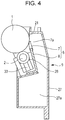
- Fig. 4 is a cross-sectional view of the drum cartridge 9.
- the cleaning frame 27 is provided with the photosensitive drum 1, charging roller 2, and cleaning member 6.
- the charging roller 2 and cleaning member 6 are disposed in the vicinity of the photosensitive drum 1. More specifically, the charging roller 2 is rotatably attached to the drum cartridge 9 via a charging roller bearing 28, and is pressured toward the photosensitive drum 1 by a charging roller pressuring member 33.
- the photosensitive drum 1 is rotationally driven in accordance with image forming operations, by transmitting driving force of a main body driving motor (omitted from illustration) that is a driving source to the drum cartridge 9, and the charging roller 2 rotates following the photosensitive drum 1.
- a main body driving motor (omitted from illustration) that is a driving source
- the cleaning member 6 is configured of an elastic member made of a rubber blade 7, and a cleaning support member 8.
- a tip portion 7a of the rubber blade 7 is disposed in contact with the photosensitive drum 1, facing a direction countering the rotation direction of the photosensitive drum 1. Residual toner removed from the surface of the photosensitive drum 1 by the cleaning member 6 falls into a waste toner chamber 27a of the cleaning frame 27.
- a scoop sheet 21 that prevents waste toner in the waste toner chamber 27a from leaking is fixed to the cleaning frame 27 so as to come into contact with the photosensitive drum 1.
- the term "developing device” as used here means a device that developed an electrostatic latent image formed on a photosensitive drum using a developer, and is configured including developing means, a developing frame supporting the developing means, parts relating to the developing means, and so forth.
- the developing means include a developing roller, applying roller, developing blade, and so forth.
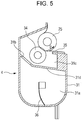
- Fig. 5 is a cross-sectional view orthogonal to the insertion direction of the developing cartridge 4 (4Y, 4M, 4C, 4K) storing toner (developer).
- Fig. 1B is a disassembled configuration diagram of the developing cartridge 4.
- the developing cartridge 4 has, in the developing frame 31, the developing roller 25 that rotates in the direction of the arrow B in contact with the photosensitive drum 1, a toner supply roller 34 that rotates in contact with the developing roller 25, the developing blade 35 that regulates toner on the developing roller 25, and a conveying member 36.
- the developing frame 31 includes a developing chamber 31c where the developing roller 25 is disposed, and a toner storage chamber 31a provided below the developing chamber 31c. These chambers are partitioned by a partition 31d.
- the partition 31d is provided with an opening 31b that toner passes through when conveying toner from the toner storage chamber 31a to the developing chamber 31c.
- the toner storage chamber 31a of the developing frame 31 is provided with the conveying member 36 that agitates the stored toner, and also conveys toner to the developing chamber 31c via the opening 31b.
- the toner supply roller 34 is provided in parallel with the axial direction of the developing roller 25 ( Fig. 5 ).
- the developing roller 25 and toner supply roller 34 are rotatably supported by the developing frame 31, via a developing unit front bearing 12 and a developing unit rear bearing 13, serving as supporting members or supporting frames illustrated in Fig. 1B .
- a developing unit coupling 23 is provided at the back side portion of the toner supply roller 34, as illustrated in Fig. 1B .
- the driving force of the main body driving motor (omitted from illustration) that is the driving source is transmitted from the developing unit coupling 23 to the toner supply roller 34.
- a toner supply gear 30 is provided at the front end portion of the toner supply roller 34.
- a developing unit gear 29 that meshes with the toner supply gear 30 is provided on the front end portion of the developing roller 25. Accordingly, the driving force of the main body driving motor can be transmitted to the developing unit coupling 23, and the toner supply roller 34 and developing roller 25 can be rotationally driving in accordance with image forming operations.
- a gear cover 20 that is part of the developing frame 31 is provided on the outer side of the developing unit gear 29 and toner supply gear 30.
- a front-side end member 37 and a back-side end member 38 are further provided to one end and the other end of the developing frame 31 in the developing roller axial direction.
- a hole 38a that engages a boss 13a provided to the developing unit rear bearing 13 is provided in the back-side end member 38.
- a hole 37a that engages a boss 20a provided to the gear cover 20 is provided in the front-side end member 37.
- the front-side end member 37 and back-side end member 38 are rotatably attached as to an axis Y connecting the boss 13a of the developing unit rear bearing 13 and the boss 20a of the gear cover 20.
- the front-side end member 37 and back-side end member 38 are independently rotatable as to the developing frame 31.
- the configuration of inserting the drum cartridge 9 and developing cartridge 4 into an opening portion 101 (101a, 101b, 101c, 101d) of the apparatus main body 100A is a configuration where the direction of insertion is a direction (direction of arrow F) parallel to the axial direction of the photosensitive drum 1 (1a, 1b, 1c, 1d). Further, the configuration is such that the drum cartridge 9 and developing cartridge 4 are inserted from the front side toward the back side.
- the upstream side of the insertion direction of the drum cartridge 9 and developing cartridge 4 is defined as the front side in the present embodiment, and the downstream side as the back side.
- a main body mounting upper guide portion 103 (103a, 103b, 103c, 103d), which is a first main body guide portion, is disposed at the upper side within the apparatus main body 100A, and a main body mounting lower guide portion 102 (102a, 102b, 102c, 102d), which is a second main body guide portion, is disposed at the lower side.
- the main body mounting upper guide portion 103 and main body mounting lower guide portion 102 are each guide forms extending along the insertion direction F of the drum cartridge 9.
- the drum cartridge 9 is loaded on the front side in the mounting direction of the main body mounting lower guide portion 102, and moved along the main body mounting upper guide portion 103 and main body mounting lower guide portion 102 in the insertion direction F, and thus is inserted into to the apparatus main body 100A.
- the developing cartridge 4 is also inserted into the apparatus main body 100A in the same way as the drum cartridge 9.
- a main body mounting upper guide portion 105 (105a, 105b, 105c, 105d), which is a third main body guide portion, is disposed at the upper side within the apparatus main body 100A, and a main body mounting lower guide portion 104 (104a, 104b, 104c, 104d), which is a fourth main body guide portion, is disposed at the lower side.
- the main body mounting upper guide portion 105 and main body mounting lower guide portion 104 are each guide forms extending along the insertion direction F of the developing cartridge 4.
- the developing cartridge 4 is loaded on the front side in the mounting direction of the main body mounting lower guide portion 104, and moved along the main body mounting upper guide portion 105 and main body mounting lower guide portion 104 in the insertion direction F, and thus is inserted into to the apparatus main body 100A.
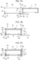
- Fig. 7A is a diagram for describing a state before mounting the developing cartridge 4 to the apparatus main body 100A.
- Fig. 7B is a diagram for describing a state where the developing cartridge 4 has been mounted until abutting a back-side plate 98 of the apparatus main body 100A.
- the main body mounting lower guide portion 104 provided to the apparatus main body 100A has a back-side main body pressuring member 106, a back-side main body pressuring spring 108, a front-side main body pressuring member 107, and a front-side main body pressuring spring 109, for pressuring and positioning the developing cartridge 4 as to the apparatus main body 100A.
- an insertion guide portion 38b of the back-side end member 38 rides up on the back-side main body pressuring member 106, and an insertion guide portion 37b of the front-side end member 37 rides up on the front-side main body pressuring member 107.
- the developing cartridge 4 moves upwards in the vertical direction of the apparatus main body 100A.
- FIG. 7C is a diagram for describing a state where the developing cartridge 4 has been positioned as to the apparatus main body 100A.
- a front door 110 of the apparatus main body 100A is closed, and in conjunction with this, the main body mounting lower guide portion 104 that has the main body pressuring members 106 and 107 and the main body pressuring springs 108 and 109 moves upwards in the vertical direction of the apparatus main body 100A.
- a back-side positioning portion 38d provided to the back-side end member 38 comes into contact with a positioning portion 98a that is a main body positioning portion of the back-side plate 98.
- a front-side positioning portion 37c provided to the front-side end member 37 comes into contact with a positioning portion 99a that is a main body positioning portion of a front-side plate 99.
- the developing cartridge 4 is positioned as to the apparatus main body 100A.
- a boss 38e serving as a rotation stopper for the back-side end member 38 is provided to the back-side end member 38 as illustrated in Fig. 8 , the boss 38e fitting to a rotating stopping hole 98b provided to the back-side plate 98. This prevents the back-side end member 38 from rotating within the apparatus main body 100A.
- a rotation stopper 37d serving as a rotation stopper for the front-side end member 37 is provided to the front-side end member 37 as well, and fits to a rotation stopper portion 104e provided to the main body mounting lower guide portion 104. Accordingly, the front-side end member 37 is prevented from rotating within the apparatus main body 100A.
- the back-side end member 38 and front-side end member 37 of the developing cartridge 4 is fixed to the apparatus main body 100A by mounting the developing cartridge 4 to the apparatus main body 100A, and the developing frame 31 can pivot as to the apparatus main body 100A.
- FIGs. 9A and 9B are diagrams for describing separation operations of the developing cartridge 4.
- a separation member 32 is provided to the apparatus main body 100A at a predetermined position in the longitudinal direction of the developing cartridge 4.
- Urging force is applied to the developing roller 25 when forming images, by a contact force pressuring portion 32a of the separation member 32 coming into contact with a contact force receiving portion 31f of the developing frame 31, and thus the developing roller 25 is in a state of being in contact with the photosensitive drum 1.
- the separation member 32 moves in the direction of the arrow G, the contact state of the contact force pressuring portion 32a of the separation member 32 and the contact force receiving portion 31f of the developing frame 31 is disengaged first.
- a separation force pressuring portion 32b of the separation member 32 comes into contact with a separation force receiving portion 31e of the developing frame 31, and as the separation member 32 moves in the direction of the arrow G, the developing frame 31 rotates in the direction of arrow W1, centered on the axis Y. As a result, the developing roller 25 moves to a position separated from photosensitive drum 1.
- Figs. 10A and 10B are diagrams describing contact operations of the developing cartridge 4.
- the separation member 32 moves in the direction of the arrow H
- the contact state between the separation force pressuring portion 32b of the separation member 32 and the separation force receiving portion 31e of the developing frame 31 is disengaged first.
- the contact force pressuring portion 32a of the separation member 32 comes into contact with the contact force receiving portion 31f of the developing frame 31, and the developing frame 31 rotates in the direction of arrow W2, centered on the axis Y.
- the developing roller 25 moves to a position in contact with photosensitive drum 1.
- the developing roller 25 comes into contact with the photosensitive drum 1 at a predetermined pressure, by a pressuring mechanism (omitted from illustration) provided to the separation member 32. Also, the developing cartridge 4 moves to a contact position with the photosensitive drum 1 when forming images, and otherwise moves to and is kept at a separation position, due to this contact/separation mechanism. Accordingly, effects on image quality due to deformation of the developing roller 25 can be suppressed.
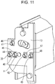
- FIG. 11 is a schematic diagram at the back side when the developing cartridge 4 is mounted to the apparatus main body 100A.
- Multiple developing unit side electric contact points that come into contact with main body side electric contact points 39, 40, 41, 42, and 43, are provided on the developing unit rear bearing 13. These are a developing roller contact point 44, toner supply roller contact point 45, developing blade contact point 46, and residual toner detection contact points 47 and 48.
- These multiple electric contact points are formed of an electroconductive resin material. These are integrally formed with the developing unit rear bearing 13 disposed at one end of the developing roller 25 in the axial direction (longitudinal direction), and are provided on a face intersecting the axial direction of the developing roller 25.
- the configuration for applying voltage to the developing roller 25 and toner supply roller 34 and the configuration for applying voltage to the developing blade 35 and a residual toner detecting unit are the same configuration. Accordingly, the configuration for applying voltage to the developing roller 25 and the developing blade 35 will be exemplified in the description of the configuration for applying voltage to the developing cartridge 4.
- Fig. 12 is a cross-sectional view illustrating the configuration for supplying electric power from the main body side electric contact point 39 to the developing roller 25.
- the developing roller contact point 44 has a first contact face 44a that comes into contact with the main body side electric contact point 39, and a second contact face 44b that comes into contact with a developing roller core 25e.
- the first contact face 44a is provided on the back side of the developing unit rear bearing 13, and is in contact with the main body side electric contact point 39 under a predetermined amount of pressure.
- the second contact face 44b rotatably supports the developing roller core 25e, and is in contact with the peripheral face and end face of the developing roller core 25e.
- Fig. 13 is a cross-sectional view illustrating the configuration for supplying electric power from the main body side electric contact point 41 to the developing blade 35.
- the developing blade contact point 46 has a first contact face 46a that comes into contact with the main body side electric contact point 41, and a second contact face 46b that comes into contact with a developing blade supporting plate 35e.
- the first contact face 46a is provided on the back side of the developing unit rear bearing 13, and is in contact with the main body side electric contact point 41 under a predetermined amount of pressure.
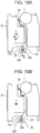
- Fig. 1A is a configuration diagram of the back end portion of the developing cartridge 4
- Fig. 1B is a disassembled configuration diagram of the developing cartridge 4.
- the axis Y of the developing frame 31 is laid out as illustrated in Fig. 1A , in plan view perpendicular to the axial direction of the developing roller 25. That is to say, the axis Y is disposed within a polygonal region (having an area of K) formed of the outer shapes of the developing roller contact point 44, toner supply roller contact point 45, developing blade contact point 46, and residual toner detection contact points 47 and 48, and straight lines connecting these outer shapes.
- a boss 13a serving as the axis Y of the developing cartridge 4, and multiple electric contact points (44, 45, 46, 47, and 48) are provided on the developing unit rear bearing 13 of the developing cartridge 4.
- the boss 13a is provided within a polygonal region having the greatest area formed of the outer shapes of the multiple electric contact points and straight lines connecting the outer shapes of the multiple electric contact points, in a plane perpendicular to the axis Y. Accordingly, in a case of a layout of developing unit side electric contact points such as illustrated in Fig. 1A , a polygon having the greatest area is formed by using all developing unit side electric contact points.
- a polygon having the greatest area is formed by using the outer shapes of the developing roller contact point 44, developing blade contact point 46, and residual toner detection contact point 48, which is part of all developing unit side electric contact points, and straight lines connecting these outer shapes.
- the developing unit side electric contact points necessary for forming a polygon are thus selected in the present embodiment such that a polygon having the greatest area is formed on a plane perpendicular to the axis Y. Accordingly, there may be cases where all developing unit side electric contact points are used for forming the polygon ( Fig. 1A ), and there may be cases where only a part is used ( Fig. 14 ).
- the developing unit side electric contact points are laid out so that the axis Y is interposed therebetween. Accordingly, when urging force is received from the main body side electric contact points 39, 40, 42, and 43, as illustrated in Fig. 15 , force is applied symmetrically with regard to the axis Y. That is to say, the situation in conventional arrangements, where the developing frame 31 inclines as to the axis Y under pressure that the multiple electric contact points receive from main body electric contact points provided to the image forming apparatus main body, and the pressure of the main body electric contact points decreases due to the inclination, can be suppressed. As a result, stable voltage application from the apparatus main body 100A to each process means can be realized, without having to set the pressure of the main body electric contact points taking into consideration reduction in pressure.
- Suppressing the inclination of the developing frame 31 as to the axis Y enables the below-described sliding resistance to be suppressed when the developing frame 31 pivots during the contact/separation operations illustrated in Figs. 9 and 10 .
- sliding resistance between the boss 13a of the developing unit rear bearing 13 and the hole 38a of the back-side end member 38, and the boss 20a of the gear cover 20 and the hole 37a of the front-side end member 37 can be reduced. Accordingly, the pressure when pressing the developing roller 25 into contact with the photosensitive drum 1 is stabilized, so image quality can be improved.
- the axis Y of the developing frame 31 is situated in the vicinity of a center-of-gravity position G1 when the developing frame 31 is maximally filled with developer, and a center-of-gravity position G2 when no developer is stored in the developing frame 31, as viewed in a plane perpendicular to the axial direction of the developing roller 25.
- the center-of-gravity positions G1 and G2 are within the above-described polygonal region.
- positioning the axis Y near the center of gravity of the developing frame 31 enables the effects of moment generated by the weight of the developing frame 31 during the contact/separation operations of the developing roller 25 as to the photosensitive drum 1 can be reduced. Accordingly, the moment necessary for turning (pivoting) the developing frame 31 during contact/separation operations of the separation member 32 illustrated in Figs. 9 and 10 can be reduced, so the output pressure of the pressuring mechanism of the separation member 32 can be small.
- Fig. 16 illustrates a modification suitable for furthering the advantages of the above-described embodiment.
- the toner supply roller contact point 45 and residual toner detection contact point 47 are formed on a same circle of which the axis Y is the center, i.e., equidistantly from the axis Y.
- the axis Y is also disposed within a polygon (hatched portion M) formed by the outer shapes of the toner supply roller contact point 45 and residual toner detection contact point 47 and straight lines connecting these outer shapes.
- the toner supply roller contact point 45 and residual toner detection contact point 47 are disposed facing each other across the axis Y at the center, and further equidistantly from the axis Y.
- the developing frame 31 is pressured by the main body side electric contact points 40 and 42 disposed symmetrically as to the axis Y, so the developing frame 31 can be suppressed from inclining as to the axis Y by the urging force of the main body side electric contact points 40 and 42.
- Fig. 16 also illustrates an arrangement where the developing roller contact point 44 and residual toner detection contact point 48 are formed on a same circle of which the axis Y is the center, i.e., equidistantly from the axis Y.
- the axis Y is also disposed within a polygon (dashed line portion N) formed by the outer shapes of the developing roller contact point 44, developing blade contact point 46, and residual toner detection contact point 48, and straight lines connecting these outer shapes.
- the developing roller contact point 44, developing blade contact point 46, and residual toner detection contact point 48 are disposed facing each other across the axis Y at the center, and further equidistantly from the axis Y.
- the developing frame 31 is pressured by the main body side electric contact points 39 and 43 disposed symmetrically as to the axis Y, so the developing frame 31 can be suppressed from inclining as to the axis Y by the urging force of the main body side electric contact points 39 and 43.
- stable electric power supply can be performed with suppressed inclination of the developing frame as to the pivot axis. Also, suppressing inclination of the developing frame as to the pivot axis further enables sliding resistance of the pivoting portions to be reduced, so the developing roller can be pressured against the photosensitive drum in a stable manner.
- Fig. 17 is a perspective view illustrating a state where the developing cartridge 4 is mounted to the apparatus main body 100A.
- the boss 13a provided to the developing unit rear bearing 13 is pressured upwards in the vertical direction by a main body pressuring member 98d and a main body pressuring spring 98e provided to the back-side plate 98, and comes into contact with the positioning portion 98a provided to the back-side plate 98.
- the front side of the developing frame 31 is turnably (pivotably) supported by the front-side end member 37, and the back side thereof by the back-side plate 98.
- Advantages the same as those of the first embodiment can be obtained by this configuration as well.
- a third embodiment of the present invention will be described with reference to Figs. 18 and 19 .
- a feature of the present embodiment is that the drum cartridge (photosensitive unit) and developing cartridge are an integrated process cartridge.
- a process cartridge here is an arrangement where part or all of a photosensitive drum and process means that act upon this drum are formed into an integrated cartridge that is detachably mountable to the apparatus main body.
- process means include charging means, developing means, cleaning means, and so forth, that act upon the photosensitive drum. Description will be made in the present embodiment regarding only configuration portions that differ from the first embodiment, and description of configuration portions that are the same as the first embodiment will be omitted.
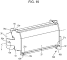
- Figs. 18 and 19 are perspective views illustrating a state where a process cartridge, in which the drum cartridge and developing cartridge according to the first embodiment have been integrated, is mounted to the apparatus main body 100A.
- a front-side pressured portion 27c and a back-side pressured portion 27d are pressured upwards vertically by the back-side main body pressuring member 106, back-side pressuring spring 109, front-side main body pressuring member 107, and front-side pressuring spring 108, provided to the apparatus main body.
- the process cartridge is also positioned as to the apparatus main body 100A by a positioning portion 11a of the drum-rear bearing 11 coming into contact with the positioning portion 98a of the back-side plate 98, and a positioning portion 10a of the drum-front bearing 10 coming into contact with the positioning portion 99a of the front-side plate 99.
- drum-front bearing 10 and drum-rear bearing 11 are provided overlaying the axis Y in a plane perpendicular to the axis Y that is the pivot axis.
- the boss 13a provided to the developing unit rear bearing 13 engages a suspending hole 11b of the drum-rear bearing 11.
- the boss 20a of the gear cover 20 also engages a suspending hole 10b of the drum-front bearing 10. Accordingly, the developing frame 31 is rotatably supported by the cleaning frame 27. Advantages the same as those of the first embodiment can be obtained by this configuration as well.
- a developing device (4) detachably mountable to an image forming apparatus main body (100A), includes a developing frame (31), a developing roller (25), and electric contact points (44, 45, 46, 47, 48) disposed at one end in an axial direction of the developing roller (25).
- the developing device (4) is pivotably centered on a pivot axis (Y) parallel to the axial direction of the developing roller (25), and electrically conducts with the image forming apparatus main body (100A) via the electric contact points (44, 45, 46, 47, 48) when mounted.
- a position of the pivot axis (Y) is within a polygon having a greatest area formed of outer shapes of the electric contact points (44, 45, 46, 47, 48) and straight lines connecting the outer shapes of the electric contact points (44, 45, 46, 47, 48).
Landscapes
- Physics & Mathematics (AREA)
- General Physics & Mathematics (AREA)
- Engineering & Computer Science (AREA)
- Computer Vision & Pattern Recognition (AREA)
- Electrophotography Configuration And Component (AREA)
- Dry Development In Electrophotography (AREA)
Abstract
Description
- The present invention relates to a developing device, a process cartridge, and an image forming apparatus, and is particularly suitable for an image forming apparatus using an electrophotographic image forming process. Examples of such image forming apparatuses include printers (laser beam printers, light-emitting diode (LED) printers, and so forth), copiers, facsimile devices, word processes, multifunctional apparatuses thereof (multifunction printers), and so forth.
- Conventionally, in image forming apparatuses using the electrophotographic image forming process, a photosensitive drum and processing means that act upon the photosensitive drum are fully or partly integrated into a cartridge. A process cartridge system, where this cartridge is detachably mountable to the main body of the image forming apparatus, is employed. According to this process cartridge system, users can perform maintenance of the image forming apparatus by exchanging process cartridges and developing devices, thereby markedly improving operability. Thus, this process cartridge system is in widespread use in electrophotographic image forming apparatuses.
- One of process means acting upon the photosensitive drum is a developing roller that develops developer contained in the cartridge. This developing roller comes into contact with the photosensitive drum, thereby developing an electrostatic latent image formed on the photosensitive drum. However, if this developing roller remains in contact with the photosensitive drum for prolonged periods of time, the developing roller deforms, which affects image quality. Accordingly, a configuration is made where the developing roller comes into contact with the photosensitive drum only when forming images, and at other times is separated from the photosensitive drum, to suppress deformation of the developing roller.
- Now, a conventional developing roller contact/separation operation will be described.
Fig. 20A is a cross-sectional view of a process cartridge where a developingroller 25 is separated from aphotosensitive drum 1. A shaft is inserted through a hole, omitted from illustration, that is provided in a developingframe 31, and ahole 27b provided in acleaning frame 27, with the developingframe 31 being rotatably supported by thecleaning frame 27 with the shaft as a pivot center Y. A pressingmember 32 provided to the image forming apparatus comes into contact with a pressedface 31e of the developingframe 31, whereby the developingroller 25 is urged in the direction of the arrow G, centered on the pivot center Y, and a state of separation from thephotosensitive drum 1 is maintained. - Next,
Fig. 20B is a cross-sectional view of the process cartridge when the developingroller 25 is in contact with thephotosensitive drum 1. When thepressing member 32 moves in the direction of the arrow H, the developingframe 31 rotates in the direction of the arrow C, centered on the pivot center Y, under elastic force of a spring (omitted from illustration) provided to the developingframe 31. The developingroller 25 then comes into contact with thephotosensitive drum 1, and further remains in contact with thephotosensitive drum 1 at a predetermined pressure, by the elastic force of the spring. - In the process cartridge system, there is the need to supply electric power necessary for image formation from the image forming apparatus main body. As for the method of supplying electric power from the image forming apparatus to the process cartridge, an electroconductive elastic member, of which a metal spring provided to the image forming apparatus is representative, comes into contact with an electroconductive contact portion provided to the process cartridge at a predetermined pressure, thereby securing a conduction path. A different voltage needs to be applied in this supply of electric power, for each process means provided to the process cartridge. Thus, the process cartridge needs multiple independent electric contacts, which necessitates a great amount of space for providing the electric contacts.
- There conventionally is known an arrangement where multiple electric contacts are disposed at one end on the longitudinal direction of the process cartridge, and so as to overlap on the contact/separation path of the developing device, thereby realizing reduced size and stable electric power supply for the developing device (Japanese Patent Laid-Open No.
2013-195805 - The pivot center of the developing frame has been provided at one end side in a particular direction in a cross-section of the developing frame orthogonal to the longitudinal direction (the direction in which the shaft extends) of the process cartridge, in the conventional contact/separation configuration of the developing roller. The multiple electric contacts are disposed together at the other end side as to the shaft that is the pivot center, in a particular direction of the developing frame. Accordingly, there has been a problem that the developing frame becomes undesirably inclined due to pressure that the multiple electric contacts receive from the main body electric contacts provided to the image forming apparatus main body, and the pressure of the main body electric contact points decrease due to this inclination. Thus, there has been a need to set the pressure of the main body electric contact points taking into consideration this reduction in pressure.
- It has been found desirable to provide a developing device, a process cartridge, and an image forming apparatus, capable of suppressing the inclination of the developing frame as to the pivot axis and perform stable electric power supply, when main body electric contacts come into contact with multiple electric contacts of the cartridge.
- The present invention in its first aspect provides a developing device as specified in
claims 1 to 7. - The present invention in its second aspect provides an image forming apparatus as specified in claim 8.
- The present invention in its third aspect provides a process cartridge as specified in
claim 9. - The present invention in its fourth aspect provides an image forming apparatus as specified in
claim 10. - Further features of the present invention will become apparent from the following description of exemplary embodiments with reference to the attached drawings.
-
-
Figs. 1A and 1B are explanatory diagrams of the configuration of a developing cartridge according to a first embodiment. -
Fig. 2 is a principal section of an image forming apparatus in which is installed the developing cartridge according to the first embodiment. -
Fig. 3 is an explanatory diagram of a drum cartridge according to a first image forming apparatus. -
Fig. 4 is a principal section of the drum cartridge according to the first image forming apparatus. -
Fig. 5 is a principal section of the developing cartridge according to the first embodiment. -
Fig. 6 is a configuration diagram of mounting the developing cartridge and drum cartridge according to the first embodiment. -
Figs. 7A through 7C are explanatory diagrams of operations when mounting the developing cartridge according to the first embodiment to the image forming apparatus main body. -
Fig. 8 is a configuration explanatory diagram illustrating a state in which the developing cartridge according to the first embodiment is positioned as to the image forming apparatus main body. -
Figs. 9A and 9B are explanatory diagrams of operations regarding a separation operation of the developing cartridge according to the first embodiment. -
Figs. 10A and 10B are explanatory diagrams of operations regarding a contact operation of the developing cartridge according to the first embodiment. -
Fig. 11 is a configuration explanatory diagram for describing the electricity conducting method of the developing cartridge and image forming apparatus main body according to the first embodiment. -
Fig. 12 is a cross-sectional view for describing the electricity conducting method of the developing roller of the developing cartridge and the image forming apparatus main body, according to the first embodiment. -
Fig. 13 is a cross-sectional view for describing the electricity conducting method of the developing blade of the developing cartridge and the image forming apparatus main body, according to the first embodiment. -
Fig. 14 is a configuration diagram of a developing cartridge according to a modification of the first embodiment. -
Fig. 15 is an explanatory diagram illustrating a layout where developing-side electric contacts face each other with a pivot axis as the center. -
Fig. 16 is a configuration diagram of a modification of the developing cartridge according to the first embodiment. -
Fig. 17 is a configuration explanatory diagram illustrating a state in which a developing cartridge according to a second embodiment is positioned as to the image forming apparatus main body. -
Fig. 18 is a configuration explanatory diagram illustrating a state in which a process cartridge according to a third embodiment is positioned as to the image forming apparatus main body. -
Fig. 19 is a configuration explanatory diagram illustrating a state in which a process cartridge according to the third embodiment is positioned as to the image forming apparatus main body. -
Figs. 20A and 20B are configuration explanatory diagrams for describing a contact/separation configuration in a conventional configuration. - Embodiments of the present invention will be described in detail below, with reference to the attached drawings.
- The overall configuration of an
image forming apparatus 100 in which is mounted a developing cartridge (developing device) according to a first embodiment will be described with reference toFig. 2 . The developing cartridge according to the present embodiment is a configuration separate from a drum cartridge that has a photosensitive drum. Both are detachably mountable to the image forming apparatus main body (apparatus main body) 100A, and will be described in detail later. - In
Fig. 2 , four drum cartridges 9 (9Y, 9C, 9M, 9K) and four developing cartridges 4 (4Y, 4C, 4M, 4K), which are detachably mountable, are mounted via mounting members (omitted from illustration). Note that a developingcartridge 4Y containing yellow toner, a developingcartridge 4M containing magenta toner, a developingcartridge 4C containing cyan toner, and a developingcartridge 4K containing black toner, are of the same configuration. - In the same way, a developing
cartridge 4Y containing yellow toner, a developingcartridge 4M containing magenta toner, a developingcartridge 4C containing cyan toner, and a developingcartridge 4K containing black toner, are of the same configuration. The upstream side in the mounting direction of thedrum cartridges 9 and developingcartridges 4 as to theimage forming apparatus 100 will be defined as a front face side, and the downstream side in the mounting direction as a back face side. Thedrum cartridges 9 and developingcartridges 4 inFig. 2 are provided in tandem within the apparatusmain body 100A, inclined as to the horizontal direction. - The drum cartridges 9 (9Y, 9C, 9M, 9K) are integrally provided with process means in the vicinity thereof, such as charging rollers 2 (2a, 2b, 2c, 2d), cleaning members 6 (6a, 6b, 6c, 6d) and so forth, besides the photosensitive drums 1 (1a, 1b, 1c, 1d). The developing cartridges 4 (4Y, 4M, 4C, 4K) are also integrally provided with process means such as developing blades 35 (35a, 35b, 35c, 35d) and so forth, besides the developing rollers 25 (25a, 25b, 25c, 25d). Note that in the following description, members of which there are a plurality may be referred to individually in single form, collectively in single form, or as a plurality, depending on context.
- The charging
roller 2 uniformly charges the surface of thephotosensitive drum 1, and the developingroller 25 develops and visualizes a latent image formed on thephotosensitive drum 1 by toner. The cleaningmember 6 transfers the toner image formed on thephotosensitive drum 1 onto a recording medium, and thereafter removes residual toner remaining on thephotosensitive drum 1. Ascanner cartridge 3 that selectively exposes thephotosensitive drum 1 based on image information and forms the latent image on thephotosensitive drum 1 is disposed below thedrum cartridge 9 and developingcartridge 4. - A
cassette 17 storing a recording medium S is mounted at a lower portion of the apparatusmain body 100A. Recoding medium conveying means are provided, such as the recording medium S is conveyed past asecondary transfer roller 69 and fixingunit 74 and to an upper portion of the apparatusmain body 100A. That is to say, provided are afeed roller 54 that separates and feeds the recording medium S within thecassette 17 one sheet at a time, a conveyingroller pair 76 that conveys the fed recording medium S, and aregistration roller pair 55 for synchronization between the latent image formed on thephotosensitive drum 1 and the recording medium S. - An intermediate transfer cartridge 5 serving as intermediate transfer means, for transferring toner images formed on the photosensitive drums 1 (1a, 1b, 1c, 1d), is disposed above the
drum cartridge 9 and developingcartridge 4. The intermediate transfer cartridge 5 is provided with a drivingroller 56, a drivenroller 57, primary transfer rollers 58 (58a, 58b, 58c, 58d) at positions facing the respective colorphotosensitive drums 1, and a facingroller 59 facing thesecondary transfer roller 69. Atransfer belt 14 runs over these rollers. - The
transfer belt 14 moves cyclically facing and coming into contact with allphotosensitive drums 1. Primary transfer from thephotosensitive drums 1 to thetransfer belt 14 is performed by applying voltage to the primary transfer rollers 58 (58a, 58b, 58c, 58d). Applying voltage to the facingroller 59 disposed on the inner side of thetransfer belt 14, and thesecondary transfer roller 69, transfers the toner on thetransfer belt 14 onto the recording medium S. - When forming an image, each
photosensitive drum 1 is rotated, and thephotosensitive drums 1 uniformly charged by the chargingrollers 2 are selectively exposed by thescanner cartridges 3. Thus, electrostatic latent images are formed on thephotosensitive drums 1. The latent images are then developed by the developingrollers 25. This forms toner images of the respective colors on the respectivephotosensitive drums 1. The toner images on thephotosensitive drums 1 are then overlaid on thetransfer belt 14 by primary transfer. Synchronously with this image formation, theregistration roller pair 55 conveys the recording medium S to a secondary transfer position (a position where the facingroller 59 and thesecondary transfer roller 69 are in contact across the transfer belt 14). - Secondary transfer of the toner images on the
transfer belt 14 onto the recording medium S is performed by applying transfer bias voltage to thesecondary transfer roller 69. This forms a color image on the recording medium S. The recording medium S on which the color image has been formed is heated and pressurized by the fixingunit 74, thereby fixing the toner image. Thereafter, the recording medium S is discharged to adischarge unit 75 by adischarge roller pair 72. Note that the fixingunit 74 is disposed at the upper portion of the apparatusmain body 100A. - The
drum cartridge 9 according to the present image forming apparatus will be described with reference toFigs. 3 and4 . Thephotosensitive drum 1 is rotatably disposed to thecleaning frame 27 of the drum cartridge 9 (9Y, 9M, 9C, 9K) via a drum-front bearing 10 and a drum-rear bearing 11, as illustrated inFig. 3 . Adrum coupling 16 is provided at one end side on the axial direction of thephotosensitive drum 1. -
Fig. 4 is a cross-sectional view of thedrum cartridge 9. Thecleaning frame 27 is provided with thephotosensitive drum 1, chargingroller 2, and cleaningmember 6. The chargingroller 2 and cleaningmember 6 are disposed in the vicinity of thephotosensitive drum 1. More specifically, the chargingroller 2 is rotatably attached to thedrum cartridge 9 via a chargingroller bearing 28, and is pressured toward thephotosensitive drum 1 by a chargingroller pressuring member 33. Thus, thephotosensitive drum 1 is rotationally driven in accordance with image forming operations, by transmitting driving force of a main body driving motor (omitted from illustration) that is a driving source to thedrum cartridge 9, and the chargingroller 2 rotates following thephotosensitive drum 1. - The cleaning
member 6 is configured of an elastic member made of a rubber blade 7, and a cleaning support member 8. Atip portion 7a of the rubber blade 7 is disposed in contact with thephotosensitive drum 1, facing a direction countering the rotation direction of thephotosensitive drum 1. Residual toner removed from the surface of thephotosensitive drum 1 by the cleaningmember 6 falls into awaste toner chamber 27a of thecleaning frame 27. Ascoop sheet 21 that prevents waste toner in thewaste toner chamber 27a from leaking is fixed to thecleaning frame 27 so as to come into contact with thephotosensitive drum 1. - Next, the developing
cartridge 4 serving as a developing device will be described with reference toFigs. 5 and1B . The term "developing device" as used here means a device that developed an electrostatic latent image formed on a photosensitive drum using a developer, and is configured including developing means, a developing frame supporting the developing means, parts relating to the developing means, and so forth. Examples of the developing means include a developing roller, applying roller, developing blade, and so forth. -
Fig. 5 is a cross-sectional view orthogonal to the insertion direction of the developing cartridge 4 (4Y, 4M, 4C, 4K) storing toner (developer).Fig. 1B is a disassembled configuration diagram of the developingcartridge 4. - The developing
cartridge 4 has, in the developingframe 31, the developingroller 25 that rotates in the direction of the arrow B in contact with thephotosensitive drum 1, atoner supply roller 34 that rotates in contact with the developingroller 25, the developingblade 35 that regulates toner on the developingroller 25, and a conveyingmember 36. - The developing
frame 31 includes a developingchamber 31c where the developingroller 25 is disposed, and atoner storage chamber 31a provided below the developingchamber 31c. These chambers are partitioned by apartition 31d. Thepartition 31d is provided with anopening 31b that toner passes through when conveying toner from thetoner storage chamber 31a to the developingchamber 31c. Thetoner storage chamber 31a of the developingframe 31 is provided with the conveyingmember 36 that agitates the stored toner, and also conveys toner to the developingchamber 31c via theopening 31b. - The
toner supply roller 34 is provided in parallel with the axial direction of the developing roller 25 (Fig. 5 ). The developingroller 25 andtoner supply roller 34 are rotatably supported by the developingframe 31, via a developing unit front bearing 12 and a developing unitrear bearing 13, serving as supporting members or supporting frames illustrated inFig. 1B . - Now, a developing
unit coupling 23 is provided at the back side portion of thetoner supply roller 34, as illustrated inFig. 1B . Thus, the driving force of the main body driving motor (omitted from illustration) that is the driving source, is transmitted from the developingunit coupling 23 to thetoner supply roller 34. - On the other hand, a
toner supply gear 30 is provided at the front end portion of thetoner supply roller 34. A developingunit gear 29 that meshes with thetoner supply gear 30 is provided on the front end portion of the developingroller 25. Accordingly, the driving force of the main body driving motor can be transmitted to the developingunit coupling 23, and thetoner supply roller 34 and developingroller 25 can be rotationally driving in accordance with image forming operations. Agear cover 20 that is part of the developingframe 31 is provided on the outer side of the developingunit gear 29 andtoner supply gear 30. - As illustrated in
Fig. 1B , a front-side end member 37 and a back-side end member 38 are further provided to one end and the other end of the developingframe 31 in the developing roller axial direction. Ahole 38a that engages aboss 13a provided to the developing unitrear bearing 13 is provided in the back-side end member 38. Ahole 37a that engages aboss 20a provided to thegear cover 20 is provided in the front-side end member 37. The front-side end member 37 and back-side end member 38 are rotatably attached as to an axis Y connecting theboss 13a of the developing unitrear bearing 13 and theboss 20a of thegear cover 20. Thus, the front-side end member 37 and back-side end member 38 are independently rotatable as to the developingframe 31. - Next, a configuration for inserting the
drum cartridge 9 and developingcartridge 4 into the apparatusmain body 100A will be described with reference toFig. 6 . Note that in the present embodiment, the configuration of inserting thedrum cartridge 9 and developingcartridge 4 into an opening portion 101 (101a, 101b, 101c, 101d) of the apparatusmain body 100A is a configuration where the direction of insertion is a direction (direction of arrow F) parallel to the axial direction of the photosensitive drum 1 (1a, 1b, 1c, 1d). Further, the configuration is such that thedrum cartridge 9 and developingcartridge 4 are inserted from the front side toward the back side. The upstream side of the insertion direction of thedrum cartridge 9 and developingcartridge 4 is defined as the front side in the present embodiment, and the downstream side as the back side. - A main body mounting upper guide portion 103 (103a, 103b, 103c, 103d), which is a first main body guide portion, is disposed at the upper side within the apparatus
main body 100A, and a main body mounting lower guide portion 102 (102a, 102b, 102c, 102d), which is a second main body guide portion, is disposed at the lower side. The main body mounting upper guide portion 103 and main body mounting lower guide portion 102 are each guide forms extending along the insertion direction F of thedrum cartridge 9. Thedrum cartridge 9 is loaded on the front side in the mounting direction of the main body mounting lower guide portion 102, and moved along the main body mounting upper guide portion 103 and main body mounting lower guide portion 102 in the insertion direction F, and thus is inserted into to the apparatusmain body 100A. - The developing
cartridge 4 is also inserted into the apparatusmain body 100A in the same way as thedrum cartridge 9. A main body mounting upper guide portion 105 (105a, 105b, 105c, 105d), which is a third main body guide portion, is disposed at the upper side within the apparatusmain body 100A, and a main body mounting lower guide portion 104 (104a, 104b, 104c, 104d), which is a fourth main body guide portion, is disposed at the lower side. The main body mountingupper guide portion 105 and main body mountinglower guide portion 104 are each guide forms extending along the insertion direction F of the developingcartridge 4. The developingcartridge 4 is loaded on the front side in the mounting direction of the main body mountinglower guide portion 104, and moved along the main body mountingupper guide portion 105 and main body mountinglower guide portion 104 in the insertion direction F, and thus is inserted into to the apparatusmain body 100A. - Next, the operations of mounting the developing
cartridge 4 to the apparatusmain body 100A will be described with reference toFigs. 7A through 8 .Fig. 7A is a diagram for describing a state before mounting the developingcartridge 4 to the apparatusmain body 100A.Fig. 7B is a diagram for describing a state where the developingcartridge 4 has been mounted until abutting a back-side plate 98 of the apparatusmain body 100A. The main body mountinglower guide portion 104 provided to the apparatusmain body 100A has a back-side mainbody pressuring member 106, a back-side mainbody pressuring spring 108, a front-side mainbody pressuring member 107, and a front-side mainbody pressuring spring 109, for pressuring and positioning the developingcartridge 4 as to the apparatusmain body 100A. - When mounting the developing
cartridge 4 to the apparatusmain body 100A, aninsertion guide portion 38b of the back-side end member 38 rides up on the back-side mainbody pressuring member 106, and aninsertion guide portion 37b of the front-side end member 37 rides up on the front-side mainbody pressuring member 107. Thus, the developingcartridge 4 moves upwards in the vertical direction of the apparatusmain body 100A. - An abutting
portion 38c provided to the back-side end member 38 abuts the back-side plate 98 of the apparatusmain body 100A, thereby positioning the developingcartridge 4 in the insertion direction.Fig. 7C is a diagram for describing a state where the developingcartridge 4 has been positioned as to the apparatusmain body 100A. Afront door 110 of the apparatusmain body 100A is closed, and in conjunction with this, the main body mountinglower guide portion 104 that has the mainbody pressuring members main body 100A. - In conjunction with this, a back-
side positioning portion 38d provided to the back-side end member 38 comes into contact with apositioning portion 98a that is a main body positioning portion of the back-side plate 98. Further, a front-side positioning portion 37c provided to the front-side end member 37 comes into contact with apositioning portion 99a that is a main body positioning portion of a front-side plate 99. Thus, the developingcartridge 4 is positioned as to the apparatusmain body 100A. - Further, a
boss 38e serving as a rotation stopper for the back-side end member 38 is provided to the back-side end member 38 as illustrated inFig. 8 , theboss 38e fitting to a rotating stoppinghole 98b provided to the back-side plate 98. This prevents the back-side end member 38 from rotating within the apparatusmain body 100A. In the same way, arotation stopper 37d serving as a rotation stopper for the front-side end member 37 is provided to the front-side end member 37 as well, and fits to arotation stopper portion 104e provided to the main body mountinglower guide portion 104. Accordingly, the front-side end member 37 is prevented from rotating within the apparatusmain body 100A. - Thus, the back-
side end member 38 and front-side end member 37 of the developingcartridge 4 is fixed to the apparatusmain body 100A by mounting the developingcartridge 4 to the apparatusmain body 100A, and the developingframe 31 can pivot as to the apparatusmain body 100A. - Next, the contact/separation operations of the
photosensitive drum 1 and developingroller 25 will be described.Figs. 9A and 9B are diagrams for describing separation operations of the developingcartridge 4. Aseparation member 32 is provided to the apparatusmain body 100A at a predetermined position in the longitudinal direction of the developingcartridge 4. - Urging force is applied to the developing
roller 25 when forming images, by a contactforce pressuring portion 32a of theseparation member 32 coming into contact with a contactforce receiving portion 31f of the developingframe 31, and thus the developingroller 25 is in a state of being in contact with thephotosensitive drum 1. However, when theseparation member 32 moves in the direction of the arrow G, the contact state of the contactforce pressuring portion 32a of theseparation member 32 and the contactforce receiving portion 31f of the developingframe 31 is disengaged first. - As the
separation member 32 moves further in the direction of the arrow G, a separationforce pressuring portion 32b of theseparation member 32 comes into contact with a separationforce receiving portion 31e of the developingframe 31, and as theseparation member 32 moves in the direction of the arrow G, the developingframe 31 rotates in the direction of arrow W1, centered on the axis Y. As a result, the developingroller 25 moves to a position separated fromphotosensitive drum 1. - Next,
Figs. 10A and 10B are diagrams describing contact operations of the developingcartridge 4. When theseparation member 32 moves in the direction of the arrow H, the contact state between the separationforce pressuring portion 32b of theseparation member 32 and the separationforce receiving portion 31e of the developingframe 31 is disengaged first. As theseparation member 32 further moves in the direction of the arrow H, the contactforce pressuring portion 32a of theseparation member 32 comes into contact with the contactforce receiving portion 31f of the developingframe 31, and the developingframe 31 rotates in the direction of arrow W2, centered on the axis Y. As a result, the developingroller 25 moves to a position in contact withphotosensitive drum 1. - Due to this configuration, after contact, the developing
roller 25 comes into contact with thephotosensitive drum 1 at a predetermined pressure, by a pressuring mechanism (omitted from illustration) provided to theseparation member 32. Also, the developingcartridge 4 moves to a contact position with thephotosensitive drum 1 when forming images, and otherwise moves to and is kept at a separation position, due to this contact/separation mechanism. Accordingly, effects on image quality due to deformation of the developingroller 25 can be suppressed. - Next, the configuration for supplying electric power to the developing
cartridge 4 according to the present embodiment will be described.Fig. 11 is a schematic diagram at the back side when the developingcartridge 4 is mounted to the apparatusmain body 100A. Multiple developing unit side electric contact points that come into contact with main body side electric contact points 39, 40, 41, 42, and 43, are provided on the developing unitrear bearing 13. These are a developingroller contact point 44, toner supplyroller contact point 45, developingblade contact point 46, and residual toner detection contact points 47 and 48. - These multiple electric contact points (44, 45, 46, 47, 48) are formed of an electroconductive resin material. These are integrally formed with the developing unit
rear bearing 13 disposed at one end of the developingroller 25 in the axial direction (longitudinal direction), and are provided on a face intersecting the axial direction of the developingroller 25. - Now, the configuration for applying voltage to the developing
roller 25 andtoner supply roller 34 and the configuration for applying voltage to the developingblade 35 and a residual toner detecting unit (omitted from illustration) are the same configuration. Accordingly, the configuration for applying voltage to the developingroller 25 and the developingblade 35 will be exemplified in the description of the configuration for applying voltage to the developingcartridge 4. -
Fig. 12 is a cross-sectional view illustrating the configuration for supplying electric power from the main body sideelectric contact point 39 to the developingroller 25. The developingroller contact point 44 has afirst contact face 44a that comes into contact with the main body sideelectric contact point 39, and asecond contact face 44b that comes into contact with a developingroller core 25e. Thefirst contact face 44a is provided on the back side of the developing unitrear bearing 13, and is in contact with the main body sideelectric contact point 39 under a predetermined amount of pressure. Thesecond contact face 44b rotatably supports the developingroller core 25e, and is in contact with the peripheral face and end face of the developingroller core 25e. Upon voltage being output to the main body sideelectric contact point 39 under an instruction from a controller (omitted from illustration) of the apparatusmain body 100A, voltage is applied to the surface of the developingroller 25 via the developingroller contact point 44 and the developingroller core 25e. -
Fig. 13 is a cross-sectional view illustrating the configuration for supplying electric power from the main body sideelectric contact point 41 to the developingblade 35. The developingblade contact point 46 has afirst contact face 46a that comes into contact with the main body sideelectric contact point 41, and asecond contact face 46b that comes into contact with a developingblade supporting plate 35e. Thefirst contact face 46a is provided on the back side of the developing unitrear bearing 13, and is in contact with the main body sideelectric contact point 41 under a predetermined amount of pressure. Upon voltage being output to the main body sideelectric contact point 41 under an instruction from a controller (omitted from illustration) of the apparatusmain body 100A, voltage is applied to the developingblade 35 via the developingblade contact point 46 and the developingblade supporting plate 35e. - Now, description has been made in the present embodiment where an electroconductive resin material is used for the members that electrically conduct from main body side electric contact points to the developing
roller 25 and developingblade 35. However, it is sufficient for electrical connection to the process members to be realized, and there is no particular restriction regarding the materials or means thereof. - The layout of the Y axis that is the axis of rotation (pivot axis) of the developing
cartridge 4 according to the present embodiment, and the developingroller contact point 44, toner supplyroller contact point 45, developingblade contact point 46, and residual toner detection contact points 47 and 47 that are developing unit side electric contact points will be described. The developing unitrear bearing 13 provided at the end side of the developing device (developing cartridge) will also be described in relation with this.Fig. 1A is a configuration diagram of the back end portion of the developingcartridge 4, andFig. 1B is a disassembled configuration diagram of the developingcartridge 4. - The axis Y of the developing
frame 31 is laid out as illustrated inFig. 1A , in plan view perpendicular to the axial direction of the developingroller 25. That is to say, the axis Y is disposed within a polygonal region (having an area of K) formed of the outer shapes of the developingroller contact point 44, toner supplyroller contact point 45, developingblade contact point 46, and residual toner detection contact points 47 and 48, and straight lines connecting these outer shapes. - In
Fig. 1B , aboss 13a serving as the axis Y of the developingcartridge 4, and multiple electric contact points (44, 45, 46, 47, and 48) are provided on the developing unit rear bearing 13 of the developingcartridge 4. Theboss 13a is provided within a polygonal region having the greatest area formed of the outer shapes of the multiple electric contact points and straight lines connecting the outer shapes of the multiple electric contact points, in a plane perpendicular to the axis Y. Accordingly, in a case of a layout of developing unit side electric contact points such as illustrated inFig. 1A , a polygon having the greatest area is formed by using all developing unit side electric contact points. - In a case of a layout of developing unit side electric contact points such as illustrated in
Fig. 14 , a polygon having the greatest area (area L of hatched portion) is formed by using the outer shapes of the developingroller contact point 44, developingblade contact point 46, and residual tonerdetection contact point 48, which is part of all developing unit side electric contact points, and straight lines connecting these outer shapes. - The developing unit side electric contact points necessary for forming a polygon are thus selected in the present embodiment such that a polygon having the greatest area is formed on a plane perpendicular to the axis Y. Accordingly, there may be cases where all developing unit side electric contact points are used for forming the polygon (
Fig. 1A ), and there may be cases where only a part is used (Fig. 14 ). - Thus, due to the axis Y being disposed in a polygonal region, the developing unit side electric contact points are laid out so that the axis Y is interposed therebetween. Accordingly, when urging force is received from the main body side electric contact points 39, 40, 42, and 43, as illustrated in
Fig. 15 , force is applied symmetrically with regard to the axis Y. That is to say, the situation in conventional arrangements, where the developingframe 31 inclines as to the axis Y under pressure that the multiple electric contact points receive from main body electric contact points provided to the image forming apparatus main body, and the pressure of the main body electric contact points decreases due to the inclination, can be suppressed. As a result, stable voltage application from the apparatusmain body 100A to each process means can be realized, without having to set the pressure of the main body electric contact points taking into consideration reduction in pressure. - Suppressing the inclination of the developing
frame 31 as to the axis Y enables the below-described sliding resistance to be suppressed when the developingframe 31 pivots during the contact/separation operations illustrated inFigs. 9 and10 . Specifically, sliding resistance between theboss 13a of the developing unitrear bearing 13 and thehole 38a of the back-side end member 38, and theboss 20a of thegear cover 20 and thehole 37a of the front-side end member 37, can be reduced. Accordingly, the pressure when pressing the developingroller 25 into contact with thephotosensitive drum 1 is stabilized, so image quality can be improved. - The axis Y of the developing
frame 31 is situated in the vicinity of a center-of-gravity position G1 when the developingframe 31 is maximally filled with developer, and a center-of-gravity position G2 when no developer is stored in the developingframe 31, as viewed in a plane perpendicular to the axial direction of the developingroller 25. Specifically, the center-of-gravity positions G1 and G2 are within the above-described polygonal region. - Thus, positioning the axis Y near the center of gravity of the developing
frame 31 enables the effects of moment generated by the weight of the developingframe 31 during the contact/separation operations of the developingroller 25 as to thephotosensitive drum 1 can be reduced. Accordingly, the moment necessary for turning (pivoting) the developingframe 31 during contact/separation operations of theseparation member 32 illustrated inFigs. 9 and10 can be reduced, so the output pressure of the pressuring mechanism of theseparation member 32 can be small. -
Fig. 16 illustrates a modification suitable for furthering the advantages of the above-described embodiment. The toner supplyroller contact point 45 and residual tonerdetection contact point 47 are formed on a same circle of which the axis Y is the center, i.e., equidistantly from the axis Y. The axis Y is also disposed within a polygon (hatched portion M) formed by the outer shapes of the toner supplyroller contact point 45 and residual tonerdetection contact point 47 and straight lines connecting these outer shapes. Thus, the toner supplyroller contact point 45 and residual tonerdetection contact point 47 are disposed facing each other across the axis Y at the center, and further equidistantly from the axis Y. Consequently, the developingframe 31 is pressured by the main body side electric contact points 40 and 42 disposed symmetrically as to the axis Y, so the developingframe 31 can be suppressed from inclining as to the axis Y by the urging force of the main body side electric contact points 40 and 42. -
Fig. 16 also illustrates an arrangement where the developingroller contact point 44 and residual tonerdetection contact point 48 are formed on a same circle of which the axis Y is the center, i.e., equidistantly from the axis Y. The axis Y is also disposed within a polygon (dashed line portion N) formed by the outer shapes of the developingroller contact point 44, developingblade contact point 46, and residual tonerdetection contact point 48, and straight lines connecting these outer shapes. Thus, the developingroller contact point 44, developingblade contact point 46, and residual tonerdetection contact point 48 are disposed facing each other across the axis Y at the center, and further equidistantly from the axis Y. Consequently, the developingframe 31 is pressured by the main body side electric contact points 39 and 43 disposed symmetrically as to the axis Y, so the developingframe 31 can be suppressed from inclining as to the axis Y by the urging force of the main body side electric contact points 39 and 43. - According to the present embodiment as described above, stable electric power supply can be performed with suppressed inclination of the developing frame as to the pivot axis. Also, suppressing inclination of the developing frame as to the pivot axis further enables sliding resistance of the pivoting portions to be reduced, so the developing roller can be pressured against the photosensitive drum in a stable manner.
- Next, a second embodiment of the present invention will be described with reference to
Fig. 17 . Description has been made in the first embodiment where the front-side end member 37 and back-side end member 38 are disposed at the ends of the developingframe 31 in the axial direction of the developing roller. In comparison with this, a feature of the present embodiment is that only the front-side end member 37 is provided. Description will be made in the present embodiment regarding only configuration portions that differ from the first embodiment, and description of configuration portions that are the same as the first embodiment will be omitted. -
Fig. 17 is a perspective view illustrating a state where the developingcartridge 4 is mounted to the apparatusmain body 100A. Theboss 13a provided to the developing unitrear bearing 13 is pressured upwards in the vertical direction by a mainbody pressuring member 98d and a mainbody pressuring spring 98e provided to the back-side plate 98, and comes into contact with thepositioning portion 98a provided to the back-side plate 98. Accordingly, the front side of the developingframe 31 is turnably (pivotably) supported by the front-side end member 37, and the back side thereof by the back-side plate 98. Advantages the same as those of the first embodiment can be obtained by this configuration as well. - Next, a third embodiment of the present invention will be described with reference to
Figs. 18 and19 . Description has been made in the first embodiment where the drum cartridge and developing cartridge (developing device) are separate configurations. In comparison with this, a feature of the present embodiment is that the drum cartridge (photosensitive unit) and developing cartridge are an integrated process cartridge. - A process cartridge here is an arrangement where part or all of a photosensitive drum and process means that act upon this drum are formed into an integrated cartridge that is detachably mountable to the apparatus main body. Examples of process means include charging means, developing means, cleaning means, and so forth, that act upon the photosensitive drum. Description will be made in the present embodiment regarding only configuration portions that differ from the first embodiment, and description of configuration portions that are the same as the first embodiment will be omitted.
-
Figs. 18 and19 are perspective views illustrating a state where a process cartridge, in which the drum cartridge and developing cartridge according to the first embodiment have been integrated, is mounted to the apparatusmain body 100A. In the process cartridge according to the present embodiment, a front-side pressuredportion 27c and a back-side pressuredportion 27d are pressured upwards vertically by the back-side mainbody pressuring member 106, back-side pressuring spring 109, front-side mainbody pressuring member 107, and front-side pressuring spring 108, provided to the apparatus main body. The process cartridge is also positioned as to the apparatusmain body 100A by apositioning portion 11a of the drum-rear bearing 11 coming into contact with thepositioning portion 98a of the back-side plate 98, and apositioning portion 10a of the drum-front bearing 10 coming into contact with thepositioning portion 99a of the front-side plate 99. - In addition, the drum-
front bearing 10 and drum-rear bearing 11 are provided overlaying the axis Y in a plane perpendicular to the axis Y that is the pivot axis. Theboss 13a provided to the developing unitrear bearing 13 engages a suspendinghole 11b of the drum-rear bearing 11. Theboss 20a of thegear cover 20 also engages a suspendinghole 10b of the drum-front bearing 10. Accordingly, the developingframe 31 is rotatably supported by thecleaning frame 27. Advantages the same as those of the first embodiment can be obtained by this configuration as well. - Although preferred embodiments of the present invention have been described above as embodiments, the present invention is not restricted to these, and various modifications may be made within the scope of the present invention.
- While the present invention has been described with reference to exemplary embodiments, it is to be understood that the invention is not limited to the disclosed exemplary embodiments. The scope of the following claims is to be accorded the broadest interpretation so as to encompass all such modifications and equivalent structures and functions.
- A developing device (4), detachably mountable to an image forming apparatus main body (100A), includes a developing frame (31), a developing roller (25), and electric contact points (44, 45, 46, 47, 48) disposed at one end in an axial direction of the developing roller (25). The developing device (4) is pivotably centered on a pivot axis (Y) parallel to the axial direction of the developing roller (25), and electrically conducts with the image forming apparatus main body (100A) via the electric contact points (44, 45, 46, 47, 48) when mounted. In a plane perpendicular to the axial direction of the developing roller (25), a position of the pivot axis (Y) is within a polygon having a greatest area formed of outer shapes of the electric contact points (44, 45, 46, 47, 48) and straight lines connecting the outer shapes of the electric contact points (44, 45, 46, 47, 48).
Claims (10)
- A developing device (4) that is detachably mountable to an image forming apparatus main body (100A), the developing device (4) comprising:a developing frame (31) configured to contain a developer;a developing roller (25) configured to perform developing using the developer; anda plurality of electric contact points (44, 45, 46, 47, 48) disposed at one end in the axial direction of the developing roller (25), on a face that intersects the axial direction,wherein the developing device (4) is pivotably centered on a pivot axis parallel to the axial direction of the developing roller (25), and electrically conducts with the image forming apparatus main body (100A) via the plurality of electric contact points (44, 45, 46, 47, 48) when mounted to the image forming apparatus main body (100A),and wherein, in a plane perpendicular to the axial direction of the developing roller (25), the position of the pivot axis (Y) is within a polygon having a greatest area formed of outer shapes of the plurality of electric contact points (44, 45, 46, 47, 48) and straight lines connecting the outer shapes of the multiple electric contact points (44, 45, 46, 47, 48).
- The developing device (4) according to Claim 1,
wherein the center of gravity of the developing frame (31) is within the region of the polygon in a plane perpendicular to the axial direction of the developing roller (25). - The developing device (4) according to either of Claim 1 or 2, further comprising:a supporting member (12, 13) configured to support the developing roller (25) at an end in the axial direction of the developing roller (25),wherein the plurality of electric contact points (44, 45, 46, 47, 48) are provided to the supporting member (12, 13) .
- The developing device (4) according to Claim 3,
wherein the supporting member (12, 13) pivotably supports the developing frame (31), centered on the pivot axis (Y). - The developing device (4) according to any one of Claims 1 through 4,
wherein the plurality of electric contact points (44, 45, 46, 47, 48) are disposed on a same circle centered on the pivot axis (Y) in a plane that intersects the axial direction. - The developing device (4) according to any one of Claims 1 through 5,
wherein the developing frame (31) is turnably supported by an end member (37, 38) provided at each side in the axial direction of the developing roller (25). - The developing device (4) according to any one of Claims 1 through 5,
wherein the developing frame (31) is supported by an end member (37) provided at one side in the axial direction of the developing roller (25), and a side plate (98) provided to the image forming apparatus main body (100A). - An image forming apparatus (100), comprising:the developing device (4) according to any one of Claims 1 through 7; andthe image forming apparatus main body (100A) to which the developing device (4) is detachably mountable.
- A process cartridge
wherein
a photosensitive unit having a photosensitive drum (1), and
the developing device (4) according to any one of Claims 1 through 7,
are integrated, and arranged to be detachably mountable to the image forming apparatus main body (100A). - An image forming apparatus (100), comprising:the process cartridge according to Claim 9; andthe image forming apparatus main body (100A) to which the process cartridge is detachably mountable.
Applications Claiming Priority (1)
| Application Number | Priority Date | Filing Date | Title |
|---|---|---|---|
| JP2017011091A JP6821450B2 (en) | 2017-01-25 | 2017-01-25 | Develop equipment, process cartridges, and image forming equipment |
Publications (2)
| Publication Number | Publication Date |
|---|---|
| EP3355129A1 true EP3355129A1 (en) | 2018-08-01 |
| EP3355129B1 EP3355129B1 (en) | 2022-05-11 |
Family
ID=61024589
Family Applications (1)
| Application Number | Title | Priority Date | Filing Date |
|---|---|---|---|
| EP18152917.3A Active EP3355129B1 (en) | 2017-01-25 | 2018-01-23 | Developing device, process cartridge, and image forming apparatus |
Country Status (4)
| Country | Link |
|---|---|
| US (1) | US10281873B2 (en) |
| EP (1) | EP3355129B1 (en) |
| JP (1) | JP6821450B2 (en) |
| CN (1) | CN108345203B (en) |
Families Citing this family (9)
| Publication number | Priority date | Publication date | Assignee | Title |
|---|---|---|---|---|
| JP7151106B2 (en) | 2018-03-12 | 2022-10-12 | ブラザー工業株式会社 | Drum cartridge and image forming device |
| JP2020052360A (en) * | 2018-09-28 | 2020-04-02 | ブラザー工業株式会社 | Process cartridge and image formation system |
| JP2020101687A (en) * | 2018-12-21 | 2020-07-02 | キヤノン株式会社 | Development device, process cartridge and image formation device |
| CN109725520B (en) * | 2019-01-14 | 2024-03-12 | 珠海联合天润打印耗材有限公司 | Developing box and processing box thereof |
| CN111435225B (en) * | 2019-01-14 | 2023-08-04 | 江西亿铂电子科技有限公司 | Processing box |
| JP6642754B1 (en) | 2019-02-28 | 2020-02-12 | ブラザー工業株式会社 | Image forming device |
| JP7483541B2 (en) | 2019-09-17 | 2024-05-15 | キヤノン株式会社 | Cartridge and image forming apparatus |
| CN218601686U (en) * | 2021-12-29 | 2023-03-10 | 珠海奔图电子有限公司 | Process cartridge, process cartridge assembly, and image forming apparatus |
| JP2024002835A (en) * | 2022-06-24 | 2024-01-11 | キヤノン株式会社 | Cartridge and image forming device |
Citations (3)
| Publication number | Priority date | Publication date | Assignee | Title |
|---|---|---|---|---|
| US6389250B1 (en) * | 1999-08-30 | 2002-05-14 | Canon Kabushiki Kaisha | Developing device, process cartridge and electrophotographic image forming apparatus |
| JP2013195805A (en) | 2012-03-21 | 2013-09-30 | Canon Inc | Process cartridge, developing device and image forming device |
| EP3211484A1 (en) * | 2016-02-29 | 2017-08-30 | Canon Kabushiki Kaisha | Developing apparatus, process cartridge, and image forming apparatus |
Family Cites Families (27)
| Publication number | Priority date | Publication date | Assignee | Title |
|---|---|---|---|---|
| JP3839932B2 (en) * | 1996-09-26 | 2006-11-01 | キヤノン株式会社 | Process cartridge, electrophotographic image forming apparatus, electrophotographic photosensitive drum and coupling |
| JPH0944057A (en) * | 1995-07-31 | 1997-02-14 | Canon Inc | Process cartridge and image forming apparatus |
| JPH10222041A (en) * | 1996-12-03 | 1998-08-21 | Canon Inc | Process cartridge and electrophotographic image forming apparatus |
| US5887225A (en) * | 1998-01-05 | 1999-03-23 | Xerox Corporation | Solid carbon fiber electrical rod developer bias contacting method |
| JP3768706B2 (en) * | 1998-12-28 | 2006-04-19 | キヤノン株式会社 | Electrophotographic image forming apparatus |
| JP2002062735A (en) * | 2000-06-09 | 2002-02-28 | Canon Inc | Developing device |
| JP4194298B2 (en) * | 2002-05-17 | 2008-12-10 | キヤノン株式会社 | Information storage medium, unit, process cartridge, developing cartridge, and electrophotographic image forming apparatus |
| JP4378221B2 (en) * | 2003-10-08 | 2009-12-02 | キヤノン株式会社 | Process cartridge and electrophotographic image forming apparatus |
| JP4387932B2 (en) * | 2003-12-09 | 2009-12-24 | キヤノン株式会社 | Process cartridge and electrophotographic image forming apparatus |
| US7136608B2 (en) * | 2003-12-19 | 2006-11-14 | Steven Miller | Removable toner cartridge universal adapter |
| JP4040636B2 (en) * | 2005-03-24 | 2008-01-30 | キヤノン株式会社 | Process cartridge and electrophotographic image forming apparatus |
| JP4622830B2 (en) * | 2005-11-30 | 2011-02-02 | ブラザー工業株式会社 | Developing cartridge, process unit, and image forming apparatus |
| JP4095649B1 (en) * | 2006-12-28 | 2008-06-04 | キヤノン株式会社 | Electrophotographic image forming apparatus, process cartridge, and moving member |
| JP5084257B2 (en) * | 2006-12-28 | 2012-11-28 | キヤノン株式会社 | Process cartridge and image forming apparatus using the same |
| JP4458377B2 (en) * | 2007-06-29 | 2010-04-28 | キヤノン株式会社 | Process cartridge and electrophotographic image forming apparatus |
| KR100889820B1 (en) * | 2007-09-19 | 2009-03-20 | 삼성전자주식회사 | Developing apparatus and image forming apparatus having same |
| KR101586472B1 (en) * | 2009-01-23 | 2016-01-15 | 삼성전자 주식회사 | Image forming apparatus |
| EP2776892B1 (en) * | 2011-11-09 | 2019-06-05 | Canon Kabushiki Kaisha | Cartridge comprising an electrode |
| KR101926717B1 (en) * | 2012-10-24 | 2018-12-07 | 에이치피프린팅코리아 유한회사 | image forming apparatus, method for transmitting POWER and METHOD FOR MOUNTING DEVELOPING UNIT USING THE SAME |
| JP6071484B2 (en) * | 2012-11-30 | 2017-02-01 | キヤノン株式会社 | Image forming apparatus |
| JP6566627B2 (en) * | 2014-11-19 | 2019-08-28 | キヤノン株式会社 | Cartridge and image forming apparatus using the same |
| JP6566806B2 (en) * | 2015-09-16 | 2019-08-28 | キヤノン株式会社 | Cartridge and bearing member |
| JP6639183B2 (en) * | 2015-10-14 | 2020-02-05 | キヤノン株式会社 | Process cartridge and image forming apparatus |
| US9563169B1 (en) * | 2015-12-14 | 2017-02-07 | Lexmark International, Inc. | Replaceable unit for an electrophotographic image forming device having a retractable electrical connector |
| KR101756845B1 (en) * | 2015-12-28 | 2017-07-11 | 에스프린팅솔루션 주식회사 | Proicess cartridge and electrophotographic image forming apparatus using the same |
| US10203658B2 (en) * | 2016-03-25 | 2019-02-12 | Brother Kogyo Kabushiki Kaisha | Image forming apparatus having electrical contact |
| JP6880712B2 (en) * | 2016-10-14 | 2021-06-02 | ブラザー工業株式会社 | Drum cartridge and development cartridge |
-
2017
- 2017-01-25 JP JP2017011091A patent/JP6821450B2/en active Active
-
2018
- 2018-01-23 EP EP18152917.3A patent/EP3355129B1/en active Active
- 2018-01-23 US US15/878,118 patent/US10281873B2/en active Active
- 2018-01-24 CN CN201810065937.5A patent/CN108345203B/en active Active
Patent Citations (3)
| Publication number | Priority date | Publication date | Assignee | Title |
|---|---|---|---|---|
| US6389250B1 (en) * | 1999-08-30 | 2002-05-14 | Canon Kabushiki Kaisha | Developing device, process cartridge and electrophotographic image forming apparatus |
| JP2013195805A (en) | 2012-03-21 | 2013-09-30 | Canon Inc | Process cartridge, developing device and image forming device |
| EP3211484A1 (en) * | 2016-02-29 | 2017-08-30 | Canon Kabushiki Kaisha | Developing apparatus, process cartridge, and image forming apparatus |
Also Published As
| Publication number | Publication date |
|---|---|
| JP6821450B2 (en) | 2021-01-27 |
| US10281873B2 (en) | 2019-05-07 |
| CN108345203B (en) | 2021-03-09 |
| US20180210393A1 (en) | 2018-07-26 |
| CN108345203A (en) | 2018-07-31 |
| EP3355129B1 (en) | 2022-05-11 |
| JP2018120077A (en) | 2018-08-02 |
Similar Documents
| Publication | Publication Date | Title |
|---|---|---|
| EP3355129B1 (en) | Developing device, process cartridge, and image forming apparatus | |
| US7486916B2 (en) | Method and apparatus of image forming and process cartridge included in the apparatus | |
| EP2367067B1 (en) | Image forming apparatus having toner cartridge | |
| US9632479B2 (en) | Process cartridge and image forming apparatus | |
| US8515309B2 (en) | Process cartridge, developing cartridge and image forming apparatus | |
| JP7267781B2 (en) | Cartridge remanufacturing method and cartridge | |
| CN112526856B (en) | cartridges and imaging devices | |
| US11709455B2 (en) | Cartridge, process cartridge, and image forming apparatus | |
| JP2007256352A (en) | Image forming apparatus and developing cartridge | |
| JP2006276196A (en) | Process cartridge and electrophotographic image forming apparatus | |
| EP3757681A1 (en) | Image forming apparatus | |
| US20250237994A1 (en) | Cartridge including photosensitive drum and developing roller that can be easily separated | |
| KR102819069B1 (en) | Image forming apparatus | |
| JP2019164389A (en) | Cartridge and image formation apparatus | |
| JP2025099205A (en) | Unit and image forming apparatus |
Legal Events
| Date | Code | Title | Description |
|---|---|---|---|
| PUAI | Public reference made under article 153(3) epc to a published international application that has entered the european phase |
Free format text: ORIGINAL CODE: 0009012 |
|
| STAA | Information on the status of an ep patent application or granted ep patent |
Free format text: STATUS: THE APPLICATION HAS BEEN PUBLISHED |
|
| AK | Designated contracting states |
Kind code of ref document: A1 Designated state(s): AL AT BE BG CH CY CZ DE DK EE ES FI FR GB GR HR HU IE IS IT LI LT LU LV MC MK MT NL NO PL PT RO RS SE SI SK SM TR |
|
| AX | Request for extension of the european patent |
Extension state: BA ME |
|
| STAA | Information on the status of an ep patent application or granted ep patent |
Free format text: STATUS: REQUEST FOR EXAMINATION WAS MADE |
|
| 17P | Request for examination filed |
Effective date: 20190201 |
|
| RBV | Designated contracting states (corrected) |
Designated state(s): AL AT BE BG CH CY CZ DE DK EE ES FI FR GB GR HR HU IE IS IT LI LT LU LV MC MK MT NL NO PL PT RO RS SE SI SK SM TR |
|
| GRAP | Despatch of communication of intention to grant a patent |
Free format text: ORIGINAL CODE: EPIDOSNIGR1 |
|
| STAA | Information on the status of an ep patent application or granted ep patent |
Free format text: STATUS: GRANT OF PATENT IS INTENDED |
|
| INTG | Intention to grant announced |
Effective date: 20211206 |
|
| GRAS | Grant fee paid |
Free format text: ORIGINAL CODE: EPIDOSNIGR3 |
|
| GRAA | (expected) grant |
Free format text: ORIGINAL CODE: 0009210 |
|
| STAA | Information on the status of an ep patent application or granted ep patent |
Free format text: STATUS: THE PATENT HAS BEEN GRANTED |
|
| AK | Designated contracting states |
Kind code of ref document: B1 Designated state(s): AL AT BE BG CH CY CZ DE DK EE ES FI FR GB GR HR HU IE IS IT LI LT LU LV MC MK MT NL NO PL PT RO RS SE SI SK SM TR |
|
| REG | Reference to a national code |
Ref country code: GB Ref legal event code: FG4D |
|
| REG | Reference to a national code |
Ref country code: CH Ref legal event code: EP |
|
| REG | Reference to a national code |
Ref country code: AT Ref legal event code: REF Ref document number: 1491967 Country of ref document: AT Kind code of ref document: T Effective date: 20220515 |
|
| REG | Reference to a national code |
Ref country code: DE Ref legal event code: R096 Ref document number: 602018035238 Country of ref document: DE |
|
| REG | Reference to a national code |
Ref country code: IE Ref legal event code: FG4D |
|
| REG | Reference to a national code |
Ref country code: LT Ref legal event code: MG9D |
|
| REG | Reference to a national code |
Ref country code: NL Ref legal event code: MP Effective date: 20220511 |
|
| REG | Reference to a national code |
Ref country code: AT Ref legal event code: MK05 Ref document number: 1491967 Country of ref document: AT Kind code of ref document: T Effective date: 20220511 |
|
| PG25 | Lapsed in a contracting state [announced via postgrant information from national office to epo] |
Ref country code: SE Free format text: LAPSE BECAUSE OF FAILURE TO SUBMIT A TRANSLATION OF THE DESCRIPTION OR TO PAY THE FEE WITHIN THE PRESCRIBED TIME-LIMIT Effective date: 20220511 Ref country code: PT Free format text: LAPSE BECAUSE OF FAILURE TO SUBMIT A TRANSLATION OF THE DESCRIPTION OR TO PAY THE FEE WITHIN THE PRESCRIBED TIME-LIMIT Effective date: 20220912 Ref country code: NO Free format text: LAPSE BECAUSE OF FAILURE TO SUBMIT A TRANSLATION OF THE DESCRIPTION OR TO PAY THE FEE WITHIN THE PRESCRIBED TIME-LIMIT Effective date: 20220811 Ref country code: NL Free format text: LAPSE BECAUSE OF FAILURE TO SUBMIT A TRANSLATION OF THE DESCRIPTION OR TO PAY THE FEE WITHIN THE PRESCRIBED TIME-LIMIT Effective date: 20220511 Ref country code: LT Free format text: LAPSE BECAUSE OF FAILURE TO SUBMIT A TRANSLATION OF THE DESCRIPTION OR TO PAY THE FEE WITHIN THE PRESCRIBED TIME-LIMIT Effective date: 20220511 Ref country code: HR Free format text: LAPSE BECAUSE OF FAILURE TO SUBMIT A TRANSLATION OF THE DESCRIPTION OR TO PAY THE FEE WITHIN THE PRESCRIBED TIME-LIMIT Effective date: 20220511 Ref country code: GR Free format text: LAPSE BECAUSE OF FAILURE TO SUBMIT A TRANSLATION OF THE DESCRIPTION OR TO PAY THE FEE WITHIN THE PRESCRIBED TIME-LIMIT Effective date: 20220812 Ref country code: FI Free format text: LAPSE BECAUSE OF FAILURE TO SUBMIT A TRANSLATION OF THE DESCRIPTION OR TO PAY THE FEE WITHIN THE PRESCRIBED TIME-LIMIT Effective date: 20220511 Ref country code: ES Free format text: LAPSE BECAUSE OF FAILURE TO SUBMIT A TRANSLATION OF THE DESCRIPTION OR TO PAY THE FEE WITHIN THE PRESCRIBED TIME-LIMIT Effective date: 20220511 Ref country code: BG Free format text: LAPSE BECAUSE OF FAILURE TO SUBMIT A TRANSLATION OF THE DESCRIPTION OR TO PAY THE FEE WITHIN THE PRESCRIBED TIME-LIMIT Effective date: 20220811 Ref country code: AT Free format text: LAPSE BECAUSE OF FAILURE TO SUBMIT A TRANSLATION OF THE DESCRIPTION OR TO PAY THE FEE WITHIN THE PRESCRIBED TIME-LIMIT Effective date: 20220511 |
|
| PG25 | Lapsed in a contracting state [announced via postgrant information from national office to epo] |
Ref country code: RS Free format text: LAPSE BECAUSE OF FAILURE TO SUBMIT A TRANSLATION OF THE DESCRIPTION OR TO PAY THE FEE WITHIN THE PRESCRIBED TIME-LIMIT Effective date: 20220511 Ref country code: PL Free format text: LAPSE BECAUSE OF FAILURE TO SUBMIT A TRANSLATION OF THE DESCRIPTION OR TO PAY THE FEE WITHIN THE PRESCRIBED TIME-LIMIT Effective date: 20220511 Ref country code: LV Free format text: LAPSE BECAUSE OF FAILURE TO SUBMIT A TRANSLATION OF THE DESCRIPTION OR TO PAY THE FEE WITHIN THE PRESCRIBED TIME-LIMIT Effective date: 20220511 Ref country code: IS Free format text: LAPSE BECAUSE OF FAILURE TO SUBMIT A TRANSLATION OF THE DESCRIPTION OR TO PAY THE FEE WITHIN THE PRESCRIBED TIME-LIMIT Effective date: 20220911 |
|
| PG25 | Lapsed in a contracting state [announced via postgrant information from national office to epo] |
Ref country code: SM Free format text: LAPSE BECAUSE OF FAILURE TO SUBMIT A TRANSLATION OF THE DESCRIPTION OR TO PAY THE FEE WITHIN THE PRESCRIBED TIME-LIMIT Effective date: 20220511 Ref country code: SK Free format text: LAPSE BECAUSE OF FAILURE TO SUBMIT A TRANSLATION OF THE DESCRIPTION OR TO PAY THE FEE WITHIN THE PRESCRIBED TIME-LIMIT Effective date: 20220511 Ref country code: RO Free format text: LAPSE BECAUSE OF FAILURE TO SUBMIT A TRANSLATION OF THE DESCRIPTION OR TO PAY THE FEE WITHIN THE PRESCRIBED TIME-LIMIT Effective date: 20220511 Ref country code: EE Free format text: LAPSE BECAUSE OF FAILURE TO SUBMIT A TRANSLATION OF THE DESCRIPTION OR TO PAY THE FEE WITHIN THE PRESCRIBED TIME-LIMIT Effective date: 20220511 Ref country code: DK Free format text: LAPSE BECAUSE OF FAILURE TO SUBMIT A TRANSLATION OF THE DESCRIPTION OR TO PAY THE FEE WITHIN THE PRESCRIBED TIME-LIMIT Effective date: 20220511 Ref country code: CZ Free format text: LAPSE BECAUSE OF FAILURE TO SUBMIT A TRANSLATION OF THE DESCRIPTION OR TO PAY THE FEE WITHIN THE PRESCRIBED TIME-LIMIT Effective date: 20220511 |
|
| REG | Reference to a national code |
Ref country code: DE Ref legal event code: R097 Ref document number: 602018035238 Country of ref document: DE |
|
| PLBE | No opposition filed within time limit |
Free format text: ORIGINAL CODE: 0009261 |
|
| STAA | Information on the status of an ep patent application or granted ep patent |
Free format text: STATUS: NO OPPOSITION FILED WITHIN TIME LIMIT |
|
| PG25 | Lapsed in a contracting state [announced via postgrant information from national office to epo] |
Ref country code: AL Free format text: LAPSE BECAUSE OF FAILURE TO SUBMIT A TRANSLATION OF THE DESCRIPTION OR TO PAY THE FEE WITHIN THE PRESCRIBED TIME-LIMIT Effective date: 20220511 |
|
| 26N | No opposition filed |
Effective date: 20230214 |
|
| PG25 | Lapsed in a contracting state [announced via postgrant information from national office to epo] |
Ref country code: SI Free format text: LAPSE BECAUSE OF FAILURE TO SUBMIT A TRANSLATION OF THE DESCRIPTION OR TO PAY THE FEE WITHIN THE PRESCRIBED TIME-LIMIT Effective date: 20220511 |
|
| REG | Reference to a national code |
Ref country code: CH Ref legal event code: PL |
|
| PG25 | Lapsed in a contracting state [announced via postgrant information from national office to epo] |
Ref country code: LU Free format text: LAPSE BECAUSE OF NON-PAYMENT OF DUE FEES Effective date: 20230123 |
|
| REG | Reference to a national code |
Ref country code: BE Ref legal event code: MM Effective date: 20230131 |
|
| PG25 | Lapsed in a contracting state [announced via postgrant information from national office to epo] |
Ref country code: LI Free format text: LAPSE BECAUSE OF NON-PAYMENT OF DUE FEES Effective date: 20230131 Ref country code: CH Free format text: LAPSE BECAUSE OF NON-PAYMENT OF DUE FEES Effective date: 20230131 |
|
| PG25 | Lapsed in a contracting state [announced via postgrant information from national office to epo] |
Ref country code: BE Free format text: LAPSE BECAUSE OF NON-PAYMENT OF DUE FEES Effective date: 20230131 |
|
| PG25 | Lapsed in a contracting state [announced via postgrant information from national office to epo] |
Ref country code: IT Free format text: LAPSE BECAUSE OF FAILURE TO SUBMIT A TRANSLATION OF THE DESCRIPTION OR TO PAY THE FEE WITHIN THE PRESCRIBED TIME-LIMIT Effective date: 20220511 Ref country code: IE Free format text: LAPSE BECAUSE OF NON-PAYMENT OF DUE FEES Effective date: 20230123 |
|
| PG25 | Lapsed in a contracting state [announced via postgrant information from national office to epo] |
Ref country code: MC Free format text: LAPSE BECAUSE OF FAILURE TO SUBMIT A TRANSLATION OF THE DESCRIPTION OR TO PAY THE FEE WITHIN THE PRESCRIBED TIME-LIMIT Effective date: 20220511 |
|
| PG25 | Lapsed in a contracting state [announced via postgrant information from national office to epo] |
Ref country code: MC Free format text: LAPSE BECAUSE OF FAILURE TO SUBMIT A TRANSLATION OF THE DESCRIPTION OR TO PAY THE FEE WITHIN THE PRESCRIBED TIME-LIMIT Effective date: 20220511 |
|
| PG25 | Lapsed in a contracting state [announced via postgrant information from national office to epo] |
Ref country code: BG Free format text: LAPSE BECAUSE OF FAILURE TO SUBMIT A TRANSLATION OF THE DESCRIPTION OR TO PAY THE FEE WITHIN THE PRESCRIBED TIME-LIMIT Effective date: 20220511 |
|
| PG25 | Lapsed in a contracting state [announced via postgrant information from national office to epo] |
Ref country code: BG Free format text: LAPSE BECAUSE OF FAILURE TO SUBMIT A TRANSLATION OF THE DESCRIPTION OR TO PAY THE FEE WITHIN THE PRESCRIBED TIME-LIMIT Effective date: 20220511 |
|
| PG25 | Lapsed in a contracting state [announced via postgrant information from national office to epo] |
Ref country code: CY Free format text: LAPSE BECAUSE OF FAILURE TO SUBMIT A TRANSLATION OF THE DESCRIPTION OR TO PAY THE FEE WITHIN THE PRESCRIBED TIME-LIMIT; INVALID AB INITIO Effective date: 20180123 |
|
| PG25 | Lapsed in a contracting state [announced via postgrant information from national office to epo] |
Ref country code: HU Free format text: LAPSE BECAUSE OF FAILURE TO SUBMIT A TRANSLATION OF THE DESCRIPTION OR TO PAY THE FEE WITHIN THE PRESCRIBED TIME-LIMIT; INVALID AB INITIO Effective date: 20180123 |
|
| PG25 | Lapsed in a contracting state [announced via postgrant information from national office to epo] |
Ref country code: TR Free format text: LAPSE BECAUSE OF FAILURE TO SUBMIT A TRANSLATION OF THE DESCRIPTION OR TO PAY THE FEE WITHIN THE PRESCRIBED TIME-LIMIT Effective date: 20220511 |
|
| PGFP | Annual fee paid to national office [announced via postgrant information from national office to epo] |
Ref country code: GB Payment date: 20251220 Year of fee payment: 9 |
|
| PGFP | Annual fee paid to national office [announced via postgrant information from national office to epo] |
Ref country code: FR Payment date: 20251217 Year of fee payment: 9 |
|
| PGFP | Annual fee paid to national office [announced via postgrant information from national office to epo] |
Ref country code: DE Payment date: 20251217 Year of fee payment: 9 |