EP3355044A1 - Directed energy deposition spray nozzle distribution pattern testing - Google Patents
Directed energy deposition spray nozzle distribution pattern testing Download PDFInfo
- Publication number
- EP3355044A1 EP3355044A1 EP18152106.3A EP18152106A EP3355044A1 EP 3355044 A1 EP3355044 A1 EP 3355044A1 EP 18152106 A EP18152106 A EP 18152106A EP 3355044 A1 EP3355044 A1 EP 3355044A1
- Authority
- EP
- European Patent Office
- Prior art keywords
- coaxial
- tube
- tubes
- collection
- spray nozzle
- Prior art date
- Legal status (The legal status is an assumption and is not a legal conclusion. Google has not performed a legal analysis and makes no representation as to the accuracy of the status listed.)
- Granted
Links
Images




Classifications
-
- B—PERFORMING OPERATIONS; TRANSPORTING
- B67—OPENING, CLOSING OR CLEANING BOTTLES, JARS OR SIMILAR CONTAINERS; LIQUID HANDLING
- B67C—CLEANING, FILLING WITH LIQUIDS OR SEMILIQUIDS, OR EMPTYING, OF BOTTLES, JARS, CANS, CASKS, BARRELS, OR SIMILAR CONTAINERS, NOT OTHERWISE PROVIDED FOR; FUNNELS
- B67C3/00—Bottling liquids or semiliquids; Filling jars or cans with liquids or semiliquids using bottling or like apparatus; Filling casks or barrels with liquids or semiliquids
- B67C3/02—Bottling liquids or semiliquids; Filling jars or cans with liquids or semiliquids using bottling or like apparatus
- B67C3/20—Bottling liquids or semiliquids; Filling jars or cans with liquids or semiliquids using bottling or like apparatus with provision for metering the liquids to be introduced, e.g. when adding syrups
- B67C3/202—Bottling liquids or semiliquids; Filling jars or cans with liquids or semiliquids using bottling or like apparatus with provision for metering the liquids to be introduced, e.g. when adding syrups by weighing
-
- B—PERFORMING OPERATIONS; TRANSPORTING
- B22—CASTING; POWDER METALLURGY
- B22F—WORKING METALLIC POWDER; MANUFACTURE OF ARTICLES FROM METALLIC POWDER; MAKING METALLIC POWDER; APPARATUS OR DEVICES SPECIALLY ADAPTED FOR METALLIC POWDER
- B22F10/00—Additive manufacturing of workpieces or articles from metallic powder
- B22F10/20—Direct sintering or melting
- B22F10/25—Direct deposition of metal particles, e.g. direct metal deposition [DMD] or laser engineered net shaping [LENS]
-
- B—PERFORMING OPERATIONS; TRANSPORTING
- B22—CASTING; POWDER METALLURGY
- B22F—WORKING METALLIC POWDER; MANUFACTURE OF ARTICLES FROM METALLIC POWDER; MAKING METALLIC POWDER; APPARATUS OR DEVICES SPECIALLY ADAPTED FOR METALLIC POWDER
- B22F12/00—Apparatus or devices specially adapted for additive manufacturing; Auxiliary means for additive manufacturing; Combinations of additive manufacturing apparatus or devices with other processing apparatus or devices
- B22F12/50—Means for feeding of material, e.g. heads
- B22F12/53—Nozzles
-
- B—PERFORMING OPERATIONS; TRANSPORTING
- B22—CASTING; POWDER METALLURGY
- B22F—WORKING METALLIC POWDER; MANUFACTURE OF ARTICLES FROM METALLIC POWDER; MAKING METALLIC POWDER; APPARATUS OR DEVICES SPECIALLY ADAPTED FOR METALLIC POWDER
- B22F12/00—Apparatus or devices specially adapted for additive manufacturing; Auxiliary means for additive manufacturing; Combinations of additive manufacturing apparatus or devices with other processing apparatus or devices
- B22F12/70—Gas flow means
-
- B—PERFORMING OPERATIONS; TRANSPORTING
- B33—ADDITIVE MANUFACTURING TECHNOLOGY
- B33Y—ADDITIVE MANUFACTURING, i.e. MANUFACTURING OF THREE-DIMENSIONAL [3D] OBJECTS BY ADDITIVE DEPOSITION, ADDITIVE AGGLOMERATION OR ADDITIVE LAYERING, e.g. BY 3D PRINTING, STEREOLITHOGRAPHY OR SELECTIVE LASER SINTERING
- B33Y10/00—Processes of additive manufacturing
-
- G—PHYSICS
- G01—MEASURING; TESTING
- G01M—TESTING STATIC OR DYNAMIC BALANCE OF MACHINES OR STRUCTURES; TESTING OF STRUCTURES OR APPARATUS, NOT OTHERWISE PROVIDED FOR
- G01M99/00—Subject matter not provided for in other groups of this subclass
- G01M99/008—Subject matter not provided for in other groups of this subclass by doing functionality tests
-
- B—PERFORMING OPERATIONS; TRANSPORTING
- B05—SPRAYING OR ATOMISING IN GENERAL; APPLYING FLUENT MATERIALS TO SURFACES, IN GENERAL
- B05B—SPRAYING APPARATUS; ATOMISING APPARATUS; NOZZLES
- B05B7/00—Spraying apparatus for discharge of liquids or other fluent materials from two or more sources, e.g. of liquid and air, of powder and gas
- B05B7/14—Spraying apparatus for discharge of liquids or other fluent materials from two or more sources, e.g. of liquid and air, of powder and gas designed for spraying particulate materials
-
- Y—GENERAL TAGGING OF NEW TECHNOLOGICAL DEVELOPMENTS; GENERAL TAGGING OF CROSS-SECTIONAL TECHNOLOGIES SPANNING OVER SEVERAL SECTIONS OF THE IPC; TECHNICAL SUBJECTS COVERED BY FORMER USPC CROSS-REFERENCE ART COLLECTIONS [XRACs] AND DIGESTS
- Y02—TECHNOLOGIES OR APPLICATIONS FOR MITIGATION OR ADAPTATION AGAINST CLIMATE CHANGE
- Y02P—CLIMATE CHANGE MITIGATION TECHNOLOGIES IN THE PRODUCTION OR PROCESSING OF GOODS
- Y02P10/00—Technologies related to metal processing
- Y02P10/25—Process efficiency
Definitions
- the present disclosure generally relates to systems and techniques for testing spray nozzle distribution patterns.
- Additive manufacturing for example, directed energy deposition techniques, may be used to fabricate a component having a predetermined three-dimensional structure, typically by depositing material layer-by-layer or volume-by-volume to form the structure, rather than by removing material from an existing component. Additive manufacturing may be advantageous in many situations, such as rapid prototyping, forming components with complex three-dimensional structures, or the like.
- apparatus comprising: a plurality of coaxial collection tubes extending substantially parallel to a major axis, wherein each tube of the plurality of coaxial collection tubes comprises: a first end defining an orifice, wherein the first end is disposed at a first position on a plane substantially orthogonal to the major axis, a second end coupled to an end of a respective outlet tube of a plurality of outlet tubes, and a collection tube wall extending from the first end to the second end, wherein the collection tube wall at the first end comprises a first diameter, wherein the collection tube wall at a second position between the first end and the second end comprises a second diameter greater than the first diameter, wherein the collection tube wall extending from the second position to the first position tapers toward the major axis at a first angle.
- the respective outlet tube of the plurality of outlet tubes may be fluidically coupled to a respective receptacle of a plurality of receptacles.
- Each of the plurality of receptacles may be configured to collect solid particles.
- the first angle of each respective coaxial collection tube of the plurality of coaxial collection tubes may be based on the second diameter and the first diameter and a spray cone or a spray pattern of a spray nozzle.
- the first angle of each respective tube of the plurality of coaxial collection tubes may reduce the collision of solid particles sprayed from a spray nozzle with the collection tube wall of each respective coaxial collection tube of the plurality of coaxial collection tubes.
- the first angle of each respective coaxial collection tube of the plurality of coaxial collection tubes may reduce gas flow back pressure in each respective coaxial collection tube of the plurality of coaxial collection tubes.
- a first coaxial collection tube of the plurality of coaxial collection tubes may be disposed radially inward from a second coaxial collection tube of the plurality of coaxial collection tubes.
- a first outlet tube wall of the plurality of outlet tubes fluidically coupled to the first coaxial collection tube may extend through a second outlet tube wall of the plurality of outlet tubes fluidically coupled to the second coaxial collection tube.
- the first outlet tube wall shape may reduce accumulation of particles on the outer surface of the first outlet tube wall.
- the first outlet tube wall may be shaped as a teardrop or a triangular prism.
- a point or vertex of the teardrop or the triangular prism may be disposed in a plane parallel to the major axis.
- the point or vertex may be oriented toward the orifice of the respective coaxial collection tubes of the plurality of coaxial collection tubes.
- a method of collecting particles from a stream of sprayed particles comprising: positioning a spray nozzle over a collection apparatus at a first distance, wherein the collection apparatus comprises: a plurality of coaxial collection tubes extending substantially parallel to a major axis, wherein each tube of the plurality of coaxial collection tubes comprises: a first end defining an orifice, wherein the first end is disposed at a first position on a plane substantially orthogonal to the major axis, a second end coupled to an end of a respective outlet tube of a plurality of outlet tubes, a collection tube wall extending from the first end to the second end, wherein the collection tube wall at the first end comprises a first diameter, wherein the collection tube wall at a second position between the first end and the second end comprises a second diameter greater than the first diameter, wherein the tube body extending from the second position to the first position tapers toward the major axis at a first angle; collecting particles sprayed from the spray nozzle with the
- the first distance may be based on a spray pattern of the spray nozzle.
- the outer diameter of a spray cone of a spray nozzle at the first distance may be substantially equal to the outer diameter of at least one coaxial collection tube of the plurality of coaxial collection tubes.
- the method may further comprise: weighing the particles collected from each tube of the plurality of coaxial collection tubes; and determining a mass flow distribution of the spray nozzle based on the weight of particles collected from each tube of the plurality of coaxial collection tubes.
- the particles may be solid particles.
- the method may further comprise: determining a solid particle size distribution of the solid particles collected from each tube of the plurality of coaxial collection tubes.
- the respective outlet tube of the plurality of outlet tubes may be fluidically coupled to a respective receptacle of a plurality of receptacles.
- the first angle of each respective tube of the plurality of coaxial collection tubes may be based on the second diameter and the first diameter and a spray pattern of a spray nozzle.
- the first angle of each respective tube of the plurality of coaxial collection tubes may reduce collision of solid particles sprayed from a spray nozzle with the collection tube wall of each respective tube of the plurality of coaxial collection tubes or may reduce gas flow back pressure in each respective tube of the plurality of coaxial collection tubes.
- a first coaxial collection tube of the plurality of coaxial collection tubes may be disposed radially inward from a second coaxial collection tube of the plurality of coaxial collection tubes.
- a first outlet tube wall of the plurality of outlet tubes fluidically coupled to the first coaxial collection tube may extend through a second outlet tube wall of the plurality of outlet tubes fluidically coupled to the second coaxial collection tube.
- the first outlet tube wall shape may reduce accumulation of particles on the outer surface of the first outlet tube wall.
- the disclosure describes an example system that includes a plurality of coaxial collection tubes extending substantially parallel to a major axis.
- Each tube of the plurality of coaxial collection tubes includes a first end defining an orifice, where the first end is disposed at a first position on a plane substantially orthogonal to the major axis; a second end coupled to an end of a respective outlet tube of a plurality of outlet tubes; and a collection tube wall extending from the first end to the second end, where the collection tube wall at the first end has a first diameter and the collection tube wall at a second position between the first end and the second end has a second diameter greater than the first diameter such that the collection tube wall extending from the second position to the first position tapers toward the major axis at a first angle.
- the disclosure describes an example technique of collecting particles from a stream of sprayed particles that includes positioning a spray nozzle over a collection apparatus at a first distance and collecting particles sprayed from the spray nozzle with the collection apparatus.
- the collection apparatus includes a plurality of coaxial collection tubes extending substantially parallel to a major axis.
- Each tube of the plurality of coaxial collection tubes includes a first end defining an orifice, where the first end is disposed at a first position on a plane substantially orthogonal to the major axis; a second end coupled to an end of a respective outlet tube of a plurality of outlet tubes; and a collection tube wall extending from the first end to the second end, where the collection tube wall at the first end has a first diameter and the collection tube wall at a second position between the first end and the second end has a second diameter greater than the first diameter such that the collection tube wall extending from the second position to the first position tapers toward the major axis at a first angle.
- DED systems typically deposit successive layers or volumes of material along a build direction based on a digital representation of a component.
- Example techniques for DED may include directing an energy beam at a region of a substrate of a component to form an advancing molten pool and delivering material from a spray nozzle to a target delivery region in or around the advancing molten pool, resulting in combining of the material and the substrate by sintering or melting, to form a deposited volume of a plurality of deposited volumes.
- the plurality of deposited volumes may define the component.
- Blown powder DED may use material that includes powder of selected particle size and composition that is blown at or adjacent to the melt pool.
- the spatial distribution of the powder (referred to herein as the spray nozzle distribution pattern) may determine the actual delivery region in which powder is delivered.
- the spray nozzle distribution pattern may include, for example, powder size distribution as a function of position within the powder spray, powder weight or density as a function of position within the powder spray, gas flow rate as a function of position within the powder spray, and powder flow rate as a function of position within the powder spray.
- powder may be left partially or fully unmelted, or otherwise unincorporated in the melt pool, or less powder than intended may be incorporated in the melt pool, leading to smaller than intended material addition.
- deviation from an expected amount of powder incorporation may lead to defects in the formed component, such as voids, inclusions, unwanted material phases or microstructures, poor cohesion, chambers that include residual, unjoined material, unintended vibration frequencies during operation of the component, blocked channels or openings, audible sound such as rustling or rattling during use, or the like.
- an example system that includes multiple, concentric and coaxial collection tubes may be used to test spray nozzles to determine a spray nozzle distribution pattern.
- the example system may include several coaxial collection tubes extending substantially parallel to a major axis, each coaxial collection tube including a first end and a second end. Each first end may define an orifice, and may be disposed at a first position on a common plane that is substantially orthogonal to the major axis. Each second end may be coupled to an end of a respective outlet tube of a plurality of outlet tubes.
- Each of the coaxial collection tubes may taper from a larger diameter to a smaller diameter near the first end.
- a spray nozzle may be positioned to spray material into at least some of the orifices.
- the spray nozzle may be positioned at a selected distance from the common plane.
- the material that is blown into the coaxial collection tubes is routed into the respective outlet tubes.
- Each respective outlet tube may be fluidically connected to a respective receptacle. Material collected in each respective receptacle may be analyzed separately for weight distribution, particle size distribution, composition, or the like, allowing for direct measurement of spray nozzle distribution pattern as a function of radial position and spray nozzle distance from the common plane.
- systems and techniques described herein may allow measurement of particle size, material flow rate, material composition, and the like as a function of radial position and distance of the spray nozzle from the common plane.
- systems and techniques are provided to determine a spray nozzle distribution pattern by direct measurements of the material sprayed.
- FIGS. 1-7 are conceptual and schematic diagrams illustrating different views of an example spray nozzle distribution pattern testing system 10 or sections thereof.
- like reference numeral refer to like structures.
- FIG. 1 is a conceptual and schematic partially exploded perspective view illustrating an example spray nozzle distribution pattern testing system 10.
- spray nozzle distribution pattern testing system 10 may include collection tube section 12, outlet tube section 40, and receptacle section 50.
- Collection tube section 12 may include a plurality of coaxial collection tubes 14A-14D (collectively, “coaxial collection tubes 14") each including a respective first end of first ends 18A-18D (collectively, “first ends 18disposed on a common plane, and a respective second end of second ends 24A-24D (collectively, “second ends 24"). Collection tube section 12 also may optionally include a collection tube housing 32. During use of spray nozzle distribution pattern testing system 10, a spray nozzle 48 ( FIG. 4 ) may be positioned a selected distance from orifices 20 to spray material into at least some of the orifices 20. In this way, collection tube section 12 may collect at least a portion of material sprayed from spray nozzle 48.
- orifices 20A-20D are defined by walls of coaxial collection tubes 14.
- Each orifice of orifices 20 provides an entry for material (e.g., blown powder) into spray nozzle distribution pattern testing system 10.
- Outlet tube section 40 may include a plurality of outlet tubes 42A-42D (collectively, "outlet tubes 42") and optionally may include an outlet tube housing 44.
- a first end of each respective outlet tube of outlet tubes 42 may be coupled to a respective second end of second ends 24.
- a first end of outlet tube housing 44 may be attached to an end of collection tube housing 32.
- material that is blown into the coaxial collection tubes 14 may be routed into a respective outlet tubes of outlet tubes 42. For example, at the locations at which the respective outlet tubes 42 are attached to respective second ends 24. In this way, outlet tube section 40 may collect and route material corresponding to a radial and/or axial position of a spray nozzle distribution pattern.
- Receptacle section 50 may include a plurality of receptacles 52A-52D (collectively, “receptacles 52") and a receptacle housing 54.
- Receptacles 52 each may include a respective gas outlet port of a plurality of gas outlet ports 56A-56D (collectively, “gas outlet ports 56")
- receptacle housing 54 may include an optional gas outlet port 58.
- Each respective receptacle of receptacles 52 may be fluidically coupled to a respective outlet tube of outlet tubes 42.
- receptacle housing 54 may be fluidically coupled to outlet tube housing 44.
- receptacle section 50 may collect material corresponding to a radial and/or axial position of a spray nozzle distribution pattern.
- material received in an orifice between an outer collection tube 14D of collection tubes 14 and collection tube housing 32 may be collected in receptacle housing.
- each receptacle of receptacles 52 and receptacle housing 54 via spray nozzle distribution pattern testing system 10 may be separately analyzed to determine a weight distribution, a particle size distribution, composition distribution, or the like.
- each receptacle of receptacles 52 may collect material or powder from a respective annular area corresponding to each of orifices 20.
- the weight distribution and/or particle size distribution may be used to determine a spray nozzle distribution pattern as a function of radial position, spray nozzle distance from the common plane, or any combination thereof.
- spray nozzle distribution pattern testing system 10 may allow measurement of material size, material flow rate, material composition, and the like as a function of radial position and distance of spray nozzle 48 from the common plane.
- spray nozzle distribution pattern testing system 10 may be used to determine a spray nozzle distribution pattern by direct measurements of the material sprayed.
- Each component (e.g., collection tube section 12, outlet tube section 40, and receptacle section 50) of spray nozzle distribution pattern testing system 10 may be formed from any suitable material.
- spray nozzle distribution pattern testing system 10 may be formed from a plastic (e.g., acrylonitrile butadiene styrene, polylactic acid, polyethylene terephthalate, high-density polyethylene, polyvinyl chloride, polymethyl methacrylate, or the like), an electrically conductive plastic, a static dissipative plastic, a metal (e.g., aluminum, brass, bronze, copper, steel, or the like), an alloy, a combination of both a plastic and a metal, or the like.
- a plastic e.g., acrylonitrile butadiene styrene, polylactic acid, polyethylene terephthalate, high-density polyethylene, polyvinyl chloride, polymethyl methacrylate, or the like
- an electrically conductive plastic e
- Collection tube section 12, outlet tube section 40, and receptacle section 50 may be formed of similar or different materials.
- collection tube 12 may be formed from a metal
- outlet tube section 40 may be formed from a plastic
- receptacle section 50 may be formed from a plastic.
- any one or more of collection tube section 12, outlet tube section 40, receptacle section 50, or one or more of components thereof may be formed using directed energy deposition.
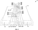
- FIG. 2 is a conceptual and schematic cross sectional side view of an example collection tube section 12 of spray nozzle distribution pattern testing system 10.
- Collection tube section 12 may include coaxial collection tubes 14, which define respective major axes that may extend substantially parallel to a major axis 16 of spray nozzle distribution pattern testing system 10.
- coaxial collection tubes 14 may be substantially conical in shape (e.g., a portion or all of a cone, such as a truncated cone, a cone terminating on one or both ends in a cylindrical shape, a truncated cone terminating on one or both ends in a cylindrical shape, or the like).
- coaxial collection tubes 14 may be rectangular, pyramidal, or another shape.
- Coaxial collection tubes 14 may be configured to collect at least a portion of material (i.e., fluids and/or particles) sprayed from spray nozzle 48 at a specific radial and/or axial position relative to major axis 16.
- each respective coaxial collection tube of coaxial collection tubes 14 may include a respective first end of first ends first ends 18 defining a respective orifice of orifices 20.
- each respective coaxial collection tube of coaxial collection tubes 14 has a different diameter, and coaxial collection tubes that have smaller diameters are disposed within coaxial collection tubes that have larger diameters, such that, in descending diameter, coaxial collection tubes 14 are disposed radially inward from one another.
- coaxial collection tube 14A may be disposed radially inward from coaxial collection tubes 14B, 14C, and 14D.
- the largest coaxial collection tube of coaxial collection tubes 14 is not disposed radially inward any of the other coaxial collection tubes 14.
- coaxial collection tube 14D is not disposed radially inward from coaxial collection tubes 14A, 14B, and 14C.
- each orifice of orifices 20 may include a circular area (e.g., orifice 20A) or an annular area (e.g. orifices 20B, 20C, 20D) defined by concentric coaxial collection tubes 14 or adjacent coaxial collection tubes 14. In this way, each orifice of orifices 20 may correspond to a spray nozzle material collection area.
- orifices 20 may be divided into smaller sections, such as two or more arcs or pie shapes.
- each annular orifice (orifices 20B, 20C, and 20D) shown in FIG. 3 may be divided into two or more arcs, where each arc defines a respective orifice fluidically coupled to a respective collection tube.
- the spray nozzle distribution pattern may be further divided so that the spray material distribution may be evaluate as a function of angle about major axis 16, in addition to as a function of radial distance from major axis 16.
- collection tube section 12 may be configured to collect at least a portion of material sprayed at a respective radial and, optionally, angular, position.
- each of first ends 18 of coaxial collection tubes 14 may be disposed at a respective first position of first positions 22A-22D (collectively, "first positions 22") substantially on a plane (on the plane or nearly on the plane) that is substantially orthogonal (orthogonal or nearly orthogonal) to major axis 16.
- first positions 22 may be on the plane within manufacturing tolerances of system 10.
- a spray nozzle distribution pattern testing system 10 may be used to determine mass distribution, particle size distribution, composition distribution, or the like of spray nozzle 48 as a function of spray nozzle distance from the common plane.
- first ends 18 may be disposed on different planes.
- first ends 18 may be disposed on different planes to resemble the surface geometry of the melt pool and to determine mass distribution, particle size distribution, composition distribution, or the like of spray nozzle 48 as a function of spray nozzle distance from the melt pool.
- a respective collection tube wall of collection tube walls 28A-28D may extend from a respective first end of first ends 18 to a respective second end of second ends 24.
- Collection tube walls 28 may define respective first diameters at first ends 18 and respective second diameters at second ends 24.
- the respective first and second diameters of collection tube walls 28 may be selected to reduce collision of material sprayed from spray nozzle 48 with collection tube walls 28. For example, selection of a first diameter less than a second diameter may reduce collision of material sprayed from spray nozzle 48 with a generally diverging spray nozzle spray pattern (i.e., as viewed outward from spray nozzle 48).
- each respective first diameter may be less than the respective second diameter.
- each respective collection tube wall of collection tube walls 28 extending in a direction from second ends 24 toward first ends 20 may taper toward major axis 16 at a respective angle of angles 30A-30D (collectively, "angles 30"), which may be between 0 and 90 degrees.
- the respective first diameter may be substantially the same as the respective second diameter.
- collection tube walls 28 may not taper, i.e., tube walls 24 extending in a direction from second ends 24 toward first ends 20 may be substantially parallel to major axis 16 and angles 30 may be substantially equal to (e.g., equal to or nearly equal to) 90 degrees.
- the first diameter may be greater than the second diameter.
- collection tube walls 28 extending in a direction from second ends 24 toward first ends 20 may taper away from major axis 16 and angles 30 may be greater than 90 degrees (e.g., between 90 and 180 degrees).
- angles 30 may be the same or different. For instance, in the example shown in FIG. 2 , angle 30D is greater than angle 30C, which is greater than angle 30B, which is greater than angle 30B.
- angles 30 may be selected based on an expected or predicted spray nozzle distribution pattern. For example, angles 30 may be selected to reduce collision of material sprayed from spray nozzle 48 with collection tube walls 28. As another example, angles 30 may reduce backpressure from a gas flow from spray nozzle 48 inside coaxial collection tubes 14. As another example, angles 30 may be substantially the same angle of the spray nozzle distribution pattern at a respective radial distance from major axis 16 to reduce friction between a material stream from spray nozzle 48 and collection tube walls 28, reduce a direction change of a material stream entering coaxial collection tubes 14, reduce a constriction of a material stream entering coaxial collection tubes 14, or the like.
- spray nozzle 48 may output a relatively narrow spray nozzle distribution pattern, e.g., a spatial distribution of powder that diverges from a major axis normal to the spray nozzle tip at an angle less than about 15 degrees, such that angles 30 may be between about 98 degrees and about 80 degrees.
- spray nozzle 48 may output a wide spray nozzle distribution pattern, e.g., a spatial distribution of powder that diverges from the major axis at an angle greater than about 45 degrees, such that angles 30 may be between about 80 degrees and about 40 degrees.
- angles 30 may be between about 97 degrees and about 75 degrees, or between about 92 degrees and about 50 degrees.
- collection tube section 12 may include coaxial collection tube housing 32. In other examples, collection tube section 12 may not include coaxial collection tube housing 32.
- coaxial collection tubes 14 may be disposed inside collection tube housing 32. In some examples collection tube housing 32 may be conical in shape. In other examples, collection tube housing 32 may be rectangular, pyramidal, or another shape. Collection tube housing 32 may be configured to collect material (i.e., fluids and/or particles) sprayed from spray nozzle 48 at a radial position outside of coaxial collection tubes 14, provide mechanical support for coaxial collection tubes 14, provide a connection point for collection tube section 12 to outlet tube section 40, or the like.
- collection tube section 12 may optionally include a plurality of coaxial collection tube supports 34B-34D (collectively, "coaxial collection tube supports 34").
- Coaxial collection tube supports 34 may be disposed between adjacent coaxial collection tubes 14.
- one or more coaxial collection tube supports 34 may be disposed between each pair of adjacent coaxial collection tubes 14.
- four coaxial collection tube supports 34 may be disposed between each pair of adjacent coaxial collection tubes 14.
- coaxial collection tube supports 34 may support one or more coaxial collection tubes 14.
- coaxial collection tube supports 34 may support a respective coaxial collection tube of coaxial collection tubes 14 at a respective first position of first positions 22 (e.g., hold coaxial collection tubes 14 on a common plane).
- coaxial collection tube supports 34 may maintain a spacing between adjacent coaxial collection tubes 14.
- coaxial collection tube supports 34 may maintain a size and shape of a respective orifice of orifices 20 at a respective first position of first positions 22.
- collection tube section 12 may include collection tube housing supports 36.
- collection tube housing supports 36 may support coaxial collection tubes 14 within coaxial collection tube housing 32.
- collection tube housing supports 36 may support coaxial collection tubes 14 at first positions 22 (e.g., hold coaxial collection tubes 14 on a common plane).
- collection tube housing supports 36 may maintain a spacing between collection tube housing 32 and an adjacent coaxial collection tube 14D.
- one or more collection tube housing supports 36 may be disposed between collection tube housing 32 and an adjacent coaxial collection tube 14D.
- four collection tube housing supports 36 may be disposed between collection tube housing 32 and adjacent coaxial collection tube 14D.
- coaxial collection tube supports 34 or collection tube housing supports 36 may be shaped to reduce collection of solid material (e.g., powder) on an outer surface of coaxial collection tube supports 34 or an outer surface of collection tube housing supports 36.
- the outer circumferential surface (i.e., cross sectional shape) of coaxial collection tube supports 34 or collection tube housing supports 36 may be shaped as a rectangular prism, a teardrop, a triangular prism, or the like.
- coaxial collection tube supports 34 or collection tube housing supports 36 shaped as a teardrop or a triangular prism may be oriented such that a point or vertex of the teardrop or the triangular prism is disposed in a plane parallel to the major axis and where the point or vertex is oriented toward orifices 20 of the respective coaxial collection tubes 14.
- spray nozzle distribution pattern testing system 10 includes tube supports 34 or collection tube housing supports 36 shaped as a teardrop or a triangular prism and oriented such that a point or vertex of the teardrop or the triangular prism is disposed in a plane parallel to the major axis where the point or vertex is oriented toward orifices 20 of the respective coaxial collection tubes 14, during use of spray nozzle distribution pattern testing system 10, material may be less likely to adhere to or otherwise collect on the outer surface of tube supports 34 or collection tube housing supports 36 oriented toward orifices 20 such that material collection on the outer surface of tube supports 34 or collection tube housing supports 36 may be reduced.
- coaxial collection tube supports 34 or collection tube housing supports 36 shaped as a rectangular prism may be oriented such that a first side that is substantially smaller than a second side disposed in a plane parallel to the major axis and where the first side is oriented toward orifices 20 of the respective coaxial collection tubes 14.
- spray nozzle distribution pattern testing system 10 includes tube supports 34 or collection tube housing supports 36 shaped as rectangular prism and oriented such that the first side is oriented toward orifices 20 of the respective coaxial collection tubes 14, during use of spray nozzle distribution pattern testing system 10, material may be less likely to adhere to or otherwise collect on the outer surface of tube supports 34 or collection tube housing supports 36 oriented toward orifices 20 such that material collection on the outer surface of tube supports 34 or collection tube housing supports 36 may be reduced.
- collection tube section 12 may collect at least a portion of material sprayed from spray nozzle 48 corresponding to a radial and/or axial position of a spray nozzle distribution pattern, while reducing material collection on collection tube walls 28 or coaxial collection tube supports 34.
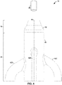
- FIGS. 4 and 6 are conceptual and schematic side views of spray nozzle distribution pattern testing system 10. (The view of FIG. 4 , as compared to FIG. 6 , is rotated approximately 90 degrees about major axis 16.) FIG. 4 also illustrates spray nozzle 48 positioned at a predetermined distance from coaxial collection section 12 of spray nozzle distribution pattern testing system 10.
- outlet tube section 40 may include outlet tubes 42 and outlet tube housing 44.
- outlet tubes 42 may extend through at least a portion of outlet tube housing 44.
- outlet tubes 42 may be positioned substantially equally about major axis 16.
- spray nozzle distribution pattern testing system 10 includes four coaxial collection tubes 14 and four outlet tubes 42.
- outlet tubes 42 may be disposed with a spacing of about 90 degrees relative to adjacent outlet tubes 42 about major axis 16.
- the portion of a respective outlet tube of outlet tubes 42 extending through outlet tube housing 44 may be disposed about 90 degrees relative to each adjacent outlet tube of outlet tubes 42.
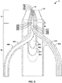
- FIGS. 5 and 7 are conceptual and schematic cross-sections of the side views of FIGS. 4 and 6 , respectively.
- a respective second end of second ends 24 of each respective coaxial collection tube may be coupled to a respective outlet tube of outlet tubes 42.
- each outlet tube of outlet tubes 42 may include a respective outlet tube wall of outlet tube walls 46A-46D (collectively, "outlet tube walls 46").
- a first outlet tube wall 46A of first outlet tube 42A coupled to a first coaxial collection tube 14A may extend through one or more outlet tube walls 46 having a larger diameter than the first outlet tube wall 46A.
- outlet tube wall 46B of outlet tube 42B coupled to coaxial collection tube 14B may extend through outlet tube walls 46C and 46D
- outlet tube wall 46C of outlet tube 42C coupled to coaxial collection tube 14C may extend through outlet tube wall 46D.
- outlet tube wall 46C of outlet tube 42C coupled to coaxial collection tube 14C may extend through outlet tube wall 46D.
- outlet tube wall 46D of outlet tube 42D fluidically coupled to coaxial collection tube 14D may not extend through any other outlet tube walls 46.
- one or more of outlet tube walls 46 may extend through outlet tube housing 44.
- each of outlet tubes walls 46 extends through outlet tube housing 44. In this way, each respective outlet tube of outlet tubes 42 may receive a respective portion of the sprayed material collected by a corresponding orifice of orifices 20 to which the respective cavity of the respective outlet tube is fluidically coupled.
- a shape of outlet tube walls 46 may be configured to reduce accumulation of material (e.g. powder) on the outer surface of outlet tube walls 46.
- outlet tube walls 46 outer circumferential surface i.e., cross sectional shape
- outlet tube walls 46 shaped as a teardrop or a triangular prism may be oriented such that a point or vertex of the teardrop or the triangular prism is disposed in a plane parallel to the major axis and where the point or vertex is oriented toward orifices 20 of the respective coaxial collection tubes 14.
- spray nozzle distribution pattern testing system 10 includes outlet tube walls 46 shaped as a teardrop or a triangular prism, oriented such that a point or vertex of the teardrop or the triangular prism is disposed in a plane parallel to the major axis and where the point or vertex is oriented toward orifices 20 of the respective coaxial collection tubes 14, during use of spray nozzle distribution pattern testing system 10, material may not substantially adhere to outer surfaces of outlet tube walls 46 oriented toward orifices 20 such that material collection on an outer surface of outlet tube walls 46 may be reduced.
- each respective outlet tube of outlet tubes 42 may collect and route material corresponding to a radial and/or axial position of a spray nozzle distribution pattern, while reducing collection of material on outlet tube walls 46.
- a respective outlet tube of outlet tubes 42 may be coupled to a respective receptacle of 52.
- outlet tubes 42 may not be coupled to receptacles 52.
- outlet tube housing 44 may be fluidically coupled to receptacle housing 54.
- receptacles 52 and/or receptacle housing 54 may be configured to collect solid particles.
- receptacles 52 and/or receptacle housing 54 may include outlet ports 56 and outlet port 58, respectively.
- outlet ports 56 and/or outlet port 58 may include a mesh screen, filter, or the like to allow gases to escape the respective receptacle while retaining solid particles inside the respective receptacle.
- each respective receptacle of receptacles 52 may collect material corresponding to a radial and/or axial position of a spray nozzle distribution pattern, while reducing material loss through outlet ports 56 or outlet port 58.
- Material collected in each respective receptacle of receptacles 52 and receptacle housing 54 may be separately analyzed to determine a weight distribution and/or a particle size distribution.
- the weight distribution and/or particle size distribution may be used to determine a spray nozzle distribution pattern as a function of radial position, axial position, distance of spray nozzle 48 from the common plane, or any combination thereof.
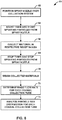
- FIG. 8 is a flow diagram 60 illustrating an example technique for spray nozzle distribution pattern testing.
- the technique of FIG. 8 may include positioning spray nozzle 48 to spray material into at least some of orifices 20 of spray nozzle distribution pattern testing system 10 (62).
- spray nozzle 48 may be positioned at a selected distance from a common plane (e.g., first position 22) of spray nozzle distribution pattern testing system 10.
- the spray nozzle distribution pattern may be a function of radial position, angular position, and axial distance from spray nozzle 48.
- the spray nozzle distribution pattern changes (e.g., expands or contracts) as a function of axial distance from spray nozzle 48.
- spray nozzle distribution pattern testing system 10 may be used to test a single spray nozzle 48 multiple times, each time at a different distance between the outlet of spray nozzle 48 and orifices 20 of spray nozzle distribution pattern testing system 10. This may allow determination of the spray nozzle distribution pattern in three dimensions, e.g., as a function of axial distance from spray nozzle 48, radial position, and, optionally, angular position about major axis 16.
- the spraying process may be started (64).
- the duration of spraying may be timed with a timer, and the timer may be started at a selected time, e.g., when spraying is started or when receptacles 52 are coupled to outlet tubes 42. Measurement of the duration of spraying may allow to determining a mass flow rate of material as the quotient of mass collected over time.
- material e.g., powder
- coaxial collection tubes 14 may be routed into respective outlet tubes 42, and may be collected in respective receptacles 52 (66).
- the spraying process and timer may be stopped (68).
- Material collected in each respective receptacle of receptacles 52 may be weighed, e.g., using a mass balance or a scale (70). The weight of material collected in each respective receptacle 52 may be used to determine a mass distribution of material.
- a material mass flow rate for a respective radial distance of a respective coaxial collection tubes 14 may be determined from the weight of material in each respective receptacle of receptacles 52 and the duration of spraying (72).
- material collected in each respective receptacle of receptacles 52 may be analyzed to determine a particle size distribution for a respective radial distance of a respective coaxial collection tubes 14.
- a particle size distribution for a respective radial distance of a respective coaxial collection tubes 14 may be determined by sieve analysis, air elutriation analysis, or the like.
- a particle size distribution for a respective radial distance of a respective coaxial collection tubes 14 may be determined in situ, e.g., as particles travel through outlet tubes 42 or receptacles 52.
- a particle size distribution for a respective radial distance of a respective coaxial collection tubes 14 may be determined by photoanalysis (e.g., optical granulometry), laser diffraction, or the like.
- a weight distribution, particle size distribution, or combination thereof may be used to characterize a spray nozzle distribution pattern as a function of radial position and distance of a spray nozzle from the common plane.
Landscapes
- Engineering & Computer Science (AREA)
- Chemical & Material Sciences (AREA)
- Manufacturing & Machinery (AREA)
- Materials Engineering (AREA)
- Physics & Mathematics (AREA)
- General Physics & Mathematics (AREA)
- Mechanical Engineering (AREA)
- Processes Of Treating Macromolecular Substances (AREA)
- Sampling And Sample Adjustment (AREA)
Abstract
Description
- The present disclosure generally relates to systems and techniques for testing spray nozzle distribution patterns.
- Additive manufacturing, for example, directed energy deposition techniques, may be used to fabricate a component having a predetermined three-dimensional structure, typically by depositing material layer-by-layer or volume-by-volume to form the structure, rather than by removing material from an existing component. Additive manufacturing may be advantageous in many situations, such as rapid prototyping, forming components with complex three-dimensional structures, or the like.
- According to a first aspect there is provided apparatus comprising: a plurality of coaxial collection tubes extending substantially parallel to a major axis, wherein each tube of the plurality of coaxial collection tubes comprises: a first end defining an orifice, wherein the first end is disposed at a first position on a plane substantially orthogonal to the major axis, a second end coupled to an end of a respective outlet tube of a plurality of outlet tubes, and a collection tube wall extending from the first end to the second end, wherein the collection tube wall at the first end comprises a first diameter, wherein the collection tube wall at a second position between the first end and the second end comprises a second diameter greater than the first diameter, wherein the collection tube wall extending from the second position to the first position tapers toward the major axis at a first angle.
- The respective outlet tube of the plurality of outlet tubes may be fluidically coupled to a respective receptacle of a plurality of receptacles.
- Each of the plurality of receptacles may be configured to collect solid particles.
- The first angle of each respective coaxial collection tube of the plurality of coaxial collection tubes may be based on the second diameter and the first diameter and a spray cone or a spray pattern of a spray nozzle.
- The first angle of each respective tube of the plurality of coaxial collection tubes may reduce the collision of solid particles sprayed from a spray nozzle with the collection tube wall of each respective coaxial collection tube of the plurality of coaxial collection tubes.
- The first angle of each respective coaxial collection tube of the plurality of coaxial collection tubes may reduce gas flow back pressure in each respective coaxial collection tube of the plurality of coaxial collection tubes.
- A first coaxial collection tube of the plurality of coaxial collection tubes may be disposed radially inward from a second coaxial collection tube of the plurality of coaxial collection tubes. A first outlet tube wall of the plurality of outlet tubes fluidically coupled to the first coaxial collection tube may extend through a second outlet tube wall of the plurality of outlet tubes fluidically coupled to the second coaxial collection tube.
- The first outlet tube wall shape may reduce accumulation of particles on the outer surface of the first outlet tube wall.
- The first outlet tube wall may be shaped as a teardrop or a triangular prism. A point or vertex of the teardrop or the triangular prism may be disposed in a plane parallel to the major axis. The point or vertex may be oriented toward the orifice of the respective coaxial collection tubes of the plurality of coaxial collection tubes.
- According to a second aspect there is provided a method of collecting particles from a stream of sprayed particles, the method comprising: positioning a spray nozzle over a collection apparatus at a first distance, wherein the collection apparatus comprises: a plurality of coaxial collection tubes extending substantially parallel to a major axis, wherein each tube of the plurality of coaxial collection tubes comprises: a first end defining an orifice, wherein the first end is disposed at a first position on a plane substantially orthogonal to the major axis, a second end coupled to an end of a respective outlet tube of a plurality of outlet tubes, a collection tube wall extending from the first end to the second end, wherein the collection tube wall at the first end comprises a first diameter, wherein the collection tube wall at a second position between the first end and the second end comprises a second diameter greater than the first diameter, wherein the tube body extending from the second position to the first position tapers toward the major axis at a first angle; collecting particles sprayed from the spray nozzle with the collection apparatus.
- The first distance may be based on a spray pattern of the spray nozzle.
- The outer diameter of a spray cone of a spray nozzle at the first distance may be substantially equal to the outer diameter of at least one coaxial collection tube of the plurality of coaxial collection tubes.
- The method may further comprise: weighing the particles collected from each tube of the plurality of coaxial collection tubes; and determining a mass flow distribution of the spray nozzle based on the weight of particles collected from each tube of the plurality of coaxial collection tubes.
- The particles may be solid particles.
- The method may further comprise: determining a solid particle size distribution of the solid particles collected from each tube of the plurality of coaxial collection tubes.
- The respective outlet tube of the plurality of outlet tubes may be fluidically coupled to a respective receptacle of a plurality of receptacles.
- The first angle of each respective tube of the plurality of coaxial collection tubes may be based on the second diameter and the first diameter and a spray pattern of a spray nozzle.
- The first angle of each respective tube of the plurality of coaxial collection tubes may reduce collision of solid particles sprayed from a spray nozzle with the collection tube wall of each respective tube of the plurality of coaxial collection tubes or may reduce gas flow back pressure in each respective tube of the plurality of coaxial collection tubes.
- A first coaxial collection tube of the plurality of coaxial collection tubes may be disposed radially inward from a second coaxial collection tube of the plurality of coaxial collection tubes. A first outlet tube wall of the plurality of outlet tubes fluidically coupled to the first coaxial collection tube may extend through a second outlet tube wall of the plurality of outlet tubes fluidically coupled to the second coaxial collection tube.
- The first outlet tube wall shape may reduce accumulation of particles on the outer surface of the first outlet tube wall.
- In some examples, the disclosure describes an example system that includes a plurality of coaxial collection tubes extending substantially parallel to a major axis. Each tube of the plurality of coaxial collection tubes includes a first end defining an orifice, where the first end is disposed at a first position on a plane substantially orthogonal to the major axis; a second end coupled to an end of a respective outlet tube of a plurality of outlet tubes; and a collection tube wall extending from the first end to the second end, where the collection tube wall at the first end has a first diameter and the collection tube wall at a second position between the first end and the second end has a second diameter greater than the first diameter such that the collection tube wall extending from the second position to the first position tapers toward the major axis at a first angle.
- In some examples, the disclosure describes an example technique of collecting particles from a stream of sprayed particles that includes positioning a spray nozzle over a collection apparatus at a first distance and collecting particles sprayed from the spray nozzle with the collection apparatus. The collection apparatus includes a plurality of coaxial collection tubes extending substantially parallel to a major axis. Each tube of the plurality of coaxial collection tubes includes a first end defining an orifice, where the first end is disposed at a first position on a plane substantially orthogonal to the major axis; a second end coupled to an end of a respective outlet tube of a plurality of outlet tubes; and a collection tube wall extending from the first end to the second end, where the collection tube wall at the first end has a first diameter and the collection tube wall at a second position between the first end and the second end has a second diameter greater than the first diameter such that the collection tube wall extending from the second position to the first position tapers toward the major axis at a first angle.
- The details of one or more examples are set forth in the accompanying drawings and the description below. Other features, objects, and advantages will be apparent from the description and drawings, and from the claims.
-
-
FIG. 1 is a conceptual and schematic partially exploded perspective view illustrating an example spray nozzle distribution pattern testing system. -
FIG. 2 is a conceptual and schematic cross sectional side view of an example collection tube section of an example spray nozzle distribution pattern testing system. -
FIG. 3 is a conceptual and schematic plan view of an example collection tube section. -
FIG. 4 is a conceptual and schematic side view of an example spray nozzle distribution pattern testing system. -
FIG. 5 is a conceptual and schematic cross-section of the side view ofFIG. 4 . -
FIG. 6 is a conceptual and schematic side view of an example spray nozzle distribution pattern testing system. -
FIG. 7 is a conceptual and schematic cross-section of the side view ofFIG. 6 . -
FIG. 8 is a flow diagram illustrating an example technique for spray nozzle distribution pattern testing. - The disclosure describes example systems and techniques for testing spray nozzle distribution patterns. Such systems and techniques may be used, for example, to test blown powder direct energy deposition ("DED") spray nozzle distribution patterns. DED systems typically deposit successive layers or volumes of material along a build direction based on a digital representation of a component. Example techniques for DED may include directing an energy beam at a region of a substrate of a component to form an advancing molten pool and delivering material from a spray nozzle to a target delivery region in or around the advancing molten pool, resulting in combining of the material and the substrate by sintering or melting, to form a deposited volume of a plurality of deposited volumes. The plurality of deposited volumes may define the component.
- Blown powder DED may use material that includes powder of selected particle size and composition that is blown at or adjacent to the melt pool. During the deposition, the spatial distribution of the powder (referred to herein as the spray nozzle distribution pattern) may determine the actual delivery region in which powder is delivered. The spray nozzle distribution pattern may include, for example, powder size distribution as a function of position within the powder spray, powder weight or density as a function of position within the powder spray, gas flow rate as a function of position within the powder spray, and powder flow rate as a function of position within the powder spray. When the actual delivery region is not substantially similar to the target delivery region, i.e., in or around the advancing molten pool, deposition defects may occur. For example, powder may be left partially or fully unmelted, or otherwise unincorporated in the melt pool, or less powder than intended may be incorporated in the melt pool, leading to smaller than intended material addition. In either case, deviation from an expected amount of powder incorporation may lead to defects in the formed component, such as voids, inclusions, unwanted material phases or microstructures, poor cohesion, chambers that include residual, unjoined material, unintended vibration frequencies during operation of the component, blocked channels or openings, audible sound such as rustling or rattling during use, or the like.
- In accordance with examples of this disclosure, an example system that includes multiple, concentric and coaxial collection tubes may be used to test spray nozzles to determine a spray nozzle distribution pattern. For example, the example system may include several coaxial collection tubes extending substantially parallel to a major axis, each coaxial collection tube including a first end and a second end. Each first end may define an orifice, and may be disposed at a first position on a common plane that is substantially orthogonal to the major axis. Each second end may be coupled to an end of a respective outlet tube of a plurality of outlet tubes. Each of the coaxial collection tubes may taper from a larger diameter to a smaller diameter near the first end.
- In use of the system, a spray nozzle may be positioned to spray material into at least some of the orifices. The spray nozzle may be positioned at a selected distance from the common plane. The material that is blown into the coaxial collection tubes is routed into the respective outlet tubes. Each respective outlet tube may be fluidically connected to a respective receptacle. Material collected in each respective receptacle may be analyzed separately for weight distribution, particle size distribution, composition, or the like, allowing for direct measurement of spray nozzle distribution pattern as a function of radial position and spray nozzle distance from the common plane. For example, the systems and techniques described herein may allow measurement of particle size, material flow rate, material composition, and the like as a function of radial position and distance of the spray nozzle from the common plane. Thus, in accordance with examples of this disclosure, systems and techniques are provided to determine a spray nozzle distribution pattern by direct measurements of the material sprayed.
-
FIGS. 1-7 are conceptual and schematic diagrams illustrating different views of an example spray nozzle distributionpattern testing system 10 or sections thereof. InFIGS. 1-7 , like reference numeral refer to like structures. -
FIG. 1 is a conceptual and schematic partially exploded perspective view illustrating an example spray nozzle distributionpattern testing system 10. In some examples, spray nozzle distributionpattern testing system 10 may includecollection tube section 12,outlet tube section 40, andreceptacle section 50. -
Collection tube section 12 may include a plurality ofcoaxial collection tubes 14A-14D (collectively, "coaxial collection tubes 14") each including a respective first end of first ends 18A-18D (collectively, "first ends 18disposed on a common plane, and a respective second end of second ends 24A-24D (collectively, "second ends 24").Collection tube section 12 also may optionally include acollection tube housing 32. During use of spray nozzle distributionpattern testing system 10, a spray nozzle 48 (FIG. 4 ) may be positioned a selected distance from orifices 20 to spray material into at least some of the orifices 20. In this way,collection tube section 12 may collect at least a portion of material sprayed fromspray nozzle 48. - As each respective coaxial collection tube of coaxial collection tubes 14 is sized differently such that each has a different circumference and diameter at the common plane,
orifices 20A-20D (collectively, "orifices 20") are defined by walls of coaxial collection tubes 14. Each orifice of orifices 20 provides an entry for material (e.g., blown powder) into spray nozzle distributionpattern testing system 10. -
Outlet tube section 40 may include a plurality ofoutlet tubes 42A-42D (collectively, "outlet tubes 42") and optionally may include anoutlet tube housing 44. A first end of each respective outlet tube of outlet tubes 42 may be coupled to a respective second end of second ends 24. Also, a first end ofoutlet tube housing 44 may be attached to an end ofcollection tube housing 32. During use of spray nozzle distributionpattern testing system 10, material that is blown into the coaxial collection tubes 14 may be routed into a respective outlet tubes of outlet tubes 42. For example, at the locations at which the respective outlet tubes 42 are attached to respective second ends 24. In this way,outlet tube section 40 may collect and route material corresponding to a radial and/or axial position of a spray nozzle distribution pattern. -
Receptacle section 50 may include a plurality ofreceptacles 52A-52D (collectively, "receptacles 52") and areceptacle housing 54. Receptacles 52 each may include a respective gas outlet port of a plurality ofgas outlet ports 56A-56D (collectively, "gas outlet ports 56"), andreceptacle housing 54 may include an optionalgas outlet port 58. Each respective receptacle of receptacles 52 may be fluidically coupled to a respective outlet tube of outlet tubes 42. Also,receptacle housing 54 may be fluidically coupled tooutlet tube housing 44. During use of spray nozzle distributionpattern testing system 10, material that is routed into a respective outlet tube of outlet tubes 42 may be collected in a respective receptacle of receptacles 52 and gas may exit a respective receptacle of receptacles 52 via a respective gas outlet port 56. In this way,receptacle section 50 may collect material corresponding to a radial and/or axial position of a spray nozzle distribution pattern. In some examples, material received in an orifice between anouter collection tube 14D of collection tubes 14 andcollection tube housing 32 may be collected in receptacle housing. - Material collected in each respective receptacle of receptacles 52 and
receptacle housing 54 via spray nozzle distributionpattern testing system 10 may be separately analyzed to determine a weight distribution, a particle size distribution, composition distribution, or the like. For example, each receptacle of receptacles 52 may collect material or powder from a respective annular area corresponding to each of orifices 20. The weight distribution and/or particle size distribution may be used to determine a spray nozzle distribution pattern as a function of radial position, spray nozzle distance from the common plane, or any combination thereof. For example, spray nozzle distributionpattern testing system 10 may allow measurement of material size, material flow rate, material composition, and the like as a function of radial position and distance ofspray nozzle 48 from the common plane. Thus, spray nozzle distributionpattern testing system 10 may be used to determine a spray nozzle distribution pattern by direct measurements of the material sprayed. - Each component (e.g.,
collection tube section 12,outlet tube section 40, and receptacle section 50) of spray nozzle distributionpattern testing system 10 may be formed from any suitable material. For example, spray nozzle distributionpattern testing system 10 may be formed from a plastic (e.g., acrylonitrile butadiene styrene, polylactic acid, polyethylene terephthalate, high-density polyethylene, polyvinyl chloride, polymethyl methacrylate, or the like), an electrically conductive plastic, a static dissipative plastic, a metal (e.g., aluminum, brass, bronze, copper, steel, or the like), an alloy, a combination of both a plastic and a metal, or the like.Collection tube section 12,outlet tube section 40, andreceptacle section 50 may be formed of similar or different materials. For example,collection tube 12 may be formed from a metal,outlet tube section 40 may be formed from a plastic, andreceptacle section 50 may be formed from a plastic. In some examples, any one or more ofcollection tube section 12,outlet tube section 40,receptacle section 50, or one or more of components thereof may be formed using directed energy deposition. -
FIG. 2 is a conceptual and schematic cross sectional side view of an examplecollection tube section 12 of spray nozzle distributionpattern testing system 10.Collection tube section 12 may include coaxial collection tubes 14, which define respective major axes that may extend substantially parallel to amajor axis 16 of spray nozzle distributionpattern testing system 10. In some examples, coaxial collection tubes 14 may be substantially conical in shape (e.g., a portion or all of a cone, such as a truncated cone, a cone terminating on one or both ends in a cylindrical shape, a truncated cone terminating on one or both ends in a cylindrical shape, or the like). In other examples, coaxial collection tubes 14 may be rectangular, pyramidal, or another shape. Coaxial collection tubes 14 may be configured to collect at least a portion of material (i.e., fluids and/or particles) sprayed fromspray nozzle 48 at a specific radial and/or axial position relative tomajor axis 16. - As best seen in
FIG. 3 , which is a conceptual and schematic plan view ofcollection tube section 12, each respective coaxial collection tube of coaxial collection tubes 14 may include a respective first end of first ends first ends 18 defining a respective orifice of orifices 20. As the collection tubes are coaxial, each respective coaxial collection tube of coaxial collection tubes 14 has a different diameter, and coaxial collection tubes that have smaller diameters are disposed within coaxial collection tubes that have larger diameters, such that, in descending diameter, coaxial collection tubes 14 are disposed radially inward from one another. For example,coaxial collection tube 14A may be disposed radially inward fromcoaxial collection tubes coaxial collection tube 14D is not disposed radially inward fromcoaxial collection tubes - As shown in
FIG. 3 , in some examples, each orifice of orifices 20 may include a circular area (e.g.,orifice 20A) or an annular area (e.g. orifices - In other examples, orifices 20 may be divided into smaller sections, such as two or more arcs or pie shapes. For example, each annular orifice (
orifices FIG. 3 may be divided into two or more arcs, where each arc defines a respective orifice fluidically coupled to a respective collection tube. By dividing orifices 20 into multiple arc or pie shapes, the spray nozzle distribution pattern may be further divided so that the spray material distribution may be evaluate as a function of angle aboutmajor axis 16, in addition to as a function of radial distance frommajor axis 16. In this way,collection tube section 12 may be configured to collect at least a portion of material sprayed at a respective radial and, optionally, angular, position. - In some examples, as best seen in
FIG. 2 , each of first ends 18 of coaxial collection tubes 14 may be disposed at a respective first position offirst positions 22A-22D (collectively, "first positions 22") substantially on a plane (on the plane or nearly on the plane) that is substantially orthogonal (orthogonal or nearly orthogonal) tomajor axis 16. For example, thefirst positions 22 may be on the plane within manufacturing tolerances ofsystem 10. In some examples in which first ends 18 are disposed substantially on a common plane, a spray nozzle distributionpattern testing system 10 may be used to determine mass distribution, particle size distribution, composition distribution, or the like ofspray nozzle 48 as a function of spray nozzle distance from the common plane. In other examples, first ends 18 may be disposed on different planes. For example, where a surface geometry of a melt pool of a DED process may be nonplanar (e.g., curved), first ends 18 may be disposed on different planes to resemble the surface geometry of the melt pool and to determine mass distribution, particle size distribution, composition distribution, or the like ofspray nozzle 48 as a function of spray nozzle distance from the melt pool. - As best seen in
FIG. 2 , a respective collection tube wall ofcollection tube walls 28A-28D (collectively, "collection tube walls 28") may extend from a respective first end of first ends 18 to a respective second end of second ends 24. Collection tube walls 28 may define respective first diameters at first ends 18 and respective second diameters at second ends 24. In some examples, the respective first and second diameters of collection tube walls 28 may be selected to reduce collision of material sprayed fromspray nozzle 48 with collection tube walls 28. For example, selection of a first diameter less than a second diameter may reduce collision of material sprayed fromspray nozzle 48 with a generally diverging spray nozzle spray pattern (i.e., as viewed outward from spray nozzle 48). Hence, in some examples, for each coaxial collection tube of coaxial collection tubes 14, the respective first diameter may be less than the respective second diameter. As best seen inFIG. 2 , in some examples, each respective collection tube wall of collection tube walls 28 extending in a direction from second ends 24 toward first ends 20 may taper towardmajor axis 16 at a respective angle ofangles 30A-30D (collectively, "angles 30"), which may be between 0 and 90 degrees. - In other examples, for each coaxial collection tube of coaxial collection tubes 14, the respective first diameter may be substantially the same as the respective second diameter. In other words, collection tube walls 28 may not taper, i.e., tube walls 24 extending in a direction from second ends 24 toward first ends 20 may be substantially parallel to
major axis 16 and angles 30 may be substantially equal to (e.g., equal to or nearly equal to) 90 degrees. In other examples, the first diameter may be greater than the second diameter. In other words, collection tube walls 28 extending in a direction from second ends 24 toward first ends 20 may taper away frommajor axis 16 and angles 30 may be greater than 90 degrees (e.g., between 90 and 180 degrees). Regardless of the particular values of angles 30, angles 30 may be the same or different. For instance, in the example shown inFIG. 2 ,angle 30D is greater thanangle 30C, which is greater thanangle 30B, which is greater thanangle 30B. - In some examples, angles 30 may be selected based on an expected or predicted spray nozzle distribution pattern. For example, angles 30 may be selected to reduce collision of material sprayed from
spray nozzle 48 with collection tube walls 28. As another example, angles 30 may reduce backpressure from a gas flow fromspray nozzle 48 inside coaxial collection tubes 14. As another example, angles 30 may be substantially the same angle of the spray nozzle distribution pattern at a respective radial distance frommajor axis 16 to reduce friction between a material stream fromspray nozzle 48 and collection tube walls 28, reduce a direction change of a material stream entering coaxial collection tubes 14, reduce a constriction of a material stream entering coaxial collection tubes 14, or the like. For example,spray nozzle 48 may output a relatively narrow spray nozzle distribution pattern, e.g., a spatial distribution of powder that diverges from a major axis normal to the spray nozzle tip at an angle less than about 15 degrees, such that angles 30 may be between about 98 degrees and about 80 degrees. As another example,spray nozzle 48 may output a wide spray nozzle distribution pattern, e.g., a spatial distribution of powder that diverges from the major axis at an angle greater than about 45 degrees, such that angles 30 may be between about 80 degrees and about 40 degrees. In some examples, angles 30 may be between about 97 degrees and about 75 degrees, or between about 92 degrees and about 50 degrees. - In some examples, as shown in
FIG. 2 ,collection tube section 12 may include coaxialcollection tube housing 32. In other examples,collection tube section 12 may not include coaxialcollection tube housing 32. In some examples, coaxial collection tubes 14 may be disposed insidecollection tube housing 32. In some examplescollection tube housing 32 may be conical in shape. In other examples,collection tube housing 32 may be rectangular, pyramidal, or another shape.Collection tube housing 32 may be configured to collect material (i.e., fluids and/or particles) sprayed fromspray nozzle 48 at a radial position outside of coaxial collection tubes 14, provide mechanical support for coaxial collection tubes 14, provide a connection point forcollection tube section 12 tooutlet tube section 40, or the like. - In some examples, as best seen in
FIG. 2 ,collection tube section 12 may optionally include a plurality of coaxial collection tube supports 34B-34D (collectively, "coaxial collection tube supports 34"). Coaxial collection tube supports 34 may be disposed between adjacent coaxial collection tubes 14. In some examples, one or more coaxial collection tube supports 34 may be disposed between each pair of adjacent coaxial collection tubes 14. For example, four coaxial collection tube supports 34 may be disposed between each pair of adjacent coaxial collection tubes 14. In some examples, coaxial collection tube supports 34 may support one or more coaxial collection tubes 14. For example, coaxial collection tube supports 34 may support a respective coaxial collection tube of coaxial collection tubes 14 at a respective first position of first positions 22 (e.g., hold coaxial collection tubes 14 on a common plane). In some examples, coaxial collection tube supports 34 may maintain a spacing between adjacent coaxial collection tubes 14. For example, coaxial collection tube supports 34 may maintain a size and shape of a respective orifice of orifices 20 at a respective first position offirst positions 22. - In some examples, as best seen in
FIG. 2 ,collection tube section 12 may include collection tube housing supports 36. In some examples, collection tube housing supports 36 may support coaxial collection tubes 14 within coaxialcollection tube housing 32. For example, collection tube housing supports 36 may support coaxial collection tubes 14 at first positions 22 (e.g., hold coaxial collection tubes 14 on a common plane). In some examples, collection tube housing supports 36 may maintain a spacing betweencollection tube housing 32 and an adjacentcoaxial collection tube 14D. In some examples, one or more collection tube housing supports 36 may be disposed betweencollection tube housing 32 and an adjacentcoaxial collection tube 14D. For example, four collection tube housing supports 36 may be disposed betweencollection tube housing 32 and adjacentcoaxial collection tube 14D. - In some examples, one or both of coaxial collection tube supports 34 or collection tube housing supports 36 may be shaped to reduce collection of solid material (e.g., powder) on an outer surface of coaxial collection tube supports 34 or an outer surface of collection tube housing supports 36. For example, the outer circumferential surface (i.e., cross sectional shape) of coaxial collection tube supports 34 or collection tube housing supports 36 may be shaped as a rectangular prism, a teardrop, a triangular prism, or the like.
- In some examples, coaxial collection tube supports 34 or collection tube housing supports 36 shaped as a teardrop or a triangular prism may be oriented such that a point or vertex of the teardrop or the triangular prism is disposed in a plane parallel to the major axis and where the point or vertex is oriented toward orifices 20 of the respective coaxial collection tubes 14. In examples in which spray nozzle distribution
pattern testing system 10 includes tube supports 34 or collection tube housing supports 36 shaped as a teardrop or a triangular prism and oriented such that a point or vertex of the teardrop or the triangular prism is disposed in a plane parallel to the major axis where the point or vertex is oriented toward orifices 20 of the respective coaxial collection tubes 14, during use of spray nozzle distributionpattern testing system 10, material may be less likely to adhere to or otherwise collect on the outer surface of tube supports 34 or collection tube housing supports 36 oriented toward orifices 20 such that material collection on the outer surface of tube supports 34 or collection tube housing supports 36 may be reduced. - In some examples, coaxial collection tube supports 34 or collection tube housing supports 36 shaped as a rectangular prism may be oriented such that a first side that is substantially smaller than a second side disposed in a plane parallel to the major axis and where the first side is oriented toward orifices 20 of the respective coaxial collection tubes 14. In examples in which spray nozzle distribution
pattern testing system 10 includes tube supports 34 or collection tube housing supports 36 shaped as rectangular prism and oriented such that the first side is oriented toward orifices 20 of the respective coaxial collection tubes 14, during use of spray nozzle distributionpattern testing system 10, material may be less likely to adhere to or otherwise collect on the outer surface of tube supports 34 or collection tube housing supports 36 oriented toward orifices 20 such that material collection on the outer surface of tube supports 34 or collection tube housing supports 36 may be reduced. - In this way,
collection tube section 12 may collect at least a portion of material sprayed fromspray nozzle 48 corresponding to a radial and/or axial position of a spray nozzle distribution pattern, while reducing material collection on collection tube walls 28 or coaxial collection tube supports 34. -
FIGS. 4 and6 are conceptual and schematic side views of spray nozzle distributionpattern testing system 10. (The view ofFIG. 4 , as compared toFIG. 6 , is rotated approximately 90 degrees aboutmajor axis 16.)FIG. 4 also illustratesspray nozzle 48 positioned at a predetermined distance fromcoaxial collection section 12 of spray nozzle distributionpattern testing system 10. As shown inFIGS. 4 and6 ,outlet tube section 40 may include outlet tubes 42 andoutlet tube housing 44. In some examples, outlet tubes 42 may extend through at least a portion ofoutlet tube housing 44. In some examples, outlet tubes 42 may be positioned substantially equally aboutmajor axis 16. For example, spray nozzle distributionpattern testing system 10 includes four coaxial collection tubes 14 and four outlet tubes 42. Hence, outlet tubes 42 may be disposed with a spacing of about 90 degrees relative to adjacent outlet tubes 42 aboutmajor axis 16. For example, as shown inFIGS. 4 and6 , the portion of a respective outlet tube of outlet tubes 42 extending throughoutlet tube housing 44 may be disposed about 90 degrees relative to each adjacent outlet tube of outlet tubes 42. -
FIGS. 5 and7 are conceptual and schematic cross-sections of the side views ofFIGS. 4 and6 , respectively. In some examples, as best seen inFIGS. 5 and7 , a respective second end of second ends 24 of each respective coaxial collection tube may be coupled to a respective outlet tube of outlet tubes 42. - In some examples, each outlet tube of outlet tubes 42 may include a respective outlet tube wall of
outlet tube walls 46A-46D (collectively, "outlet tube walls 46"). In some examples, a firstoutlet tube wall 46A offirst outlet tube 42A coupled to a firstcoaxial collection tube 14A may extend through one or more outlet tube walls 46 having a larger diameter than the firstoutlet tube wall 46A. Similarly, as best seen inFIGS. 5 ,outlet tube wall 46B ofoutlet tube 42B coupled tocoaxial collection tube 14B may extend throughoutlet tube walls FIG. 6 ,outlet tube wall 46C ofoutlet tube 42C coupled tocoaxial collection tube 14C may extend throughoutlet tube wall 46D. On the other hand, as best seen inFIG. 6 ,outlet tube wall 46D ofoutlet tube 42D fluidically coupled tocoaxial collection tube 14D may not extend through any other outlet tube walls 46. In some examples, one or more of outlet tube walls 46 may extend throughoutlet tube housing 44. For example, as shown inFIGS. 5 and6 , each of outlet tubes walls 46 extends throughoutlet tube housing 44. In this way, each respective outlet tube of outlet tubes 42 may receive a respective portion of the sprayed material collected by a corresponding orifice of orifices 20 to which the respective cavity of the respective outlet tube is fluidically coupled. - In some examples, a shape of outlet tube walls 46 may be configured to reduce accumulation of material (e.g. powder) on the outer surface of outlet tube walls 46. For example, outlet tube walls 46 outer circumferential surface (i.e., cross sectional shape) may be shaped as a teardrop, a triangular prism, or the like. In some examples, outlet tube walls 46 shaped as a teardrop or a triangular prism may be oriented such that a point or vertex of the teardrop or the triangular prism is disposed in a plane parallel to the major axis and where the point or vertex is oriented toward orifices 20 of the respective coaxial collection tubes 14. In examples in which spray nozzle distribution
pattern testing system 10 includes outlet tube walls 46 shaped as a teardrop or a triangular prism, oriented such that a point or vertex of the teardrop or the triangular prism is disposed in a plane parallel to the major axis and where the point or vertex is oriented toward orifices 20 of the respective coaxial collection tubes 14, during use of spray nozzle distributionpattern testing system 10, material may not substantially adhere to outer surfaces of outlet tube walls 46 oriented toward orifices 20 such that material collection on an outer surface of outlet tube walls 46 may be reduced. - In this way, each respective outlet tube of outlet tubes 42 may collect and route material corresponding to a radial and/or axial position of a spray nozzle distribution pattern, while reducing collection of material on outlet tube walls 46.
- As shown in
FIG. 1 , a respective outlet tube of outlet tubes 42 may be coupled to a respective receptacle of 52. In other examples, outlet tubes 42 may not be coupled to receptacles 52. In some examples,outlet tube housing 44 may be fluidically coupled toreceptacle housing 54. In some examples, receptacles 52 and/orreceptacle housing 54 may be configured to collect solid particles. For example, receptacles 52 and/orreceptacle housing 54 may include outlet ports 56 andoutlet port 58, respectively. In some examples, outlet ports 56 and/oroutlet port 58 may include a mesh screen, filter, or the like to allow gases to escape the respective receptacle while retaining solid particles inside the respective receptacle. - In this way, each respective receptacle of receptacles 52 may collect material corresponding to a radial and/or axial position of a spray nozzle distribution pattern, while reducing material loss through outlet ports 56 or
outlet port 58. - Material collected in each respective receptacle of receptacles 52 and
receptacle housing 54 may be separately analyzed to determine a weight distribution and/or a particle size distribution. The weight distribution and/or particle size distribution may be used to determine a spray nozzle distribution pattern as a function of radial position, axial position, distance ofspray nozzle 48 from the common plane, or any combination thereof. -
FIG. 8 is a flow diagram 60 illustrating an example technique for spray nozzle distribution pattern testing. The technique ofFIG. 8 may include positioningspray nozzle 48 to spray material into at least some of orifices 20 of spray nozzle distribution pattern testing system 10 (62). In some examples,spray nozzle 48 may be positioned at a selected distance from a common plane (e.g., first position 22) of spray nozzle distributionpattern testing system 10. - In some implementations, the spray nozzle distribution pattern may be a function of radial position, angular position, and axial distance from
spray nozzle 48. For example, in implementations in which spraynozzle 48 produces a converging or diverging spray, the spray nozzle distribution pattern changes (e.g., expands or contracts) as a function of axial distance fromspray nozzle 48. Hence, spray nozzle distributionpattern testing system 10 may be used to test asingle spray nozzle 48 multiple times, each time at a different distance between the outlet ofspray nozzle 48 and orifices 20 of spray nozzle distributionpattern testing system 10. This may allow determination of the spray nozzle distribution pattern in three dimensions, e.g., as a function of axial distance fromspray nozzle 48, radial position, and, optionally, angular position aboutmajor axis 16. - Once
spray nozzle 48 is positioned at the selected position, the spraying process may be started (64). In some examples, the duration of spraying may be timed with a timer, and the timer may be started at a selected time, e.g., when spraying is started or when receptacles 52 are coupled to outlet tubes 42. Measurement of the duration of spraying may allow to determining a mass flow rate of material as the quotient of mass collected over time. - During use of spray nozzle distribution
pattern testing system 10, material (e.g., powder) may be blown into coaxial collection tubes 14, may be routed into respective outlet tubes 42, and may be collected in respective receptacles 52 (66). At a selected time, the spraying process and timer may be stopped (68). Material collected in each respective receptacle of receptacles 52 may be weighed, e.g., using a mass balance or a scale (70). The weight of material collected in each respective receptacle 52 may be used to determine a mass distribution of material. In some examples, a material mass flow rate for a respective radial distance of a respective coaxial collection tubes 14 may be determined from the weight of material in each respective receptacle of receptacles 52 and the duration of spraying (72). - In some examples, material collected in each respective receptacle of receptacles 52 may be analyzed to determine a particle size distribution for a respective radial distance of a respective coaxial collection tubes 14. For example, a particle size distribution for a respective radial distance of a respective coaxial collection tubes 14 may be determined by sieve analysis, air elutriation analysis, or the like. In other examples, a particle size distribution for a respective radial distance of a respective coaxial collection tubes 14 may be determined in situ, e.g., as particles travel through outlet tubes 42 or receptacles 52. For example, a particle size distribution for a respective radial distance of a respective coaxial collection tubes 14 may be determined by photoanalysis (e.g., optical granulometry), laser diffraction, or the like. In some examples, a weight distribution, particle size distribution, or combination thereof may be used to characterize a spray nozzle distribution pattern as a function of radial position and distance of a spray nozzle from the common plane.
- Various examples have been described. These and other examples are within the scope of the following claims.
Claims (15)
- An apparatus comprising:a plurality of coaxial collection tubes extending substantially parallel to a major axis,wherein each tube of the plurality of coaxial collection tubes comprises:a first end defining an orifice, wherein the first end is disposed at a first position on a plane substantially orthogonal to the major axis,a second end coupled to an end of a respective outlet tube of a plurality of outlet tubes, anda collection tube wall extending from the first end to the second end,wherein the collection tube wall at the first end comprises a first diameter,wherein the collection tube wall at a second position between the first end and the second end comprises a second diameter greater than the first diameter, wherein the collection tube wall extending from the second position to the first position tapers toward the major axis at a first angle.
- The apparatus of claim 1, wherein the respective outlet tube of the plurality of outlet tubes is fluidically coupled to a respective receptacle of a plurality of receptacles.
- The apparatus of claim 2, wherein each of the plurality of receptacles is configured to collect solid particles.
- The apparatus of any of claims 1 to 3, wherein the first angle of each respective coaxial collection tube of the plurality of coaxial collection tubes is based on the second diameter and the first diameter and a spray cone or a spray pattern of a spray nozzle.
- The apparatus of any of claims 1 to 4, wherein the first angle of each respective tube of the plurality of coaxial collection tubes reduces the collision of solid particles sprayed from a spray nozzle with the collection tube wall of each respective coaxial collection tube of the plurality of coaxial collection tubes.
- The apparatus of any of claims 1 to 5, wherein the first angle of each respective coaxial collection tube of the plurality of coaxial collection tubes reduces gas flow back pressure in each respective coaxial collection tube of the plurality of coaxial collection tubes.
- The apparatus of any of claims 1 to 6, wherein a first coaxial collection tube of the plurality of coaxial collection tubes is disposed radially inward from a second coaxial collection tube of the plurality of coaxial collection tubes, wherein a first outlet tube wall of the plurality of outlet tubes fluidically coupled to the first coaxial collection tube extends through a second outlet tube wall of the plurality of outlet tubes fluidically coupled to the second coaxial collection tube.
- The apparatus of claim 7, wherein the first outlet tube wall shape reduces accumulation of particles on the outer surface of the first outlet tube wall.
- The apparatus of claim 7 or 8, wherein the first outlet tube wall is shaped as a teardrop or a triangular prism, wherein a point or vertex of the teardrop or the triangular prism is disposed in a plane parallel to the major axis, wherein the point or vertex is oriented toward the orifice of the respective coaxial collection tubes of the plurality of coaxial collection tubes.
- A method of collecting particles from a stream of sprayed particles, the method comprising:positioning a spray nozzle over a collection apparatus at a first distance, wherein the collection apparatus comprises:a plurality of coaxial collection tubes extending substantially parallel to a major axis, wherein each tube of the plurality of coaxial collection tubes comprises:a first end defining an orifice, wherein the first end is disposed at a first position on a plane substantially orthogonal to the major axis,a second end coupled to an end of a respective outlet tube of a plurality of outlet tubes,a collection tube wall extending from the first end to the second end, wherein the collection tube wall at the first end comprises a first diameter, wherein the collection tube wall at a second position between the first end and the second end comprises a second diameter greater than the first diameter, wherein the tube body extending from the second position to the first position tapers toward the major axis at a first angle;collecting particles sprayed from the spray nozzle with the collection apparatus.
- The method of claim 10, wherein the first distance is based on a spray pattern of the spray nozzle.
- The method of claim 10 or 11, wherein the outer diameter of a spray cone of a spray nozzle at the first distance is substantially equal to the outer diameter of at least one coaxial collection tube of the plurality of coaxial collection tubes.
- The method of any of claims 10 to 12, further comprising:weighing the particles collected from each tube of the plurality of coaxial collection tubes; anddetermining a mass flow distribution of the spray nozzle based on the weight of particles collected from each tube of the plurality of coaxial collection tubes.
- The method of any one of claims 10 to 13, wherein the particles are solid particles, and wherein the method further comprises: determining a solid particle size distribution of the solid particles collected from each tube of the plurality of coaxial collection tubes.
- The method of any of claims 10 to 14, wherein the first angle of each respective tube of the plurality of coaxial collection tubes reduces collision of solid particles sprayed from a spray nozzle with the collection tube wall of each respective tube of the plurality of coaxial collection tubes or reduces gas flow back pressure in each respective tube of the plurality of coaxial collection tubes.
Applications Claiming Priority (1)
| Application Number | Priority Date | Filing Date | Title |
|---|---|---|---|
| US15/418,209 US10370233B2 (en) | 2017-01-27 | 2017-01-27 | Directed energy deposition spray nozzle distribution pattern testing |
Publications (2)
| Publication Number | Publication Date |
|---|---|
| EP3355044A1 true EP3355044A1 (en) | 2018-08-01 |
| EP3355044B1 EP3355044B1 (en) | 2021-08-04 |
Family
ID=61131924
Family Applications (1)
| Application Number | Title | Priority Date | Filing Date |
|---|---|---|---|
| EP18152106.3A Active EP3355044B1 (en) | 2017-01-27 | 2018-01-17 | Directed energy deposition spray nozzle distribution pattern testing |
Country Status (2)
| Country | Link |
|---|---|
| US (1) | US10370233B2 (en) |
| EP (1) | EP3355044B1 (en) |
Cited By (1)
| Publication number | Priority date | Publication date | Assignee | Title |
|---|---|---|---|---|
| WO2020089174A1 (en) * | 2018-10-29 | 2020-05-07 | Sms Group Gmbh | Mixing body |
Families Citing this family (2)
| Publication number | Priority date | Publication date | Assignee | Title |
|---|---|---|---|---|
| US11612986B2 (en) | 2019-12-17 | 2023-03-28 | Rolls-Royce Corporation | Abrasive coating including metal matrix and ceramic particles |
| WO2022146647A1 (en) * | 2020-12-29 | 2022-07-07 | 3D Systems, Inc. | Branching support for metals that minimizes material usage |
Citations (7)
| Publication number | Priority date | Publication date | Assignee | Title |
|---|---|---|---|---|
| US3459049A (en) * | 1967-12-19 | 1969-08-05 | Us Air Force | Spray pattern measurement |
| JPH11352021A (en) * | 1998-06-05 | 1999-12-24 | Unisia Jecs Corp | Injection valve spray pattern inspection system |
| DE19836961A1 (en) * | 1997-04-18 | 2000-02-24 | Mitsubishi Electric Corp | Spraying distribution measuring device of fuel injection nozzle of IC engine |
| EP1063509A2 (en) * | 1999-06-09 | 2000-12-27 | Air Dispersions Ltd. | Sampling devices |
| EP1837829A1 (en) * | 2006-03-23 | 2007-09-26 | Pratt & Whitney Canada Corp. | Method of computing spray parameters from optical patternation |
| US20070235567A1 (en) * | 2006-04-11 | 2007-10-11 | Cooper William R | Calibrating system for measuring sprayed materials |
| DE102013223443A1 (en) * | 2013-11-18 | 2015-05-21 | Robert Bosch Gmbh | Apparatus and method for determining a beam profile |
Family Cites Families (9)
| Publication number | Priority date | Publication date | Assignee | Title |
|---|---|---|---|---|
| US2483637A (en) | 1941-08-29 | 1949-10-04 | Power Jets Res & Dev Ltd | Means for testing spraying devices |
| US3998097A (en) | 1975-03-17 | 1976-12-21 | Mitsubishi Jukogyo Kabushiki Kaisha | Flow-measuring device |
| US4347742A (en) * | 1980-09-29 | 1982-09-07 | Stepan Chemical Company | Evaluating sprayability |
| JPH0643911B2 (en) | 1985-09-17 | 1994-06-08 | アイ・ティー・エム株式会社 | Gas carrier powder supply system |
| US5753806A (en) | 1996-10-30 | 1998-05-19 | Southwest Research Institute | Apparatus and method for determining the distribution and flow rate characteristics of an injection nozzle |
| DE19650112C1 (en) | 1996-12-03 | 1998-05-20 | Wagner Int | Device and method for measuring a powder mass flow |
| DE19844602A1 (en) | 1998-09-29 | 2000-03-30 | Bosch Gmbh Robert | Method and device for measuring the angular distribution of a liquid jet |
| KR101243338B1 (en) | 2010-10-29 | 2013-03-13 | 한국항공대학교산학협력단 | A device for measuring droplet mass flux distributions to test spray injection system and the measuring method |
| CN102564790A (en) | 2011-12-29 | 2012-07-11 | 北京农业智能装备技术研究中心 | Device and method for measuring spray volume spatial distribution of variable rate spray |
-
2017
- 2017-01-27 US US15/418,209 patent/US10370233B2/en active Active
-
2018
- 2018-01-17 EP EP18152106.3A patent/EP3355044B1/en active Active
Patent Citations (7)
| Publication number | Priority date | Publication date | Assignee | Title |
|---|---|---|---|---|
| US3459049A (en) * | 1967-12-19 | 1969-08-05 | Us Air Force | Spray pattern measurement |
| DE19836961A1 (en) * | 1997-04-18 | 2000-02-24 | Mitsubishi Electric Corp | Spraying distribution measuring device of fuel injection nozzle of IC engine |
| JPH11352021A (en) * | 1998-06-05 | 1999-12-24 | Unisia Jecs Corp | Injection valve spray pattern inspection system |
| EP1063509A2 (en) * | 1999-06-09 | 2000-12-27 | Air Dispersions Ltd. | Sampling devices |
| EP1837829A1 (en) * | 2006-03-23 | 2007-09-26 | Pratt & Whitney Canada Corp. | Method of computing spray parameters from optical patternation |
| US20070235567A1 (en) * | 2006-04-11 | 2007-10-11 | Cooper William R | Calibrating system for measuring sprayed materials |
| DE102013223443A1 (en) * | 2013-11-18 | 2015-05-21 | Robert Bosch Gmbh | Apparatus and method for determining a beam profile |
Cited By (1)
| Publication number | Priority date | Publication date | Assignee | Title |
|---|---|---|---|---|
| WO2020089174A1 (en) * | 2018-10-29 | 2020-05-07 | Sms Group Gmbh | Mixing body |
Also Published As
| Publication number | Publication date |
|---|---|
| US20180215601A1 (en) | 2018-08-02 |
| EP3355044B1 (en) | 2021-08-04 |
| US10370233B2 (en) | 2019-08-06 |
Similar Documents
| Publication | Publication Date | Title |
|---|---|---|
| EP3355044A1 (en) | Directed energy deposition spray nozzle distribution pattern testing | |
| JP7119035B2 (en) | ceramic filter | |
| EP3094411B1 (en) | Particle separator for an additive manufacturing system and method of operation | |
| CN108136500B (en) | Method and device for additive manufacturing of components | |
| JP5330378B2 (en) | Spray nozzle for powder spray gun | |
| Kumar et al. | Critical review of off-axial nozzle and coaxial nozzle for powder metal deposition | |
| US11084209B2 (en) | Extraction during additive manufacturing | |
| EP3213320B1 (en) | Arrangement for transmitting and/or receiving a useful ultrasound signal, and ultrasonic flow meter | |
| US20130086876A1 (en) | Inertial filter and particle classification apparatus | |
| JP2019524483A (en) | Method for additive manufacturing and multipurpose powder removal mechanism | |
| Yan et al. | Design of injection nozzle in direct metal deposition (DMD) manufacturing of thin-walled structures based on 3D models | |
| Yao et al. | Deposition behavior of semi-molten spray particles during flame spraying of porous metal alloy | |
| WO2021058374A1 (en) | Device for atomizing a melt stream by means of a gas | |
| KR20190075927A (en) | APPARATUS AND METHOD FOR FORMING POWDER | |
| Brückner et al. | Surface Functionalization by High‐precision Laser Cladding: Process equipment and manufacturing strategies for miniaturized and customized components | |
| US11976677B2 (en) | Integrally formed flow distributor for fluid manifold | |
| EP3415923A1 (en) | Additively manufactured flow measurement sensor | |
| Wang | High-quality high-material-usage multiple-layer laser deposition of nickel alloys using sonic or ultrasonic vibration powder feeding | |
| US11255339B2 (en) | Fan structure having integrated rotor impeller, and methods of producing the same | |
| US20200139435A1 (en) | Cold spray forming | |
| US20250020497A1 (en) | Measurement apparatus and method | |
| JP7688722B2 (en) | Corrugated passive radio frequency devices suitable for additive manufacturing processes | |
| Zhou et al. | Size distribution of spray atomised aluminium alloy powders produced during linear atomisation | |
| CN110576603A (en) | Method of operating an apparatus for additive manufacturing of three-dimensional objects | |
| Malmberg | Analysis of the plasma jet structure, particle motion, and coating quality during DC plasma spraying |
Legal Events
| Date | Code | Title | Description |
|---|---|---|---|
| PUAI | Public reference made under article 153(3) epc to a published international application that has entered the european phase |
Free format text: ORIGINAL CODE: 0009012 |
|
| STAA | Information on the status of an ep patent application or granted ep patent |
Free format text: STATUS: THE APPLICATION HAS BEEN PUBLISHED |
|
| AK | Designated contracting states |
Kind code of ref document: A1 Designated state(s): AL AT BE BG CH CY CZ DE DK EE ES FI FR GB GR HR HU IE IS IT LI LT LU LV MC MK MT NL NO PL PT RO RS SE SI SK SM TR |
|
| AX | Request for extension of the european patent |
Extension state: BA ME |
|
| STAA | Information on the status of an ep patent application or granted ep patent |
Free format text: STATUS: REQUEST FOR EXAMINATION WAS MADE |
|
| 17P | Request for examination filed |
Effective date: 20190110 |
|
| RBV | Designated contracting states (corrected) |
Designated state(s): AL AT BE BG CH CY CZ DE DK EE ES FI FR GB GR HR HU IE IS IT LI LT LU LV MC MK MT NL NO PL PT RO RS SE SI SK SM TR |
|
| STAA | Information on the status of an ep patent application or granted ep patent |
Free format text: STATUS: EXAMINATION IS IN PROGRESS |
|
| 17Q | First examination report despatched |
Effective date: 20200513 |
|
| RIC1 | Information provided on ipc code assigned before grant |
Ipc: G01M 99/00 20110101AFI20210401BHEP Ipc: B67C 3/20 20060101ALI20210401BHEP Ipc: B33Y 40/00 20200101ALI20210401BHEP Ipc: B33Y 10/00 20150101ALI20210401BHEP Ipc: B22F 12/00 20210101ALI20210401BHEP Ipc: B22F 10/20 20210101ALI20210401BHEP Ipc: B05B 7/14 20060101ALN20210401BHEP |
|
| GRAP | Despatch of communication of intention to grant a patent |
Free format text: ORIGINAL CODE: EPIDOSNIGR1 |
|
| STAA | Information on the status of an ep patent application or granted ep patent |
Free format text: STATUS: GRANT OF PATENT IS INTENDED |
|
| INTG | Intention to grant announced |
Effective date: 20210514 |
|
| INTG | Intention to grant announced |
Effective date: 20210514 |
|
| GRAS | Grant fee paid |
Free format text: ORIGINAL CODE: EPIDOSNIGR3 |
|
| GRAA | (expected) grant |
Free format text: ORIGINAL CODE: 0009210 |
|
| STAA | Information on the status of an ep patent application or granted ep patent |
Free format text: STATUS: THE PATENT HAS BEEN GRANTED |
|
| AK | Designated contracting states |
Kind code of ref document: B1 Designated state(s): AL AT BE BG CH CY CZ DE DK EE ES FI FR GB GR HR HU IE IS IT LI LT LU LV MC MK MT NL NO PL PT RO RS SE SI SK SM TR |
|
| REG | Reference to a national code |
Ref country code: GB Ref legal event code: FG4D |
|
| REG | Reference to a national code |
Ref country code: AT Ref legal event code: REF Ref document number: 1417452 Country of ref document: AT Kind code of ref document: T Effective date: 20210815 |
|
| REG | Reference to a national code |
Ref country code: CH Ref legal event code: EP |
|
| REG | Reference to a national code |
Ref country code: DE Ref legal event code: R096 Ref document number: 602018021014 Country of ref document: DE |
|
| REG | Reference to a national code |
Ref country code: IE Ref legal event code: FG4D |
|
| REG | Reference to a national code |
Ref country code: LT Ref legal event code: MG9D |
|
| REG | Reference to a national code |
Ref country code: NL Ref legal event code: MP Effective date: 20210804 |
|
| REG | Reference to a national code |
Ref country code: AT Ref legal event code: MK05 Ref document number: 1417452 Country of ref document: AT Kind code of ref document: T Effective date: 20210804 |
|
| PG25 | Lapsed in a contracting state [announced via postgrant information from national office to epo] |
Ref country code: NO Free format text: LAPSE BECAUSE OF FAILURE TO SUBMIT A TRANSLATION OF THE DESCRIPTION OR TO PAY THE FEE WITHIN THE PRESCRIBED TIME-LIMIT Effective date: 20211104 Ref country code: PT Free format text: LAPSE BECAUSE OF FAILURE TO SUBMIT A TRANSLATION OF THE DESCRIPTION OR TO PAY THE FEE WITHIN THE PRESCRIBED TIME-LIMIT Effective date: 20211206 Ref country code: BG Free format text: LAPSE BECAUSE OF FAILURE TO SUBMIT A TRANSLATION OF THE DESCRIPTION OR TO PAY THE FEE WITHIN THE PRESCRIBED TIME-LIMIT Effective date: 20211104 Ref country code: AT Free format text: LAPSE BECAUSE OF FAILURE TO SUBMIT A TRANSLATION OF THE DESCRIPTION OR TO PAY THE FEE WITHIN THE PRESCRIBED TIME-LIMIT Effective date: 20210804 Ref country code: LT Free format text: LAPSE BECAUSE OF FAILURE TO SUBMIT A TRANSLATION OF THE DESCRIPTION OR TO PAY THE FEE WITHIN THE PRESCRIBED TIME-LIMIT Effective date: 20210804 Ref country code: RS Free format text: LAPSE BECAUSE OF FAILURE TO SUBMIT A TRANSLATION OF THE DESCRIPTION OR TO PAY THE FEE WITHIN THE PRESCRIBED TIME-LIMIT Effective date: 20210804 Ref country code: SE Free format text: LAPSE BECAUSE OF FAILURE TO SUBMIT A TRANSLATION OF THE DESCRIPTION OR TO PAY THE FEE WITHIN THE PRESCRIBED TIME-LIMIT Effective date: 20210804 Ref country code: HR Free format text: LAPSE BECAUSE OF FAILURE TO SUBMIT A TRANSLATION OF THE DESCRIPTION OR TO PAY THE FEE WITHIN THE PRESCRIBED TIME-LIMIT Effective date: 20210804 Ref country code: ES Free format text: LAPSE BECAUSE OF FAILURE TO SUBMIT A TRANSLATION OF THE DESCRIPTION OR TO PAY THE FEE WITHIN THE PRESCRIBED TIME-LIMIT Effective date: 20210804 Ref country code: FI Free format text: LAPSE BECAUSE OF FAILURE TO SUBMIT A TRANSLATION OF THE DESCRIPTION OR TO PAY THE FEE WITHIN THE PRESCRIBED TIME-LIMIT Effective date: 20210804 |
|
| PG25 | Lapsed in a contracting state [announced via postgrant information from national office to epo] |
Ref country code: PL Free format text: LAPSE BECAUSE OF FAILURE TO SUBMIT A TRANSLATION OF THE DESCRIPTION OR TO PAY THE FEE WITHIN THE PRESCRIBED TIME-LIMIT Effective date: 20210804 Ref country code: LV Free format text: LAPSE BECAUSE OF FAILURE TO SUBMIT A TRANSLATION OF THE DESCRIPTION OR TO PAY THE FEE WITHIN THE PRESCRIBED TIME-LIMIT Effective date: 20210804 Ref country code: GR Free format text: LAPSE BECAUSE OF FAILURE TO SUBMIT A TRANSLATION OF THE DESCRIPTION OR TO PAY THE FEE WITHIN THE PRESCRIBED TIME-LIMIT Effective date: 20211105 |
|
| PG25 | Lapsed in a contracting state [announced via postgrant information from national office to epo] |
Ref country code: NL Free format text: LAPSE BECAUSE OF FAILURE TO SUBMIT A TRANSLATION OF THE DESCRIPTION OR TO PAY THE FEE WITHIN THE PRESCRIBED TIME-LIMIT Effective date: 20210804 |
|
| PG25 | Lapsed in a contracting state [announced via postgrant information from national office to epo] |
Ref country code: DK Free format text: LAPSE BECAUSE OF FAILURE TO SUBMIT A TRANSLATION OF THE DESCRIPTION OR TO PAY THE FEE WITHIN THE PRESCRIBED TIME-LIMIT Effective date: 20210804 |
|
| REG | Reference to a national code |
Ref country code: DE Ref legal event code: R097 Ref document number: 602018021014 Country of ref document: DE |
|
| PG25 | Lapsed in a contracting state [announced via postgrant information from national office to epo] |
Ref country code: SM Free format text: LAPSE BECAUSE OF FAILURE TO SUBMIT A TRANSLATION OF THE DESCRIPTION OR TO PAY THE FEE WITHIN THE PRESCRIBED TIME-LIMIT Effective date: 20210804 Ref country code: SK Free format text: LAPSE BECAUSE OF FAILURE TO SUBMIT A TRANSLATION OF THE DESCRIPTION OR TO PAY THE FEE WITHIN THE PRESCRIBED TIME-LIMIT Effective date: 20210804 Ref country code: RO Free format text: LAPSE BECAUSE OF FAILURE TO SUBMIT A TRANSLATION OF THE DESCRIPTION OR TO PAY THE FEE WITHIN THE PRESCRIBED TIME-LIMIT Effective date: 20210804 Ref country code: EE Free format text: LAPSE BECAUSE OF FAILURE TO SUBMIT A TRANSLATION OF THE DESCRIPTION OR TO PAY THE FEE WITHIN THE PRESCRIBED TIME-LIMIT Effective date: 20210804 Ref country code: CZ Free format text: LAPSE BECAUSE OF FAILURE TO SUBMIT A TRANSLATION OF THE DESCRIPTION OR TO PAY THE FEE WITHIN THE PRESCRIBED TIME-LIMIT Effective date: 20210804 Ref country code: AL Free format text: LAPSE BECAUSE OF FAILURE TO SUBMIT A TRANSLATION OF THE DESCRIPTION OR TO PAY THE FEE WITHIN THE PRESCRIBED TIME-LIMIT Effective date: 20210804 |
|
| PLBE | No opposition filed within time limit |
Free format text: ORIGINAL CODE: 0009261 |
|
| STAA | Information on the status of an ep patent application or granted ep patent |
Free format text: STATUS: NO OPPOSITION FILED WITHIN TIME LIMIT |
|
| 26N | No opposition filed |
Effective date: 20220506 |
|
| PG25 | Lapsed in a contracting state [announced via postgrant information from national office to epo] |
Ref country code: IT Free format text: LAPSE BECAUSE OF FAILURE TO SUBMIT A TRANSLATION OF THE DESCRIPTION OR TO PAY THE FEE WITHIN THE PRESCRIBED TIME-LIMIT Effective date: 20210804 |
|
| PG25 | Lapsed in a contracting state [announced via postgrant information from national office to epo] |
Ref country code: SI Free format text: LAPSE BECAUSE OF FAILURE TO SUBMIT A TRANSLATION OF THE DESCRIPTION OR TO PAY THE FEE WITHIN THE PRESCRIBED TIME-LIMIT Effective date: 20210804 Ref country code: MC Free format text: LAPSE BECAUSE OF FAILURE TO SUBMIT A TRANSLATION OF THE DESCRIPTION OR TO PAY THE FEE WITHIN THE PRESCRIBED TIME-LIMIT Effective date: 20210804 |
|
| REG | Reference to a national code |
Ref country code: CH Ref legal event code: PL |
|
| GBPC | Gb: european patent ceased through non-payment of renewal fee |
Effective date: 20220117 |
|
| REG | Reference to a national code |
Ref country code: BE Ref legal event code: MM Effective date: 20220131 |
|
| PG25 | Lapsed in a contracting state [announced via postgrant information from national office to epo] |
Ref country code: LU Free format text: LAPSE BECAUSE OF NON-PAYMENT OF DUE FEES Effective date: 20220117 Ref country code: GB Free format text: LAPSE BECAUSE OF NON-PAYMENT OF DUE FEES Effective date: 20220117 |
|
| PG25 | Lapsed in a contracting state [announced via postgrant information from national office to epo] |
Ref country code: FR Free format text: LAPSE BECAUSE OF NON-PAYMENT OF DUE FEES Effective date: 20220131 Ref country code: BE Free format text: LAPSE BECAUSE OF NON-PAYMENT OF DUE FEES Effective date: 20220131 |
|
| PG25 | Lapsed in a contracting state [announced via postgrant information from national office to epo] |
Ref country code: LI Free format text: LAPSE BECAUSE OF NON-PAYMENT OF DUE FEES Effective date: 20220131 Ref country code: CH Free format text: LAPSE BECAUSE OF NON-PAYMENT OF DUE FEES Effective date: 20220131 |
|
| PG25 | Lapsed in a contracting state [announced via postgrant information from national office to epo] |
Ref country code: IE Free format text: LAPSE BECAUSE OF NON-PAYMENT OF DUE FEES Effective date: 20220117 |
|
| P01 | Opt-out of the competence of the unified patent court (upc) registered |
Effective date: 20230528 |
|
| PG25 | Lapsed in a contracting state [announced via postgrant information from national office to epo] |
Ref country code: HU Free format text: LAPSE BECAUSE OF FAILURE TO SUBMIT A TRANSLATION OF THE DESCRIPTION OR TO PAY THE FEE WITHIN THE PRESCRIBED TIME-LIMIT; INVALID AB INITIO Effective date: 20180117 |
|
| PG25 | Lapsed in a contracting state [announced via postgrant information from national office to epo] |
Ref country code: MK Free format text: LAPSE BECAUSE OF FAILURE TO SUBMIT A TRANSLATION OF THE DESCRIPTION OR TO PAY THE FEE WITHIN THE PRESCRIBED TIME-LIMIT Effective date: 20210804 Ref country code: CY Free format text: LAPSE BECAUSE OF FAILURE TO SUBMIT A TRANSLATION OF THE DESCRIPTION OR TO PAY THE FEE WITHIN THE PRESCRIBED TIME-LIMIT Effective date: 20210804 |
|
| PG25 | Lapsed in a contracting state [announced via postgrant information from national office to epo] |
Ref country code: MT Free format text: LAPSE BECAUSE OF FAILURE TO SUBMIT A TRANSLATION OF THE DESCRIPTION OR TO PAY THE FEE WITHIN THE PRESCRIBED TIME-LIMIT Effective date: 20210804 |
|
| PG25 | Lapsed in a contracting state [announced via postgrant information from national office to epo] |
Ref country code: TR Free format text: LAPSE BECAUSE OF FAILURE TO SUBMIT A TRANSLATION OF THE DESCRIPTION OR TO PAY THE FEE WITHIN THE PRESCRIBED TIME-LIMIT Effective date: 20210804 |
|
| PGFP | Annual fee paid to national office [announced via postgrant information from national office to epo] |
Ref country code: DE Payment date: 20260127 Year of fee payment: 9 |