EP3354944A1 - Metal bellows - Google Patents
Metal bellows Download PDFInfo
- Publication number
- EP3354944A1 EP3354944A1 EP16848541.5A EP16848541A EP3354944A1 EP 3354944 A1 EP3354944 A1 EP 3354944A1 EP 16848541 A EP16848541 A EP 16848541A EP 3354944 A1 EP3354944 A1 EP 3354944A1
- Authority
- EP
- European Patent Office
- Prior art keywords
- connection
- belly
- metal bellows
- valley
- end portion
- Prior art date
- Legal status (The legal status is an assumption and is not a legal conclusion. Google has not performed a legal analysis and makes no representation as to the accuracy of the status listed.)
- Granted
Links
Images


Classifications
-
- F—MECHANICAL ENGINEERING; LIGHTING; HEATING; WEAPONS; BLASTING
- F16—ENGINEERING ELEMENTS AND UNITS; GENERAL MEASURES FOR PRODUCING AND MAINTAINING EFFECTIVE FUNCTIONING OF MACHINES OR INSTALLATIONS; THERMAL INSULATION IN GENERAL
- F16J—PISTONS; CYLINDERS; SEALINGS
- F16J3/00—Diaphragms; Bellows; Bellows pistons
- F16J3/04—Bellows
- F16J3/047—Metallic bellows
-
- F—MECHANICAL ENGINEERING; LIGHTING; HEATING; WEAPONS; BLASTING
- F15—FLUID-PRESSURE ACTUATORS; HYDRAULICS OR PNEUMATICS IN GENERAL
- F15B—SYSTEMS ACTING BY MEANS OF FLUIDS IN GENERAL; FLUID-PRESSURE ACTUATORS, e.g. SERVOMOTORS; DETAILS OF FLUID-PRESSURE SYSTEMS, NOT OTHERWISE PROVIDED FOR
- F15B1/00—Installations or systems with accumulators; Supply reservoir or sump assemblies
- F15B1/02—Installations or systems with accumulators
- F15B1/04—Accumulators
- F15B1/08—Accumulators using a gas cushion; Gas charging devices; Indicators or floats therefor
- F15B1/10—Accumulators using a gas cushion; Gas charging devices; Indicators or floats therefor with flexible separating means
- F15B1/103—Accumulators using a gas cushion; Gas charging devices; Indicators or floats therefor with flexible separating means the separating means being bellows
-
- F—MECHANICAL ENGINEERING; LIGHTING; HEATING; WEAPONS; BLASTING
- F16—ENGINEERING ELEMENTS AND UNITS; GENERAL MEASURES FOR PRODUCING AND MAINTAINING EFFECTIVE FUNCTIONING OF MACHINES OR INSTALLATIONS; THERMAL INSULATION IN GENERAL
- F16J—PISTONS; CYLINDERS; SEALINGS
- F16J15/00—Sealings
- F16J15/16—Sealings between relatively-moving surfaces
- F16J15/34—Sealings between relatively-moving surfaces with slip-ring pressed against a more or less radial face on one member
- F16J15/36—Sealings between relatively-moving surfaces with slip-ring pressed against a more or less radial face on one member connected by a diaphragm or bellow to the other member
- F16J15/363—Sealings between relatively-moving surfaces with slip-ring pressed against a more or less radial face on one member connected by a diaphragm or bellow to the other member the diaphragm or bellow being made of metal
- F16J15/366—Sealings between relatively-moving surfaces with slip-ring pressed against a more or less radial face on one member connected by a diaphragm or bellow to the other member the diaphragm or bellow being made of metal and comprising vibration-damping means
-
- F—MECHANICAL ENGINEERING; LIGHTING; HEATING; WEAPONS; BLASTING
- F16—ENGINEERING ELEMENTS AND UNITS; GENERAL MEASURES FOR PRODUCING AND MAINTAINING EFFECTIVE FUNCTIONING OF MACHINES OR INSTALLATIONS; THERMAL INSULATION IN GENERAL
- F16J—PISTONS; CYLINDERS; SEALINGS
- F16J15/00—Sealings
- F16J15/50—Sealings between relatively-movable members, by means of a sealing without relatively-moving surfaces, e.g. fluid-tight sealings for transmitting motion through a wall
- F16J15/52—Sealings between relatively-movable members, by means of a sealing without relatively-moving surfaces, e.g. fluid-tight sealings for transmitting motion through a wall by means of sealing bellows or diaphragms
-
- F—MECHANICAL ENGINEERING; LIGHTING; HEATING; WEAPONS; BLASTING
- F15—FLUID-PRESSURE ACTUATORS; HYDRAULICS OR PNEUMATICS IN GENERAL
- F15B—SYSTEMS ACTING BY MEANS OF FLUIDS IN GENERAL; FLUID-PRESSURE ACTUATORS, e.g. SERVOMOTORS; DETAILS OF FLUID-PRESSURE SYSTEMS, NOT OTHERWISE PROVIDED FOR
- F15B1/00—Installations or systems with accumulators; Supply reservoir or sump assemblies
- F15B1/02—Installations or systems with accumulators
- F15B1/04—Accumulators
- F15B1/08—Accumulators using a gas cushion; Gas charging devices; Indicators or floats therefor
- F15B1/10—Accumulators using a gas cushion; Gas charging devices; Indicators or floats therefor with flexible separating means
Definitions
- the present invention relates to a metal bellows. More particularly, a metal bellows of the present invention relates to a formed bellows suitably suitable for a component of an accumulator for vehicle use or the like.
- Conventional Art 1 and Conventional Art 2 described above have a problem that a pitch representing a dimension from a peak to a peak or from a valley to a valley of a metal bellows is constant over the entire length, and thus when both end portions thereof are fixed to collar members by welding or the like for use in a device such as an accumulator, great stress acts particularly on the both end portions connected to the collar members, breaking the both end portions.
- a vibration damping ring When a metal bellows is used in a device such as an accumulator, a vibration damping ring is fitted to one free-side end portion thereof.
- the pitch is constant over the entire length as in Conventional Art 1 and Conventional Art 2
- the width of a valley portion in which the vibration damping ring is pinched is also constant in conjunction with the pitch.
- the axial width of the vibration dampening ring is limited within the width of the valley portion, or when a gap between the vibration dampening ring and bellies on both sides of the valley portion is small, the vibration dampening ring abuts the bellies, breaking the bellies.
- a metal bellows is a metal bellows in an annular shape, including, axially repeatedly, a structure in which, from an axial end portion, a belly, a valley, a belly, a peak, and a belly are integrally formed in series sequentially in this order, in which the end portion has a first connection belly connected to a fitting member, and a connection valley and a second connection belly extending sequentially from the first connection belly axially inward, and the connection valley in a free state has an axial width set larger than an axial width of valleys or peaks in a portion other than the end portion.
- the amount of deformation of the connection valley at the end portion of the metal bellows, and hence, the amount of deformation of the end portion can be reduced, bending stress occurring at the end portion can be reduced, and stress-caused breakage of the end portion where stress is relatively concentrated can be prevented.
- the life of the metal bellows can be extended.
- a lateral space for fitting a vibration damping ring to the connection valley at the end portion of the metal bellows can be provided, which allows secure mounting of the vibration damping ring, and prevents the first connection belly and the second connection belly from striking a mounting portion of the vibration damping ring even when the metal bellows contracts. Thus breakage of the first connection belly and the second connection belly can be prevented, and the life of the metal bellows can be extended.
- a metal bellows according to a second aspect of the present invention is a metal bellows in an annular shape, including, axially repeatedly, a structure in which, from an axial end portion, a belly, a peak, a belly, a valley, and a belly are integrally formed in series in this order, in which the end portion has a first connection belly connected to a fitting member, and a connection peak and a second connection belly extending sequentially from the first connection belly axially inward, and the connection peak in a free state has an axial width set larger than an axial width of peaks or valleys in a portion other than the end portion.
- the amount of deformation of the connection valley at the end portion of the metal bellows, and hence, the amount of deformation of the end portion can be reduced, bending stress occurring at the end portion can be reduced, and stress-caused breakage of the end portion where stress is relatively concentrated can be prevented.
- the life of the metal bellows can be extended.
- connection valley or the connection peak includes a linear portion parallel to an axial direction.
- the axial width of the connection valley or the connection peak in the free state can be easily increased.
- connection valley or the connection peak is formed by an arc portion with a curvature radius larger than a curvature radius of valleys or peaks in a portion other than the end portion.
- connection valley or the connection peak can be entirely formed by a smooth curve when the axial width of the connection valley or the connection peak in the free state is increased, and stress concentration at the connection valley or the connection peak can be prevented.
- a vibration damping ring for guiding axial movement of the metal bellows in a shell during extension and contraction operations is provided in the connection valley at an end portion on a freely moving end side of the metal bellows.
- the vibration damping ring is mounted securely, so that the vibration damping ring can sufficiently exert a guiding function.
- the present invention achieves the following outstanding effects.
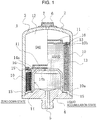
- FIG. 1 shows a cross section of an accumulator 1 with a metal bellows 10 according to a first embodiment of the present invention.
- the left side of the figure shows a contracted state of the metal bellows 10, and the right side of the figure shows an extended state of the metal bellows 10.
- the accumulator 1 shown in FIG. 1 is a metal bellows-type accumulator including the metal bellows 10 formed as a bellows, and is configured as below.
- an accumulator housing 2 with an oil port 4 connected to pressure piping (not shown) is provided.
- the metal bellows 10 and a bellows cap 11 are disposed in the interior of the housing 2 to partition the interior space of the housing 2 into a gas chamber 12 in which highpressure gas (e.g. nitrogen gas) is sealed, and a liquid chamber 13 communicating with a port hole 5 of the oil port 4.
- the housing 2 consists of a combination of a bottomed cylindrical shell 3 and the oil port 4 fixed (welded) to an opening of the shell 3.
- a gas inlet 6 for injecting gas into the gas chamber 12 is provided at a bottom portion of the shell 3, and is closed by a gas plug 7 after gas injection.
- the metal bellows 10 is fixed (welded) at a fixed end 10a thereof to an inner surface of the oil port 4, a port-side inner surface of the housing 2, via a fitting member 15 such as a collar, and is fixed (welded) at a freely moving end 10b thereof to the bellows cap 11 in a disk shape via a fitting member 15 such as a collar.
- a vibration damping ring 16 is fitted across an outer peripheral edge of the bellows cap 11 and the freely moving end 10b so as to prevent the radial vibration of the metal bellows 10 and guide the axial movement of the metal bellows 10 in the shell 3 during extension and contraction operations.
- the accumulator 1 is shown as an external gas-type accumulator in which the gas chamber 12 is disposed on the outer peripheral side of the metal bellows 10 and the liquid chamber 13 is disposed on the inner peripheral side of the metal bellows 10.
- An annular or a tubular stay 14 is positioned at and fixed (welded) to a port-side inner surface of the housing 2, that is, an inner surface of the oil port 4.
- the bellows cap 11 abuts so as to freely come into contact with or separate from an end (top end in the figure) of the stay 14.
- An inward flange 14a is provided at an inner peripheral surface of the stay 14. The inner periphery of the flange 14a defines a communicating hole 14b.
- FIG. 2 shows a free length state of the metal bellows 10 neither extended nor contracted in an early stage of incorporation.
- a dashed dotted line extending horizontally in a sheet lower portion shows the center of the metal bellows 10.
- the sheet left side is the side of the freely moving end 10b, and the right side is the side of the fixed end 10a.
- the metal bellows 10 is a metal bellows annular-shaped and having, axially repeatedly, a structure in which, from an axial end portion, a belly, a valley, a belly, a peak, and a belly are integrally formed in series in this order.
- An end portion 10c has a first connection belly 10d connected to the fitting member 15 such as a collar, and a connection valley 10e and a second connection belly 10f extending sequentially from the first connection belly 10d toward the fixed end 10a located at the other axial end.
- a peak 10g, a belly 10h, a valley 10i, a belly 10j, a peak 10k, a belly 101, a valley 10m, ... continue sequentially toward the fixed end 10a.
- the inner diameter di of valleys and the outer diameter do of peaks of the metal bellows 10 are each set the same.
- the peaks 10g, 10k, ... are each formed between adjacent valleys on both sides of the peaks in such a manner that, for example, the peak 10k is located in a position offset with respect to the center 17 of the pitch between the adjacent valleys 10i and 10m on both sides of the peak 10k in a direction opposite to the side of arc-shaped protrusions of the bellies 10j and 101 (The left direction in FIG. 2 .
- offset side it is sometimes referred to as an "offset side.”
- the metal bellows 10 of the present invention is characterized in that the axial width b1 of the connection valley 10e of the end portion 10c is set larger than the axial width b2 of the valleys 10i, 10m, ..., or the axial width b3 of the peaks 10g, 10k, ... in a portion other than the end portion 10c.
- the axial width b1 of the connection valley 10e is set in the range of one-and-a-half to five times the axial width b2 of the valleys 10i, 10m, ... or the axial width b3 of the peaks 10g, 10k, ....
- the axial width of valleys (including connection valleys) or peaks in the present invention means an axial width at a radial position connecting connections at each valley between the valley and bellies on both sides thereof, or connections at each peak between the peak and bellies on both sides thereof.
- the positions of connections between a valley or a peak and bellies on both sides thereof cannot be determined uniformly.
- an axial width at a position X outwardly distant from the lowest point of the connection valley 10e and the valleys 10i, 10m, ... by a certain distance ⁇ , or a position Y inwardly distant from the highest point of the peaks 10g, 10k, ... by a certain distance ⁇ may be used as their axial width.
- connection valley 10e of the end portion 10c has a linear portion s at which an axial central portion of the connection valley 10e is parallel to the axial direction. Opposite sides of the linear portion s are smoothly connected to the first connection belly 10d and the second connection belly 10f via respective arc-shaped r and r.
- connection valley 10e at the end portion 10c on the side of the freely moving end 10b of the metal bellows 10 a mounting portion 16a of the vibration damping ring 16 is inserted so that it abuts a surface of the connection valley 10e.
- the vibration damping ring 16 can be mounted securely. Even when the vibration damping ring 16 receives an external force from the side of the shell 3 while guiding the axial movement of the metal bellows 10 in the shell 3 during extension and contraction operations, disengagement or the like of the vibration damping ring 16 can be prevented.
- an end portion 10c on the side of the fixed end 10a is formed in the same manner as the end portion 10c on the side of the freely moving end 10b.
- the present invention is not limited to this, and may have only the end portion 10c on one side.
- the metal bellows 10 is not limited to an offset type as shown in FIG. 2 , and, needless to say, can be applied to a different type of metal bellows such as a U-shaped bellows with peaks and valleys shaped like a letter U as in Conventional Art 1, or a bellows with peaks of a U-shaped cross-sectional shape protruding outward of the tube, and valleys of a V-shaped cross-sectional shape protruding inward of the tube as in Conventional Art 2.
- a U-shaped bellows with peaks and valleys shaped like a letter U as in Conventional Art 1 or a bellows with peaks of a U-shaped cross-sectional shape protruding outward of the tube, and valleys of a V-shaped cross-sectional shape protruding inward of the tube as in Conventional Art 2.
- pressure Pin acts on the inner diameter side of the metal bellows 10
- pressure Pout acts on the outer diameter side thereof.
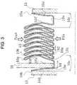
- the bellies 10f, 10h, 10j, 101, ... are axially pressed into an axially compressed state as shown in FIG. 3 .
- the amount of deformation of the end portions 10c is small since the axial width b1 of the connection valleys 10e is set larger than the axial width b2 of the valleys 10i, 10m, ... or the axial width b3 of the peaks 10g, 10k, ....
- connection valleys 10e, which have the linear portions s and the larger axial width b1 are thus resistant to axial extension and contraction deformation.
- the amount of deformation of the connection valleys 10e, and hence, the amount of deformation of the end portions 10c decrease.
- the mounting portion 16a of the vibration damping ring 16 When the mounting portion 16a of the vibration damping ring 16 is inserted into the connection valley 10e at the end portion 10c on the side of the freely moving end 10b of the metal bellows 10 so that it abuts the surface of the connection valley 10e, the mounting of the vibration damping ring 16 becomes secure. Even when the vibration damping ring 16 is brought into contact with the shell 3, receiving an external force while axially moving of the metal bellows 10 in the shell 3 during extension and contraction operations, disengagement or the like of the vibration damping ring 16 can be prevented.
- connection valley 10e which has the linear portion s and the larger axial width b1
- the connection valley 10e which has the linear portion s and the larger axial width b1
- the metal bellows 10 annular-shaped and having, axially repeatedly, a structure in which, from the axial end portion 10c, a belly, a valley, and a belly are integrally formed in series in this order, in which the end portion 10c has the first connection belly 10d connected to the fitting member 15, and the connection valley 10e and the second connection belly 10f extending sequentially from the first connection belly 10d axially inward, the axial central portion of the connection valley 10e has the linear portion s parallel to the axial direction, and the axial width b1 of the connection valley 10e in a free state is set larger than the axial width of the valleys 10i, 10m, ... or the peaks 10g, 10k, ... in a portion other than the end portion 10c, thus achieves the following effects.
- the metal bellows 10 according to the second embodiment is different from that in the first embodiment in the shape of a connection valley.
- Other basic configuration is identical to that in the first embodiment, and the same members are given the same reference numerals and letters, and redundant descriptions will be omitted.
- An end portion 10c has a first connection belly 10d connected to a fitting member 15 such as a collar, and a connection valley 10e-1 and a second connection belly 10f extending sequentially from the first connection belly 10d toward the side of a fixed end 10a located at the other axial end.
- a peak 10g, a belly 10h, a valley 10i, a belly 10j, a peak 10k, a belly 101, a valley 10m, ... continue sequentially toward the fixed end 10a.
- the inner diameter di of valleys and the outer diameter do of peaks of the metal bellows 10 are each set the same.
- the metal bellows 10 of the present invention is characterized in that the axial width b1 of the connection valley 10e-1 of the end portion 10c is set larger than the axial width b2 of the valleys 10i, 10m, ..., or the axial width b3 of the peaks 10g, 10k, ... in a portion other than the end portion 10c.
- the axial width b1 of the connection valley 10e-1 is set in the range of one-and-a-half to five times the axial width b2 of the valleys 10i, 10m, ... or the axial width b3 of the peaks 10g, 10k, ....
- connection valley 10e-1 of the end portion 10c is formed by an arc portion having a curvature radius R larger than that of the arc of the valleys 10i, 10m, ... or the peaks 10g, 10k, ... other than the end portion 10c.
- a mounting portion 16a of a vibration damping ring 16 is inserted into the connection valley 10e-1 at the end portion 10c on the side of the freely moving end 10b of the metal bellows 10 so that it abuts a surface of the connection valley 10e-1.
- the vibration damping ring 16 can be mounted securely. Even when the vibration damping ring 16 receives an external force from the side of the shell 3 while guiding the axial movement of the metal bellows 10 in a shell 3 during extension and contraction operations, disengagement or the like of the vibration damping ring 16 can be prevented.
- an end portion 10c on the side of the fixed end 10a is formed in the same manner as the end portion 10c on the side of the freely moving end 10b.
- the present invention is not limited to this, and may have only the end portion 10c on one side.
- pressure Pin acts on the inner diameter side of the metal bellows 10
- pressure Pout acts on the outer diameter side thereof.
- the bellies 10f, 10h, 10j, 101, ... are axially pressed into an axially compressed state.
- the amount of deformation of the end portions 10c is small since the axial width b1 of the connection valleys 10e-1 is set larger than the axial width b2 of the valleys 10i, 10m, ... or the axial width b3 of the peaks 10g, 10k, ....
- connection valleys 10e-1 which are formed by the arc portions with the larger curvature radius R and have the larger axial width b1, are thus resistant to axial extension and contraction deformation.
- the amount of deformation of the connection valleys 10e-1, and hence, the amount of deformation of the end portions 10c decrease.
- the mounting portion 16a of the vibration damping ring 16 When the mounting portion 16a of the vibration damping ring 16 is inserted into the connection valley 10e-1 at the end portion 10c on the side of the freely moving end 10b of the metal bellows 10 so that it abuts the surface of the connection valley 10e-1, the mounting of the vibration damping ring 16 becomes secure. Even when the vibration damping ring 16 is brought into contact with the shell 3, receiving an external force while axially moving of the metal bellows 10 in the shell 3 during extension and contraction operations, disengagement or the like of the vibration damping ring 16 can be prevented.
- connection valley 10e-1 which is formed by the arc portion with the larger curvature radius R and has the larger axial width b1
- the connection valley 10e-1 which is formed by the arc portion with the larger curvature radius R and has the larger axial width b1
- breakage of the first connection belly 10d and the second connection belly 10f can be prevented, and the life of the metal bellows 10 can be extended.
- the metal bellows 30 according to the third embodiment is different from that in the first embodiment in the shape of an end portion.
- Other basic configuration is identical to that in the first embodiment, and redundant descriptions will be omitted.
- An end portion 30c has a first connection belly 30d connected to a fitting member 15 such as a collar, and a connection peak 30e and a second connection belly 30f extending sequentially from the first connection belly 30d toward the side of a fixed end 30a located at the other axial end.
- a valley 30g, a belly 30h, a peak 30i, a belly 30j, a valley 30k, a belly 301, a peak 30m, ... continue sequentially toward the fixed end 30a.
- the inner diameter di of valleys and the outer diameter do of peaks of the metal bellows 30 are each set the same.
- the metal bellows 30 of the present invention is characterized in that the axial width b1 of the connection peak 30e of the end portion 30c is set larger than the axial width b2 of the valleys 30g, 30k, ... or the axial width b3 of the peaks 30i, 30m, ... in a portion other than the end portion 30c.
- the axial width b1 of the connection peak 30e is set in the range of one-and-a-half to five times the axial width b2 of the valleys 30g, 30k, ... or the axial width b3 of the peaks 30i, 30m, ....
- connection peak 30e of the end portion 30c has a linear portion s at which an axial central portion of the connection peak 30e is parallel to the axial direction. Opposite sides of the linear portion s are smoothly connected to the first connection belly 30d and the second connection belly 30f via respective arc-shaped r and r.
- pressure Pin acts on the inner diameter side of the metal bellows 30, and pressure Pout acts on the outer diameter side thereof.
- connection peaks 30e which have the linear portions s and the larger axial width b1, are thus resistant to axial extension and contraction deformation.
- the amount of deformation of the connection peaks 30e and hence, the amount of deformation of the end portions 30c decrease.
- the metal bellows 30 annular-shaped and having, axially repeatedly, a structure in which, from the axial end portion 30c, a belly, a peak, a belly, a valley, and a belly are integrally formed in series in this order, in which the end portion 30c has the first connection belly 30d connected to the fitting member 15, and the connection peak 30e and the second connection belly 30f extending sequentially from the first connection belly 30d axially inward, the axial central portion of the connection peak 30e has the linear portion s parallel to the axial direction, and the axial width of the connection peak 30e in a free state is set larger than the axial width of the peaks 30i, 30m, ... or the valleys 30g, 30k, ... in a portion other than the end portion 30c, thus achieves the following effects.
- the above embodiments have described the case where the metal bellows 10 and 30 according to the present invention are fitted in an accumulator, but are not limited to this, and can be used in other industrial fields including pipe lines.
- the above embodiments have described the case where the metal bellows 10 and 30 are offset type, but the present invention is not limited to this, and can be applied to a different type of metal bellows such as a U-shaped bellows with peaks and valleys shaped like a letter U as in Conventional Art 1, or a bellows with peaks of a U-shaped cross-sectional shape protruding outward of the tube, and valleys of a V-shaped cross-sectional shape protruding inward of the tube as in Conventional Art 2.
- a U-shaped bellows with peaks and valleys shaped like a letter U as in Conventional Art 1 or a bellows with peaks of a U-shaped cross-sectional shape protruding outward of the tube, and valleys of a V-shaped cross-sectional shape protruding inward of the tube as in Conventional Art 2.
Landscapes
- Engineering & Computer Science (AREA)
- General Engineering & Computer Science (AREA)
- Mechanical Engineering (AREA)
- Physics & Mathematics (AREA)
- Fluid Mechanics (AREA)
- Diaphragms And Bellows (AREA)
- Supply Devices, Intensifiers, Converters, And Telemotors (AREA)
Abstract
Description
- The present invention relates to a metal bellows. More particularly, a metal bellows of the present invention relates to a formed bellows suitably suitable for a component of an accumulator for vehicle use or the like.
- In conventional metal bellows, for example, formed metal bellows, U-shaped bellows with peaks and valleys shaped like a letter U are known (See
Patent Documents Conventional Art 1."). - Also known are metal bellows characterized in that an accordion-like tube wall has peaks of a U-shaped cross-sectional shape protruding outward of the tube, and valleys of a V-shaped cross-sectional shape protruding inward of the tube (See
Patent Document 3, for example. Hereinafter, they are referred to as "Conventional Art 2."). -
- Patent Document 1:
JP 2539905 B1 - Patent Document 2:
JP 2005-48902 A - Patent Document 3:
JP 2009-8184 A - However,
Conventional Art 1 andConventional Art 2 described above have a problem that a pitch representing a dimension from a peak to a peak or from a valley to a valley of a metal bellows is constant over the entire length, and thus when both end portions thereof are fixed to collar members by welding or the like for use in a device such as an accumulator, great stress acts particularly on the both end portions connected to the collar members, breaking the both end portions. - When a metal bellows is used in a device such as an accumulator, a vibration damping ring is fitted to one free-side end portion thereof. When the pitch is constant over the entire length as in
Conventional Art 1 andConventional Art 2, the width of a valley portion in which the vibration damping ring is pinched is also constant in conjunction with the pitch. Thus, there is a problem that the axial width of the vibration dampening ring is limited within the width of the valley portion, or when a gap between the vibration dampening ring and bellies on both sides of the valley portion is small, the vibration dampening ring abuts the bellies, breaking the bellies. - It is a first object of the present invention to provide a metal bellows of great durability capable of preventing breakage at both end portions of the metal bellows.
- It is a second object of the present invention to provide a metal bellows capable of providing spaces for members including a vibration damping ring when they are fitted to the both end portions of the metal bellows, and preventing breakage of the both end portions.
- To attain the above object, a metal bellows according to a first aspect of the present invention is a metal bellows in an annular shape, including, axially repeatedly, a structure in which, from an axial end portion, a belly, a valley, a belly, a peak, and a belly are integrally formed in series sequentially in this order, in which the end portion has a first connection belly connected to a fitting member, and a connection valley and a second connection belly extending sequentially from the first connection belly axially inward, and the connection valley in a free state has an axial width set larger than an axial width of valleys or peaks in a portion other than the end portion.
- According to this aspect, the amount of deformation of the connection valley at the end portion of the metal bellows, and hence, the amount of deformation of the end portion can be reduced, bending stress occurring at the end portion can be reduced, and stress-caused breakage of the end portion where stress is relatively concentrated can be prevented. Thus the life of the metal bellows can be extended.
- Further, a lateral space for fitting a vibration damping ring to the connection valley at the end portion of the metal bellows can be provided, which allows secure mounting of the vibration damping ring, and prevents the first connection belly and the second connection belly from striking a mounting portion of the vibration damping ring even when the metal bellows contracts. Thus breakage of the first connection belly and the second connection belly can be prevented, and the life of the metal bellows can be extended.
- A metal bellows according to a second aspect of the present invention is a metal bellows in an annular shape, including, axially repeatedly, a structure in which, from an axial end portion, a belly, a peak, a belly, a valley, and a belly are integrally formed in series in this order, in which the end portion has a first connection belly connected to a fitting member, and a connection peak and a second connection belly extending sequentially from the first connection belly axially inward, and the connection peak in a free state has an axial width set larger than an axial width of peaks or valleys in a portion other than the end portion.
- According to this aspect, the amount of deformation of the connection valley at the end portion of the metal bellows, and hence, the amount of deformation of the end portion can be reduced, bending stress occurring at the end portion can be reduced, and stress-caused breakage of the end portion where stress is relatively concentrated can be prevented. Thus the life of the metal bellows can be extended.
- According to a third aspect of the present invention, in the metal bellows in the first or second aspect, the connection valley or the connection peak includes a linear portion parallel to an axial direction.
- According to this aspect, the axial width of the connection valley or the connection peak in the free state can be easily increased.
- According to a fourth aspect of the present invention, in the metal bellows in the first or second aspect, the connection valley or the connection peak is formed by an arc portion with a curvature radius larger than a curvature radius of valleys or peaks in a portion other than the end portion.
- According to this aspect, the connection valley or the connection peak can be entirely formed by a smooth curve when the axial width of the connection valley or the connection peak in the free state is increased, and stress concentration at the connection valley or the connection peak can be prevented.
- According to a fifth aspect of the present invention, in the metal bellows in the first aspect, a vibration damping ring for guiding axial movement of the metal bellows in a shell during extension and contraction operations is provided in the connection valley at an end portion on a freely moving end side of the metal bellows.
- According to this aspect, the vibration damping ring is mounted securely, so that the vibration damping ring can sufficiently exert a guiding function.
- The present invention achieves the following outstanding effects.
- (1) The axial end portion of the metal bellows has the first connection belly connected to the fitting member, and the connection valley and the second connection belly extending sequentially from the first connection belly axially inward, and the connection valley in the free state has the axial width set larger than the axial width of the valleys or the peaks in the portion other than the end portion, so that the amount of deformation of the connection valley at the end portion of the metal bellows, and hence, the amount of deformation of the end portion can be reduced, bending stress occurring at the end portion can be reduced, and stress-caused breakage of the end portion where stress is relatively concentrated can be prevented. Thus the life of the metal bellows can be extended.
Further, the lateral space for fitting the vibration damping ring to the connection valley at the end portion of the metal bellows can be provided, which allows secure mounting of the vibration damping ring, and prevents the first connection belly and the second connection belly from striking the mounting portion of the vibration damping ring even when the metal bellows contracts. Thus breakage of the first connection belly and the second connection belly can be prevented, and the life of the metal bellows can be extended. - (2) The axial end portion of the metal bellows has the first connection belly connected to the fitting member, and the connection peak and the second connection belly extending sequentially from the first connection belly axially inward, and the connection peak in the free state has the axial width set larger than the axial width of the peaks or the valleys in the portion other than the end portion, so that the amount of deformation of the connection valley at the end portion of the metal bellows, and hence, the amount of deformation of the end portion can be reduced, bending stress occurring at the end portion can be reduced, and stress-caused breakage of the end portion where stress is relatively concentrated can be prevented. Thus the life of the metal bellows can be extended.
- (3) The connection valley or the connection peak includes the linear portion parallel to the axial direction, so that the axial width of the connection peak in the free state can be easily increased.
- (4) The connection valley or the connection peak is formed by the arc portion with the curvature radius larger than the curvature radius of the valleys or the peaks in the portion other than the end portion, so that the connection valley or the connection peak can be entirely formed by a smooth curve when the axial width of the connection valley or the connection peak in the free state is increased, and stress concentration at the connection valley or the connection peak can be prevented.
- (5) The vibration damping ring for guiding axial movement of the metal bellows in the shell during extension and contraction operations is provided in the connection valley at the end portion on the freely moving end side of the metal bellows, so that the vibration damping ring is mounted securely. Thus the vibration damping ring can sufficiently exert a guiding function.
-
-
FIG. 1 is a vertical cross-sectional view of an accumulator with a metal bellows according to a first embodiment of the present invention. -
FIG. 2 is an axially half-cut cross-sectional view of a major part showing a free length state of the metal bellows neither extended nor contracted in an early stage of incorporation according to the first embodiment of the present invention. -
FIG. 3 is an axially half-cut cross-sectional view of the major part showing a contact length state of the metal bellows according to the first embodiment of the present invention. -
FIG. 4 is an axially half-cut cross-sectional view of a major part showing a free length state of a metal bellows neither extended nor contracted in an early stage of incorporation according to a second embodiment of the present invention. -
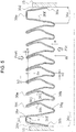
FIG. 5 is an axially half-cut cross-sectional view of a major part showing a free length state of a metal bellows neither extended nor contracted in an early stage of incorporation according to a third embodiment of the present invention. - Hereinafter with reference to the drawings, forms for implementing this invention will be described illustratively based on embodiments. However, the dimensions, materials, shapes, relative arrangements, and others of components described in the embodiments are not intended to limit the scope of the present invention only to them unless otherwise explicitly described.
-
FIG. 1 shows a cross section of anaccumulator 1 with ametal bellows 10 according to a first embodiment of the present invention. The left side of the figure shows a contracted state of themetal bellows 10, and the right side of the figure shows an extended state of themetal bellows 10. - The
accumulator 1 shown inFIG. 1 is a metal bellows-type accumulator including themetal bellows 10 formed as a bellows, and is configured as below. - First, an
accumulator housing 2 with anoil port 4 connected to pressure piping (not shown) is provided. Themetal bellows 10 and abellows cap 11 are disposed in the interior of thehousing 2 to partition the interior space of thehousing 2 into agas chamber 12 in which highpressure gas (e.g. nitrogen gas) is sealed, and aliquid chamber 13 communicating with aport hole 5 of theoil port 4. Thehousing 2 consists of a combination of a bottomedcylindrical shell 3 and theoil port 4 fixed (welded) to an opening of theshell 3. Agas inlet 6 for injecting gas into thegas chamber 12 is provided at a bottom portion of theshell 3, and is closed by agas plug 7 after gas injection. - The
metal bellows 10 is fixed (welded) at a fixedend 10a thereof to an inner surface of theoil port 4, a port-side inner surface of thehousing 2, via afitting member 15 such as a collar, and is fixed (welded) at a freely movingend 10b thereof to thebellows cap 11 in a disk shape via afitting member 15 such as a collar. - A
vibration damping ring 16 is fitted across an outer peripheral edge of thebellows cap 11 and the freely movingend 10b so as to prevent the radial vibration of themetal bellows 10 and guide the axial movement of themetal bellows 10 in theshell 3 during extension and contraction operations. - In
FIG. 1 , theaccumulator 1 is shown as an external gas-type accumulator in which thegas chamber 12 is disposed on the outer peripheral side of the metal bellows 10 and theliquid chamber 13 is disposed on the inner peripheral side of the metal bellows 10. - An annular or a
tubular stay 14 is positioned at and fixed (welded) to a port-side inner surface of thehousing 2, that is, an inner surface of theoil port 4. The bellows cap 11 abuts so as to freely come into contact with or separate from an end (top end in the figure) of thestay 14. Aninward flange 14a is provided at an inner peripheral surface of thestay 14. The inner periphery of theflange 14a defines a communicatinghole 14b. - Next, the metal bellows 10 will be described.
-
FIG. 2 shows a free length state of the metal bellows 10 neither extended nor contracted in an early stage of incorporation. A dashed dotted line extending horizontally in a sheet lower portion shows the center of the metal bellows 10. The sheet left side is the side of the freely movingend 10b, and the right side is the side of thefixed end 10a. - In
FIG. 2 , the metal bellows 10 is a metal bellows annular-shaped and having, axially repeatedly, a structure in which, from an axial end portion, a belly, a valley, a belly, a peak, and a belly are integrally formed in series in this order. - Now, the side of the freely moving
end 10b of the metal bellows 10 will be described. Anend portion 10c has afirst connection belly 10d connected to thefitting member 15 such as a collar, and aconnection valley 10e and asecond connection belly 10f extending sequentially from thefirst connection belly 10d toward thefixed end 10a located at the other axial end. - Subsequent to the
second connection belly 10f, apeak 10g, abelly 10h, a valley 10i, abelly 10j, apeak 10k, abelly 101, avalley 10m, ... continue sequentially toward thefixed end 10a. - In
FIG. 2 , the inner diameter di of valleys and the outer diameter do of peaks of the metal bellows 10 are each set the same. - In the free length state of the metal bellows 10 neither extended nor contacted in an early stage of incorporation, the
valleys 10i, 10m, ... each turn around in a U shape in cross section, and thepeaks - Further, the
peaks peak 10k is located in a position offset with respect to thecenter 17 of the pitch between theadjacent valleys 10i and 10m on both sides of the peak 10k in a direction opposite to the side of arc-shaped protrusions of thebellies 10j and 101 (The left direction inFIG. 2 . Hereinafter it is sometimes referred to as an "offset side."). - The metal bellows 10 of the present invention is characterized in that the axial width b1 of the
connection valley 10e of theend portion 10c is set larger than the axial width b2 of thevalleys 10i, 10m, ..., or the axial width b3 of thepeaks end portion 10c. - For example, the axial width b1 of the
connection valley 10e is set in the range of one-and-a-half to five times the axial width b2 of thevalleys 10i, 10m, ... or the axial width b3 of thepeaks - The axial width of valleys (including connection valleys) or peaks in the present invention means an axial width at a radial position connecting connections at each valley between the valley and bellies on both sides thereof, or connections at each peak between the peak and bellies on both sides thereof. However, in some cases, the positions of connections between a valley or a peak and bellies on both sides thereof cannot be determined uniformly. Thus, for the sake of convenience, an axial width at a position X outwardly distant from the lowest point of the
connection valley 10e and thevalleys 10i, 10m, ... by a certain distance α, or a position Y inwardly distant from the highest point of thepeaks - The
connection valley 10e of theend portion 10c has a linear portion s at which an axial central portion of theconnection valley 10e is parallel to the axial direction. Opposite sides of the linear portion s are smoothly connected to thefirst connection belly 10d and thesecond connection belly 10f via respective arc-shaped r and r. - The proportion of the linear portion s to the axial width b1 of the
connection valley 10e is determined in design, and is preferably in the range of s/b1 = 0.1 to 0.9, for example, and more preferably, in the range of s/b1 = 0.65 to 0.68. - Into the
connection valley 10e at theend portion 10c on the side of the freely movingend 10b of the metal bellows 10, a mountingportion 16a of thevibration damping ring 16 is inserted so that it abuts a surface of theconnection valley 10e. When the mountingportion 16a of thevibration damping ring 16 is inserted to abut the surface of theconnection valley 10e in this manner, thevibration damping ring 16 can be mounted securely. Even when thevibration damping ring 16 receives an external force from the side of theshell 3 while guiding the axial movement of the metal bellows 10 in theshell 3 during extension and contraction operations, disengagement or the like of thevibration damping ring 16 can be prevented. - In
FIG. 2 , anend portion 10c on the side of thefixed end 10a is formed in the same manner as theend portion 10c on the side of the freely movingend 10b. The present invention is not limited to this, and may have only theend portion 10c on one side. - In the present invention, the metal bellows 10 is not limited to an offset type as shown in
FIG. 2 , and, needless to say, can be applied to a different type of metal bellows such as a U-shaped bellows with peaks and valleys shaped like a letter U as inConventional Art 1, or a bellows with peaks of a U-shaped cross-sectional shape protruding outward of the tube, and valleys of a V-shaped cross-sectional shape protruding inward of the tube as inConventional Art 2. - Now, assume that pressure Pin acts on the inner diameter side of the metal bellows 10, and pressure Pout acts on the outer diameter side thereof.
- When Pout > Pin, the
bellies FIG. 3 . At this time, at theend portion 10c on the side of thefixed end 10a and theend portion 10c on the side of the freely movingend 10b, the amount of deformation of theend portions 10c is small since the axial width b1 of theconnection valleys 10e is set larger than the axial width b2 of thevalleys 10i, 10m, ... or the axial width b3 of thepeaks valleys 10i, 10m, ..., which are U-shaped in cross section and have the smaller axial width b2, and thepeaks connection valleys 10e, which have the linear portions s and the larger axial width b1, are thus resistant to axial extension and contraction deformation. The amount of deformation of theconnection valleys 10e, and hence, the amount of deformation of theend portions 10c decrease. - When the amount of deformation of the
end portions 10c decreases, bending stress occurring at theend portions 10c decreases. Stress-caused breakage of theend portions 10c where stress is relatively concentrated can be prevented, and the life of the metal bellows 10 can be extended. - When the mounting
portion 16a of thevibration damping ring 16 is inserted into theconnection valley 10e at theend portion 10c on the side of the freely movingend 10b of the metal bellows 10 so that it abuts the surface of theconnection valley 10e, the mounting of thevibration damping ring 16 becomes secure. Even when thevibration damping ring 16 is brought into contact with theshell 3, receiving an external force while axially moving of the metal bellows 10 in theshell 3 during extension and contraction operations, disengagement or the like of thevibration damping ring 16 can be prevented. - Further, even when the metal bellows 10 contracts as shown in
FIG. 3 , theconnection valley 10e, which has the linear portion s and the larger axial width b1, thus prevents thefirst connection belly 10d and thesecond connection belly 10f from striking the mountingportion 16a of thevibration damping ring 16. Thus breakage of thefirst connection belly 10d and thesecond connection belly 10f can be prevented, and the life of the metal bellows 10 can be extended. - In the above-described first embodiment, the metal bellows 10 annular-shaped and having, axially repeatedly, a structure in which, from the
axial end portion 10c, a belly, a valley, and a belly are integrally formed in series in this order, in which theend portion 10c has thefirst connection belly 10d connected to thefitting member 15, and theconnection valley 10e and thesecond connection belly 10f extending sequentially from thefirst connection belly 10d axially inward, the axial central portion of theconnection valley 10e has the linear portion s parallel to the axial direction, and the axial width b1 of theconnection valley 10e in a free state is set larger than the axial width of thevalleys 10i, 10m, ... or thepeaks end portion 10c, thus achieves the following effects. - (1) The amount of deformation of the
connection valley 10e at theend portion 10c of the metal bellows 10, and hence, the amount of deformation of theend portion 10c can be reduced. Bending stress occurring at theend portion 10c can be reduced. Stress-caused breakage of theend portion 10c where stress is relatively concentrated can be prevented. Thus the life of the metal bellows 10 can be extended. - (2) A lateral space for fitting the
vibration damping ring 16 to theconnection valley 10e at theend portion 10c of the metal bellows 10 can be provided, which allows secure mounting of thevibration damping ring 16, and prevents thefirst connection belly 10d and thesecond connection belly 10f from striking the mountingportion 16a of thevibration damping ring 16 even when the metal bellows 10 contracts. Thus breakage of thefirst connection belly 10d and thesecond connection belly 10f can be prevented, and the life of the metal bellows 10 can be extended. - (3) Further, the
connection valley 10e includes the linear portion s parallel to the axial direction, so that the axial width of theconnection valley 10e in the free state can be easily increased. - (4) Further, the
vibration damping ring 16 for guiding the axial movement of the metal bellows 10 in theshell 3 during extension and contraction operations is provided in theconnection valley 10e at theend portion 10c on the side of the freely movingend 10b of the metal bellows 10, so that thevibration damping ring 16 can be mounted securely. Thus thevibration damping ring 16 can sufficiently exert a guiding function. - With reference to
FIG. 4 , a metal bellows 10 according to a second embodiment of the present invention will be described. - The metal bellows 10 according to the second embodiment is different from that in the first embodiment in the shape of a connection valley. Other basic configuration is identical to that in the first embodiment, and the same members are given the same reference numerals and letters, and redundant descriptions will be omitted.
- In
FIG. 4 , the side of a freely movingend 10b of the metal bellows 10 will be described. Anend portion 10c has afirst connection belly 10d connected to afitting member 15 such as a collar, and aconnection valley 10e-1 and asecond connection belly 10f extending sequentially from thefirst connection belly 10d toward the side of afixed end 10a located at the other axial end. - As in the first embodiment, subsequent to the
second connection belly 10f, apeak 10g, abelly 10h, a valley 10i, abelly 10j, apeak 10k, abelly 101, avalley 10m, ... continue sequentially toward thefixed end 10a. - In
FIG. 4 , as in the first embodiment, the inner diameter di of valleys and the outer diameter do of peaks of the metal bellows 10 are each set the same. - The metal bellows 10 of the present invention is characterized in that the axial width b1 of the
connection valley 10e-1 of theend portion 10c is set larger than the axial width b2 of thevalleys 10i, 10m, ..., or the axial width b3 of thepeaks end portion 10c. - For example, the axial width b1 of the
connection valley 10e-1 is set in the range of one-and-a-half to five times the axial width b2 of thevalleys 10i, 10m, ... or the axial width b3 of thepeaks - The
connection valley 10e-1 of theend portion 10c is formed by an arc portion having a curvature radius R larger than that of the arc of thevalleys 10i, 10m, ... or thepeaks end portion 10c. - A mounting
portion 16a of avibration damping ring 16 is inserted into theconnection valley 10e-1 at theend portion 10c on the side of the freely movingend 10b of the metal bellows 10 so that it abuts a surface of theconnection valley 10e-1. When the mountingportion 16a of thevibration damping ring 16 is inserted to abut the surface of theconnection valley 10e-1 in this manner, thevibration damping ring 16 can be mounted securely. Even when thevibration damping ring 16 receives an external force from the side of theshell 3 while guiding the axial movement of the metal bellows 10 in ashell 3 during extension and contraction operations, disengagement or the like of thevibration damping ring 16 can be prevented. - In
FIG. 4 , anend portion 10c on the side of thefixed end 10a is formed in the same manner as theend portion 10c on the side of the freely movingend 10b. The present invention is not limited to this, and may have only theend portion 10c on one side. - Now, assume that pressure Pin acts on the inner diameter side of the metal bellows 10, and pressure Pout acts on the outer diameter side thereof.
- When Pout > Pin, the
bellies end portion 10c on the side of thefixed end 10a and theend portion 10c on the side of the freely movingend 10b, the amount of deformation of theend portions 10c is small since the axial width b1 of theconnection valleys 10e-1 is set larger than the axial width b2 of thevalleys 10i, 10m, ... or the axial width b3 of thepeaks valleys 10i, 10m, ..., which are U-shaped in cross section and have the smaller axial width b, and thepeaks connection valleys 10e-1, which are formed by the arc portions with the larger curvature radius R and have the larger axial width b1, are thus resistant to axial extension and contraction deformation. The amount of deformation of theconnection valleys 10e-1, and hence, the amount of deformation of theend portions 10c decrease. - When the amount of deformation of the
end portions 10c decreases, bending stress occurring at theend portions 10c decreases. Stress-caused breakage of theend portions 10c where stress is relatively concentrated can be prevented, and the life of the metal bellows 10 can be extended. - When the mounting
portion 16a of thevibration damping ring 16 is inserted into theconnection valley 10e-1 at theend portion 10c on the side of the freely movingend 10b of the metal bellows 10 so that it abuts the surface of theconnection valley 10e-1, the mounting of thevibration damping ring 16 becomes secure. Even when thevibration damping ring 16 is brought into contact with theshell 3, receiving an external force while axially moving of the metal bellows 10 in theshell 3 during extension and contraction operations, disengagement or the like of thevibration damping ring 16 can be prevented. - Further, even when the metal bellows 10 contracts, the
connection valley 10e-1, which is formed by the arc portion with the larger curvature radius R and has the larger axial width b1, thus prevents thefirst connection belly 10d and thesecond connection belly 10f from striking the mountingportion 16a of thevibration damping ring 16. Thus breakage of thefirst connection belly 10d and thesecond connection belly 10f can be prevented, and the life of the metal bellows 10 can be extended. - In the above-described second embodiment, the metal bellows 10 annular-shaped and having, axially repeatedly, a structure in which, from the
axial end portion 10c, a belly, a valley, a belly, a peak, and a belly are integrally formed in series in this order, in which theend portion 10c has thefirst connection belly 10d connected to thefitting member 15, and theconnection valley 10e-1 and thesecond connection belly 10f extending sequentially from thefirst connection belly 10d axially inward, theconnection valley 10e-1 is formed by the arc portion with the larger curvature radius R, and the axial width b1 of theconnection valley 10e-1 in a free state is set larger than the axial width of thevalleys 10i, 10m, ... or thepeaks end portion 10c, thus achieves the following effects. - (1) The amount of deformation of the
connection valley 10e-1 at theend portion 10c of the metal bellows 10, and hence, the amount of deformation of theend portion 10c can be reduced. Bending stress occurring at theend portion 10c can be reduced. Stress-caused breakage of theend portion 10c where stress is relatively concentrated can be prevented. Thus the life of the metal bellows 10 can be extended. - (2) A lateral space for fitting the
vibration damping ring 16 to theconnection valley 10e-1 at theend portion 10c of the metal bellows 10 can be provided, which allows secure mounting of thevibration damping ring 16, and prevents thefirst connection belly 10d and thesecond connection belly 10f from striking the mountingportion 16a of thevibration damping ring 16 even when the metal bellows 10 contracts. Thus breakage of thefirst connection belly 10d and thesecond connection belly 10f can be prevented, and the life of the metal bellows 10 can be extended. - (3) Further, the
connection valley 10e-1 is formed by the arc portion with the curvature radius larger than the curvature radius of thevalleys 10i, 10m, ... or thepeaks end portion 10c, so that theconnection valley 10e-1 can be entirely formed by a smooth curve when the axial width of theconnection valley 10e-1 in the free state is increased, and stress concentration at theconnection valley 10e-1 can be prevented. - (4) Further, the
vibration damping ring 16 for guiding the axial movement of the metal bellows 10 in theshell 3 during extension and contraction operations is provided in theconnection valley 10e-1 at theend portion 10c on the side of the freely movingend 10b of the metal bellows 10, so that thevibration damping ring 16 can be mounted securely. Thus thevibration damping ring 16 can sufficiently exert a guiding function. - With reference to
FIG. 5 , a metal bellows 30 according to a third embodiment of the present invention will be described. - The metal bellows 30 according to the third embodiment is different from that in the first embodiment in the shape of an end portion. Other basic configuration is identical to that in the first embodiment, and redundant descriptions will be omitted.
- In
FIG. 5 , the side of a freely movingend 30b of the metal bellows 30 will be described. Anend portion 30c has afirst connection belly 30d connected to afitting member 15 such as a collar, and aconnection peak 30e and asecond connection belly 30f extending sequentially from thefirst connection belly 30d toward the side of afixed end 30a located at the other axial end. - As in the first embodiment, subsequent to the
second connection belly 30f, avalley 30g, abelly 30h, a peak 30i, abelly 30j, avalley 30k, abelly 301, apeak 30m, ... continue sequentially toward thefixed end 30a. - In
FIG. 5 , as in the first embodiment, the inner diameter di of valleys and the outer diameter do of peaks of the metal bellows 30 are each set the same. - The metal bellows 30 of the present invention is characterized in that the axial width b1 of the
connection peak 30e of theend portion 30c is set larger than the axial width b2 of thevalleys peaks 30i, 30m, ... in a portion other than theend portion 30c. - For example, the axial width b1 of the
connection peak 30e is set in the range of one-and-a-half to five times the axial width b2 of thevalleys peaks 30i, 30m, .... - The
connection peak 30e of theend portion 30c has a linear portion s at which an axial central portion of theconnection peak 30e is parallel to the axial direction. Opposite sides of the linear portion s are smoothly connected to thefirst connection belly 30d and thesecond connection belly 30f via respective arc-shaped r and r. - The proportion of the linear portion s to the axial width b1 of the
connection peak 30e is determined in design, and is preferably in the range of s/b1 = 0.1 to 0.9, for example, and more preferably, in the range of s/b1 = 0.65 to 0.68. - Now, assume that pressure Pin acts on the inner diameter side of the metal bellows 30, and pressure Pout acts on the outer diameter side thereof.
- When Pout > Pin, the
bellies end portion 30c on thefixed end 30a side and theend portion 30c on the freely movingend 30b side, the amount of deformation of theend portions 30c is small since the axial width b1 of theconnection peaks 30e is set larger than the axial width b2 of thevalleys peaks 30i, 30m, .... Specifically, while thevalleys peaks 30i, 30m, ..., which are arc-shaped in cross section and have the smaller axial width b3, are thus prone to axial extension and contraction deformation, theconnection peaks 30e, which have the linear portions s and the larger axial width b1, are thus resistant to axial extension and contraction deformation. The amount of deformation of theconnection peaks 30e , and hence, the amount of deformation of theend portions 30c decrease. - When the amount of deformation of the
end portions 30c decreases, bending stress occurring at theend portions 30c decreases. Stress-caused breakage of theend portions 30c where stress is relatively concentrated can be prevented, and the life of the metal bellows 30 can be extended. - In the above-described third embodiment, the metal bellows 30 annular-shaped and having, axially repeatedly, a structure in which, from the
axial end portion 30c, a belly, a peak, a belly, a valley, and a belly are integrally formed in series in this order, in which theend portion 30c has thefirst connection belly 30d connected to thefitting member 15, and theconnection peak 30e and thesecond connection belly 30f extending sequentially from thefirst connection belly 30d axially inward, the axial central portion of theconnection peak 30e has the linear portion s parallel to the axial direction, and the axial width of theconnection peak 30e in a free state is set larger than the axial width of thepeaks 30i, 30m, ... or thevalleys end portion 30c, thus achieves the following effects. - (1) The amount of deformation of the
connection peak 30e at theend portion 30c of the metal bellows 30, and hence, the amount of deformation of theend portion 30c can be reduced. Bending stress occurring at theend portion 30c can be reduced. Stress-caused breakage of theend portion 30c where stress is relatively concentrated can be prevented. Thus the life of the metal bellows 30 can be extended. - (2) Further, the
connection peaks 30e includes the linear portion s parallel to the axial direction, so that the axial width of the connection peaks 30e in the free state can be easily increased. - Although the embodiments of the present invention have been described above with reference to the drawings, specific configuration is not limited to the embodiments. Any changes and additions made without departing from the scope of the present invention are included in the present invention.
- For example, the above embodiments have described the case where the metal bellows 10 and 30 according to the present invention are fitted in an accumulator, but are not limited to this, and can be used in other industrial fields including pipe lines.
- Further, for example, the above embodiments have described the case where the metal bellows 10 and 30 are offset type, but the present invention is not limited to this, and can be applied to a different type of metal bellows such as a U-shaped bellows with peaks and valleys shaped like a letter U as in
Conventional Art 1, or a bellows with peaks of a U-shaped cross-sectional shape protruding outward of the tube, and valleys of a V-shaped cross-sectional shape protruding inward of the tube as inConventional Art 2. -
- 1 accumulator
- 2 housing
- 3 shell
- 4 oil port
- 5 port hole
- 6 gas inlet
- 7 gas plug
- 10, 30 metal bellows
- 10a, 30a fixed end
- 10b, 30b freely moving end
- 10c, 30c end portion
- 10d, 30d first connection belly
- 10f, 30f second connection belly
- 10e, 10e-1 connection valley
- 30e connection peak
- 10g, 10k, 30i, 30m peak
- 10i, 10m, 30g, 30k valley
- 10h, 10i, 101, 30h, 30j, 301 belly
- 11 bellows cap
- 12 gas chamber
- 13 liquid chamber
- 14 stay
- 15 fitting member (collar)
- 16 vibration damping ring
- 17 center of pitch of valleys
- di inner diameter of valley
- do outer diameter of peak
- X position distant outward from lowest point of valley by certain distance α
- Y position distant inward from highest point of peak by certain distance α
- s connection valley linear portion
- Pin pressure on inner diameter side
- Pout pressure on outer diameter side
Claims (5)
- A metal bellows in an annular shape, comprising, axially repeatedly, a structure in which, from an axial end portion, a belly, a valley, a belly, a peak, and a belly are integrally formed in series sequentially in this order, wherein
the end portion has a first connection belly connected to a fitting member, and a connection valley and a second connection belly extending sequentially from the first connection belly axially inward, and the connection valley in a free state has an axial width set larger than an axial width of valleys or peaks in a portion other than the end portion. - A metal bellows in an annular shape, comprising, axially repeatedly, a structure in which, from an axial end portion, a belly, a peak, a belly, a valley, and a belly are integrally formed in series in this order, wherein
the end portion has a first connection belly connected to a fitting member, and a connection peak and a second connection belly extending sequentially from the first connection belly axially inward, and the connection peak in a free state has an axial width set larger than an axial width of peaks or valleys in a portion other than the end portion. - The metal bellows according to claim 1 or 2, wherein the connection valley or the connection peak includes a linear portion parallel to an axial direction.
- The metal bellows according to claim 1 or 2, wherein the connection valley or the connection peak is formed by an arc portion with a curvature radius larger than a curvature radius of valleys or peaks in a portion other than the end portion.
- The metal bellows according to claim 1, wherein a vibration damping ring for guiding axial movement of the metal bellows in a shell during extension and contraction operations is provided in the connection valley at an end portion on a freely moving end side of the metal bellows.
Applications Claiming Priority (2)
| Application Number | Priority Date | Filing Date | Title |
|---|---|---|---|
| JP2015186171 | 2015-09-23 | ||
| PCT/JP2016/077047 WO2017051753A1 (en) | 2015-09-23 | 2016-09-14 | Metal bellows |
Publications (3)
| Publication Number | Publication Date |
|---|---|
| EP3354944A1 true EP3354944A1 (en) | 2018-08-01 |
| EP3354944A4 EP3354944A4 (en) | 2019-05-22 |
| EP3354944B1 EP3354944B1 (en) | 2023-05-10 |
Family
ID=58386700
Family Applications (1)
| Application Number | Title | Priority Date | Filing Date |
|---|---|---|---|
| EP16848541.5A Active EP3354944B1 (en) | 2015-09-23 | 2016-09-14 | Metal bellows |
Country Status (5)
| Country | Link |
|---|---|
| US (1) | US10520084B2 (en) |
| EP (1) | EP3354944B1 (en) |
| JP (1) | JP6800157B2 (en) |
| CN (1) | CN108138957B (en) |
| WO (1) | WO2017051753A1 (en) |
Families Citing this family (4)
| Publication number | Priority date | Publication date | Assignee | Title |
|---|---|---|---|---|
| CN107184364B (en) * | 2017-07-07 | 2018-04-17 | 北京恒通信佳科技发展有限公司 | A kind of bellows |
| DE102021002971A1 (en) * | 2021-06-10 | 2022-12-15 | Hydac Technology Gmbh | Separating element and hydraulic accumulator with such a separating element |
| DE102022207603B4 (en) * | 2022-07-25 | 2024-09-26 | Continental Automotive Technologies GmbH | Bellows |
| CN117759794B (en) * | 2024-02-22 | 2024-05-24 | 沈阳欧施盾新材料科技有限公司 | Seamless S-shaped swing hose and rocket engine |
Family Cites Families (25)
| Publication number | Priority date | Publication date | Assignee | Title |
|---|---|---|---|---|
| US1731130A (en) * | 1921-10-17 | 1929-10-08 | Fulton Sylphon Co | Flexible corrugated tubular wall and method for making the same |
| US2942838A (en) * | 1955-03-18 | 1960-06-28 | Melville F Peters | Vibration damping in fluid seals |
| US3469502A (en) * | 1967-02-09 | 1969-09-30 | Robert I Gardner | Bellows |
| JPS5776240U (en) * | 1980-10-30 | 1982-05-11 | ||
| JP2539905B2 (en) | 1989-01-20 | 1996-10-02 | 日本発条株式会社 | Accumulator |
| GB8909289D0 (en) * | 1989-04-24 | 1989-06-07 | Crane John Uk Ltd | Mechanical face seals |
| JPH0391571U (en) * | 1990-01-09 | 1991-09-18 | ||
| FR2671844B1 (en) * | 1991-01-17 | 1994-12-30 | Eg G | CURVED WAVE BELLOWS. |
| EP1052412B1 (en) * | 1999-05-12 | 2005-03-09 | NHK Spring Co., Ltd. | Accumulator and manufacturing process thereof |
| JP2003148616A (en) * | 2001-11-14 | 2003-05-21 | Saginomiya Seisakusho Inc | Welded metal bellows |
| JP2005048902A (en) | 2003-07-30 | 2005-02-24 | Nippon Valqua Ind Ltd | Production method of molded bellows and molded bellows obtained by the method |
| JP4311639B2 (en) * | 2003-11-07 | 2009-08-12 | 日本発條株式会社 | Method for producing metal bellows |
| JP2005155835A (en) * | 2003-11-27 | 2005-06-16 | Saginomiya Seisakusho Inc | Metal bellows, metal bellows / metal member joined product, and manufacturing method thereof |
| JP4735811B2 (en) * | 2005-04-15 | 2011-07-27 | Nok株式会社 | accumulator |
| JP2009008184A (en) * | 2007-06-28 | 2009-01-15 | Osaka Rasenkan Kogyo Kk | Metallic bellows |
| JP5535743B2 (en) * | 2009-05-01 | 2014-07-02 | イーグル工業株式会社 | Metal bellows |
| CN201875305U (en) * | 2010-02-10 | 2011-06-22 | 沈阳海为电力设备有限公司 | Special-shaped metal corrugated pipe |
| DE102011053131A1 (en) * | 2010-11-23 | 2012-05-24 | Westfalia Metallschlauchtechnik Gmbh & Co. Kg | Membran bellows made of profiled metal strips |
| JP5715845B2 (en) * | 2011-02-15 | 2015-05-13 | イーグル工業株式会社 | accumulator |
| JP4882033B1 (en) * | 2011-06-03 | 2012-02-22 | 株式会社Welcon | Metal bellows manufacturing method and metal bellows |
| US20130319649A1 (en) * | 2011-09-16 | 2013-12-05 | Ksm Co., Ltd. | Cooling ring for welding bellows generating less metal powder |
| CN105247255B (en) * | 2013-08-02 | 2017-06-06 | 伊格尔工业股份有限公司 | Metal corrugated pipe |
| KR101570921B1 (en) | 2014-01-22 | 2015-11-20 | 주식회사 에스제이엠 | Flexible Tube for Exhaust Pipe of Automobiles |
| WO2016072323A1 (en) * | 2014-11-05 | 2016-05-12 | イーグル工業株式会社 | Metal bellows |
| WO2016194607A1 (en) * | 2015-05-29 | 2016-12-08 | イーグル工業株式会社 | Metal bellows-type accumulator |
-
2016
- 2016-09-14 CN CN201680054884.6A patent/CN108138957B/en active Active
- 2016-09-14 EP EP16848541.5A patent/EP3354944B1/en active Active
- 2016-09-14 US US15/758,693 patent/US10520084B2/en active Active
- 2016-09-14 WO PCT/JP2016/077047 patent/WO2017051753A1/en not_active Ceased
- 2016-09-14 JP JP2017541525A patent/JP6800157B2/en active Active
Also Published As
| Publication number | Publication date |
|---|---|
| JP6800157B2 (en) | 2020-12-16 |
| JPWO2017051753A1 (en) | 2018-07-05 |
| EP3354944B1 (en) | 2023-05-10 |
| CN108138957B (en) | 2020-05-12 |
| EP3354944A4 (en) | 2019-05-22 |
| WO2017051753A1 (en) | 2017-03-30 |
| CN108138957A (en) | 2018-06-08 |
| US10520084B2 (en) | 2019-12-31 |
| US20180259068A1 (en) | 2018-09-13 |
Similar Documents
| Publication | Publication Date | Title |
|---|---|---|
| EP3354944B1 (en) | Metal bellows | |
| EP1975417B1 (en) | Metal bellows accumulator | |
| US10378649B2 (en) | Metal bellows | |
| US9958092B2 (en) | Diaphragm bellows | |
| CN106895186B (en) | Diaphragm type corrugated pipe | |
| US8282308B2 (en) | Fastener | |
| EP2828560B1 (en) | Double metal to metal kx seal | |
| EP3309430A1 (en) | Sealing device | |
| EP1681477B1 (en) | Combination of a snap ring with a shaft and a holding member | |
| EP3279481A1 (en) | Accumulator | |
| KR20160001026U (en) | Double pipe | |
| KR20090007686A (en) | Automotive Joint Assemblies | |
| JP5738659B2 (en) | Inner cylinder member and joining structure of cylinder members | |
| JP5442348B2 (en) | Flexible pipe joint structure | |
| EP3597932B1 (en) | Accumulator | |
| JP5055247B2 (en) | Double structure bellows device | |
| JP7472544B2 (en) | Cylindrical roller bearing with outer ring | |
| EP3130831A1 (en) | Pipe joint | |
| JP4735811B2 (en) | accumulator | |
| US20240175533A1 (en) | Pulsation-damping member | |
| US12546366B2 (en) | Rolling bearing | |
| US8794862B2 (en) | Seal for sealing an axial space | |
| US20180259011A1 (en) | Sprag one-way clutch | |
| JP2007132376A (en) | Retaining mechanism for constant velocity universal joint | |
| JP5999412B2 (en) | Ball joint |
Legal Events
| Date | Code | Title | Description |
|---|---|---|---|
| STAA | Information on the status of an ep patent application or granted ep patent |
Free format text: STATUS: THE INTERNATIONAL PUBLICATION HAS BEEN MADE |
|
| PUAI | Public reference made under article 153(3) epc to a published international application that has entered the european phase |
Free format text: ORIGINAL CODE: 0009012 |
|
| STAA | Information on the status of an ep patent application or granted ep patent |
Free format text: STATUS: REQUEST FOR EXAMINATION WAS MADE |
|
| 17P | Request for examination filed |
Effective date: 20180227 |
|
| AK | Designated contracting states |
Kind code of ref document: A1 Designated state(s): AL AT BE BG CH CY CZ DE DK EE ES FI FR GB GR HR HU IE IS IT LI LT LU LV MC MK MT NL NO PL PT RO RS SE SI SK SM TR |
|
| AX | Request for extension of the european patent |
Extension state: BA ME |
|
| DAV | Request for validation of the european patent (deleted) | ||
| DAX | Request for extension of the european patent (deleted) | ||
| A4 | Supplementary search report drawn up and despatched |
Effective date: 20190425 |
|
| RIC1 | Information provided on ipc code assigned before grant |
Ipc: F15B 1/10 20060101ALI20190417BHEP Ipc: F16J 3/04 20060101AFI20190417BHEP Ipc: F16J 15/52 20060101ALI20190417BHEP |
|
| TPAC | Observations filed by third parties |
Free format text: ORIGINAL CODE: EPIDOSNTIPA |
|
| STAA | Information on the status of an ep patent application or granted ep patent |
Free format text: STATUS: EXAMINATION IS IN PROGRESS |
|
| 17Q | First examination report despatched |
Effective date: 20211216 |
|
| GRAP | Despatch of communication of intention to grant a patent |
Free format text: ORIGINAL CODE: EPIDOSNIGR1 |
|
| STAA | Information on the status of an ep patent application or granted ep patent |
Free format text: STATUS: GRANT OF PATENT IS INTENDED |
|
| INTG | Intention to grant announced |
Effective date: 20221212 |
|
| GRAS | Grant fee paid |
Free format text: ORIGINAL CODE: EPIDOSNIGR3 |
|
| GRAA | (expected) grant |
Free format text: ORIGINAL CODE: 0009210 |
|
| STAA | Information on the status of an ep patent application or granted ep patent |
Free format text: STATUS: THE PATENT HAS BEEN GRANTED |
|
| AK | Designated contracting states |
Kind code of ref document: B1 Designated state(s): AL AT BE BG CH CY CZ DE DK EE ES FI FR GB GR HR HU IE IS IT LI LT LU LV MC MK MT NL NO PL PT RO RS SE SI SK SM TR |
|
| REG | Reference to a national code |
Ref country code: GB Ref legal event code: FG4D |
|
| REG | Reference to a national code |
Ref country code: AT Ref legal event code: REF Ref document number: 1566960 Country of ref document: AT Kind code of ref document: T Effective date: 20230515 Ref country code: CH Ref legal event code: EP |
|
| REG | Reference to a national code |
Ref country code: DE Ref legal event code: R096 Ref document number: 602016079397 Country of ref document: DE |
|
| REG | Reference to a national code |
Ref country code: IE Ref legal event code: FG4D |
|
| REG | Reference to a national code |
Ref country code: LT Ref legal event code: MG9D |
|
| REG | Reference to a national code |
Ref country code: NL Ref legal event code: MP Effective date: 20230510 |
|
| REG | Reference to a national code |
Ref country code: AT Ref legal event code: MK05 Ref document number: 1566960 Country of ref document: AT Kind code of ref document: T Effective date: 20230510 |
|
| PG25 | Lapsed in a contracting state [announced via postgrant information from national office to epo] |
Ref country code: SE Free format text: LAPSE BECAUSE OF FAILURE TO SUBMIT A TRANSLATION OF THE DESCRIPTION OR TO PAY THE FEE WITHIN THE PRESCRIBED TIME-LIMIT Effective date: 20230510 Ref country code: PT Free format text: LAPSE BECAUSE OF FAILURE TO SUBMIT A TRANSLATION OF THE DESCRIPTION OR TO PAY THE FEE WITHIN THE PRESCRIBED TIME-LIMIT Effective date: 20230911 Ref country code: NO Free format text: LAPSE BECAUSE OF FAILURE TO SUBMIT A TRANSLATION OF THE DESCRIPTION OR TO PAY THE FEE WITHIN THE PRESCRIBED TIME-LIMIT Effective date: 20230810 Ref country code: NL Free format text: LAPSE BECAUSE OF FAILURE TO SUBMIT A TRANSLATION OF THE DESCRIPTION OR TO PAY THE FEE WITHIN THE PRESCRIBED TIME-LIMIT Effective date: 20230510 Ref country code: ES Free format text: LAPSE BECAUSE OF FAILURE TO SUBMIT A TRANSLATION OF THE DESCRIPTION OR TO PAY THE FEE WITHIN THE PRESCRIBED TIME-LIMIT Effective date: 20230510 Ref country code: AT Free format text: LAPSE BECAUSE OF FAILURE TO SUBMIT A TRANSLATION OF THE DESCRIPTION OR TO PAY THE FEE WITHIN THE PRESCRIBED TIME-LIMIT Effective date: 20230510 |
|
| PG25 | Lapsed in a contracting state [announced via postgrant information from national office to epo] |
Ref country code: RS Free format text: LAPSE BECAUSE OF FAILURE TO SUBMIT A TRANSLATION OF THE DESCRIPTION OR TO PAY THE FEE WITHIN THE PRESCRIBED TIME-LIMIT Effective date: 20230510 Ref country code: PL Free format text: LAPSE BECAUSE OF FAILURE TO SUBMIT A TRANSLATION OF THE DESCRIPTION OR TO PAY THE FEE WITHIN THE PRESCRIBED TIME-LIMIT Effective date: 20230510 Ref country code: LV Free format text: LAPSE BECAUSE OF FAILURE TO SUBMIT A TRANSLATION OF THE DESCRIPTION OR TO PAY THE FEE WITHIN THE PRESCRIBED TIME-LIMIT Effective date: 20230510 Ref country code: LT Free format text: LAPSE BECAUSE OF FAILURE TO SUBMIT A TRANSLATION OF THE DESCRIPTION OR TO PAY THE FEE WITHIN THE PRESCRIBED TIME-LIMIT Effective date: 20230510 Ref country code: IS Free format text: LAPSE BECAUSE OF FAILURE TO SUBMIT A TRANSLATION OF THE DESCRIPTION OR TO PAY THE FEE WITHIN THE PRESCRIBED TIME-LIMIT Effective date: 20230910 Ref country code: HR Free format text: LAPSE BECAUSE OF FAILURE TO SUBMIT A TRANSLATION OF THE DESCRIPTION OR TO PAY THE FEE WITHIN THE PRESCRIBED TIME-LIMIT Effective date: 20230510 Ref country code: GR Free format text: LAPSE BECAUSE OF FAILURE TO SUBMIT A TRANSLATION OF THE DESCRIPTION OR TO PAY THE FEE WITHIN THE PRESCRIBED TIME-LIMIT Effective date: 20230811 |
|
| PG25 | Lapsed in a contracting state [announced via postgrant information from national office to epo] |
Ref country code: FI Free format text: LAPSE BECAUSE OF FAILURE TO SUBMIT A TRANSLATION OF THE DESCRIPTION OR TO PAY THE FEE WITHIN THE PRESCRIBED TIME-LIMIT Effective date: 20230510 |
|
| PG25 | Lapsed in a contracting state [announced via postgrant information from national office to epo] |
Ref country code: SK Free format text: LAPSE BECAUSE OF FAILURE TO SUBMIT A TRANSLATION OF THE DESCRIPTION OR TO PAY THE FEE WITHIN THE PRESCRIBED TIME-LIMIT Effective date: 20230510 |
|
| PG25 | Lapsed in a contracting state [announced via postgrant information from national office to epo] |
Ref country code: SM Free format text: LAPSE BECAUSE OF FAILURE TO SUBMIT A TRANSLATION OF THE DESCRIPTION OR TO PAY THE FEE WITHIN THE PRESCRIBED TIME-LIMIT Effective date: 20230510 Ref country code: SK Free format text: LAPSE BECAUSE OF FAILURE TO SUBMIT A TRANSLATION OF THE DESCRIPTION OR TO PAY THE FEE WITHIN THE PRESCRIBED TIME-LIMIT Effective date: 20230510 Ref country code: RO Free format text: LAPSE BECAUSE OF FAILURE TO SUBMIT A TRANSLATION OF THE DESCRIPTION OR TO PAY THE FEE WITHIN THE PRESCRIBED TIME-LIMIT Effective date: 20230510 Ref country code: EE Free format text: LAPSE BECAUSE OF FAILURE TO SUBMIT A TRANSLATION OF THE DESCRIPTION OR TO PAY THE FEE WITHIN THE PRESCRIBED TIME-LIMIT Effective date: 20230510 Ref country code: DK Free format text: LAPSE BECAUSE OF FAILURE TO SUBMIT A TRANSLATION OF THE DESCRIPTION OR TO PAY THE FEE WITHIN THE PRESCRIBED TIME-LIMIT Effective date: 20230510 Ref country code: CZ Free format text: LAPSE BECAUSE OF FAILURE TO SUBMIT A TRANSLATION OF THE DESCRIPTION OR TO PAY THE FEE WITHIN THE PRESCRIBED TIME-LIMIT Effective date: 20230510 |
|
| REG | Reference to a national code |
Ref country code: DE Ref legal event code: R097 Ref document number: 602016079397 Country of ref document: DE |
|
| PLBE | No opposition filed within time limit |
Free format text: ORIGINAL CODE: 0009261 |
|
| STAA | Information on the status of an ep patent application or granted ep patent |
Free format text: STATUS: NO OPPOSITION FILED WITHIN TIME LIMIT |
|
| 26N | No opposition filed |
Effective date: 20240213 |
|
| REG | Reference to a national code |
Ref country code: CH Ref legal event code: PL |
|
| PG25 | Lapsed in a contracting state [announced via postgrant information from national office to epo] |
Ref country code: SI Free format text: LAPSE BECAUSE OF FAILURE TO SUBMIT A TRANSLATION OF THE DESCRIPTION OR TO PAY THE FEE WITHIN THE PRESCRIBED TIME-LIMIT Effective date: 20230510 |
|
| PG25 | Lapsed in a contracting state [announced via postgrant information from national office to epo] |
Ref country code: LU Free format text: LAPSE BECAUSE OF NON-PAYMENT OF DUE FEES Effective date: 20230914 |
|
| REG | Reference to a national code |
Ref country code: BE Ref legal event code: MM Effective date: 20230930 |
|
| GBPC | Gb: european patent ceased through non-payment of renewal fee |
Effective date: 20230914 |
|
| PG25 | Lapsed in a contracting state [announced via postgrant information from national office to epo] |
Ref country code: SI Free format text: LAPSE BECAUSE OF FAILURE TO SUBMIT A TRANSLATION OF THE DESCRIPTION OR TO PAY THE FEE WITHIN THE PRESCRIBED TIME-LIMIT Effective date: 20230510 Ref country code: LU Free format text: LAPSE BECAUSE OF NON-PAYMENT OF DUE FEES Effective date: 20230914 Ref country code: IT Free format text: LAPSE BECAUSE OF FAILURE TO SUBMIT A TRANSLATION OF THE DESCRIPTION OR TO PAY THE FEE WITHIN THE PRESCRIBED TIME-LIMIT Effective date: 20230510 Ref country code: MC Free format text: LAPSE BECAUSE OF FAILURE TO SUBMIT A TRANSLATION OF THE DESCRIPTION OR TO PAY THE FEE WITHIN THE PRESCRIBED TIME-LIMIT Effective date: 20230510 |
|
| REG | Reference to a national code |
Ref country code: IE Ref legal event code: MM4A |
|
| PG25 | Lapsed in a contracting state [announced via postgrant information from national office to epo] |
Ref country code: IE Free format text: LAPSE BECAUSE OF NON-PAYMENT OF DUE FEES Effective date: 20230914 |
|
| PG25 | Lapsed in a contracting state [announced via postgrant information from national office to epo] |
Ref country code: GB Free format text: LAPSE BECAUSE OF NON-PAYMENT OF DUE FEES Effective date: 20230914 |
|
| PG25 | Lapsed in a contracting state [announced via postgrant information from national office to epo] |
Ref country code: CH Free format text: LAPSE BECAUSE OF NON-PAYMENT OF DUE FEES Effective date: 20230930 |
|
| PG25 | Lapsed in a contracting state [announced via postgrant information from national office to epo] |
Ref country code: IE Free format text: LAPSE BECAUSE OF NON-PAYMENT OF DUE FEES Effective date: 20230914 Ref country code: GB Free format text: LAPSE BECAUSE OF NON-PAYMENT OF DUE FEES Effective date: 20230914 Ref country code: FR Free format text: LAPSE BECAUSE OF NON-PAYMENT OF DUE FEES Effective date: 20230930 Ref country code: CH Free format text: LAPSE BECAUSE OF NON-PAYMENT OF DUE FEES Effective date: 20230930 |
|
| PG25 | Lapsed in a contracting state [announced via postgrant information from national office to epo] |
Ref country code: BE Free format text: LAPSE BECAUSE OF NON-PAYMENT OF DUE FEES Effective date: 20230930 |
|
| PG25 | Lapsed in a contracting state [announced via postgrant information from national office to epo] |
Ref country code: BG Free format text: LAPSE BECAUSE OF FAILURE TO SUBMIT A TRANSLATION OF THE DESCRIPTION OR TO PAY THE FEE WITHIN THE PRESCRIBED TIME-LIMIT Effective date: 20230510 |
|
| PG25 | Lapsed in a contracting state [announced via postgrant information from national office to epo] |
Ref country code: BG Free format text: LAPSE BECAUSE OF FAILURE TO SUBMIT A TRANSLATION OF THE DESCRIPTION OR TO PAY THE FEE WITHIN THE PRESCRIBED TIME-LIMIT Effective date: 20230510 |
|
| PG25 | Lapsed in a contracting state [announced via postgrant information from national office to epo] |
Ref country code: CY Free format text: LAPSE BECAUSE OF FAILURE TO SUBMIT A TRANSLATION OF THE DESCRIPTION OR TO PAY THE FEE WITHIN THE PRESCRIBED TIME-LIMIT; INVALID AB INITIO Effective date: 20160914 |
|
| PG25 | Lapsed in a contracting state [announced via postgrant information from national office to epo] |
Ref country code: HU Free format text: LAPSE BECAUSE OF FAILURE TO SUBMIT A TRANSLATION OF THE DESCRIPTION OR TO PAY THE FEE WITHIN THE PRESCRIBED TIME-LIMIT; INVALID AB INITIO Effective date: 20160914 |
|
| PGFP | Annual fee paid to national office [announced via postgrant information from national office to epo] |
Ref country code: DE Payment date: 20250730 Year of fee payment: 10 |
|
| PG25 | Lapsed in a contracting state [announced via postgrant information from national office to epo] |
Ref country code: TR Free format text: LAPSE BECAUSE OF FAILURE TO SUBMIT A TRANSLATION OF THE DESCRIPTION OR TO PAY THE FEE WITHIN THE PRESCRIBED TIME-LIMIT Effective date: 20230510 |