EP3354860A1 - Magnetic torque metering system - Google Patents
Magnetic torque metering system Download PDFInfo
- Publication number
- EP3354860A1 EP3354860A1 EP17425006.8A EP17425006A EP3354860A1 EP 3354860 A1 EP3354860 A1 EP 3354860A1 EP 17425006 A EP17425006 A EP 17425006A EP 3354860 A1 EP3354860 A1 EP 3354860A1
- Authority
- EP
- European Patent Office
- Prior art keywords
- shaft
- coupling shaft
- teeth
- assembly
- coupling
- Prior art date
- Legal status (The legal status is an assumption and is not a legal conclusion. Google has not performed a legal analysis and makes no representation as to the accuracy of the status listed.)
- Granted
Links
Images


Classifications
-
- F—MECHANICAL ENGINEERING; LIGHTING; HEATING; WEAPONS; BLASTING
- F01—MACHINES OR ENGINES IN GENERAL; ENGINE PLANTS IN GENERAL; STEAM ENGINES
- F01D—NON-POSITIVE DISPLACEMENT MACHINES OR ENGINES, e.g. STEAM TURBINES
- F01D17/00—Regulating or controlling by varying flow
- F01D17/02—Arrangement of sensing elements
- F01D17/04—Arrangement of sensing elements responsive to load
-
- F—MECHANICAL ENGINEERING; LIGHTING; HEATING; WEAPONS; BLASTING
- F16—ENGINEERING ELEMENTS AND UNITS; GENERAL MEASURES FOR PRODUCING AND MAINTAINING EFFECTIVE FUNCTIONING OF MACHINES OR INSTALLATIONS; THERMAL INSULATION IN GENERAL
- F16H—GEARING
- F16H55/00—Elements with teeth or friction surfaces for conveying motion; Worms, pulleys or sheaves for gearing mechanisms
- F16H55/02—Toothed members; Worms
- F16H55/06—Use of materials; Use of treatments of toothed members or worms to affect their intrinsic material properties
-
- F—MECHANICAL ENGINEERING; LIGHTING; HEATING; WEAPONS; BLASTING
- F02—COMBUSTION ENGINES; HOT-GAS OR COMBUSTION-PRODUCT ENGINE PLANTS
- F02C—GAS-TURBINE PLANTS; AIR INTAKES FOR JET-PROPULSION PLANTS; CONTROLLING FUEL SUPPLY IN AIR-BREATHING JET-PROPULSION PLANTS
- F02C3/00—Gas-turbine plants characterised by the use of combustion products as the working fluid
- F02C3/04—Gas-turbine plants characterised by the use of combustion products as the working fluid having a turbine driving a compressor
- F02C3/107—Gas-turbine plants characterised by the use of combustion products as the working fluid having a turbine driving a compressor with two or more rotors connected by power transmission
-
- G—PHYSICS
- G01—MEASURING; TESTING
- G01L—MEASURING FORCE, STRESS, TORQUE, WORK, MECHANICAL POWER, MECHANICAL EFFICIENCY, OR FLUID PRESSURE
- G01L3/00—Measuring torque, work, mechanical power, or mechanical efficiency, in general
- G01L3/02—Rotary-transmission dynamometers
- G01L3/04—Rotary-transmission dynamometers wherein the torque-transmitting element comprises a torsionally-flexible shaft
- G01L3/10—Rotary-transmission dynamometers wherein the torque-transmitting element comprises a torsionally-flexible shaft involving electric or magnetic means for indicating
-
- G—PHYSICS
- G01—MEASURING; TESTING
- G01L—MEASURING FORCE, STRESS, TORQUE, WORK, MECHANICAL POWER, MECHANICAL EFFICIENCY, OR FLUID PRESSURE
- G01L3/00—Measuring torque, work, mechanical power, or mechanical efficiency, in general
- G01L3/02—Rotary-transmission dynamometers
- G01L3/14—Rotary-transmission dynamometers wherein the torque-transmitting element is other than a torsionally-flexible shaft
- G01L3/1407—Rotary-transmission dynamometers wherein the torque-transmitting element is other than a torsionally-flexible shaft involving springs
- G01L3/1428—Rotary-transmission dynamometers wherein the torque-transmitting element is other than a torsionally-flexible shaft involving springs using electrical transducers
- G01L3/1435—Rotary-transmission dynamometers wherein the torque-transmitting element is other than a torsionally-flexible shaft involving springs using electrical transducers involving magnetic or electromagnetic means
-
- F—MECHANICAL ENGINEERING; LIGHTING; HEATING; WEAPONS; BLASTING
- F05—INDEXING SCHEMES RELATING TO ENGINES OR PUMPS IN VARIOUS SUBCLASSES OF CLASSES F01-F04
- F05D—INDEXING SCHEME FOR ASPECTS RELATING TO NON-POSITIVE-DISPLACEMENT MACHINES OR ENGINES, GAS-TURBINES OR JET-PROPULSION PLANTS
- F05D2270/00—Control
- F05D2270/80—Devices generating input signals, e.g. transducers, sensors, cameras or strain gauges
- F05D2270/821—Displacement measuring means, e.g. inductive
-
- Y—GENERAL TAGGING OF NEW TECHNOLOGICAL DEVELOPMENTS; GENERAL TAGGING OF CROSS-SECTIONAL TECHNOLOGIES SPANNING OVER SEVERAL SECTIONS OF THE IPC; TECHNICAL SUBJECTS COVERED BY FORMER USPC CROSS-REFERENCE ART COLLECTIONS [XRACs] AND DIGESTS
- Y02—TECHNOLOGIES OR APPLICATIONS FOR MITIGATION OR ADAPTATION AGAINST CLIMATE CHANGE
- Y02T—CLIMATE CHANGE MITIGATION TECHNOLOGIES RELATED TO TRANSPORTATION
- Y02T50/00—Aeronautics or air transport
- Y02T50/60—Efficient propulsion technologies, e.g. for aircraft
Definitions
- the present subject matter is generally related to turbine engines. More specifically, the subject matter is related to fan or propeller gearbox assemblies of turbine engines.
- Turbine engines are continually challenged to increase efficiencies related performance, fuel consumption, and noise output while generally maintaining or decreasing turbine engine packaging (e.g. axial or radial dimensions). Pursuant to meeting these challenges, turbine engines are incorporating different materials to reduce weight or size while providing similar or increased structural performance.
- Turbine engines may include a torque sensor to measure torque from a shaft of the engine.
- Torque sensor generally measure torque from a shaft of a specific type of material, thereby limiting the type of materials that may be used for a shaft. Consequently, turbine engines are at least partially limited by torque measurement requirements in regard to incorporating different materials to reduce weight or size of turbine engine shafts.
- the present disclosure is directed to a shaft assembly for a turbine engine, the shaft assembly defining an axial direction and a radial direction.
- the turbine engine includes a fan or propeller assembly and an engine core.
- the fan or propeller assembly includes a gearbox.
- the shaft assembly includes a coupling shaft defining a plurality of coupling shaft teeth extended in the axial direction. Each coupling shaft tooth is in circumferential arrangement along the coupling shaft.
- the coupling shaft includes a first material and the plurality of coupling shaft teeth include a second material different from the first material.
- the coupling shaft further defines a first end and a second end along the axial direction.
- the first end is proximate to the engine core and the second end is proximate to the gearbox.
- the coupling shaft is connected to the engine core at the first end and to the gearbox at the second end.
- the plurality of coupling shaft teeth extend in the axial direction from the second end of the coupling shaft.
- the second material is a permanent magnet material. In one embodiment, the second material defines a magnetic flux greater than the first material.
- the plurality of coupling shaft teeth each define a cavity and an outlet.
- the plurality of coupling shaft teeth each include an insert disposed within the cavity. The insert comprises the second material in the plurality of coupling shaft teeth.
- the shaft assembly may further include a reference shaft disposed inward of the coupling shaft in the radial direction, wherein the reference shaft extends in the axial direction along the coupling shaft.
- the reference shaft defines a plurality of reference shaft teeth extended in the axial direction and proximate to the plurality of coupling shaft teeth. Each reference shaft tooth is in alternating circumferential arrangement relative to the plurality of coupling shaft teeth.
- the plurality of reference shaft teeth each comprise the second material different from the first material.
- the plurality of reference shaft teeth each further define a cavity and an outlet.
- the plurality of reference shaft teeth each comprise an insert disposed within the cavity.
- the insert comprises the second material in the plurality of reference shaft teeth.
- the plurality of reference shaft teeth are disposed to approximately the same circumference as the plurality of coupling shaft teeth.
- the shaft assembly further includes one or more spacers disposed in the radial direction between the coupling shaft and the reference shaft.
- the shaft assembly further includes a torque sensor disposed toward the plurality of coupling shaft teeth in the radial direction.
- the second material defines a magnetic flux density greater than the first material at an angle approximately perpendicular to the torque sensor.
- the one or more torque sensors extend toward the plurality of coupling shaft teeth at an angle approximately perpendicular to the plurality of coupling shaft teeth.
- the turbine engine includes a fan or propeller assembly including a gearbox and a torque sensor disposed generally in the radial direction.
- the turbine engine further includes an engine core and a shaft assembly coupled at a first end to the engine core and at a second end to the gearbox of the fan or propeller assembly.
- the torque sensor is disposed proximate to the shaft assembly.
- the shaft assembly includes a coupling shaft defining a plurality of coupling shaft teeth extended in the axial direction, wherein each coupling shaft tooth is in circumferential arrangement along the coupling shaft, and further wherein the coupling shaft comprises a first material, and wherein the plurality of coupling shaft teeth further comprise a second material.
- the shaft assembly further includes a reference shaft disposed inward of the coupling shaft in the radial direction, wherein the reference shaft extends in the axial direction along the coupling shaft, and wherein the reference shaft defines a plurality of reference shaft teeth extended in the axial direction and proximate to the plurality of coupling shaft teeth, and wherein each reference shaft tooth is in alternating circumferential arrangement relative to the plurality of coupling shaft teeth.
- the plurality of coupling shaft teeth and/or the plurality of reference shaft teeth each define a cavity and an outlet.
- the plurality of coupling shaft teeth and the plurality of reference shaft teeth each comprise an insert disposed within the cavity, and wherein the insert comprises the second material in each of the plurality of coupling shaft teeth and the plurality of reference shaft teeth.
- the second material defines a magnetic flux density greater than the first material at an angle approximately perpendicular to the torque sensor.
- the one or more torque sensors extend toward the plurality of coupling shaft teeth at an angle approximately perpendicular to the plurality of coupling shaft teeth.
- first, second, and third may be used interchangeably to distinguish one component from another and are not intended to signify location or importance of the individual components.
- upstream and downstream refer to the relative direction with respect to fluid flow in a fluid pathway.
- upstream refers to the direction from which the fluid flows
- downstream refers to the direction to which the fluid flows.
- the turbine engine generally includes a fan or propeller assembly, including a gearbox, and an engine core.
- the gearbox and the engine core are connected by way of a coupling shaft defining a plurality of coupling shaft teeth extended in the axial direction.
- the coupling shaft includes a first material and a second material different from the first material, in which the plurality of coupling shaft teeth includes the second material.
- the turbine engine includes a reference shaft defining a plurality of reference shaft teeth including the second material. Each shaft defines a cavity into which the second material is disposed in the plurality of coupling shaft teeth and reference shaft teeth.
- the embodiments of the present disclosure shown and described herein may remove limitations to shaft materials based at least on a torque measurement system.
- the first material of the shaft may define a structurally appropriate first material including a lower or weaker magnetic flux or magnetic flux density relative to the second material that may be generally poorly suitable for an inductive torque sensor.
- the second material of the shaft may define a higher magnetic flux or magnetic flux density that may be more appropriate for the inductive torque sensor while removing limitations due to structural performance requirements. Therefore, each shaft may define the first material with little or no regard for magnetic properties.
- FIGS. 1 and 2 are each schematic cross sectional views of an exemplary turbine engine 10 (herein referred to as "engine 10") according to an aspect of the present disclosure.
- the engine 10 is shown as a high bypass turbofan engine, incorporating an aspect of the present disclosure.
- the engine 10 is shown as a turboprop engine incorporating an aspect of the present disclosure.
- the present disclosure is also applicable to wind turbines and turbomachinery in general, including propfan, turbojet, and turboshaft turbine engines, including marine and industrial turbine engines and auxiliary power units. As shown in FIGS.
- the engine 10 has an axial centerline axis 12 that extends there through for reference purposes.
- the engine 10 defines an axial direction A, a radial direction R, and a forward end 99 and an aft end 98 along the axial direction A.
- the engine 10 may include an engine core 20 and a fan or propeller assembly 14.
- the engine core 20 may generally include, in serial flow arrangement, a compressor section 21. a combustion section 26, and a turbine section 31.
- the compressor section 21 may define one or more compressors, such as a high pressure compressor (HPC) 24 and a low pressure compressor (LPC) 22.
- the turbine section 31 may define one or more turbines, such as a high pressure turbine (HPT) 28 and a low pressure turbine (LPT) 30.
- the compressor section 21 may further include an intermediate pressure compressor (IPC).
- the turbine section 31 may further include an intermediate pressure turbine (IPT).
- Each of the compressors 22, 24 in the compressor section 21 and the turbines 28, 30 in the turbine section 31 may include one or more rotors 32.
- the rotors 32 include one or more shafts 35 of the engine 10 connecting the compressor section 21 to the turbine section 31.
- the rotors 32 generally define a disk 33 extended at least partially in the radial direction R and a plurality of airfoils connected in circumferentially adjacent arrangement and extended outward in the radial direction R from the disk 33.
- the one or more rotors 32 may each be connected together.
- each rotor 32 of the turbine section 31 or the compressor section 21 may be connected by mechanical fasteners, such as bolts, nuts, or rivets, or by a bonding process, such as welding, friction bonding, diffusion bonding, etc.
- one or more compressors of the compressor section 21 may be drivingly connected and rotatable with one or more turbines of the turbine section 31 by way of one or more drive shafts 35.
- the fan or propeller assembly 14 generally includes a fan rotor 15.
- the fan rotor 15 includes a plurality of fan or propeller blades 42 that are coupled to and extend outwardly from the fan rotor 15 in the radial direction R.
- the fan rotor 15 may extend in the axial direction A toward the forward end 99 from a reduction or power gearbox 45.
- the fan or propeller assembly 14 further includes a shaft assembly 95 including a coupling shaft 100 coupled to the gearbox 45 and extended toward the aft end 98 and coupled to the engine core 20.
- the gearbox 45 may include a gear train 50 including a star gear 52 and a plurality of planet gears 54.
- the plurality of planet gears 54 may each be fixed such that each planet gear 54 rotates on a fixed axis relative to the star gear 52.
- An annular gear 56 surrounds the plurality of planet gears 54 and rotates and transfers power and torque from the star gear 52 through the plurality of planet gears 54.
- the star gear 52 may be attached to, unitary, or integral to the coupling shaft 100.
- the gearbox 45 may further include additional planet gears disposed radially between the plurality of planet gears 54 and the star gear 52, or between the plurality of planet gears 54 and the annular gear 56.
- the coupling shaft 100 may define a generally hollow annular surface extended along the axial direction A.
- the coupling shaft 100 may be connected to the engine core 20 to transmit torque and power to the star gear 52.
- the fan rotor 15 may be connected to the surrounding annular gear 56 or the planet gears 54 to receive torque from the star gear 52 and transfer torque to drive the fan or propeller assembly 14.
- the gearbox 45 provides power and torque at an output speed to the fan rotor 15 more suitably adjusted for the fan or propeller assembly 14.
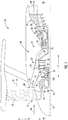
- FIG. 3 provides a cross sectional side view of the engine 10 including an exemplary embodiment of the shaft assembly 95.
- FIG. 4 provides a perspective view of the engine 10 including another exemplary embodiment of the shaft assembly 95.
- the coupling shaft 100 defines a plurality of coupling shaft teeth 105 extended in the axial direction A. Each coupling shaft tooth 105 is in circumferential arrangement along the coupling shaft 100.
- the coupling shaft 100 further includes a first material 103 and the plurality of coupling shaft teeth 105 each include a second material 104 different from the first material 103.
- the coupling shaft 100 may further define a first end 101 and a second end 102 along the axial direction A.
- the first end 101 is proximate to the engine core 20 and the second end 102 is proximate to the gearbox 45.
- the coupling shaft 100 is connected at the first end 101 to the engine core 20 and at the second end to the gearbox 45.
- the plurality of coupling shaft teeth 105 extend in the axial direction A from the second end 102 of the coupling shaft 100.
- the engine 10 and shaft assembly 95 further include a reference shaft 200 disposed inward of the coupling shaft 100 in the radial direction R.
- the reference shaft 200 extends in the axial direction A along the coupling shaft 100.
- the reference shaft 200 defines a plurality of reference shaft teeth 205 extended in the axial direction A and proximate to the plurality of coupling shaft teeth 105.
- Each reference shaft tooth 205 is in alternating circumferential arrangement relative to the plurality of coupling shaft teeth 105.
- the plurality of reference shaft teeth 205 are disposed to approximately the same circumference as the plurality of coupling shaft teeth 105 relative to the axial centerline 12.
- the plurality of reference shaft teeth 205 may extend at least partially in the axial direction A and at least partially in the radial direction R to define an approximately circumferentially adjacent arrangement relative to the plurality of coupling shaft teeth 105.
- the reference shaft 200 may include the first material 103.
- the reference shaft 200 may include a material other than the first or second material 103, 104, in which the other material defines a lower or weaker magnetic flux or magnetic flux density relative to the second material 104.
- the engine 10 and shaft assembly 95 may further include one or more spacers 150 disposed between the coupling shaft 100 and the reference shaft 200 along the radial direction R.
- the combination of the coupling shaft 100, the one or more spacers 150, and the reference shaft 200 may define a press fit or an interference fit arrangement such that the reference shaft 200 is positioned and/or retained relative to the spacer(s) 150 and the coupling shaft 100 by way of force exerted in the radial direction onto the coupling shaft 100.
- thermal differences may be used to assemble and retain the coupling shaft 100, the spacer(s) 150, and/or the reference shaft 200, such as applying heat to the coupling shaft 100 and/or the spacer 150, or such as removing heat from (i.e. cooling) the spacer(s) 150 and/or the reference shaft 200.
- the engine 10 further includes one or more torque sensors 140 disposed toward the plurality of coupling shaft teeth 105 and/or reference shaft teeth 205 along the radial direction R.
- the torque sensor 140 defines a rotary torque sensor configured to measure twist angle or phase shift of the coupling shaft 100 relative to the reference shaft 200.
- the one or more torque sensors 140 extend toward the plurality of teeth 105, 205 at an angle approximately perpendicular to the plurality of teeth 105, 205.
- the plurality of torque sensors 140 are in approximately equal circumferential spacing relative to the axial centerline 12.
- the engine 10 includes two torque sensors 140 spaced approximately 180 degrees apart relative to the axial centerline 12. In other embodiments, the plurality of torque sensors 140 may be placed in unequal circumferential arrangement relative to the axial centerline 12.
- the second material 104 is a permanent magnet material defining magnetic properties stronger than the first material 103.
- the second material 104 defines a ferromagnetic material.
- the second material 104 defines a magnetic flux greater than the first material 103.
- the second material 104 defines a magnetic flux density greater than the first material 103.
- the second material 104 defines a magnetic flux density greater than the first material 103 at an angle approximately perpendicular to the one or more torque sensors 140.
- the second material 104 defines a magnetic flux density greater than the first material at an angle approximately parallel to the one or more torque sensors 140 along the radial direction R.
- the second material 104 may be defined based at least on the torque sensor(s) 140 and/or a desired spacing in the radial direction R of the torque sensor(s) 140 relative to the plurality of teeth 105, 205.
- the second material 104 may define a greater magnetic flux or magnetic flux density such that the one or more torque sensors 140 may be placed more outward in the radial direction R from the plurality of teeth 105, 205.
- the plurality of coupling shaft teeth 105 and/or the plurality of reference shaft teeth 205 each define a cavity 106 into which the second material 104 is disposed.
- the second material 104 may be formed integral within the first material 103 of the coupling shaft 100 or the reference shaft 200.
- the coupling shaft 100 and/or the reference shaft 200 may be formed by way of additive manufacturing, in which the second material 104 is placed in the cavity 106 and the first material 103 is formed around the second material 104.
- the engine 10 may include a plurality of inserts 108 comprising the second material 104.
- the plurality of coupling shaft teeth 105 and/or the plurality of reference shaft teeth 205 may further define an outlet 107 at each cavity 106 disposed toward the second end 102.
- the plurality of inserts 108 may be disposed within each of the coupling shaft teeth 105 and/or each of the reference shaft teeth 205.
- the insert 108 may be disposed within the cavity 106 of each tooth 105, 05.
- the inserts 108 may be placed or removed from each cavity 106 through each outlet 107.
- the shaft assembly 95 including the coupling shaft 100, the reference shaft 200, and/or the spacers 150, in addition to other parts, components, or assemblies of the engine 10 shown and described in regard to FIGS. 1-4 may be formed of metals or composites appropriate for turbine engines including, but not limited to, iron-based, titanium-based, nickel-based, or cobalt-based alloys, each of which may include chromium, cobalt, tungsten, tantalum, molybdenum, and/or rhenium.
- the coupling shaft 100 may be formed using casting, forging, machining, or combinations thereof. Additionally, or alternatively, the coupling shaft 100 may be formed as a single unitary structure or an assembly of several components joined by one or more mechanical fasteners or joining processes, or combinations thereof.
- a volume of air as indicated schematically by arrows 90 enters the engine 10.
- a portion of the air as indicated schematically by arrows 91 is directed or routed outside of the engine core 20 to provide propulsion.
- another portion of air as indicated schematically by arrows 92 is directed or routed through an associated inlet 80 into the compressor section 21.
- the air 92 is progressively compressed as it flows through the compressor section 21, such as through the LPC 22 and the HPC 24, toward the combustion section 26.
- the now compressed air as indicated schematically by arrows 93 flows into the combustion section 26 where a fuel is introduced, mixed with at least a portion of the compressed air 93, and ignited to form combustion gases 94.
- the combustion gases 94 flow into the turbine section 31, causing rotary members of the turbine section 31 to rotate and support operation of respectively coupled rotary members in the compressor section 21 and/or fan or propeller assembly 14.
- the HPC 24 and the HPT 28 may be coupled and rotatable to drive the engine 10 and generate combustion gases 94 at the combustion section 26 to drive the LPT 30.
- the LPT 30 may be connected to the LPC 22.
- the coupling shaft 100 may be attached to the LPC 22 at the first end 101 and to the gearbox 45 at the second end 102.
- the flexible coupling 100 shaft may be attached to the HPC 24 at the first end 101.
- the coupling shaft 100 may be attached to the LPT 30 at the first end 101 and to the gearbox 45 at the second end 102.
- the coupling shaft 100 may be attached to the HPT 28 at the first end 101.
- the gearbox 45 may reduce the rotational speed from the engine core 20 (e.g. the compressor section 21 or the turbine section 31) and provide a desired amount of torque and rotational speed to the fan or propeller assembly 14.
Landscapes
- Engineering & Computer Science (AREA)
- General Engineering & Computer Science (AREA)
- Physics & Mathematics (AREA)
- Mechanical Engineering (AREA)
- Electromagnetism (AREA)
- Chemical & Material Sciences (AREA)
- Combustion & Propulsion (AREA)
- General Physics & Mathematics (AREA)
- Thermal Sciences (AREA)
- Turbine Rotor Nozzle Sealing (AREA)
- Structures Of Non-Positive Displacement Pumps (AREA)
Abstract
Description
- The project leading to this application has received funding from the Clean Sky 2 Joint Undertaking under the European Union's Horizon 2020 research and innovation program under grant agreement No. CS2-ENG-GAM-2014-2015-01.
- The present subject matter is generally related to turbine engines. More specifically, the subject matter is related to fan or propeller gearbox assemblies of turbine engines.
- Turbine engines are continually challenged to increase efficiencies related performance, fuel consumption, and noise output while generally maintaining or decreasing turbine engine packaging (e.g. axial or radial dimensions). Pursuant to meeting these challenges, turbine engines are incorporating different materials to reduce weight or size while providing similar or increased structural performance.
- Turbine engines may include a torque sensor to measure torque from a shaft of the engine. Torque sensor generally measure torque from a shaft of a specific type of material, thereby limiting the type of materials that may be used for a shaft. Consequently, turbine engines are at least partially limited by torque measurement requirements in regard to incorporating different materials to reduce weight or size of turbine engine shafts.
- Therefore, a need exists for a turbine engine that may overcome limitations of material types for turbine engine shafts due to torque measurement requirements.
- Aspects and advantages of the invention will be set forth in part in the following description, or may be obvious from the description, or may be learned through practice of the invention.
- The present disclosure is directed to a shaft assembly for a turbine engine, the shaft assembly defining an axial direction and a radial direction. The turbine engine includes a fan or propeller assembly and an engine core. The fan or propeller assembly includes a gearbox. The shaft assembly includes a coupling shaft defining a plurality of coupling shaft teeth extended in the axial direction. Each coupling shaft tooth is in circumferential arrangement along the coupling shaft. The coupling shaft includes a first material and the plurality of coupling shaft teeth include a second material different from the first material.
- In one embodiment, the coupling shaft further defines a first end and a second end along the axial direction. The first end is proximate to the engine core and the second end is proximate to the gearbox. The coupling shaft is connected to the engine core at the first end and to the gearbox at the second end. In another embodiment, the plurality of coupling shaft teeth extend in the axial direction from the second end of the coupling shaft.
- In various embodiments, the second material is a permanent magnet material. In one embodiment, the second material defines a magnetic flux greater than the first material.
- In another embodiment, the plurality of coupling shaft teeth each define a cavity and an outlet. In one embodiment, the plurality of coupling shaft teeth each include an insert disposed within the cavity. The insert comprises the second material in the plurality of coupling shaft teeth.
- In various embodiments, the shaft assembly may further include a reference shaft disposed inward of the coupling shaft in the radial direction, wherein the reference shaft extends in the axial direction along the coupling shaft. The reference shaft defines a plurality of reference shaft teeth extended in the axial direction and proximate to the plurality of coupling shaft teeth. Each reference shaft tooth is in alternating circumferential arrangement relative to the plurality of coupling shaft teeth. The plurality of reference shaft teeth each comprise the second material different from the first material.
- In one embodiment, the plurality of reference shaft teeth each further define a cavity and an outlet. In another embodiment, the plurality of reference shaft teeth each comprise an insert disposed within the cavity. The insert comprises the second material in the plurality of reference shaft teeth. In yet another embodiment, the plurality of reference shaft teeth are disposed to approximately the same circumference as the plurality of coupling shaft teeth. In still another embodiment, the shaft assembly further includes one or more spacers disposed in the radial direction between the coupling shaft and the reference shaft.
- In various embodiments, the shaft assembly further includes a torque sensor disposed toward the plurality of coupling shaft teeth in the radial direction. In one embodiment, the second material defines a magnetic flux density greater than the first material at an angle approximately perpendicular to the torque sensor. In another embodiment, the one or more torque sensors extend toward the plurality of coupling shaft teeth at an angle approximately perpendicular to the plurality of coupling shaft teeth.
- Another aspect of the present disclosure is directed to a turbine engine defining an axial direction and a radial direction. The turbine engine includes a fan or propeller assembly including a gearbox and a torque sensor disposed generally in the radial direction. The turbine engine further includes an engine core and a shaft assembly coupled at a first end to the engine core and at a second end to the gearbox of the fan or propeller assembly. The torque sensor is disposed proximate to the shaft assembly. The shaft assembly includes a coupling shaft defining a plurality of coupling shaft teeth extended in the axial direction, wherein each coupling shaft tooth is in circumferential arrangement along the coupling shaft, and further wherein the coupling shaft comprises a first material, and wherein the plurality of coupling shaft teeth further comprise a second material. The shaft assembly further includes a reference shaft disposed inward of the coupling shaft in the radial direction, wherein the reference shaft extends in the axial direction along the coupling shaft, and wherein the reference shaft defines a plurality of reference shaft teeth extended in the axial direction and proximate to the plurality of coupling shaft teeth, and wherein each reference shaft tooth is in alternating circumferential arrangement relative to the plurality of coupling shaft teeth.
- In various embodiments of the turbine engine, the plurality of coupling shaft teeth and/or the plurality of reference shaft teeth each define a cavity and an outlet. In one embodiment, the plurality of coupling shaft teeth and the plurality of reference shaft teeth each comprise an insert disposed within the cavity, and wherein the insert comprises the second material in each of the plurality of coupling shaft teeth and the plurality of reference shaft teeth.
- In one embodiment of the turbine engine, the second material defines a magnetic flux density greater than the first material at an angle approximately perpendicular to the torque sensor.
- In another embodiment of the turbine engine, the one or more torque sensors extend toward the plurality of coupling shaft teeth at an angle approximately perpendicular to the plurality of coupling shaft teeth.
- These and other features, aspects and advantages of the present invention will become better understood with reference to the following description and appended claims. The accompanying drawings, which are incorporated in and constitute a part of this specification, illustrate embodiments of the invention and, together with the description, serve to explain the principles of the invention.
- A full and enabling disclosure of the present invention, including the best mode thereof, directed to one of ordinary skill in the art, is set forth in the specification, which makes reference to the appended figures, in which:
-
FIG. 1 is a schematic cross sectional view of an exemplary embodiment of a turbine engine arrangement according to an aspect of the present disclosure; -
FIG. 2 is a schematic cross sectional view of another exemplary embodiment of a turbine engine arrangement according to an aspect of the present disclosure; -
FIG. 3 is a schematic cross sectional view of an exemplary embodiment of a coupling shaft connecting an exemplary gearbox and engine core; and -
FIG. 4 is a perspective view of another exemplary embodiment of a coupling shaft connecting an exemplary gearbox and engine core. - Repeat use of reference characters in the present specification and drawings is intended to represent the same or analogous features or elements of the present invention.
- Reference now will be made in detail to embodiments of the invention, one or more examples of which are illustrated in the drawings. Each example is provided by way of explanation of the invention, not limitation of the invention. In fact, it will be apparent to those skilled in the art that various modifications and variations can be made in the present invention without departing from the scope or spirit of the invention. For instance, features illustrated or described as part of one embodiment can be used with another embodiment to yield a still further embodiment. Thus, it is intended that the present invention covers such modifications and variations as come within the scope of the appended claims and their equivalents.
- As used herein, the terms "first", "second", and "third" may be used interchangeably to distinguish one component from another and are not intended to signify location or importance of the individual components.
- The terms "upstream" and "downstream" refer to the relative direction with respect to fluid flow in a fluid pathway. For example, "upstream" refers to the direction from which the fluid flows, and "downstream" refers to the direction to which the fluid flows.
- Turbine engine arrangements that may overcome limitations of material types for turbine engine shaft due to torque measurement requirements are generally provided. The turbine engine generally includes a fan or propeller assembly, including a gearbox, and an engine core. The gearbox and the engine core are connected by way of a coupling shaft defining a plurality of coupling shaft teeth extended in the axial direction. In various embodiments, the coupling shaft includes a first material and a second material different from the first material, in which the plurality of coupling shaft teeth includes the second material. In still various embodiments, the turbine engine includes a reference shaft defining a plurality of reference shaft teeth including the second material. Each shaft defines a cavity into which the second material is disposed in the plurality of coupling shaft teeth and reference shaft teeth.
- The embodiments of the present disclosure shown and described herein may remove limitations to shaft materials based at least on a torque measurement system. For example, the first material of the shaft may define a structurally appropriate first material including a lower or weaker magnetic flux or magnetic flux density relative to the second material that may be generally poorly suitable for an inductive torque sensor. Additionally, the second material of the shaft may define a higher magnetic flux or magnetic flux density that may be more appropriate for the inductive torque sensor while removing limitations due to structural performance requirements. Therefore, each shaft may define the first material with little or no regard for magnetic properties. For example, shaft materials may include non= ferromagnetic materials.
- Referring now to the drawings,
FIGS. 1 and2 are each schematic cross sectional views of an exemplary turbine engine 10 (herein referred to as "engine 10") according to an aspect of the present disclosure. InFIG. 1 , theengine 10 is shown as a high bypass turbofan engine, incorporating an aspect of the present disclosure. InFIG. 2 , theengine 10 is shown as a turboprop engine incorporating an aspect of the present disclosure. Although further described below with reference to a turbofan engine and/or a turboprop engine, the present disclosure is also applicable to wind turbines and turbomachinery in general, including propfan, turbojet, and turboshaft turbine engines, including marine and industrial turbine engines and auxiliary power units. As shown inFIGS. 1 and2 , theengine 10 has anaxial centerline axis 12 that extends there through for reference purposes. Theengine 10 defines an axial direction A, a radial direction R, and aforward end 99 and anaft end 98 along the axial direction A. - In general, the
engine 10 may include anengine core 20 and a fan orpropeller assembly 14. Theengine core 20 may generally include, in serial flow arrangement, acompressor section 21. acombustion section 26, and aturbine section 31. Thecompressor section 21 may define one or more compressors, such as a high pressure compressor (HPC) 24 and a low pressure compressor (LPC) 22. Theturbine section 31 may define one or more turbines, such as a high pressure turbine (HPT) 28 and a low pressure turbine (LPT) 30. In various embodiments, thecompressor section 21 may further include an intermediate pressure compressor (IPC). In still other embodiments, theturbine section 31 may further include an intermediate pressure turbine (IPT). - Each of the
compressors compressor section 21 and theturbines turbine section 31 may include one or more rotors 32. In one embodiment, therotors 32 include one ormore shafts 35 of theengine 10 connecting thecompressor section 21 to theturbine section 31. In other embodiments, therotors 32 generally define adisk 33 extended at least partially in the radial direction R and a plurality of airfoils connected in circumferentially adjacent arrangement and extended outward in the radial direction R from thedisk 33. The one ormore rotors 32 may each be connected together. For example, eachrotor 32 of theturbine section 31 or thecompressor section 21 may be connected by mechanical fasteners, such as bolts, nuts, or rivets, or by a bonding process, such as welding, friction bonding, diffusion bonding, etc. In various embodiments, one or more compressors of thecompressor section 21 may be drivingly connected and rotatable with one or more turbines of theturbine section 31 by way of one ormore drive shafts 35. - The fan or
propeller assembly 14 generally includes afan rotor 15. Thefan rotor 15 includes a plurality of fan orpropeller blades 42 that are coupled to and extend outwardly from thefan rotor 15 in the radial direction R. Thefan rotor 15 may extend in the axial direction A toward theforward end 99 from a reduction orpower gearbox 45. The fan orpropeller assembly 14 further includes ashaft assembly 95 including acoupling shaft 100 coupled to thegearbox 45 and extended toward theaft end 98 and coupled to theengine core 20. - In one embodiment, the
gearbox 45 may include agear train 50 including astar gear 52 and a plurality of planet gears 54. The plurality of planet gears 54 may each be fixed such that eachplanet gear 54 rotates on a fixed axis relative to thestar gear 52. Anannular gear 56 surrounds the plurality of planet gears 54 and rotates and transfers power and torque from thestar gear 52 through the plurality of planet gears 54. In one embodiment, thestar gear 52 may be attached to, unitary, or integral to thecoupling shaft 100. In various embodiments, thegearbox 45 may further include additional planet gears disposed radially between the plurality of planet gears 54 and thestar gear 52, or between the plurality of planet gears 54 and theannular gear 56. - Referring back to
FIGS. 1 and2 , thecoupling shaft 100 may define a generally hollow annular surface extended along the axial direction A. Thecoupling shaft 100 may be connected to theengine core 20 to transmit torque and power to thestar gear 52. Thefan rotor 15 may be connected to the surroundingannular gear 56 or the planet gears 54 to receive torque from thestar gear 52 and transfer torque to drive the fan orpropeller assembly 14. As power and torque are transmitted from theengine core 20, thegearbox 45 provides power and torque at an output speed to thefan rotor 15 more suitably adjusted for the fan orpropeller assembly 14. - Referring now to
FIGS. 3 and 4 , exemplary embodiments of a portion of theengine 10 including theshaft assembly 95 are provided.FIG. 3 provides a cross sectional side view of theengine 10 including an exemplary embodiment of theshaft assembly 95.FIG. 4 provides a perspective view of theengine 10 including another exemplary embodiment of theshaft assembly 95. Thecoupling shaft 100 defines a plurality ofcoupling shaft teeth 105 extended in the axial direction A. Eachcoupling shaft tooth 105 is in circumferential arrangement along thecoupling shaft 100. Thecoupling shaft 100 further includes afirst material 103 and the plurality ofcoupling shaft teeth 105 each include asecond material 104 different from thefirst material 103. - The
coupling shaft 100 may further define afirst end 101 and asecond end 102 along the axial direction A. In one embodiment, thefirst end 101 is proximate to theengine core 20 and thesecond end 102 is proximate to thegearbox 45. In various embodiments, thecoupling shaft 100 is connected at thefirst end 101 to theengine core 20 and at the second end to thegearbox 45. In the embodiment shown inFIG. 3 , the plurality ofcoupling shaft teeth 105 extend in the axial direction A from thesecond end 102 of thecoupling shaft 100. - Referring still to
FIGS. 3 and 4 , in various embodiments, theengine 10 andshaft assembly 95 further include areference shaft 200 disposed inward of thecoupling shaft 100 in the radial direction R. Thereference shaft 200 extends in the axial direction A along thecoupling shaft 100. Thereference shaft 200 defines a plurality ofreference shaft teeth 205 extended in the axial direction A and proximate to the plurality ofcoupling shaft teeth 105. Eachreference shaft tooth 205 is in alternating circumferential arrangement relative to the plurality ofcoupling shaft teeth 105. In one embodiment, the plurality ofreference shaft teeth 205 are disposed to approximately the same circumference as the plurality ofcoupling shaft teeth 105 relative to theaxial centerline 12. In various embodiments, the plurality ofreference shaft teeth 205 may extend at least partially in the axial direction A and at least partially in the radial direction R to define an approximately circumferentially adjacent arrangement relative to the plurality ofcoupling shaft teeth 105. In still other embodiments, thereference shaft 200 may include thefirst material 103. Alternatively, in yet other embodiments, thereference shaft 200 may include a material other than the first orsecond material second material 104. - As shown in
FIGS. 3 and 4 , theengine 10 andshaft assembly 95 may further include one ormore spacers 150 disposed between thecoupling shaft 100 and thereference shaft 200 along the radial direction R. The combination of thecoupling shaft 100, the one ormore spacers 150, and thereference shaft 200 may define a press fit or an interference fit arrangement such that thereference shaft 200 is positioned and/or retained relative to the spacer(s) 150 and thecoupling shaft 100 by way of force exerted in the radial direction onto thecoupling shaft 100. For example, thermal differences may be used to assemble and retain thecoupling shaft 100, the spacer(s) 150, and/or thereference shaft 200, such as applying heat to thecoupling shaft 100 and/or thespacer 150, or such as removing heat from (i.e. cooling) the spacer(s) 150 and/or thereference shaft 200. - Referring now to
FIG. 3 , in various embodiments theengine 10 further includes one ormore torque sensors 140 disposed toward the plurality ofcoupling shaft teeth 105 and/orreference shaft teeth 205 along the radial direction R. In one embodiment, thetorque sensor 140 defines a rotary torque sensor configured to measure twist angle or phase shift of thecoupling shaft 100 relative to thereference shaft 200. In various embodiments, the one ormore torque sensors 140 extend toward the plurality ofteeth teeth torque sensors 140, the plurality oftorque sensors 140 are in approximately equal circumferential spacing relative to theaxial centerline 12. In one embodiment, theengine 10 includes twotorque sensors 140 spaced approximately 180 degrees apart relative to theaxial centerline 12. In other embodiments, the plurality oftorque sensors 140 may be placed in unequal circumferential arrangement relative to theaxial centerline 12. - Referring back to
FIGS. 3 and 4 , in various embodiments, thesecond material 104 is a permanent magnet material defining magnetic properties stronger than thefirst material 103. In one embodiment, thesecond material 104 defines a ferromagnetic material. In other embodiments, thesecond material 104 defines a magnetic flux greater than thefirst material 103. In still other embodiments, thesecond material 104 defines a magnetic flux density greater than thefirst material 103. In one embodiment, thesecond material 104 defines a magnetic flux density greater than thefirst material 103 at an angle approximately perpendicular to the one ormore torque sensors 140. In another embodiment, thesecond material 104 defines a magnetic flux density greater than the first material at an angle approximately parallel to the one ormore torque sensors 140 along the radial direction R. In various embodiments, thesecond material 104 may be defined based at least on the torque sensor(s) 140 and/or a desired spacing in the radial direction R of the torque sensor(s) 140 relative to the plurality ofteeth second material 104 may define a greater magnetic flux or magnetic flux density such that the one ormore torque sensors 140 may be placed more outward in the radial direction R from the plurality ofteeth - Referring to
FIGS. 3 and 4 , in one embodiment, the plurality ofcoupling shaft teeth 105 and/or the plurality ofreference shaft teeth 205 each define acavity 106 into which thesecond material 104 is disposed. Thesecond material 104 may be formed integral within thefirst material 103 of thecoupling shaft 100 or thereference shaft 200. For example, thecoupling shaft 100 and/or thereference shaft 200 may be formed by way of additive manufacturing, in which thesecond material 104 is placed in thecavity 106 and thefirst material 103 is formed around thesecond material 104. - In other embodiments, such as shown in
FIG. 4 , theengine 10 may include a plurality ofinserts 108 comprising thesecond material 104. The plurality ofcoupling shaft teeth 105 and/or the plurality ofreference shaft teeth 205 may further define anoutlet 107 at eachcavity 106 disposed toward thesecond end 102. The plurality ofinserts 108 may be disposed within each of thecoupling shaft teeth 105 and/or each of thereference shaft teeth 205. In one embodiment, theinsert 108 may be disposed within thecavity 106 of eachtooth 105, 05. In various embodiments, theinserts 108 may be placed or removed from eachcavity 106 through eachoutlet 107. - The
shaft assembly 95, including thecoupling shaft 100, thereference shaft 200, and/or thespacers 150, in addition to other parts, components, or assemblies of theengine 10 shown and described in regard toFIGS. 1-4 may be formed of metals or composites appropriate for turbine engines including, but not limited to, iron-based, titanium-based, nickel-based, or cobalt-based alloys, each of which may include chromium, cobalt, tungsten, tantalum, molybdenum, and/or rhenium. Thecoupling shaft 100 may be formed using casting, forging, machining, or combinations thereof. Additionally, or alternatively, thecoupling shaft 100 may be formed as a single unitary structure or an assembly of several components joined by one or more mechanical fasteners or joining processes, or combinations thereof. - During operation of the
engine 10, as shown and described in regard toFIGS. 1-4 collectively, a volume of air as indicated schematically byarrows 90 enters theengine 10. As theair 90 passes across the fan orpropeller blades 42, a portion of the air as indicated schematically byarrows 91 is directed or routed outside of theengine core 20 to provide propulsion. Additionally, another portion of air as indicated schematically byarrows 92 is directed or routed through an associatedinlet 80 into thecompressor section 21. Theair 92 is progressively compressed as it flows through thecompressor section 21, such as through theLPC 22 and theHPC 24, toward thecombustion section 26. - The now compressed air as indicated schematically by
arrows 93 flows into thecombustion section 26 where a fuel is introduced, mixed with at least a portion of thecompressed air 93, and ignited to formcombustion gases 94. Thecombustion gases 94 flow into theturbine section 31, causing rotary members of theturbine section 31 to rotate and support operation of respectively coupled rotary members in thecompressor section 21 and/or fan orpropeller assembly 14. For example, theHPC 24 and theHPT 28 may be coupled and rotatable to drive theengine 10 and generatecombustion gases 94 at thecombustion section 26 to drive theLPT 30. TheLPT 30 may be connected to theLPC 22. Referring toFIG. 1 , thecoupling shaft 100 may be attached to theLPC 22 at thefirst end 101 and to thegearbox 45 at thesecond end 102. In other embodiments theflexible coupling 100 shaft may be attached to theHPC 24 at thefirst end 101. Referring toFIG. 2 , thecoupling shaft 100 may be attached to theLPT 30 at thefirst end 101 and to thegearbox 45 at thesecond end 102. In other embodiments thecoupling shaft 100 may be attached to theHPT 28 at thefirst end 101. Thegearbox 45 may reduce the rotational speed from the engine core 20 (e.g. thecompressor section 21 or the turbine section 31) and provide a desired amount of torque and rotational speed to the fan orpropeller assembly 14. - This written description uses examples to disclose the invention, including the best mode, and also to enable any person skilled in the art to practice the invention, including making and using any devices or systems and performing any incorporated methods. The patentable scope of the invention is defined by the claims, and may include other examples that occur to those skilled in the art. Such other examples are intended to be within the scope of the claims if they include structural elements that do not differ from the literal language of the claims, or if they include equivalent structural elements with insubstantial differences from the literal languages of the claims.
Claims (15)
- A shaft assembly (95) for a turbine engine (10), the shaft assembly (95) defining an axial direction and a radial direction, wherein the turbine engine (10) includes a fan or propeller assembly (14) and an engine core (20), and further wherein the fan or propeller assembly (14) includes a gearbox (45), the shaft assembly (95) comprising:a coupling shaft (100) defining a plurality of coupling shaft teeth (105) extended in the axial direction, wherein each coupling shaft tooth (105) is in circumferential arrangement along the coupling shaft (100), and further wherein the coupling shaft (100) comprises a first material (103), and wherein the plurality of coupling shaft teeth (105) comprise a second material (104) different from the first material (103).
- The shaft assembly (95) of claim 1, wherein the coupling shaft (100) further defines a first end (101) and a second end (102) along the axial direction, and wherein the first end (101) is proximate to the engine core (20) and the second end (102) is proximate to the gearbox (45), and wherein the coupling shaft (100) is connected to the engine core (20) at the first end (101) and to the gearbox (45) at the second end (102).
- The shaft assembly (95) of claim 2, wherein the plurality of coupling shaft teeth (105) extend in the axial direction from the second end (102) of the coupling shaft (100).
- The shaft assembly (95) of any one of claims 1 to 3, wherein the second material (104) is a permanent magnet material.
- The shaft assembly (95) of claim 4, wherein the second material (104) defines a magnetic flux greater than the first material (103).
- The shaft assembly (95) of any one of claims 1 to 5, wherein the plurality of coupling shaft teeth (105) each define a cavity (106) and an outlet (107).
- The shaft assembly (95) of claim 6, wherein the plurality of coupling shaft teeth (105) each comprise an insert (108) disposed within the cavity (106), and wherein the insert (108) comprises the second material (104) in the plurality of coupling shaft teeth (105).
- The shaft assembly (95) of any one of claims 1 to 7, further comprising:a reference shaft (200) disposed inward of the coupling shaft (100) in the radial direction, wherein the reference shaft (200) extends in the axial direction along the coupling shaft (100), and wherein the reference shaft (200) defines a plurality of reference shaft teeth (205) extended in the axial direction and proximate to the plurality of coupling shaft teeth (105), and wherein each reference shaft tooth (205) is in alternating circumferential arrangement relative to the plurality of coupling shaft teeth (105), and wherein the plurality of reference shaft teeth (205) each comprise the second material (104) different from the first material (103).
- The shaft assembly (95) of claim 8, wherein the plurality of reference shaft teeth (205) each define a cavity (106) and an outlet (107).
- The shaft assembly (95) of claim 9, wherein the plurality of reference shaft teeth (205) each comprise an insert (108) disposed within the cavity (106), and wherein the insert (108) comprises the second material (104) in the plurality of reference shaft teeth (205).
- The shaft assembly (95) of claim 8, wherein the plurality of reference shaft teeth (205) are disposed to approximately the same circumference as the plurality of coupling shaft teeth (105).
- The shaft assembly (95) of claim 8, further comprising:one or more spacers (150) disposed in the radial direction between the coupling shaft (100) and the reference shaft (200).
- The shaft assembly (95) of any one of claims 1 to 12, further comprising:a torque sensor (140) disposed toward the plurality of coupling shaft teeth (105) in the radial direction.
- The shaft assembly (95) of claim 13, wherein the second material (104) defines a magnetic flux density greater than the first material (103) at an angle approximately perpendicular to the torque sensor (140).
- The shaft assembly (95) of claim 13, wherein the one or more torque sensors (140) extend toward the plurality of coupling shaft teeth (105) at an angle approximately perpendicular to the plurality of coupling shaft teeth (105).
Priority Applications (6)
| Application Number | Priority Date | Filing Date | Title |
|---|---|---|---|
| EP17425006.8A EP3354860B1 (en) | 2017-01-30 | 2017-01-30 | Magnetic torque metering system |
| CA3050330A CA3050330A1 (en) | 2017-01-30 | 2018-01-26 | Magnetic torque metering system |
| US16/482,011 US11204087B2 (en) | 2017-01-30 | 2018-01-26 | Magnetic torque metering system |
| CN201880008945.4A CN110234842B (en) | 2017-01-30 | 2018-01-26 | Magnetic torque metering system |
| JP2019541132A JP2020507706A (en) | 2017-01-30 | 2018-01-26 | Magnetic torque measurement system |
| PCT/EP2018/052007 WO2018138291A1 (en) | 2017-01-30 | 2018-01-26 | Magnetic torque metering system |
Applications Claiming Priority (1)
| Application Number | Priority Date | Filing Date | Title |
|---|---|---|---|
| EP17425006.8A EP3354860B1 (en) | 2017-01-30 | 2017-01-30 | Magnetic torque metering system |
Publications (2)
| Publication Number | Publication Date |
|---|---|
| EP3354860A1 true EP3354860A1 (en) | 2018-08-01 |
| EP3354860B1 EP3354860B1 (en) | 2020-05-06 |
Family
ID=58266536
Family Applications (1)
| Application Number | Title | Priority Date | Filing Date |
|---|---|---|---|
| EP17425006.8A Active EP3354860B1 (en) | 2017-01-30 | 2017-01-30 | Magnetic torque metering system |
Country Status (6)
| Country | Link |
|---|---|
| US (1) | US11204087B2 (en) |
| EP (1) | EP3354860B1 (en) |
| JP (1) | JP2020507706A (en) |
| CN (1) | CN110234842B (en) |
| CA (1) | CA3050330A1 (en) |
| WO (1) | WO2018138291A1 (en) |
Families Citing this family (4)
| Publication number | Priority date | Publication date | Assignee | Title |
|---|---|---|---|---|
| EP3354860B1 (en) | 2017-01-30 | 2020-05-06 | Ge Avio S.r.l. | Magnetic torque metering system |
| IT202100018935A1 (en) * | 2021-07-16 | 2023-01-16 | Ge Avio Srl | DAMPER SYSTEM FOR AN ENGINE SHAFT |
| FR3136449B1 (en) * | 2022-06-08 | 2024-05-10 | Airbus Helicopters | mechanical drive device fitted with a tone wheel torque meter, power transmission box fitted with such a mechanical drive device and aircraft |
| US20250224289A1 (en) * | 2024-01-05 | 2025-07-10 | Pratt & Whitney Canada Corp. | Torque measurement system for aircraft engines |
Citations (4)
| Publication number | Priority date | Publication date | Assignee | Title |
|---|---|---|---|---|
| DE19817886A1 (en) * | 1998-04-22 | 1999-10-28 | Bosch Gmbh Robert | Arrangement for detecting torque acting on shaft |
| US20040050178A1 (en) * | 2002-09-13 | 2004-03-18 | Gastops Ltd. | Apparatus for detecting torque, axial position and axial alignment of a rotating shaft |
| FR3017657A1 (en) * | 2014-02-19 | 2015-08-21 | Snecma | TORSION DISK TORQUE MEASURING DEVICE FOR TURBOMACHINE |
| EP3109409A1 (en) * | 2015-06-23 | 2016-12-28 | General Electric Company | Relative position measurement |
Family Cites Families (16)
| Publication number | Priority date | Publication date | Assignee | Title |
|---|---|---|---|---|
| US3190113A (en) | 1962-11-28 | 1965-06-22 | Kaman Aircraft Corp | Electro-mechanical torque sensing device and method |
| FR2716002B1 (en) | 1994-02-08 | 1996-04-19 | Omahony Gerard | Magnetic torque meter for absolute torque and torque measurements. |
| TW200506241A (en) * | 2003-08-08 | 2005-02-16 | Yong-Han Liu | Non-contact wheel-type transmitting device |
| DE102004039314A1 (en) | 2004-08-13 | 2006-02-23 | Mtu Aero Engines Gmbh | Apparatus and method for determining torques on a turbine shaft |
| JP2007279003A (en) | 2006-04-12 | 2007-10-25 | Matsushita Electric Ind Co Ltd | Rotation angle and torque detection device and manufacturing method thereof |
| GB2481414B (en) | 2010-06-22 | 2012-09-19 | Weston Aerospace Ltd | Speed or torque probe for gas turbine engines |
| IT1401665B1 (en) | 2010-08-31 | 2013-08-02 | Nuova Pignone S R L | DRIVING SYSTEM FOR TURBOMACHINE AND METHOD. |
| JP5756376B2 (en) * | 2011-03-18 | 2015-07-29 | カヤバ工業株式会社 | Torque sensor |
| DE102011052043B4 (en) | 2011-07-21 | 2022-06-09 | Bourns, Inc. | Angle of rotation and torsion angle sensor |
| DE102011121842A1 (en) | 2011-12-21 | 2013-06-27 | Robert Bosch Gmbh | Device for measuring torque, direction of rotation and Drehverwidigkeit a shaft of a transmission, in particular an output shaft of an azimuth gear of a wind turbine |
| JP5675700B2 (en) * | 2012-05-25 | 2015-02-25 | 株式会社日本自動車部品総合研究所 | Torque sensor |
| FR2995018B1 (en) | 2012-09-06 | 2014-09-12 | Snecma | TURBOMACHINE COMPRISING MEANS FOR MEASURING THE SPEED AND TORSION TORQUE OF A TURBOMACHINE SHAFT AND METHOD OF MONITORING SAID TREE |
| DE102013101791A1 (en) | 2013-02-22 | 2014-08-28 | Rolls-Royce Deutschland Ltd & Co Kg | Aircraft gas turbine with a first rotatable shaft |
| GB201412473D0 (en) | 2014-07-14 | 2014-08-27 | Rolls Royce Plc | Shaft stiffness |
| US20160178464A1 (en) | 2014-12-19 | 2016-06-23 | Rolls-Royce Corporation | Torque sensor monitoring for gas turbine engine |
| EP3354860B1 (en) | 2017-01-30 | 2020-05-06 | Ge Avio S.r.l. | Magnetic torque metering system |
-
2017
- 2017-01-30 EP EP17425006.8A patent/EP3354860B1/en active Active
-
2018
- 2018-01-26 JP JP2019541132A patent/JP2020507706A/en active Pending
- 2018-01-26 WO PCT/EP2018/052007 patent/WO2018138291A1/en not_active Ceased
- 2018-01-26 CA CA3050330A patent/CA3050330A1/en not_active Abandoned
- 2018-01-26 CN CN201880008945.4A patent/CN110234842B/en active Active
- 2018-01-26 US US16/482,011 patent/US11204087B2/en active Active
Patent Citations (4)
| Publication number | Priority date | Publication date | Assignee | Title |
|---|---|---|---|---|
| DE19817886A1 (en) * | 1998-04-22 | 1999-10-28 | Bosch Gmbh Robert | Arrangement for detecting torque acting on shaft |
| US20040050178A1 (en) * | 2002-09-13 | 2004-03-18 | Gastops Ltd. | Apparatus for detecting torque, axial position and axial alignment of a rotating shaft |
| FR3017657A1 (en) * | 2014-02-19 | 2015-08-21 | Snecma | TORSION DISK TORQUE MEASURING DEVICE FOR TURBOMACHINE |
| EP3109409A1 (en) * | 2015-06-23 | 2016-12-28 | General Electric Company | Relative position measurement |
Also Published As
| Publication number | Publication date |
|---|---|
| EP3354860B1 (en) | 2020-05-06 |
| WO2018138291A1 (en) | 2018-08-02 |
| JP2020507706A (en) | 2020-03-12 |
| CA3050330A1 (en) | 2018-08-02 |
| US20200003290A1 (en) | 2020-01-02 |
| CN110234842A (en) | 2019-09-13 |
| CN110234842B (en) | 2022-01-11 |
| US11204087B2 (en) | 2021-12-21 |
Similar Documents
| Publication | Publication Date | Title |
|---|---|---|
| US10823114B2 (en) | Counter rotating turbine with reversing reduction gearbox | |
| EP3404214B1 (en) | Blade outer air seal assembly and gas turbine engine with such an assembly | |
| CN110234839B (en) | Flexible coupling shafts for turbine engines | |
| CN110268147B (en) | Method and system for connecting a turbine engine gearbox to an engine core | |
| CN110199091B (en) | Dual spool gas turbine engine with staggered turbine sections | |
| CN110573697B (en) | Turbine frame and bearing arrangement for a three-shaft engine | |
| US10815881B2 (en) | Counter rotating turbine with reversing speed reduction assembly | |
| US11204087B2 (en) | Magnetic torque metering system | |
| US10544793B2 (en) | Thermal isolation structure for rotating turbine frame | |
| EP3415728A1 (en) | Gas turbine engine with rotating reversing compound gearbox | |
| EP3051072B1 (en) | Airfoil module | |
| EP3081748B1 (en) | Gas turbine engine system comprising a seal ring | |
| CN112431674A (en) | Counter-rotating turbine with reversing reduction gearbox | |
| EP3663538A1 (en) | Rotor overspeed protection assembly | |
| CN115450952B (en) | Compressor with counter-rotating blade row |
Legal Events
| Date | Code | Title | Description |
|---|---|---|---|
| PUAI | Public reference made under article 153(3) epc to a published international application that has entered the european phase |
Free format text: ORIGINAL CODE: 0009012 |
|
| STAA | Information on the status of an ep patent application or granted ep patent |
Free format text: STATUS: THE APPLICATION HAS BEEN PUBLISHED |
|
| AK | Designated contracting states |
Kind code of ref document: A1 Designated state(s): AL AT BE BG CH CY CZ DE DK EE ES FI FR GB GR HR HU IE IS IT LI LT LU LV MC MK MT NL NO PL PT RO RS SE SI SK SM TR |
|
| AX | Request for extension of the european patent |
Extension state: BA ME |
|
| STAA | Information on the status of an ep patent application or granted ep patent |
Free format text: STATUS: REQUEST FOR EXAMINATION WAS MADE |
|
| 17P | Request for examination filed |
Effective date: 20190201 |
|
| RBV | Designated contracting states (corrected) |
Designated state(s): AL AT BE BG CH CY CZ DE DK EE ES FI FR GB GR HR HU IE IS IT LI LT LU LV MC MK MT NL NO PL PT RO RS SE SI SK SM TR |
|
| GRAP | Despatch of communication of intention to grant a patent |
Free format text: ORIGINAL CODE: EPIDOSNIGR1 |
|
| STAA | Information on the status of an ep patent application or granted ep patent |
Free format text: STATUS: GRANT OF PATENT IS INTENDED |
|
| RIC1 | Information provided on ipc code assigned before grant |
Ipc: F01D 17/04 20060101AFI20191028BHEP Ipc: F02C 3/107 20060101ALI20191028BHEP Ipc: G01L 3/10 20060101ALI20191028BHEP Ipc: G01L 3/14 20060101ALI20191028BHEP |
|
| INTG | Intention to grant announced |
Effective date: 20191128 |
|
| GRAS | Grant fee paid |
Free format text: ORIGINAL CODE: EPIDOSNIGR3 |
|
| GRAA | (expected) grant |
Free format text: ORIGINAL CODE: 0009210 |
|
| STAA | Information on the status of an ep patent application or granted ep patent |
Free format text: STATUS: THE PATENT HAS BEEN GRANTED |
|
| AK | Designated contracting states |
Kind code of ref document: B1 Designated state(s): AL AT BE BG CH CY CZ DE DK EE ES FI FR GB GR HR HU IE IS IT LI LT LU LV MC MK MT NL NO PL PT RO RS SE SI SK SM TR |
|
| REG | Reference to a national code |
Ref country code: GB Ref legal event code: FG4D |
|
| REG | Reference to a national code |
Ref country code: AT Ref legal event code: REF Ref document number: 1267045 Country of ref document: AT Kind code of ref document: T Effective date: 20200515 Ref country code: CH Ref legal event code: EP |
|
| REG | Reference to a national code |
Ref country code: IE Ref legal event code: FG4D |
|
| REG | Reference to a national code |
Ref country code: DE Ref legal event code: R096 Ref document number: 602017016179 Country of ref document: DE |
|
| REG | Reference to a national code |
Ref country code: LT Ref legal event code: MG4D |
|
| REG | Reference to a national code |
Ref country code: NL Ref legal event code: MP Effective date: 20200506 |
|
| PG25 | Lapsed in a contracting state [announced via postgrant information from national office to epo] |
Ref country code: NO Free format text: LAPSE BECAUSE OF FAILURE TO SUBMIT A TRANSLATION OF THE DESCRIPTION OR TO PAY THE FEE WITHIN THE PRESCRIBED TIME-LIMIT Effective date: 20200806 Ref country code: GR Free format text: LAPSE BECAUSE OF FAILURE TO SUBMIT A TRANSLATION OF THE DESCRIPTION OR TO PAY THE FEE WITHIN THE PRESCRIBED TIME-LIMIT Effective date: 20200807 Ref country code: SE Free format text: LAPSE BECAUSE OF FAILURE TO SUBMIT A TRANSLATION OF THE DESCRIPTION OR TO PAY THE FEE WITHIN THE PRESCRIBED TIME-LIMIT Effective date: 20200506 Ref country code: LT Free format text: LAPSE BECAUSE OF FAILURE TO SUBMIT A TRANSLATION OF THE DESCRIPTION OR TO PAY THE FEE WITHIN THE PRESCRIBED TIME-LIMIT Effective date: 20200506 Ref country code: PT Free format text: LAPSE BECAUSE OF FAILURE TO SUBMIT A TRANSLATION OF THE DESCRIPTION OR TO PAY THE FEE WITHIN THE PRESCRIBED TIME-LIMIT Effective date: 20200907 Ref country code: FI Free format text: LAPSE BECAUSE OF FAILURE TO SUBMIT A TRANSLATION OF THE DESCRIPTION OR TO PAY THE FEE WITHIN THE PRESCRIBED TIME-LIMIT Effective date: 20200506 Ref country code: IS Free format text: LAPSE BECAUSE OF FAILURE TO SUBMIT A TRANSLATION OF THE DESCRIPTION OR TO PAY THE FEE WITHIN THE PRESCRIBED TIME-LIMIT Effective date: 20200906 |
|
| PG25 | Lapsed in a contracting state [announced via postgrant information from national office to epo] |
Ref country code: HR Free format text: LAPSE BECAUSE OF FAILURE TO SUBMIT A TRANSLATION OF THE DESCRIPTION OR TO PAY THE FEE WITHIN THE PRESCRIBED TIME-LIMIT Effective date: 20200506 Ref country code: RS Free format text: LAPSE BECAUSE OF FAILURE TO SUBMIT A TRANSLATION OF THE DESCRIPTION OR TO PAY THE FEE WITHIN THE PRESCRIBED TIME-LIMIT Effective date: 20200506 Ref country code: LV Free format text: LAPSE BECAUSE OF FAILURE TO SUBMIT A TRANSLATION OF THE DESCRIPTION OR TO PAY THE FEE WITHIN THE PRESCRIBED TIME-LIMIT Effective date: 20200506 Ref country code: BG Free format text: LAPSE BECAUSE OF FAILURE TO SUBMIT A TRANSLATION OF THE DESCRIPTION OR TO PAY THE FEE WITHIN THE PRESCRIBED TIME-LIMIT Effective date: 20200806 |
|
| REG | Reference to a national code |
Ref country code: AT Ref legal event code: MK05 Ref document number: 1267045 Country of ref document: AT Kind code of ref document: T Effective date: 20200506 |
|
| PG25 | Lapsed in a contracting state [announced via postgrant information from national office to epo] |
Ref country code: NL Free format text: LAPSE BECAUSE OF FAILURE TO SUBMIT A TRANSLATION OF THE DESCRIPTION OR TO PAY THE FEE WITHIN THE PRESCRIBED TIME-LIMIT Effective date: 20200506 Ref country code: AL Free format text: LAPSE BECAUSE OF FAILURE TO SUBMIT A TRANSLATION OF THE DESCRIPTION OR TO PAY THE FEE WITHIN THE PRESCRIBED TIME-LIMIT Effective date: 20200506 |
|
| PG25 | Lapsed in a contracting state [announced via postgrant information from national office to epo] |
Ref country code: ES Free format text: LAPSE BECAUSE OF FAILURE TO SUBMIT A TRANSLATION OF THE DESCRIPTION OR TO PAY THE FEE WITHIN THE PRESCRIBED TIME-LIMIT Effective date: 20200506 Ref country code: CZ Free format text: LAPSE BECAUSE OF FAILURE TO SUBMIT A TRANSLATION OF THE DESCRIPTION OR TO PAY THE FEE WITHIN THE PRESCRIBED TIME-LIMIT Effective date: 20200506 Ref country code: SM Free format text: LAPSE BECAUSE OF FAILURE TO SUBMIT A TRANSLATION OF THE DESCRIPTION OR TO PAY THE FEE WITHIN THE PRESCRIBED TIME-LIMIT Effective date: 20200506 Ref country code: AT Free format text: LAPSE BECAUSE OF FAILURE TO SUBMIT A TRANSLATION OF THE DESCRIPTION OR TO PAY THE FEE WITHIN THE PRESCRIBED TIME-LIMIT Effective date: 20200506 Ref country code: IT Free format text: LAPSE BECAUSE OF FAILURE TO SUBMIT A TRANSLATION OF THE DESCRIPTION OR TO PAY THE FEE WITHIN THE PRESCRIBED TIME-LIMIT Effective date: 20200506 Ref country code: RO Free format text: LAPSE BECAUSE OF FAILURE TO SUBMIT A TRANSLATION OF THE DESCRIPTION OR TO PAY THE FEE WITHIN THE PRESCRIBED TIME-LIMIT Effective date: 20200506 Ref country code: DK Free format text: LAPSE BECAUSE OF FAILURE TO SUBMIT A TRANSLATION OF THE DESCRIPTION OR TO PAY THE FEE WITHIN THE PRESCRIBED TIME-LIMIT Effective date: 20200506 Ref country code: EE Free format text: LAPSE BECAUSE OF FAILURE TO SUBMIT A TRANSLATION OF THE DESCRIPTION OR TO PAY THE FEE WITHIN THE PRESCRIBED TIME-LIMIT Effective date: 20200506 |
|
| REG | Reference to a national code |
Ref country code: DE Ref legal event code: R097 Ref document number: 602017016179 Country of ref document: DE |
|
| PG25 | Lapsed in a contracting state [announced via postgrant information from national office to epo] |
Ref country code: SK Free format text: LAPSE BECAUSE OF FAILURE TO SUBMIT A TRANSLATION OF THE DESCRIPTION OR TO PAY THE FEE WITHIN THE PRESCRIBED TIME-LIMIT Effective date: 20200506 Ref country code: PL Free format text: LAPSE BECAUSE OF FAILURE TO SUBMIT A TRANSLATION OF THE DESCRIPTION OR TO PAY THE FEE WITHIN THE PRESCRIBED TIME-LIMIT Effective date: 20200506 |
|
| PLBE | No opposition filed within time limit |
Free format text: ORIGINAL CODE: 0009261 |
|
| STAA | Information on the status of an ep patent application or granted ep patent |
Free format text: STATUS: NO OPPOSITION FILED WITHIN TIME LIMIT |
|
| 26N | No opposition filed |
Effective date: 20210209 |
|
| PG25 | Lapsed in a contracting state [announced via postgrant information from national office to epo] |
Ref country code: SI Free format text: LAPSE BECAUSE OF FAILURE TO SUBMIT A TRANSLATION OF THE DESCRIPTION OR TO PAY THE FEE WITHIN THE PRESCRIBED TIME-LIMIT Effective date: 20200506 |
|
| PG25 | Lapsed in a contracting state [announced via postgrant information from national office to epo] |
Ref country code: MC Free format text: LAPSE BECAUSE OF FAILURE TO SUBMIT A TRANSLATION OF THE DESCRIPTION OR TO PAY THE FEE WITHIN THE PRESCRIBED TIME-LIMIT Effective date: 20200506 |
|
| REG | Reference to a national code |
Ref country code: CH Ref legal event code: PL |
|
| PG25 | Lapsed in a contracting state [announced via postgrant information from national office to epo] |
Ref country code: LU Free format text: LAPSE BECAUSE OF NON-PAYMENT OF DUE FEES Effective date: 20210130 |
|
| REG | Reference to a national code |
Ref country code: BE Ref legal event code: MM Effective date: 20210131 |
|
| PG25 | Lapsed in a contracting state [announced via postgrant information from national office to epo] |
Ref country code: CH Free format text: LAPSE BECAUSE OF NON-PAYMENT OF DUE FEES Effective date: 20210131 Ref country code: LI Free format text: LAPSE BECAUSE OF NON-PAYMENT OF DUE FEES Effective date: 20210131 |
|
| PG25 | Lapsed in a contracting state [announced via postgrant information from national office to epo] |
Ref country code: IE Free format text: LAPSE BECAUSE OF NON-PAYMENT OF DUE FEES Effective date: 20210130 |
|
| PG25 | Lapsed in a contracting state [announced via postgrant information from national office to epo] |
Ref country code: BE Free format text: LAPSE BECAUSE OF NON-PAYMENT OF DUE FEES Effective date: 20210131 |
|
| P01 | Opt-out of the competence of the unified patent court (upc) registered |
Effective date: 20230418 |
|
| PG25 | Lapsed in a contracting state [announced via postgrant information from national office to epo] |
Ref country code: CY Free format text: LAPSE BECAUSE OF FAILURE TO SUBMIT A TRANSLATION OF THE DESCRIPTION OR TO PAY THE FEE WITHIN THE PRESCRIBED TIME-LIMIT Effective date: 20200506 |
|
| PG25 | Lapsed in a contracting state [announced via postgrant information from national office to epo] |
Ref country code: HU Free format text: LAPSE BECAUSE OF FAILURE TO SUBMIT A TRANSLATION OF THE DESCRIPTION OR TO PAY THE FEE WITHIN THE PRESCRIBED TIME-LIMIT; INVALID AB INITIO Effective date: 20170130 |
|
| PG25 | Lapsed in a contracting state [announced via postgrant information from national office to epo] |
Ref country code: MK Free format text: LAPSE BECAUSE OF FAILURE TO SUBMIT A TRANSLATION OF THE DESCRIPTION OR TO PAY THE FEE WITHIN THE PRESCRIBED TIME-LIMIT Effective date: 20200506 |
|
| PG25 | Lapsed in a contracting state [announced via postgrant information from national office to epo] |
Ref country code: MT Free format text: LAPSE BECAUSE OF FAILURE TO SUBMIT A TRANSLATION OF THE DESCRIPTION OR TO PAY THE FEE WITHIN THE PRESCRIBED TIME-LIMIT Effective date: 20200506 |
|
| PG25 | Lapsed in a contracting state [announced via postgrant information from national office to epo] |
Ref country code: TR Free format text: LAPSE BECAUSE OF FAILURE TO SUBMIT A TRANSLATION OF THE DESCRIPTION OR TO PAY THE FEE WITHIN THE PRESCRIBED TIME-LIMIT Effective date: 20200506 |
|
| PGFP | Annual fee paid to national office [announced via postgrant information from national office to epo] |
Ref country code: GB Payment date: 20251217 Year of fee payment: 10 |
|
| PGFP | Annual fee paid to national office [announced via postgrant information from national office to epo] |
Ref country code: FR Payment date: 20251218 Year of fee payment: 10 |
|
| PGFP | Annual fee paid to national office [announced via postgrant information from national office to epo] |
Ref country code: DE Payment date: 20251217 Year of fee payment: 10 |