EP3354506A2 - Hydraulic drive system - Google Patents
Hydraulic drive system Download PDFInfo
- Publication number
- EP3354506A2 EP3354506A2 EP18150656.9A EP18150656A EP3354506A2 EP 3354506 A2 EP3354506 A2 EP 3354506A2 EP 18150656 A EP18150656 A EP 18150656A EP 3354506 A2 EP3354506 A2 EP 3354506A2
- Authority
- EP
- European Patent Office
- Prior art keywords
- actuator
- motor
- rotor
- engagement
- assembly
- Prior art date
- Legal status (The legal status is an assumption and is not a legal conclusion. Google has not performed a legal analysis and makes no representation as to the accuracy of the status listed.)
- Granted
Links
Images






Classifications
-
- B—PERFORMING OPERATIONS; TRANSPORTING
- B62—LAND VEHICLES FOR TRAVELLING OTHERWISE THAN ON RAILS
- B62D—MOTOR VEHICLES; TRAILERS
- B62D59/00—Trailers with driven ground wheels or the like
- B62D59/04—Trailers with driven ground wheels or the like driven from propulsion unit on trailer
-
- B—PERFORMING OPERATIONS; TRANSPORTING
- B60—VEHICLES IN GENERAL
- B60K—ARRANGEMENT OR MOUNTING OF PROPULSION UNITS OR OF TRANSMISSIONS IN VEHICLES; ARRANGEMENT OR MOUNTING OF PLURAL DIVERSE PRIME-MOVERS IN VEHICLES; AUXILIARY DRIVES FOR VEHICLES; INSTRUMENTATION OR DASHBOARDS FOR VEHICLES; ARRANGEMENTS IN CONNECTION WITH COOLING, AIR INTAKE, GAS EXHAUST OR FUEL SUPPLY OF PROPULSION UNITS IN VEHICLES
- B60K17/00—Arrangement or mounting of transmissions in vehicles
- B60K17/04—Arrangement or mounting of transmissions in vehicles characterised by arrangement, location or kind of gearing
- B60K17/043—Transmission unit disposed in on near the vehicle wheel, or between the differential gear unit and the wheel
- B60K17/046—Transmission unit disposed in on near the vehicle wheel, or between the differential gear unit and the wheel with planetary gearing having orbital motion
-
- B—PERFORMING OPERATIONS; TRANSPORTING
- B60—VEHICLES IN GENERAL
- B60K—ARRANGEMENT OR MOUNTING OF PROPULSION UNITS OR OF TRANSMISSIONS IN VEHICLES; ARRANGEMENT OR MOUNTING OF PLURAL DIVERSE PRIME-MOVERS IN VEHICLES; AUXILIARY DRIVES FOR VEHICLES; INSTRUMENTATION OR DASHBOARDS FOR VEHICLES; ARRANGEMENTS IN CONNECTION WITH COOLING, AIR INTAKE, GAS EXHAUST OR FUEL SUPPLY OF PROPULSION UNITS IN VEHICLES
- B60K7/00—Disposition of motor in, or adjacent to, traction wheel
- B60K7/0015—Disposition of motor in, or adjacent to, traction wheel the motor being hydraulic
-
- B—PERFORMING OPERATIONS; TRANSPORTING
- B60—VEHICLES IN GENERAL
- B60K—ARRANGEMENT OR MOUNTING OF PROPULSION UNITS OR OF TRANSMISSIONS IN VEHICLES; ARRANGEMENT OR MOUNTING OF PLURAL DIVERSE PRIME-MOVERS IN VEHICLES; AUXILIARY DRIVES FOR VEHICLES; INSTRUMENTATION OR DASHBOARDS FOR VEHICLES; ARRANGEMENTS IN CONNECTION WITH COOLING, AIR INTAKE, GAS EXHAUST OR FUEL SUPPLY OF PROPULSION UNITS IN VEHICLES
- B60K8/00—Arrangement or mounting of propulsion units not provided for in one of main groups B60K1/00 - B60K7/00
-
- F—MECHANICAL ENGINEERING; LIGHTING; HEATING; WEAPONS; BLASTING
- F16—ENGINEERING ELEMENTS AND UNITS; GENERAL MEASURES FOR PRODUCING AND MAINTAINING EFFECTIVE FUNCTIONING OF MACHINES OR INSTALLATIONS; THERMAL INSULATION IN GENERAL
- F16D—COUPLINGS FOR TRANSMITTING ROTATION; CLUTCHES; BRAKES
- F16D11/00—Clutches in which the members have interengaging parts
- F16D11/14—Clutches in which the members have interengaging parts with clutching members movable only axially
-
- B—PERFORMING OPERATIONS; TRANSPORTING
- B60—VEHICLES IN GENERAL
- B60K—ARRANGEMENT OR MOUNTING OF PROPULSION UNITS OR OF TRANSMISSIONS IN VEHICLES; ARRANGEMENT OR MOUNTING OF PLURAL DIVERSE PRIME-MOVERS IN VEHICLES; AUXILIARY DRIVES FOR VEHICLES; INSTRUMENTATION OR DASHBOARDS FOR VEHICLES; ARRANGEMENTS IN CONNECTION WITH COOLING, AIR INTAKE, GAS EXHAUST OR FUEL SUPPLY OF PROPULSION UNITS IN VEHICLES
- B60K7/00—Disposition of motor in, or adjacent to, traction wheel
- B60K2007/0038—Disposition of motor in, or adjacent to, traction wheel the motor moving together with the wheel axle
-
- B—PERFORMING OPERATIONS; TRANSPORTING
- B60—VEHICLES IN GENERAL
- B60K—ARRANGEMENT OR MOUNTING OF PROPULSION UNITS OR OF TRANSMISSIONS IN VEHICLES; ARRANGEMENT OR MOUNTING OF PLURAL DIVERSE PRIME-MOVERS IN VEHICLES; AUXILIARY DRIVES FOR VEHICLES; INSTRUMENTATION OR DASHBOARDS FOR VEHICLES; ARRANGEMENTS IN CONNECTION WITH COOLING, AIR INTAKE, GAS EXHAUST OR FUEL SUPPLY OF PROPULSION UNITS IN VEHICLES
- B60K7/00—Disposition of motor in, or adjacent to, traction wheel
- B60K2007/0092—Disposition of motor in, or adjacent to, traction wheel the motor axle being coaxial to the wheel axle
-
- B—PERFORMING OPERATIONS; TRANSPORTING
- B60—VEHICLES IN GENERAL
- B60Y—INDEXING SCHEME RELATING TO ASPECTS CROSS-CUTTING VEHICLE TECHNOLOGY
- B60Y2200/00—Type of vehicle
- B60Y2200/10—Road Vehicles
- B60Y2200/14—Trucks; Load vehicles, Busses
- B60Y2200/147—Trailers, e.g. full trailers or caravans
-
- B—PERFORMING OPERATIONS; TRANSPORTING
- B60—VEHICLES IN GENERAL
- B60Y—INDEXING SCHEME RELATING TO ASPECTS CROSS-CUTTING VEHICLE TECHNOLOGY
- B60Y2400/00—Special features of vehicle units
- B60Y2400/42—Clutches or brakes
- B60Y2400/421—Dog type clutches or brakes
-
- B—PERFORMING OPERATIONS; TRANSPORTING
- B60—VEHICLES IN GENERAL
- B60Y—INDEXING SCHEME RELATING TO ASPECTS CROSS-CUTTING VEHICLE TECHNOLOGY
- B60Y2400/00—Special features of vehicle units
- B60Y2400/70—Gearings
- B60Y2400/73—Planetary gearings
-
- B—PERFORMING OPERATIONS; TRANSPORTING
- B60—VEHICLES IN GENERAL
- B60Y—INDEXING SCHEME RELATING TO ASPECTS CROSS-CUTTING VEHICLE TECHNOLOGY
- B60Y2410/00—Constructional features of vehicle sub-units
- B60Y2410/10—Housings
-
- F—MECHANICAL ENGINEERING; LIGHTING; HEATING; WEAPONS; BLASTING
- F16—ENGINEERING ELEMENTS AND UNITS; GENERAL MEASURES FOR PRODUCING AND MAINTAINING EFFECTIVE FUNCTIONING OF MACHINES OR INSTALLATIONS; THERMAL INSULATION IN GENERAL
- F16D—COUPLINGS FOR TRANSMITTING ROTATION; CLUTCHES; BRAKES
- F16D23/00—Details of mechanically-actuated clutches not specific for one distinct type
- F16D23/12—Mechanical clutch-actuating mechanisms arranged outside the clutch as such
- F16D2023/126—Actuation by rocker lever; Rocker levers therefor
Definitions
- the present invention relates to a hydraulic drive system, and more particularly, to a hydraulic drive system powering drive wheels of a self-propelled trailer.
- Hydraulic drive systems providing motive power in various applications, including providing power to drive wheels, are known in the art.
- known hydraulic drive systems used power drive wheels, have one or more hydraulic motors that continually connected and engaged with each drive wheel.
- An object of the invention is to provide a hydraulic drive system capable of engaging and disengaging drive wheels. Accordingly, a hydraulic drive system according to the invention is provided.
- the hydraulic drive system includes a body housing, a rotor assembly, a motor assembly, and an engagement assembly.
- the first rotor assembly is attached to a first side of the body housing, while the first motor assembly is disposed inside the body housing and includes a first motor actuator.
- the engagement assembly positions the first motor actuator to engage and disengage with the first rotor assembly.
- a hydraulic drive system 1 according to the invention is shown.
- the hydraulic drive system 1 according to the invention is shown with a frame 910, a fluid supply system 920, an engagement mechanism 930, a pair of drive wheels 940, and a pair of steerable wheels 950.
- the hydraulic drive system 1 includes the following major components: a body housing 100, a fluid line assembly 200, a first motor assembly 300, a second motor assembly 400, a first rotor assembly 500, a second rotor assembly 600, and an engagement assembly 700.
- fastener 800 may be a screw, a nut and bolt, a pin and clip, an adhesive, a weld, or any other type of fastener known to those with ordinary skill in the art.
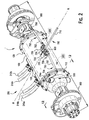
- the hydraulic drive system 1 is symmetrical about an axis A-A shown in Figure 2 .
- the following description of the hydraulic drive system 1 will reference figures depicting a first half of the hydraulic drive system 1, on one side of the symmetrical axis A-A. Components of an opposite second half of the hydraulic drive system 1 will be described similarly to those on the first half, but are not shown in the figures for the sake of brevity. The components of the symmetrical second half of the hydraulic drive system 1, however, are identical to those depicted in the figures.
- the body housing 100 is shown in Figure 2 .
- the body housing 100 is a hollow cylindrical member having a first flange 110 at a first end and a second flange 120 at second end positioned opposite the first end.
- the body housing 100 also has a plurality of fluid line ports 130 disposed on and extending through a side of the body housing 100.
- the fluid line assembly 200 includes a plurality of exterior lines 210, 212, a plurality of wall connectors 214, 216, a plurality of interior lines 220, 222, 230, 232, and a plurality of interior couplings 240, 242, 250, 252.
- the plurality of exterior lines 210, 212 and plurality of interior lines 220, 222, 230, 232 may be any type of hydraulic fluid line known to those with ordinary skill in the art.
- the fluid line assembly 200 of one half of the hydraulic drive system 1 are shown in Figures 2-4 .
- the exterior lines 210 include two pairs of fluid lines 210a and 210b, for intake and outlet of fluid. While a total of four exterior lines 210, in an alternative embodiment, the exterior lines 210 may be replaced by a single pair of fluid lines 210a and 210b.
- a plurality of first wall connectors 214 are connected at a first end to the plurality of first exterior lines 210 and connected at an opposite second end to a first interior line 220 and a second interior line 222.
- the first interior line 220 is connected to a first interior coupling 240 at an end opposite the first wall connector 214
- the second interior line 222 is connected to a second interior coupling 242 at an end opposite the first wall connector 214.
- a plurality of second exterior lines 212 includes two fluid lines 212a and 212b.
- the plurality of second exterior lines 212 may be replaced by a single exterior line 212.
- a plurality of second wall connectors 216 are connected at a first end to the plurality of second exterior lines 212 and are connected at an opposite second end to a third interior line 230 and a fourth interior line 232.
- one second wall connector 216 connects at a first end to the second exterior line 210 and is connected at an opposite second end to the third interior line 230 and the fourth interior line 232.
- the third interior line 230 is connected to a third interior coupling 250 at an end opposite the second wall connector 216
- the fourth interior line 232 is connected to a fourth interior coupling 252 at an end opposite the second wall connector 216.
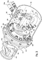
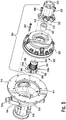
- the first motor assembly 300 is shown in Figures 3-5 . As shown in Figure 5 , the first motor assembly 300 includes a first motor 310, a first motor adaptor 320, a first planetary gear drive 330, and a first motor actuator 340.
- the first motor 310 is a hydraulic motor having a first motor shaft 316 operated by the hydraulic motor.
- the first motor 310 also has a plurality of first motor couplings 312, 314.
- the first motor adaptor 320 in the shown embodiment, is a hollow cylindrical member.
- the first planetary gear drive 330 is a type of planetary gear known to those with ordinary skill in the art, and has a first planetary mating spline 332 extending into a side of the first planetary gear drive 330.
- the first motor actuator 340 has a first motor actuator mating spline 342 disposed on a first end, a plurality of first motor actuator teeth 346 disposed on an opposite second end, and a plurality of first motor actuator ridges 344 disposed between the first end and the second end.
- the first motor actuator mating spline 342 in the shown embodiment, extends along a longitudinal direction of the first motor actuator 340.
- the plurality of first motor actuator ridges 344 protrude circumferentially from the first motor actuator 340.
- the plurality of first motor actuator teeth 346 protrude from the first motor actuator 340 in the longitudinal direction of the first motor actuator 340.
- the second motor assembly 400 includes a second motor 410, a second motor adaptor 420, a second planetary gear drive 430, and a second motor actuator 440.
- the second motor 410 is a hydraulic motor having a second motor shaft 416 operated by the hydraulic motor.
- the second motor 410 also has a plurality of second motor couplings 412, 414.
- the second motor adaptor 420 is a hollow cylindrical member.
- the second planetary gear drive 430 is a type of planetary gear known to those with ordinary skill in the art, and has a second planetary mating spline 432 extending into a side of the second planetary gear drive 430.
- the second motor actuator 440 has a second motor actuator mating spline 442 disposed on a first end, a plurality of second motor actuator teeth 446 disposed on an opposite second end, and a plurality of second motor actuator ridges 444 disposed between the first end and the second end.
- the second motor actuator mating spline 442 extends along a longitudinal direction of the second motor actuator 440.
- the plurality of second motor actuator ridges 444 protrude circumferentially from the second motor actuator 440.
- the plurality of second motor actuator teeth 446 protrude from the second motor actuator 440 in the longitudinal direction of the second motor actuator 440.
- the first rotor assembly 500 is shown in Figures 2 and 7-9 .
- the first rotor assembly 500 includes a first bell housing 510, a first rotor 530, a first brake 540, a first hub assembly 550, a first drive shaft 570, and a first rotor actuator assembly 580.
- the first bell housing 510 is a bell-shaped member defining a first bell housing receiving space 511 and having a first bell housing flange 512 along a first end thereof.
- a first shaft receiving passageway 514 extends through the first bell housing 510 in a direction orthogonal to an axis B-B extending through the first bell housing receiving space 511. The first shaft receiving passageway 514 is positioned toward a side, off-center on the first bell housing 510.
- a tubular first caster housing 516 extends from the first bell housing 510.
- a first frame support 518 is disposed around the first caster housing 516, forming flat surfaces on a top and a bottom of the first caster housing 516.
- a first brake mount 520 is disposed on an end of the first caster housing 516 opposite the first bell housing 510, and extends away from the first caster housing 516.
- the first rotor 530 is shown in Figure 7 .
- the first rotor 530 may be any type of brake rotor known to those with ordinary skill in the art.
- the first brake 540 is shown in Figure 7 and includes a first brake caliper 542 and a plurality of first brake pads 544 disposed within the first brake caliper 542.
- the first brake caliper 542 and the plurality of first brake pads 544 may be any type of brake caliper and brake pads known to those with ordinary skill in the art.
- the first hub assembly 550 is shown in Figures 7 and 8 .
- the first hub assembly 550 includes a first hub housing 552, a first spindle 554, a first inner hub bearing 556, a first outer hub bearing 558, a first hub ring 560, and a first hub retainer 562.
- the first hub housing 552 as shown in Figure 8 , has a circular first hub housing base 552a and a hollow, cylindrical first hub housing body 552 extending from a side of the first hub housing base 552a.
- the first spindle 554 is a substantially tubular member having a first spindle end 554a at a first end and a first spindle securing end 554e at an opposite second end.
- the first spindle securing end 554e may have an exterior thread, as in the shown embodiment.
- the first spindle 554 also has a first spindle groove 554b, a first spindle ridge 554c, and a first outer spindle surface 554d disposed between the first end and the second end.
- the first spindle groove 554b is a groove extending circumferentially around the first spindle 554 adjacent the first end.
- the first spindle ridge 554c protrudes circumferentially around the first spindle 554 and is disposed between the first spindle groove 554b and the first spindle securing end 554e.
- the first outer spindle surface 554d is a flat surface formed orthogonal to a longitudinal direction of the first spindle 554 and extending circumferentially around the first spindle 554.
- the first outer spindle surface 554d is disposed between the first spindle ridge 554c and the first spindle securing end 554e.
- the first inner hub bearing 556 and the first outer hub bearing 558 may be any form of bearing known to those with ordinary skill in the art.
- the first hub ring 560 is a circular member.
- the first hub retainer 562 may be a threaded nut, or may be any other form of retainer known to those with ordinary skill in the art.
- the first drive shaft 570 is shown in Figure 7 .
- the first drive shaft 570 has a first drive shaft flange 572 disposed on a first end and a first drive shaft spline 576 disposed on an opposite second end.
- a first drive shaft body 574 is a cylindrical member extending between the first drive shaft flange 572 and the first drive shaft spline 576.
- the first rotor actuator assembly 580 is shown in Figure 9 .
- the first rotor actuator assembly 580 has a first rotor actuator 582, a plurality of first rotor actuator bearings 590, and a first rotor actuator snap ring 592.
- the first rotor actuator 582 has a plurality of first rotor actuator teeth 584 disposed on a first end thereof, a first rotor actuator mating end 586 at an opposite second end thereof, and a first rotor actuator spline 588 disposed along an interior of the first rotor actuator 582.
- the plurality of first rotor actuator teeth 584 protrude from the first rotor actuator 582 in a longitudinal direction of the first rotor actuator 582.
- the first rotor actuator spline 588 extends along the longitudinal direction of the first rotor actuator 582.
- the first rotor actuator mating end 586 may have an exterior thread, as in the shown embodiment.
- the plurality of first rotor actuator bearings 590 may be any type of bearings known to those with ordinary skill in the art.
- the first actuator snap ring 592 may be any type of snap ring known to those with ordinary skill in the art.
- the second rotor assembly 600 includes a second bell housing 610, a second rotor 630, a second brake 640, a second hub assembly 650, a second drive shaft 670, and a second rotor actuator assembly 680.
- the second bell housing 610 is a bell-shaped member defining a second bell housing receiving space 611 and having a second bell housing flange 612 at a first end.
- a second shaft receiving passageway 614 extends through the second bell housing 610 in a direction orthogonal to an axis B-B extending through the second bell housing receiving space 611. The second shaft receiving passageway 614 is positioned toward a side, off-center on the second bell housing 610.
- a tubular second caster housing 616 extends from the second bell housing 610.
- a second frame support 618 is disposed around the second caster housing 616, forming flat surfaces on a top and a bottom of the second caster housing 616.
- a second brake mount 620 is disposed on an end of the second caster housing 616 opposite the second bell housing 610, and extends away from the second caster housing 616.
- the second rotor 630 may be any type of brake rotor known to those with ordinary skill in the art.
- the second brake 640 includes a second brake caliper 642 and a plurality of second brake pads 644 disposed within the second brake caliper 642.
- the second brake caliper 642 and the plurality of second brake pads 644 may be any type of brake caliper and brake pads known to those with ordinary skill in the art.
- the second hub assembly 650 includes a second hub housing 652, a second spindle 654, a second inner hub bearing 666, a second outer hub bearing 658, a second hub ring 660, and a second hub retainer 662.
- the second hub housing 652 has a circular second hub housing base 652a and a hollow, cylindrical second hub housing body 652 extending from a side of the second hub housing base 652a.
- the second spindle 654 is a substantially tubular member having a second spindle end 654a at a first end and a second spindle securing end 654e at an opposite second end.
- the second spindle securing end 654e may have an exterior thread.
- the second spindle 654 also has a second spindle groove 654b, a second spindle ridge 654c, and a second outer spindle surface 654d disposed between the first end and the second end.
- the second spindle groove 654b is a groove extending circumferentially around the second spindle 654 adjacent the first end.
- the second spindle ridge 654c protrudes circumferentially around the second spindle 654 and is disposed between the second spindle groove 654b and the second spindle securing end 654e.
- the second outer spindle surface 654d is a flat surface formed orthogonal to a longitudinal direction of the second spindle 654 and extending circumferentially around the second spindle 654.
- the second outer spindle surface 654d is disposed between the second spindle ridge 654c and the second spindle securing end 654e.
- the second inner hub bearing 666 and the second outer hub bearing 658 may be any form of bearing known to those with ordinary skill in the art.
- the second hub ring 660 is a circular member.
- the second hub retainer 662 may be a threaded nut, or may be any other form of retainer known to those with ordinary skill in the art.
- the second drive shaft 670 has a second drive shaft flange 672 disposed on a first end and a second drive shaft spline 676 disposed on an opposite second end.
- a second drive shaft body 674 is a cylindrical member extending between the second drive shaft flange 672 and the second drive shaft spline 676.
- the second rotor actuator assembly 680 has a second rotor actuator 682, a plurality of second rotor actuator bearings 690, and a second rotor actuator snap ring 692.
- the second rotor actuator 682 has a plurality of second rotor actuator teeth 684 disposed on a first end, a second rotor actuator mating end 686 at an opposite second end, and a second rotor actuator spline 688 disposed along an interior of the second rotor actuator 682.
- the plurality of second rotor actuator teeth 684 protrude from the second rotor actuator 682 in a longitudinal direction of the second rotor actuator 682.
- the second rotor actuator spline 688 extends along the longitudinal direction of the second rotor actuator 682.
- the second rotor actuator mating end 686 may have an exterior thread.
- the plurality of second rotor actuator bearings 690 may be any type of bearings known to those with ordinary skill in the art.
- the second actuator snap ring 692 may be any type of snap ring known to those with ordinary skill in the art.
- the engagement assembly 700 is shown in Figures 2 , 6 , and 10 .
- the engagement assembly 700 includes a main shaft 710, a pivot coupling 720, a first lever assembly 730, and a second lever assembly 760.
- the main shaft 710 is an elongated cylindrical member.
- the pivot coupling 720 has a first pivot arm 722, a second pivot arm 724, and a plurality of pivot bases 726.
- the first pivot arm 722 and the second pivot arm 724 are L-shaped members, and the plurality of pivot bases 726 are formed as tabs.
- the first lever assembly 730 is shown in Figures 2 , 6 , and 10 .
- the first lever assembly 730 has a first pivot rod 732, a first engagement lever 734, a first lever seal 736, a first lever upper snap ring 738, a first lever upper bearing 740, a first engagement shaft 742, a first lever lower bearing 744, a first lever lower snap ring 746, and a first actuator pivot assembly 750.
- the first pivot rod 732 as shown in Figure 2 , is an elongated cylindrical member.
- the first engagement lever 734 has a first engagement lever protrusion 734a at an end.
- the first engagement lever protrusion 734a is a tubular member extending from the first engagement lever 734, and has a first engagement lever spline 734b disposed along an interior.
- the first lever seal 736 may be a circular rubber seal or any other type of seal known to those with ordinary skill in the art.
- the first lever upper snap ring 738 and the first lever lower snap ring 746 may be any type of snap ring known to those with ordinary skill in the art.
- the first lever upper bearing 740 and the first lever lower bearing 744 may be any type of bearing known to those with ordinary skill in the art.
- the first engagement shaft 742 is a tubular member having a first engagement shaft spline 742a at a first end and a first engagement shaft grommet 742d at an opposite second end.
- the first engagement shaft spline 742a extends along a longitudinal direction of the first engagement shaft 742.
- the first engagement shaft grommet 742d protrudes circumferentially around the first engagement shaft 742.
- the first engagement shaft 742 also has a first engagement shaft upper surface 742b and a first engagement shaft lower surface 742c disposed between the first end and the second end.
- the first engagement shaft upper surface 742b extends circumferentially around the first engagement shaft 742 and perpendicularly to the first engagement shaft 742 adjacent the first end.
- the first engagement shaft lower surface 742c extends circumferentially around the first engagement shaft 742 and perpendicularly to the first engagement shaft 742, and is disposed adjacent the first engagement shaft grommet 742d.
- the first engagement shaft 742 also has a plurality of first engagement shaft keyways 742e formed as indentations extending into the first engagement shaft 742 between the first engagement shaft upper surface 742b and the first engagement shaft lower surface 742c.
- the first actuator pivot assembly 750 is shown in Figure 6 and 10 .
- the first actuator pivot assembly 750 includes a first yoke 752, a plurality of first yoke keys 754, a first upper actuator collar 756, and a first lower actuator collar 758.
- the first yoke 752 is a U-shaped member having a pair of first yoke arms 752a extending in parallel from opposite ends of a first yoke body 752b.
- the plurality of first yoke keys 754 are disposed within the first yoke body 752b.
- the first upper actuator collar 756 and the first lower actuator collar 758, shown in Figure 6 are U-shaped members.
- the first upper actuator collar 756 has a cylindrical first upper actuator collar protrusion 756a extending from an approximate center of the first upper actuator collar 756.
- the first lower actuator collar 758 has a cylindrical first lower actuator collar protrusion 758a extending from an approximate center of the first lower actuator collar 758.
- the second lever assembly 760 has a second pivot rod 762, a second engagement lever 764, a second lever seal 766, a second lever upper snap ring 768, a second lever upper bearing 770, a second engagement shaft 772, a second lever lower bearing 774, a second lever lower snap ring 776, and a second actuator pivot assembly 780.
- the second pivot rod 762 is an elongated cylindrical member.
- the second engagement lever 764 has a second engagement lever protrusion 764a at an end.
- the second engagement lever protrusion 764a is a tubular member extending from the second engagement lever 764, and has a second engagement lever spline 764b disposed along an interior.
- the second lever seal 766 may be a circular rubber seal or any other type of seal known to those with ordinary skill in the art.
- the second lever upper snap ring 768 and the second lever lower snap ring 776 may be any type of snap ring known to those with ordinary skill in the art.
- the second lever upper bearing 770 and the second lever lower bearing 774 may be any type of bearing known to those with ordinary skill in the art.
- the second engagement shaft 772 is a tubular member having a second engagement shaft spline 772a at a first end and a second engagement shaft grommet 772d at an opposite second end.
- the second engagement shaft spline 772a extends along a longitudinal direction of the second engagement shaft 772.
- the second engagement shaft grommet 772d protrudes circumferentially around the second engagement shaft 772.
- the second engagement shaft 772 also has a second engagement shaft upper surface 772b and a second engagement shaft lower surface 772c disposed between the first end and the second end.
- the second engagement shaft upper surface 772b extend circumferentially around the second engagement shaft 772 and perpendicularly to the second engagement shaft 772 adjacent the first end.
- the second engagement shaft lower surface 772c extends circumferentially around the second engagement shaft 772 and perpendicularly to the second engagement shaft 772, and is disposed adjacent the second engagement shaft grommet 772d.
- the second engagement shaft 772 also has a plurality of second engagement shaft keyways 772e formed as indentations extending into the second engagement shaft 772 between the second engagement shaft upper surface 772b and the second engagement shaft lower surface 772c.
- the second actuator pivot assembly 780 includes a second yoke 782, a plurality of second yoke keys 784, a second upper actuator collar 786, and a second lower actuator collar 788.
- the second yoke 782 is a U-shaped member having a pair of second yoke arms 782a extending in parallel from opposite ends of a second yoke body 782b.
- the plurality of second yoke keys 784 are disposed within the second yoke body 782b.
- the second upper actuator collar 786 and the second lower actuator collar 788 are U-shaped members.
- the second upper actuator collar 786 has a cylindrical second upper actuator collar protrusion 786a extending from an approximate center of the second upper actuator collar 786.
- the second lower actuator collar 788 has a cylindrical second lower actuator collar protrusion 788a extending from an approximate center of the second lower actuator collar 788.
- the plurality of first exterior lines 210 extend from outside the body housing 100 to the plurality of fluid line ports 130.
- the plurality of first wall connectors 214 are positioned in the plurality of fluid line ports 130 and connect the plurality of first exterior lines 210 with the first interior line 220 and the second interior line 222 positioned inside the body housing 100.
- the first motor assembly 300 is positioned inside the body housing 100.
- the first interior coupling 240 connects the first interior line 220 to the first motor coupling 314, and the second interior coupling 242 connects the second interior line 222 to the first motor coupling 312.
- a plurality of fasteners 800 attach the first motor 310 to a first side of the first planetary gear drive 330.
- the first motor shaft 316 extends into the first planetary gear drive 330, and is surrounded by the first motor adaptor 320, which permits the first motor 310 to engage with and operate the first planetary gear drive 330.
- the first motor actuator 340 is disposed in an opposite second side of the first planetary gear drive 330, with the first motor actuator mating spline 342 mating with the first planetary mating spline 332. Due to the mating of the first motor actuator mating spline 342 and the first planetary mating spline 332, the first motor actuator 340 is movable with respect to the first planetary gear drive 330 in a direction of the longitudinal axis of the first motor actuator 340.
- a plurality of fasteners 800 attach the second side of the first planetary gear drive 330 to the first bell housing flange 512.
- the first motor actuator 340 and a portion of the first planetary gear drive 330 are disposed in the first bell housing receiving space 511.
- the body housing 100 is also attached to the first bell housing flange 512 by a plurality of fasteners 800, with the body housing 100 positioned around the first planetary gear drive 330 and containing the first motor assembly 300.
- the first rotor actuator 582 is disposed in the first bell housing receiving space 511, as shown in Figure 9 and 11 , with the first rotor actuator teeth 584 facing the first motor actuator teeth 346.
- the plurality of first rotor actuator bearings 590 are secured to the first rotor actuator 582 by the first rotor actuator snap ring 592.
- the first rotor actuator 582 is secured to the first bell housing 510 within the first bell housing receiving space 511 by the plurality of first rotor actuator bearings 590, and the first rotor actuator 582 is rotatable within the plurality of first rotor actuator bearings 590 and with respect to the first bell housing 510.
- the first hub assembly 550 is assembled with the first rotor assembly 500 as shown in Figures 8 and 11 .
- the first spindle end 554a and the first spindle groove 554b are disposed within the first caster housing 516, with the first spindle ridge 554c abutting an end of the first caster housing 516.
- a plurality of fasteners 800 extend through the first caster housing 516, abutting the first caster housing 516 and disposed within each first spindle groove 554b to secure the first spindle 554 with respect to the first caster housing 516.
- the first outer spindle surface 554d and the first spindle securing end 554e are disposed outside of the first caster housing 516.
- the first inner hub bearing 556 is positioned around the first spindle 554 and abuts the first outer spindle surface 554d.
- the first hub housing base 552a is disposed around and abuts the first inner hub bearing 556.
- the first outer hub bearing 558 is positioned around the first spindle 554 adjacent the second end and is disposed between the first hub housing body 552b and the first spindle 554.
- the first outer hub bearing 558 is secured to the first spindle 554 by the first hub ring 560 and the first hub retainer 562 mating with the first spindle securing end 554e. Due to both the first inner hub bearing 556 and the first outer hub bearing 558 being disposed between the first hub housing 552 and the first spindle 554, the first hub housing 552 is rotatable with respect to the first spindle 554.
- the first rotor 530 is attached to the first hub housing base 552a by a plurality of fasteners 800.
- the first rotor 530 is thus also rotatable with respect to the first spindle 554.
- the first brake 540 is disposed on the first rotor 530 with the first brake pads 554 adjacent the first rotor 530 on each side of the first rotor 530 and the first brake caliper 542 disposed around the first brake pads 544.
- a side of the first brake caliper 542 is attached at each end to the first brake mount 520.
- the first brake 540 is secured to the first caster housing 516 and the first rotor 530 can rotate within the first brake 540.
- the first drive shaft flange 572 is attached to the first hub housing body 552b by a plurality of fasteners 800, as shown in Figures 7 and 11 , and the first drive shaft body 574 extends through the first spindle 554.
- the first drive shaft spline 576 mates with the first rotor actuator spline 588 such that the first drive shaft 570, the first hub housing 552, and the first rotor 530 rotate with the first rotor actuator 582.
- the main shaft 710 is positioned outside of the body housing 100 and attached along a first end to a first end of the first pivot arm 722 and a first end of the second pivot arm 724.
- the plurality of pivot bases 726 are attached to an exterior of the body housing 100, and a center of each of the first pivot arm 722 and the second pivot arm 724 is pivotably attached to one of the plurality of pivot bases 726 by a fastener 800.
- first pivot arm 722 An opposite second end of the first pivot arm 722, as shown in Figure 2 , is pivotably attached to the first pivot rod 732 which extends outside of the body housing 100 from the first pivot arm 722 to the first engagement lever 734.
- the first pivot rod 732 is attached to an end of the first engagement lever 734 opposite the first engagement lever protrusion 734a.
- the first engagement lever 734 is disposed on the first bell housing 510 with the first engagement lever protrusion 734a disposed over the first shaft receiving passageway 514.
- the first engagement shaft 742 extends through the first shaft receiving passageway 514.
- the first engagement shaft spline 742a engages with the first engagement lever spline 734b such that motion of the first engagement lever 734 imparts motion to the first engagement shaft 742.
- the first lever seal 736 is disposed within the first lever upper snap ring 738 and positioned around the first engagement shaft 742 outside the first bell housing 510.
- the first lever upper bearing 740 is disposed around the first engagement shaft 742 and seated within the first shaft receiving passageway 514.
- the first lever upper bearing 740 also abuts the first engagement shaft upper surface 742b.
- the second end of the first engagement shaft 742 extends out of the first shaft receiving passageway 514.
- the first lever lower bearing 744 is disposed around the first engagement shaft 742 and is held on the first engagement shaft 742 by the first engagement shaft grommet 742d.
- the first lever lower bearing 744 is seated in the first shaft receiving passageway 514 and also abuts the first engagement shaft lower surface 742c. Due to the first lever upper bearing 740 and the first lever lower bearing 744, the first engagement shaft 742 is rotatable with respect to the first bell housing 510.
- the first lever lower snap ring 746 is disposed in the end of the first shaft receiving passageway 514 adjacent the second end of the first engagement shaft 742.
- the first actuator pivot assembly 750 is attached to the first engagement shaft 742 within the first bell housing receiving space 511.
- the first yoke body 752b is disposed around the first engagement shaft 742 and secured by a plurality of fasteners 800.
- the plurality of first yoke keys 754 each engage one of the plurality of first engagement shaft keyways 742e, fixing the first yoke 752 with respect to the first engagement shaft 742.
- the first upper actuator collar protrusion 756a is rotatably connected to an end of one of the pair of first yoke arms 752a and the first lower actuator collar protrusion 758a is rotatably connected to an end of the other of the pair of first yoke arms 752a.
- the first upper actuator collar 756 and the first lower actuator collar 758 each engage the plurality of first motor actuator ridges 344 on a side of the first motor actuator 340, and a plurality of fasteners 800 connect the first upper actuator collar 756 to the first lower actuator collar 758, fixing the first motor actuator 340 between the first upper actuator collar 756 and the first lower actuator collar 758.
- the first motor actuator 340 is thus disposed within the first planetary gear drive 330 and also attached to the first actuator pivot assembly 750.
- the plurality of second exterior lines 212 extend from outside the body housing 100 to the plurality of fluid line ports 130.
- the plurality of second wall connectors 216 are positioned in the plurality of fluid line ports 130 and connect the plurality of second exterior lines 212 with the third interior line 230 and the fourth interior line 262 positioned inside the body housing 100.
- the second motor assembly 400 is positioned inside the body housing 100.
- the third interior coupling 250 connects the third interior line 230 to the second motor coupling 414, and the fourth interior coupling 262 connects the fourth interior line 242 to the second motor coupling 412.
- a plurality of fasteners 800 attach the second motor 410 to a first side of the second planetary gear drive 430.
- the second motor shaft 416 extends into the second planetary gear drive 430, and is surrounded by the second motor adaptor 420, which permits the second motor 410 to engage with and operate the second planetary gear drive 430.
- the second motor actuator 440 is disposed in an opposite second side of the second planetary gear drive 430, with the second motor actuator mating spline 442 mating with the second planetary mating spline 432. Due to the mating of the second motor actuator mating spline 442 and the second planetary mating spline 432, the second motor actuator 440 is movable with respect to the second planetary gear drive 430 in a direction of the longitudinal axis of the second motor actuator 440.
- a plurality of fasteners 800 attach the second side of the second planetary gear drive 430 to the second bell housing flange 612.
- the second motor actuator 440 and a portion of the second planetary gear drive 430 are disposed in the second bell housing receiving space 611.
- the body housing 100 also attached to the second bell housing flange 612 by a plurality of fasteners 800, with the body housing 100 positioned around the second planetary gear drive 430 and containing the second motor assembly 400.
- the second rotor actuator 682 is disposed in the second bell housing receiving space 611, with the second rotor actuator teeth 684 facing the second motor actuator teeth 446.
- the plurality of second rotor actuator bearings 690 are secured to the second rotor actuator 682 by the second rotor actuator snap ring 692.
- the second rotor actuator 682 is secured to the second bell housing 610 within the second bell housing receiving space 611 by the plurality of second rotor actuator bearings 690, and the second rotor actuator 682 is rotatable within the plurality of second rotor actuator bearings 690 and with respect to the second bell housing 610.
- the second hub assembly 650 is assembled with the second rotor assembly 600.
- the second spindle end 654a and the second spindle groove 654b are disposed within the second caster housing 616, with the second spindle ridge 654c abutting an end of the second caster housing 616.
- a plurality of fasteners 800 extend through the second caster housing 616, abutting the second caster housing 616 and disposed within each second spindle groove 654b to secure the second spindle 654 with respect to the second caster housing 616.
- the second outer spindle surface 654d and the second spindle securing end 654e are disposed outside of the second caster housing 616.
- the second inner hub bearing 656 is positioned around the second spindle 654 and abuts the second outer spindle surface 654d.
- the second hub housing base 652a is disposed around and abuts the second inner hub bearing 656.
- the second outer hub bearing 658 is positioned around the second spindle 654 adjacent the second end and is disposed between the second hub housing body 652b and the second spindle 654.
- the second outer hub bearing 658 is secured to the second spindle 654 by the second hub ring 660 and the second hub retainer 662 mating with the second spindle securing end 654e. Due to both the second inner hub bearing 656 and the second outer hub bearing 658 being disposed between the second hub housing 652 and the second spindle 654, the second hub housing 652 is rotatable with respect to the second spindle 654.
- the second rotor 630 is attached to the second hub housing base 652a by a plurality of fasteners 800.
- the second rotor 630 is thus also rotatable with respect to the second spindle 654.
- the second brake 640 is disposed on the second rotor 630 with the second brake pads 654 adjacent the second rotor 630 on each side of the second rotor 630 and the second brake caliper 642 disposed around the second brake pads 644.
- a side of the second brake caliper 642 is attached at each end to the second brake mount 620.
- the second brake 640 is secured to the second caster housing 616 and the second rotor 630 can rotate within the second brake 640.
- the second drive shaft flange 672 is attached to the second hub housing body 652b by a plurality of fasteners 800, and the second drive shaft body 674 extends through the second spindle 654.
- the second drive shaft spline 676 mates with the second rotor actuator spline 688 such that the second drive shaft 670, the second hub housing 652, and the second rotor 630 rotate with the second rotor actuator 682.
- An opposite second end of the second pivot arm 724 is pivotably attached to the second pivot rod 762 which extends outside of the body housing 100 from the second pivot arm 724 to the second engagement lever 764.
- the second pivot rod 762 is attached to an end of the second engagement lever 764 opposite the second engagement lever protrusion 764a.
- the second engagement lever 764 is disposed on the second bell housing 610 with the second engagement lever protrusion 764a disposed over the second shaft receiving passageway 614.
- the second engagement shaft 772 extends through the second shaft receiving passageway 614.
- the second engagement shaft spline 772a engages with the second engagement lever spline 764b such that motion of the second engagement lever 764 imparts motion to the second engagement shaft 772.
- the second lever seal 766 is disposed within the second lever upper snap ring 768 and positioned around the second engagement shaft 772 outside the second bell housing 610.
- the second lever upper bearing 770 is disposed around the second engagement shaft 772 and seated within the second shaft receiving passageway 614.
- the second lever upper bearing 770 also abuts the second engagement shaft upper surface 772b.
- the second end of the second engagement shaft 772 extends out of the second shaft receiving passageway 614.
- the second lever lower bearing 774 is disposed around the second engagement shaft 772 and is held on the second engagement shaft 772 by the second engagement shaft grommet 772d.
- the second lever lower bearing 774 is seated in the second shaft receiving passageway 614 and also abuts the second engagement shaft lower surface 772c. Due to the second lever upper bearing 770 and the second lever lower bearing 774, the second engagement shaft 772 is rotatable with respect to the second bell housing 610.
- the second lever lower snap ring 776 is disposed in the end of the second shaft receiving passageway 614 adjacent the second end of the second engagement shaft 772.
- the second actuator pivot assembly 780 is attached to the second engagement shaft 772 within the second bell housing receiving space 611.
- the second yoke body 782b is disposed around the second engagement shaft 772 and secured by a plurality of fasteners 800.
- the plurality of second yoke keys 784 each engage one of the plurality of second engagement shaft keyways 772e, fixing the second yoke 782 with respect to the second engagement shaft 772.
- the second upper actuator collar protrusion 786a is rotatably connected to an end of one of the pair of second yoke arms 782a and the second lower actuator collar protrusion 788a is rotatably connected to an end of the other of the pair of second yoke arms 782a.
- the second upper actuator collar 786 and the second lower actuator collar 788 each engage the plurality of second motor actuator ridges 444 on a side of the second motor actuator 440, and a plurality of fasteners 800 connect the second upper actuator collar 786 to the second lower actuator collar 788, fixing the second motor actuator 440 between the second upper actuator collar 786 and the second lower actuator collar 788.
- the second motor actuator 440 is thus disposed within the second planetary gear drive 430 and also attached to the second actuator pivot assembly 780.
- the frame 910 is a rigid structure formed from a plurality of beams 914.
- the frame 910 has a hitch 912 disposed at a first end.
- the hitch 912 includes a connector, for example, a ball mount, for connecting the frame 910 with a towing device (not shown).
- the pair of steerable wheels 950 are both positioned under and pivotably attached to the frame 910 adjacent the first end.
- the hydraulic drive system 1 is attached to an underside of the frame 910 adjacent an opposite second end of the frame 910.
- the hydraulic drive system 1 extends orthogonally with respect to a longitudinal axis of the frame 910.
- Each of the pair of drive wheels 940 is attached to one of the first rotor 530 and the second rotor 630.
- the pair of drive wheels 940 and the pair of steerable wheels 950 together support the frame 910 and components attached to the frame 910.
- the fluid supply system 920 supplies hydraulic fluid to the hydraulic drive system 1.
- the fluid supply system 920 has a pump 922 and a fluid reservoir 924 each attached to the frame 910.
- the fluid reservoir 924 stores hydraulic fluid.
- the pump 922 is connected to the plurality of first exterior lines 210 and the plurality of second exterior lines 212 and pumps hydraulic fluid from the fluid reservoir 924 through the fluid line assembly 200.
- the pump 922 is capable of pumping hydraulic fluid through the fluid line assembly 200 in either a first direction or an opposite second direction.
- the engagement mechanism 930 is attached to an underside of the frame 910.
- the engagement mechanism 930 is connected to the hitch 912 at a first end and the main shaft 710 at an opposite second end.
- the engagement mechanism 930 moves the main shaft 710 in a longitudinal direction of the main shaft 710 based on whether the hitch 912 is attached to the towing device.
- the hydraulic drive system 1 is used to drive the pair of drive wheels 940 to more precisely locate the trailer 900 when the trailer 900 is not being towed.
- the plurality of first motor actuator teeth 346 are matable with the plurality of first rotor actuator teeth 584.
- the plurality of second motor actuator teeth 446 are matable with the plurality of second rotor actuator teeth 684.
- the engagement assembly 700 moves the first motor actuator 340 with respect to the first rotor actuator 582 between an engagement position in which the first motor actuator 340 mates with and engages the first rotor actuator 582 and a disengagement position in which the first motor actuator 340 and the first rotor actuator 582 are separated.
- the engagement assembly 700 likewise moves the second motor actuator 440 with respect to the second rotor actuator 682 between the engagement position in which the second motor actuator 440 mates with and engages the second rotor actuator 682 and the disengagement position in which the second motor actuator 440 and the second rotor actuator 682 are separated.
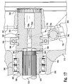
- the engagement position of the hydraulic drive system 1 is shown in Figures 14 and 17 . As shown in Figures 1 and 14 , when the hitch 912 is not attached to the towing device, the engagement mechanism 930 does not affect the main shaft 710, and the main shaft 710 is positioned closer to the body housing 100.
- the first pivot rod 732 is positioned closer to the main shaft 710, pulling the first engagement lever 734 toward the housing body 100.
- the first yoke 752 turns with the first engagement shaft 742 and moves the first motor actuator 340 toward the first rotor actuator 582 in a longitudinal direction of the first motor actuator 340.
- the first motor actuator 340 is moved until the plurality of first motor actuator teeth 346 engage with the plurality of first rotor actuator teeth 584.
- a portion of the first motor actuator 340 remains within the first planetary gear drive 330 as the first motor actuator mating spline 342 slides along the first planetary mating spline 332 during motion of the first motor actuator 340.
- the hydraulic drive system 1 only provides motive power to the pair of drive wheels 940 in the engagement position in which the plurality of first motor actuator teeth 346 are engaged with the plurality of first rotor actuator teeth 584. In the engagement position, rotation of the first motor actuator 340 imparts rotation to the first rotor actuator 582.
- the pump 922 pumps hydraulic fluid from the fluid reservoir 924 through the plurality of first exterior lines 210 and through each of the first interior line 220 and the second interior line 222, as shown in Figures 3 and 14 . Depending on the direction of fluid flow created by the pump 922, one of the first interior line 220 and the second interior line 222 is an input line, and the other of the first interior line 220 and the second interior line 222 is an output line.
- the first interior line 220 and the second interior line 222 transmit hydraulic fluid to operate the first motor 310, which operates the first planetary gear drive 330.
- Rotation of the first planetary gear drive 330 rotates the first motor actuator 340 via the interaction of the first planetary mating spline 332 and the first motor actuator mating spline 342.
- rotation of the first motor actuator 340 imparts rotation to the first rotor actuator 582.
- rotation of the first rotor actuator 582 rotates the first drive shaft 570 via the interaction of the first rotor actuator spline 588 and the first drive shaft spline 576.
- the first drive shaft 570 is fixed to the first hub housing 552 and the first hub housing 552 is fixed to the first rotor 530, and consequently, rotation of the first drive shaft 570 imparts rotation to the first rotor 530, providing motive power to one of the pair of drive wheels 940. If, for example, the first interior line 220 is the input line, the first motor 310 imparts a rotation that turns the drive wheel 940 in a clockwise direction, and if the first interior line 220 is the output line, the first motor 310 imparts a rotation that turns the drive wheel 940 in a counterclockwise direction.
- a similar engagement occurs on the symmetrical other side of the hydraulic drive system 1.
- the second pivot rod 762 is positioned closer to the main shaft 710, pulling the second engagement lever 764 toward the housing body 100.
- the second yoke 782 turns with the second engagement shaft 772 and moves the second motor actuator 440 toward the second rotor actuator 682 in a longitudinal direction of the second motor actuator 440.
- the second motor actuator 440 is moved until the plurality of second motor actuator teeth 446 engage with the plurality of second rotor actuator teeth 684.
- a portion of the second motor actuator 440 remains within the second planetary gear drive 430 as the second motor actuator mating spline 442 slides along the second planetary mating spline 432 during motion of the second motor actuator 440.
- the hydraulic drive system 1 only provides motive power to the pair of drive wheels 940 in the engagement position in which the plurality of second motor actuator teeth 446 are engaged with the plurality of second rotor actuator teeth 684. In the engagement position, rotation of the second motor actuator 440 imparts rotation to the second rotor actuator 682.
- the pump 922 pumps hydraulic fluid from the fluid reservoir 924 through the plurality of second exterior lines 220 and through each of the third interior line 230 and the fourth interior line 232. Depending on the direction of fluid flow created by the pump 922, one of the third interior line 230 and the fourth interior line 232 is an input line, and the other of the third interior line 230 and the fourth interior line 232 is an output line.
- the third interior line 230 and the fourth interior line 232 provide hydraulic fluid to operate the second motor 410, which operates the second planetary gear drive 430.
- Rotation of the second planetary gear drive 430 rotates the second motor actuator 440 via the interaction of the second planetary mating spline 432 and the second motor actuator mating spline 442.
- Rotation of the second motor actuator 440 imparts rotation to the second rotor actuator 682, and correspondingly, rotation of the second rotor actuator 682 rotates the second drive shaft 670 via the interaction of the second rotor actuator spline 688 and the second drive shaft spline 676.
- the second drive shaft 670 is fixed to the second hub housing 652 and the second hub housing 652 is fixed to the second rotor 630, and consequently, rotation of the second drive shaft 670 imparts rotation to the second rotor 630, providing motive power to one of the pair of drive wheels 940.
- the second motor 410 imparts a rotation that turns the drive wheel 940 in a clockwise direction
- the second motor 410 imparts a rotation that turns the drive wheel 940 in a counterclockwise direction.
- the engagement assembly 700 automatically moves to the engagement position in which rotation of either the first motor 3 10 or the second motor 410 imparts rotation to the pair of drive wheels 940, allowing the hydraulic drive system 1 to drive the trailer 900.
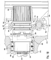
- the disengagement position of the hydraulic drive system 1 is shown in Figures 15 and 18 .
- the engagement mechanism 930 pulls the main shaft 710 in a direction away from the body housing 100 along the longitudinal axis of the main shaft 710.
- the first pivot rod 732 is positioned further from the main shaft 710, pushing the first engagement lever 734 in a direction away from the housing body 100.
- the first yoke 752 turns with the first engagement shaft 742 and moves the first motor actuator 340 away from the first rotor actuator 582 in the longitudinal direction of the first motor actuator 340.
- the first motor actuator 340 is moved until the plurality of first motor actuator teeth 346 disengage from the plurality of first rotor actuator teeth 584. In the disengagement position, the plurality of first motor actuator teeth 346 are separated from and face the plurality of first rotor actuator teeth 584.
- a similar disengagement occurs on the symmetrical other side of the hydraulic drive system 1.
- the second pivot rod 762 is positioned further from the main shaft 710, pushing the second engagement lever 764 in a direction away from the housing body 100.
- the second yoke 782 turns with the second engagement shaft 772 and moves the second motor actuator 440 away from the second rotor actuator 682 in the longitudinal direction of the second motor actuator 440 until the plurality of second motor actuator teeth 446 disengage from the plurality of second rotor actuator teeth 684.
- the plurality of second motor actuator teeth 446 are separated from and face the plurality of second rotor actuator teeth 684.
- the engagement assembly 700 automatically moves to the disengagement position in which rotation of either the first motor 310 or the second motor 410 does not impart rotation to any portion of the first or second rotor assemblies 500, 600.
- the pair of drive wheels 940 thus roll freely without impairment from the first motor 310 or the second motor 410 when the hydraulic drive system 1 is not needed to drive the pair of drive wheels 940.
Landscapes
- Engineering & Computer Science (AREA)
- Mechanical Engineering (AREA)
- Chemical & Material Sciences (AREA)
- Combustion & Propulsion (AREA)
- Transportation (AREA)
- General Engineering & Computer Science (AREA)
- Retarders (AREA)
- Braking Arrangements (AREA)
- Hydraulic Motors (AREA)
- Details And Applications Of Rotary Liquid Pumps (AREA)
Abstract
Description
- The present invention relates to a hydraulic drive system, and more particularly, to a hydraulic drive system powering drive wheels of a self-propelled trailer.
- Hydraulic drive systems providing motive power in various applications, including providing power to drive wheels, are known in the art. In various applications, known hydraulic drive systems, used power drive wheels, have one or more hydraulic motors that continually connected and engaged with each drive wheel.
- Many hydraulic drive system applications do not require the hydraulic motors to always provide the motive power, and consequently, the hydraulic motors are disengaged when not in use to prevent a resistance that slows the drive wheel and decreases the useful life of the hydraulic motor. However, known hydraulic drive systems are difficult to disengage and are disengaged manually. Known hydraulic drive systems thus decrease efficiency by not permitting simple engagement and disengagement, and by not optimally engaging and disengaging drive wheels depending on the required use of the hydraulic motors.
- An object of the invention, among others, is to provide a hydraulic drive system capable of engaging and disengaging drive wheels. Accordingly, a hydraulic drive system according to the invention is provided. The hydraulic drive system includes a body housing, a rotor assembly, a motor assembly, and an engagement assembly. The first rotor assembly is attached to a first side of the body housing, while the first motor assembly is disposed inside the body housing and includes a first motor actuator. The engagement assembly positions the first motor actuator to engage and disengage with the first rotor assembly.
- The invention will now be described by way of example with reference to the accompanying figures, of which:
-
Figure 1 is a perspective view of a trailer and a hydraulic drive system according to the invention; -
Figure 2 is a perspective view of a hydraulic drive system according to the invention; -
Figure 3 is a partial sectional view of the hydraulic drive system ofFigure 2 ; -
Figure 4 is an exploded view of a motor assembly, a rotor assembly, and a body housing of the hydraulic drive system ofFigure 2 ; -
Figure 5 is an exploded view of the motor assembly ofFigure 3 ; -
Figure 6 is an exploded view of a motor actuator of the motor assembly ofFigure 3 ; -
Figure 7 is an exploded view of the rotor assembly ofFigure 4 ; -
Figure 8 is an exploded view of a hub assembly of the rotor assembly ofFigure 4 ; -
Figure 9 is an exploded view of a rotor actuator assembly of the rotor assembly ofFigure 4 ; -
Figure 10 is an exploded view of a lever assembly of the hydraulic drive system ofFigure 1 ; -
Figure 11 is a partial sectional view of the hydraulic drive system ofFigure 1 , showing one half thereof; -
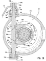
Figure 12 is a sectional view of a lever assembly for the hydraulic drive system ofFigure 10 ; -
Figure 13 is a perspective view of the lever assembly for the hydraulic drive system ofFigure 10 ; -
Figure 14 is top plan view of the hydraulic drive system ofFigure 1 in an engagement position; -
Figure 15 is a top plan view of the hydraulic drive system ofFigure 1 in a disengagement position; -
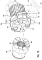
Figure 16 is a perspective view of a rotor actuator and a motor actuator of the hydraulic drive system ofFigure 1 ; -
Figure 17 is a sectional view of the hydraulic drive system ofFigure 1 in the engagement position; and -
Figure 18 is a sectional view of the hydraulic drive system ofFigure 1 in the disengagement position. - The invention is explained in greater detail below with reference to exemplary embodiments of a hydraulic drive system according to the invention. However, this invention may be embodied in many different forms and should not be construed as limited to the embodiments set forth herein; rather, these embodiments are provided so that this disclosure will be thorough and complete and still fully convey the scope of the invention to those skilled in the art.
- With respect to
Figure 1 , a hydraulic drive system 1 according to the invention is shown. In an exemplary embodiment of the invention, the hydraulic drive system 1 according to the invention is shown with aframe 910, afluid supply system 920, anengagement mechanism 930, a pair ofdrive wheels 940, and a pair ofsteerable wheels 950. - With respect to
Figure 2 , the hydraulic drive system 1 according to the invention is shown in greater detail. The hydraulic drive system 1 includes the following major components: abody housing 100, afluid line assembly 200, afirst motor assembly 300, asecond motor assembly 400, afirst rotor assembly 500, asecond rotor assembly 600, and anengagement assembly 700. - A plurality of
fasteners 800 are shown in the figures and described below. It should be known to one skilled in the art that thefastener 800 may be a screw, a nut and bolt, a pin and clip, an adhesive, a weld, or any other type of fastener known to those with ordinary skill in the art. - As shown, the hydraulic drive system 1 is symmetrical about an axis A-A shown in
Figure 2 . The following description of the hydraulic drive system 1 will reference figures depicting a first half of the hydraulic drive system 1, on one side of the symmetrical axis A-A. Components of an opposite second half of the hydraulic drive system 1 will be described similarly to those on the first half, but are not shown in the figures for the sake of brevity. The components of the symmetrical second half of the hydraulic drive system 1, however, are identical to those depicted in the figures. - The
body housing 100 is shown inFigure 2 . In the shown embodiment, thebody housing 100 is a hollow cylindrical member having afirst flange 110 at a first end and asecond flange 120 at second end positioned opposite the first end. Thebody housing 100 also has a plurality offluid line ports 130 disposed on and extending through a side of thebody housing 100. - The
fluid line assembly 200 includes a plurality ofexterior lines 210, 212, a plurality ofwall connectors 214, 216, a plurality ofinterior lines interior couplings exterior lines 210, 212 and plurality ofinterior lines fluid line assembly 200 of one half of the hydraulic drive system 1 are shown inFigures 2-4 . - As shown in
Figure 2 , theexterior lines 210 include two pairs offluid lines exterior lines 210, in an alternative embodiment, theexterior lines 210 may be replaced by a single pair offluid lines - As shown in
Figure 3 , a plurality offirst wall connectors 214 are connected at a first end to the plurality of firstexterior lines 210 and connected at an opposite second end to a firstinterior line 220 and a secondinterior line 222. - As shown in
Figures 3 and4 , the firstinterior line 220 is connected to a firstinterior coupling 240 at an end opposite thefirst wall connector 214, and the secondinterior line 222 is connected to a secondinterior coupling 242 at an end opposite thefirst wall connector 214. - As shown in
Figure 2 , a plurality of second exterior lines 212 includes twofluid lines - A plurality of second wall connectors 216 are connected at a first end to the plurality of second exterior lines 212 and are connected at an opposite second end to a third interior line 230 and a fourth interior line 232. In the alternative embodiment described above, in which the plurality of second exterior lines 212 are replaced by a single exterior line 212, one second wall connector 216 connects at a first end to the second
exterior line 210 and is connected at an opposite second end to the third interior line 230 and the fourth interior line 232. - The third interior line 230 is connected to a third interior coupling 250 at an end opposite the second wall connector 216, and the fourth interior line 232 is connected to a fourth interior coupling 252 at an end opposite the second wall connector 216.
- The
first motor assembly 300 is shown inFigures 3-5 . As shown inFigure 5 , thefirst motor assembly 300 includes afirst motor 310, afirst motor adaptor 320, a firstplanetary gear drive 330, and afirst motor actuator 340. - The
first motor 310, as shown inFigure 5 , is a hydraulic motor having afirst motor shaft 316 operated by the hydraulic motor. Thefirst motor 310 also has a plurality offirst motor couplings first motor adaptor 320, in the shown embodiment, is a hollow cylindrical member. The firstplanetary gear drive 330 is a type of planetary gear known to those with ordinary skill in the art, and has a firstplanetary mating spline 332 extending into a side of the firstplanetary gear drive 330. - As shown in
Figures 5 and6 , thefirst motor actuator 340 has a first motoractuator mating spline 342 disposed on a first end, a plurality of firstmotor actuator teeth 346 disposed on an opposite second end, and a plurality of firstmotor actuator ridges 344 disposed between the first end and the second end. The first motoractuator mating spline 342, in the shown embodiment, extends along a longitudinal direction of thefirst motor actuator 340. The plurality of firstmotor actuator ridges 344 protrude circumferentially from thefirst motor actuator 340. The plurality of firstmotor actuator teeth 346 protrude from thefirst motor actuator 340 in the longitudinal direction of thefirst motor actuator 340. - The
second motor assembly 400 includes a second motor 410, a second motor adaptor 420, a second planetary gear drive 430, and a second motor actuator 440. - The second motor 410 is a hydraulic motor having a second motor shaft 416 operated by the hydraulic motor. The second motor 410 also has a plurality of second motor couplings 412, 414. The second motor adaptor 420 is a hollow cylindrical member. The second planetary gear drive 430 is a type of planetary gear known to those with ordinary skill in the art, and has a second planetary mating spline 432 extending into a side of the second planetary gear drive 430.
- The second motor actuator 440 has a second motor actuator mating spline 442 disposed on a first end, a plurality of second motor actuator teeth 446 disposed on an opposite second end, and a plurality of second motor actuator ridges 444 disposed between the first end and the second end. The second motor actuator mating spline 442 extends along a longitudinal direction of the second motor actuator 440. The plurality of second motor actuator ridges 444 protrude circumferentially from the second motor actuator 440. The plurality of second motor actuator teeth 446 protrude from the second motor actuator 440 in the longitudinal direction of the second motor actuator 440.
- The
first rotor assembly 500 is shown inFigures 2 and7-9 . Thefirst rotor assembly 500 includes afirst bell housing 510, afirst rotor 530, afirst brake 540, afirst hub assembly 550, afirst drive shaft 570, and a firstrotor actuator assembly 580. - The
first bell housing 510, as shown inFigures 7 and9 , is a bell-shaped member defining a first bellhousing receiving space 511 and having a firstbell housing flange 512 along a first end thereof. A firstshaft receiving passageway 514 extends through thefirst bell housing 510 in a direction orthogonal to an axis B-B extending through the first bellhousing receiving space 511. The firstshaft receiving passageway 514 is positioned toward a side, off-center on thefirst bell housing 510. A tubularfirst caster housing 516 extends from thefirst bell housing 510. Afirst frame support 518 is disposed around thefirst caster housing 516, forming flat surfaces on a top and a bottom of thefirst caster housing 516. As shown inFigure 8 , afirst brake mount 520 is disposed on an end of thefirst caster housing 516 opposite thefirst bell housing 510, and extends away from thefirst caster housing 516. - The
first rotor 530 is shown inFigure 7 . Thefirst rotor 530 may be any type of brake rotor known to those with ordinary skill in the art. - The
first brake 540 is shown inFigure 7 and includes afirst brake caliper 542 and a plurality offirst brake pads 544 disposed within thefirst brake caliper 542. Thefirst brake caliper 542 and the plurality offirst brake pads 544 may be any type of brake caliper and brake pads known to those with ordinary skill in the art. - The
first hub assembly 550 is shown inFigures 7 and8 . Thefirst hub assembly 550 includes afirst hub housing 552, afirst spindle 554, a first inner hub bearing 556, a first outer hub bearing 558, afirst hub ring 560, and afirst hub retainer 562. - The
first hub housing 552, as shown inFigure 8 , has a circular firsthub housing base 552a and a hollow, cylindrical firsthub housing body 552 extending from a side of the firsthub housing base 552a. - The
first spindle 554, as shown inFigure 8 , is a substantially tubular member having afirst spindle end 554a at a first end and a firstspindle securing end 554e at an opposite second end. The firstspindle securing end 554e may have an exterior thread, as in the shown embodiment. Thefirst spindle 554 also has afirst spindle groove 554b, afirst spindle ridge 554c, and a firstouter spindle surface 554d disposed between the first end and the second end. Thefirst spindle groove 554b is a groove extending circumferentially around thefirst spindle 554 adjacent the first end. Thefirst spindle ridge 554c protrudes circumferentially around thefirst spindle 554 and is disposed between thefirst spindle groove 554b and the firstspindle securing end 554e. The firstouter spindle surface 554d is a flat surface formed orthogonal to a longitudinal direction of thefirst spindle 554 and extending circumferentially around thefirst spindle 554. The firstouter spindle surface 554d is disposed between thefirst spindle ridge 554c and the firstspindle securing end 554e. - The first inner hub bearing 556 and the first outer hub bearing 558, as shown in
Figure 8 , may be any form of bearing known to those with ordinary skill in the art. Thefirst hub ring 560 is a circular member. Thefirst hub retainer 562 may be a threaded nut, or may be any other form of retainer known to those with ordinary skill in the art. - The
first drive shaft 570 is shown inFigure 7 . Thefirst drive shaft 570 has a firstdrive shaft flange 572 disposed on a first end and a firstdrive shaft spline 576 disposed on an opposite second end. A firstdrive shaft body 574 is a cylindrical member extending between the firstdrive shaft flange 572 and the firstdrive shaft spline 576. - The first
rotor actuator assembly 580 is shown inFigure 9 . The firstrotor actuator assembly 580 has afirst rotor actuator 582, a plurality of firstrotor actuator bearings 590, and a first rotoractuator snap ring 592. Thefirst rotor actuator 582 has a plurality of firstrotor actuator teeth 584 disposed on a first end thereof, a first rotoractuator mating end 586 at an opposite second end thereof, and a firstrotor actuator spline 588 disposed along an interior of thefirst rotor actuator 582. The plurality of firstrotor actuator teeth 584 protrude from thefirst rotor actuator 582 in a longitudinal direction of thefirst rotor actuator 582. The firstrotor actuator spline 588 extends along the longitudinal direction of thefirst rotor actuator 582. The first rotoractuator mating end 586 may have an exterior thread, as in the shown embodiment. The plurality of firstrotor actuator bearings 590 may be any type of bearings known to those with ordinary skill in the art. The firstactuator snap ring 592 may be any type of snap ring known to those with ordinary skill in the art. - The
second rotor assembly 600 includes a second bell housing 610, asecond rotor 630, a second brake 640, a second hub assembly 650, a second drive shaft 670, and a second rotor actuator assembly 680. - The second bell housing 610 is a bell-shaped member defining a second bell housing receiving space 611 and having a second bell housing flange 612 at a first end. A second shaft receiving passageway 614 extends through the second bell housing 610 in a direction orthogonal to an axis B-B extending through the second bell housing receiving space 611. The second shaft receiving passageway 614 is positioned toward a side, off-center on the second bell housing 610. A tubular second caster housing 616 extends from the second bell housing 610. A second frame support 618 is disposed around the second caster housing 616, forming flat surfaces on a top and a bottom of the second caster housing 616. A second brake mount 620 is disposed on an end of the second caster housing 616 opposite the second bell housing 610, and extends away from the second caster housing 616.
- The
second rotor 630 may be any type of brake rotor known to those with ordinary skill in the art. - The second brake 640 includes a second brake caliper 642 and a plurality of second brake pads 644 disposed within the second brake caliper 642. The second brake caliper 642 and the plurality of second brake pads 644 may be any type of brake caliper and brake pads known to those with ordinary skill in the art.
- The second hub assembly 650 includes a second hub housing 652, a second spindle 654, a second inner hub bearing 666, a second outer hub bearing 658, a second hub ring 660, and a second hub retainer 662.
- The second hub housing 652 has a circular second hub housing base 652a and a hollow, cylindrical second hub housing body 652 extending from a side of the second hub housing base 652a.
- The second spindle 654 is a substantially tubular member having a second spindle end 654a at a first end and a second spindle securing end 654e at an opposite second end. The second spindle securing end 654e may have an exterior thread. The second spindle 654 also has a second spindle groove 654b, a second spindle ridge 654c, and a second outer spindle surface 654d disposed between the first end and the second end. The second spindle groove 654b is a groove extending circumferentially around the second spindle 654 adjacent the first end. The second spindle ridge 654c protrudes circumferentially around the second spindle 654 and is disposed between the second spindle groove 654b and the second spindle securing end 654e. The second outer spindle surface 654d is a flat surface formed orthogonal to a longitudinal direction of the second spindle 654 and extending circumferentially around the second spindle 654. The second outer spindle surface 654d is disposed between the second spindle ridge 654c and the second spindle securing end 654e.
- The second inner hub bearing 666 and the second outer hub bearing 658 may be any form of bearing known to those with ordinary skill in the art. The second hub ring 660 is a circular member. The second hub retainer 662 may be a threaded nut, or may be any other form of retainer known to those with ordinary skill in the art.
- The second drive shaft 670 has a second drive shaft flange 672 disposed on a first end and a second drive shaft spline 676 disposed on an opposite second end. A second drive shaft body 674 is a cylindrical member extending between the second drive shaft flange 672 and the second drive shaft spline 676.
- The second rotor actuator assembly 680 has a second rotor actuator 682, a plurality of second rotor actuator bearings 690, and a second rotor actuator snap ring 692. The second rotor actuator 682 has a plurality of second rotor actuator teeth 684 disposed on a first end, a second rotor actuator mating end 686 at an opposite second end, and a second rotor actuator spline 688 disposed along an interior of the second rotor actuator 682. The plurality of second rotor actuator teeth 684 protrude from the second rotor actuator 682 in a longitudinal direction of the second rotor actuator 682. The second rotor actuator spline 688 extends along the longitudinal direction of the second rotor actuator 682. The second rotor actuator mating end 686 may have an exterior thread. The plurality of second rotor actuator bearings 690 may be any type of bearings known to those with ordinary skill in the art. The second actuator snap ring 692 may be any type of snap ring known to those with ordinary skill in the art.
- The
engagement assembly 700 is shown inFigures 2 ,6 , and10 . Theengagement assembly 700 includes amain shaft 710, apivot coupling 720, afirst lever assembly 730, and asecond lever assembly 760. - As shown in
Figure 2 , themain shaft 710 is an elongated cylindrical member. Thepivot coupling 720 has afirst pivot arm 722, asecond pivot arm 724, and a plurality of pivot bases 726. In the shown embodiment, thefirst pivot arm 722 and thesecond pivot arm 724 are L-shaped members, and the plurality ofpivot bases 726 are formed as tabs. - The
first lever assembly 730 is shown inFigures 2 ,6 , and10 . Thefirst lever assembly 730 has afirst pivot rod 732, afirst engagement lever 734, afirst lever seal 736, a first leverupper snap ring 738, a first leverupper bearing 740, afirst engagement shaft 742, a first leverlower bearing 744, a first leverlower snap ring 746, and a firstactuator pivot assembly 750. - The
first pivot rod 732, as shown inFigure 2 , is an elongated cylindrical member. Thefirst engagement lever 734 has a firstengagement lever protrusion 734a at an end. The firstengagement lever protrusion 734a is a tubular member extending from thefirst engagement lever 734, and has a firstengagement lever spline 734b disposed along an interior. - The
first lever seal 736 may be a circular rubber seal or any other type of seal known to those with ordinary skill in the art. The first leverupper snap ring 738 and the first leverlower snap ring 746 may be any type of snap ring known to those with ordinary skill in the art. The first leverupper bearing 740 and the first leverlower bearing 744 may be any type of bearing known to those with ordinary skill in the art. - The
first engagement shaft 742, as shown inFigure 10 , is a tubular member having a firstengagement shaft spline 742a at a first end and a firstengagement shaft grommet 742d at an opposite second end. The firstengagement shaft spline 742a extends along a longitudinal direction of thefirst engagement shaft 742. The firstengagement shaft grommet 742d protrudes circumferentially around thefirst engagement shaft 742. Thefirst engagement shaft 742 also has a first engagement shaftupper surface 742b and a first engagement shaftlower surface 742c disposed between the first end and the second end. The first engagement shaftupper surface 742b extends circumferentially around thefirst engagement shaft 742 and perpendicularly to thefirst engagement shaft 742 adjacent the first end. The first engagement shaftlower surface 742c extends circumferentially around thefirst engagement shaft 742 and perpendicularly to thefirst engagement shaft 742, and is disposed adjacent the firstengagement shaft grommet 742d. Thefirst engagement shaft 742 also has a plurality of firstengagement shaft keyways 742e formed as indentations extending into thefirst engagement shaft 742 between the first engagement shaftupper surface 742b and the first engagement shaftlower surface 742c. - The first
actuator pivot assembly 750 is shown inFigure 6 and10 . The firstactuator pivot assembly 750 includes afirst yoke 752, a plurality offirst yoke keys 754, a firstupper actuator collar 756, and a firstlower actuator collar 758. Thefirst yoke 752 is a U-shaped member having a pair offirst yoke arms 752a extending in parallel from opposite ends of afirst yoke body 752b. The plurality offirst yoke keys 754 are disposed within thefirst yoke body 752b. The firstupper actuator collar 756 and the firstlower actuator collar 758, shown inFigure 6 , are U-shaped members. The firstupper actuator collar 756 has a cylindrical first upperactuator collar protrusion 756a extending from an approximate center of the firstupper actuator collar 756. The firstlower actuator collar 758 has a cylindrical first loweractuator collar protrusion 758a extending from an approximate center of the firstlower actuator collar 758. - The
second lever assembly 760 has asecond pivot rod 762, asecond engagement lever 764, a second lever seal 766, a second lever upper snap ring 768, a second lever upper bearing 770, a second engagement shaft 772, a second lever lower bearing 774, a second lever lower snap ring 776, and a second actuator pivot assembly 780. - The
second pivot rod 762 is an elongated cylindrical member. Thesecond engagement lever 764 has a second engagement lever protrusion 764a at an end. The second engagement lever protrusion 764a is a tubular member extending from thesecond engagement lever 764, and has a second engagement lever spline 764b disposed along an interior. - The second lever seal 766 may be a circular rubber seal or any other type of seal known to those with ordinary skill in the art. The second lever upper snap ring 768 and the second lever lower snap ring 776 may be any type of snap ring known to those with ordinary skill in the art. The second lever upper bearing 770 and the second lever lower bearing 774 may be any type of bearing known to those with ordinary skill in the art.
- The second engagement shaft 772 is a tubular member having a second engagement shaft spline 772a at a first end and a second engagement shaft grommet 772d at an opposite second end. The second engagement shaft spline 772a extends along a longitudinal direction of the second engagement shaft 772. The second engagement shaft grommet 772d protrudes circumferentially around the second engagement shaft 772. The second engagement shaft 772 also has a second engagement shaft upper surface 772b and a second engagement shaft lower surface 772c disposed between the first end and the second end. The second engagement shaft upper surface 772b extend circumferentially around the second engagement shaft 772 and perpendicularly to the second engagement shaft 772 adjacent the first end. The second engagement shaft lower surface 772c extends circumferentially around the second engagement shaft 772 and perpendicularly to the second engagement shaft 772, and is disposed adjacent the second engagement shaft grommet 772d. The second engagement shaft 772 also has a plurality of second engagement shaft keyways 772e formed as indentations extending into the second engagement shaft 772 between the second engagement shaft upper surface 772b and the second engagement shaft lower surface 772c.
- The second actuator pivot assembly 780 includes a second yoke 782, a plurality of second yoke keys 784, a second upper actuator collar 786, and a second lower actuator collar 788. The second yoke 782 is a U-shaped member having a pair of second yoke arms 782a extending in parallel from opposite ends of a second yoke body 782b. The plurality of second yoke keys 784 are disposed within the second yoke body 782b. The second upper actuator collar 786 and the second lower actuator collar 788 are U-shaped members. The second upper actuator collar 786 has a cylindrical second upper actuator collar protrusion 786a extending from an approximate center of the second upper actuator collar 786. The second lower actuator collar 788 has a cylindrical second lower actuator collar protrusion 788a extending from an approximate center of the second lower actuator collar 788.
- Assembly of the hydraulic drive system 1 according to an exemplary embodiment of the invention will now be described in greater detail with reference to
Figures 2-13 . - As shown in
Figures 2 and3 , the plurality of firstexterior lines 210 extend from outside thebody housing 100 to the plurality offluid line ports 130. The plurality offirst wall connectors 214 are positioned in the plurality offluid line ports 130 and connect the plurality of firstexterior lines 210 with the firstinterior line 220 and the secondinterior line 222 positioned inside thebody housing 100. - The
first motor assembly 300, as shown inFigures 3-5 , is positioned inside thebody housing 100. As shown inFigures 3 and4 , the firstinterior coupling 240 connects the firstinterior line 220 to thefirst motor coupling 314, and the secondinterior coupling 242 connects the secondinterior line 222 to thefirst motor coupling 312. As shown inFigures 3 ,5 , and11 , a plurality offasteners 800 attach thefirst motor 310 to a first side of the firstplanetary gear drive 330. Thefirst motor shaft 316 extends into the firstplanetary gear drive 330, and is surrounded by thefirst motor adaptor 320, which permits thefirst motor 310 to engage with and operate the firstplanetary gear drive 330. Thefirst motor actuator 340 is disposed in an opposite second side of the firstplanetary gear drive 330, with the first motoractuator mating spline 342 mating with the firstplanetary mating spline 332. Due to the mating of the first motoractuator mating spline 342 and the firstplanetary mating spline 332, thefirst motor actuator 340 is movable with respect to the firstplanetary gear drive 330 in a direction of the longitudinal axis of thefirst motor actuator 340. - As shown in
Figures 4 ,5 and11 , a plurality offasteners 800 attach the second side of the firstplanetary gear drive 330 to the firstbell housing flange 512. Thefirst motor actuator 340 and a portion of the firstplanetary gear drive 330 are disposed in the first bellhousing receiving space 511. Thebody housing 100, as shown inFigures 4 and11 , is also attached to the firstbell housing flange 512 by a plurality offasteners 800, with thebody housing 100 positioned around the firstplanetary gear drive 330 and containing thefirst motor assembly 300. - The
first rotor actuator 582 is disposed in the first bellhousing receiving space 511, as shown inFigure 9 and11 , with the firstrotor actuator teeth 584 facing the firstmotor actuator teeth 346. The plurality of firstrotor actuator bearings 590 are secured to thefirst rotor actuator 582 by the first rotoractuator snap ring 592. Thefirst rotor actuator 582 is secured to thefirst bell housing 510 within the first bellhousing receiving space 511 by the plurality of firstrotor actuator bearings 590, and thefirst rotor actuator 582 is rotatable within the plurality of firstrotor actuator bearings 590 and with respect to thefirst bell housing 510. - The
first hub assembly 550 is assembled with thefirst rotor assembly 500 as shown inFigures 8 and11 . Thefirst spindle end 554a and thefirst spindle groove 554b are disposed within thefirst caster housing 516, with thefirst spindle ridge 554c abutting an end of thefirst caster housing 516. A plurality offasteners 800 extend through thefirst caster housing 516, abutting thefirst caster housing 516 and disposed within eachfirst spindle groove 554b to secure thefirst spindle 554 with respect to thefirst caster housing 516. The firstouter spindle surface 554d and the firstspindle securing end 554e are disposed outside of thefirst caster housing 516. The first inner hub bearing 556 is positioned around thefirst spindle 554 and abuts the firstouter spindle surface 554d. The firsthub housing base 552a is disposed around and abuts the firstinner hub bearing 556. The first outer hub bearing 558 is positioned around thefirst spindle 554 adjacent the second end and is disposed between the firsthub housing body 552b and thefirst spindle 554. The first outer hub bearing 558 is secured to thefirst spindle 554 by thefirst hub ring 560 and thefirst hub retainer 562 mating with the firstspindle securing end 554e. Due to both the first inner hub bearing 556 and the first outer hub bearing 558 being disposed between thefirst hub housing 552 and thefirst spindle 554, thefirst hub housing 552 is rotatable with respect to thefirst spindle 554. - As shown in
Figures 7 and11 , thefirst rotor 530 is attached to the firsthub housing base 552a by a plurality offasteners 800. Thefirst rotor 530 is thus also rotatable with respect to thefirst spindle 554. Thefirst brake 540 is disposed on thefirst rotor 530 with thefirst brake pads 554 adjacent thefirst rotor 530 on each side of thefirst rotor 530 and thefirst brake caliper 542 disposed around thefirst brake pads 544. A side of thefirst brake caliper 542 is attached at each end to thefirst brake mount 520. Thefirst brake 540 is secured to thefirst caster housing 516 and thefirst rotor 530 can rotate within thefirst brake 540. - The first
drive shaft flange 572 is attached to the firsthub housing body 552b by a plurality offasteners 800, as shown inFigures 7 and11 , and the firstdrive shaft body 574 extends through thefirst spindle 554. The firstdrive shaft spline 576 mates with the firstrotor actuator spline 588 such that thefirst drive shaft 570, thefirst hub housing 552, and thefirst rotor 530 rotate with thefirst rotor actuator 582. - As shown in
Figure 2 , themain shaft 710 is positioned outside of thebody housing 100 and attached along a first end to a first end of thefirst pivot arm 722 and a first end of thesecond pivot arm 724. The plurality ofpivot bases 726 are attached to an exterior of thebody housing 100, and a center of each of thefirst pivot arm 722 and thesecond pivot arm 724 is pivotably attached to one of the plurality ofpivot bases 726 by afastener 800. - An opposite second end of the
first pivot arm 722, as shown inFigure 2 , is pivotably attached to thefirst pivot rod 732 which extends outside of thebody housing 100 from thefirst pivot arm 722 to thefirst engagement lever 734. Thefirst pivot rod 732 is attached to an end of thefirst engagement lever 734 opposite the firstengagement lever protrusion 734a. Thefirst engagement lever 734 is disposed on thefirst bell housing 510 with the firstengagement lever protrusion 734a disposed over the firstshaft receiving passageway 514. - As shown in
Figures 10 and12 , thefirst engagement shaft 742 extends through the firstshaft receiving passageway 514. The firstengagement shaft spline 742a engages with the firstengagement lever spline 734b such that motion of thefirst engagement lever 734 imparts motion to thefirst engagement shaft 742. Thefirst lever seal 736 is disposed within the first leverupper snap ring 738 and positioned around thefirst engagement shaft 742 outside thefirst bell housing 510. The first leverupper bearing 740 is disposed around thefirst engagement shaft 742 and seated within the firstshaft receiving passageway 514. The first leverupper bearing 740 also abuts the first engagement shaftupper surface 742b. The second end of thefirst engagement shaft 742 extends out of the firstshaft receiving passageway 514. The first leverlower bearing 744 is disposed around thefirst engagement shaft 742 and is held on thefirst engagement shaft 742 by the firstengagement shaft grommet 742d. The first leverlower bearing 744 is seated in the firstshaft receiving passageway 514 and also abuts the first engagement shaftlower surface 742c. Due to the first leverupper bearing 740 and the first leverlower bearing 744, thefirst engagement shaft 742 is rotatable with respect to thefirst bell housing 510. The first leverlower snap ring 746 is disposed in the end of the firstshaft receiving passageway 514 adjacent the second end of thefirst engagement shaft 742. - As shown in
Figures 6 ,10 ,12 , and13 , the firstactuator pivot assembly 750 is attached to thefirst engagement shaft 742 within the first bellhousing receiving space 511. Thefirst yoke body 752b is disposed around thefirst engagement shaft 742 and secured by a plurality offasteners 800. The plurality offirst yoke keys 754 each engage one of the plurality of firstengagement shaft keyways 742e, fixing thefirst yoke 752 with respect to thefirst engagement shaft 742. The first upperactuator collar protrusion 756a is rotatably connected to an end of one of the pair offirst yoke arms 752a and the first loweractuator collar protrusion 758a is rotatably connected to an end of the other of the pair offirst yoke arms 752a. The firstupper actuator collar 756 and the firstlower actuator collar 758 each engage the plurality of firstmotor actuator ridges 344 on a side of thefirst motor actuator 340, and a plurality offasteners 800 connect the firstupper actuator collar 756 to the firstlower actuator collar 758, fixing thefirst motor actuator 340 between the firstupper actuator collar 756 and the firstlower actuator collar 758. Thefirst motor actuator 340 is thus disposed within the firstplanetary gear drive 330 and also attached to the firstactuator pivot assembly 750. - The plurality of second exterior lines 212 extend from outside the
body housing 100 to the plurality offluid line ports 130. The plurality of second wall connectors 216 are positioned in the plurality offluid line ports 130 and connect the plurality of second exterior lines 212 with the third interior line 230 and the fourth interior line 262 positioned inside thebody housing 100. - The
second motor assembly 400 is positioned inside thebody housing 100. The third interior coupling 250 connects the third interior line 230 to the second motor coupling 414, and the fourth interior coupling 262 connects the fourthinterior line 242 to the second motor coupling 412. A plurality offasteners 800 attach the second motor 410 to a first side of the second planetary gear drive 430. The second motor shaft 416 extends into the second planetary gear drive 430, and is surrounded by the second motor adaptor 420, which permits the second motor 410 to engage with and operate the second planetary gear drive 430. The second motor actuator 440 is disposed in an opposite second side of the second planetary gear drive 430, with the second motor actuator mating spline 442 mating with the second planetary mating spline 432. Due to the mating of the second motor actuator mating spline 442 and the second planetary mating spline 432, the second motor actuator 440 is movable with respect to the second planetary gear drive 430 in a direction of the longitudinal axis of the second motor actuator 440. - A plurality of
fasteners 800 attach the second side of the second planetary gear drive 430 to the second bell housing flange 612. The second motor actuator 440 and a portion of the second planetary gear drive 430 are disposed in the second bell housing receiving space 611. Thebody housing 100 also attached to the second bell housing flange 612 by a plurality offasteners 800, with thebody housing 100 positioned around the second planetary gear drive 430 and containing thesecond motor assembly 400. - The second rotor actuator 682 is disposed in the second bell housing receiving space 611, with the second rotor actuator teeth 684 facing the second motor actuator teeth 446. The plurality of second rotor actuator bearings 690 are secured to the second rotor actuator 682 by the second rotor actuator snap ring 692. The second rotor actuator 682 is secured to the second bell housing 610 within the second bell housing receiving space 611 by the plurality of second rotor actuator bearings 690, and the second rotor actuator 682 is rotatable within the plurality of second rotor actuator bearings 690 and with respect to the second bell housing 610.
- The second hub assembly 650 is assembled with the
second rotor assembly 600. The second spindle end 654a and the second spindle groove 654b are disposed within the second caster housing 616, with the second spindle ridge 654c abutting an end of the second caster housing 616. A plurality offasteners 800 extend through the second caster housing 616, abutting the second caster housing 616 and disposed within each second spindle groove 654b to secure the second spindle 654 with respect to the second caster housing 616. The second outer spindle surface 654d and the second spindle securing end 654e are disposed outside of the second caster housing 616. The second inner hub bearing 656 is positioned around the second spindle 654 and abuts the second outer spindle surface 654d. The second hub housing base 652a is disposed around and abuts the second inner hub bearing 656. The second outer hub bearing 658 is positioned around the second spindle 654 adjacent the second end and is disposed between the second hub housing body 652b and the second spindle 654. The second outer hub bearing 658 is secured to the second spindle 654 by the second hub ring 660 and the second hub retainer 662 mating with the second spindle securing end 654e. Due to both the second inner hub bearing 656 and the second outer hub bearing 658 being disposed between the second hub housing 652 and the second spindle 654, the second hub housing 652 is rotatable with respect to the second spindle 654. - The
second rotor 630 is attached to the second hub housing base 652a by a plurality offasteners 800. Thesecond rotor 630 is thus also rotatable with respect to the second spindle 654. The second brake 640 is disposed on thesecond rotor 630 with the second brake pads 654 adjacent thesecond rotor 630 on each side of thesecond rotor 630 and the second brake caliper 642 disposed around the second brake pads 644. A side of the second brake caliper 642 is attached at each end to the second brake mount 620. The second brake 640 is secured to the second caster housing 616 and thesecond rotor 630 can rotate within the second brake 640. - The second drive shaft flange 672 is attached to the second hub housing body 652b by a plurality of
fasteners 800, and the second drive shaft body 674 extends through the second spindle 654. The second drive shaft spline 676 mates with the second rotor actuator spline 688 such that the second drive shaft 670, the second hub housing 652, and thesecond rotor 630 rotate with the second rotor actuator 682. - An opposite second end of the
second pivot arm 724, as shown inFigure 2 , is pivotably attached to thesecond pivot rod 762 which extends outside of thebody housing 100 from thesecond pivot arm 724 to thesecond engagement lever 764. Thesecond pivot rod 762 is attached to an end of thesecond engagement lever 764 opposite the second engagement lever protrusion 764a. Thesecond engagement lever 764 is disposed on the second bell housing 610 with the second engagement lever protrusion 764a disposed over the second shaft receiving passageway 614. - The second engagement shaft 772 extends through the second shaft receiving passageway 614. The second engagement shaft spline 772a engages with the second engagement lever spline 764b such that motion of the
second engagement lever 764 imparts motion to the second engagement shaft 772. The second lever seal 766 is disposed within the second lever upper snap ring 768 and positioned around the second engagement shaft 772 outside the second bell housing 610. The second lever upper bearing 770 is disposed around the second engagement shaft 772 and seated within the second shaft receiving passageway 614. The second lever upper bearing 770 also abuts the second engagement shaft upper surface 772b. The second end of the second engagement shaft 772 extends out of the second shaft receiving passageway 614. The second lever lower bearing 774 is disposed around the second engagement shaft 772 and is held on the second engagement shaft 772 by the second engagement shaft grommet 772d. The second lever lower bearing 774 is seated in the second shaft receiving passageway 614 and also abuts the second engagement shaft lower surface 772c. Due to the second lever upper bearing 770 and the second lever lower bearing 774, the second engagement shaft 772 is rotatable with respect to the second bell housing 610. The second lever lower snap ring 776 is disposed in the end of the second shaft receiving passageway 614 adjacent the second end of the second engagement shaft 772. - The second actuator pivot assembly 780 is attached to the second engagement shaft 772 within the second bell housing receiving space 611. The second yoke body 782b is disposed around the second engagement shaft 772 and secured by a plurality of
fasteners 800. The plurality of second yoke keys 784 each engage one of the plurality of second engagement shaft keyways 772e, fixing the second yoke 782 with respect to the second engagement shaft 772. The second upper actuator collar protrusion 786a is rotatably connected to an end of one of the pair of second yoke arms 782a and the second lower actuator collar protrusion 788a is rotatably connected to an end of the other of the pair of second yoke arms 782a. The second upper actuator collar 786 and the second lower actuator collar 788 each engage the plurality of second motor actuator ridges 444 on a side of the second motor actuator 440, and a plurality offasteners 800 connect the second upper actuator collar 786 to the second lower actuator collar 788, fixing the second motor actuator 440 between the second upper actuator collar 786 and the second lower actuator collar 788. The second motor actuator 440 is thus disposed within the second planetary gear drive 430 and also attached to the second actuator pivot assembly 780. - An exemplary assembly of a hydraulic drive system 1 according to the invention with
trailer 900 will now be described in greater detail with reference toFigure 1 . - The
frame 910 is a rigid structure formed from a plurality ofbeams 914. Theframe 910 has ahitch 912 disposed at a first end. Thehitch 912 includes a connector, for example, a ball mount, for connecting theframe 910 with a towing device (not shown). The pair ofsteerable wheels 950 are both positioned under and pivotably attached to theframe 910 adjacent the first end. - The hydraulic drive system 1 is attached to an underside of the
frame 910 adjacent an opposite second end of theframe 910. The hydraulic drive system 1 extends orthogonally with respect to a longitudinal axis of theframe 910. Each of the pair ofdrive wheels 940 is attached to one of thefirst rotor 530 and thesecond rotor 630. The pair ofdrive wheels 940 and the pair ofsteerable wheels 950 together support theframe 910 and components attached to theframe 910. - The
fluid supply system 920 supplies hydraulic fluid to the hydraulic drive system 1. Thefluid supply system 920 has apump 922 and afluid reservoir 924 each attached to theframe 910. Thefluid reservoir 924 stores hydraulic fluid. Thepump 922 is connected to the plurality of firstexterior lines 210 and the plurality of second exterior lines 212 and pumps hydraulic fluid from thefluid reservoir 924 through thefluid line assembly 200. Thepump 922 is capable of pumping hydraulic fluid through thefluid line assembly 200 in either a first direction or an opposite second direction. - The
engagement mechanism 930 is attached to an underside of theframe 910. Theengagement mechanism 930 is connected to thehitch 912 at a first end and themain shaft 710 at an opposite second end. Theengagement mechanism 930 moves themain shaft 710 in a longitudinal direction of themain shaft 710 based on whether thehitch 912 is attached to the towing device. - The use of the hydraulic drive system 1 within the
exemplary trailer 900 will now be described in greater detail with reference toFigures 1 ,3 ,11 , and13-18 . The hydraulic drive system 1 is used to drive the pair ofdrive wheels 940 to more precisely locate thetrailer 900 when thetrailer 900 is not being towed. - The plurality of first
motor actuator teeth 346, as shown inFigures 16-18 , are matable with the plurality of firstrotor actuator teeth 584. The plurality of second motor actuator teeth 446 are matable with the plurality of second rotor actuator teeth 684. Theengagement assembly 700, as described in greater detail below, moves thefirst motor actuator 340 with respect to thefirst rotor actuator 582 between an engagement position in which thefirst motor actuator 340 mates with and engages thefirst rotor actuator 582 and a disengagement position in which thefirst motor actuator 340 and thefirst rotor actuator 582 are separated. Theengagement assembly 700 likewise moves the second motor actuator 440 with respect to the second rotor actuator 682 between the engagement position in which the second motor actuator 440 mates with and engages the second rotor actuator 682 and the disengagement position in which the second motor actuator 440 and the second rotor actuator 682 are separated. - The engagement position of the hydraulic drive system 1 is shown in
Figures 14 and17 . As shown inFigures 1 and14 , when thehitch 912 is not attached to the towing device, theengagement mechanism 930 does not affect themain shaft 710, and themain shaft 710 is positioned closer to thebody housing 100. - In the engagement position, the
first pivot rod 732 is positioned closer to themain shaft 710, pulling thefirst engagement lever 734 toward thehousing body 100. As thefirst engagement lever 734 is pulled toward thehousing body 100, as shown inFigures 13 and17 , thefirst yoke 752 turns with thefirst engagement shaft 742 and moves thefirst motor actuator 340 toward thefirst rotor actuator 582 in a longitudinal direction of thefirst motor actuator 340. As shown inFigure 17 , thefirst motor actuator 340 is moved until the plurality of firstmotor actuator teeth 346 engage with the plurality of firstrotor actuator teeth 584. A portion of thefirst motor actuator 340 remains within the firstplanetary gear drive 330 as the first motoractuator mating spline 342 slides along the firstplanetary mating spline 332 during motion of thefirst motor actuator 340. - The hydraulic drive system 1 only provides motive power to the pair of
drive wheels 940 in the engagement position in which the plurality of firstmotor actuator teeth 346 are engaged with the plurality of firstrotor actuator teeth 584. In the engagement position, rotation of thefirst motor actuator 340 imparts rotation to thefirst rotor actuator 582. Thepump 922 pumps hydraulic fluid from thefluid reservoir 924 through the plurality of firstexterior lines 210 and through each of the firstinterior line 220 and the secondinterior line 222, as shown inFigures 3 and14 . Depending on the direction of fluid flow created by thepump 922, one of the firstinterior line 220 and the secondinterior line 222 is an input line, and the other of the firstinterior line 220 and the secondinterior line 222 is an output line. - The first
interior line 220 and the secondinterior line 222 transmit hydraulic fluid to operate thefirst motor 310, which operates the firstplanetary gear drive 330. Rotation of the firstplanetary gear drive 330 rotates thefirst motor actuator 340 via the interaction of the firstplanetary mating spline 332 and the first motoractuator mating spline 342. In the engagement position shown inFigure 17 , rotation of thefirst motor actuator 340 imparts rotation to thefirst rotor actuator 582. As shown inFigure 11 , rotation of thefirst rotor actuator 582 rotates thefirst drive shaft 570 via the interaction of the firstrotor actuator spline 588 and the firstdrive shaft spline 576. Thefirst drive shaft 570 is fixed to thefirst hub housing 552 and thefirst hub housing 552 is fixed to thefirst rotor 530, and consequently, rotation of thefirst drive shaft 570 imparts rotation to thefirst rotor 530, providing motive power to one of the pair ofdrive wheels 940. If, for example, the firstinterior line 220 is the input line, thefirst motor 310 imparts a rotation that turns thedrive wheel 940 in a clockwise direction, and if the firstinterior line 220 is the output line, thefirst motor 310 imparts a rotation that turns thedrive wheel 940 in a counterclockwise direction. - A similar engagement occurs on the symmetrical other side of the hydraulic drive system 1. In the engagement position, as shown in
Figure 14 , thesecond pivot rod 762 is positioned closer to themain shaft 710, pulling thesecond engagement lever 764 toward thehousing body 100. As thesecond engagement lever 764 is pulled toward thehousing body 100, the second yoke 782 turns with the second engagement shaft 772 and moves the second motor actuator 440 toward the second rotor actuator 682 in a longitudinal direction of the second motor actuator 440. The second motor actuator 440 is moved until the plurality of second motor actuator teeth 446 engage with the plurality of second rotor actuator teeth 684. A portion of the second motor actuator 440 remains within the second planetary gear drive 430 as the second motor actuator mating spline 442 slides along the second planetary mating spline 432 during motion of the second motor actuator 440. - The hydraulic drive system 1 only provides motive power to the pair of
drive wheels 940 in the engagement position in which the plurality of second motor actuator teeth 446 are engaged with the plurality of second rotor actuator teeth 684. In the engagement position, rotation of the second motor actuator 440 imparts rotation to the second rotor actuator 682. Thepump 922 pumps hydraulic fluid from thefluid reservoir 924 through the plurality of secondexterior lines 220 and through each of the third interior line 230 and the fourth interior line 232. Depending on the direction of fluid flow created by thepump 922, one of the third interior line 230 and the fourth interior line 232 is an input line, and the other of the third interior line 230 and the fourth interior line 232 is an output line. - The third interior line 230 and the fourth interior line 232 provide hydraulic fluid to operate the second motor 410, which operates the second planetary gear drive 430. Rotation of the second planetary gear drive 430 rotates the second motor actuator 440 via the interaction of the second planetary mating spline 432 and the second motor actuator mating spline 442. Rotation of the second motor actuator 440 imparts rotation to the second rotor actuator 682, and correspondingly, rotation of the second rotor actuator 682 rotates the second drive shaft 670 via the interaction of the second rotor actuator spline 688 and the second drive shaft spline 676. The second drive shaft 670 is fixed to the second hub housing 652 and the second hub housing 652 is fixed to the
second rotor 630, and consequently, rotation of the second drive shaft 670 imparts rotation to thesecond rotor 630, providing motive power to one of the pair ofdrive wheels 940. If, for example, the third interior line 230 is the input line, the second motor 410 imparts a rotation that turns thedrive wheel 940 in a clockwise direction, and if the third interior line 230 is the output line, the second motor 410 imparts a rotation that turns thedrive wheel 940 in a counterclockwise direction. - Consequently, when the
trailer 900 is not attached to the towing device, theengagement assembly 700 automatically moves to the engagement position in which rotation of either the first motor 3 10 or the second motor 410 imparts rotation to the pair ofdrive wheels 940, allowing the hydraulic drive system 1 to drive thetrailer 900. - The disengagement position of the hydraulic drive system 1 is shown in
Figures 15 and18 . As shown inFigure 15 , when thehitch 912 is attached to the towing device, theengagement mechanism 930 pulls themain shaft 710 in a direction away from thebody housing 100 along the longitudinal axis of themain shaft 710. - When the
main shaft 710 is positioned further from thebody housing 100, thefirst pivot rod 732 is positioned further from themain shaft 710, pushing thefirst engagement lever 734 in a direction away from thehousing body 100. As thefirst engagement lever 734 is pushed away from thehousing body 100, as shown inFigures 13 and18 , thefirst yoke 752 turns with thefirst engagement shaft 742 and moves thefirst motor actuator 340 away from thefirst rotor actuator 582 in the longitudinal direction of thefirst motor actuator 340. As shown inFigure 18 , thefirst motor actuator 340 is moved until the plurality of firstmotor actuator teeth 346 disengage from the plurality of firstrotor actuator teeth 584. In the disengagement position, the plurality of firstmotor actuator teeth 346 are separated from and face the plurality of firstrotor actuator teeth 584. - A similar disengagement occurs on the symmetrical other side of the hydraulic drive system 1. As shown in
Figure 15 , when themain shaft 710 is positioned further from thebody housing 100, thesecond pivot rod 762 is positioned further from themain shaft 710, pushing thesecond engagement lever 764 in a direction away from thehousing body 100. As thesecond engagement lever 764 is pushed away from thehousing body 100, the second yoke 782 turns with the second engagement shaft 772 and moves the second motor actuator 440 away from the second rotor actuator 682 in the longitudinal direction of the second motor actuator 440 until the plurality of second motor actuator teeth 446 disengage from the plurality of second rotor actuator teeth 684. In the disengagement position, the plurality of second motor actuator teeth 446 are separated from and face the plurality of second rotor actuator teeth 684. - Consequently, when the
trailer 900 is attached to the towing device, theengagement assembly 700 automatically moves to the disengagement position in which rotation of either thefirst motor 310 or the second motor 410 does not impart rotation to any portion of the first orsecond rotor assemblies drive wheels 940 thus roll freely without impairment from thefirst motor 310 or the second motor 410 when the hydraulic drive system 1 is not needed to drive the pair ofdrive wheels 940. - The foregoing illustrates some of the possibilities for practicing the invention. Many other embodiments are possible within the scope and spirit of the invention. The disclosed invention utilizes the above identified components, as a system, in order to more efficiently construct a hydraulic drive system 1 for a particular purpose. Therefore, more or less of the aforementioned components can be used to conform to that particular purpose. It is, therefore, intended that the foregoing description be regarded as illustrative rather than limiting, and that the scope of the invention is given by the appended claims together with their full range of equivalents.
Claims (15)
- A hydraulic drive system, comprising:a body housing;a first rotor assembly attached to a first side of the body housing;a first motor assembly disposed inside the body housing and having a first motor actuator; andan engagement assembly positioning the first motor actuator to engage and disengage with the first rotor assembly wherein optionally the first motor actuator engages a first rotor actuator of the first rotor assembly.
- The hydraulic drive system of claim 1, wherein the first motor actuator includes a plurality of motor actuator teeth disposed on an end thereof and optionally the first rotor actuator includes a plurality of rotor actuator teeth disposed on an end.
- The hydraulic drive system of claim 2, wherein the plurality of motor actuator teeth correspond with and are separated from the plurality of rotor actuator teeth when positioned in a disengagement position by the engagement assembly and wherein optionally the plurality of motor actuator teeth correspond with and engage the plurality of rotor actuator teeth when positioned in an engagement position by the engagement assembly.
- The hydraulic drive system of one of claims 1 to 3, wherein the first motor assembly includes a hydraulic motor connected to a planetary gear drive by a motor shaft that extends from the hydraulic motor and into the planetary gear drive, wherein optionally the hydraulic motor operates the planetary gear drive.
- The hydraulic drive system of claim 4, wherein the first motor actuator is positioned on an opposite side of the planetary gear drive with respect to the hydraulic motor.
- The hydraulic drive system of one of claims 1 to 5, wherein the first rotor actuator is positioned in a bell housing of the first rotor assembly.
- The hydraulic drive system of one of claims 4 to 6, wherein the first rotor actuator includes a rotor actuator spline engaged with a drive shaft of the first rotor assembly such that rotation of the first rotor actuator imparts rotation to the drive shaft, wherein optionally the drive shaft is fixed to a hub housing fixed to a rotor of the first rotor assembly.
- The hydraulic drive system of claim 6 or 7, wherein the engagement assembly extends through the bell housing.
- The hydraulic drive system of one of claims 1 to 8, wherein the engagement assembly includes a main shaft and a first engagement shaft that turns with motion of the main shaft, wherein optionally the engagement assembly includes a yoke fixed to the first engagement shaft and connects to the first motor actuator.
- The hydraulic drive system of claim 9, wherein the main shaft moves the first motor actuator between the engagement position and the disengagement position and optionally the main shaft extends outside of the body housing.
- The hydraulic drive system of one of claims 1 to 10, further comprising a second rotor assembly attached to a second side of the body housing that is opposite the first side, wherein optionally the hydraulic drive system further comprises a second motor assembly disposed in the body housing having a second motor actuator and connected to the second rotor assembly.
- The hydraulic drive system of claim 11, wherein the engagement assembly moves the second motor actuator to engage with the second rotor assembly between engagement and disengagement with the second rotor assembly.
- The hydraulic drive system of claim 12, wherein the engagement assembly has a second engagement shaft that turns with motion of the main shaft, wherein optionally motion of the main shaft moves the second motor actuator between an engagement position and a disengagement position.
- A trailer, comprising:a frame; anda hydraulic drive system attached to an underside of the frame, the hydraulic drive system having:a body housing;a rotor assembly attached to a both sides of the body housing;a motor assembly disposed inside the body housing and having a motor actuator to engage the rotor assembly,wherein the hydraulic drive system preferably is a hydraulic drive system according to one of claims 1 to 13; anda pair of drive wheels connected to the rotor assembly.
- The trailer of claim 14, further comprising an engagement assembly connected to the motor actuator to engage and disengage with the rotor assembly and optionally further comprising an engagement mechanism connected to the hitch and a main shaft of the engagement assembly.
Priority Applications (1)
| Application Number | Priority Date | Filing Date | Title |
|---|---|---|---|
| EP20186901.3A EP3750736B1 (en) | 2017-01-10 | 2018-01-08 | Hydraulic drive system |
Applications Claiming Priority (1)
| Application Number | Priority Date | Filing Date | Title |
|---|---|---|---|
| US15/402,674 US10710654B2 (en) | 2017-01-10 | 2017-01-10 | Hydraulic drive system |
Related Child Applications (1)
| Application Number | Title | Priority Date | Filing Date |
|---|---|---|---|
| EP20186901.3A Division EP3750736B1 (en) | 2017-01-10 | 2018-01-08 | Hydraulic drive system |
Publications (3)
| Publication Number | Publication Date |
|---|---|
| EP3354506A2 true EP3354506A2 (en) | 2018-08-01 |
| EP3354506A3 EP3354506A3 (en) | 2018-11-07 |
| EP3354506B1 EP3354506B1 (en) | 2020-07-22 |
Family
ID=60942916
Family Applications (2)
| Application Number | Title | Priority Date | Filing Date |
|---|---|---|---|
| EP18150656.9A Active EP3354506B1 (en) | 2017-01-10 | 2018-01-08 | Hydraulic drive system |
| EP20186901.3A Active EP3750736B1 (en) | 2017-01-10 | 2018-01-08 | Hydraulic drive system |
Family Applications After (1)
| Application Number | Title | Priority Date | Filing Date |
|---|---|---|---|
| EP20186901.3A Active EP3750736B1 (en) | 2017-01-10 | 2018-01-08 | Hydraulic drive system |
Country Status (2)
| Country | Link |
|---|---|
| US (4) | US10710654B2 (en) |
| EP (2) | EP3354506B1 (en) |
Cited By (6)
| Publication number | Priority date | Publication date | Assignee | Title |
|---|---|---|---|---|
| WO2022061133A1 (en) * | 2020-09-18 | 2022-03-24 | New Heights, Llc | Vehicle drive system for a self-propelled trailer |
| WO2022061136A1 (en) * | 2020-09-18 | 2022-03-24 | New Heights, Llc | Self-propelled tandem axle trailer |
| US11530008B2 (en) | 2018-10-12 | 2022-12-20 | New Heights Llc | Self-propelled tandem axle trailer |
| US11660957B2 (en) | 2018-10-12 | 2023-05-30 | New Heights, Llc | Vehicle drive system for a self-propelled trailer |
| US11794831B2 (en) | 2018-10-12 | 2023-10-24 | New Heights, Llc | Self-propelled tandem axle trailer |
| US12208845B2 (en) | 2018-10-12 | 2025-01-28 | New Heights, Llc | Self-propelled tandem axle trailer |
Families Citing this family (3)
| Publication number | Priority date | Publication date | Assignee | Title |
|---|---|---|---|---|
| US10710654B2 (en) * | 2017-01-10 | 2020-07-14 | New Heights, Llc | Hydraulic drive system |
| US11827092B2 (en) * | 2020-03-02 | 2023-11-28 | Komatsu America Corp. | Vehicle with front-wheel-assist system |
| EP4420905A1 (en) * | 2023-02-21 | 2024-08-28 | CNH Industrial Belgium N.V. | Axle housing for agricultural vehicle with internal passageway for routing conduits |
Family Cites Families (26)
| Publication number | Priority date | Publication date | Assignee | Title |
|---|---|---|---|---|
| FR1309984A (en) | 1963-03-04 | |||
| US4185713A (en) * | 1976-06-07 | 1980-01-29 | Dixon "Y" Machine, Incorporated | Hydrostatic drive system |
| FR2409162A1 (en) * | 1977-11-16 | 1979-06-15 | Bennes Marrel | NEW TYPE JUMP DRIVE AXLE, ESPECIALLY FOR A SEMI-TRAILER |
| US4334590A (en) * | 1980-02-19 | 1982-06-15 | Bud Antle Inc. | Quick disengagement apparatus for wheel drive mechanisms |
| US4588322A (en) * | 1984-06-22 | 1986-05-13 | A. Lakin & Sons, Inc. | Motor shaft bearing support and disconnect |
| US5261801A (en) * | 1993-01-27 | 1993-11-16 | Rineer Hydraulics, Inc. | Method and apparatus for disengaging hydraulic motors |
| US5490755A (en) * | 1994-07-06 | 1996-02-13 | Billotte; Keith W. | Self-propelled loader carrier |
| US6312238B1 (en) * | 2000-02-15 | 2001-11-06 | Rineer Hydraulics, Inc. | Hydraulically retractable hydraulic motor |
| DE10060679B4 (en) * | 2000-12-06 | 2009-08-13 | Linde Material Handling Gmbh | Hydrostatic drive |
| US20020112934A1 (en) * | 2001-02-21 | 2002-08-22 | Karambelas Randy C. | Hub lock mechanism |
| US6607049B2 (en) * | 2001-03-06 | 2003-08-19 | Auburn Gear, Inc. | Quick disconnect for an integrated drive unit |
| DE10316862A1 (en) | 2003-04-11 | 2004-10-21 | Deere & Company, Moline | Drive system for vehicles |
| DE102004058738A1 (en) * | 2004-12-06 | 2006-06-08 | Truma Gerätetechnik GmbH & Co. KG | Auxiliary drive for a trailer |
| DE602007005286D1 (en) * | 2006-01-16 | 2010-04-29 | Kanzaki Kokyukoki Mfg Co Ltd | Hydrostatic drive axle |
| US7699737B2 (en) * | 2008-02-05 | 2010-04-20 | Ford Global Technologies, Llc | Electric axle drive unit |
| US8292776B1 (en) * | 2009-06-17 | 2012-10-23 | Masaba Mining Equipment, Inc. | Drive system with low speed, high torque drive mode and freewheel mode |
| EP2483097B2 (en) * | 2009-10-02 | 2023-10-04 | Volvo Lastvagnar AB | A wheel hub unit |
| FR2956461B1 (en) * | 2010-02-18 | 2012-09-21 | Poclain Hydraulics Ind | HYDRAULIC TRANSMISSION DEVICE FOR RAPID CRABOTAGE / DECRABOTAGE. |
| CA2738435C (en) * | 2010-08-04 | 2018-05-29 | Auburn Gear, Inc. | Quick disconnect for a drive unit |
| DE102011014589A1 (en) * | 2011-03-21 | 2012-09-27 | Linde Material Handling Gmbh | Hydromechanical gearbox with a hydraulic motor and a mechanical gearbox |
| US9010876B2 (en) * | 2011-06-22 | 2015-04-21 | Allis-Roller LLC | Spindle assembly for self-propelled vehicle |
| US20130160436A1 (en) | 2011-12-21 | 2013-06-27 | Continental Automotive Systems, Inc. | Electro-hydraulic traction support |
| CN104768784B (en) * | 2012-11-09 | 2017-08-04 | 沃尔沃卡车集团 | Vehicle drive train control method |
| JP6268061B2 (en) * | 2013-10-07 | 2018-01-24 | 本田技研工業株式会社 | Differential with differential lock mechanism |
| US10710654B2 (en) * | 2017-01-10 | 2020-07-14 | New Heights, Llc | Hydraulic drive system |
| EP3381773B1 (en) * | 2017-03-29 | 2020-04-22 | OMC Axles & Trailers S.r.l. | Movement system for vehicle trailers and movement method |
-
2017
- 2017-01-10 US US15/402,674 patent/US10710654B2/en active Active
-
2018
- 2018-01-08 EP EP18150656.9A patent/EP3354506B1/en active Active
- 2018-01-08 EP EP20186901.3A patent/EP3750736B1/en active Active
-
2020
- 2020-06-04 US US16/892,788 patent/US20200290691A1/en not_active Abandoned
-
2022
- 2022-06-09 US US17/836,706 patent/US12097915B2/en active Active
-
2024
- 2024-09-18 US US18/888,995 patent/US20250010929A1/en active Pending
Non-Patent Citations (1)
| Title |
|---|
| None |
Cited By (8)
| Publication number | Priority date | Publication date | Assignee | Title |
|---|---|---|---|---|
| US11530008B2 (en) | 2018-10-12 | 2022-12-20 | New Heights Llc | Self-propelled tandem axle trailer |
| US11660957B2 (en) | 2018-10-12 | 2023-05-30 | New Heights, Llc | Vehicle drive system for a self-propelled trailer |
| US11794831B2 (en) | 2018-10-12 | 2023-10-24 | New Heights, Llc | Self-propelled tandem axle trailer |
| US12208845B2 (en) | 2018-10-12 | 2025-01-28 | New Heights, Llc | Self-propelled tandem axle trailer |
| US12257893B2 (en) | 2018-10-12 | 2025-03-25 | New Heights, Llc | Moveable tandem axle trailer |
| US12377922B2 (en) | 2018-10-12 | 2025-08-05 | New Heights Llc | Self-propelled tandem axle trailer |
| WO2022061133A1 (en) * | 2020-09-18 | 2022-03-24 | New Heights, Llc | Vehicle drive system for a self-propelled trailer |
| WO2022061136A1 (en) * | 2020-09-18 | 2022-03-24 | New Heights, Llc | Self-propelled tandem axle trailer |
Also Published As
| Publication number | Publication date |
|---|---|
| US10710654B2 (en) | 2020-07-14 |
| US12097915B2 (en) | 2024-09-24 |
| US20200290691A1 (en) | 2020-09-17 |
| EP3354506A3 (en) | 2018-11-07 |
| US20220297777A1 (en) | 2022-09-22 |
| EP3750736A1 (en) | 2020-12-16 |
| US20180194410A1 (en) | 2018-07-12 |
| EP3354506B1 (en) | 2020-07-22 |
| EP3750736B1 (en) | 2023-12-06 |
| US20250010929A1 (en) | 2025-01-09 |
Similar Documents
| Publication | Publication Date | Title |
|---|---|---|
| EP3354506A2 (en) | Hydraulic drive system | |
| CN104507715B (en) | Central Tire Inflation System Swivel Air Fitting Assembly | |
| EP2738434B1 (en) | Zero-moment fitting | |
| US9266394B2 (en) | Vehicle axles with variable track width | |
| CN113165710B (en) | Robot for overhauling in piping | |
| CA2833163C (en) | Seed metering device drive system | |
| US11162540B2 (en) | Connection device for agricultural machine | |
| US20120204972A1 (en) | Strengthened Inlet/Outlet Swivel Union Fluid Conduit For A Hose Reel | |
| US7841158B2 (en) | Universal yoke assembly for a turf maintenance vehicle | |
| US8257184B1 (en) | Driveline coupler | |
| CN119839845B (en) | Modularized tensioning-adjustable aero-engine blade detection robot | |
| CN218594422U (en) | Omnidirectional wheel leg structure | |
| US6755363B2 (en) | High torque driveline coupler | |
| CN112944110A (en) | Pipeline robot and pipeline detection device | |
| US20200094621A1 (en) | Axle assembly and the tire inflation system made therewith | |
| JP7345197B2 (en) | Fully rotary rotating device | |
| CN1540178A (en) | Combined drive shaft assembly with constant velocity joints | |
| AU2020220175B2 (en) | Articulated apparatus for towing a rotary driven implement from a towing vehicle | |
| US9528643B2 (en) | Air grommet connector | |
| US7228924B2 (en) | Single locking collar and sprocket hub apparatus and method | |
| US20190120364A1 (en) | Remotely mounted gearbox breather for an irrigation machine | |
| CN216112799U (en) | Pipeline Robot and Pipeline Inspection Device | |
| CN209931299U (en) | Water supply system for spraying unmanned aerial vehicle | |
| CN223914118U (en) | Arthroscope sheath flow valve connection structure and arthroscope external member | |
| CN116498832B (en) | Pipeline detection robot |
Legal Events
| Date | Code | Title | Description |
|---|---|---|---|
| PUAI | Public reference made under article 153(3) epc to a published international application that has entered the european phase |
Free format text: ORIGINAL CODE: 0009012 |
|
| STAA | Information on the status of an ep patent application or granted ep patent |
Free format text: STATUS: THE APPLICATION HAS BEEN PUBLISHED |
|
| AK | Designated contracting states |
Kind code of ref document: A2 Designated state(s): AL AT BE BG CH CY CZ DE DK EE ES FI FR GB GR HR HU IE IS IT LI LT LU LV MC MK MT NL NO PL PT RO RS SE SI SK SM TR |
|
| AX | Request for extension of the european patent |
Extension state: BA ME |
|
| PUAL | Search report despatched |
Free format text: ORIGINAL CODE: 0009013 |
|
| AK | Designated contracting states |
Kind code of ref document: A3 Designated state(s): AL AT BE BG CH CY CZ DE DK EE ES FI FR GB GR HR HU IE IS IT LI LT LU LV MC MK MT NL NO PL PT RO RS SE SI SK SM TR |
|
| AX | Request for extension of the european patent |
Extension state: BA ME |
|
| RIC1 | Information provided on ipc code assigned before grant |
Ipc: B60K 17/04 20060101ALI20180929BHEP Ipc: B60K 7/00 20060101AFI20180929BHEP |
|
| STAA | Information on the status of an ep patent application or granted ep patent |
Free format text: STATUS: REQUEST FOR EXAMINATION WAS MADE |
|
| 17P | Request for examination filed |
Effective date: 20190503 |
|
| RBV | Designated contracting states (corrected) |
Designated state(s): AL AT BE BG CH CY CZ DE DK EE ES FI FR GB GR HR HU IE IS IT LI LT LU LV MC MK MT NL NO PL PT RO RS SE SI SK SM TR |
|
| GRAP | Despatch of communication of intention to grant a patent |
Free format text: ORIGINAL CODE: EPIDOSNIGR1 |
|
| STAA | Information on the status of an ep patent application or granted ep patent |
Free format text: STATUS: GRANT OF PATENT IS INTENDED |
|
| INTG | Intention to grant announced |
Effective date: 20200205 |
|
| GRAS | Grant fee paid |
Free format text: ORIGINAL CODE: EPIDOSNIGR3 |
|
| GRAA | (expected) grant |
Free format text: ORIGINAL CODE: 0009210 |
|
| STAA | Information on the status of an ep patent application or granted ep patent |
Free format text: STATUS: THE PATENT HAS BEEN GRANTED |
|
| AK | Designated contracting states |
Kind code of ref document: B1 Designated state(s): AL AT BE BG CH CY CZ DE DK EE ES FI FR GB GR HR HU IE IS IT LI LT LU LV MC MK MT NL NO PL PT RO RS SE SI SK SM TR |
|
| REG | Reference to a national code |
Ref country code: GB Ref legal event code: FG4D |
|
| REG | Reference to a national code |
Ref country code: CH Ref legal event code: EP |
|
| REG | Reference to a national code |
Ref country code: DE Ref legal event code: R096 Ref document number: 602018006131 Country of ref document: DE |
|
| REG | Reference to a national code |
Ref country code: AT Ref legal event code: REF Ref document number: 1293074 Country of ref document: AT Kind code of ref document: T Effective date: 20200815 |
|
| REG | Reference to a national code |
Ref country code: IE Ref legal event code: FG4D |
|
| REG | Reference to a national code |
Ref country code: LT Ref legal event code: MG4D |
|
| REG | Reference to a national code |
Ref country code: AT Ref legal event code: MK05 Ref document number: 1293074 Country of ref document: AT Kind code of ref document: T Effective date: 20200722 |
|
| PG25 | Lapsed in a contracting state [announced via postgrant information from national office to epo] |
Ref country code: SE Free format text: LAPSE BECAUSE OF FAILURE TO SUBMIT A TRANSLATION OF THE DESCRIPTION OR TO PAY THE FEE WITHIN THE PRESCRIBED TIME-LIMIT Effective date: 20200722 Ref country code: NO Free format text: LAPSE BECAUSE OF FAILURE TO SUBMIT A TRANSLATION OF THE DESCRIPTION OR TO PAY THE FEE WITHIN THE PRESCRIBED TIME-LIMIT Effective date: 20201022 Ref country code: GR Free format text: LAPSE BECAUSE OF FAILURE TO SUBMIT A TRANSLATION OF THE DESCRIPTION OR TO PAY THE FEE WITHIN THE PRESCRIBED TIME-LIMIT Effective date: 20201023 Ref country code: ES Free format text: LAPSE BECAUSE OF FAILURE TO SUBMIT A TRANSLATION OF THE DESCRIPTION OR TO PAY THE FEE WITHIN THE PRESCRIBED TIME-LIMIT Effective date: 20200722 Ref country code: PT Free format text: LAPSE BECAUSE OF FAILURE TO SUBMIT A TRANSLATION OF THE DESCRIPTION OR TO PAY THE FEE WITHIN THE PRESCRIBED TIME-LIMIT Effective date: 20201123 Ref country code: AT Free format text: LAPSE BECAUSE OF FAILURE TO SUBMIT A TRANSLATION OF THE DESCRIPTION OR TO PAY THE FEE WITHIN THE PRESCRIBED TIME-LIMIT Effective date: 20200722 Ref country code: BG Free format text: LAPSE BECAUSE OF FAILURE TO SUBMIT A TRANSLATION OF THE DESCRIPTION OR TO PAY THE FEE WITHIN THE PRESCRIBED TIME-LIMIT Effective date: 20201022 Ref country code: FI Free format text: LAPSE BECAUSE OF FAILURE TO SUBMIT A TRANSLATION OF THE DESCRIPTION OR TO PAY THE FEE WITHIN THE PRESCRIBED TIME-LIMIT Effective date: 20200722 Ref country code: HR Free format text: LAPSE BECAUSE OF FAILURE TO SUBMIT A TRANSLATION OF THE DESCRIPTION OR TO PAY THE FEE WITHIN THE PRESCRIBED TIME-LIMIT Effective date: 20200722 Ref country code: LT Free format text: LAPSE BECAUSE OF FAILURE TO SUBMIT A TRANSLATION OF THE DESCRIPTION OR TO PAY THE FEE WITHIN THE PRESCRIBED TIME-LIMIT Effective date: 20200722 |
|
| PG25 | Lapsed in a contracting state [announced via postgrant information from national office to epo] |
Ref country code: IS Free format text: LAPSE BECAUSE OF FAILURE TO SUBMIT A TRANSLATION OF THE DESCRIPTION OR TO PAY THE FEE WITHIN THE PRESCRIBED TIME-LIMIT Effective date: 20201122 Ref country code: LV Free format text: LAPSE BECAUSE OF FAILURE TO SUBMIT A TRANSLATION OF THE DESCRIPTION OR TO PAY THE FEE WITHIN THE PRESCRIBED TIME-LIMIT Effective date: 20200722 Ref country code: RS Free format text: LAPSE BECAUSE OF FAILURE TO SUBMIT A TRANSLATION OF THE DESCRIPTION OR TO PAY THE FEE WITHIN THE PRESCRIBED TIME-LIMIT Effective date: 20200722 Ref country code: PL Free format text: LAPSE BECAUSE OF FAILURE TO SUBMIT A TRANSLATION OF THE DESCRIPTION OR TO PAY THE FEE WITHIN THE PRESCRIBED TIME-LIMIT Effective date: 20200722 |
|
| PG25 | Lapsed in a contracting state [announced via postgrant information from national office to epo] |
Ref country code: NL Free format text: LAPSE BECAUSE OF FAILURE TO SUBMIT A TRANSLATION OF THE DESCRIPTION OR TO PAY THE FEE WITHIN THE PRESCRIBED TIME-LIMIT Effective date: 20200722 |
|
| REG | Reference to a national code |
Ref country code: DE Ref legal event code: R097 Ref document number: 602018006131 Country of ref document: DE |
|
| PG25 | Lapsed in a contracting state [announced via postgrant information from national office to epo] |
Ref country code: IT Free format text: LAPSE BECAUSE OF FAILURE TO SUBMIT A TRANSLATION OF THE DESCRIPTION OR TO PAY THE FEE WITHIN THE PRESCRIBED TIME-LIMIT Effective date: 20200722 Ref country code: SM Free format text: LAPSE BECAUSE OF FAILURE TO SUBMIT A TRANSLATION OF THE DESCRIPTION OR TO PAY THE FEE WITHIN THE PRESCRIBED TIME-LIMIT Effective date: 20200722 Ref country code: EE Free format text: LAPSE BECAUSE OF FAILURE TO SUBMIT A TRANSLATION OF THE DESCRIPTION OR TO PAY THE FEE WITHIN THE PRESCRIBED TIME-LIMIT Effective date: 20200722 Ref country code: RO Free format text: LAPSE BECAUSE OF FAILURE TO SUBMIT A TRANSLATION OF THE DESCRIPTION OR TO PAY THE FEE WITHIN THE PRESCRIBED TIME-LIMIT Effective date: 20200722 Ref country code: DK Free format text: LAPSE BECAUSE OF FAILURE TO SUBMIT A TRANSLATION OF THE DESCRIPTION OR TO PAY THE FEE WITHIN THE PRESCRIBED TIME-LIMIT Effective date: 20200722 Ref country code: CZ Free format text: LAPSE BECAUSE OF FAILURE TO SUBMIT A TRANSLATION OF THE DESCRIPTION OR TO PAY THE FEE WITHIN THE PRESCRIBED TIME-LIMIT Effective date: 20200722 |
|
| PLBE | No opposition filed within time limit |
Free format text: ORIGINAL CODE: 0009261 |
|
| STAA | Information on the status of an ep patent application or granted ep patent |
Free format text: STATUS: NO OPPOSITION FILED WITHIN TIME LIMIT |
|
| PG25 | Lapsed in a contracting state [announced via postgrant information from national office to epo] |
Ref country code: AL Free format text: LAPSE BECAUSE OF FAILURE TO SUBMIT A TRANSLATION OF THE DESCRIPTION OR TO PAY THE FEE WITHIN THE PRESCRIBED TIME-LIMIT Effective date: 20200722 |
|
| 26N | No opposition filed |
Effective date: 20210423 |
|
| PG25 | Lapsed in a contracting state [announced via postgrant information from national office to epo] |
Ref country code: SK Free format text: LAPSE BECAUSE OF FAILURE TO SUBMIT A TRANSLATION OF THE DESCRIPTION OR TO PAY THE FEE WITHIN THE PRESCRIBED TIME-LIMIT Effective date: 20200722 |
|
| PG25 | Lapsed in a contracting state [announced via postgrant information from national office to epo] |
Ref country code: MC Free format text: LAPSE BECAUSE OF FAILURE TO SUBMIT A TRANSLATION OF THE DESCRIPTION OR TO PAY THE FEE WITHIN THE PRESCRIBED TIME-LIMIT Effective date: 20200722 Ref country code: SI Free format text: LAPSE BECAUSE OF FAILURE TO SUBMIT A TRANSLATION OF THE DESCRIPTION OR TO PAY THE FEE WITHIN THE PRESCRIBED TIME-LIMIT Effective date: 20200722 |
|
| REG | Reference to a national code |
Ref country code: CH Ref legal event code: PL |
|
| PG25 | Lapsed in a contracting state [announced via postgrant information from national office to epo] |
Ref country code: LU Free format text: LAPSE BECAUSE OF NON-PAYMENT OF DUE FEES Effective date: 20210108 |
|
| REG | Reference to a national code |
Ref country code: BE Ref legal event code: MM Effective date: 20210131 Ref country code: NL Ref legal event code: MP Effective date: 20200722 |
|
| PG25 | Lapsed in a contracting state [announced via postgrant information from national office to epo] |
Ref country code: CH Free format text: LAPSE BECAUSE OF NON-PAYMENT OF DUE FEES Effective date: 20210131 Ref country code: LI Free format text: LAPSE BECAUSE OF NON-PAYMENT OF DUE FEES Effective date: 20210131 |
|
| PG25 | Lapsed in a contracting state [announced via postgrant information from national office to epo] |
Ref country code: IE Free format text: LAPSE BECAUSE OF NON-PAYMENT OF DUE FEES Effective date: 20210108 |
|
| PG25 | Lapsed in a contracting state [announced via postgrant information from national office to epo] |
Ref country code: BE Free format text: LAPSE BECAUSE OF NON-PAYMENT OF DUE FEES Effective date: 20210131 |
|
| GBPC | Gb: european patent ceased through non-payment of renewal fee |
Effective date: 20220108 |
|
| PG25 | Lapsed in a contracting state [announced via postgrant information from national office to epo] |
Ref country code: GB Free format text: LAPSE BECAUSE OF NON-PAYMENT OF DUE FEES Effective date: 20220108 |
|
| PG25 | Lapsed in a contracting state [announced via postgrant information from national office to epo] |
Ref country code: CY Free format text: LAPSE BECAUSE OF FAILURE TO SUBMIT A TRANSLATION OF THE DESCRIPTION OR TO PAY THE FEE WITHIN THE PRESCRIBED TIME-LIMIT Effective date: 20200722 |
|
| PG25 | Lapsed in a contracting state [announced via postgrant information from national office to epo] |
Ref country code: HU Free format text: LAPSE BECAUSE OF FAILURE TO SUBMIT A TRANSLATION OF THE DESCRIPTION OR TO PAY THE FEE WITHIN THE PRESCRIBED TIME-LIMIT; INVALID AB INITIO Effective date: 20180108 |
|
| PG25 | Lapsed in a contracting state [announced via postgrant information from national office to epo] |
Ref country code: MK Free format text: LAPSE BECAUSE OF FAILURE TO SUBMIT A TRANSLATION OF THE DESCRIPTION OR TO PAY THE FEE WITHIN THE PRESCRIBED TIME-LIMIT Effective date: 20200722 |
|
| PG25 | Lapsed in a contracting state [announced via postgrant information from national office to epo] |
Ref country code: MT Free format text: LAPSE BECAUSE OF FAILURE TO SUBMIT A TRANSLATION OF THE DESCRIPTION OR TO PAY THE FEE WITHIN THE PRESCRIBED TIME-LIMIT Effective date: 20200722 |
|
| PG25 | Lapsed in a contracting state [announced via postgrant information from national office to epo] |
Ref country code: TR Free format text: LAPSE BECAUSE OF FAILURE TO SUBMIT A TRANSLATION OF THE DESCRIPTION OR TO PAY THE FEE WITHIN THE PRESCRIBED TIME-LIMIT Effective date: 20200722 |
|
| PGFP | Annual fee paid to national office [announced via postgrant information from national office to epo] |
Ref country code: FR Payment date: 20251217 Year of fee payment: 9 |
|
| PGFP | Annual fee paid to national office [announced via postgrant information from national office to epo] |
Ref country code: DE Payment date: 20251217 Year of fee payment: 9 |