EP3354409A1 - Compressor filter tool useful in service calls - Google Patents
Compressor filter tool useful in service calls Download PDFInfo
- Publication number
- EP3354409A1 EP3354409A1 EP18154372.9A EP18154372A EP3354409A1 EP 3354409 A1 EP3354409 A1 EP 3354409A1 EP 18154372 A EP18154372 A EP 18154372A EP 3354409 A1 EP3354409 A1 EP 3354409A1
- Authority
- EP
- European Patent Office
- Prior art keywords
- filter
- removal tool
- tool
- collar
- extension member
- Prior art date
- Legal status (The legal status is an assumption and is not a legal conclusion. Google has not performed a legal analysis and makes no representation as to the accuracy of the status listed.)
- Withdrawn
Links
Images





Classifications
-
- B—PERFORMING OPERATIONS; TRANSPORTING
- B25—HAND TOOLS; PORTABLE POWER-DRIVEN TOOLS; MANIPULATORS
- B25B—TOOLS OR BENCH DEVICES NOT OTHERWISE PROVIDED FOR, FOR FASTENING, CONNECTING, DISENGAGING, OR HOLDING
- B25B27/00—Hand tools, specially adapted for fitting together or separating parts or objects whether or not involving some deformation, not otherwise provided for
- B25B27/0035—Hand tools, specially adapted for fitting together or separating parts or objects whether or not involving some deformation, not otherwise provided for for motor-vehicles
- B25B27/0042—Tools for removing or replacing filters or for draining oil; Tools for setting or loosening closure means for radiators, batteries, or the like
-
- B—PERFORMING OPERATIONS; TRANSPORTING
- B01—PHYSICAL OR CHEMICAL PROCESSES OR APPARATUS IN GENERAL
- B01D—SEPARATION
- B01D46/00—Filters or filtering processes specially modified for separating dispersed particles from gases or vapours
- B01D46/42—Auxiliary equipment or operation thereof
- B01D46/4227—Manipulating filters or filter elements, e.g. handles or extracting tools
-
- B—PERFORMING OPERATIONS; TRANSPORTING
- B25—HAND TOOLS; PORTABLE POWER-DRIVEN TOOLS; MANIPULATORS
- B25B—TOOLS OR BENCH DEVICES NOT OTHERWISE PROVIDED FOR, FOR FASTENING, CONNECTING, DISENGAGING, OR HOLDING
- B25B27/00—Hand tools, specially adapted for fitting together or separating parts or objects whether or not involving some deformation, not otherwise provided for
- B25B27/02—Hand tools, specially adapted for fitting together or separating parts or objects whether or not involving some deformation, not otherwise provided for for connecting objects by press fit or detaching same
- B25B27/023—Hand tools, specially adapted for fitting together or separating parts or objects whether or not involving some deformation, not otherwise provided for for connecting objects by press fit or detaching same using screws
-
- B—PERFORMING OPERATIONS; TRANSPORTING
- B01—PHYSICAL OR CHEMICAL PROCESSES OR APPARATUS IN GENERAL
- B01D—SEPARATION
- B01D2201/00—Details relating to filtering apparatus
- B01D2201/24—Tools used for the removal of filters
-
- B—PERFORMING OPERATIONS; TRANSPORTING
- B01—PHYSICAL OR CHEMICAL PROCESSES OR APPARATUS IN GENERAL
- B01D—SEPARATION
- B01D29/00—Filters with filtering elements stationary during filtration, e.g. pressure or suction filters, not covered by groups B01D24/00 - B01D27/00; Filtering elements therefor
- B01D29/09—Filters with filtering elements stationary during filtration, e.g. pressure or suction filters, not covered by groups B01D24/00 - B01D27/00; Filtering elements therefor with filtering bands, e.g. movable between filtering operations
Definitions
- the present invention generally relates to compressor system filter servicing, and more particularly, but not exclusively, to tools used to capture and/or remove compressor filters from filter housings.
- One embodiment of the present invention is a unique tool useful to service a compressor.
- Other embodiments include apparatuses, systems, devices, hardware, methods, and combinations for servicing compressor system filters. Further embodiments, forms, features, aspects, benefits, and advantages of the present application shall become apparent from the description and figures provided herewith.
- a compressor system 50 which includes a compressor 52, a separator 54, and a filter 56.
- the compressor 52 is used to pressurize an incoming gas 58 during which process it produces a mixed flow 60 of compressed gas and a byproduct of compression which is often an entrained stream of coolant or lubricant (e.g. a lubricant or coolant mist produced as a result of being used in the compression process of an oil filled screw compressor, among other possibilities).
- coolant or lubricant e.g. a lubricant or coolant mist produced as a result of being used in the compression process of an oil filled screw compressor, among other possibilities.
- the byproduct of compression as the lubricant and/or the coolant, but no limitation is hereby intended regarding the use of the byproduct whether solely as a lubricant or solely as a coolant. Mention of either lubricant or coolant refers generally to the byproduct and not the intended use of the byproduct. Thus, any mention of lubricant
- the compressor 52 can take on any variety of forms, and in one nonlimiting embodiment is a contact cooled compressor useful to compress a flow of air.
- the separator 54 is used to separate the mixed flow 60 to produce a cleaner flow compressed gas 62 and a flow of coolant/lubricant 64.
- the filter 56 can return a cleaner flow of lubricant/coolant 66 to the compressor 52 while retaining contaminant in a filtering media.
- the compressor system 50 is shown with just a compressor 52, separator 54, and filter 56, other embodiments can include further devices, such as dryers, etc.
- FIG. 2 a schematic is shown of one embodiment of the filter 56 which includes a filter housing 68, housing cover 70, and filter element 72.
- the filter element 72 can be any shape, size, configuration, etc, the illustrated form depicts the element 72 having an annular shape with open interior 73, a filter flange 74 located near the top, and a filter media 76 beneath the flange 74.
- the cover 70 is removed to gain access to the interior of the filter housing 68.
- the cover 70 can be coupled to the housing 68 using any variety of forms, and in one nonlimiting embodiment is affixed using a series of bolts or threaded lugs passed into either or both of holes 78 in the cover 70 and/or housing 68.
- bolts can be passed through holes 78 in the cover 70 and into apertures 78 in the housing 68.
- the bolts can be affixed using nuts on the underside of a flange in the housing 68, or can be received in tapped apertures formed in the housing 68.
- the separator 54 can include a separator element that assists in separating lubricant from the compressed gas, but in so doing also performs a filtering function.
- examples of such a device can include a separator element having a filtering media of glass fibers. The separator element, therefore, can serve as a filter.
- any mention herein of a filter element, filter, etc can be equally applicable to a separator and separator element that functions as a filter. No limitation is intended, and nothing can be construed, as limiting a filter element to just those elements associated with a filter mechanism placed downstream of a separator. Those elements within separators that also serve in some role as filters are also to be included.
- FIGS. 3-6 depicts various embodiments of a filter capture tool 80 and a filter removal tool 82 a useful to extract the filter element 72 from the filter housing 68 and/or replace the filter element 72 into the housing 68.
- Such devices can be used as aids in removing heavy and/or awkward filters.
- the filter intended to be serviced can weigh close to 80 pounds.
- FIG. 3 depicts one form of the filter capture tool 80 which includes a base 84, a central shaft 86 that extends from the base 84, and a collar 88 which can be adjusted in position along the length of the shaft 86.
- the capture tool 80 also includes arms 90 which extend from the base 84 and are connected to the collar 88 via linkage 92.
- the arms 90 in the illustrated embodiment are coupled to the base via a pivoting connection (e.g. a hinge or pin, etc) and connected to the linkage 92 via a pivoting connection (e.g. a hinge or pin, etc).
- the linkage 92 in the illustrated embodiment is also coupled to the collar 88 via a pivoting connection (e.g. a hinge or pin, etc). Movement of the collar 88 along the central shaft 86 causes corresponding movement in the linkage 92 and arm 90. Downward movement of the collar 88 causes the arms 90 to deploy radially outward away from the shaft 86.
- the arms 90 include an engagement surface 94 typically but not always located at the end which is used to press against the inside of the filter element 72 as the arms 90 are deployed.
- the illustrated embodiment depict one nonlimiting form of an engagement surface 94 in the form of contact pads 96 which are attached to the arms 90 through a pivoting arrangement.
- the contact pads 96 can include any type of material and arrangement sufficient to engage and capture the filter element 72 for removal from the housing 68. In one nonlimiting form the contact pads 96 can be rubber pads.
- the illustrated embodiment depicts the capture tool 80 with two separate arms 90, any number of arms can be used.
- the capture tool 80 includes three separate arms that can be arranged equidistant from one another. Additionally and/or alternatively, the arms 90 can provide about 18" diameter in the deployed position when used to engage the inner side of the filter element 72.
- the central shaft 86 includes a registration surface which is complementary to a registration surface in the collar 88, where the interaction of the registration surfaces enables relative movement between the collar 88 and the central shaft 86.
- the central shaft 86 is threaded and is structured to engage a threaded nut in the collar 88.
- the collar 88 can take on a variety of forms useful to move along the central shaft 86 and actuate the arms 90 between their retracted and deployed positions.
- the collar 88 includes a platform 98 which supports a rotatable nut 100 captured by the platform 98 but otherwise free to turn relative to the platform 98.
- the platform 98 can provide the structural connection point to the linkages 92.
- the collar 88 can, but need not, include and/or be connected to the base 84 with an energy storage device.
- the energy storage device is a spring 102.
- the energy storage device can be used to oppose motion of the collar 88 in a certain direction.
- the spring 102 can be attached to the base 84 and pre-loaded to force the arms 90 in a deployed condition so that during removal of the filter element 72 from the housing 68 the capture tool 80 maintains a positive grip on the filter element 72 to prevent inadvertent retraction of the arms 90 and subsequent dropping of the element 72.
- Other conditions are also contemplated.
- the filter capture tool 80 can include a connection point useful to engage the filter removal tool 82.
- a connection point can take on many forms, one nonlimiting example of which is found in ring 104 illustrated in FIG. 3 .
- the connection point can be an enclosed ring, a hook, a D loop, an aperture through which a bolt can be passed to attach the capture tool 80 to the removal tool 82, etc etc.
- the filter capture tool 80 may not include such a connection point, but rather a filter element 72 itself may include such an attachment point.
- the filter element 72 could be formed or be connected with a member useful to connect to the removal tool 82.
- the filter element 72 itself may include a connection point, such as a bracket, spanner, etc that extends into and/or across the open space 73.
- the filter capture tool 80 may not be needed and only the removal tool 82 used to extract a filter element 72 from the filter housing 68.
- connection point associated with the filter a mechanism coupled to the filter, or the filter capture tool 80.
- the filter element in some forms while it is contemplated for the filter element to have three D-rings on the top for attachment to the removal tool (either aligned in a line, side by side, etc to provide various attachment points), it would also be contemplated that the same arrangement of multiple D-rings could also be used for the other connection points associated with the filter.
- FIGS. 4-6 depict an embodiment of the filter removal tool 82 which includes a base 106, extension member 108, driver 110, and arm 112.
- the filter removal tool 82 can be secured in place using an anchor to remove the filter element 72 from the filter housing 68.
- an anchor can take many forms and can be secured to a number of different items, such as but not limited to the filter housing 68.
- An anchor point formed in the base 106 can take on a number of different configurations, shapes and/or sizes.
- the filter removal tool 82 can be attached to the holes 78 of the housing 68 through use of the same bolt used to secure the cover 70 to the housing 68.
- the anchor points can alternatively be a lug or other suitable device that extends from the base 106 or the housing 68 to provide attachment of the base 106. In those cases using a bolt or other suitable device, such a bolt can be inserted into holes 114 formed in the base 106.
- the anchor points can include abutment surface whether or not formed as an enclosed passage.
- an anchor point can take the form of a concave half-moon shape in lieu of a fully enclosed hole.
- Anchor points whether or not in the form of bolts and bolt holes can be a single attachment/load point, but other embodiments can take on any number of attachment points or load paths.
- four holes 114 are depicted in the illustrated embodiment of the base 106, but fewer or more holes 114 can be provided.
- more than one anchor point can be provided, not all anchor points need be used in any given application.
- the various anchor points can, but need not, be identical as in the illustrated embodiment.
- one anchor point in a multi-anchor point embodiment can be a through-hole to receive a bolt while the other anchor point is a lug.
- Other variations are also contemplated.
- the anchor point(s) can be tailored to match corresponding attachment points in the compressor filter housings 68.
- the holes 114 can be arranged to be adapted to any different number of housings 68.
- the holes 114 on the near side of the base 106 i.e. those with the lead lines attached
- the holes on the other size of the base can be spaced apart to fit another type of housing, etc.
- the base 106 is depicted as a rectangular box having an open interior with cutouts formed in each side, but other variations are also contemplated herein. Given the nature of the loads imparted to the base 106 during operation of the tool 82, however, the base 106 is structured to carry both normal loads and torques as the filter element 72 is extracted from the housing 68.
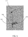
- the extension member 108 is capable of being moved relative to the base 106 between a retracted position (best seen in FIG. 4 ) and an extended position (best seen in FIG. 5 ).
- the driver 110 or other suitable technique can be used to raise and lower the extension member 108.
- the extension member 108 includes a registration surface that cooperates with a complementary surface in the driver 110.
- One non-limiting embodiment includes the driver 110 in the form of a nut capable of being turned and structured to engage a raised surface on the extension member 108.
- the registration surface on the extension member 108 can be a rack that is moved by an associated pinion or other suitable device.
- Other forms of the driver 10 are contemplated herein, such as but not limited to the rack and pinion/gearing approach discussed below with respect to FIGS. 7 and 8 .
- the extension member 108 can be enclosed in a covering, or can rest freely underneath the base 106 when in the retracted position.
- FIGS. 4-6 illustrate the extension member 108 that extends below a covering 116 when in the retracted position (best seen in FIG. 4 ), while the portion remaining below the base 106 is covered by the covering 116 when in the deployed position (best seen in FIG. 5 ). Any size and shape of covering 116 can be used.
- the arm 112 is used to reach from the base 106 to the filter element 72 when removing the element 72.
- the arm 112 can, but need not, be pivoted about the base 106 to allow the filter element 72 to be moved from an initial extraction position starting over the filter housing 68 just above its nested position, to a position in which the filter element 72 can be lowered into a container (e.g. a rubbish container) positioned to the side of the housing 68.
- the arm 112 can alternatively and/or additionally be structured to pivot about the extension member 108. The pivoting movement, whether about the base 106 or about the base 106 and extension member 108, is illustrated and discussed further below in FIGS. 9-11 .
- the arm 112 can also be formed as an extension member such as but not limited to a telescoping extendable mechanism. In other forms the arm 112 can be a simple rigid rod.
- FIG. 6 illustrated one embodiment in which the arm 112 can be pivoted about an axis transverse to the extension member 108 and stowed in a collapsed position.
- the arm 112 in the illustrated embodiment is pivoted about an axis formed through an attachment bracket (e.g. through use of a pin, hinge, etc) and moved to a position roughly parallel to an axis about which the extension member 108 can be deployed into position to extract the filter element 72.
- FIGS. 7-8 depict yet another embodiment of the filter removal tool 82 in which the driver 110 includes a gearing 118 which can take many different forms.
- the gearing 118 can include one or more gears useful to translate power provided from an external device (e.g. a pneumatic driver, an electric drill driver, electric power from a power outlet to an onboard actuator, etc) into mechanical work used to actuate the extension member 108.
- the driver 110 therefore, can include any number of useful interfaces to receive power from an external device.
- the driver 110 can include a stub configured to receive a socket driven by a pneumatic or electric driver, and in which the driver can in some forms additionally include one or more internal gears useful to engage the registration surface of the extension member 108.
- the driver 110 includes a pinion that can engage the extension member 108 in the form of a rack, such as are provided in a rack and pinion connection.
- a lock 120 can be provided to provide positive locking force to discourage relative movement of the extension member 108 and the base 106.
- the lock 120 can be used to discourage movement of the extension member 108 into the retracted position (e.g. the position shown in FIG. 4 ) to mitigate unintended premature retraction of the extension member 108.
- the lock 120 can be used to discourage any movement or movement into the extended position (e.g. shown in FIG. 5 ) unless otherwise unlocked by a user.
- the lock 120 can take many forms, one of which is a pawl used to engage gear teeth of one embodiment of the driver 110.
- the filter removal tool 82 can furthermore include a tank seat 122 useful to engage with the filter housing 68.
- a tank seat 122 can take many forms, can be made of any number of materials, and can be located in one or more positions about the tool 82. In the illustrated embodiment the tank seat 122 is located near the bottom of the tool as shown in FIG. 7 .
- the tank seat 122 can travel with the extension member 108, or can remain in place (e.g. in those embodiments where the extension member 10 includes a cover or other suitable stationary device).
- the anchor point can take on an additional form as seen in FIGS. 7 and 8 .
- a movable anchor point in the form of movable holes 114.
- One or more of the holes 114 or abutment surfaces can be pivoted about a pivot point to adjust the distance between the holes 114.
- the holes 114 can further be adjusted length away from some position.
- the V-shaped arrangement shown in FIG. 8 could include one or more holes 114 that can be extended further along the angle at which they are currently set as illustrated in the figure.
- the arm 112 can include a telescoping feature made possible via a bearing construction. Two such bearings 124 are shown in FIG. 8 .
- the bearings can take on any variety of forms including a simple contact bearing, roller bearing element, etc.
- the arm 112 can also include a hook or other suitable device 112 useful to engage the filter capture tool 80 and/or any other suitable structure associated with the filter element 72 (e.g. as discussed above) used to remove the filter element 72 from the housing 68.
- FIGS. 4-6 can also be used in the embodiment depicted in FIGS. 7-8 , and vice versa.
- the tank seat 122 shown in FIGS. 7-8 could be used in the embodiment depicted in FIGS. 4-6 .
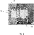
- FIGS. 9-11 one embodiment of the filter removal tool is shown removing a filter element 72 from a filter housing 68.
- Various positions are shown of the filter element 72 as it is moved from a position over the housing 68 to an external position away from the housing 68.
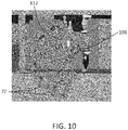
- the arm 112 can be seen in FIG. 10 positioned over the housing 68, while the same arm 112 is depicted in FIG. 11 as supporting the filter element 72 in a position external to the housing 68.
- the filter capture tool 80 and/or filter removal tool 82 can be deployed in many different manners to secure the filter in a nesting position, hoist the filter element 72 from the housing 68, and move the filter element 72 to an extracting position and/or lower the filter onto a support surface from which it can be removed for disposal.
- a nesting position can be used to refer to the position of the filter element 72 being nested into place within the housing 68 prior to removal.
- the extracting position can be used to refer to the position of the filter element 72 adequate for disposal into a container or intermediate processing platform prior to disposal, for example.
- a filter removal tool having: a base having an anchor connection device structured to be coupled to a support for removal of a filter, an extension member structured to extend from the base between a nesting position to an extracting position, the extension member having an axis of extension between the nesting position and the extracting position, a driver interconnected with the extension member and structured to move the extension member between the nesting position and the extracting position upon receipt of a power to drive the extension member, and an arm connected to the extension member and oriented transverse to the axis of extension such that the filter is cantilevered when attached to the filter removal tool, the filter removal tool further configured to pivot the arm about the axis of extension to rotate the filter away from a compressor filter housing, wherein the base of the filter removal tool is structured to support the torque and force loads associated with the cantilevered condition.
- a feature of the present application includes wherein the anchor connection device includes an abutment which a bolt can be engaged to secure the base to the support.
- anchor connection device is a first movable aperture structured to be movable relative to the extension member.
- Still another feature of the present application includes wherein the anchor connection device includes a second movable aperture, the first and second movable apertures structured to accommodate different configurations of the support, and wherein the first movable aperture is pivotable about an axis.
- extension member is a member that linearly extends from the base.
- Still yet another feature of the present application includes wherein the extension device is a rack having a plurality of teeth structured to engage a gear driven by work received via the driver.
- Yet still another feature of the present application further includes a gearing that can convert a first torque and first speed received by the driver to a second torque and second speed used to extend the extension member.
- a still yet further feature of the present application further includes a filter capture tool having a plurality of arms structured to engage an interior surface of a filter, the filter capture tool capable of being connected to the arm of the filter removal tool.
- a yet still further feature of the present application includes wherein the filter capture tool further includes a central threaded shaft affixed to a platform, the central threaded shaft having a complementary collar structured to move along a length of the central threaded shaft to deploy the plurality of arms, wherein the filter capture tool is capable of being connected to the filter removal tool via a hook and loop connection, and wherein the filter is a separator element.
- a feature of the present application includes wherein the engagement surface of each of the plurality of arms is a pivotable pad structured to engage an inner surface of a filter used in a compressor system.
- Another feature of the present application includes wherein each of the plurality of arms is connected to the collar via its own linkage member.
- Still another feature of the present application includes wherein the collar further includes an actuation member having the collar registration surface to enable movement of the collar along the length of the central shaft.
- Yet another feature of the present application includes wherein the shaft registration surface is a threaded formation.
- Still yet another feature of the present application includes wherein the actuation member is a threaded nut captured by the collar such that the nut is capable of rotation about the central shaft while the collar does not rotation about the central shaft, and wherein the filter is a separator element.
- Yet still another feature of the present application further includes a filter removal tool including an extension member capable of being deployed from a nested position to an extended position, the extension member attached to an arm that is configured to connect to the filter capture tool.
- a further feature of the present application includes wherein the filter removal tool further includes a base structured to attach to a filter housing and sustain loads imparted during removal of a filter when the plurality of arms are deployed to engage the filter, and wherein the extension member includes a rod having a rod registration surface.
- Yet another aspect of the present application provides a method comprising connecting a filter removal tool to a compressor filter housing, inserting a filter capture tool into the interior of a filter, expanding the filter capture tool to engage a side of the filter, connecting the filter capture tool to the filter removal tool, and raising an arm of the filter removal tool to extract the filter from the compressor filter housing
- a feature of the present application further includes pivoting the arm away from the base.
- the filter removal tool further includes an extension member connected to the arm, wherein raising the arm includes extending the extension member.
- Still another feature of the present application includes wherein pivoting the arm includes pivoting the extension member away from the base.
- connecting the filter includes seating a base of the filter removal tool against a flange of the compressor filter housing and aligning an anchor point to bolt holes formed in the compressor filter housing.
- Still yet another feature of the present application further includes which further includes installing a bolt used to secure a cover member of the compressor filter housing to secure a base of the filter removal tool to the compressor filter housing, and wherein the filter housing is a separator housing and wherein the filter is a separator element.
Landscapes
- Engineering & Computer Science (AREA)
- Mechanical Engineering (AREA)
- Chemical & Material Sciences (AREA)
- Chemical Kinetics & Catalysis (AREA)
- Filtering Of Dispersed Particles In Gases (AREA)
Abstract
Description
- The present invention generally relates to compressor system filter servicing, and more particularly, but not exclusively, to tools used to capture and/or remove compressor filters from filter housings.
- Providing tools useful to remove filters from filter housings remains an area of interest. Some existing systems have various shortcomings relative to certain applications. Accordingly, there remains a need for further contributions in this area of technology.
- One embodiment of the present invention is a unique tool useful to service a compressor. Other embodiments include apparatuses, systems, devices, hardware, methods, and combinations for servicing compressor system filters. Further embodiments, forms, features, aspects, benefits, and advantages of the present application shall become apparent from the description and figures provided herewith.
-
-
FIG. 1 depicts one embodiment of a compressor system. -
FIG. 2 depicts various aspects of one embodiment of a filter. -
FIG. 3 depicts one embodiment of a filter capture tool. -
FIG. 4 depicts an embodiment of a filter removal tool. -
FIG. 5 depicts an embodiment of a filter removal tool. -
FIG. 6 depicts an embodiment of a filter removal tool. -
FIG. 7 depicts an embodiment of a filter removal tool. -
FIG. 8 depicts an embodiment of a filter removal tool. -
FIG. 9 depicts operation of one embodiment of a filter removal tool. -
FIG. 10 depicts operation of one embodiment of a filter removal tool. -
FIG. 11 depicts operation of one embodiment of a filter removal tool. - For the purposes of promoting an understanding of the principles of the invention, reference will now be made to the embodiments illustrated in the drawings and specific language will be used to describe the same. It will nevertheless be understood that no limitation of the scope of the invention is thereby intended. Any alterations and further modifications in the described embodiments, and any further applications of the principles of the invention as described herein are contemplated as would normally occur to one skilled in the art to which the invention relates.
- With reference to
FIG. 1 , one embodiment of acompressor system 50 is shown which includes acompressor 52, aseparator 54, and afilter 56. Thecompressor 52 is used to pressurize anincoming gas 58 during which process it produces a mixedflow 60 of compressed gas and a byproduct of compression which is often an entrained stream of coolant or lubricant (e.g. a lubricant or coolant mist produced as a result of being used in the compression process of an oil filled screw compressor, among other possibilities). Further discussion below may refer to the byproduct of compression as the lubricant and/or the coolant, but no limitation is hereby intended regarding the use of the byproduct whether solely as a lubricant or solely as a coolant. Mention of either lubricant or coolant refers generally to the byproduct and not the intended use of the byproduct. Thus, any mention of lubricant can apply equally to the byproduct used primarily as a coolant, and vice versa. - The
compressor 52 can take on any variety of forms, and in one nonlimiting embodiment is a contact cooled compressor useful to compress a flow of air. Theseparator 54 is used to separate the mixedflow 60 to produce a cleaner flow compressedgas 62 and a flow of coolant/lubricant 64. Thefilter 56 can return a cleaner flow of lubricant/coolant 66 to thecompressor 52 while retaining contaminant in a filtering media. Though thecompressor system 50 is shown with just acompressor 52,separator 54, andfilter 56, other embodiments can include further devices, such as dryers, etc. - Turning now to
FIG. 2 , a schematic is shown of one embodiment of thefilter 56 which includes afilter housing 68,housing cover 70, andfilter element 72. Though thefilter element 72 can be any shape, size, configuration, etc, the illustrated form depicts theelement 72 having an annular shape with open interior 73, a filter flange 74 located near the top, and a filter media 76 beneath the flange 74. During installation and/or servicing of thefilter element 72 thecover 70 is removed to gain access to the interior of thefilter housing 68. Thecover 70 can be coupled to thehousing 68 using any variety of forms, and in one nonlimiting embodiment is affixed using a series of bolts or threaded lugs passed into either or both of holes 78 in thecover 70 and/orhousing 68. To set forth just one nonlimiting embodiment, bolts can be passed through holes 78 in thecover 70 and into apertures 78 in thehousing 68. The bolts can be affixed using nuts on the underside of a flange in thehousing 68, or can be received in tapped apertures formed in thehousing 68. - Although the embodiment discussed above in
FIG. 2 (and referred in the description below) is described relative to thefilter 56, it will be appreciated that such housing andelement 72 can be equally applicable to theseparator 54. For example, some embodiments of theseparator 54 can include a separator element that assists in separating lubricant from the compressed gas, but in so doing also performs a filtering function. Examples of such a device can include a separator element having a filtering media of glass fibers. The separator element, therefore, can serve as a filter. Thus, any mention herein of a filter element, filter, etc can be equally applicable to a separator and separator element that functions as a filter. No limitation is intended, and nothing can be construed, as limiting a filter element to just those elements associated with a filter mechanism placed downstream of a separator. Those elements within separators that also serve in some role as filters are also to be included. -
FIGS. 3-6 depicts various embodiments of afilter capture tool 80 and a filter removal tool 82 a useful to extract thefilter element 72 from thefilter housing 68 and/or replace thefilter element 72 into thehousing 68. Such devices can be used as aids in removing heavy and/or awkward filters. In some applications the filter intended to be serviced can weigh close to 80 pounds. -
FIG. 3 depicts one form of thefilter capture tool 80 which includes abase 84, acentral shaft 86 that extends from thebase 84, and acollar 88 which can be adjusted in position along the length of theshaft 86. Thecapture tool 80 also includesarms 90 which extend from thebase 84 and are connected to thecollar 88 vialinkage 92. Thearms 90 in the illustrated embodiment are coupled to the base via a pivoting connection (e.g. a hinge or pin, etc) and connected to thelinkage 92 via a pivoting connection (e.g. a hinge or pin, etc). Thelinkage 92 in the illustrated embodiment is also coupled to thecollar 88 via a pivoting connection (e.g. a hinge or pin, etc). Movement of thecollar 88 along thecentral shaft 86 causes corresponding movement in thelinkage 92 andarm 90. Downward movement of thecollar 88 causes thearms 90 to deploy radially outward away from theshaft 86. - The
arms 90 include anengagement surface 94 typically but not always located at the end which is used to press against the inside of thefilter element 72 as thearms 90 are deployed. The illustrated embodiment depict one nonlimiting form of anengagement surface 94 in the form ofcontact pads 96 which are attached to thearms 90 through a pivoting arrangement. Thecontact pads 96 can include any type of material and arrangement sufficient to engage and capture thefilter element 72 for removal from thehousing 68. In one nonlimiting form thecontact pads 96 can be rubber pads. - Though the illustrated embodiment depicts the
capture tool 80 with twoseparate arms 90, any number of arms can be used. In one nonlimiting embodiment, thecapture tool 80 includes three separate arms that can be arranged equidistant from one another. Additionally and/or alternatively, thearms 90 can provide about 18" diameter in the deployed position when used to engage the inner side of thefilter element 72. - In one form the
central shaft 86 includes a registration surface which is complementary to a registration surface in thecollar 88, where the interaction of the registration surfaces enables relative movement between thecollar 88 and thecentral shaft 86. In one nonlimiting form thecentral shaft 86 is threaded and is structured to engage a threaded nut in thecollar 88. - The
collar 88 can take on a variety of forms useful to move along thecentral shaft 86 and actuate thearms 90 between their retracted and deployed positions. In one form depicted inFIG. 3 , thecollar 88 includes aplatform 98 which supports arotatable nut 100 captured by theplatform 98 but otherwise free to turn relative to theplatform 98. Theplatform 98 can provide the structural connection point to thelinkages 92. - The
collar 88 can, but need not, include and/or be connected to the base 84 with an energy storage device. In one form the energy storage device is aspring 102. The energy storage device can be used to oppose motion of thecollar 88 in a certain direction. For example, thespring 102 can be attached to thebase 84 and pre-loaded to force thearms 90 in a deployed condition so that during removal of thefilter element 72 from thehousing 68 thecapture tool 80 maintains a positive grip on thefilter element 72 to prevent inadvertent retraction of thearms 90 and subsequent dropping of theelement 72. Other conditions are also contemplated. - The
filter capture tool 80 can include a connection point useful to engage thefilter removal tool 82. Such a connection point can take on many forms, one nonlimiting example of which is found inring 104 illustrated inFIG. 3 . The connection point can be an enclosed ring, a hook, a D loop, an aperture through which a bolt can be passed to attach thecapture tool 80 to theremoval tool 82, etc etc. In one form thefilter capture tool 80 may not include such a connection point, but rather afilter element 72 itself may include such an attachment point. For example, thefilter element 72 could be formed or be connected with a member useful to connect to theremoval tool 82. In one nonlimiting example, thefilter element 72 itself may include a connection point, such as a bracket, spanner, etc that extends into and/or across the open space 73. In such an embodiment thefilter capture tool 80 may not be needed and only theremoval tool 82 used to extract afilter element 72 from thefilter housing 68. - Various embodiments are contemplated for either a connection point associated with the filter, a mechanism coupled to the filter, or the
filter capture tool 80. Any of the connection types contemplated for one applies equally to the others. Thus, in some forms while it is contemplated for the filter element to have three D-rings on the top for attachment to the removal tool (either aligned in a line, side by side, etc to provide various attachment points), it would also be contemplated that the same arrangement of multiple D-rings could also be used for the other connection points associated with the filter. -
FIGS. 4-6 depict an embodiment of thefilter removal tool 82 which includes abase 106,extension member 108,driver 110, andarm 112. Thefilter removal tool 82 can be secured in place using an anchor to remove thefilter element 72 from thefilter housing 68. Such an anchor can take many forms and can be secured to a number of different items, such as but not limited to thefilter housing 68. - An anchor point formed in the base 106 can take on a number of different configurations, shapes and/or sizes. In one nonlimiting example, the
filter removal tool 82 can be attached to the holes 78 of thehousing 68 through use of the same bolt used to secure thecover 70 to thehousing 68. The anchor points can alternatively be a lug or other suitable device that extends from the base 106 or thehousing 68 to provide attachment of thebase 106. In those cases using a bolt or other suitable device, such a bolt can be inserted intoholes 114 formed in thebase 106. In another additional and/or alternative embodiment the anchor points can include abutment surface whether or not formed as an enclosed passage. For example, an anchor point can take the form of a concave half-moon shape in lieu of a fully enclosed hole. - Anchor points whether or not in the form of bolts and bolt holes can be a single attachment/load point, but other embodiments can take on any number of attachment points or load paths. To set forth just one nonlimiting example, four
holes 114 are depicted in the illustrated embodiment of thebase 106, but fewer ormore holes 114 can be provided. Furthermore, though more than one anchor point can be provided, not all anchor points need be used in any given application. In those embodiments which include more than one anchor point, the various anchor points can, but need not, be identical as in the illustrated embodiment. For example, one anchor point in a multi-anchor point embodiment can be a through-hole to receive a bolt while the other anchor point is a lug. Other variations are also contemplated. - Depending on the specific configuration of the
filter housing 68, the anchor point(s) can be tailored to match corresponding attachment points in thecompressor filter housings 68. For example, theholes 114 can be arranged to be adapted to any different number ofhousings 68. For example, theholes 114 on the near side of the base 106 (i.e. those with the lead lines attached) can be spaced apart to fit one type ofhousing 68, the holes on the other size of the base can be spaced apart to fit another type of housing, etc. Thebase 106 is depicted as a rectangular box having an open interior with cutouts formed in each side, but other variations are also contemplated herein. Given the nature of the loads imparted to the base 106 during operation of thetool 82, however, thebase 106 is structured to carry both normal loads and torques as thefilter element 72 is extracted from thehousing 68. - The
extension member 108 is capable of being moved relative to the base 106 between a retracted position (best seen inFIG. 4 ) and an extended position (best seen inFIG. 5 ). Thedriver 110 or other suitable technique can be used to raise and lower theextension member 108. In one form theextension member 108 includes a registration surface that cooperates with a complementary surface in thedriver 110. One non-limiting embodiment includes thedriver 110 in the form of a nut capable of being turned and structured to engage a raised surface on theextension member 108. The registration surface on theextension member 108 can be a rack that is moved by an associated pinion or other suitable device. Other forms of the driver 10 are contemplated herein, such as but not limited to the rack and pinion/gearing approach discussed below with respect toFIGS. 7 and8 . - The
extension member 108 can be enclosed in a covering, or can rest freely underneath the base 106 when in the retracted position. For example,FIGS. 4-6 illustrate theextension member 108 that extends below a covering 116 when in the retracted position (best seen inFIG. 4 ), while the portion remaining below thebase 106 is covered by the covering 116 when in the deployed position (best seen inFIG. 5 ). Any size and shape of covering 116 can be used. - The
arm 112 is used to reach from the base 106 to thefilter element 72 when removing theelement 72. Thearm 112 can, but need not, be pivoted about the base 106 to allow thefilter element 72 to be moved from an initial extraction position starting over thefilter housing 68 just above its nested position, to a position in which thefilter element 72 can be lowered into a container (e.g. a rubbish container) positioned to the side of thehousing 68. Thearm 112 can alternatively and/or additionally be structured to pivot about theextension member 108. The pivoting movement, whether about the base 106 or about thebase 106 andextension member 108, is illustrated and discussed further below inFIGS. 9-11 . Furthermore, thearm 112 can also be formed as an extension member such as but not limited to a telescoping extendable mechanism. In other forms thearm 112 can be a simple rigid rod. -
FIG. 6 illustrated one embodiment in which thearm 112 can be pivoted about an axis transverse to theextension member 108 and stowed in a collapsed position. Thearm 112 in the illustrated embodiment is pivoted about an axis formed through an attachment bracket (e.g. through use of a pin, hinge, etc) and moved to a position roughly parallel to an axis about which theextension member 108 can be deployed into position to extract thefilter element 72. -
FIGS. 7-8 depict yet another embodiment of thefilter removal tool 82 in which thedriver 110 includes agearing 118 which can take many different forms. Thegearing 118 can include one or more gears useful to translate power provided from an external device (e.g. a pneumatic driver, an electric drill driver, electric power from a power outlet to an onboard actuator, etc) into mechanical work used to actuate theextension member 108. Thedriver 110, therefore, can include any number of useful interfaces to receive power from an external device. In one nonlimiting form thedriver 110 can include a stub configured to receive a socket driven by a pneumatic or electric driver, and in which the driver can in some forms additionally include one or more internal gears useful to engage the registration surface of theextension member 108. In one form thedriver 110 includes a pinion that can engage theextension member 108 in the form of a rack, such as are provided in a rack and pinion connection. - In some forms a
lock 120 can be provided to provide positive locking force to discourage relative movement of theextension member 108 and thebase 106. In one form thelock 120 can be used to discourage movement of theextension member 108 into the retracted position (e.g. the position shown inFIG. 4 ) to mitigate unintended premature retraction of theextension member 108. In other forms thelock 120 can be used to discourage any movement or movement into the extended position (e.g. shown inFIG. 5 ) unless otherwise unlocked by a user. Thelock 120 can take many forms, one of which is a pawl used to engage gear teeth of one embodiment of thedriver 110. - The
filter removal tool 82 can furthermore include atank seat 122 useful to engage with thefilter housing 68. Such atank seat 122 can take many forms, can be made of any number of materials, and can be located in one or more positions about thetool 82. In the illustrated embodiment thetank seat 122 is located near the bottom of the tool as shown inFIG. 7 . Thetank seat 122 can travel with theextension member 108, or can remain in place (e.g. in those embodiments where the extension member 10 includes a cover or other suitable stationary device). - The anchor point can take on an additional form as seen in
FIGS. 7 and8 . A movable anchor point in the form ofmovable holes 114. One or more of theholes 114 or abutment surfaces can be pivoted about a pivot point to adjust the distance between theholes 114. In another alternative and/or additional embodiment, theholes 114 can further be adjusted length away from some position. For example, the V-shaped arrangement shown inFIG. 8 could include one ormore holes 114 that can be extended further along the angle at which they are currently set as illustrated in the figure. - The
arm 112 can include a telescoping feature made possible via a bearing construction. Twosuch bearings 124 are shown inFIG. 8 . The bearings can take on any variety of forms including a simple contact bearing, roller bearing element, etc. - The
arm 112 can also include a hook or othersuitable device 112 useful to engage thefilter capture tool 80 and/or any other suitable structure associated with the filter element 72 (e.g. as discussed above) used to remove thefilter element 72 from thehousing 68. - Features illustrated in the embodiment depicted in
FIGS. 4-6 can also be used in the embodiment depicted inFIGS. 7-8 , and vice versa. To set forth just one nonlimiting example, thetank seat 122 shown inFIGS. 7-8 could be used in the embodiment depicted inFIGS. 4-6 . No limitation is hereby intended regarding the features shown in any given embodiment being limited to only that embodiment. - Turning now to
FIGS. 9-11 , one embodiment of the filter removal tool is shown removing afilter element 72 from afilter housing 68. Various positions are shown of thefilter element 72 as it is moved from a position over thehousing 68 to an external position away from thehousing 68. It will thus be appreciated that although many different images are shown of thefilter element 72, in fact such an illustration is merely showing the various intermediate positions of thefilter element 72 during a removal or installation process. Thearm 112 can be seen inFIG. 10 positioned over thehousing 68, while thesame arm 112 is depicted inFIG. 11 as supporting thefilter element 72 in a position external to thehousing 68. - It will be appreciated herein that the
filter capture tool 80 and/or filterremoval tool 82 can be deployed in many different manners to secure the filter in a nesting position, hoist thefilter element 72 from thehousing 68, and move thefilter element 72 to an extracting position and/or lower the filter onto a support surface from which it can be removed for disposal. As used herein, a nesting position can be used to refer to the position of thefilter element 72 being nested into place within thehousing 68 prior to removal. The extracting position can be used to refer to the position of thefilter element 72 adequate for disposal into a container or intermediate processing platform prior to disposal, for example. - For the avoidance of doubt, the subject-matter of the present application may extend to any combination of the following aspects and features.
- One aspect of the present application includes an apparatus comprising a filter removal tool having: a base having an anchor connection device structured to be coupled to a support for removal of a filter, an extension member structured to extend from the base between a nesting position to an extracting position, the extension member having an axis of extension between the nesting position and the extracting position, a driver interconnected with the extension member and structured to move the extension member between the nesting position and the extracting position upon receipt of a power to drive the extension member, and an arm connected to the extension member and oriented transverse to the axis of extension such that the filter is cantilevered when attached to the filter removal tool, the filter removal tool further configured to pivot the arm about the axis of extension to rotate the filter away from a compressor filter housing, wherein the base of the filter removal tool is structured to support the torque and force loads associated with the cantilevered condition.
- A feature of the present application includes wherein the anchor connection device includes an abutment which a bolt can be engaged to secure the base to the support.
- Another feature of the present application includes wherein the anchor connection device is a first movable aperture structured to be movable relative to the extension member.
- Still another feature of the present application includes wherein the anchor connection device includes a second movable aperture, the first and second movable apertures structured to accommodate different configurations of the support, and wherein the first movable aperture is pivotable about an axis.
- Yet another feature of the present application includes wherein the extension member is a member that linearly extends from the base.
- Still yet another feature of the present application includes wherein the extension device is a rack having a plurality of teeth structured to engage a gear driven by work received via the driver.
- Yet still another feature of the present application further includes a gearing that can convert a first torque and first speed received by the driver to a second torque and second speed used to extend the extension member.
- A still yet further feature of the present application further includes a filter capture tool having a plurality of arms structured to engage an interior surface of a filter, the filter capture tool capable of being connected to the arm of the filter removal tool.
- A yet still further feature of the present application includes wherein the filter capture tool further includes a central threaded shaft affixed to a platform, the central threaded shaft having a complementary collar structured to move along a length of the central threaded shaft to deploy the plurality of arms, wherein the filter capture tool is capable of being connected to the filter removal tool via a hook and loop connection, and wherein the filter is a separator element.
- Another aspect of the present application provides an apparatus comprising a filter capture tool having a central shaft affixed to a base and a collar structured to move along a length of the central shaft, the central shaft having a shaft registration surface and the collar having a collar registration surface complementary to the shaft registration surface such that relative movement of the collar registration surface to the shaft registration surface enables the collar to move along the length of the central shaft, the filter capture tool further including a plurality of arms that extend from and are pivotably attached to the base, the plurality of arms each including an engagement surface structured to engage an inner surface of a filter used in a compressor system, the plurality of arms connected to the collar via a linkage member.
- A feature of the present application includes wherein the engagement surface of each of the plurality of arms is a pivotable pad structured to engage an inner surface of a filter used in a compressor system.
- Another feature of the present application includes wherein each of the plurality of arms is connected to the collar via its own linkage member.
- Still another feature of the present application includes wherein the collar further includes an actuation member having the collar registration surface to enable movement of the collar along the length of the central shaft.
- Yet another feature of the present application includes wherein the shaft registration surface is a threaded formation.
- Still yet another feature of the present application includes wherein the actuation member is a threaded nut captured by the collar such that the nut is capable of rotation about the central shaft while the collar does not rotation about the central shaft, and wherein the filter is a separator element.
- Yet still another feature of the present application further includes a filter removal tool including an extension member capable of being deployed from a nested position to an extended position, the extension member attached to an arm that is configured to connect to the filter capture tool.
- A further feature of the present application includes wherein the filter removal tool further includes a base structured to attach to a filter housing and sustain loads imparted during removal of a filter when the plurality of arms are deployed to engage the filter, and wherein the extension member includes a rod having a rod registration surface.
- Yet another aspect of the present application provides a method comprising connecting a filter removal tool to a compressor filter housing, inserting a filter capture tool into the interior of a filter, expanding the filter capture tool to engage a side of the filter, connecting the filter capture tool to the filter removal tool, and raising an arm of the filter removal tool to extract the filter from the compressor filter housing
- A feature of the present application further includes pivoting the arm away from the base.
- Another feature of the present application includes wherein the filter removal tool further includes an extension member connected to the arm, wherein raising the arm includes extending the extension member.
- Still another feature of the present application includes wherein pivoting the arm includes pivoting the extension member away from the base.
- Yet still another feature of the present application includes wherein the connecting the filter includes seating a base of the filter removal tool against a flange of the compressor filter housing and aligning an anchor point to bolt holes formed in the compressor filter housing.
- Still yet another feature of the present application further includes which further includes installing a bolt used to secure a cover member of the compressor filter housing to secure a base of the filter removal tool to the compressor filter housing, and wherein the filter housing is a separator housing and wherein the filter is a separator element.
- While the invention has been illustrated and described in detail in the drawings and foregoing description, the same is to be considered as illustrative and not restrictive in character, it being understood that only the preferred embodiments have been shown and described and that all changes and modifications that come within the spirit of the inventions are desired to be protected. It should be understood that while the use of words such as preferable, preferably, preferred or more preferred utilized in the description above indicate that the feature so described may be more desirable, it nonetheless may not be necessary and embodiments lacking the same may be contemplated as within the scope of the invention, the scope being defined by the claims that follow. In reading the claims, it is intended that when words such as "a," "an," "at least one," or "at least one portion" are used there is no intention to limit the claim to only one item unless specifically stated to the contrary in the claim. When the language "at least a portion" and/or "a portion" is used the item can include a portion and/or the entire item unless specifically stated to the contrary. Unless specified or limited otherwise, the terms "mounted," "connected," "supported," and "coupled" and variations thereof are used broadly and encompass both direct and indirect mountings, connections, supports, and couplings. Further, "connected" and "coupled" are not restricted to physical or mechanical connections or couplings.
Claims (15)
- A filter removal tool having:a base having an anchor connection device structured to be coupled to a support for removal of a filter;an extension member structured to extend from the base between a nesting position to an extracting position, the extension member having an axis of extension between the nesting position and the extracting position;a driver interconnected with the extension member and structured to move the extension member between the nesting position and the extracting position upon receipt of a power to drive the extension member; andan arm connected to the extension member and oriented transverse to the axis of extension such that the filter is cantilevered when attached to the filter removal tool, the filter removal tool further configured to pivot the arm about the axis of extension to rotate the filter away from a compressor filter housing, wherein the base of the filter removal tool is structured to support the torque and force loads associated with the cantilevered condition.
- The filter removal tool of claim 1, wherein the anchor connection device is a first movable aperture structured to be movable relative to the extension member.
- The filter removal tool of claim 2, wherein the anchor connection device includes a second movable aperture, the first and second movable apertures structured to accommodate different configurations of the support, and wherein the first movable aperture is pivotable about an axis.
- The filter removal tool of any preceding claim, wherein the extension member is a rack having a plurality of teeth structured to engage a gear driven by work received via the driver.
- The filter removal tool of any preceding claim, which further includes a gearing that can convert a first torque and first speed received by the driver to a second torque and second speed used to extend the extension member.
- A filter capture tool having a central shaft affixed to a base and a collar structured to move along a length of the central shaft, the central shaft having a shaft registration surface and the collar having a collar registration surface complementary to the shaft registration surface such that relative movement of the collar registration surface to the shaft registration surface enables the collar to move along the length of the central shaft, the filter capture tool further including a plurality of arms that extend from and are pivotably attached to the base, the plurality of arms each including an engagement surface structured to engage an inner surface of a filter used in a compressor system, the plurality of arms connected to the collar via a linkage member.
- The filter capture tool of claim 6, wherein the engagement surface of each of the plurality of arms is a pivotable pad structured to engage an inner surface of a filter used in a compressor system.
- The filter capture tool of claim 6 or 7, wherein the collar further includes an actuation member having the collar registration surface to enable movement of the collar along the length of the central shaft.
- The filter capture tool of any of claims 6 to 8, wherein the shaft registration surface is a threaded formation; and
wherein the actuation member is a threaded nut captured by the collar such that the nut is capable of rotation about the central shaft while the collar does not rotate about the central shaft, and wherein the filter is a separator element. - An apparatus comprising the filter removal tool of any of claims 1 to 5 and the filter capture tool of any of claims 6 to 9, wherein the filter capture tool is capable of being connected to the arm of the filter removal tool.
- A method comprising:connecting a filter removal tool to a compressor filter housing;inserting a filter capture tool into the interior of a filter;expanding the filter capture tool to engage a side of the filter;connecting the filter capture tool to the filter removal tool; andraising an arm of the filter removal tool to extract the filter from the compressor filter housing.
- The method of claim 11, which further includes pivoting the arm away from a base of the filter removal tool.
- The method of claim 11 or 12, wherein the filter removal tool further includes an extension member connected to the arm, wherein raising the arm includes extending the extension member.
- The method of any of claims 11 to 13, wherein the connecting the filter includes seating a base of the filter removal tool against a flange of the compressor filter housing and aligning an anchor point to bolt holes formed in the compressor filter housing.
- The method of claim 14, which further includes installing a bolt used to secure a cover member of the compressor filter housing to secure a base of the filter removal tool to the compressor filter housing, and wherein the filter housing is a separator housing and wherein the filter is a separator element.
Applications Claiming Priority (1)
| Application Number | Priority Date | Filing Date | Title |
|---|---|---|---|
| US15/420,632 US20180214799A1 (en) | 2017-01-31 | 2017-01-31 | Compressor filter tool useful in service calls |
Publications (1)
| Publication Number | Publication Date |
|---|---|
| EP3354409A1 true EP3354409A1 (en) | 2018-08-01 |
Family
ID=61132118
Family Applications (1)
| Application Number | Title | Priority Date | Filing Date |
|---|---|---|---|
| EP18154372.9A Withdrawn EP3354409A1 (en) | 2017-01-31 | 2018-01-31 | Compressor filter tool useful in service calls |
Country Status (2)
| Country | Link |
|---|---|
| US (1) | US20180214799A1 (en) |
| EP (1) | EP3354409A1 (en) |
Families Citing this family (2)
| Publication number | Priority date | Publication date | Assignee | Title |
|---|---|---|---|---|
| FR3098141B1 (en) * | 2019-07-03 | 2022-01-28 | Orano Ds Demantelement Et Services | Tool for recovering a solid element, in particular a radioactive material, comprising a capture head and a cup |
| CN114149037B (en) * | 2021-11-12 | 2023-09-01 | 淮南师范学院 | Aquaculture sewage pretreatment device |
Citations (11)
| Publication number | Priority date | Publication date | Assignee | Title |
|---|---|---|---|---|
| US3304601A (en) * | 1965-08-09 | 1967-02-21 | Henry M Torres | Apparatus for pulling retainers or seals and the like |
| US3886823A (en) * | 1974-03-21 | 1975-06-03 | Raymond Lee Organization Inc | Radiator cap remover tool |
| US4057889A (en) * | 1976-03-19 | 1977-11-15 | Ferguson Marvin D | Engine cylinder sleeve puller and method |
| US5247727A (en) * | 1992-07-22 | 1993-09-28 | Pfizer Inc. | Ceramic membrane removal tool |
| DE29502569U1 (en) * | 1995-02-16 | 1995-03-30 | Dagn, Josef, Kössen, Tirol | Liquid disposal device |
| US20030037425A1 (en) * | 2001-08-27 | 2003-02-27 | Eli Sawaya | Wheel pulling apparatus |
| US20040139591A1 (en) * | 2003-01-07 | 2004-07-22 | Valtra, Inc. | Alignment clamp |
| US7322087B1 (en) * | 2007-02-23 | 2008-01-29 | Chih Kuo Hu | Bearing installing and removing tool |
| US20120151728A1 (en) * | 2010-12-15 | 2012-06-21 | Wei Nan Shen | Tool device for dismantling bearing element |
| US20130291957A1 (en) * | 2012-05-04 | 2013-11-07 | Caterpillar Inc. | Snap ring installation and removal tool |
| DE202016105086U1 (en) * | 2016-09-13 | 2016-09-30 | Jun-Fan Chen | pressure tool |
Family Cites Families (1)
| Publication number | Priority date | Publication date | Assignee | Title |
|---|---|---|---|---|
| US20100224034A1 (en) * | 2009-03-06 | 2010-09-09 | Brian Joseph Fitzpatrick | Compression Nut Removal Device |
-
2017
- 2017-01-31 US US15/420,632 patent/US20180214799A1/en not_active Abandoned
-
2018
- 2018-01-31 EP EP18154372.9A patent/EP3354409A1/en not_active Withdrawn
Patent Citations (11)
| Publication number | Priority date | Publication date | Assignee | Title |
|---|---|---|---|---|
| US3304601A (en) * | 1965-08-09 | 1967-02-21 | Henry M Torres | Apparatus for pulling retainers or seals and the like |
| US3886823A (en) * | 1974-03-21 | 1975-06-03 | Raymond Lee Organization Inc | Radiator cap remover tool |
| US4057889A (en) * | 1976-03-19 | 1977-11-15 | Ferguson Marvin D | Engine cylinder sleeve puller and method |
| US5247727A (en) * | 1992-07-22 | 1993-09-28 | Pfizer Inc. | Ceramic membrane removal tool |
| DE29502569U1 (en) * | 1995-02-16 | 1995-03-30 | Dagn, Josef, Kössen, Tirol | Liquid disposal device |
| US20030037425A1 (en) * | 2001-08-27 | 2003-02-27 | Eli Sawaya | Wheel pulling apparatus |
| US20040139591A1 (en) * | 2003-01-07 | 2004-07-22 | Valtra, Inc. | Alignment clamp |
| US7322087B1 (en) * | 2007-02-23 | 2008-01-29 | Chih Kuo Hu | Bearing installing and removing tool |
| US20120151728A1 (en) * | 2010-12-15 | 2012-06-21 | Wei Nan Shen | Tool device for dismantling bearing element |
| US20130291957A1 (en) * | 2012-05-04 | 2013-11-07 | Caterpillar Inc. | Snap ring installation and removal tool |
| DE202016105086U1 (en) * | 2016-09-13 | 2016-09-30 | Jun-Fan Chen | pressure tool |
Also Published As
| Publication number | Publication date |
|---|---|
| US20180214799A1 (en) | 2018-08-02 |
Similar Documents
| Publication | Publication Date | Title |
|---|---|---|
| US11192115B2 (en) | Dual-shaft shredder having a quick-change device | |
| JP5931893B2 (en) | Engine mounted system | |
| US10801593B2 (en) | Strut extender mechanism | |
| US20180214799A1 (en) | Compressor filter tool useful in service calls | |
| MX2014015831A (en) | Apparatus and method for a crusher with an inverted cylinder. | |
| AU2011202369A1 (en) | Arrangement for lifting a tower wall portion of a wind turbine and method for lifting a tower wall portion of a wind turbine | |
| US20200017239A1 (en) | Apparatus for supporting an object adjacent to an aircraft | |
| EP2093436A2 (en) | Fastening device and an unlocking and placement tool for such a fastening device | |
| CN105074137B (en) | engine washout collector | |
| FI2978942T3 (en) | Cantilever sliding carriage for assembly and disassembly of a rotor block | |
| CN101517246B (en) | Actuator unit comprising force amplification device | |
| US12269149B2 (en) | Engine component removal tool | |
| EP3369690A1 (en) | Jib coupling system for jib stowage | |
| CN201769176U (en) | Automobile suspension spiral spring compressor | |
| CN103321672B (en) | Rescue promotes cabin and disengaging gear | |
| US20090304488A1 (en) | Engine Filter Lifting Device | |
| CN101890631B (en) | Grinding wheel automatic assembly and disassembly device of heavy numerical control roll grinder | |
| CN101875063B (en) | Manual clamping device of wire drawing machine | |
| CN201618740U (en) | Manual clamping device of drawing-wire machine | |
| CN201423519Y (en) | Heavy digital control roll grinder automatic grinding wheel dissembling and assembling device | |
| CN106494479B (en) | A kind of engine cylinder cover line reprocesses vehicle | |
| CN103831605A (en) | Dismounting and mounting integrated machine for automobile steering knuckle vertical shaft | |
| JP6367330B2 (en) | Vertical roller mill | |
| CN212273393U (en) | Pipeline jacking tilting mechanism | |
| CN102774448A (en) | Automobile body lifting appliance of automobile chassis line |
Legal Events
| Date | Code | Title | Description |
|---|---|---|---|
| PUAI | Public reference made under article 153(3) epc to a published international application that has entered the european phase |
Free format text: ORIGINAL CODE: 0009012 |
|
| STAA | Information on the status of an ep patent application or granted ep patent |
Free format text: STATUS: THE APPLICATION HAS BEEN PUBLISHED |
|
| AK | Designated contracting states |
Kind code of ref document: A1 Designated state(s): AL AT BE BG CH CY CZ DE DK EE ES FI FR GB GR HR HU IE IS IT LI LT LU LV MC MK MT NL NO PL PT RO RS SE SI SK SM TR |
|
| AX | Request for extension of the european patent |
Extension state: BA ME |
|
| STAA | Information on the status of an ep patent application or granted ep patent |
Free format text: STATUS: REQUEST FOR EXAMINATION WAS MADE |
|
| 17P | Request for examination filed |
Effective date: 20190131 |
|
| RBV | Designated contracting states (corrected) |
Designated state(s): AL AT BE BG CH CY CZ DE DK EE ES FI FR GB GR HR HU IE IS IT LI LT LU LV MC MK MT NL NO PL PT RO RS SE SI SK SM TR |
|
| RAP1 | Party data changed (applicant data changed or rights of an application transferred) |
Owner name: INGERSOLL-RAND INDUSTRIAL U.S., INC. |
|
| STAA | Information on the status of an ep patent application or granted ep patent |
Free format text: STATUS: EXAMINATION IS IN PROGRESS |
|
| 17Q | First examination report despatched |
Effective date: 20200730 |
|
| STAA | Information on the status of an ep patent application or granted ep patent |
Free format text: STATUS: THE APPLICATION IS DEEMED TO BE WITHDRAWN |
|
| 18D | Application deemed to be withdrawn |
Effective date: 20210721 |