EP3354390A1 - Wire electrical discharge machine - Google Patents
Wire electrical discharge machine Download PDFInfo
- Publication number
- EP3354390A1 EP3354390A1 EP18154015.4A EP18154015A EP3354390A1 EP 3354390 A1 EP3354390 A1 EP 3354390A1 EP 18154015 A EP18154015 A EP 18154015A EP 3354390 A1 EP3354390 A1 EP 3354390A1
- Authority
- EP
- European Patent Office
- Prior art keywords
- current
- machining
- electrode
- electrical discharge
- power source
- Prior art date
- Legal status (The legal status is an assumption and is not a legal conclusion. Google has not performed a legal analysis and makes no representation as to the accuracy of the status listed.)
- Granted
Links
Images




Classifications
-
- B—PERFORMING OPERATIONS; TRANSPORTING
- B23—MACHINE TOOLS; METAL-WORKING NOT OTHERWISE PROVIDED FOR
- B23H—WORKING OF METAL BY THE ACTION OF A HIGH CONCENTRATION OF ELECTRIC CURRENT ON A WORKPIECE USING AN ELECTRODE WHICH TAKES THE PLACE OF A TOOL; SUCH WORKING COMBINED WITH OTHER FORMS OF WORKING OF METAL
- B23H7/00—Processes or apparatus applicable to both electrical discharge machining and electrochemical machining
- B23H7/02—Wire-cutting
-
- B—PERFORMING OPERATIONS; TRANSPORTING
- B23—MACHINE TOOLS; METAL-WORKING NOT OTHERWISE PROVIDED FOR
- B23H—WORKING OF METAL BY THE ACTION OF A HIGH CONCENTRATION OF ELECTRIC CURRENT ON A WORKPIECE USING AN ELECTRODE WHICH TAKES THE PLACE OF A TOOL; SUCH WORKING COMBINED WITH OTHER FORMS OF WORKING OF METAL
- B23H7/00—Processes or apparatus applicable to both electrical discharge machining and electrochemical machining
- B23H7/02—Wire-cutting
- B23H7/08—Wire electrodes
- B23H7/10—Supporting, winding or electrical connection of wire-electrode
-
- B—PERFORMING OPERATIONS; TRANSPORTING
- B23—MACHINE TOOLS; METAL-WORKING NOT OTHERWISE PROVIDED FOR
- B23H—WORKING OF METAL BY THE ACTION OF A HIGH CONCENTRATION OF ELECTRIC CURRENT ON A WORKPIECE USING AN ELECTRODE WHICH TAKES THE PLACE OF A TOOL; SUCH WORKING COMBINED WITH OTHER FORMS OF WORKING OF METAL
- B23H1/00—Electrical discharge machining, i.e. removing metal with a series of rapidly recurring electrical discharges between an electrode and a workpiece in the presence of a fluid dielectric
- B23H1/02—Electric circuits specially adapted therefor, e.g. power supply, control, preventing short circuits or other abnormal discharges
- B23H1/028—Electric circuits specially adapted therefor, e.g. power supply, control, preventing short circuits or other abnormal discharges for multiple gap machining
-
- B—PERFORMING OPERATIONS; TRANSPORTING
- B23—MACHINE TOOLS; METAL-WORKING NOT OTHERWISE PROVIDED FOR
- B23H—WORKING OF METAL BY THE ACTION OF A HIGH CONCENTRATION OF ELECTRIC CURRENT ON A WORKPIECE USING AN ELECTRODE WHICH TAKES THE PLACE OF A TOOL; SUCH WORKING COMBINED WITH OTHER FORMS OF WORKING OF METAL
- B23H11/00—Auxiliary apparatus or details, not otherwise provided for
-
- B—PERFORMING OPERATIONS; TRANSPORTING
- B23—MACHINE TOOLS; METAL-WORKING NOT OTHERWISE PROVIDED FOR
- B23H—WORKING OF METAL BY THE ACTION OF A HIGH CONCENTRATION OF ELECTRIC CURRENT ON A WORKPIECE USING AN ELECTRODE WHICH TAKES THE PLACE OF A TOOL; SUCH WORKING COMBINED WITH OTHER FORMS OF WORKING OF METAL
- B23H7/00—Processes or apparatus applicable to both electrical discharge machining and electrochemical machining
- B23H7/02—Wire-cutting
- B23H7/04—Apparatus for supplying current to working gap; Electric circuits specially adapted therefor
-
- B—PERFORMING OPERATIONS; TRANSPORTING
- B23—MACHINE TOOLS; METAL-WORKING NOT OTHERWISE PROVIDED FOR
- B23H—WORKING OF METAL BY THE ACTION OF A HIGH CONCENTRATION OF ELECTRIC CURRENT ON A WORKPIECE USING AN ELECTRODE WHICH TAKES THE PLACE OF A TOOL; SUCH WORKING COMBINED WITH OTHER FORMS OF WORKING OF METAL
- B23H7/00—Processes or apparatus applicable to both electrical discharge machining and electrochemical machining
- B23H7/02—Wire-cutting
- B23H7/08—Wire electrodes
-
- B—PERFORMING OPERATIONS; TRANSPORTING
- B23—MACHINE TOOLS; METAL-WORKING NOT OTHERWISE PROVIDED FOR
- B23H—WORKING OF METAL BY THE ACTION OF A HIGH CONCENTRATION OF ELECTRIC CURRENT ON A WORKPIECE USING AN ELECTRODE WHICH TAKES THE PLACE OF A TOOL; SUCH WORKING COMBINED WITH OTHER FORMS OF WORKING OF METAL
- B23H1/00—Electrical discharge machining, i.e. removing metal with a series of rapidly recurring electrical discharges between an electrode and a workpiece in the presence of a fluid dielectric
- B23H1/02—Electric circuits specially adapted therefor, e.g. power supply, control, preventing short circuits or other abnormal discharges
Definitions
- the present invention relates to a wire electrical discharge machine having a core retaining function for retaining cores during machining.
- Japanese Patent No. 5651091 discloses a method of cutting out a part from a workpiece with making partially welded spots in wire electrical discharge machining.
- the machining conditions are changed into conditions for welding. That is, high voltage load (voltage) for electrical discharge is lowered so as to suppress the machining current through the electrode gap and lengthen the time of voltage application.
- high voltage load (voltage) for electrical discharge is lowered so as to suppress the machining current through the electrode gap and lengthen the time of voltage application.
- part of the wire electrode is melted so that a core can be welded to the workpiece by the melted substance.
- a wire electrical discharge machine using a machining power source to apply a machining current across an electrode gap formed between a wire electrode and a workpiece to be machined and thereby perform electrical discharge machining on the workpiece includes: an electrode unit configured to supply the machining current to the electrode gap; a switch configured to change impedance between the machining power source and the electrode unit; and a controller configured to, at the time of a core retaining process, control the switch to set the impedance to be higher than the impedance in a cutting process and thereby suppress the machining current flowing through the electrode gap.
- the present invention it is possible to sufficiently suppress the machining current flowing through the electrode gap during a core retaining process without using an expensive machining power source that can output a wide range of voltage. Therefore, cores can be welded to the workpiece with an inexpensive configuration.
- FIG. 1 is a diagram showing a configuration example of a wire electrical discharge machine 12 according to a first embodiment of the present invention.
- the wire electrical discharge machine 12 performs electrical discharge machining by applying voltage across an electrode gap EG formed between a wire electrode 10 and an object to be machined (workpiece) W to flow a machining current (discharge current).
- the wire electrical discharge machine 12 machines the workpiece W by feeding the wire electrode 10 in the Z-direction toward the workpiece W while changing the relative position between the wire electrode 10 and the workpiece W on the XY-plane orthogonal to the Z-direction. That is, the wire electrode 10 is relatively moved along a predetermined path on the workpiece W to thereby machine the workpiece W. A core is formed during this cutting process.
- the wire electrical discharge machine 12 has a core retaining function for fixing the core that was formed during machining, to the workpiece W.
- the wire electrical discharge machine 12 includes a circuit (hereinafter referred to as a machining circuit) C1 for applying a voltage (machining voltage) Vm across the electrode gap EG to flow a machining current, and a controller 14 for controlling components of the wire electrical discharge machine 12 inclusive of the machining circuit C1.
- the machining circuit C1 includes an electrode unit 20, a power source (hereinafter referred to as a machining power source) 22, a switching element SWE1, and switches SW.
- the electrode unit 20 is adapted to supply machining current to the electrode gap EG and has first electrode parts 20a connected to the wire electrode 10 and a second electrode part 20b connected to the workpiece W.
- the first electrode parts 20a are made up of two electrode parts, one part being located on the upstream side of the workpiece W (on the upper side of the workpiece W in FIG. 1 ) while the other part being located on the downstream side of the workpiece W (on the lower side of the workpiece W in FIG. 1 ) with respect to the feeding direction of the wire electrode 10.
- the first electrode part 20a located upstream of the workpiece W is referred to as 20a1 whereas the first electrode part 20a located downstream of the workpiece W is referred to as 20a2.
- the machining power source 22 has a DC current power supply.
- the negative terminal (- terminal) of the machining power source 22 is connected to the wire electrode 10 (first electrode parts 20a), and the positive terminal (+ terminal) is connected to the workpiece W (the second electrode part 20b).
- the machining power source 22 may be configured to selectively apply one of the positive polarity voltage Vm and the negative polarity voltage Vm to the electrode gap EG.
- the electrode unit 20 and the machining power source 22 are connected by current supply lines 24.
- the current supply lines 24 include a first current supply line 24a that connects the machining power source 22 (negative terminal) with the first electrode parts 20a and a second current supply line 24b that connects the machining power source 22 (positive terminal) with the second electrode part 20b.
- the first current supply line 24a connected to the first electrode part 20a1 located upstream of the workpiece W is called 24a1 and the first current supply line 24a connected to the first electrode part 20a2 located downstream of the workpiece W is called 24a2.
- the switching element SWE1 is provided to supply machining current from the machining power source 22 to the electrode gap EG.
- the switching element SWE1 is arranged between the machining power source 22 and the electrode gap EG and connected in series with the machining power source 22 and the electrode gap EG.
- the switching element SWE1 is arranged between the machining power source 22 and the first electrode part 20a (the wire electrode 10) and connected in series with the machining power source 22 and the first electrode part 20a (the wire electrode 10). That is, the switching element SWE1 is disposed on the first current supply line 24a.
- the voltage Vm of the machining power source 22 is applied to the electrode gap EG so that a machining current flows through the electrode gap EG. That is, as the switching element SWE1 is turned on and off, application of the voltage Vm to the electrode gap EG is turned on and off accordingly.
- the switching element SWE1 may be a switching element such as an FET.
- the switching element SWE1 may be arranged between the machining power source 22 and the second electrode part 20b (the workpiece W) and connected in series with the machining power source 22 and the second electrode part 20b (the workpiece W). That is, the switching element SWE1 may be disposed on the second current supply line 24b. Alternatively, the two switching elements SWE1 may be arranged respectively between the machining power source 22 and the first electrode part 20a and between the machining power source 22 and the second electrode part 20b.
- the switches SW serve to change the impedance between the electrode unit 20 (electrode parts 20a, 20b) and the machining power source 22.
- the switches SW are provided for the first current supply lines 24a (24a1, 24a2) connected between the first electrode parts 20a (20a1, 20a2) and the machining power source 22.
- the switches SW are disposed on the first current supply lines 24a (24a1, 24a2).
- the switch SW provided for the first current supply line 24a1 is referred to as SW1
- the switch SW provided for the first current supply line 24a2 is referred to as SW2.
- the switch SW may be a switching element such as an FET.
- FIG. 2 is a diagram showing a specific configuration example of the first current supply lines 24a and the switches SW.
- Each of the first current supply lines 24a branches into a plurality of current lines BL, and the multiple branched current lines BL are each connected to the first electrode part 20a. At least one of current lines BL among the multiple branched current lines BL includes the switch SW.
- each of the first current supply lines 24a branches into three lines BL, and the switch SW is disposed on each of the lines BL.
- the current lines BL branched from the first current supply line 24a1 and connected to the first electrode part 20a1 are denoted by BL1
- the current lines BL branched from the first current supply line 24a2 and connected to the first electrode part 20a2 are denoted by BL2.
- the switches SW1 are disposed on the current lines BL1
- the switches SW2 are disposed on the current lines BL2.
- the controller 14 shown in FIG. 1 performs on-off control of the switching element SWE1 and the switches SW in accordance with machining conditions to thereby perform electrical discharge machining on the workpiece W.
- the controller 14 turns on (closes) all the switches SW and performs on-off control of the switching element SWE1 to machine the workpiece W.
- the controller 14 turns off (opens) at least one of the switches SW and performs on/off control of the switching element SWE1 so as to melt part of the wire electrode 10 while perform cutting to thereby weld and stick the core to the workpiece W with the melted material.
- the controller 14 performs machining by moving the wire electrode 10 along a predetermined path on the workpiece W to be machined.
- the controller 14 machines the workpiece W in accordance with the machining conditions of the cutting cycle (cutting process).
- all the switches SW are set in the ON (closed) state.
- the controller 14 changes operation from the cutting cycle to the retaining cycle (core retaining process) to thereby machine the workpiece W in accordance with the machining conditions for retaining cycle (machining conditions for welding) while fusing part of the wire electrode 10 and fixing the core to the workpiece W with the melt.
- the core is fixed to the workpiece W at predetermined positions along the path.
- at least one of the switches SW is in the off (open) state.
- the controller 14 Since it is necessary to suppress the machining current flowing through the electrode gap EG at the time of retaining cycle, the controller 14 turns off at least one of the switches SW according to the machining conditions for the retaining cycle, so as to increase the impedance between the electrode unit 20 and the machining power source 22. That is, the impedance between the electrode unit 20 and the machining power source 22 in the retaining cycle is set higher than the impedance in the cutting cycle.
- two of the three switches SW1 are turned off and one of the three switches SW2 is turned off.
- the number and location of the switches SW (SW1, SW2) to be turned off are determined according to the machining conditions of the retaining cycle. In this way, it is possible to increase the impedance between the electrode unit 20 and the machining power source 22, more specifically, the impedance between the first electrode parts 20a and the machining power source 22, hence sufficiently suppress the machining current flowing through the electrode gap EG without lowering the set value of the machining voltage. Therefore, it is possible to firmly and sufficiently weld cores to the workpiece W with an inexpensive configuration.
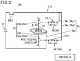
- FIG. 3 is a diagram showing a configuration example of a wire electrical discharge machine 12A according to a second embodiment of the present invention.
- the same components as those described in the first embodiment are allotted with the same reference numerals and only different parts will be described below.
- the machining circuit, designated by C1A, of the wire electrical discharge machine 12A of the second embodiment is the same as the machining circuit C1 described in the first embodiment except that a current suppression element E is disposed on each of the first current supply lines 24a and the switch SW is provided for the first current supply line 24a so as to be connected in parallel with the current suppression element E.
- the current suppression element E disposed on the first current supply line 24a1 is denoted as E1 and the current suppression element E disposed on the first current supply line 24a2 is denoted as E2. Therefore, the switch SW1 provided for the first current supply line 24a1 is connected in parallel with the current suppression element E1, whereas the switch SW2 provided for the first current supply line 24a2 is connected in parallel with the current suppression element E2.
- a resistor is illustrated as the current suppression element E, an inductor (coil) may be provided as the current suppression element E.
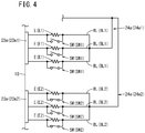
- FIG. 4 is a diagram showing a specific configuration example of first current supply lines 24a, current suppression elements E and switches SW in the second embodiment.
- the current suppression element E is disposed on at least one of the multiple current lines BL branched from the first current supply line 24a.
- the current suppression element E1 is disposed on the current line BL1 of the first current supply line 24a1 and the current suppression element E2 is disposed on the current line BL2 of the first current supply line 24a2. Therefore, the switch SW1 is provided for the current line BL1 so as to be connected in parallel with the current suppression element E1, and the switch SW2 is provided for the current line BL2 so as to be connected in parallel with the current suppression element E2.
- the switch SW and the current suppression element E are provided in each of the three branched current lines BL.
- the controller 14 performs on-off control of the switching element SWE1 and the switches SW in accordance with machining conditions to thereby perform electrical discharge machining on the workpiece W.
- the controller 14 turns on (closes) all the switches SW and performs on-off control of the switching element SWE1 to machine the workpiece W.
- the controller 14 turns off (opens) at least one of the switches SW and performs on/off control of the switching element SWE1 so as to melt part of the wire electrode 10 while machining the workpiece to thereby weld the core to the workpiece W with the molten material.
- the controller 14 Since it is necessary to suppress the machining current flowing through the electrode gap EG in the core retaining mode, the controller 14 turns off at least one of the switches SW according to the machining conditions for the retaining cycle (machining conditions for welding), so as to increase the impedance between the electrode unit 20 and the machining power source 22. That is, the impedance between the electrode unit 20 and the machining power source 22 in the retaining cycle is set higher than the impedance in the cutting cycle.
- two of the three switches SW1 are turned off and one of the three switches SW2 is turned off.
- the number and location of the switches SW (SW1, SW2) to be turned off are determined according to the machining conditions of the retaining cycle. In this way, it is possible to increase the impedance between the electrode unit 20 and the machining power source 22, more specifically, the impedance between the first electrode parts 20a and the machining power source 22, hence sufficiently suppress the machining current flowing through the electrode gap EG without lowering the set value of the machining voltage. Therefore, it is possible to firmly and sufficiently weld cores to the workpiece W with an inexpensive configuration.
- FIG. 5 is a diagram showing a configuration example of a wire electrical discharge machine 12B in Modification 1.
- Modification 1 is applied to the machining circuit C1 ( FIG. 1 ) described in the first embodiment, but it can also be applied to the machining circuit C1A ( FIG. 3 ) described in the second embodiment.
- the wire electrical discharge machine 12B of Modification 1 further includes a circuit (hereinafter, referred to as a discharge inducing circuit) C2 for applying a voltage (an inducing voltage) Vs to the electrode gap EG to induce electric discharge.
- the discharge inducing circuit C2 includes a power source (hereinafter referred to as a discharge inducing power source) 30 and a switching element SWE2 composed of an FET or the like.
- the discharge inducing power source 30 includes a DC power supply.
- the negative terminal (- terminal) of the discharge inducing power source 30 is connected to the wire electrode 10, and the positive terminal (+ terminal) is connected to the workpiece W. That is, the negative terminal of the discharge inducing power source 30 is connected to the first current supply lines 24a, and the positive terminal is connected to the second current supply line 24b.
- the discharge inducing power source 30 may be configured to selectively apply one of the positive polarity voltage Vs and the negative polarity voltage Vs to the electrode gap EG.
- the switching element SWE2 is used to apply a voltage (inducing voltage) Vs of the discharge inducing power source 30 to the electrode gap EG in order to cause electric discharge across the electrode gap EG.
- the switching element SWE2 is connected and arranged in series between the discharge inducing power source 30 and the electrode gap EG.
- the switching element SWE2 When the switching element SWE2 is turned on, the voltage Vs of the discharge inducing power source 30 is applied across the electrode gap EG. That is, as the switching element SWE2 is turned on and off, application of the voltage Vs to the electrode EG is turned on and off accordingly.
- the switching element SWE2 is provided between the negative terminal of the discharge inducing power source 30 and the wire electrode 10 (the first electrode parts 20a). However, the switching element SWE2 may be disposed between the positive terminal of the discharge inducing power source 30 and the workpiece W (the second electrode part 20b).
- the switching element SWE2 When electric discharge occurs in the electrode gap EG by application of the voltage Vs as a result of turning on the switching element SWE2, the switching element SWE2 is turned off and the switching element SWE1 is turned on so as to apply the voltage Vm across the electrode gap EG. As a result, a machining current flows through the electrode gap EG.
- the discharge inducing circuit C2 is provided, a circuit for applying the inducing voltage Vs to the electrode gap EG may be provided in the machining circuit C1, not in the discharge starting circuit C2.
- the discharge inducing circuit C2 may have a resistance r for reducing the voltage applied to the electrode gap EG. This resistance r is connected in series to the discharge inducing power source 30, the electrode gap EG, and the switching device SWE2 between the discharge inducing power source 30 and the electrode gap EG.
- FIG. 6 is a diagram showing a configuration example of a wire electrical discharge machine 12C in Modification 2.
- Modification 2 is applied to the machining circuit C1 ( FIG. 1 ) described in the first embodiment, but it can also be applied to the machining circuit C1A ( FIG. 3 ) described in the second embodiment.
- the wire electrical discharge machine 12C of Modification 2 further includes a circuit (hereinafter, referred to as a machining current freewheeling circuit) C3 for returning the machining current that has flowed through the electrode gap EG to the electrode gap EG so as to circulate the current.
- the machining current freewheeling circuit C3 is provided in the machining circuit C1.
- the machining current freewheeling circuit C3 includes a diode D and a switching element SWE3.
- the machining current freewheeling circuit C3 made up of the diode D and the switching element SWE3 connected in series is arranged in parallel with the electrode gap EG.
- the anode of the diode D is connected to the wire electrode 10 (the first electrode parts 20a), and the cathode is connected to the workpiece W (the second electrode part 20b) via the switching element SWE3.
- the anode of the diode D is connected to a point between the switching element SWE1 and the first electrode parts 20a on the first current supply line 24a.
- the switching element SWE1 When, after a machining current has flowed through the electrode gap EG by turning on the switching element SWE1, the switching element SWE1 is turned off and the switching element SWE3 is turned on from the off-state, the electric energy accumulated in the wire electrode 10 and the inductance on the machining current path flows back to the electrode gap EG through the diode D and the switching element SWE3. Therefore, while the switching element SWE3 is ON, the machining current flowing through the electrode gap EG is returned to the electrode gap EG. Accordingly, the amount (magnitude) of the machining current flowing through the electrode gap EG is maintained.
- the first electrode part 20a connected to the wire electrode 10 is provided each on the upstream side and the downstream side of the workpiece W, but the first electrode part 20a may be provided on only one of them. That is, one of the first electrode parts 20a1 and 20a2 may be omitted. In this case, one of the first current supply lines 24a1 and 24a2 becomes unnecessary correspondingly.
- the wire electrical discharge machines 12 and 12A described in the above embodiments may perform electrical discharge machining on the workpiece W which is immersed in a dielectric working fluid stored in an unillustrated work-pan, by flowing a machining current through the electrode gap EG in the working fluid.
- the switches SW (SW1, SW2) are arranged at positions not in contact with the working fluid stored in the work-pan.
- the switches SW (SW1, SW2) are provided outside the work-pan. Adopting this configuration eliminates the necessity of waterproof arrangement for preventing the working fluid from entering the switches SW (SW1, SW2), and the reliability is improved.
- switches SW are disposed on the first current supply lines 24a (See FIG. 1 ).
- a switch SW is disposed on the second current supply line 24b in order to change the impedance between the second electrode part 20b (the workpiece W) and the machining power source 22.
- the second current supply line 24b may be branched into multiple current lines BL, which are connected to the second electrode part 20b. Further, at least one of the multiple branched current lines BL may have the switch SW thereon. Also in this case, it is possible to change the impedance between the electrode unit 20 and the machining power source 22 by means of the switch SW.
- the controller 14 turns on (closes) all the switches SW and performs on-off control of the switching element SWE1 to machine the workpiece W.
- the controller 14 turns off (opens) at least one of the switches SW and performs on/off control of the switching element SWE1.
- the second current supply line 24b may be branched into multiple current lines BL, which are connected to the second electrode part 20b. Further, at least one of the multiple branched current lines BL may have the current suppression element E thereon, and a switch SW is provided for the current line BL so as to be connected in parallel with the current suppression element E. Also in this case, it is possible to change the impedance between the electrode unit 20 and the machining power source 22 by means of the switch SW.
- the controller 14 turns on (closes) all the switches SW and performs on-off control of the switching element SWE1 to machine the workpiece W.
- the controller 14 turns off (opens) at least one of the switches SW and performs on/off control of the switching element SWE1.
- the wire electrical discharge machine (12, 12A to 12C) described in each of the above-described embodiments and Modifications 1 to 5, uses a machining power source (22) to apply a machining current across an electrode gap (EG) formed between a wire electrode (10) and a workpiece (W) to be machined, and perform electrical discharge machining on the workpiece (W).
- a machining power source (22) to apply a machining current across an electrode gap (EG) formed between a wire electrode (10) and a workpiece (W) to be machined, and perform electrical discharge machining on the workpiece (W).
- the wire electrical discharge machine (12, 12A to 12C) includes: an electrode unit (20) for supplying the machining current to the electrode gap (EG); a switch (SW) for changing impedance between the machining power source (22) and the electrode unit (20); and a controller (14) for, at the time of a core retaining process, controlling the switch (SW) to set the impedance to be higher than the impedance in a cutting process, and thereby suppressing the machining current flowing through the electrode gap (EG).
- This configuration makes it possible to suppress the machining current flowing through the electrode gap (EG) during a core retaining process to a lower level with a more inexpensive manner than the prior art. Accordingly, it is possible to firmly and sufficiently weld cores to the workpiece (W).
- the electrode unit (20) may include a first electrode part (20a) connected to the wire electrode (10) and a second electrode part (20b) connected to the workpiece (W).
- the switch (SW) may be provided for a first current supply line (24a) connected to the machining power source (22) and the first electrode part (20a) in order to change the impedance between the machining power source (22) and the first electrode part (20a).
- the switch (SW) may be disposed on the first current supply line (24a). Thus, simply by providing the switch (SW), it is possible to easily change the impedance between the machining power source (22) and the first electrode part (20a).
- the first current supply line (24a) may branch into a plurality of current lines (BL) and the multiple branched current lines (BL) may be each connected to the first electrode part (20a).
- the switch (SW) is disposed on at least one of the multiple branched current lines (BL). This makes it possible to finely change the impedance between the machining power source (22) and the first electrode part (20a).
- a current suppression element (E) may be disposed on the first current supply line (24a), and the switch (SW) may be connected in parallel with the current suppression element (E). This arrangement makes it possible to easily change the impedance between the machining power source (22) and the first electrode part (20a) by merely turning on and off the switch (SW).
- the current suppression element (E) may be disposed on at least one of the multiple current lines (BL) branched from the first current supply line (24a). With this, it is possible to finely change the impedance between the machining power source (22) and the first electrode part (20a).
- the first electrode part (20a) may be provided on each of the upstream side and the downstream side of the workpiece (W) with respect to the feeding direction of the wire electrode (10).
- the switch (SW) is provided for at least one of the first current supply line (24a1) connected to the machining power source (22) and the first electrode part (20a1) provided on the upstream side, and the first current supply line (24a2) connected to the machining power source (22) and the first electrode part (20a2) provided on the downstream side.
- the wire electrical discharge machine (12, 12A to 12C) may perform electrical discharge machining on the workpiece (W) by flowing a machining current through the electrode gap (EG) in a dielectric working fluid stored in a work-pan.
- the switch (SW) may be arranged at such a position as not to come into contact with the working fluid stored in the work-pan. With this arrangement, it is possible to prevent fluid such as water from adhering to the switch (SW), and hence prevent such a situation that the switch (SW) is accidentally brought into an ON state due to leak current when the switch (SW) is turned off. Therefore, it is possible to change the impedance between the machining power source (22) and the first electrode part (20a) to a desired value.
- the switch (SW) may be provided for a second current supply line (24b) connected to the machining power source (22) and the second electrode part (20b) in order to change the impedance between the machining power source (22) and the second electrode part (20b).
- the switch (SW) may be disposed on the second current supply line (24b). Thus, simply by providing the switch (SW), it is possible to easily change the impedance between the machining power source (22) and the second electrode part (20b).
- the second current supply line (24b) may branch into a plurality of current lines (BL), and the multiple branched current lines (BL) may be each connected to the second electrode part (20b).
- the switch (SW) may be disposed on at least one of the multiple branched current lines (BL). This makes it possible to finely change the impedance between the machining power source (22) and the second electrode part (20b).
- a current suppression element (E) may be disposed on the second current supply line (24b), and the switch (SW) may be connected in parallel with the current suppression element (E). This arrangement makes it possible to simply change the impedance between the machining power source (22) and the second electrode part (20b) by merely turning on and off the switch (SW).
- the current suppression element (E) may be disposed on at least one of the multiple current lines (BL) branched from the second current supply line (24b). This makes it possible to finely change the impedance between the machining power source (22) and the second electrode part (20b).
- the wire electrical discharge machine (12B) may further include a discharge inducing circuit (C2) for applying, across the electrode gap (EG), an inducing voltage (Vs) for inducing an electrical discharge, before the machining current is supplied.
- C2 discharge inducing circuit
- Vs inducing voltage
- the wire electrical discharge machine (12C) may further include a machining current freewheeling circuit (C3) for returning the machining current flowing through the electrode gap (EG), to the electrode gap (EG) so as to circulate the machining current. Thereby, it is possible to maintain the amount (magnitude) of the machining current flowing through the electrode gap (EG).
- a machining current freewheeling circuit C3 for returning the machining current flowing through the electrode gap (EG), to the electrode gap (EG) so as to circulate the machining current.
Landscapes
- Engineering & Computer Science (AREA)
- Mechanical Engineering (AREA)
- Chemical & Material Sciences (AREA)
- Chemical Kinetics & Catalysis (AREA)
- Electrochemistry (AREA)
- Electrical Discharge Machining, Electrochemical Machining, And Combined Machining (AREA)
Abstract
Description
- The present invention relates to a wire electrical discharge machine having a core retaining function for retaining cores during machining.
- Japanese Patent No.
5651091 - However, in the above-mentioned Japanese Patent No.
5651091 - It is therefore an object of the present invention to provide a wire electrical discharge machine that can sufficiently suppress the machining current flowing through the electrode gap during a core retaining process without use of any expensive machining power supply having a wide voltage output range as described above.
- According to an aspect of the present invention, a wire electrical discharge machine using a machining power source to apply a machining current across an electrode gap formed between a wire electrode and a workpiece to be machined and thereby perform electrical discharge machining on the workpiece, includes: an electrode unit configured to supply the machining current to the electrode gap; a switch configured to change impedance between the machining power source and the electrode unit; and a controller configured to, at the time of a core retaining process, control the switch to set the impedance to be higher than the impedance in a cutting process and thereby suppress the machining current flowing through the electrode gap.
- According to the present invention, it is possible to sufficiently suppress the machining current flowing through the electrode gap during a core retaining process without using an expensive machining power source that can output a wide range of voltage. Therefore, cores can be welded to the workpiece with an inexpensive configuration.
- The above and other objects features and advantages of the present invention will become more apparent from the following description when taken in conjunction with the accompanying drawings in which a preferred embodiment of the present invention is shown by way of illustrative example.
-
-
FIG. 1 is a diagram showing a configuration example of a wire electrical discharge machine according to a first embodiment of the present invention; -
FIG. 2 is a diagram showing a specific configuration example of first current supply lines and switches shown inFIG. 1 ; -
FIG. 3 is a diagram showing a configuration example of a wire electrical discharge machine according to a second embodiment of the present embodiment; -
FIG. 4 is a diagram showing a specific configuration example of first current supply lines, current suppression elements and switches shown inFIG. 3 ; -
FIG. 5 is a diagram showing a configuration example of a wire electrical discharge machine according to Modification 1; and -
FIG. 6 is a diagram showing a configuration example of a wire electrical discharge machine according to Modification 2. - A wire electrical discharge machine according to the present invention will be detailed hereinbelow by describing preferred embodiments with reference to the accompanying drawings.
-
FIG. 1 is a diagram showing a configuration example of a wireelectrical discharge machine 12 according to a first embodiment of the present invention. The wireelectrical discharge machine 12 performs electrical discharge machining by applying voltage across an electrode gap EG formed between awire electrode 10 and an object to be machined (workpiece) W to flow a machining current (discharge current). The wireelectrical discharge machine 12 machines the workpiece W by feeding thewire electrode 10 in the Z-direction toward the workpiece W while changing the relative position between thewire electrode 10 and the workpiece W on the XY-plane orthogonal to the Z-direction. That is, thewire electrode 10 is relatively moved along a predetermined path on the workpiece W to thereby machine the workpiece W. A core is formed during this cutting process. The wireelectrical discharge machine 12 has a core retaining function for fixing the core that was formed during machining, to the workpiece W. - The wire
electrical discharge machine 12 includes a circuit (hereinafter referred to as a machining circuit) C1 for applying a voltage (machining voltage) Vm across the electrode gap EG to flow a machining current, and acontroller 14 for controlling components of the wireelectrical discharge machine 12 inclusive of the machining circuit C1. The machining circuit C1 includes anelectrode unit 20, a power source (hereinafter referred to as a machining power source) 22, a switching element SWE1, and switches SW. - The
electrode unit 20 is adapted to supply machining current to the electrode gap EG and hasfirst electrode parts 20a connected to thewire electrode 10 and asecond electrode part 20b connected to the workpiece W. Thefirst electrode parts 20a are made up of two electrode parts, one part being located on the upstream side of the workpiece W (on the upper side of the workpiece W inFIG. 1 ) while the other part being located on the downstream side of the workpiece W (on the lower side of the workpiece W inFIG. 1 ) with respect to the feeding direction of thewire electrode 10. In order to distinguish thefirst electrode parts 20a on the upstream side and the downstream side from each other, thefirst electrode part 20a located upstream of the workpiece W is referred to as 20a1 whereas thefirst electrode part 20a located downstream of the workpiece W is referred to as 20a2. - The
machining power source 22 has a DC current power supply. In the first embodiment, in order to apply the positive polarity voltage Vm to the electrode gap EG, the negative terminal (- terminal) of themachining power source 22 is connected to the wire electrode 10 (first electrode parts 20a), and the positive terminal (+ terminal) is connected to the workpiece W (thesecond electrode part 20b). It should be noted that themachining power source 22 may be configured to selectively apply one of the positive polarity voltage Vm and the negative polarity voltage Vm to the electrode gap EG. - The
electrode unit 20 and themachining power source 22 are connected bycurrent supply lines 24. Thecurrent supply lines 24 include a firstcurrent supply line 24a that connects the machining power source 22 (negative terminal) with thefirst electrode parts 20a and a secondcurrent supply line 24b that connects the machining power source 22 (positive terminal) with thesecond electrode part 20b. Here, for convenience sake, the firstcurrent supply line 24a connected to the first electrode part 20a1 located upstream of the workpiece W is called 24a1 and the firstcurrent supply line 24a connected to the first electrode part 20a2 located downstream of the workpiece W is called 24a2. - The switching element SWE1 is provided to supply machining current from the
machining power source 22 to the electrode gap EG. The switching element SWE1 is arranged between themachining power source 22 and the electrode gap EG and connected in series with themachining power source 22 and the electrode gap EG. In the first embodiment, the switching element SWE1 is arranged between themachining power source 22 and thefirst electrode part 20a (the wire electrode 10) and connected in series with themachining power source 22 and thefirst electrode part 20a (the wire electrode 10). That is, the switching element SWE1 is disposed on the firstcurrent supply line 24a. By turning on the switching element SWE1, the voltage Vm of themachining power source 22 is applied to the electrode gap EG so that a machining current flows through the electrode gap EG. That is, as the switching element SWE1 is turned on and off, application of the voltage Vm to the electrode gap EG is turned on and off accordingly. The switching element SWE1 may be a switching element such as an FET. - Note that the switching element SWE1 may be arranged between the
machining power source 22 and thesecond electrode part 20b (the workpiece W) and connected in series with themachining power source 22 and thesecond electrode part 20b (the workpiece W). That is, the switching element SWE1 may be disposed on the secondcurrent supply line 24b. Alternatively, the two switching elements SWE1 may be arranged respectively between themachining power source 22 and thefirst electrode part 20a and between themachining power source 22 and thesecond electrode part 20b. - The switches SW serve to change the impedance between the electrode unit 20 (
electrode parts machining power source 22. In order to change the impedance between thefirst electrode parts 20a and themachining power source 22, the switches SW are provided for the firstcurrent supply lines 24a (24a1, 24a2) connected between thefirst electrode parts 20a (20a1, 20a2) and themachining power source 22. The switches SW are disposed on the firstcurrent supply lines 24a (24a1, 24a2). Here, the switch SW provided for the first current supply line 24a1 is referred to as SW1, and the switch SW provided for the first current supply line 24a2 is referred to as SW2. The switch SW may be a switching element such as an FET. -
FIG. 2 is a diagram showing a specific configuration example of the firstcurrent supply lines 24a and the switches SW. Each of the firstcurrent supply lines 24a branches into a plurality of current lines BL, and the multiple branched current lines BL are each connected to thefirst electrode part 20a. At least one of current lines BL among the multiple branched current lines BL includes the switch SW. In the first embodiment, each of the firstcurrent supply lines 24a branches into three lines BL, and the switch SW is disposed on each of the lines BL. - Herein, the current lines BL branched from the first current supply line 24a1 and connected to the first electrode part 20a1 are denoted by BL1, and the current lines BL branched from the first current supply line 24a2 and connected to the first electrode part 20a2 are denoted by BL2. Thus, the switches SW1 are disposed on the current lines BL1, and the switches SW2 are disposed on the current lines BL2.
- The
controller 14 shown inFIG. 1 performs on-off control of the switching element SWE1 and the switches SW in accordance with machining conditions to thereby perform electrical discharge machining on the workpiece W. At the time of ordinary machining (cutting cycle), thecontroller 14 turns on (closes) all the switches SW and performs on-off control of the switching element SWE1 to machine the workpiece W. On the other hand, in the core retaining process (at the time of core retaining cycle), thecontroller 14 turns off (opens) at least one of the switches SW and performs on/off control of the switching element SWE1 so as to melt part of thewire electrode 10 while perform cutting to thereby weld and stick the core to the workpiece W with the melted material. - The
controller 14 performs machining by moving thewire electrode 10 along a predetermined path on the workpiece W to be machined. In principle, thecontroller 14 machines the workpiece W in accordance with the machining conditions of the cutting cycle (cutting process). In the cutting cycle, all the switches SW are set in the ON (closed) state. When thewire electrode 10 passes through predetermined points for fixing (for example, four points) on the path, thecontroller 14 changes operation from the cutting cycle to the retaining cycle (core retaining process) to thereby machine the workpiece W in accordance with the machining conditions for retaining cycle (machining conditions for welding) while fusing part of thewire electrode 10 and fixing the core to the workpiece W with the melt. As a result, the core is fixed to the workpiece W at predetermined positions along the path. In the retaining cycle, at least one of the switches SW is in the off (open) state. - Since it is necessary to suppress the machining current flowing through the electrode gap EG at the time of retaining cycle, the
controller 14 turns off at least one of the switches SW according to the machining conditions for the retaining cycle, so as to increase the impedance between theelectrode unit 20 and themachining power source 22. That is, the impedance between theelectrode unit 20 and themachining power source 22 in the retaining cycle is set higher than the impedance in the cutting cycle. - In the example shown in
FIG. 2 , two of the three switches SW1 are turned off and one of the three switches SW2 is turned off. The number and location of the switches SW (SW1, SW2) to be turned off are determined according to the machining conditions of the retaining cycle. In this way, it is possible to increase the impedance between theelectrode unit 20 and themachining power source 22, more specifically, the impedance between thefirst electrode parts 20a and themachining power source 22, hence sufficiently suppress the machining current flowing through the electrode gap EG without lowering the set value of the machining voltage. Therefore, it is possible to firmly and sufficiently weld cores to the workpiece W with an inexpensive configuration. In addition to increasing the impedance by turning off the switches SW (SW1, SW2), if the set value of the machining voltage is lowered, it is possible to produce and apply a machining current with a lower peak. In this case, the core can be welded to the workpiece W more reliably. When no machining current flows through the electrode gap EG if all the switches SW are turned off as in the case ofFIG. 2 , it never happens that all the switches SW are turned off. -
FIG. 3 is a diagram showing a configuration example of a wireelectrical discharge machine 12A according to a second embodiment of the present invention. In the second embodiment, the same components as those described in the first embodiment are allotted with the same reference numerals and only different parts will be described below. - The machining circuit, designated by C1A, of the wire
electrical discharge machine 12A of the second embodiment is the same as the machining circuit C1 described in the first embodiment except that a current suppression element E is disposed on each of the firstcurrent supply lines 24a and the switch SW is provided for the firstcurrent supply line 24a so as to be connected in parallel with the current suppression element E. The current suppression element E disposed on the first current supply line 24a1 is denoted as E1 and the current suppression element E disposed on the first current supply line 24a2 is denoted as E2. Therefore, the switch SW1 provided for the first current supply line 24a1 is connected in parallel with the current suppression element E1, whereas the switch SW2 provided for the first current supply line 24a2 is connected in parallel with the current suppression element E2. Though inFIG. 3 a resistor is illustrated as the current suppression element E, an inductor (coil) may be provided as the current suppression element E. -
FIG. 4 is a diagram showing a specific configuration example of firstcurrent supply lines 24a, current suppression elements E and switches SW in the second embodiment. The current suppression element E is disposed on at least one of the multiple current lines BL branched from the firstcurrent supply line 24a. The current suppression element E1 is disposed on the current line BL1 of the first current supply line 24a1 and the current suppression element E2 is disposed on the current line BL2 of the first current supply line 24a2. Therefore, the switch SW1 is provided for the current line BL1 so as to be connected in parallel with the current suppression element E1, and the switch SW2 is provided for the current line BL2 so as to be connected in parallel with the current suppression element E2. Also in the second embodiment, it is assumed that three branched current lines BL are provided, and the switch SW and the current suppression element E are provided in each of the three branched current lines BL. - Also in the second embodiment, the
controller 14 performs on-off control of the switching element SWE1 and the switches SW in accordance with machining conditions to thereby perform electrical discharge machining on the workpiece W. At the time of ordinary machining (cutting cycle), thecontroller 14 turns on (closes) all the switches SW and performs on-off control of the switching element SWE1 to machine the workpiece W. On the other hand, at the time of the core retaining process (retaining cycle), thecontroller 14 turns off (opens) at least one of the switches SW and performs on/off control of the switching element SWE1 so as to melt part of thewire electrode 10 while machining the workpiece to thereby weld the core to the workpiece W with the molten material. - Since it is necessary to suppress the machining current flowing through the electrode gap EG in the core retaining mode, the
controller 14 turns off at least one of the switches SW according to the machining conditions for the retaining cycle (machining conditions for welding), so as to increase the impedance between theelectrode unit 20 and themachining power source 22. That is, the impedance between theelectrode unit 20 and themachining power source 22 in the retaining cycle is set higher than the impedance in the cutting cycle. - In the example shown in
FIG. 4 , two of the three switches SW1 are turned off and one of the three switches SW2 is turned off. The number and location of the switches SW (SW1, SW2) to be turned off are determined according to the machining conditions of the retaining cycle. In this way, it is possible to increase the impedance between theelectrode unit 20 and themachining power source 22, more specifically, the impedance between thefirst electrode parts 20a and themachining power source 22, hence sufficiently suppress the machining current flowing through the electrode gap EG without lowering the set value of the machining voltage. Therefore, it is possible to firmly and sufficiently weld cores to the workpiece W with an inexpensive configuration. - Each of the above embodiments may be modified as follows. In the following modifications, the same components as those described in the above embodiments are allotted with the same reference numerals, and only different portions will be described below.
-
FIG. 5 is a diagram showing a configuration example of a wireelectrical discharge machine 12B in Modification 1. In the following description, Modification 1 is applied to the machining circuit C1 (FIG. 1 ) described in the first embodiment, but it can also be applied to the machining circuit C1A (FIG. 3 ) described in the second embodiment. - In addition to the machining circuit C1 and the
controller 14, the wireelectrical discharge machine 12B of Modification 1 further includes a circuit (hereinafter, referred to as a discharge inducing circuit) C2 for applying a voltage (an inducing voltage) Vs to the electrode gap EG to induce electric discharge. The discharge inducing circuit C2 includes a power source (hereinafter referred to as a discharge inducing power source) 30 and a switching element SWE2 composed of an FET or the like. - The discharge inducing
power source 30 includes a DC power supply. In Modification 1, in order to apply a positive polarity voltage Vs to the electrode gap EG, the negative terminal (- terminal) of the discharge inducingpower source 30 is connected to thewire electrode 10, and the positive terminal (+ terminal) is connected to the workpiece W. That is, the negative terminal of the discharge inducingpower source 30 is connected to the firstcurrent supply lines 24a, and the positive terminal is connected to the secondcurrent supply line 24b. Here, it should be noted that the discharge inducingpower source 30 may be configured to selectively apply one of the positive polarity voltage Vs and the negative polarity voltage Vs to the electrode gap EG. - The switching element SWE2 is used to apply a voltage (inducing voltage) Vs of the discharge inducing
power source 30 to the electrode gap EG in order to cause electric discharge across the electrode gap EG. The switching element SWE2 is connected and arranged in series between the discharge inducingpower source 30 and the electrode gap EG. When the switching element SWE2 is turned on, the voltage Vs of the discharge inducingpower source 30 is applied across the electrode gap EG. That is, as the switching element SWE2 is turned on and off, application of the voltage Vs to the electrode EG is turned on and off accordingly. In the example shown inFIG. 5 , the switching element SWE2 is provided between the negative terminal of the discharge inducingpower source 30 and the wire electrode 10 (thefirst electrode parts 20a). However, the switching element SWE2 may be disposed between the positive terminal of the discharge inducingpower source 30 and the workpiece W (thesecond electrode part 20b). - When electric discharge occurs in the electrode gap EG by application of the voltage Vs as a result of turning on the switching element SWE2, the switching element SWE2 is turned off and the switching element SWE1 is turned on so as to apply the voltage Vm across the electrode gap EG. As a result, a machining current flows through the electrode gap EG. Though the discharge inducing circuit C2 is provided, a circuit for applying the inducing voltage Vs to the electrode gap EG may be provided in the machining circuit C1, not in the discharge starting circuit C2.
- The discharge inducing circuit C2 may have a resistance r for reducing the voltage applied to the electrode gap EG. This resistance r is connected in series to the discharge inducing
power source 30, the electrode gap EG, and the switching device SWE2 between the discharge inducingpower source 30 and the electrode gap EG. -
FIG. 6 is a diagram showing a configuration example of a wireelectrical discharge machine 12C in Modification 2. In the following description, Modification 2 is applied to the machining circuit C1 (FIG. 1 ) described in the first embodiment, but it can also be applied to the machining circuit C1A (FIG. 3 ) described in the second embodiment. - In addition to the machining circuit C1 and the
controller 14, the wireelectrical discharge machine 12C of Modification 2 further includes a circuit (hereinafter, referred to as a machining current freewheeling circuit) C3 for returning the machining current that has flowed through the electrode gap EG to the electrode gap EG so as to circulate the current. The machining current freewheeling circuit C3 is provided in the machining circuit C1. The machining current freewheeling circuit C3 includes a diode D and a switching element SWE3. - The machining current freewheeling circuit C3 made up of the diode D and the switching element SWE3 connected in series is arranged in parallel with the electrode gap EG. In Modification 2, the anode of the diode D is connected to the wire electrode 10 (the
first electrode parts 20a), and the cathode is connected to the workpiece W (thesecond electrode part 20b) via the switching element SWE3. The anode of the diode D is connected to a point between the switching element SWE1 and thefirst electrode parts 20a on the firstcurrent supply line 24a. - When, after a machining current has flowed through the electrode gap EG by turning on the switching element SWE1, the switching element SWE1 is turned off and the switching element SWE3 is turned on from the off-state, the electric energy accumulated in the
wire electrode 10 and the inductance on the machining current path flows back to the electrode gap EG through the diode D and the switching element SWE3. Therefore, while the switching element SWE3 is ON, the machining current flowing through the electrode gap EG is returned to the electrode gap EG. Accordingly, the amount (magnitude) of the machining current flowing through the electrode gap EG is maintained. Since provision of the freewheeling diode D in this manner makes it possible to supply a low-peak machining current for a long time to the electrode gap, it is possible to further increase the amount (deposit) of molten material of thewire electrode 10 for welding the core to the workpiece W. - In each of the above-described embodiments, the
first electrode part 20a connected to thewire electrode 10 is provided each on the upstream side and the downstream side of the workpiece W, but thefirst electrode part 20a may be provided on only one of them. That is, one of the first electrode parts 20a1 and 20a2 may be omitted. In this case, one of the first current supply lines 24a1 and 24a2 becomes unnecessary correspondingly. - The wire
electrical discharge machines - In the first embodiment, in order to change the impedance between the
first electrode parts 20a (the wire electrode 10) and themachining power source 22, switches SW are disposed on the firstcurrent supply lines 24a (SeeFIG. 1 ). However, in Modification 5, a switch SW is disposed on the secondcurrent supply line 24b in order to change the impedance between thesecond electrode part 20b (the workpiece W) and themachining power source 22. - Also in this case, similarly to
FIG. 2 the secondcurrent supply line 24b may be branched into multiple current lines BL, which are connected to thesecond electrode part 20b. Further, at least one of the multiple branched current lines BL may have the switch SW thereon. Also in this case, it is possible to change the impedance between theelectrode unit 20 and themachining power source 22 by means of the switch SW. - Also in Modification 5, at the time of the cutting process (cutting cycle), the
controller 14 turns on (closes) all the switches SW and performs on-off control of the switching element SWE1 to machine the workpiece W. On the other hand, at the time of a core retaining process (retaining cycle), thecontroller 14 turns off (opens) at least one of the switches SW and performs on/off control of the switching element SWE1. By turning off at least one of the switches SW at the time of the core retaining process, it is possible to increase the impedance between theelectrode unit 20 and themachining power source 22, hence sufficiently suppress the machining current flowing through the electrode gap EG without lowering the set value of the machining voltage. Therefore, it is possible to firmly and sufficiently weld cores to the workpiece W. When no machining current flows through the electrode gap EG if all the switches SW are turned off, it never happens that all the switches SW are turned off. - In the second embodiment, in order to change the impedance between the
first electrode parts 20a (the wire electrode 10) and themachining power source 22, current suppression elements E are disposed on the firstcurrent supply lines 24a while switches SW are provided for the firstcurrent supply lines 24a so that each switch SW is connected in parallel with the associated current suppression element E (seeFIG. 3 ). However, in Modification 6, in order to change the impedance between thesecond electrode part 20b (the workpiece W) and themachining power source 22, a current suppression element E is disposed on the secondcurrent supply line 24b while a switch SW is provided in the secondcurrent supply line 24b so as to be connected in parallel with the current suppression element E. - Also in this case, similarly to
FIG. 4 the secondcurrent supply line 24b may be branched into multiple current lines BL, which are connected to thesecond electrode part 20b. Further, at least one of the multiple branched current lines BL may have the current suppression element E thereon, and a switch SW is provided for the current line BL so as to be connected in parallel with the current suppression element E. Also in this case, it is possible to change the impedance between theelectrode unit 20 and themachining power source 22 by means of the switch SW. - Also in Modification 6, at the time of the cutting process (cutting cycle), the
controller 14 turns on (closes) all the switches SW and performs on-off control of the switching element SWE1 to machine the workpiece W. On the other hand, in a core retaining process (retaining cycle), thecontroller 14 turns off (opens) at least one of the switches SW and performs on/off control of the switching element SWE1. By turning off at least one of the switches SW at the time of the core retaining process, it is possible to increase the impedance between theelectrode unit 20 and themachining power source 22, hence sufficiently suppress the machining current flowing through the electrode gap EG without lowering the set value of the machining voltage. Therefore, it is possible to firmly and reliably weld cores to the workpiece W. When no machining current flows through the electrode gap EG if all the switches SW are turned off, it never happens that all the switches SW are turned off. - It is possible to adopt any combination of the above Modifications 1 to 5. Further, any combination of the above Modifications 1 to 4 and 6 may also be adopted.
- As described above, the wire electrical discharge machine (12, 12A to 12C) described in each of the above-described embodiments and Modifications 1 to 5, uses a machining power source (22) to apply a machining current across an electrode gap (EG) formed between a wire electrode (10) and a workpiece (W) to be machined, and perform electrical discharge machining on the workpiece (W). The wire electrical discharge machine (12, 12A to 12C) includes: an electrode unit (20) for supplying the machining current to the electrode gap (EG); a switch (SW) for changing impedance between the machining power source (22) and the electrode unit (20); and a controller (14) for, at the time of a core retaining process, controlling the switch (SW) to set the impedance to be higher than the impedance in a cutting process, and thereby suppressing the machining current flowing through the electrode gap (EG).
- This configuration makes it possible to suppress the machining current flowing through the electrode gap (EG) during a core retaining process to a lower level with a more inexpensive manner than the prior art. Accordingly, it is possible to firmly and sufficiently weld cores to the workpiece (W).
- The electrode unit (20) may include a first electrode part (20a) connected to the wire electrode (10) and a second electrode part (20b) connected to the workpiece (W). The switch (SW) may be provided for a first current supply line (24a) connected to the machining power source (22) and the first electrode part (20a) in order to change the impedance between the machining power source (22) and the first electrode part (20a). With this, it is possible to sufficiently suppress the machining current flowing through the electrode gap (EG) during a core retaining process. Therefore, it is possible to firmly and sufficiently weld cores to the workpiece (W).
- The switch (SW) may be disposed on the first current supply line (24a). Thus, simply by providing the switch (SW), it is possible to easily change the impedance between the machining power source (22) and the first electrode part (20a).
- The first current supply line (24a) may branch into a plurality of current lines (BL) and the multiple branched current lines (BL) may be each connected to the first electrode part (20a). The switch (SW) is disposed on at least one of the multiple branched current lines (BL). This makes it possible to finely change the impedance between the machining power source (22) and the first electrode part (20a).
- A current suppression element (E) may be disposed on the first current supply line (24a), and the switch (SW) may be connected in parallel with the current suppression element (E). This arrangement makes it possible to easily change the impedance between the machining power source (22) and the first electrode part (20a) by merely turning on and off the switch (SW).
- The current suppression element (E) may be disposed on at least one of the multiple current lines (BL) branched from the first current supply line (24a). With this, it is possible to finely change the impedance between the machining power source (22) and the first electrode part (20a).
- The first electrode part (20a) may be provided on each of the upstream side and the downstream side of the workpiece (W) with respect to the feeding direction of the wire electrode (10). The switch (SW) is provided for at least one of the first current supply line (24a1) connected to the machining power source (22) and the first electrode part (20a1) provided on the upstream side, and the first current supply line (24a2) connected to the machining power source (22) and the first electrode part (20a2) provided on the downstream side.
- The wire electrical discharge machine (12, 12A to 12C) may perform electrical discharge machining on the workpiece (W) by flowing a machining current through the electrode gap (EG) in a dielectric working fluid stored in a work-pan. In this case, the switch (SW) may be arranged at such a position as not to come into contact with the working fluid stored in the work-pan. With this arrangement, it is possible to prevent fluid such as water from adhering to the switch (SW), and hence prevent such a situation that the switch (SW) is accidentally brought into an ON state due to leak current when the switch (SW) is turned off. Therefore, it is possible to change the impedance between the machining power source (22) and the first electrode part (20a) to a desired value.
- The switch (SW) may be provided for a second current supply line (24b) connected to the machining power source (22) and the second electrode part (20b) in order to change the impedance between the machining power source (22) and the second electrode part (20b). With this, it is possible to sufficiently suppress the machining current flowing through the electrode gap (EG) during a core retaining process. Therefore, it is possible to firmly and sufficiently weld cores to the workpiece (W).
- The switch (SW) may be disposed on the second current supply line (24b). Thus, simply by providing the switch (SW), it is possible to easily change the impedance between the machining power source (22) and the second electrode part (20b).
- The second current supply line (24b) may branch into a plurality of current lines (BL), and the multiple branched current lines (BL) may be each connected to the second electrode part (20b). The switch (SW) may be disposed on at least one of the multiple branched current lines (BL). This makes it possible to finely change the impedance between the machining power source (22) and the second electrode part (20b).
- A current suppression element (E) may be disposed on the second current supply line (24b), and the switch (SW) may be connected in parallel with the current suppression element (E). This arrangement makes it possible to simply change the impedance between the machining power source (22) and the second electrode part (20b) by merely turning on and off the switch (SW).
- The current suppression element (E) may be disposed on at least one of the multiple current lines (BL) branched from the second current supply line (24b). This makes it possible to finely change the impedance between the machining power source (22) and the second electrode part (20b).
- The wire electrical discharge machine (12B) may further include a discharge inducing circuit (C2) for applying, across the electrode gap (EG), an inducing voltage (Vs) for inducing an electrical discharge, before the machining current is supplied.
- The wire electrical discharge machine (12C) may further include a machining current freewheeling circuit (C3) for returning the machining current flowing through the electrode gap (EG), to the electrode gap (EG) so as to circulate the machining current. Thereby, it is possible to maintain the amount (magnitude) of the machining current flowing through the electrode gap (EG).
Claims (15)
- A wire electrical discharge machine (12, 12A to 12C) using a machining power source (22) to apply a machining current across an electrode gap (EG) formed between a wire electrode (10) and a workpiece (W) to be machined and thereby perform electrical discharge machining on the workpiece (W), comprising:an electrode unit (20) configured to supply the machining current to the electrode gap (EG);a switch (SW) configured to change impedance between the machining power source (22) and the electrode unit (20); anda controller (14) configured to, at a time of a core retaining process, control the switch (SW) to set the impedance to be higher than the impedance in a cutting process and thereby suppress the machining current flowing through the electrode gap (EG).
- The wire electrical discharge machine (12, 12A to 12C) according to claim 1, wherein:the electrode unit (20) includes a first electrode part (20a) connected to the wire electrode (10) and a second electrode part (20b) connected to the workpiece (W); andthe switch (SW) is provided for a first current supply line (24a) connected to the machining power source (22) and the first electrode part (20a) in order to change the impedance between the machining power source (22) and the first electrode part (20a).
- The wire electrical discharge machine (12, 12B to 12C) according to claim 2, wherein the switch (SW) is disposed on the first current supply line (24a).
- The wire electrical discharge machine (12, 12B to 12C) according to claim 3, wherein:the first current supply line (24a) branches into a plurality of current lines (BL);the plurality of branched current lines (BL) are each connected to the first electrode part (20a); andthe switch (SW) is disposed on at least one of the plurality of branched current lines (BL).
- The wire electrical discharge machine (12A to 12C) according to claim 2, further comprising a current suppression element (E) disposed on the first current supply line (24a), wherein the switch (SW) is connected in parallel with the current suppression element (E).
- The wire electrical discharge machine (12A to 12C) according to claim 5, wherein:the first current supply line (24a) branches into a plurality of current lines (BL);the plurality of branched current lines (BL) are each connected to the first electrode part (20a); andthe current suppression element (E) is disposed on at least one of the plurality of branched current lines (BL).
- The wire electrical discharge machine (12, 12A to 12C) according to any one of claims 2 to 6, wherein:the first electrode part (20a) is provided on each of an upstream side and a downstream side of the workpiece (W) with respect to a feeding direction of the wire electrode (10); andthe switch (SW) is provided for at least one of the first current supply line (24a1) connected to the machining power source (22) and the first electrode part (20a1) provided on the upstream side, and the first current supply line (24a2) connected to the machining power source (22) and the first electrode part (20a2) provided on the downstream side.
- The wire electrical discharge machine (12, 12A to 12C) according to any one of claims 1 to 7, wherein the wire electrical discharge machine (12, 12A to 12C) performs electrical discharge machining on the workpiece (W) by flowing a machining current through the electrode gap (EG) in a dielectric working fluid stored in a work-pan; and
the switch (SW) is arranged at a position not in contact with the dielectric working fluid stored in the work-pan. - The wire electrical discharge machine (12, 12A to 12C) according to claim 1, wherein:the electrode unit (20) includes a first electrode part (20a) connected to the wire electrode (10) and a second electrode part (20b) connected to the workpiece (W); andthe switch (SW) is provided for a second current supply line (24b) connected to the machining power source (22) and the second electrode part (20b) in order to change the impedance between the machining power source (22) and the second electrode part (20b).
- The wire electrical discharge machine (12, 12B to 12C) according to claim 9, wherein the switch (SW) is disposed on the second current supply line (24b).
- The wire electrical discharge machine (12, 12B to 12C) according to claim 10, wherein:the second current supply line (24b) branches into a plurality of current lines (BL);the plurality of branched current lines (BL) are each connected to the second electrode part (20b); andthe switch (SW) is disposed on at least one of the plurality of branched current lines (BL).
- The wire electrical discharge machine (12A to 12C) according to claim 9, further comprising a current suppression element (E) disposed on the second current supply line (24b), wherein the switch (SW) is connected in parallel with the current suppression element (E).
- The wire electrical discharge machine (12A to 12C) according to claim 12, wherein:the second current supply line (24b) branches into a plurality of current lines (BL);the plurality of branched current lines (BL) are each connected to the second electrode part (20b); andthe current suppression element (E) is disposed on at least one of the plurality of branched current lines (BL).
- The wire electrical discharge machine (12B) according to any one of claims 1 to 13, further comprising a discharge inducing circuit (C2) configured to apply an inducing voltage (Vs) for inducing an electric discharge, across the electrode gap (EG) before the machining current is supplied.
- The wire electrical discharge machine (12C) according to any one of claims 1 to 14, further comprising a machining current freewheeling circuit (C3) configured to return the machining current flowing through the electrode gap (EG), to the electrode gap (EG) so as to circulate the machining current.
Applications Claiming Priority (1)
| Application Number | Priority Date | Filing Date | Title |
|---|---|---|---|
| JP2017015160A JP6360212B1 (en) | 2017-01-31 | 2017-01-31 | Wire electric discharge machine |
Publications (2)
| Publication Number | Publication Date |
|---|---|
| EP3354390A1 true EP3354390A1 (en) | 2018-08-01 |
| EP3354390B1 EP3354390B1 (en) | 2023-01-04 |
Family
ID=61094262
Family Applications (1)
| Application Number | Title | Priority Date | Filing Date |
|---|---|---|---|
| EP18154015.4A Active EP3354390B1 (en) | 2017-01-31 | 2018-01-30 | Wire electrical discharge machine and wire electrical discharge machining method |
Country Status (6)
| Country | Link |
|---|---|
| US (1) | US10639735B2 (en) |
| EP (1) | EP3354390B1 (en) |
| JP (1) | JP6360212B1 (en) |
| KR (2) | KR20190096884A (en) |
| CN (2) | CN108372336A (en) |
| TW (1) | TWI647040B (en) |
Cited By (1)
| Publication number | Priority date | Publication date | Assignee | Title |
|---|---|---|---|---|
| TWI839195B (en) * | 2023-04-27 | 2024-04-11 | 精呈科技股份有限公司 | Electrical waveform modulation method for wire cutting rough machining |
Citations (5)
| Publication number | Priority date | Publication date | Assignee | Title |
|---|---|---|---|---|
| JPS5651091B2 (en) | 1972-05-09 | 1981-12-03 | ||
| US20090314747A1 (en) * | 2006-10-24 | 2009-12-24 | Mitsubishi Electric Corporation | Wire electric discharge machine |
| US20130277335A1 (en) * | 2012-04-24 | 2013-10-24 | Fanuc Corporation | Contact detection apparatus for wire electrical discharge machne with capability to vary applied gap voltage |
| US20140374385A1 (en) * | 2012-06-13 | 2014-12-25 | SEIBU Electric & Machinery Cp., Ltd. | Method of making partially welded spots in wire-cut electrical discharge machining |
| US20160001385A1 (en) * | 2014-07-04 | 2016-01-07 | Fanuc Corporation | Wire electric discharge machine |
Family Cites Families (135)
| Publication number | Priority date | Publication date | Assignee | Title |
|---|---|---|---|---|
| CH629411A5 (en) * | 1979-06-21 | 1982-04-30 | Charmilles Sa Ateliers | EROSIVE SPARKING MACHINE. |
| CH633471A5 (en) * | 1980-01-08 | 1982-12-15 | Charmilles Sa Ateliers | MACHINE FOR MACHINING BY EROSIVE SPARKING. |
| US4652716A (en) * | 1980-03-24 | 1987-03-24 | Charmilles Technologies, S.A. | Process and mechanism for threading the electrode wire of an EDM apparatus |
| JPS5766824A (en) * | 1980-10-08 | 1982-04-23 | Fanuc Ltd | Tapered processing method in wire cutting discharge processing machine |
| CH646894A5 (en) * | 1982-04-22 | 1984-12-28 | Charmilles Sa Ateliers | METHOD AND DEVICE FOR CUTTING BY EROSIVE DISCHARGES. |
| DE3317826C2 (en) * | 1982-05-19 | 1994-04-07 | Amada Co | Cutting wire spark erosion machine |
| JPS58211829A (en) * | 1982-06-03 | 1983-12-09 | Inoue Japax Res Inc | Wire cut electric machining device |
| JPS6244319A (en) * | 1985-08-21 | 1987-02-26 | Fanuc Ltd | Automatic wire connector for wire-cut electric discharge machine |
| DE3738251C2 (en) * | 1986-11-17 | 1994-09-22 | Inst Tech Precision Eng | Spark erosive wire cutting machine |
| JPH01140924A (en) * | 1987-11-26 | 1989-06-02 | Fanuc Ltd | Automatic method for wire connection |
| JP2522685B2 (en) * | 1988-02-03 | 1996-08-07 | ファナック株式会社 | Wire cut gap voltage detector |
| JP2573514B2 (en) * | 1988-05-11 | 1997-01-22 | ファナック株式会社 | Wire break position detection device |
| KR930004834B1 (en) * | 1988-05-18 | 1993-06-09 | 미쯔비시덴끼 가부시끼가이샤 | Wire electrode supply device of wire cut electric discharge processing equipment |
| JP2637473B2 (en) * | 1988-06-03 | 1997-08-06 | 日立精工株式会社 | Wire electric discharge machine |
| JP2812492B2 (en) * | 1988-06-21 | 1998-10-22 | 株式会社アマダワシノ | Method and apparatus for confirming that a wire electrode has passed through a wire guide portion on a wire discharge side in a wire cut electric discharge machine |
| US4894504A (en) * | 1988-06-30 | 1990-01-16 | T-Star Industrial Electronics Corporation | Method apparatus for generating multiple sparks for an electrical discharge wire cutting machine |
| JP2644543B2 (en) * | 1988-08-16 | 1997-08-25 | 株式会社アマダ | Connection method of wire electric discharge machine |
| JPH0253529A (en) * | 1988-08-16 | 1990-02-22 | Mitsubishi Electric Corp | Wire electrode supply device for wire electric discharge machine |
| CH677744A5 (en) * | 1988-08-19 | 1991-06-28 | Mitsubishi Electric Corp | |
| JPH0692047B2 (en) * | 1988-10-05 | 1994-11-16 | ブラザー工業株式会社 | Wire EDM machine taper machine |
| JPH02139127A (en) * | 1988-11-15 | 1990-05-29 | Mitsubishi Electric Corp | Wire-cut electro-discharge machining unit |
| JP2686796B2 (en) * | 1988-11-28 | 1997-12-08 | 西部電機株式会社 | Automatic wire feeding method for wire electric discharge machine |
| CH680502A5 (en) * | 1988-12-23 | 1992-09-15 | Mitsubishi Electric Corp | |
| US5149931A (en) * | 1989-04-11 | 1992-09-22 | Mitsubishi Denki K.K. | Power source for electric discharge machining |
| JP2518075B2 (en) * | 1989-04-28 | 1996-07-24 | 三菱電機株式会社 | Wire electrode supply device for wire electric discharge machine |
| DE3916190A1 (en) * | 1989-05-18 | 1990-11-22 | Mitsubishi Electric Corp | WIRE ELECTRODE FEEDER IN A MACHINE WORKING WITH MACHINING WIRE ELECTRODE AND ELECTRIC DISCHARGE |
| JPH0326421A (en) * | 1989-06-24 | 1991-02-05 | Amada Washino Co Ltd | Wire cut electric discharge machine |
| JP2734145B2 (en) * | 1989-12-15 | 1998-03-30 | 三菱電機株式会社 | Wire electric discharge machine |
| DE4107910A1 (en) | 1991-03-12 | 1992-09-17 | Agie Ag Ind Elektronik | PULSE GENERATOR FOR EDM PROCESSING AND PROCEDURE SUITABLE FOR THIS |
| DE4116868C2 (en) * | 1991-05-23 | 1995-07-27 | Agie Ag Ind Elektronik | Process for machining workpieces, in particular for EDM machining of workpieces using a wire |
| JP2722867B2 (en) * | 1991-07-01 | 1998-03-09 | 三菱電機株式会社 | Wire electric discharge machine |
| JP3084879B2 (en) * | 1992-01-27 | 2000-09-04 | ブラザー工業株式会社 | Wire electric discharge machine |
| JP3084880B2 (en) * | 1992-01-27 | 2000-09-04 | ブラザー工業株式会社 | Wire electrode cutting device in wire electric discharge machine |
| JP3237895B2 (en) * | 1992-04-30 | 2001-12-10 | ブラザー工業株式会社 | Wire electric discharge machine |
| JP3258368B2 (en) * | 1992-05-01 | 2002-02-18 | ブラザー工業株式会社 | Wire electric discharge machine |
| DE4228329C2 (en) * | 1992-08-26 | 1996-08-22 | Agie Ag Ind Elektronik | Device and method for guiding the wire electrode during EDM cutting |
| JP2914104B2 (en) * | 1993-06-30 | 1999-06-28 | 三菱電機株式会社 | Electric discharge machining method and apparatus, and variable electrostatic capacity and variable inductance applicable to this electric discharge machine |
| JP3266702B2 (en) * | 1993-07-20 | 2002-03-18 | ブラザー工業株式会社 | Wire electric discharge machine |
| JP3223723B2 (en) * | 1994-09-20 | 2001-10-29 | 三菱電機株式会社 | Wire electric discharge machine and its control method |
| JPH08243846A (en) * | 1995-03-06 | 1996-09-24 | Mitsubishi Electric Corp | Wire electric discharge machining apparatus and method |
| JP3330780B2 (en) * | 1995-05-11 | 2002-09-30 | ファナック株式会社 | Disconnection repair device in wire electric discharge machine |
| US5603851A (en) * | 1995-08-14 | 1997-02-18 | Seibu Electric & Machinery Co., Ltd. | Wire cutting electrical discharge machine with wire annealing for threading |
| JP3366509B2 (en) * | 1995-08-23 | 2003-01-14 | ファナック株式会社 | Wire electric discharge machining method |
| JPH0994720A (en) * | 1995-09-29 | 1997-04-08 | Sodick Co Ltd | Wire cut electric discharge machining device |
| EP0916440B1 (en) * | 1997-03-07 | 2006-05-10 | Sodick Co., Ltd. | System and method for wire cut discharge machining |
| CA2267621C (en) * | 1997-07-30 | 2007-10-16 | Ki Chul Seong | Method of manufacturing porous electrode wire for electric discharge machining and structure of the electrode wire |
| DE19753812C2 (en) * | 1997-12-04 | 2000-05-18 | Agie Sa | Method and device for electrical discharge machining |
| EP0934791B1 (en) * | 1998-02-05 | 2008-04-02 | Fanuc Ltd | Controller of wire electric discharge machine |
| CN1102473C (en) * | 1998-10-16 | 2003-03-05 | 三菱电机株式会社 | Wire electric discharge machine |
| CN1137796C (en) * | 1999-08-20 | 2004-02-11 | 三菱电机株式会社 | Wire cutting processing device |
| US20010007319A1 (en) * | 1999-10-05 | 2001-07-12 | Toshio Moro | Wire electrical discharge apparatus |
| JP2001277049A (en) * | 2000-03-30 | 2001-10-09 | Brother Ind Ltd | Wire electric discharge machine |
| CN1238146C (en) * | 2000-05-26 | 2006-01-25 | 三菱电机株式会社 | Apparatus for electrodischarge machining |
| JP4140174B2 (en) * | 2000-06-28 | 2008-08-27 | ブラザー工業株式会社 | Control device and control method of wire electric discharge machine, and storage medium |
| US6403911B1 (en) * | 2000-09-22 | 2002-06-11 | Industrial Technology Research Institute | Method and apparatus for the wire cut electric discharge machine |
| JP3815436B2 (en) * | 2000-09-28 | 2006-08-30 | 三菱電機株式会社 | Wire electrical discharge machine |
| CN1260030C (en) * | 2000-10-20 | 2006-06-21 | 三菱电机株式会社 | Wire EDM |
| US6744002B1 (en) * | 2000-11-20 | 2004-06-01 | Mitsubishi Denki Kabushiki Kaisha | Method and apparatus for electrodischarge wire machining |
| EP1219373B1 (en) * | 2000-12-25 | 2011-06-15 | Fanuc Corporation | Controller for wire electric discharge machine |
| US6787727B2 (en) * | 2001-01-16 | 2004-09-07 | Mitsubishi Denki Kabushiki Kaisha | Automatic wire electrode feeder for wire electric discharge machining devices |
| US7038158B2 (en) * | 2002-08-30 | 2006-05-02 | Mitsubishi Denki Kabushiki Kaisha | Wire electrical discharge machining apparatus |
| JP3808444B2 (en) * | 2003-03-24 | 2006-08-09 | ファナック株式会社 | Control device for wire electric discharge machine |
| JP3950844B2 (en) * | 2003-12-01 | 2007-08-01 | ファナック株式会社 | Electric discharge machine |
| US6998562B2 (en) * | 2004-06-02 | 2006-02-14 | Fanuc Ltd | Controller for a wire electrical discharge machine |
| JP4047849B2 (en) * | 2004-09-29 | 2008-02-13 | ファナック株式会社 | Wire-cut electric discharge machine with electronic communication to supply electric power for electric discharge machining |
| JP2006110654A (en) * | 2004-10-13 | 2006-04-27 | Sodick Co Ltd | Automatic connection device |
| JP4015148B2 (en) * | 2004-10-28 | 2007-11-28 | ファナック株式会社 | Control device for wire electric discharge machine |
| EP1749608B1 (en) * | 2005-08-01 | 2010-10-06 | Agie Charmilles SA | Method and generator for electrical discharge machining |
| EP1749606B1 (en) * | 2005-08-01 | 2013-03-13 | Agie Charmilles SA | Method and generator for electrical discharge machining |
| CN100577336C (en) * | 2005-09-15 | 2010-01-06 | 三菱电机株式会社 | Wire discharge machining device and wire discharge machining method |
| JP4097670B2 (en) * | 2006-01-05 | 2008-06-11 | ファナック株式会社 | Monitor device for machine tools |
| JP2007268631A (en) * | 2006-03-30 | 2007-10-18 | Fanuc Ltd | Wire electrode supply device of wire cut electric discharge machine |
| JP2008055539A (en) * | 2006-08-30 | 2008-03-13 | Fanuc Ltd | Wire electrode supply device for wire cut electric discharge machine |
| US7928337B2 (en) * | 2006-10-24 | 2011-04-19 | Mitsubishi Electric Corporation | Apparatus for machining a workpiece using wire discharge including an upper and lower power supply unit |
| CN101528399B (en) * | 2006-10-24 | 2011-11-09 | 三菱电机株式会社 | Wire discharge processing apparatus |
| WO2008050403A1 (en) * | 2006-10-24 | 2008-05-02 | Mitsubishi Electric Corporation | Wire discharge processing apparatus |
| US20100199909A1 (en) * | 2007-01-25 | 2010-08-12 | University Of Utah Research Foundation | Systems and methods for recycling semiconductor material removed from a raw semiconductor boule |
| WO2008092135A2 (en) * | 2007-01-25 | 2008-07-31 | University Of Utah Research Foundation | Multi-wire electron discharge machine |
| JP4168076B2 (en) * | 2007-03-08 | 2008-10-22 | ファナック株式会社 | Wire cut electric discharge machine with wire electrode tension control function |
| US20080277383A1 (en) * | 2007-05-11 | 2008-11-13 | Michael Sandlin | Apparatus for removing debris from the cutting gap of a work piece on a wire electronic discharge machine and method therefor |
| US20090101627A1 (en) * | 2007-10-18 | 2009-04-23 | Fanuc Ltd | Electric discharge machine having wire electrode cutting function, and wire electrode cutting method |
| DE112008003658B4 (en) * | 2008-01-31 | 2015-12-10 | Mitsubishi Electric Corp. | Electric discharge machining device |
| US7973260B2 (en) * | 2008-02-01 | 2011-07-05 | Industrial Technology Research Institute | Wire electrical discharge machining |
| TWI357841B (en) * | 2008-08-14 | 2012-02-11 | Ind Tech Res Inst | Method and apparatus for feed control of wire cutt |
| JP4925481B2 (en) * | 2009-07-01 | 2012-04-25 | 株式会社ソディック | Wire cut electric discharge machine |
| JP5048108B2 (en) * | 2010-08-06 | 2012-10-17 | ファナック株式会社 | Wire-cut EDM with workpiece measurement function |
| JP5073797B2 (en) * | 2010-08-26 | 2012-11-14 | ファナック株式会社 | Wire electrical discharge machine to detect machining status |
| JP5088975B2 (en) * | 2010-10-19 | 2012-12-05 | 株式会社ソディック | Wire electrical discharge machine |
| TW201223670A (en) * | 2010-12-03 | 2012-06-16 | Metal Ind Res & Dev Ct | Compound electrical discharge machining device and hole electro-discharge machining module thereof |
| JP5651091B2 (en) | 2011-01-28 | 2015-01-07 | 西部電機株式会社 | Uncut workpiece machining method in wire electrical discharge machining |
| JP4938137B1 (en) * | 2011-03-03 | 2012-05-23 | ファナック株式会社 | Wire-cut electric discharge machine with a function to detect the upper surface of the workpiece |
| JP5155424B2 (en) * | 2011-05-30 | 2013-03-06 | ファナック株式会社 | Wire-cut electrical discharge machine with wire electrode cutting function |
| CN103596717B (en) * | 2011-06-06 | 2016-11-02 | 三菱电机株式会社 | High intensity light source |
| DE112011105416T8 (en) * | 2011-07-06 | 2014-06-18 | Mitsubishi Electric Corporation | Electric wire EDM processing device |
| CN103958103B (en) * | 2011-11-30 | 2016-12-28 | 三菱电机株式会社 | Electric discharge machine supply unit |
| JP5220179B2 (en) * | 2011-12-09 | 2013-06-26 | 株式会社ソディック | Wire electric discharge machine |
| JP5266401B2 (en) * | 2012-01-20 | 2013-08-21 | ファナック株式会社 | Wire electrical discharge machine that performs electrical discharge machining by inclining wire electrodes |
| WO2013111323A1 (en) * | 2012-01-27 | 2013-08-01 | 三菱電機株式会社 | Wire discharge processing machine and wire electrode elimination device |
| DE112012005754B4 (en) * | 2012-01-27 | 2023-06-07 | Mitsubishi Electric Corporation | Wire discharge machining device and electrode wire removing device |
| JP5204321B1 (en) * | 2012-02-01 | 2013-06-05 | ファナック株式会社 | Wire electrical discharge machine that detects the machining state and calculates the average voltage between the electrodes |
| JP5270772B1 (en) * | 2012-02-15 | 2013-08-21 | ファナック株式会社 | Wire electrical discharge machine for straightening |
| JP5369205B2 (en) * | 2012-02-27 | 2013-12-18 | ファナック株式会社 | Wire electric discharge machine and wire electric discharge machining method for reducing machining flaws at the time of cutting and escaping |
| JP2013187201A (en) * | 2012-03-05 | 2013-09-19 | Asahi Kasei Electronics Co Ltd | Semiconductor device and method for manufacturing the same |
| JP5276731B1 (en) * | 2012-03-21 | 2013-08-28 | ファナック株式会社 | Wire electric discharge machine with wire electrode cutting mechanism |
| US20150053650A1 (en) * | 2012-04-12 | 2015-02-26 | Mitsubishi Electric Corporation | Wire discharge machining apparatus and manufacturing method for semiconductor wafers using the same |
| US9751157B2 (en) * | 2012-04-18 | 2017-09-05 | Seibu Electric & Machinery Co., Ltd. | Process for identifying existence of partially welded spots and retention of cut-out part in wire-cut electrical discharge machining |
| JP5569562B2 (en) * | 2012-06-20 | 2014-08-13 | キヤノンマーケティングジャパン株式会社 | Wire electric discharge machining apparatus and wire electric discharge machining method |
| CN103620089B (en) * | 2012-06-26 | 2015-12-23 | 三菱电机株式会社 | Apparatus for discharge surface treatment and discharge surface treating method |
| JP5426733B2 (en) * | 2012-07-10 | 2014-02-26 | ファナック株式会社 | Wire electric discharge machine and automatic programming device for wire electric discharge machine |
| JP5389994B1 (en) * | 2012-08-08 | 2014-01-15 | 株式会社ソディック | Electric discharge machine |
| US20150290733A1 (en) * | 2012-10-30 | 2015-10-15 | Mitsubishi Electric Corporation | Wire electrical discharge machining apparatus, machining control device, and machining control program |
| CN104066540B (en) * | 2012-10-30 | 2016-04-20 | 三菱电机株式会社 | Electric discharge device |
| CN104755214B (en) * | 2012-10-30 | 2016-08-31 | 三菱电机株式会社 | Wire discharge processing apparatus |
| JP5323285B1 (en) * | 2012-10-30 | 2013-10-23 | 三菱電機株式会社 | Wire electrical discharge machine |
| JP5657715B2 (en) * | 2013-01-11 | 2015-01-21 | ファナック株式会社 | Wire electrical discharge machine with wire electrode position correction function |
| JP5661840B2 (en) * | 2013-03-19 | 2015-01-28 | ファナック株式会社 | Wire electric discharge machine having a function of discriminating the state in a processing tank |
| JP2014200864A (en) * | 2013-04-02 | 2014-10-27 | ファナック株式会社 | Wire electric discharge machine having wire electrode tension control function |
| CN104245202B (en) * | 2013-04-12 | 2016-06-22 | 三菱电机株式会社 | Line electrode suction device and line electrode retracting device |
| JP5739563B2 (en) * | 2013-07-24 | 2015-06-24 | ファナック株式会社 | Wire electric discharge machine equipped with means for calculating average discharge delay time |
| ES2657606T3 (en) * | 2013-09-12 | 2018-03-06 | Agie Charmilles Sa | Method and apparatus for one-part EDM machining |
| JP5788468B2 (en) * | 2013-11-28 | 2015-09-30 | ファナック株式会社 | Wire electrical discharge machine with function to suppress wear of drive parts |
| US9878385B2 (en) * | 2013-12-19 | 2018-01-30 | Mitsubishi Electric Corporation | Wire electric discharge machining apparatus, wire electric discharge machining method, and control device |
| JP2015136768A (en) * | 2014-01-23 | 2015-07-30 | ファナック株式会社 | Working fluid supply control device for wire electric discharge machine |
| DE112014006529B4 (en) * | 2014-03-28 | 2020-07-02 | Mitsubishi Electric Corporation | Wire electric discharge machine |
| JP6219785B2 (en) * | 2014-06-23 | 2017-10-25 | ファナック株式会社 | Wire electric discharge machine equipped with disconnection repair means |
| JP5783653B1 (en) * | 2014-07-25 | 2015-09-24 | 株式会社ソディック | Wire cut electric discharge machine |
| JP5977294B2 (en) * | 2014-08-11 | 2016-08-24 | ファナック株式会社 | Wire EDM machine that discriminates whether EDM is possible |
| JP6235531B2 (en) * | 2014-08-11 | 2017-11-22 | ファナック株式会社 | Wire electric discharge machine with a function to move from an arbitrary retreat position in an electric discharge state and return to an interruption position |
| JP6325392B2 (en) * | 2014-08-12 | 2018-05-16 | ファナック株式会社 | Wire electrical discharge machine capable of starting machining from short circuit |
| US9873151B2 (en) * | 2014-09-26 | 2018-01-23 | Crucible Intellectual Property, Llc | Horizontal skull melt shot sleeve |
| EP3023186A1 (en) * | 2014-11-19 | 2016-05-25 | Fanuc Corporation | Wire electric discharge machine having corner shape correcting function |
| JP6169557B2 (en) * | 2014-12-26 | 2017-07-26 | ファナック株式会社 | Wire electrical discharge machine with tension monitoring function |
| JP6169635B2 (en) | 2015-03-12 | 2017-07-26 | ファナック株式会社 | Wire electrical discharge machine with the function of collecting processed products (core) |
| EP3251778B1 (en) * | 2015-04-02 | 2022-02-09 | Fanuc Corporation | Wire electric discharge machine |
| JP2018024025A (en) * | 2016-08-08 | 2018-02-15 | ファナック株式会社 | Electric discharge machine |
-
2017
- 2017-01-31 JP JP2017015160A patent/JP6360212B1/en active Active
-
2018
- 2018-01-25 US US15/879,531 patent/US10639735B2/en active Active
- 2018-01-25 TW TW107102614A patent/TWI647040B/en active
- 2018-01-30 CN CN201810092184.7A patent/CN108372336A/en active Pending
- 2018-01-30 EP EP18154015.4A patent/EP3354390B1/en active Active
- 2018-01-30 CN CN202310014502.9A patent/CN115945751A/en active Pending
-
2019
- 2019-08-02 KR KR1020190094506A patent/KR20190096884A/en not_active Ceased
-
2020
- 2020-06-22 KR KR1020200075911A patent/KR20200078445A/en not_active Ceased
Patent Citations (5)
| Publication number | Priority date | Publication date | Assignee | Title |
|---|---|---|---|---|
| JPS5651091B2 (en) | 1972-05-09 | 1981-12-03 | ||
| US20090314747A1 (en) * | 2006-10-24 | 2009-12-24 | Mitsubishi Electric Corporation | Wire electric discharge machine |
| US20130277335A1 (en) * | 2012-04-24 | 2013-10-24 | Fanuc Corporation | Contact detection apparatus for wire electrical discharge machne with capability to vary applied gap voltage |
| US20140374385A1 (en) * | 2012-06-13 | 2014-12-25 | SEIBU Electric & Machinery Cp., Ltd. | Method of making partially welded spots in wire-cut electrical discharge machining |
| US20160001385A1 (en) * | 2014-07-04 | 2016-01-07 | Fanuc Corporation | Wire electric discharge machine |
Cited By (1)
| Publication number | Priority date | Publication date | Assignee | Title |
|---|---|---|---|---|
| TWI839195B (en) * | 2023-04-27 | 2024-04-11 | 精呈科技股份有限公司 | Electrical waveform modulation method for wire cutting rough machining |
Also Published As
| Publication number | Publication date |
|---|---|
| EP3354390B1 (en) | 2023-01-04 |
| TW201832854A (en) | 2018-09-16 |
| CN115945751A (en) | 2023-04-11 |
| KR20200078445A (en) | 2020-07-01 |
| JP2018122377A (en) | 2018-08-09 |
| US10639735B2 (en) | 2020-05-05 |
| JP6360212B1 (en) | 2018-07-18 |
| TWI647040B (en) | 2019-01-11 |
| US20180214962A1 (en) | 2018-08-02 |
| CN108372336A (en) | 2018-08-07 |
| KR20190096884A (en) | 2019-08-20 |
Similar Documents
| Publication | Publication Date | Title |
|---|---|---|
| KR101569195B1 (en) | DC circuit breaker using magnetic field | |
| JP2949665B2 (en) | Plasma apparatus and operation method thereof | |
| JP2015530252A (en) | System and method for providing a controlled AC arc welding process | |
| CN104010758A (en) | High-current transformer with multipoint contact, transformer element, contact plate and secondary winding, and method for manufacturing such a high-current transformer | |
| EP3354390B1 (en) | Wire electrical discharge machine and wire electrical discharge machining method | |
| US7148442B2 (en) | Power supply device for electric discharge machining | |
| US10903643B2 (en) | Semiconductor current cutoff device including a semiconductor switch and a mechanical switch | |
| JP5565883B2 (en) | Load balance circuit, power supply device, and load balance control method | |
| WO2018131307A1 (en) | Arc-suppressing device | |
| EP3351330B1 (en) | Wire electrical discharge machine and machining method | |
| US8093526B2 (en) | Wire electric discharge machine with impedance switching | |
| JP2006043764A (en) | Consumable electrode arc welding source | |
| JP4921481B2 (en) | Wire electrical discharge machine | |
| KR101580072B1 (en) | Capacitive welder and method for charging same | |
| CN217486176U (en) | Protection circuit of alternating current relay | |
| JPH02133808A (en) | Rush current preventing circuit | |
| JPS62152618A (en) | Wire electric discharge machine | |
| JPS611473A (en) | Electric power source circuit of plasma cutting and welding device | |
| JPH03210969A (en) | Hot wire tig welding equipment | |
| JP7506312B2 (en) | How to select a capacitor for a switch | |
| KR100539069B1 (en) | Apparatus for saving consumption of electric power | |
| JPS643584Y2 (en) | ||
| JP4704590B2 (en) | Plating current supply power supply | |
| JP2024111504A (en) | Charging control device, power conversion system and control method | |
| EP0724925A2 (en) | Power supply apparatus for an electric discharge machine |
Legal Events
| Date | Code | Title | Description |
|---|---|---|---|
| PUAI | Public reference made under article 153(3) epc to a published international application that has entered the european phase |
Free format text: ORIGINAL CODE: 0009012 |
|
| STAA | Information on the status of an ep patent application or granted ep patent |
Free format text: STATUS: THE APPLICATION HAS BEEN PUBLISHED |
|
| AK | Designated contracting states |
Kind code of ref document: A1 Designated state(s): AL AT BE BG CH CY CZ DE DK EE ES FI FR GB GR HR HU IE IS IT LI LT LU LV MC MK MT NL NO PL PT RO RS SE SI SK SM TR |
|
| AX | Request for extension of the european patent |
Extension state: BA ME |
|
| STAA | Information on the status of an ep patent application or granted ep patent |
Free format text: STATUS: REQUEST FOR EXAMINATION WAS MADE |
|
| 17P | Request for examination filed |
Effective date: 20190116 |
|
| RBV | Designated contracting states (corrected) |
Designated state(s): AL AT BE BG CH CY CZ DE DK EE ES FI FR GB GR HR HU IE IS IT LI LT LU LV MC MK MT NL NO PL PT RO RS SE SI SK SM TR |
|
| STAA | Information on the status of an ep patent application or granted ep patent |
Free format text: STATUS: EXAMINATION IS IN PROGRESS |
|
| 17Q | First examination report despatched |
Effective date: 20201009 |
|
| RIC1 | Information provided on ipc code assigned before grant |
Ipc: B23H 1/02 20060101ALN20220629BHEP Ipc: B23H 11/00 20060101ALI20220629BHEP Ipc: B23H 7/04 20060101AFI20220629BHEP |
|
| RIC1 | Information provided on ipc code assigned before grant |
Ipc: B23H 1/02 20060101ALN20220704BHEP Ipc: B23H 11/00 20060101ALI20220704BHEP Ipc: B23H 7/04 20060101AFI20220704BHEP |
|
| GRAP | Despatch of communication of intention to grant a patent |
Free format text: ORIGINAL CODE: EPIDOSNIGR1 |
|
| STAA | Information on the status of an ep patent application or granted ep patent |
Free format text: STATUS: GRANT OF PATENT IS INTENDED |
|
| INTG | Intention to grant announced |
Effective date: 20220830 |
|
| RIN1 | Information on inventor provided before grant (corrected) |
Inventor name: KAWAHARA, AKIYOSHI Inventor name: NAKASHIMA, YASUO Inventor name: FURUTA, TOMOYUKI |
|
| GRAS | Grant fee paid |
Free format text: ORIGINAL CODE: EPIDOSNIGR3 |
|
| GRAA | (expected) grant |
Free format text: ORIGINAL CODE: 0009210 |
|
| STAA | Information on the status of an ep patent application or granted ep patent |
Free format text: STATUS: THE PATENT HAS BEEN GRANTED |
|
| AK | Designated contracting states |
Kind code of ref document: B1 Designated state(s): AL AT BE BG CH CY CZ DE DK EE ES FI FR GB GR HR HU IE IS IT LI LT LU LV MC MK MT NL NO PL PT RO RS SE SI SK SM TR |
|
| REG | Reference to a national code |
Ref country code: GB Ref legal event code: FG4D |
|
| REG | Reference to a national code |
Ref country code: CH Ref legal event code: EP |
|
| REG | Reference to a national code |
Ref country code: AT Ref legal event code: REF Ref document number: 1541576 Country of ref document: AT Kind code of ref document: T Effective date: 20230115 |
|
| REG | Reference to a national code |
Ref country code: DE Ref legal event code: R096 Ref document number: 602018044921 Country of ref document: DE |
|
| REG | Reference to a national code |
Ref country code: IE Ref legal event code: FG4D |
|
| REG | Reference to a national code |
Ref country code: LT Ref legal event code: MG9D |
|
| REG | Reference to a national code |
Ref country code: NL Ref legal event code: MP Effective date: 20230104 |
|
| REG | Reference to a national code |
Ref country code: AT Ref legal event code: MK05 Ref document number: 1541576 Country of ref document: AT Kind code of ref document: T Effective date: 20230104 |
|
| PG25 | Lapsed in a contracting state [announced via postgrant information from national office to epo] |
Ref country code: NL Free format text: LAPSE BECAUSE OF FAILURE TO SUBMIT A TRANSLATION OF THE DESCRIPTION OR TO PAY THE FEE WITHIN THE PRESCRIBED TIME-LIMIT Effective date: 20230104 |
|
| PG25 | Lapsed in a contracting state [announced via postgrant information from national office to epo] |
Ref country code: RS Free format text: LAPSE BECAUSE OF FAILURE TO SUBMIT A TRANSLATION OF THE DESCRIPTION OR TO PAY THE FEE WITHIN THE PRESCRIBED TIME-LIMIT Effective date: 20230104 Ref country code: PT Free format text: LAPSE BECAUSE OF FAILURE TO SUBMIT A TRANSLATION OF THE DESCRIPTION OR TO PAY THE FEE WITHIN THE PRESCRIBED TIME-LIMIT Effective date: 20230504 Ref country code: NO Free format text: LAPSE BECAUSE OF FAILURE TO SUBMIT A TRANSLATION OF THE DESCRIPTION OR TO PAY THE FEE WITHIN THE PRESCRIBED TIME-LIMIT Effective date: 20230404 Ref country code: LV Free format text: LAPSE BECAUSE OF FAILURE TO SUBMIT A TRANSLATION OF THE DESCRIPTION OR TO PAY THE FEE WITHIN THE PRESCRIBED TIME-LIMIT Effective date: 20230104 Ref country code: LT Free format text: LAPSE BECAUSE OF FAILURE TO SUBMIT A TRANSLATION OF THE DESCRIPTION OR TO PAY THE FEE WITHIN THE PRESCRIBED TIME-LIMIT Effective date: 20230104 Ref country code: HR Free format text: LAPSE BECAUSE OF FAILURE TO SUBMIT A TRANSLATION OF THE DESCRIPTION OR TO PAY THE FEE WITHIN THE PRESCRIBED TIME-LIMIT Effective date: 20230104 Ref country code: ES Free format text: LAPSE BECAUSE OF FAILURE TO SUBMIT A TRANSLATION OF THE DESCRIPTION OR TO PAY THE FEE WITHIN THE PRESCRIBED TIME-LIMIT Effective date: 20230104 Ref country code: AT Free format text: LAPSE BECAUSE OF FAILURE TO SUBMIT A TRANSLATION OF THE DESCRIPTION OR TO PAY THE FEE WITHIN THE PRESCRIBED TIME-LIMIT Effective date: 20230104 |
|
| PG25 | Lapsed in a contracting state [announced via postgrant information from national office to epo] |
Ref country code: SE Free format text: LAPSE BECAUSE OF FAILURE TO SUBMIT A TRANSLATION OF THE DESCRIPTION OR TO PAY THE FEE WITHIN THE PRESCRIBED TIME-LIMIT Effective date: 20230104 Ref country code: PL Free format text: LAPSE BECAUSE OF FAILURE TO SUBMIT A TRANSLATION OF THE DESCRIPTION OR TO PAY THE FEE WITHIN THE PRESCRIBED TIME-LIMIT Effective date: 20230104 Ref country code: IS Free format text: LAPSE BECAUSE OF FAILURE TO SUBMIT A TRANSLATION OF THE DESCRIPTION OR TO PAY THE FEE WITHIN THE PRESCRIBED TIME-LIMIT Effective date: 20230504 Ref country code: GR Free format text: LAPSE BECAUSE OF FAILURE TO SUBMIT A TRANSLATION OF THE DESCRIPTION OR TO PAY THE FEE WITHIN THE PRESCRIBED TIME-LIMIT Effective date: 20230405 Ref country code: FI Free format text: LAPSE BECAUSE OF FAILURE TO SUBMIT A TRANSLATION OF THE DESCRIPTION OR TO PAY THE FEE WITHIN THE PRESCRIBED TIME-LIMIT Effective date: 20230104 |
|
| PG25 | Lapsed in a contracting state [announced via postgrant information from national office to epo] |
Ref country code: LU Free format text: LAPSE BECAUSE OF NON-PAYMENT OF DUE FEES Effective date: 20230130 |
|
| REG | Reference to a national code |
Ref country code: BE Ref legal event code: MM Effective date: 20230131 |
|
| REG | Reference to a national code |
Ref country code: DE Ref legal event code: R097 Ref document number: 602018044921 Country of ref document: DE |
|
| PG25 | Lapsed in a contracting state [announced via postgrant information from national office to epo] |
Ref country code: SM Free format text: LAPSE BECAUSE OF FAILURE TO SUBMIT A TRANSLATION OF THE DESCRIPTION OR TO PAY THE FEE WITHIN THE PRESCRIBED TIME-LIMIT Effective date: 20230104 Ref country code: RO Free format text: LAPSE BECAUSE OF FAILURE TO SUBMIT A TRANSLATION OF THE DESCRIPTION OR TO PAY THE FEE WITHIN THE PRESCRIBED TIME-LIMIT Effective date: 20230104 Ref country code: MC Free format text: LAPSE BECAUSE OF FAILURE TO SUBMIT A TRANSLATION OF THE DESCRIPTION OR TO PAY THE FEE WITHIN THE PRESCRIBED TIME-LIMIT Effective date: 20230104 Ref country code: EE Free format text: LAPSE BECAUSE OF FAILURE TO SUBMIT A TRANSLATION OF THE DESCRIPTION OR TO PAY THE FEE WITHIN THE PRESCRIBED TIME-LIMIT Effective date: 20230104 Ref country code: DK Free format text: LAPSE BECAUSE OF FAILURE TO SUBMIT A TRANSLATION OF THE DESCRIPTION OR TO PAY THE FEE WITHIN THE PRESCRIBED TIME-LIMIT Effective date: 20230104 Ref country code: CZ Free format text: LAPSE BECAUSE OF FAILURE TO SUBMIT A TRANSLATION OF THE DESCRIPTION OR TO PAY THE FEE WITHIN THE PRESCRIBED TIME-LIMIT Effective date: 20230104 |
|
| PLBE | No opposition filed within time limit |
Free format text: ORIGINAL CODE: 0009261 |
|
| STAA | Information on the status of an ep patent application or granted ep patent |
Free format text: STATUS: NO OPPOSITION FILED WITHIN TIME LIMIT |
|
| PG25 | Lapsed in a contracting state [announced via postgrant information from national office to epo] |
Ref country code: SK Free format text: LAPSE BECAUSE OF FAILURE TO SUBMIT A TRANSLATION OF THE DESCRIPTION OR TO PAY THE FEE WITHIN THE PRESCRIBED TIME-LIMIT Effective date: 20230104 Ref country code: BE Free format text: LAPSE BECAUSE OF NON-PAYMENT OF DUE FEES Effective date: 20230131 |
|
| 26N | No opposition filed |
Effective date: 20231005 |
|
| GBPC | Gb: european patent ceased through non-payment of renewal fee |
Effective date: 20230404 |
|
| PG25 | Lapsed in a contracting state [announced via postgrant information from national office to epo] |
Ref country code: GB Free format text: LAPSE BECAUSE OF NON-PAYMENT OF DUE FEES Effective date: 20230404 |
|
| PG25 | Lapsed in a contracting state [announced via postgrant information from national office to epo] |
Ref country code: SI Free format text: LAPSE BECAUSE OF FAILURE TO SUBMIT A TRANSLATION OF THE DESCRIPTION OR TO PAY THE FEE WITHIN THE PRESCRIBED TIME-LIMIT Effective date: 20230104 Ref country code: IE Free format text: LAPSE BECAUSE OF NON-PAYMENT OF DUE FEES Effective date: 20230130 Ref country code: GB Free format text: LAPSE BECAUSE OF NON-PAYMENT OF DUE FEES Effective date: 20230404 Ref country code: FR Free format text: LAPSE BECAUSE OF NON-PAYMENT OF DUE FEES Effective date: 20230304 |
|
| PG25 | Lapsed in a contracting state [announced via postgrant information from national office to epo] |
Ref country code: IT Free format text: LAPSE BECAUSE OF FAILURE TO SUBMIT A TRANSLATION OF THE DESCRIPTION OR TO PAY THE FEE WITHIN THE PRESCRIBED TIME-LIMIT Effective date: 20230104 |
|
| PG25 | Lapsed in a contracting state [announced via postgrant information from national office to epo] |
Ref country code: BG Free format text: LAPSE BECAUSE OF FAILURE TO SUBMIT A TRANSLATION OF THE DESCRIPTION OR TO PAY THE FEE WITHIN THE PRESCRIBED TIME-LIMIT Effective date: 20230104 |
|
| PG25 | Lapsed in a contracting state [announced via postgrant information from national office to epo] |
Ref country code: BG Free format text: LAPSE BECAUSE OF FAILURE TO SUBMIT A TRANSLATION OF THE DESCRIPTION OR TO PAY THE FEE WITHIN THE PRESCRIBED TIME-LIMIT Effective date: 20230104 |
|
| PG25 | Lapsed in a contracting state [announced via postgrant information from national office to epo] |
Ref country code: CY Free format text: LAPSE BECAUSE OF FAILURE TO SUBMIT A TRANSLATION OF THE DESCRIPTION OR TO PAY THE FEE WITHIN THE PRESCRIBED TIME-LIMIT; INVALID AB INITIO Effective date: 20180130 |
|
| PG25 | Lapsed in a contracting state [announced via postgrant information from national office to epo] |
Ref country code: HU Free format text: LAPSE BECAUSE OF FAILURE TO SUBMIT A TRANSLATION OF THE DESCRIPTION OR TO PAY THE FEE WITHIN THE PRESCRIBED TIME-LIMIT; INVALID AB INITIO Effective date: 20180130 |
|
| PG25 | Lapsed in a contracting state [announced via postgrant information from national office to epo] |
Ref country code: TR Free format text: LAPSE BECAUSE OF FAILURE TO SUBMIT A TRANSLATION OF THE DESCRIPTION OR TO PAY THE FEE WITHIN THE PRESCRIBED TIME-LIMIT Effective date: 20230104 |
|
| REG | Reference to a national code |
Ref country code: CH Ref legal event code: U11 Free format text: ST27 STATUS EVENT CODE: U-0-0-U10-U11 (AS PROVIDED BY THE NATIONAL OFFICE) Effective date: 20260201 |
|
| PGFP | Annual fee paid to national office [announced via postgrant information from national office to epo] |
Ref country code: DE Payment date: 20251217 Year of fee payment: 9 |
|
| PGFP | Annual fee paid to national office [announced via postgrant information from national office to epo] |
Ref country code: CH Payment date: 20260201 Year of fee payment: 9 |