EP3354095B1 - Communication system - Google Patents
Communication system Download PDFInfo
- Publication number
- EP3354095B1 EP3354095B1 EP16778230.9A EP16778230A EP3354095B1 EP 3354095 B1 EP3354095 B1 EP 3354095B1 EP 16778230 A EP16778230 A EP 16778230A EP 3354095 B1 EP3354095 B1 EP 3354095B1
- Authority
- EP
- European Patent Office
- Prior art keywords
- communication
- node
- communication node
- channel
- nodes
- Prior art date
- Legal status (The legal status is an assumption and is not a legal conclusion. Google has not performed a legal analysis and makes no representation as to the accuracy of the status listed.)
- Active
Links
Images

Classifications
-
- H—ELECTRICITY
- H04—ELECTRIC COMMUNICATION TECHNIQUE
- H04L—TRANSMISSION OF DIGITAL INFORMATION, e.g. TELEGRAPHIC COMMUNICATION
- H04L12/00—Data switching networks
- H04L12/28—Data switching networks characterised by path configuration, e.g. LAN [Local Area Networks] or WAN [Wide Area Networks]
- H04L12/42—Loop networks
- H04L12/437—Ring fault isolation or reconfiguration
-
- H—ELECTRICITY
- H04—ELECTRIC COMMUNICATION TECHNIQUE
- H04L—TRANSMISSION OF DIGITAL INFORMATION, e.g. TELEGRAPHIC COMMUNICATION
- H04L12/00—Data switching networks
- H04L12/28—Data switching networks characterised by path configuration, e.g. LAN [Local Area Networks] or WAN [Wide Area Networks]
- H04L12/42—Loop networks
- H04L12/427—Loop networks with decentralised control
- H04L12/433—Loop networks with decentralised control with asynchronous transmission, e.g. token ring, register insertion
-
- H—ELECTRICITY
- H04—ELECTRIC COMMUNICATION TECHNIQUE
- H04W—WIRELESS COMMUNICATION NETWORKS
- H04W24/00—Supervisory, monitoring or testing arrangements
- H04W24/04—Arrangements for maintaining operational condition
-
- H—ELECTRICITY
- H04—ELECTRIC COMMUNICATION TECHNIQUE
- H04W—WIRELESS COMMUNICATION NETWORKS
- H04W72/00—Local resource management
- H04W72/02—Selection of wireless resources by user or terminal
-
- H—ELECTRICITY
- H04—ELECTRIC COMMUNICATION TECHNIQUE
- H04L—TRANSMISSION OF DIGITAL INFORMATION, e.g. TELEGRAPHIC COMMUNICATION
- H04L1/00—Arrangements for detecting or preventing errors in the information received
- H04L1/22—Arrangements for detecting or preventing errors in the information received using redundant apparatus to increase reliability
-
- H—ELECTRICITY
- H04—ELECTRIC COMMUNICATION TECHNIQUE
- H04L—TRANSMISSION OF DIGITAL INFORMATION, e.g. TELEGRAPHIC COMMUNICATION
- H04L1/00—Arrangements for detecting or preventing errors in the information received
- H04L2001/0092—Error control systems characterised by the topology of the transmission link
- H04L2001/0095—Ring
-
- H—ELECTRICITY
- H04—ELECTRIC COMMUNICATION TECHNIQUE
- H04W—WIRELESS COMMUNICATION NETWORKS
- H04W72/00—Local resource management
- H04W72/50—Allocation or scheduling criteria for wireless resources
- H04W72/54—Allocation or scheduling criteria for wireless resources based on quality criteria
- H04W72/542—Allocation or scheduling criteria for wireless resources based on quality criteria using measured or perceived quality
-
- H—ELECTRICITY
- H04—ELECTRIC COMMUNICATION TECHNIQUE
- H04W—WIRELESS COMMUNICATION NETWORKS
- H04W84/00—Network topologies
- H04W84/18—Self-organising networks, e.g. ad-hoc networks or sensor networks
Definitions
- German Patent Application DE 10 2012 206 529 A1 discloses a method of operating a token-ring system according to the preamble of claim 1.
- U.S. Patent Application Publication 2008/020751 A1 discloses systems and methodologies that facilitate monitoring RF channels in a wireless communication environment to determine whether one or more channels comprise a forward-link-only (FLO) signal.
- FLO forward-link-only
- UK Patent Application GB 2490110 A1 describes that channel reliability for mobile communications deployed on shared bands may be enhanced by switching to alternative channels in the event that a current channel becomes unusable.
- a list of channels useable for communication is maintained at a communication terminal and if a currently used channel becomes unusable, for example due to interference, the terminal switches to one of the channels in the list.
- An objective of the present invention is to provide a method which allows operating a communication systems in a very reliable way.
- a further objective of the present invention is to provide a communication system and a communication node that can be operated in a very reliable way.
- An aspect of the invention relates to a method comprising the features of claim 1.
- An advantage of this embodiment of the invention is that an interruption of a presently used communication channel can be detected very quickly. As soon as a communication node becomes aware that an expected data signal has not been received, a switch to an alternative communication channel may be initiated immediately. Therefore, in case of an interruption of the actually used communication channel, the time span in which the communication nodes remain unconnected, is significantly reduced compared to communication systems which are presently known.
- a reception of a data signal is deemed to be successful if the receiving entity is able to detect the data signal, decode the data signal, and proof the correctness of the data signal by deriving a first check value from the data signal and comparing it to a second check value that is enclosed in the received data signal (e.g., a cyclic redundancy check (CRC) value).
- a first check value from the data signal and comparing it to a second check value that is enclosed in the received data signal (e.g., a cyclic redundancy check (CRC) value.
- CRC cyclic redundancy check
- All communication nodes communicate directly with each other on the same channel.
- An advantage of this embodiment is that the communication system does not require any central station or central node, which handles the communication and - in case of a failure - would cause a shut down of the entire system.
- the communication system can be self-organized with respect to its member nodes. Even if one or more nodes fail the other nodes may continue their communication.
- the respective communication nodes In case that one or more of the communication nodes fail to make successful receptions within the given maximum time interval on the actual channel, the respective communication nodes send a broadcast signal to all other nodes in order to request the switch from the currently used communication channel to another communication channel.
- the broadcast signal is preferably sent on the same channel as the actually used communication channel and/or on a new channel according to a channel sequence that defines the order in which communication channels are switched.
- At least one communication node, preferably each communication node, of the communication system preferably evaluates stored usability information and determines a channel sequence that defines the order in which communication channels are switched in case that the currently used communication channel is interrupted or fails to provide the given minimum communication quality.
- At least one communication node may regularly scan the communication channels of the communication system in order to determine the current usability of the communication channels and to update stored usability information.
- At least one communication node preferably each communication node, preferably sends data signals to at least one other communication node of the communication system and receives data signals from at least one other communication node of the communication system during communication time slots and scans the communication channels at times outside of the communication time slots.
- At least one communication node preferably each communication node, preferably informs at least one other communication node about communication channels that are usable according to its stored usability information.
- At least one communication node preferably each communication node, preferably informs at least one other communication node about communication channels that are unusable according to its stored usability information.
- each of the communication nodes of the communication system receives usability information or parts thereof stored by at least one other communication node and uses the received information to update or amend its stored usability information, and each communication node of the communication system sends its stored usability information or parts thereof to at least one other communication node of the communication system in order to allow the other communication node to update or amend the stored usability information.
- the data signals comprise data packets.
- the communication node preferably sends a broadcast signal to request a change of the communication channel if the communication node does not receive an expected data signal from the allocated upstream communication node within a given maximum time interval.
- a further aspect of the invention relates to a communication node according to claim 14 for a communication system.
- the communication node is configured to communicate directly with any or all of the other nodes of the communication system on the basis of the same communication channel used by the other nodes during successful reception of data signals.
- An advantage of this embodiment is that the communication system does not require any central station or central node, which handles the communication and - in case of a failure - would cause a shut down of the entire system.
- the communication system can therefore be self-organized with respect to its member nodes. Even if one or more nodes fail the other nodes may continue their communication.
- the communication node may be further configured to send a broadcast signal to all other nodes in order to request the switch from a currently used communication channel to another communication channel in case that no successful receptions were made within a given maximum time interval.
- the communication nodes of the communication system are preferably configured to communicate directly with any or all of the other nodes of the communication system on the basis of the same communication channel that is used by the other nodes during successful reception of data signals.
- An advantage of this embodiment is that the communication system does not require any central station or central node, which handles the communication and - in case of a failure - would cause a shut down of the entire system.
- the communication system can be self-organized with respect to its member nodes and the choice of the actual communication channel. Even if one or more nodes fail the other nodes may continue their communication.
- the communication nodes may be further configured to send a broadcast signal to all other nodes in order to request the switch from a currently used communication channel to another communication channel in case that no successful receptions were made within a given maximum time interval.
- the channel sequence C2-C6 would be determined because communication channel C2 is preferred over communication channel C6. Accordingly, if any of the communication nodes does not receive data signals D within the given maximum time interval it will request a switch and/or will switch from the currently used communication channel C1 to the new communication channel C2. If, for whatever reason, the communication fails on channel C2, channel C6 can be tried thereafter.
Landscapes
- Engineering & Computer Science (AREA)
- Computer Networks & Wireless Communication (AREA)
- Signal Processing (AREA)
- Mobile Radio Communication Systems (AREA)
- Small-Scale Networks (AREA)
- Optical Communication System (AREA)
Description
- The invention relates to communication systems, communication nodes and methods of operating communication systems.
- German
Patent Application DE 10 2012 206 529 A1 discloses a method of operating a token-ring system according to the preamble of claim 1. -
U.S. Patent Application Publication 2008/020751 A1 discloses systems and methodologies that facilitate monitoring RF channels in a wireless communication environment to determine whether one or more channels comprise a forward-link-only (FLO) signal. - UK Patent Application
GB 2490110 A1 - An objective of the present invention is to provide a method which allows operating a communication systems in a very reliable way.
- A further objective of the present invention is to provide a communication system and a communication node that can be operated in a very reliable way.
- An aspect of the invention relates to a method comprising the features of claim 1.
- An advantage of this embodiment of the invention is that an interruption of a presently used communication channel can be detected very quickly. As soon as a communication node becomes aware that an expected data signal has not been received, a switch to an alternative communication channel may be initiated immediately. Therefore, in case of an interruption of the actually used communication channel, the time span in which the communication nodes remain unconnected, is significantly reduced compared to communication systems which are presently known.
- There are various known methods for establishing whether a reception of data signals was successful or not. For instance, reliable methods are described in:
- "Wireless Communication Protocols and Resource Optimization for Distributed Control of Power Networks"(Muhammad Tahir, Dissertation, University of Illinois, Chicago, UMI Microform Number 3345496, pages 62-64),
- "NETWORKING 2002. Networking Technologies, Services, and Protocols; Performance of Computer and Communication Networks; Mobile and Wireless Communications" (Second International IFIP-TC6 Networking Conference, Pisa, Italy, May 19-24, 2002 Proceedings; Enrico Gregori, Marco Conti, Andrew T. Cambell, Guy Omidyar, Moshe Zukerman; pages 1010-1012),
- "Wireless Communications" (T L Singal, Tata McGraw-Hill Education, 2010, pages 291-292),
- "Modeling and Tools for Network Simulation" (Klaus Wehrle, Mesut Günes, James Gross; Springer Science & Business Media, 22.09.2010, pages 250-251),
- "Ad Hoc and Sensor Networks" (Yi Pan, Yang Xiao, Nova Publishers, 2006, pages 95-97), and
- US Patent
US 8,533,554 B2 - Preferably a reception of a data signal is deemed to be successful if the receiving entity is able to detect the data signal, decode the data signal, and proof the correctness of the data signal by deriving a first check value from the data signal and comparing it to a second check value that is enclosed in the received data signal (e.g., a cyclic redundancy check (CRC) value).
- All communication nodes communicate directly with each other on the same channel. An advantage of this embodiment is that the communication system does not require any central station or central node, which handles the communication and - in case of a failure - would cause a shut down of the entire system. In other words, the communication system can be self-organized with respect to its member nodes. Even if one or more nodes fail the other nodes may continue their communication.
- In case that one or more of the communication nodes fail to make successful receptions within the given maximum time interval on the actual channel, the respective communication nodes send a broadcast signal to all other nodes in order to request the switch from the currently used communication channel to another communication channel.
- The broadcast signal is preferably sent on the same channel as the actually used communication channel and/or on a new channel according to a channel sequence that defines the order in which communication channels are switched.
- At least one communication node, preferably each communication node, of the communication system preferably evaluates stored usability information and determines a channel sequence that defines the order in which communication channels are switched in case that the currently used communication channel is interrupted or fails to provide the given minimum communication quality.
- At least one communication node, preferably each communication node, may regularly scan the communication channels of the communication system in order to determine the current usability of the communication channels and to update stored usability information.
- At least one communication node, preferably each communication node, preferably measures the electromagnetic radiation on each of the currently unused communication channels and determines the current usability of the communication channels based on the measurement values.
- At least one communication node, preferably each communication node, preferably sends data signals to at least one other communication node of the communication system and receives data signals from at least one other communication node of the communication system during communication time slots and scans the communication channels at times outside of the communication time slots.
- At least one communication node, preferably each communication node, preferably informs at least one other communication node about communication channels that are usable according to its stored usability information.
- At least one communication node, preferably each communication node, preferably informs at least one other communication node about communication channels that are unusable according to its stored usability information.
- According to a preferred embodiment each of the communication nodes of the communication system receives usability information or parts thereof stored by at least one other communication node and uses the received information to update or amend its stored usability information, and each communication node of the communication system sends its stored usability information or parts thereof to at least one other communication node of the communication system in order to allow the other communication node to update or amend the stored usability information.
- In a further preferred embodiment, each communication node receives usability information or parts thereof from the respective upstream node and uses the received information to update or amend its stored usability information, and each communication node sends its stored usability information or parts thereof to the respective downstream node in order to allow the downstream node to update the stored usability information.
- In a further preferred embodiment, the data signals comprise data packets.
- The communication node preferably sends a broadcast signal to request a change of the communication channel if the communication node does not receive an expected data signal from the allocated upstream communication node within a given maximum time interval.
- A further aspect of the invention relates to a communication node according to
claim 14 for a communication system. - The communication node is configured to communicate directly with any or all of the other nodes of the communication system on the basis of the same communication channel used by the other nodes during successful reception of data signals. An advantage of this embodiment is that the communication system does not require any central station or central node, which handles the communication and - in case of a failure - would cause a shut down of the entire system. The communication system can therefore be self-organized with respect to its member nodes. Even if one or more nodes fail the other nodes may continue their communication.
- The communication node may be further configured to send a broadcast signal to all other nodes in order to request the switch from a currently used communication channel to another communication channel in case that no successful receptions were made within a given maximum time interval.
- The communication node preferably comprises a processor unit and a memory that stores usability information regarding each of the communication channels. The memory may further store a control program which - after activation - programs the processor to switch and/or request a switch from a currently used communication channel to another communication channel in case that the currently used communication channel is interrupted or fails to provide a given minimum communication quality. The memory may further comprise a software module, hereinafter also referred to as channel sequence software module, that defines a given scheme to determine a channel sequence based on the usability information.
- A further embodiment of the invention relates to a communication system according to claim 15. The communication system comprises two or more communication nodes as described above.
- The communication nodes of the communication system are preferably configured to communicate directly with any or all of the other nodes of the communication system on the basis of the same communication channel that is used by the other nodes during successful reception of data signals. An advantage of this embodiment is that the communication system does not require any central station or central node, which handles the communication and - in case of a failure - would cause a shut down of the entire system. The communication system can be self-organized with respect to its member nodes and the choice of the actual communication channel. Even if one or more nodes fail the other nodes may continue their communication.
- The communication nodes may be further configured to send a broadcast signal to all other nodes in order to request the switch from a currently used communication channel to another communication channel in case that no successful receptions were made within a given maximum time interval.
- In order that the manner in which the above-recited and other advantages of the invention are obtained will be readily understood, a more particular description of the invention briefly described above will be rendered by reference to specific embodiments thereof which are illustrated in the appended drawings. Understanding that these drawings depict only typical embodiments of the invention and are therefore not to be considered to be limiting of its scope, the invention will be described and explained with additional specificity and detail by the use of the accompanying drawings in which
- Figure 1
- shows an exemplary embodiment of a communication system according to the present invention and
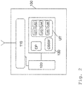
- Figure 2
- shows an exemplary embodiment of a communication node according to the present invention.
- The preferred embodiment of the present invention will be best understood by reference to the drawings. It will be readily understood that the present invention, as generally described and illustrated in the figures herein, could vary in a wide range. Thus, the following more detailed description of the exemplary embodiments of the present invention, as represented in the figures, is not intended to limit the scope of the invention, as claimed, but is merely representative of presently preferred embodiments of the invention.
-
Figure 1 shows an exemplary embodiment of acommunication system 10 according to the present invention. Thecommunication system 10 comprises a plurality of broadcast-type communication nodes - The
communication system 10 forms a token-ring system wherein each communication node directly or indirectly - i.e. via one or more other communication nodes - sends data signals D to an allocated downstream communication node and receives data signals D from an allocated upstream communication node. The data signals D are illustrated by arrows inFigure 1 . The arrows' directions indicate the direction of the communication and thus define for each communication node which of the other communication nodes is the respective upstream node and the respective downstream node. - In
Figure 1 , it is assumed thatcommunication nodes -
Figure 2 shows an exemplary embodiment of acommunication node 100 that can form any of thecommunication nodes communication system 10 ofFigure 1 . - The
communication node 100 comprises atransceiver 110 capable of transmitting and receiving electromagnetic radiation, aprocessor unit 120 and amemory 130. Thememory 130 stores a control program CP that allows theprocessor unit 120 to operate as explained further below. - The
memory 130 also stores a usability table UT that contains usability information regarding each communication channel that can be used by thecommunication node 100. For example, thecommunication node 100 may be configured to communicate on any of six given communication channels C1-C6. In this case, the usability table UT comprises usability information UI1, UI2, UI3, UI4, UI5 and UI6 for each of the six communication channels C1-C6, respectively. - Each usability information UI1, UI2, UI3, UI4, UI5 and UI6 at least indicates whether or not the respective communication channel C1-C6 can presently be used or not. For instance, a binary information "1" may indicate that the respective communication channel can presently be used, and a binary information "0" may indicate that the respective communication channel cannot be used. Of course, the assignment of the binary information "1" and "0" might also be inverse.
- Referring again to
Figure 1 , thecommunication nodes
Eachcommunication node communication nodes - In order to prepare for a situation where the presently used communication channel C1 is interrupted or disturbed, the
communication nodes communication system 10 and determine the current usability of the other communication channels C2-C6. - During the scanning procedure, the
communication nodes 
- In case of a time domain multiplexing system, P(C) can be obtained by using the following formula:

- In case of multiplexing systems that divide the channels in other domains (e.g. space, code, etc), P(C) can be obtained accordingly.
- Preferably, a communication channel is deemed to be usable for communication if the electromagnetic radiation on the respective communication channel is below a given threshold Pmax. Accordingly, a communication channel is preferably deemed to be unusable for communication if the electromagnetic radiation on the respective communication channel exceeds the given threshold Pmax:
- P(C) > Pmax => UI(C)="0" (communication channel unusable)
- P(C) < Pmax => UI(C)="1" (communication channel usable)
- Based on the evaluation of the measurement results, the usability information UI1-UI6 stored in memory 130 (see
Figure 2 ) can be updated. - In
Figure 1 , the scanning of the other communication channels C2-C6 is illustrated with respect tocommunication node 11, only. - In order to regularly update the stored usability information, the
communication nodes - Furthermore, each
communication node - Assuming for instance a situation where the communication channel C1 is the presently used communication channel and the usability tables UT stored in the
memory 130 of thecommunication nodes communication channel usability information UI(C) priority C1 1 1 C2 1 2 C3 0 3 C4 1 4 C5 0 5 C6 1 6 - According to the usability table UT above, the communication channels C2, C4 and C6 are presently usable and the communication channels C3 and C5 are presently unusable. Based on these table entries, each of the
communication nodes - The channel sequence is preferably determined based on a given scheme that is applied by all
communication nodes Figure 2 ) and responsible for determining the channel sequence based on the table entries of the usability table UT. - The given scheme may be based on a priority that is defined for each communication channel, e.g. as indicated in the exemplary table above. The priorities may define for instance that communication channel C2 is preferred over communication channel C4, and communication channel C4 is preferred over communication channel C6: Therefore, in the example presented above, the channel sequence C2-C4-C6 results.
- In order to avoid that usability information stored in the memories of the communication nodes 11-14 differ and therefore differing channel sequences might be generated, the communication nodes 11-14 preferably exchange their stored usability information or parts thereof and use received information to update or amend its stored usability information.
- If for instance the
communication node 13 stores the usability information UI4="0" and all theother communication nodes other communication nodes communication channel usability information UI(C) priority C1 1 1 C2 1 2 C3 0 3 C4 0 4 C5 0 5 C6 1 6 - The exchange of usability information between the communication nodes makes sure that all communication nodes refer to the same usability table when they determine their channel sequence.
- With respect to the updated usability table above, for instance, the channel sequence C2-C6 would be determined because communication channel C2 is preferred over communication channel C6. Accordingly, if any of the communication nodes does not receive data signals D within the given maximum time interval it will request a switch and/or will switch from the currently used communication channel C1 to the new communication channel C2. If, for whatever reason, the communication fails on channel C2, channel C6 can be tried thereafter.
Claims (14)
- Method of operating a communication system (10), that forms a token-ring system,
characterized in that
each communication node (11, 12, 13, 14) of the communication system (10) tracks a successful reception of data signals (D) and requests a switch and/or switches from a currently used communication channel (C1) to another communication channel (C2-C6) in case that no successful receptions were made within a given maximum time interval,
wherein- during successful reception of data signals, all communication nodes (11, 12, 13, 14) directly communicate with each other on the same channel,- in case that one or more of the communication nodes (11, 12, 13, 14) fail to make successful receptions within the given maximum time interval on the actual channel, the respective communication nodes (11, 12, 13, 14) send a broadcast signal to all other nodes in order to request the switch from the currently used communication channel (C1) to another communication channel (C2-C6) and- at least one communication node, preferably each communication node (11, 12, 13, 14), of the communication system (10) stores usability information (UI1-UI6) with respect to the communication channels (C1-C6) that can be used by the communication system (10). - Method of claim 1 wherein
at least one communication node, preferably each communication node (11, 12, 13, 14), of the communication system (10) evaluates the stored usability information (UI1-UI6) and determines a channel sequence that defines the order in which communication channels (C1-C6) are switched in case that the currently used communication channel (C1-C6) is interrupted or fails to provide the given minimum communication quality. - Method of any of the preceding claims wherein
at least one communication node, preferably each communication node (11, 12, 13, 14), regularly scans the communication channels (C1-C6) of the communication system (10) in order to determine the current usability of the communication channels (C1-C6) and to update the stored usability information (UI1-UI6). - Method of any of the preceding claims wherein
at least one communication node, preferably each communication node (11, 12, 13, 14), measures the electromagnetic radiation on each of the currently unused communication channels (C2-C6) and determines the current usability of the communication channels (C2-C6) based on the measurement values. - Method of any of the preceding claims wherein
at least one communication node, preferably each communication node (11, 12, 13, 14), sends data signals (D) to at least one other communication node (11, 12, 13, 14) of the communication system (10) and receives data signals (D) from at least one other communication node (11, 12, 13, 14) of the communication system (10) during communication time slots and scans the communication channels (C1-C6) at times outside of the communication time slots. - Method of any of the preceding claims wherein
at least one communication node, preferably each communication node (11, 12, 13, 14), informs at least one other communication node (11, 12, 13, 14) about communication channels (C1-C6) that are usable according to its stored usability information (UI1-UI6). - Method of any of the preceding claims wherein
at least one communication node, preferably each communication node (11, 12, 13, 14), informs at least one other communication node (11, 12, 13, 14) about communication channels (C1-C6) that are unusable according to its stored usability information (UI1-UI6). - Method of any of the preceding claims wherein- each of the communication nodes of the communication system (10) receives usability information (UI1-UI6) or parts thereof stored by at least one other communication node (11, 12, 13, 14) and uses the received information (UI1-UI6) to update or amend its stored usability information (UI1-UI6), and- each communication node (11, 12, 13, 14) of the communication system (10) sends its stored usability information (UI1-UI6) or parts thereof to at least one other communication node (11, 12, 13, 14) of the communication system (10) in order to allow the other communication node (11, 12, 13, 14) to update or amend the stored usability information (UI1-UI6).
- Method of any of the preceding claims wherein
wherein each communication node (11, 12, 13, 14) directly or indirectly - i.e. via one or more other communication nodes that function as relay nodes - sends data signals (D) to an allocated downstream communication node (11, 12, 13, 14) and receives data signals (D) from an allocated upstream communication node (11, 12, 13, 14). - Method of claim 9 wherein- each communication node (11, 12, 13, 14) receives usability information (UI1-UI6) or parts thereof from the respective upstream node (11, 12, 13, 14) and uses the received information (UI1-UI6) to update or amend its stored usability information (UI1-UI6), and- each communication node (11, 12, 13, 14) sends its stored usability information (UI1-UI6) or parts thereof to the respective downstream node (11, 12, 13, 14) in order to allow the downstream node (11, 12, 13, 14) to update the stored usability information (UI1-UI6).
- Method of any of the preceding claims 9-10wherein the communication node (11, 12, 13, 14) sends a broadcast signal (D) to request a change of the communication channel (C1-C6) if the communication node (11, 12, 13, 14) does not receive an expected data signal (D) from the allocated upstream communication node (11, 12, 13, 14) within a given maximum time interval.
- Method of any of the preceding claims wherein a reception of a data signal is deemed to be successful if the receiving entity is able to detect the data signal, decode the data signal, and proof the correctness of the data signal by deriving a first check value from the data signal and comparing it to a second check value that is enclosed in the received data signal (e.g., a cyclic redundancy check (CRC) value) .
- Communication node (11, 12, 13, 14) for a communication system (10) that forms a token-ring system,
characterized in that- the communication node (11, 12, 13, 14) is capable of communicating on the basis of any of a plurality of communication channels (C1-C6) wherein the node is configured to directly communicate with other nodes on the same channel during successful reception of data signals, and- the communication node (11, 12, 13, 14) is configured to store usability information (UI1-UI6) regarding the communication channels (C1-C6), and to switch and/or request a switch from a currently used communication channel (C1-C6) to another communication channel (C1-C6) in case that the currently used communication channel (C1-C6) is interrupted or fails to provide a given minimum communication quality, and- the communication node is a broadcast-type node and configured to carry out the step of sending a broadcast signal to all other nodes in order to request the switch from the currently used communication channel (C1) to another communication channel (C2-C6) in case that the communication node fails to make successful receptions within the given maximum time interval on the actual channel. - Communication system (10),
characterized in that
the communication system (10) comprises two or more communication nodes according to claim 13.
Applications Claiming Priority (2)
| Application Number | Priority Date | Filing Date | Title |
|---|---|---|---|
| EP15186408.9A EP3148277A1 (en) | 2015-09-23 | 2015-09-23 | Communication system |
| PCT/EP2016/072195 WO2017050705A1 (en) | 2015-09-23 | 2016-09-19 | Communication system |
Publications (2)
| Publication Number | Publication Date |
|---|---|
| EP3354095A1 EP3354095A1 (en) | 2018-08-01 |
| EP3354095B1 true EP3354095B1 (en) | 2020-04-01 |
Family
ID=54251944
Family Applications (2)
| Application Number | Title | Priority Date | Filing Date |
|---|---|---|---|
| EP15186408.9A Withdrawn EP3148277A1 (en) | 2015-09-23 | 2015-09-23 | Communication system |
| EP16778230.9A Active EP3354095B1 (en) | 2015-09-23 | 2016-09-19 | Communication system |
Family Applications Before (1)
| Application Number | Title | Priority Date | Filing Date |
|---|---|---|---|
| EP15186408.9A Withdrawn EP3148277A1 (en) | 2015-09-23 | 2015-09-23 | Communication system |
Country Status (5)
| Country | Link |
|---|---|
| US (1) | US10680850B2 (en) |
| EP (2) | EP3148277A1 (en) |
| JP (2) | JP2018532355A (en) |
| CN (1) | CN107852735B (en) |
| WO (1) | WO2017050705A1 (en) |
Families Citing this family (2)
| Publication number | Priority date | Publication date | Assignee | Title |
|---|---|---|---|---|
| JP2019004223A (en) * | 2017-06-12 | 2019-01-10 | ルネサスエレクトロニクス株式会社 | Wireless communication device, and program for controlling communication mode of wireless communication device |
| EP3454511A1 (en) | 2017-09-11 | 2019-03-13 | R3 - Reliable Realtime Radio Communications GmbH | Communication node for a sequence-based communication network |
Family Cites Families (18)
| Publication number | Priority date | Publication date | Assignee | Title |
|---|---|---|---|---|
| JP3769559B2 (en) * | 2003-03-24 | 2006-04-26 | 株式会社アルファシステムズ | ACCESS CONTROL METHOD IN WIRELESS TRANSMISSION PATH, WIRELESS TRANSMISSION DEVICE, WIRELESS TRANSMISSION SYSTEM, AND ACCESS CONTROL PROGRAM IN WIRELESS TRANSMISSION PATH |
| US20080020751A1 (en) * | 2005-09-27 | 2008-01-24 | Qualcomm Incorporated | Channel monitoring methods in a wireless broadcast system |
| KR100700948B1 (en) * | 2006-05-25 | 2007-03-28 | 삼성전자주식회사 | Apparatus and method for data transmission using multiple channels of wireless LAN in mobile communication system |
| US7720086B2 (en) * | 2007-03-19 | 2010-05-18 | Microsoft Corporation | Distributed overlay multi-channel media access control for wireless ad hoc networks |
| TWI355826B (en) * | 2007-08-20 | 2012-01-01 | Univ Nat Taiwan Science Tech | Data transmitting method with multiple token macha |
| JP5356891B2 (en) * | 2009-04-03 | 2013-12-04 | エヌ・ティ・ティ・コミュニケーションズ株式会社 | Sensor network system, sensor network control method, and reader |
| US8533554B2 (en) | 2009-04-23 | 2013-09-10 | Lg Electronics Inc. | Method and apparatus for implementing a HARQ in a multi-carrier system |
| CN102340395B (en) * | 2010-07-22 | 2014-07-02 | 富士通株式会社 | Communication method and node for wireless communication network |
| US9155019B2 (en) * | 2010-08-11 | 2015-10-06 | Thomson Licensing | Combining bandwidth aware routing with channel selection and switching in a multi-hop wireless home network |
| JP2012114513A (en) * | 2010-11-19 | 2012-06-14 | Toshiba Corp | Radio communication apparatus |
| CN102137452B (en) * | 2011-03-08 | 2013-06-05 | 东南大学 | Method based on multi-channel medium access control protocol in ad hoc network |
| GB2501420A (en) * | 2011-04-14 | 2013-10-23 | Renesas Mobile Corp | Switching to alternative communication channels to enhance reliability in shared bands |
| JP5782954B2 (en) * | 2011-09-21 | 2015-09-24 | 沖電気工業株式会社 | Communication device, communication program, node device, and network |
| US8792406B2 (en) * | 2012-01-30 | 2014-07-29 | Itron, Inc. | Data broadcasting with a prepare-to-broadcast message |
| JP5047394B2 (en) * | 2012-03-02 | 2012-10-10 | 京セラ株式会社 | Wireless communication system, base station apparatus, and wireless communication method |
| DE102012206529B4 (en) | 2012-04-20 | 2026-03-26 | R3 Solutions Gmbh | Wireless real-time transmission system |
| US9305358B2 (en) * | 2013-07-01 | 2016-04-05 | Kabushiki Kaisha Toshiba | Medical image processing |
| KR102024352B1 (en) * | 2013-07-31 | 2019-11-04 | 한국전자통신연구원 | Method for data transmission and management of channel in wireless sensor networks |
-
2015
- 2015-09-23 EP EP15186408.9A patent/EP3148277A1/en not_active Withdrawn
-
2016
- 2016-09-19 WO PCT/EP2016/072195 patent/WO2017050705A1/en not_active Ceased
- 2016-09-19 US US15/759,657 patent/US10680850B2/en active Active
- 2016-09-19 CN CN201680046177.2A patent/CN107852735B/en not_active Expired - Fee Related
- 2016-09-19 JP JP2018534016A patent/JP2018532355A/en active Pending
- 2016-09-19 EP EP16778230.9A patent/EP3354095B1/en active Active
-
2021
- 2021-07-08 JP JP2021113484A patent/JP2021170797A/en active Pending
Non-Patent Citations (1)
| Title |
|---|
| None * |
Also Published As
| Publication number | Publication date |
|---|---|
| EP3354095A1 (en) | 2018-08-01 |
| CN107852735B (en) | 2022-07-29 |
| US20190089556A1 (en) | 2019-03-21 |
| US10680850B2 (en) | 2020-06-09 |
| JP2021170797A (en) | 2021-10-28 |
| EP3148277A1 (en) | 2017-03-29 |
| JP2018532355A (en) | 2018-11-01 |
| WO2017050705A1 (en) | 2017-03-30 |
| CN107852735A (en) | 2018-03-27 |
Similar Documents
| Publication | Publication Date | Title |
|---|---|---|
| JP7232948B2 (en) | Terminal, random access method, base station, and communication system | |
| JP7672529B2 (en) | Resource allocation for beam failure recovery procedures. | |
| CN111727655B (en) | Methods for providing RACH opportunity indication and related wireless terminals and base stations | |
| EP3656164B1 (en) | Method and system for managing ue-to-ue interference in a mobile telecommunication network | |
| TW202007196A (en) | Method for data transmission in sidelink and terminal device | |
| KR101986113B1 (en) | Method and system for signalling and processing control information in a mobile broadband network environment | |
| US10728724B2 (en) | Communication device and wireless communication method | |
| US7990997B2 (en) | Contention based media access mechanism | |
| CN113711522B (en) | Effective signaling in rate matching mode | |
| EP4226729B1 (en) | Method and apparatus for random access in wireless communication system | |
| CN114071760A (en) | Data communication method, device, electronic equipment and storage medium | |
| US9998972B2 (en) | Radio resource management method and apparatus for transmitting and receiving handover message in mobile communication system | |
| KR20230016612A (en) | Channel access procedure | |
| EP3573400B1 (en) | Method for reassigning root sequence index and apparatus therefor | |
| CN108632920B (en) | System information transmission method and device | |
| EP2053803B1 (en) | Wireless communication system, base station, and transmitting method for ranging operation | |
| US10680850B2 (en) | Communication system | |
| EP3501206B1 (en) | Risk aware validity assessment of system information | |
| EP3501223B1 (en) | Apparatus and method for allocating radio resources | |
| JP7611790B2 (en) | Base station device, repeater device, wireless communication system, and control method and program thereof | |
| GB2584746A (en) | Improvements in and relating to random access in a telecommunication system | |
| WO2025031625A1 (en) | Apparatus, methods and computer programs relating to transmission configuration indicator states |
Legal Events
| Date | Code | Title | Description |
|---|---|---|---|
| STAA | Information on the status of an ep patent application or granted ep patent |
Free format text: STATUS: UNKNOWN |
|
| STAA | Information on the status of an ep patent application or granted ep patent |
Free format text: STATUS: THE INTERNATIONAL PUBLICATION HAS BEEN MADE |
|
| PUAI | Public reference made under article 153(3) epc to a published international application that has entered the european phase |
Free format text: ORIGINAL CODE: 0009012 |
|
| STAA | Information on the status of an ep patent application or granted ep patent |
Free format text: STATUS: REQUEST FOR EXAMINATION WAS MADE |
|
| 17P | Request for examination filed |
Effective date: 20180410 |
|
| AK | Designated contracting states |
Kind code of ref document: A1 Designated state(s): AL AT BE BG CH CY CZ DE DK EE ES FI FR GB GR HR HU IE IS IT LI LT LU LV MC MK MT NL NO PL PT RO RS SE SI SK SM TR |
|
| AX | Request for extension of the european patent |
Extension state: BA ME |
|
| DAV | Request for validation of the european patent (deleted) | ||
| DAX | Request for extension of the european patent (deleted) | ||
| STAA | Information on the status of an ep patent application or granted ep patent |
Free format text: STATUS: EXAMINATION IS IN PROGRESS |
|
| 17Q | First examination report despatched |
Effective date: 20190226 |
|
| REG | Reference to a national code |
Ref country code: DE Ref legal event code: R079 Ref document number: 602016033132 Country of ref document: DE Free format text: PREVIOUS MAIN CLASS: H04W0072080000 Ipc: H04W0072020000 |
|
| GRAP | Despatch of communication of intention to grant a patent |
Free format text: ORIGINAL CODE: EPIDOSNIGR1 |
|
| STAA | Information on the status of an ep patent application or granted ep patent |
Free format text: STATUS: GRANT OF PATENT IS INTENDED |
|
| RIC1 | Information provided on ipc code assigned before grant |
Ipc: H04W 72/08 20090101ALI20191014BHEP Ipc: H04L 1/22 20060101ALI20191014BHEP Ipc: H04W 72/02 20090101AFI20191014BHEP |
|
| INTG | Intention to grant announced |
Effective date: 20191104 |
|
| GRAS | Grant fee paid |
Free format text: ORIGINAL CODE: EPIDOSNIGR3 |
|
| GRAA | (expected) grant |
Free format text: ORIGINAL CODE: 0009210 |
|
| STAA | Information on the status of an ep patent application or granted ep patent |
Free format text: STATUS: THE PATENT HAS BEEN GRANTED |
|
| RAP1 | Party data changed (applicant data changed or rights of an application transferred) |
Owner name: R3 - RELIABLE REALTIME RADIO COMMUNICATIONS GMBH |
|
| AK | Designated contracting states |
Kind code of ref document: B1 Designated state(s): AL AT BE BG CH CY CZ DE DK EE ES FI FR GB GR HR HU IE IS IT LI LT LU LV MC MK MT NL NO PL PT RO RS SE SI SK SM TR |
|
| REG | Reference to a national code |
Ref country code: GB Ref legal event code: FG4D |
|
| REG | Reference to a national code |
Ref country code: CH Ref legal event code: EP Ref country code: AT Ref legal event code: REF Ref document number: 1253019 Country of ref document: AT Kind code of ref document: T Effective date: 20200415 |
|
| REG | Reference to a national code |
Ref country code: DE Ref legal event code: R096 Ref document number: 602016033132 Country of ref document: DE |
|
| REG | Reference to a national code |
Ref country code: IE Ref legal event code: FG4D |
|
| REG | Reference to a national code |
Ref country code: DE Ref legal event code: R081 Ref document number: 602016033132 Country of ref document: DE Owner name: R3 SOLUTIONS GMBH, DE Free format text: FORMER OWNER: R3 - RELIABLE REALTIME RADIO COMMUNICATIONS GMBH, 14059 BERLIN, DE Ref country code: DE Ref legal event code: R082 Ref document number: 602016033132 Country of ref document: DE Representative=s name: FISCHER, UWE, DIPL.-ING. DR.-ING., DE |
|
| PG25 | Lapsed in a contracting state [announced via postgrant information from national office to epo] |
Ref country code: BG Free format text: LAPSE BECAUSE OF FAILURE TO SUBMIT A TRANSLATION OF THE DESCRIPTION OR TO PAY THE FEE WITHIN THE PRESCRIBED TIME-LIMIT Effective date: 20200701 |
|
| REG | Reference to a national code |
Ref country code: NL Ref legal event code: MP Effective date: 20200401 |
|
| REG | Reference to a national code |
Ref country code: LT Ref legal event code: MG4D |
|
| PG25 | Lapsed in a contracting state [announced via postgrant information from national office to epo] |
Ref country code: FI Free format text: LAPSE BECAUSE OF FAILURE TO SUBMIT A TRANSLATION OF THE DESCRIPTION OR TO PAY THE FEE WITHIN THE PRESCRIBED TIME-LIMIT Effective date: 20200401 Ref country code: GR Free format text: LAPSE BECAUSE OF FAILURE TO SUBMIT A TRANSLATION OF THE DESCRIPTION OR TO PAY THE FEE WITHIN THE PRESCRIBED TIME-LIMIT Effective date: 20200702 Ref country code: NO Free format text: LAPSE BECAUSE OF FAILURE TO SUBMIT A TRANSLATION OF THE DESCRIPTION OR TO PAY THE FEE WITHIN THE PRESCRIBED TIME-LIMIT Effective date: 20200701 Ref country code: IS Free format text: LAPSE BECAUSE OF FAILURE TO SUBMIT A TRANSLATION OF THE DESCRIPTION OR TO PAY THE FEE WITHIN THE PRESCRIBED TIME-LIMIT Effective date: 20200801 Ref country code: SE Free format text: LAPSE BECAUSE OF FAILURE TO SUBMIT A TRANSLATION OF THE DESCRIPTION OR TO PAY THE FEE WITHIN THE PRESCRIBED TIME-LIMIT Effective date: 20200401 Ref country code: PT Free format text: LAPSE BECAUSE OF FAILURE TO SUBMIT A TRANSLATION OF THE DESCRIPTION OR TO PAY THE FEE WITHIN THE PRESCRIBED TIME-LIMIT Effective date: 20200817 Ref country code: LT Free format text: LAPSE BECAUSE OF FAILURE TO SUBMIT A TRANSLATION OF THE DESCRIPTION OR TO PAY THE FEE WITHIN THE PRESCRIBED TIME-LIMIT Effective date: 20200401 Ref country code: NL Free format text: LAPSE BECAUSE OF FAILURE TO SUBMIT A TRANSLATION OF THE DESCRIPTION OR TO PAY THE FEE WITHIN THE PRESCRIBED TIME-LIMIT Effective date: 20200401 Ref country code: CZ Free format text: LAPSE BECAUSE OF FAILURE TO SUBMIT A TRANSLATION OF THE DESCRIPTION OR TO PAY THE FEE WITHIN THE PRESCRIBED TIME-LIMIT Effective date: 20200401 |
|
| REG | Reference to a national code |
Ref country code: AT Ref legal event code: MK05 Ref document number: 1253019 Country of ref document: AT Kind code of ref document: T Effective date: 20200401 |
|
| PG25 | Lapsed in a contracting state [announced via postgrant information from national office to epo] |
Ref country code: HR Free format text: LAPSE BECAUSE OF FAILURE TO SUBMIT A TRANSLATION OF THE DESCRIPTION OR TO PAY THE FEE WITHIN THE PRESCRIBED TIME-LIMIT Effective date: 20200401 Ref country code: LV Free format text: LAPSE BECAUSE OF FAILURE TO SUBMIT A TRANSLATION OF THE DESCRIPTION OR TO PAY THE FEE WITHIN THE PRESCRIBED TIME-LIMIT Effective date: 20200401 Ref country code: RS Free format text: LAPSE BECAUSE OF FAILURE TO SUBMIT A TRANSLATION OF THE DESCRIPTION OR TO PAY THE FEE WITHIN THE PRESCRIBED TIME-LIMIT Effective date: 20200401 |
|
| PG25 | Lapsed in a contracting state [announced via postgrant information from national office to epo] |
Ref country code: AL Free format text: LAPSE BECAUSE OF FAILURE TO SUBMIT A TRANSLATION OF THE DESCRIPTION OR TO PAY THE FEE WITHIN THE PRESCRIBED TIME-LIMIT Effective date: 20200401 |
|
| REG | Reference to a national code |
Ref country code: DE Ref legal event code: R097 Ref document number: 602016033132 Country of ref document: DE |
|
| PG25 | Lapsed in a contracting state [announced via postgrant information from national office to epo] |
Ref country code: AT Free format text: LAPSE BECAUSE OF FAILURE TO SUBMIT A TRANSLATION OF THE DESCRIPTION OR TO PAY THE FEE WITHIN THE PRESCRIBED TIME-LIMIT Effective date: 20200401 Ref country code: DK Free format text: LAPSE BECAUSE OF FAILURE TO SUBMIT A TRANSLATION OF THE DESCRIPTION OR TO PAY THE FEE WITHIN THE PRESCRIBED TIME-LIMIT Effective date: 20200401 Ref country code: IT Free format text: LAPSE BECAUSE OF FAILURE TO SUBMIT A TRANSLATION OF THE DESCRIPTION OR TO PAY THE FEE WITHIN THE PRESCRIBED TIME-LIMIT Effective date: 20200401 Ref country code: SM Free format text: LAPSE BECAUSE OF FAILURE TO SUBMIT A TRANSLATION OF THE DESCRIPTION OR TO PAY THE FEE WITHIN THE PRESCRIBED TIME-LIMIT Effective date: 20200401 Ref country code: EE Free format text: LAPSE BECAUSE OF FAILURE TO SUBMIT A TRANSLATION OF THE DESCRIPTION OR TO PAY THE FEE WITHIN THE PRESCRIBED TIME-LIMIT Effective date: 20200401 Ref country code: RO Free format text: LAPSE BECAUSE OF FAILURE TO SUBMIT A TRANSLATION OF THE DESCRIPTION OR TO PAY THE FEE WITHIN THE PRESCRIBED TIME-LIMIT Effective date: 20200401 Ref country code: ES Free format text: LAPSE BECAUSE OF FAILURE TO SUBMIT A TRANSLATION OF THE DESCRIPTION OR TO PAY THE FEE WITHIN THE PRESCRIBED TIME-LIMIT Effective date: 20200401 |
|
| PLBE | No opposition filed within time limit |
Free format text: ORIGINAL CODE: 0009261 |
|
| STAA | Information on the status of an ep patent application or granted ep patent |
Free format text: STATUS: NO OPPOSITION FILED WITHIN TIME LIMIT |
|
| PG25 | Lapsed in a contracting state [announced via postgrant information from national office to epo] |
Ref country code: PL Free format text: LAPSE BECAUSE OF FAILURE TO SUBMIT A TRANSLATION OF THE DESCRIPTION OR TO PAY THE FEE WITHIN THE PRESCRIBED TIME-LIMIT Effective date: 20200401 Ref country code: SK Free format text: LAPSE BECAUSE OF FAILURE TO SUBMIT A TRANSLATION OF THE DESCRIPTION OR TO PAY THE FEE WITHIN THE PRESCRIBED TIME-LIMIT Effective date: 20200401 |
|
| 26N | No opposition filed |
Effective date: 20210112 |
|
| REG | Reference to a national code |
Ref country code: CH Ref legal event code: PL |
|
| GBPC | Gb: european patent ceased through non-payment of renewal fee |
Effective date: 20200919 |
|
| PG25 | Lapsed in a contracting state [announced via postgrant information from national office to epo] |
Ref country code: SI Free format text: LAPSE BECAUSE OF FAILURE TO SUBMIT A TRANSLATION OF THE DESCRIPTION OR TO PAY THE FEE WITHIN THE PRESCRIBED TIME-LIMIT Effective date: 20200401 |
|
| REG | Reference to a national code |
Ref country code: BE Ref legal event code: MM Effective date: 20200930 |
|
| PG25 | Lapsed in a contracting state [announced via postgrant information from national office to epo] |
Ref country code: LU Free format text: LAPSE BECAUSE OF NON-PAYMENT OF DUE FEES Effective date: 20200919 |
|
| PG25 | Lapsed in a contracting state [announced via postgrant information from national office to epo] |
Ref country code: CH Free format text: LAPSE BECAUSE OF NON-PAYMENT OF DUE FEES Effective date: 20200930 Ref country code: BE Free format text: LAPSE BECAUSE OF NON-PAYMENT OF DUE FEES Effective date: 20200930 Ref country code: LI Free format text: LAPSE BECAUSE OF NON-PAYMENT OF DUE FEES Effective date: 20200930 Ref country code: GB Free format text: LAPSE BECAUSE OF NON-PAYMENT OF DUE FEES Effective date: 20200919 Ref country code: IE Free format text: LAPSE BECAUSE OF NON-PAYMENT OF DUE FEES Effective date: 20200919 |
|
| PG25 | Lapsed in a contracting state [announced via postgrant information from national office to epo] |
Ref country code: TR Free format text: LAPSE BECAUSE OF FAILURE TO SUBMIT A TRANSLATION OF THE DESCRIPTION OR TO PAY THE FEE WITHIN THE PRESCRIBED TIME-LIMIT Effective date: 20200401 Ref country code: MT Free format text: LAPSE BECAUSE OF FAILURE TO SUBMIT A TRANSLATION OF THE DESCRIPTION OR TO PAY THE FEE WITHIN THE PRESCRIBED TIME-LIMIT Effective date: 20200401 Ref country code: CY Free format text: LAPSE BECAUSE OF FAILURE TO SUBMIT A TRANSLATION OF THE DESCRIPTION OR TO PAY THE FEE WITHIN THE PRESCRIBED TIME-LIMIT Effective date: 20200401 |
|
| PG25 | Lapsed in a contracting state [announced via postgrant information from national office to epo] |
Ref country code: MK Free format text: LAPSE BECAUSE OF FAILURE TO SUBMIT A TRANSLATION OF THE DESCRIPTION OR TO PAY THE FEE WITHIN THE PRESCRIBED TIME-LIMIT Effective date: 20200401 Ref country code: MC Free format text: LAPSE BECAUSE OF FAILURE TO SUBMIT A TRANSLATION OF THE DESCRIPTION OR TO PAY THE FEE WITHIN THE PRESCRIBED TIME-LIMIT Effective date: 20200401 |
|
| REG | Reference to a national code |
Ref country code: DE Ref legal event code: R081 Ref document number: 602016033132 Country of ref document: DE Owner name: R3 SOLUTIONS GMBH, DE Free format text: FORMER OWNER: R3 - RELIABLE REALTIME RADIO COMMUNICATIONS GMBH, 10625 BERLIN, DE |
|
| PGFP | Annual fee paid to national office [announced via postgrant information from national office to epo] |
Ref country code: FR Payment date: 20230919 Year of fee payment: 8 Ref country code: DE Payment date: 20230930 Year of fee payment: 8 |
|
| REG | Reference to a national code |
Ref country code: DE Ref legal event code: R119 Ref document number: 602016033132 Country of ref document: DE |
|
| PG25 | Lapsed in a contracting state [announced via postgrant information from national office to epo] |
Ref country code: DE Free format text: LAPSE BECAUSE OF NON-PAYMENT OF DUE FEES Effective date: 20250401 |
|
| PG25 | Lapsed in a contracting state [announced via postgrant information from national office to epo] |
Ref country code: FR Free format text: LAPSE BECAUSE OF NON-PAYMENT OF DUE FEES Effective date: 20240930 |