EP3353647B1 - External process user interface isolation and monitoring - Google Patents
External process user interface isolation and monitoring Download PDFInfo
- Publication number
- EP3353647B1 EP3353647B1 EP16778927.0A EP16778927A EP3353647B1 EP 3353647 B1 EP3353647 B1 EP 3353647B1 EP 16778927 A EP16778927 A EP 16778927A EP 3353647 B1 EP3353647 B1 EP 3353647B1
- Authority
- EP
- European Patent Office
- Prior art keywords
- external
- processes
- hosting application
- responsive
- logic
- Prior art date
- Legal status (The legal status is an assumption and is not a legal conclusion. Google has not performed a legal analysis and makes no representation as to the accuracy of the status listed.)
- Active
Links
Images





Classifications
-
- H—ELECTRICITY
- H04—ELECTRIC COMMUNICATION TECHNIQUE
- H04L—TRANSMISSION OF DIGITAL INFORMATION, e.g. TELEGRAPHIC COMMUNICATION
- H04L43/00—Arrangements for monitoring or testing data switching networks
- H04L43/04—Processing captured monitoring data, e.g. for logfile generation
-
- G—PHYSICS
- G06—COMPUTING OR CALCULATING; COUNTING
- G06F—ELECTRIC DIGITAL DATA PROCESSING
- G06F11/00—Error detection; Error correction; Monitoring
- G06F11/07—Responding to the occurrence of a fault, e.g. fault tolerance
- G06F11/0703—Error or fault processing not based on redundancy, i.e. by taking additional measures to deal with the error or fault not making use of redundancy in operation, in hardware, or in data representation
- G06F11/0751—Error or fault detection not based on redundancy
- G06F11/0754—Error or fault detection not based on redundancy by exceeding limits
- G06F11/0757—Error or fault detection not based on redundancy by exceeding limits by exceeding a time limit, i.e. time-out, e.g. watchdogs
-
- G—PHYSICS
- G06—COMPUTING OR CALCULATING; COUNTING
- G06F—ELECTRIC DIGITAL DATA PROCESSING
- G06F9/00—Arrangements for program control, e.g. control units
- G06F9/06—Arrangements for program control, e.g. control units using stored programs, i.e. using an internal store of processing equipment to receive or retain programs
- G06F9/44—Arrangements for executing specific programs
- G06F9/451—Execution arrangements for user interfaces
-
- G—PHYSICS
- G06—COMPUTING OR CALCULATING; COUNTING
- G06F—ELECTRIC DIGITAL DATA PROCESSING
- G06F9/00—Arrangements for program control, e.g. control units
- G06F9/06—Arrangements for program control, e.g. control units using stored programs, i.e. using an internal store of processing equipment to receive or retain programs
- G06F9/44—Arrangements for executing specific programs
- G06F9/451—Execution arrangements for user interfaces
- G06F9/452—Remote windowing, e.g. X-Window System, desktop virtualisation
-
- H—ELECTRICITY
- H04—ELECTRIC COMMUNICATION TECHNIQUE
- H04L—TRANSMISSION OF DIGITAL INFORMATION, e.g. TELEGRAPHIC COMMUNICATION
- H04L41/00—Arrangements for maintenance, administration or management of data switching networks, e.g. of packet switching networks
- H04L41/22—Arrangements for maintenance, administration or management of data switching networks, e.g. of packet switching networks comprising specially adapted graphical user interfaces [GUI]
Definitions
- computing systems There are a wide variety of different types of computing systems. Some computing systems are used by organizations that perform customer service or contact center operations. In such systems, a hosting application shows multi-dimensional information on a single user interface from various external applications (or external processes).
- Some such systems provide the ability to configure a single user interface that combines user interfaces from various external applications (or external processes) that can be hosted within the hosting application (or parent) user interface.
- the external applications (or external processes) can crash or otherwise become nonresponsive.
- the hosting application renders different user interfaces from the different processes to create the unified view, and because the hosting application has little or no control over the external applications (or processes), the external applications (or processes) can cause the hosting application, itself, to crash or become nonresponsive. This can essentially block the entire hosting application, since all of the user interfaces are rendered on a single UI thread that belongs to the hosting application.
- a device for operating an apparatus includes a server, a central monitoring module, an apparatus for communicating between the server and the monitoring module, a plurality of control, maintainance and/or monitoring programs and an apparatus for communicating between the control, maintenance and/or monitoring programs on the one hand as well the server and/or the monitoring module on the other hand.
- a browser can be connected to the device so that a system for the operation of the apparatus derives therefrom.
- a user interface with security-related functions or interactive functions can be realized easily and with little programming outlay.
- User interfaces for multiple external processes are hosted in a single user interface (UI) threaded host application.
- a broker process (or broker window) is created in the hosting application for each external process user interface window.
- a monitor monitors the state of the hosting application and, if it becomes nonresponsive, identifies each of the external processes that are nonresponsive, and issues a notification to terminate the identified external processes.
- FIG. 1 is a block diagram of one example of a computing system architecture 100.
- Architecture 100 illustratively includes computing system 102 and one or more client systems 104.
- FIG. 1 shows that, in one example, computing system 102 illustratively generates user interfaces 106 for interaction by user 108. User 108 can illustratively interact with user interfaces 106 to control and manipulate computing system 102.
- client system 104 illustratively generates user interfaces 110 for interaction by user 112. User 112 can illustratively interact with user interfaces 110 in order to control and manipulate client system 104.
- computing system 102 illustratively includes one or more processors or servers 114, operating system 116 (which can include a message handling logic 118 and other operating system functionality 120), data store 122, user interface component 124, external process user interface (UI) hosting system 126, and it can include other items 128.
- external process UI hosting system 126 can include a set of hosting functionality 130, isolation system 132, monitoring system 134, and it can include other items 136.
- FIG. 1 also shows that client system 104 illustratively includes one or more client components 162, one or more processors 164, user interface component 166 and data store 168. It can include other client functionality 170 as well.
- Hosting functionality 130 illustratively hosts user interfaces for various external processes (such as processes that can be run on client system 104).
- Isolation system 132 illustratively isolates those user interfaces, and monitoring system 134 monitors the hosting functionality 130 as well as the external processes, to determine whether they are in a nonresponsive state. This is described in greater detail below.
- Isolation system 132 itself, includes broker process generation logic 138, new process details notification logic 140, attachment/detachment logic 142, and it can include other items 144.
- Monitoring system 134 itself, illustratively includes child process identifier logic 146, monitor list generator logic 148, host system monitor logic 150, non-responding external process identifier logic 152, monitor data store 154 (which can include external process monitor list 156, and other items 158), and it can include other items 160.
- External process UI hosting system 126 illustratively hosts the user interface(s) of multiple external processes (which can be run, for instance, on client system 104) inside a tabbed layout in a single user interface threaded application which can be run by hosting functionality 130.
- isolation system 132 illustratively generates a broker process for each external process user interface (or window) that is hosted.
- Monitoring system 134 monitors the hosting application to identify whether it enters a non-responsive state. If so, it iterates through all of the hosted, external processes, to identify which of those is in a nonresponsive state.
- isolation system 132 It then identifies, to isolation system 132, which of the external processes are nonresponsive, and isolation system 132 can terminate the broker process that is managing that external process.
- This type of isolation and monitoring enables the main hosting application run by hosting functionality 130 to maintain access to all of the other external processes, without becoming nonresponsive, based upon one or more of the external processes, themselves, being nonresponsive.
- FIG. 2 is a block diagram illustrating one example of a main hosting process 171 that can be run by a main hosting application that hosts user interfaces for a set of external processes 172, 174 and 176 (each of which can have its own UI or window). It can be seen that the main hosting process 171 includes a host process user interface 178. It also includes a separate broker process window (or broker process user interface) 180, 182 and 184, corresponding to each of the external processes 172-176. Hosting process 171 is also illustratively coupled to, and managing, the interfaces for a communication channel 186 that provides communication with monitoring system 134 (shown in FIG. 1 ).
- monitoring system 134 accesses each of the broker process user interfaces (or windows) 180-184 to determine which (if any) external processes 172-176 have become nonresponsive. It can then send a message to message handling component 118 in operating system 116 to indicate that the corresponding broker process window 180-184 should be terminated (or detached) from host process user interface 178.
- the host process user interface 178 can then terminate the corresponding broker process windows 180-184, while maintaining its connection to the other broker process windows 180-184 (and therefore maintaining accessibility to the other external processes that are still responsive).
- the broker process window (or a new broker process window) for that external process can be generated and reattached to the host process user interface 178.
- FIG. 3 is a flow diagram illustrating one example of the operation of external UI hosting system 126 in identifying new process user interfaces that it will be hosting, and communicating that information to monitoring system 134 so that monitoring system 134 can enter it in external process monitor list 156. It is fist assumed that the main external process hosting application is started. This can be started, for instance, in hosting functionality 130. This is indicated by block 200 in FIG. 3 .
- the hosting application (or another set of logic or component) spawns an instance of a monitoring process that can be implemented by monitoring system 134. Spawning the monitoring process is indicated by block 202.
- the main external process hosting application will begin to host user interfaces for external processes.
- attachment/detachment logic 142 controls broker process generation logic 138 to generate a broker process (which has a broker process window) for the new external process to be hosted. This is so the hosting application 130 can detach itself from the corresponding external process (should it become non-responsive) by terminating its corresponding broker process.
- New process details notification logic 140 then notifies monitoring system 134 of the details of the new process, for which a user interface is to be hosted by the main process hosting application. Notifying the monitoring system 134 of the new process details is indicated by block 204 in FIG. 3 .
- Child process identifier logic 146 locates the new process, based upon the details that have been provided. This is indicated by block 206. Monitor list generator logic 148 then determines whether the new process has one or more child processes. This is indicated by block 206. If so, then child process identifier logic 146 identifies the details of each of the child processes. This is indicated by block 210.
- Monitor list generator logic 148 then adds the new process (and any of its child processes) into the external process monitor list 156. This is indicated by block 212.
- monitoring system 134 can begin monitoring the main external process hosting application, as well as the external processes.
- host system monitor logic 150 monitors the main external process hosting application to determine whether it has become nonresponsive, and non-responding external process identifier logic 152 identifies which, if any, of the external processes have caused the main hosting application to become nonresponsive, so their broker processes can be terminated. This is now described in greater detail below with respect to FIGS. 4 and 5 .
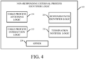
- FIG. 4 is a block diagram showing one example of non-responding external process identifier logic 152 in more detail.
- logic 152 includes child process accessing logic 220, child process iteration logic 222, responsiveness identifier logic 224, termination notifier logic 226, and it can include other items 228.
- child process accessing logic 220 identifies various child processes that are having their UIs hosted by the main hosting application.
- Child process iteration logic 222 iterates through each of the child process UIs, and responsiveness identifier logic 224 identifies which of them, if any, have become nonresponsive.
- Termination notifier logic 226 then sends a notification indicating that the broker processes for the nonresponsive external process UIs should be terminated.
- FIG. 5 is a flow diagram illustrating one example of the operation of monitoring system 134, in identifying nonresponsive processes, in more detail.
- host system monitoring logic 150 determines whether it is time to monitor the main hosting application to determine whether it has become nonresponsive. This can be done in a wide variety of different ways. In one example, host system monitor logic 150 continuously polls the main hosting application to ensure that it is still responsive. In another example, it can poll the main hosting application intermittently, periodically, or based on other triggering criteria. All of these are contemplated herein. Determining that it is time to monitor the main hosting application is indicated by block 250 in FIG. 5 .
- host system monitor logic 150 checks to determine whether it is responsive. This is indicated by block 252. For instance, it can monitor the activity of the main hosting application for a configurable amount of time. This is indicated by block 254. It can send various different types of messages to the hosting application to determine whether it is responsive or nonresponsive. This is indicated by block 256. It can identify the state of responsiveness of the main hosting application in other ways as well, and this is indicated by block 258.
- non-responding external process identifier logic 152 begins to determine which, if any, of the processes in the external process monitor list 156 have become nonresponsive.
- child process accessing logic 220 first selects a process from the monitor list, and responsiveness identifier logic 224 determines whether the selected process is responding. This is indicated by blocks 262 and 264 in FIG. 5 .
- responsiveness identifier logic 224 notifies the main hosting application of the details of the selected process, and also indicating that it is nonresponsive. This is indicated by block 266. This can allow the main hosting application to perform certain activities. For instance, it may wish to log the state of the external process, or various details about the external process, before the external process is terminated.
- responsiveness identifier logic 224 can also determine whether the selected process responded during the previous monitoring cycle. This is indicated by block 268. If so, it may wait to send (or delay in sending) a termination notification for the selected process, allowing the selected process to recover, if possible.
- termination notifier logic 226 illustratively sends message handling logic 118 in operating system 116 a message or notification that the broker process corresponding to the selected, nonresponsive process, should be terminated. This is indicated by block 270.
- the message handling system 118 can communicate this message to the main hosting application which, at its discretion, can then terminate the broker process for the nonresponsive external process.
- Child process iteration logic 222 iterates through all of the external processes in the external process monitor list 156, until all of them have been checked for responsiveness. This is indicated by block 272 in FIG. 5 .
- the external processes that have user interfaces hosted by the main hosting application are isolated. This is done by generating a broker process corresponding to each of the external processes. Because the broker process is generated within the main hosting application, the main hosting application can detach itself from any external processes that become nonresponsive. However, it can maintain an attachment with other external processes that are still responding.
- the monitoring system first monitors the main hosting application to identify when it has become nonresponsive, itself. When this happens, the monitoring system iterates through all of the external processes that have user interfaces hosted by the main hosting application, and identifies which of those, if any, have become nonresponsive. It can then issue a notification to terminate the corresponding broker processes so that the main hosting application does not stay in a nonresponsive state, but instead can continue operating with respect to the other external processes.
- systems, components and/or logic can be comprised of hardware items (such as processors and associated memory, or other processing components, some of which are described below) that perform the functions associated with those systems, components and/or logic.
- the systems, components and/or logic can be comprised of software that is loaded into a memory and is subsequently executed by a processor or server, or other computing component, as described below.
- the systems, components and/or logic can also be comprised of different combinations of hardware, software, firmware, etc., some examples of which are described below.
- processors and servers include computer processors with associated memory and timing circuitry, not separately shown. They are functional parts of the systems or devices to which they belong and are activated by, and facilitate the functionality of the other components or items in those systems.
- the user actuatable input mechanisms can be text boxes, check boxes, icons, links, drop-down menus, search boxes, etc. They can also be actuated in a wide variety of different ways. For instance, they can be actuated using a point and click device (such as a track ball or mouse). They can be actuated using hardware buttons, switches, a joystick or keyboard, thumb switches or thumb pads, etc. They can also be actuated using a virtual keyboard or other virtual actuators. In addition, where the screen on which they are displayed is a touch sensitive screen, they can be actuated using touch gestures. Also, where the device that displays them has speech recognition components, they can be actuated using speech commands.
- a number of data stores have also been discussed. It will be noted they can each be broken into multiple data stores. All can be local to the systems accessing them, all can be remote, or some can be local while others are remote. All of these configurations are contemplated herein.
- the figures show a number of blocks with functionality ascribed to each block. It will be noted that fewer blocks can be used so the functionality is performed by fewer components. Also, more blocks can be used with the functionality distributed among more components.
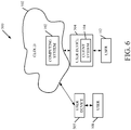
- FIG. 6 is a block diagram of architecture 100, shown in FIG. 1 , except that its elements are disposed in a cloud computing architecture 500.
- Cloud computing provides computation, software, data access, and storage services that do not require end-user knowledge of the physical location or configuration of the system that delivers the services.
- cloud computing delivers the services over a wide area network, such as the internet, using appropriate protocols.
- cloud computing providers deliver applications over a wide area network and they can be accessed through a web browser or any other computing component.
- Software or components of architecture 100 as well as the corresponding data can be stored on servers at a remote location.
- the computing resources in a cloud computing environment can be consolidated at a remote data center location or they can be dispersed.
- Cloud computing infrastructures can deliver services through shared data centers, even though they appear as a single point of access for the user.
- the components and functions described herein can be provided from a service provider at a remote location using a cloud computing architecture.
- they can be provided from a conventional server, or they can be installed on client devices directly, or in other ways.
- Cloud computing both public and private provides substantially seamless pooling of resources, as well as a reduced need to manage and configure underlying hardware infrastructure.
- a public cloud is managed by a vendor and typically supports multiple consumers using the same infrastructure. Also, a public cloud, as opposed to a private cloud, can free up the end users from managing the hardware.
- a private cloud may be managed by the organization itself and the infrastructure is typically not shared with other organizations. The organization still maintains the hardware to some extent, such as installations and repairs, etc.
- FIG. 6 specifically shows that computing system 102 can be located in cloud 502 (which can be public, private, or a combination where portions are public while others are private). Therefore, users 108 and 112 can use user devices 504 and 505 to access those systems through cloud 502.
- cloud 502 which can be public, private, or a combination where portions are public while others are private. Therefore, users 108 and 112 can use user devices 504 and 505 to access those systems through cloud 502.
- devices 504 and 505 can be accessed directly by devices 504 and 505, through a network (either a wide area network or a local area network), they can be hosted at a remote site by a service, or they can be provided as a service through a cloud or accessed by a connection service that resides in the cloud. All of these architectures are contemplated herein.
- architecture 100 can be disposed on a wide variety of different devices. Some of those devices include servers, desktop computers, laptop computers, tablet computers, or other mobile devices, such as palm top computers, cell phones, smart phones, multimedia players, personal digital assistants, etc.
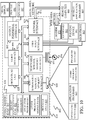
- FIG. 7 is a simplified block diagram of one illustrative example of a handheld or mobile computing device that can be used as a user's or client's hand held device 16, in which the present system (or parts of it) can be deployed.
- Figures 8-9 are examples of handheld or mobile devices.
- FIG. 7 provides a general block diagram of the components of a client device 16 that can run components of architecture 100 or that interacts with architecture 100, or both.
- a communications link 13 is provided that allows the handheld device to communicate with other computing devices and under some embodiments provides a channel for receiving information automatically, such as by scanning.
- Examples of communications link 13 include an infrared port, a serial/USB port, a cable network port such as an Ethernet port, and a wireless network port allowing communication though one or more communication protocols including General Packet Radio Service (GPRS), LTE, HSPA, HSPA+ and other 3G and 4G radio protocols, 1Xrtt, and Short Message Service, which are wireless services used to provide cellular access to a network, as well as Wi-Fi protocols, and Bluetooth protocol, which provide local wireless connections to networks.
- GPRS General Packet Radio Service
- LTE Long Term Evolution
- HSPA High Speed Packet Access
- HSPA+ High Speed Packet Access Plus
- 3G and 4G radio protocols 3G and 4G radio protocols
- 1Xrtt 3G and 4G radio protocols
- Short Message Service Short Message Service
- SD card interface 15 and communication links 13 communicate with a processor 17 (which can also embody processors from previous Figures) along a bus 19 that is also connected to memory 21 and input/output (I/O) components 23, as well as clock 25 and location system 27.
- processor 17 which can also embody processors from previous Figures
- bus 19 that is also connected to memory 21 and input/output (I/O) components 23, as well as clock 25 and location system 27.
- I/O components 23 are provided to facilitate input and output operations.
- I/O components 23 for various embodiments of the device 16 can include input components such as buttons, touch sensors, multi-touch sensors, optical or video sensors, voice sensors, touch screens, proximity sensors, microphones, tilt sensors, and gravity switches and output components such as a display device, a speaker, and or a printer port.
- Other I/O components 23 can be used as well.
- Clock 25 illustratively comprises a real time clock component that outputs a time and date. It can also, illustratively, provide timing functions for processor 17.
- Location system 27 illustratively includes a component that outputs a current geographical location of device 16. This can include, for instance, a global positioning system (GPS) receiver, a LORAN system, a dead reckoning system, a cellular triangulation system, or other positioning system. It can also include, for example, mapping software or navigation software that generates desired maps, navigation routes and other geographic functions.
- GPS global positioning system
- Memory 21 stores operating system 29, network settings 31, applications 33, application configuration settings 35, data store 37, communication drivers 39, and communication configuration settings 41.
- Memory 21 can include all types of tangible volatile and non-volatile computer-readable memory devices. It can also include computer storage media (described below).
- Memory 21 stores computer readable instructions that, when executed by processor 17, cause the processor to perform computer-implemented steps or functions according to the instructions.
- device 16 can have a client system 24 which can run various business applications or embody parts or all of client system 104. Processor 17 can be activated by other components to facilitate their functionality as well.
- Examples of the network settings 31 include things such as proxy information, Internet connection information, and mappings.
- Application configuration settings 35 include settings that tailor the application for a specific enterprise or user.
- Communication configuration settings 41 provide parameters for communicating with other computers and include items such as GPRS parameters, SMS parameters, connection user names and passwords.
- Applications 33 can be applications that have previously been stored on the device 16 or applications that are installed during use, although these can be part of operating system 29, or hosted external to device 16, as well.
- FIG. 8 shows one example in which device 16 is a tablet computer 600.
- computer 600 is shown with user interface display screen 602.
- Screen 602 can be a touch screen (so touch gestures from a user's finger can be used to interact with the application) or a pen-enabled interface that receives inputs from a pen or stylus. It can also use an on-screen virtual keyboard. Of course, it might also be attached to a keyboard or other user input device through a suitable attachment mechanism, such as a wireless link or USB port, for instance.
- Computer 600 can also illustratively receive voice inputs as well.
- FIG. 9 shows that the device can be a smart phone 71.
- Smart phone 71 has a touch sensitive display 73 that displays icons or tiles or other user input mechanisms 75. Mechanisms 75 can be used by a user to run applications, make calls, perform data transfer operations, etc.
- smart phone 71 is built on a mobile operating system and offers more advanced computing capability and connectivity than a feature phone.
- FIG. 10 is one example of a computing environment in which architecture 100, or parts of it, (for example) can be deployed.
- an example system for implementing some embodiments includes a general-purpose computing device in the form of a computer 810.
- Components of computer 810 may include, but are not limited to, a processing unit 820 (which can comprise processors from previous Figures), a system memory 830, and a system bus 821 that couples various system components including the system memory to the processing unit 820.
- the system bus 821 may be any of several types of bus structures including a memory bus or memory controller, a peripheral bus, and a local bus using any of a variety of bus architectures.
- such architectures include Industry Standard Architecture (ISA) bus, Micro Channel Architecture (MCA) bus, Enhanced ISA (EISA) bus, Video Electronics Standards Association (VESA) local bus, and Peripheral Component Interconnect (PCI) bus also known as Mezzanine bus.
- ISA Industry Standard Architecture
- MCA Micro Channel Architecture
- EISA Enhanced ISA
- VESA Video Electronics Standards Association
- PCI Peripheral Component Interconnect
- Computer 810 typically includes a variety of computer readable media.
- Computer readable media can be any available media that can be accessed by computer 810 and includes both volatile and nonvolatile media, removable and non-removable media.
- Computer readable media may comprise computer storage media and communication media.
- Computer storage media is different from, and does not include, a modulated data signal or carrier wave. It includes hardware storage media including both volatile and nonvolatile, removable and non-removable media implemented in any method or technology for storage of information such as computer readable instructions, data structures, program modules or other data.
- Computer storage media includes, but is not limited to, RAM, ROM, EEPROM, flash memory or other memory technology, CD-ROM, digital versatile disks (DVD) or other optical disk storage, magnetic cassettes, magnetic tape, magnetic disk storage or other magnetic storage devices, or any other medium which can be used to store the desired information and which can be accessed by computer 810.
- Communication media typically embodies computer readable instructions, data structures, program modules or other data in a transport mechanism and includes any information delivery media.
- modulated data signal means a signal that has one or more of its characteristics set or changed in such a manner as to encode information in the signal.
- communication media includes wired media such as a wired network or direct-wired connection, and wireless media such as acoustic, RF, infrared and other wireless media. Combinations of any of the above should also be included within the scope of computer readable media.
- the system memory 830 includes computer storage media in the form of volatile and/or non-volatile memory such as read only memory (ROM) 831 and random access memory (RAM) 832.
- ROM read only memory
- RAM random access memory
- BIOS basic input/output system 833
- RAM 832 typically contains data and/or program modules that are immediately accessible to and/or presently being operated on by processing unit 820.
- FIG. 10 illustrates operating system 834, application programs 835, other program modules 836, and program data 837.
- the computer 810 may also include other removable/non-removable volatile/nonvolatile computer storage media.
- FIG. 10 illustrates a hard disk drive 841 that reads from or writes to non-removable, nonvolatile magnetic media, and an optical disk drive 855 that reads from or writes to a removable, nonvolatile optical disk 856 such as a CD ROM or other optical media.
- Other removable/non-removable, volatile/nonvolatile computer storage media that can be used in the exemplary operating environment include, but are not limited to, magnetic tape cassettes, flash memory cards, digital versatile disks, digital video tape, solid state RAM, solid state ROM, and the like.
- the hard disk drive 841 is typically connected to the system bus 821 through a non-removable memory interface such as interface 840, and optical disk drive 855 are typically connected to the system bus 821 by a removable memory interface, such as interface 850.
- the functionality described herein can be performed, at least in part, by one or more hardware logic components.
- illustrative types of hardware logic components include Field-programmable Gate Arrays (FPGAs), Program-specific Integrated Circuits (ASICs), Program-specific Standard Products (ASSPs), System-on-a-chip systems (SOCs), Complex Programmable Logic Devices (CPLDs), etc.
- hard disk drive 841 is illustrated as storing operating system 844, application programs 845, other program modules 846, and program data 847. Note that these components can either be the same as or different from operating system 834, application programs 835, other program modules 836, and program data 837. Operating system 844, application programs 845, other program modules 846, and program data 847 are given different numbers here to illustrate that, at a minimum, they are different copies.
- a user may enter commands and information into the computer 810 through input devices such as a keyboard 862, a microphone 863, and a pointing device 861, such as a mouse, trackball or touch pad.
- Other input devices may include a joystick, game pad, satellite dish, scanner, or the like.
- These and other input devices are often connected to the processing unit 820 through a user input interface 860 that is coupled to the system bus, but may be connected by other interface and bus structures, such as a parallel port, game port or a universal serial bus (USB).
- a visual display 891 or other type of display device is also connected to the system bus 821 via an interface, such as a video interface 890.
- computers may also include other peripheral output devices such as speakers 897 and printer 896, which may be connected through an output peripheral interface 895.
- the computer 810 is operated in a networked environment using logical connections to one or more remote computers, such as a remote computer 880.
- the remote computer 880 may be a personal computer, a hand-held device, a server, a router, a network PC, a peer device or other common network node, and typically includes many or all of the elements described above relative to the computer 810.
- the logical connections depicted in FIG. 10 include a local area network (LAN) 871 and a wide area network (WAN) 873, but may also include other networks.
- LAN local area network
- WAN wide area network
- Such networking environments are commonplace in offices, enterprise-wide computer networks, intranets and the Internet.
- the computer 810 When used in a LAN networking environment, the computer 810 is connected to the LAN 871 through a network interface or adapter 870. When used in a WAN networking environment, the computer 810 typically includes a modem 872 or other means for establishing communications over the WAN 873, such as the Internet.
- the modem 872 which may be internal or external, may be connected to the system bus 821 via the user input interface 860, or other appropriate mechanism.
- program modules depicted relative to the computer 810, or portions thereof may be stored in the remote memory storage device.
- FIG. 10 illustrates remote application programs 885 as residing on remote computer 880. It will be appreciated that the network connections shown are exemplary and other means of establishing a communications link between the computers may be used.
Landscapes
- Engineering & Computer Science (AREA)
- Software Systems (AREA)
- Theoretical Computer Science (AREA)
- Physics & Mathematics (AREA)
- General Engineering & Computer Science (AREA)
- General Physics & Mathematics (AREA)
- Human Computer Interaction (AREA)
- Computer Networks & Wireless Communication (AREA)
- Signal Processing (AREA)
- Quality & Reliability (AREA)
- Data Mining & Analysis (AREA)
- Stored Programmes (AREA)
- Debugging And Monitoring (AREA)
- User Interface Of Digital Computer (AREA)
- Computer And Data Communications (AREA)
Description
- There are a wide variety of different types of computing systems. Some computing systems are used by organizations that perform customer service or contact center operations. In such systems, a hosting application shows multi-dimensional information on a single user interface from various external applications (or external processes).
- Some such systems provide the ability to configure a single user interface that combines user interfaces from various external applications (or external processes) that can be hosted within the hosting application (or parent) user interface. However, the external applications (or external processes) can crash or otherwise become nonresponsive. Because the hosting application renders different user interfaces from the different processes to create the unified view, and because the hosting application has little or no control over the external applications (or processes), the external applications (or processes) can cause the hosting application, itself, to crash or become nonresponsive. This can essentially block the entire hosting application, since all of the user interfaces are rendered on a single UI thread that belongs to the hosting application. From
US 6170019 , a device for operating an apparatus is known that includes a server, a central monitoring module, an apparatus for communicating between the server and the monitoring module, a plurality of control, maintainance and/or monitoring programs and an apparatus for communicating between the control, maintenance and/or monitoring programs on the one hand as well the server and/or the monitoring module on the other hand. A browser can be connected to the device so that a system for the operation of the apparatus derives therefrom. A user interface with security-related functions or interactive functions can be realized easily and with little programming outlay. - The discussion above is merely provided for general background information and is not intended to be used as an aid in determining the scope of the claimed subject matter.
- The invention is defined by the appended claims.
- User interfaces for multiple external processes are hosted in a single user interface (UI) threaded host application. A broker process (or broker window) is created in the hosting application for each external process user interface window. A monitor monitors the state of the hosting application and, if it becomes nonresponsive, identifies each of the external processes that are nonresponsive, and issues a notification to terminate the identified external processes.
- This Summary is provided to introduce a selection of concepts in a simplified form that are further described below in the Detailed Description. This Summary is not intended to identify key features or essential features of the claimed subject matter, nor is it intended to be used as an aid in determining the scope of the claimed subject matter. The claimed subject matter is not limited to implementations that solve any or all disadvantages noted in the background.
-
-
FIG. 1 is a block diagram of one example of a computing system architecture. -
FIG. 2 is a block diagram illustrating arrangement of hierarchically arranged process user interfaces. -
FIG. 3 is a flow diagram illustrating one example of the operation of a monitoring system (shown inFIG. 1 ) in generating an external process monitor list. -
FIG. 4 is a block diagram showing one example of a nonresponding external process identifier component, in more detail. -
FIG. 5 is a flow diagram illustrating one example of the operation of a monitoring system (shown inFIG. 1 ) in identifying child processes that are in a non-responsive state. -
FIG. 6 shows one example of the architecture illustrated inFIG. 1 , deployed in a cloud computing architecture. -
FIGS. 7-9 show various examples of mobile devices. -
FIG. 10 is a block diagram of one example of a computing environment that can be used in the architecture shown in the previous figures. -
FIG. 1 is a block diagram of one example of acomputing system architecture 100.Architecture 100 illustratively includescomputing system 102 and one ormore client systems 104.FIG. 1 shows that, in one example,computing system 102 illustratively generatesuser interfaces 106 for interaction byuser 108.User 108 can illustratively interact withuser interfaces 106 to control and manipulatecomputing system 102. Similarly,client system 104 illustratively generatesuser interfaces 110 for interaction byuser 112.User 112 can illustratively interact withuser interfaces 110 in order to control and manipulateclient system 104. - In the example shown in
FIG. 1 ,computing system 102 illustratively includes one or more processors orservers 114, operating system 116 (which can include amessage handling logic 118 and other operating system functionality 120),data store 122,user interface component 124, external process user interface (UI)hosting system 126, and it can includeother items 128. Also, in the example shown inFIG. 1 , external processUI hosting system 126 can include a set ofhosting functionality 130,isolation system 132,monitoring system 134, and it can includeother items 136.FIG. 1 also shows thatclient system 104 illustratively includes one ormore client components 162, one ormore processors 164,user interface component 166 anddata store 168. It can includeother client functionality 170 as well. -
Hosting functionality 130 illustratively hosts user interfaces for various external processes (such as processes that can be run on client system 104).Isolation system 132 illustratively isolates those user interfaces, andmonitoring system 134 monitors thehosting functionality 130 as well as the external processes, to determine whether they are in a nonresponsive state. This is described in greater detail below. -
Isolation system 132, itself, includes brokerprocess generation logic 138, new processdetails notification logic 140, attachment/detachment logic 142, and it can includeother items 144.Monitoring system 134, itself, illustratively includes childprocess identifier logic 146, monitorlist generator logic 148, hostsystem monitor logic 150, non-responding externalprocess identifier logic 152, monitor data store 154 (which can include externalprocess monitor list 156, and other items 158), and it can includeother items 160. - Before describing the operation of
computing system 102 in more detail, a brief overview will first be provided. External processUI hosting system 126 illustratively hosts the user interface(s) of multiple external processes (which can be run, for instance, on client system 104) inside a tabbed layout in a single user interface threaded application which can be run byhosting functionality 130. In doing so,isolation system 132 illustratively generates a broker process for each external process user interface (or window) that is hosted.Monitoring system 134 monitors the hosting application to identify whether it enters a non-responsive state. If so, it iterates through all of the hosted, external processes, to identify which of those is in a nonresponsive state. It then identifies, toisolation system 132, which of the external processes are nonresponsive, andisolation system 132 can terminate the broker process that is managing that external process. This type of isolation and monitoring enables the main hosting application run byhosting functionality 130 to maintain access to all of the other external processes, without becoming nonresponsive, based upon one or more of the external processes, themselves, being nonresponsive. -
FIG. 2 is a block diagram illustrating one example of amain hosting process 171 that can be run by a main hosting application that hosts user interfaces for a set ofexternal processes main hosting process 171 includes a hostprocess user interface 178. It also includes a separate broker process window (or broker process user interface) 180, 182 and 184, corresponding to each of the external processes 172-176.Hosting process 171 is also illustratively coupled to, and managing, the interfaces for acommunication channel 186 that provides communication with monitoring system 134 (shown inFIG. 1 ). - By way of overview, when the host
process user interface 178 becomes nonresponsive (as detected by monitoring system 134), then monitoringsystem 134 illustratively accesses each of the broker process user interfaces (or windows) 180-184 to determine which (if any) external processes 172-176 have become nonresponsive. It can then send a message to messagehandling component 118 inoperating system 116 to indicate that the corresponding broker process window 180-184 should be terminated (or detached) from hostprocess user interface 178. The hostprocess user interface 178 can then terminate the corresponding broker process windows 180-184, while maintaining its connection to the other broker process windows 180-184 (and therefore maintaining accessibility to the other external processes that are still responsive). When the external process that was identified as being in a nonresponsive state is then returned to its responsive state, the broker process window (or a new broker process window) for that external process can be generated and reattached to the hostprocess user interface 178. -
FIG. 3 is a flow diagram illustrating one example of the operation of externalUI hosting system 126 in identifying new process user interfaces that it will be hosting, and communicating that information to monitoringsystem 134 so thatmonitoring system 134 can enter it in externalprocess monitor list 156. It is fist assumed that the main external process hosting application is started. This can be started, for instance, inhosting functionality 130. This is indicated byblock 200 inFIG. 3 . - When that is detected, the hosting application (or another set of logic or component) spawns an instance of a monitoring process that can be implemented by monitoring
system 134. Spawning the monitoring process is indicated byblock 202. At some point, the main external process hosting application will begin to host user interfaces for external processes. When it does this, attachment/detachment logic 142 controls brokerprocess generation logic 138 to generate a broker process (which has a broker process window) for the new external process to be hosted. This is so the hostingapplication 130 can detach itself from the corresponding external process (should it become non-responsive) by terminating its corresponding broker process. New processdetails notification logic 140 then notifiesmonitoring system 134 of the details of the new process, for which a user interface is to be hosted by the main process hosting application. Notifying themonitoring system 134 of the new process details is indicated byblock 204 inFIG. 3 . - Child
process identifier logic 146 then locates the new process, based upon the details that have been provided. This is indicated byblock 206. Monitorlist generator logic 148 then determines whether the new process has one or more child processes. This is indicated byblock 206. If so, then childprocess identifier logic 146 identifies the details of each of the child processes. This is indicated byblock 210. - Monitor
list generator logic 148 then adds the new process (and any of its child processes) into the externalprocess monitor list 156. This is indicated byblock 212. - This continues, for each new external process that is being hosted by the main external process hosting application. This is indicated by
block 214. - Once
monitoring system 134 has items in its externalprocess monitor list 156, it can begin monitoring the main external process hosting application, as well as the external processes. Briefly, host system monitorlogic 150 monitors the main external process hosting application to determine whether it has become nonresponsive, and non-responding externalprocess identifier logic 152 identifies which, if any, of the external processes have caused the main hosting application to become nonresponsive, so their broker processes can be terminated. This is now described in greater detail below with respect toFIGS. 4 and5 . -
FIG. 4 is a block diagram showing one example of non-responding externalprocess identifier logic 152 in more detail. In the example shown inFIG. 4 ,logic 152 includes childprocess accessing logic 220, childprocess iteration logic 222,responsiveness identifier logic 224,termination notifier logic 226, and it can includeother items 228. By way of overview, childprocess accessing logic 220 identifies various child processes that are having their UIs hosted by the main hosting application. Childprocess iteration logic 222 iterates through each of the child process UIs, andresponsiveness identifier logic 224 identifies which of them, if any, have become nonresponsive.Termination notifier logic 226 then sends a notification indicating that the broker processes for the nonresponsive external process UIs should be terminated. -
FIG. 5 is a flow diagram illustrating one example of the operation ofmonitoring system 134, in identifying nonresponsive processes, in more detail. - At some point, host
system monitoring logic 150 determines whether it is time to monitor the main hosting application to determine whether it has become nonresponsive. This can be done in a wide variety of different ways. In one example, host system monitorlogic 150 continuously polls the main hosting application to ensure that it is still responsive. In another example, it can poll the main hosting application intermittently, periodically, or based on other triggering criteria. All of these are contemplated herein. Determining that it is time to monitor the main hosting application is indicated byblock 250 inFIG. 5 . - When it is time to monitor the main hosting application, host system monitor
logic 150 checks to determine whether it is responsive. This is indicated byblock 252. For instance, it can monitor the activity of the main hosting application for a configurable amount of time. This is indicated byblock 254. It can send various different types of messages to the hosting application to determine whether it is responsive or nonresponsive. This is indicated byblock 256. It can identify the state of responsiveness of the main hosting application in other ways as well, and this is indicated byblock 258. - If host
system monitoring logic 150 determines that the main hosting application is nonresponsive (as indicated by block 260), then non-responding externalprocess identifier logic 152 begins to determine which, if any, of the processes in the externalprocess monitor list 156 have become nonresponsive. Thus, childprocess accessing logic 220 first selects a process from the monitor list, andresponsiveness identifier logic 224 determines whether the selected process is responding. This is indicated byblocks FIG. 5 . - If the selected process is not responding, then
responsiveness identifier logic 224 notifies the main hosting application of the details of the selected process, and also indicating that it is nonresponsive. This is indicated byblock 266. This can allow the main hosting application to perform certain activities. For instance, it may wish to log the state of the external process, or various details about the external process, before the external process is terminated. - In one example,
responsiveness identifier logic 224 can also determine whether the selected process responded during the previous monitoring cycle. This is indicated byblock 268. If so, it may wait to send (or delay in sending) a termination notification for the selected process, allowing the selected process to recover, if possible. - However, if the selected process has not been responsive for multiple cycles, then
termination notifier logic 226 illustratively sendsmessage handling logic 118 in operating system 116 a message or notification that the broker process corresponding to the selected, nonresponsive process, should be terminated. This is indicated byblock 270. Themessage handling system 118 can communicate this message to the main hosting application which, at its discretion, can then terminate the broker process for the nonresponsive external process. - Child
process iteration logic 222 iterates through all of the external processes in the externalprocess monitor list 156, until all of them have been checked for responsiveness. This is indicated byblock 272 inFIG. 5 . - It can thus be seen that the external processes that have user interfaces hosted by the main hosting application are isolated. This is done by generating a broker process corresponding to each of the external processes. Because the broker process is generated within the main hosting application, the main hosting application can detach itself from any external processes that become nonresponsive. However, it can maintain an attachment with other external processes that are still responding.
- Similarly, the monitoring system first monitors the main hosting application to identify when it has become nonresponsive, itself. When this happens, the monitoring system iterates through all of the external processes that have user interfaces hosted by the main hosting application, and identifies which of those, if any, have become nonresponsive. It can then issue a notification to terminate the corresponding broker processes so that the main hosting application does not stay in a nonresponsive state, but instead can continue operating with respect to the other external processes.
- It will be noted that the above discussion has described a variety of different systems, components and/or logic. It will be appreciated that such systems, components and/or logic can be comprised of hardware items (such as processors and associated memory, or other processing components, some of which are described below) that perform the functions associated with those systems, components and/or logic. In addition, the systems, components and/or logic can be comprised of software that is loaded into a memory and is subsequently executed by a processor or server, or other computing component, as described below. The systems, components and/or logic can also be comprised of different combinations of hardware, software, firmware, etc., some examples of which are described below. These are only some examples of different structures that can be used to form the systems, components and/or logic described above. Other structures can be used as well.
- The present discussion has mentioned processors and servers. In one embodiment, the processors and servers include computer processors with associated memory and timing circuitry, not separately shown. They are functional parts of the systems or devices to which they belong and are activated by, and facilitate the functionality of the other components or items in those systems.
- Also, a number of user interface displays have been discussed. They can take a wide variety of different forms and can have a wide variety of different user actuatable input mechanisms disposed thereon. For instance, the user actuatable input mechanisms can be text boxes, check boxes, icons, links, drop-down menus, search boxes, etc. They can also be actuated in a wide variety of different ways. For instance, they can be actuated using a point and click device (such as a track ball or mouse). They can be actuated using hardware buttons, switches, a joystick or keyboard, thumb switches or thumb pads, etc. They can also be actuated using a virtual keyboard or other virtual actuators. In addition, where the screen on which they are displayed is a touch sensitive screen, they can be actuated using touch gestures. Also, where the device that displays them has speech recognition components, they can be actuated using speech commands.
- A number of data stores have also been discussed. It will be noted they can each be broken into multiple data stores. All can be local to the systems accessing them, all can be remote, or some can be local while others are remote. All of these configurations are contemplated herein.
- Also, the figures show a number of blocks with functionality ascribed to each block. It will be noted that fewer blocks can be used so the functionality is performed by fewer components. Also, more blocks can be used with the functionality distributed among more components.
-
FIG. 6 is a block diagram ofarchitecture 100, shown inFIG. 1 , except that its elements are disposed in acloud computing architecture 500. Cloud computing provides computation, software, data access, and storage services that do not require end-user knowledge of the physical location or configuration of the system that delivers the services. In various embodiments, cloud computing delivers the services over a wide area network, such as the internet, using appropriate protocols. For instance, cloud computing providers deliver applications over a wide area network and they can be accessed through a web browser or any other computing component. Software or components ofarchitecture 100 as well as the corresponding data, can be stored on servers at a remote location. The computing resources in a cloud computing environment can be consolidated at a remote data center location or they can be dispersed. Cloud computing infrastructures can deliver services through shared data centers, even though they appear as a single point of access for the user. Thus, the components and functions described herein can be provided from a service provider at a remote location using a cloud computing architecture. Alternatively, they can be provided from a conventional server, or they can be installed on client devices directly, or in other ways. - The description is intended to include both public cloud computing and private cloud computing. Cloud computing (both public and private) provides substantially seamless pooling of resources, as well as a reduced need to manage and configure underlying hardware infrastructure.
- A public cloud is managed by a vendor and typically supports multiple consumers using the same infrastructure. Also, a public cloud, as opposed to a private cloud, can free up the end users from managing the hardware. A private cloud may be managed by the organization itself and the infrastructure is typically not shared with other organizations. The organization still maintains the hardware to some extent, such as installations and repairs, etc.
- In the example shown in
FIG. 6 , some items are similar to those shown inFIG. 1 and they are similarly numbered.FIG. 6 specifically shows thatcomputing system 102 can be located in cloud 502 (which can be public, private, or a combination where portions are public while others are private). Therefore,users user devices cloud 502. - Regardless of where they are located, they can be accessed directly by
devices - It will also be noted that
architecture 100, or portions of it, can be disposed on a wide variety of different devices. Some of those devices include servers, desktop computers, laptop computers, tablet computers, or other mobile devices, such as palm top computers, cell phones, smart phones, multimedia players, personal digital assistants, etc. -
FIG. 7 is a simplified block diagram of one illustrative example of a handheld or mobile computing device that can be used as a user's or client's hand helddevice 16, in which the present system (or parts of it) can be deployed.Figures 8-9 are examples of handheld or mobile devices. -
FIG. 7 provides a general block diagram of the components of aclient device 16 that can run components ofarchitecture 100 or that interacts witharchitecture 100, or both. In thedevice 16, acommunications link 13 is provided that allows the handheld device to communicate with other computing devices and under some embodiments provides a channel for receiving information automatically, such as by scanning. Examples of communications link 13 include an infrared port, a serial/USB port, a cable network port such as an Ethernet port, and a wireless network port allowing communication though one or more communication protocols including General Packet Radio Service (GPRS), LTE, HSPA, HSPA+ and other 3G and 4G radio protocols, 1Xrtt, and Short Message Service, which are wireless services used to provide cellular access to a network, as well as Wi-Fi protocols, and Bluetooth protocol, which provide local wireless connections to networks. - In other examples, applications or systems are received on a removable Secure Digital (SD) card that is connected to a
SD card interface 15.SD card interface 15 andcommunication links 13 communicate with a processor 17 (which can also embody processors from previous Figures) along abus 19 that is also connected tomemory 21 and input/output (I/O)components 23, as well asclock 25 andlocation system 27. - I/
O components 23, in one embodiment, are provided to facilitate input and output operations. I/O components 23 for various embodiments of thedevice 16 can include input components such as buttons, touch sensors, multi-touch sensors, optical or video sensors, voice sensors, touch screens, proximity sensors, microphones, tilt sensors, and gravity switches and output components such as a display device, a speaker, and or a printer port. Other I/O components 23 can be used as well. -
Clock 25 illustratively comprises a real time clock component that outputs a time and date. It can also, illustratively, provide timing functions forprocessor 17. -
Location system 27 illustratively includes a component that outputs a current geographical location ofdevice 16. This can include, for instance, a global positioning system (GPS) receiver, a LORAN system, a dead reckoning system, a cellular triangulation system, or other positioning system. It can also include, for example, mapping software or navigation software that generates desired maps, navigation routes and other geographic functions. -
Memory 21stores operating system 29,network settings 31,applications 33,application configuration settings 35,data store 37,communication drivers 39, and communication configuration settings 41.Memory 21 can include all types of tangible volatile and non-volatile computer-readable memory devices. It can also include computer storage media (described below).Memory 21 stores computer readable instructions that, when executed byprocessor 17, cause the processor to perform computer-implemented steps or functions according to the instructions. Similarly,device 16 can have aclient system 24 which can run various business applications or embody parts or all ofclient system 104.Processor 17 can be activated by other components to facilitate their functionality as well. - Examples of the
network settings 31 include things such as proxy information, Internet connection information, and mappings.Application configuration settings 35 include settings that tailor the application for a specific enterprise or user. Communication configuration settings 41 provide parameters for communicating with other computers and include items such as GPRS parameters, SMS parameters, connection user names and passwords. -
Applications 33 can be applications that have previously been stored on thedevice 16 or applications that are installed during use, although these can be part ofoperating system 29, or hosted external todevice 16, as well. -
FIG. 8 shows one example in whichdevice 16 is atablet computer 600. InFIG. 8 ,computer 600 is shown with userinterface display screen 602.Screen 602 can be a touch screen (so touch gestures from a user's finger can be used to interact with the application) or a pen-enabled interface that receives inputs from a pen or stylus. It can also use an on-screen virtual keyboard. Of course, it might also be attached to a keyboard or other user input device through a suitable attachment mechanism, such as a wireless link or USB port, for instance.Computer 600 can also illustratively receive voice inputs as well. -
FIG. 9 shows that the device can be asmart phone 71.Smart phone 71 has a touchsensitive display 73 that displays icons or tiles or otheruser input mechanisms 75.Mechanisms 75 can be used by a user to run applications, make calls, perform data transfer operations, etc. In general,smart phone 71 is built on a mobile operating system and offers more advanced computing capability and connectivity than a feature phone. - Note that other forms of the
devices 16 are possible. -
FIG. 10 is one example of a computing environment in whicharchitecture 100, or parts of it, (for example) can be deployed. With reference toFIG. 10 , an example system for implementing some embodiments includes a general-purpose computing device in the form of acomputer 810. Components ofcomputer 810 may include, but are not limited to, a processing unit 820 (which can comprise processors from previous Figures), asystem memory 830, and asystem bus 821 that couples various system components including the system memory to theprocessing unit 820. Thesystem bus 821 may be any of several types of bus structures including a memory bus or memory controller, a peripheral bus, and a local bus using any of a variety of bus architectures. By way of example, and not limitation, such architectures include Industry Standard Architecture (ISA) bus, Micro Channel Architecture (MCA) bus, Enhanced ISA (EISA) bus, Video Electronics Standards Association (VESA) local bus, and Peripheral Component Interconnect (PCI) bus also known as Mezzanine bus. Memory and programs described with respect toFIG. 1 can be deployed in corresponding portions ofFIG. 10 . -
Computer 810 typically includes a variety of computer readable media. Computer readable media can be any available media that can be accessed bycomputer 810 and includes both volatile and nonvolatile media, removable and non-removable media. By way of example, and not limitation, computer readable media may comprise computer storage media and communication media. Computer storage media is different from, and does not include, a modulated data signal or carrier wave. It includes hardware storage media including both volatile and nonvolatile, removable and non-removable media implemented in any method or technology for storage of information such as computer readable instructions, data structures, program modules or other data. Computer storage media includes, but is not limited to, RAM, ROM, EEPROM, flash memory or other memory technology, CD-ROM, digital versatile disks (DVD) or other optical disk storage, magnetic cassettes, magnetic tape, magnetic disk storage or other magnetic storage devices, or any other medium which can be used to store the desired information and which can be accessed bycomputer 810. Communication media typically embodies computer readable instructions, data structures, program modules or other data in a transport mechanism and includes any information delivery media. The term "modulated data signal" means a signal that has one or more of its characteristics set or changed in such a manner as to encode information in the signal. By way of example, and not limitation, communication media includes wired media such as a wired network or direct-wired connection, and wireless media such as acoustic, RF, infrared and other wireless media. Combinations of any of the above should also be included within the scope of computer readable media. - The
system memory 830 includes computer storage media in the form of volatile and/or non-volatile memory such as read only memory (ROM) 831 and random access memory (RAM) 832. A basic input/output system 833 (BIOS), containing the basic routines that help to transfer information between elements withincomputer 810, such as during start-up, is typically stored inROM 831.RAM 832 typically contains data and/or program modules that are immediately accessible to and/or presently being operated on by processingunit 820. By way of example, and not limitation,FIG. 10 illustratesoperating system 834,application programs 835,other program modules 836, andprogram data 837. - The
computer 810 may also include other removable/non-removable volatile/nonvolatile computer storage media. By way of example only,FIG. 10 illustrates ahard disk drive 841 that reads from or writes to non-removable, nonvolatile magnetic media, and anoptical disk drive 855 that reads from or writes to a removable, nonvolatileoptical disk 856 such as a CD ROM or other optical media. Other removable/non-removable, volatile/nonvolatile computer storage media that can be used in the exemplary operating environment include, but are not limited to, magnetic tape cassettes, flash memory cards, digital versatile disks, digital video tape, solid state RAM, solid state ROM, and the like. Thehard disk drive 841 is typically connected to thesystem bus 821 through a non-removable memory interface such asinterface 840, andoptical disk drive 855 are typically connected to thesystem bus 821 by a removable memory interface, such asinterface 850. - Alternatively, or in addition, the functionality described herein can be performed, at least in part, by one or more hardware logic components. For example, and without limitation, illustrative types of hardware logic components that can be used include Field-programmable Gate Arrays (FPGAs), Program-specific Integrated Circuits (ASICs), Program-specific Standard Products (ASSPs), System-on-a-chip systems (SOCs), Complex Programmable Logic Devices (CPLDs), etc.
- The drives and their associated computer storage media discussed above and illustrated in
FIG. 10 , provide storage of computer readable instructions, data structures, program modules and other data for thecomputer 810. InFIG. 10 , for example,hard disk drive 841 is illustrated as storingoperating system 844,application programs 845,other program modules 846, andprogram data 847. Note that these components can either be the same as or different fromoperating system 834,application programs 835,other program modules 836, andprogram data 837.Operating system 844,application programs 845,other program modules 846, andprogram data 847 are given different numbers here to illustrate that, at a minimum, they are different copies. - A user may enter commands and information into the
computer 810 through input devices such as akeyboard 862, amicrophone 863, and apointing device 861, such as a mouse, trackball or touch pad. Other input devices (not shown) may include a joystick, game pad, satellite dish, scanner, or the like. These and other input devices are often connected to theprocessing unit 820 through auser input interface 860 that is coupled to the system bus, but may be connected by other interface and bus structures, such as a parallel port, game port or a universal serial bus (USB). Avisual display 891 or other type of display device is also connected to thesystem bus 821 via an interface, such as avideo interface 890. In addition to the monitor, computers may also include other peripheral output devices such asspeakers 897 andprinter 896, which may be connected through an outputperipheral interface 895. - The
computer 810 is operated in a networked environment using logical connections to one or more remote computers, such as aremote computer 880. Theremote computer 880 may be a personal computer, a hand-held device, a server, a router, a network PC, a peer device or other common network node, and typically includes many or all of the elements described above relative to thecomputer 810. The logical connections depicted inFIG. 10 include a local area network (LAN) 871 and a wide area network (WAN) 873, but may also include other networks. Such networking environments are commonplace in offices, enterprise-wide computer networks, intranets and the Internet. - When used in a LAN networking environment, the
computer 810 is connected to theLAN 871 through a network interface oradapter 870. When used in a WAN networking environment, thecomputer 810 typically includes amodem 872 or other means for establishing communications over theWAN 873, such as the Internet. Themodem 872, which may be internal or external, may be connected to thesystem bus 821 via theuser input interface 860, or other appropriate mechanism. In a networked environment, program modules depicted relative to thecomputer 810, or portions thereof, may be stored in the remote memory storage device. By way of example, and not limitation,FIG. 10 illustratesremote application programs 885 as residing onremote computer 880. It will be appreciated that the network connections shown are exemplary and other means of establishing a communications link between the computers may be used. - It should also be noted that the different embodiments described herein can be combined in different ways. That is, parts of one or more embodiments can be combined with parts of one or more other embodiments. All of this is contemplated herein.
Claims (4)
- A computing system (100), comprising:a set of hosting functionality (130) that runs a hosting application that hosts user interfaces for a plurality of external processes that are external to the computing system;an isolation system (132) that generates, for each external process, a corresponding broker process that hosts a user interface for the corresponding external process and that is controlled by the hosting application; anda monitoring system (134) that monitors a responsiveness of the hosting application and each of the external processes and generates a termination signal to terminate broker processes for non-responsive external processes;wherein the isolation system (132) comprises:broker process generation logic (138) that generates a first broker process for a corresponding first external process; andnew process details notification logic (140) that notifies the monitoring system of identifying information identifying the first external process;wherein the monitoring system (134) comprises:a monitor list generator logic (148) that adds a first external process identifier that identifies the first external process to a process monitor list based on the identifying information;characterized in that the monitoring system further comprises:a host system monitor logic (150) that monitors the responsiveness of the hosting application and generates a non-responsive output indicative of the hosting application being in a non-responsive state;non-responding external process identifier logic (152) that receives the non-responsive output indicating that the hosting application is in a non-responsive state and determines a responsiveness of one or more of the external processes identified on the process monitor list;wherein the non-responding external process identifier logic (152) comprises:responsiveness identifier logic (224) that selects an external process from the process monitor list, corresponding to the non-responsive hosting application, and identifies whether the selected external process is responsive and, if not, generates an output indicating that the selected external process is in a non-responsive state;wherein the non-responding external process identifier logic (152) comprises:termination notifier logic (226) that notifies the hosting application that the selected external process in in the non-responsive state;wherein the hosting application generates the termination signal terminating the broker process corresponding to the selected external process, in response to the selected external process being in the non-responsive state,so that the hosting application does not stay in a non-responsive state but instead can continue operating with respect to the other external processes.
- The computing system of claim 1 wherein the monitoring system (134) comprises:
child process identifier logic (146) that accesses a representation of the first external process and identifies any child processes in the first external process and accesses identifying information identifying the child processes, the monitor list generator logic (148) adding child process identifiers for each identified child process to the process monitor list. - A computer implemented method, comprising:Running (200) a hosting application that hosts user interfaces for a plurality of external processes that are external to the hosting application;generating, for each external process, a corresponding broker process that hosts a user interface for the corresponding external process and that is controlled by the hosting application;monitoring a responsiveness of the hosting application and each of the external processes; andgenerating a termination signal to terminate broker processes for non-responsive external processes;wherein generating a corresponding broker process comprises:generating a first broker process for a corresponding first external process; andgenerating a notification including identifying information identifying the first external process;characterized in that:
monitoring comprises:adding a first external process identifier that identifies the first external process to a process monitor list based on the identifying information;monitoring the responsiveness of the hosting application; andgenerating a non-responsive output indicative of the hosting application being in a non-responsive state;receiving the non-responsive output indicating that the hosting application is in a non-responsive state; anddetermining (260) a responsiveness of one or more of the external processes identified on the process monitor list;wherein determining a responsiveness of the one or more of the external processes comprises:selecting (262) an external process from the process monitor list, corresponding to the non-responsive hosting application;identifying (264) whether the selected external process is responsive; andif not, generating (266) an output indicating that the selected external process is in a non-responsive state;generating (270), with the hosting application a termination signal terminating the broker process corresponding to the selected external process, in response to the selected external process being in the non-responsive state,so that the hosting application does not stay in a non-responsive state but instead can continue operating with respect to the other external processes. - The computer implemented method of claim 3 wherein monitoring comprises:accessing a representation of the first external process;identifying (208) any child processes in the first external process;accessing (210) identifying information identifying the child processes; andadding (212) child process identifiers for each identified child process to the process monitor list.
Applications Claiming Priority (3)
| Application Number | Priority Date | Filing Date | Title |
|---|---|---|---|
| IN5060CH2015 | 2015-09-22 | ||
| US14/994,297 US10270671B2 (en) | 2015-09-22 | 2016-01-13 | External process user interface isolation and monitoring |
| PCT/US2016/051800 WO2017053156A1 (en) | 2015-09-22 | 2016-09-15 | External process user interface isolation and monitoring |
Publications (2)
| Publication Number | Publication Date |
|---|---|
| EP3353647A1 EP3353647A1 (en) | 2018-08-01 |
| EP3353647B1 true EP3353647B1 (en) | 2020-07-08 |
Family
ID=58283425
Family Applications (1)
| Application Number | Title | Priority Date | Filing Date |
|---|---|---|---|
| EP16778927.0A Active EP3353647B1 (en) | 2015-09-22 | 2016-09-15 | External process user interface isolation and monitoring |
Country Status (4)
| Country | Link |
|---|---|
| US (1) | US10270671B2 (en) |
| EP (1) | EP3353647B1 (en) |
| CN (1) | CN108139919B (en) |
| WO (1) | WO2017053156A1 (en) |
Families Citing this family (2)
| Publication number | Priority date | Publication date | Assignee | Title |
|---|---|---|---|---|
| CN110673918B (en) * | 2019-09-27 | 2021-10-01 | 北京猎户星空科技有限公司 | Control method and device of intelligent equipment, intelligent equipment and storage medium |
| CN111898158B (en) * | 2020-07-23 | 2023-09-26 | 百望股份有限公司 | Encryption method of OFD (optical frequency division) document |
Family Cites Families (23)
| Publication number | Priority date | Publication date | Assignee | Title |
|---|---|---|---|---|
| DE19651270C2 (en) * | 1996-12-10 | 2001-10-04 | Siemens Ag | Device and method for operating a device |
| US6275953B1 (en) | 1997-09-26 | 2001-08-14 | Emc Corporation | Recovery from failure of a data processor in a network server |
| US6876889B1 (en) | 1998-11-17 | 2005-04-05 | Intel Corporation | Rule processing system with external application integration |
| US20030097345A1 (en) | 2001-10-18 | 2003-05-22 | Mitch Upton | System and method for invoking business functionality for a workflow |
| US7712034B2 (en) | 2003-03-24 | 2010-05-04 | Microsoft Corporation | System and method for shell browser |
| US7421707B2 (en) * | 2003-12-22 | 2008-09-02 | Sun Microsystems, Inc. | System and method for inducing asynchronous behavioral changes in a managed application process |
| GB2411331A (en) | 2004-02-19 | 2005-08-24 | Trigenix Ltd | Rendering user interface using actor attributes |
| US20060236328A1 (en) | 2004-12-10 | 2006-10-19 | Siemens Medical Solutions Usa, Inc. | Integrated graphical user interface server for use with multiple client applications |
| US7921365B2 (en) | 2005-02-15 | 2011-04-05 | Microsoft Corporation | System and method for browsing tabbed-heterogeneous windows |
| US20070174429A1 (en) * | 2006-01-24 | 2007-07-26 | Citrix Systems, Inc. | Methods and servers for establishing a connection between a client system and a virtual machine hosting a requested computing environment |
| US8635543B2 (en) | 2007-09-07 | 2014-01-21 | Microsoft Corporation | Multiple UI paradigms within a single application |
| US8195987B2 (en) * | 2009-06-12 | 2012-06-05 | Microsoft Corporation | Hang recovery in software applications |
| CN101576829B (en) * | 2009-06-12 | 2011-08-24 | 宋志飞 | Method and system for hosting application process in embedded Linux system |
| US9268466B2 (en) | 2009-12-09 | 2016-02-23 | Citrix Systems, Inc. | Methods and systems for updating a dock with a user interface element representative of a remote application |
| US8495193B2 (en) * | 2010-02-23 | 2013-07-23 | Microsoft Corporation | Centralized management tool for remote presentation session server farms |
| US9244700B2 (en) * | 2010-05-09 | 2016-01-26 | Citrix Systems, Inc. | Methods and systems for delivering applications from a desktop operating system |
| US8863119B2 (en) | 2010-05-27 | 2014-10-14 | Salesforce.Com, Inc. | Methods and systems for generating a dynamic workflow in a multi-tenant database environment |
| US8667505B2 (en) | 2010-09-14 | 2014-03-04 | Microsoft Corporation | Message queue management |
| US9210213B2 (en) * | 2011-03-03 | 2015-12-08 | Citrix Systems, Inc. | Reverse seamless integration between local and remote computing environments |
| US8990898B2 (en) * | 2012-02-16 | 2015-03-24 | Citrix Systems, Inc. | Connection leasing for hosted services |
| EP2891038B1 (en) | 2012-08-31 | 2020-06-24 | Citrix Systems, Inc. | Reverse seamless integration between local and remote computing environments |
| US9081746B1 (en) * | 2012-10-16 | 2015-07-14 | Teradici Corporation | Method for client configuration management in remote computing |
| CN104007986A (en) * | 2014-05-08 | 2014-08-27 | 郭伟 | Cross-system remote real-time interaction technology |
-
2016
- 2016-01-13 US US14/994,297 patent/US10270671B2/en active Active
- 2016-09-15 WO PCT/US2016/051800 patent/WO2017053156A1/en not_active Ceased
- 2016-09-15 EP EP16778927.0A patent/EP3353647B1/en active Active
- 2016-09-15 CN CN201680055249.XA patent/CN108139919B/en active Active
Non-Patent Citations (1)
| Title |
|---|
| None * |
Also Published As
| Publication number | Publication date |
|---|---|
| WO2017053156A1 (en) | 2017-03-30 |
| US20170085443A1 (en) | 2017-03-23 |
| CN108139919B (en) | 2020-11-10 |
| CN108139919A (en) | 2018-06-08 |
| US10270671B2 (en) | 2019-04-23 |
| EP3353647A1 (en) | 2018-08-01 |
Similar Documents
| Publication | Publication Date | Title |
|---|---|---|
| EP3314417B1 (en) | Multi-tenant, tenant-specific applications | |
| US20180348715A1 (en) | Controlling tenant services based on tenant rank | |
| KR102354138B1 (en) | Mapping account information to server authentication | |
| CN106302571B (en) | System and method for maintaining and caching server connections | |
| WO2018129000A2 (en) | Integrated application issue detection and correction control | |
| US20160274736A1 (en) | Synchronized multi-window interaction with hierarchical data on thin-client | |
| EP3114550A1 (en) | Context aware commands | |
| US10270671B2 (en) | External process user interface isolation and monitoring | |
| CN112005217A (en) | Independent thread API call to service a request | |
| WO2018231379A1 (en) | Switching control for low quality communication signal | |
| US11777798B2 (en) | Cloud-mastered settings | |
| EP3314408B1 (en) | Computing system and computer-implemented method for performing management operations on different versions of a service | |
| US10104117B2 (en) | Identifying user behavior in a distributed computing system | |
| US10275775B2 (en) | Context generation for routing on-demand services | |
| CN107851269A (en) | The scalability of engine in computing system | |
| EP3146483A1 (en) | Group selection initiated from a single item | |
| US20230199071A1 (en) | Accessing representational state transfer application programming interfaces using simple mail transfer protocol |
Legal Events
| Date | Code | Title | Description |
|---|---|---|---|
| STAA | Information on the status of an ep patent application or granted ep patent |
Free format text: STATUS: UNKNOWN |
|
| STAA | Information on the status of an ep patent application or granted ep patent |
Free format text: STATUS: THE INTERNATIONAL PUBLICATION HAS BEEN MADE |
|
| PUAI | Public reference made under article 153(3) epc to a published international application that has entered the european phase |
Free format text: ORIGINAL CODE: 0009012 |
|
| STAA | Information on the status of an ep patent application or granted ep patent |
Free format text: STATUS: REQUEST FOR EXAMINATION WAS MADE |
|
| 17P | Request for examination filed |
Effective date: 20180420 |
|
| AK | Designated contracting states |
Kind code of ref document: A1 Designated state(s): AL AT BE BG CH CY CZ DE DK EE ES FI FR GB GR HR HU IE IS IT LI LT LU LV MC MK MT NL NO PL PT RO RS SE SI SK SM TR |
|
| AX | Request for extension of the european patent |
Extension state: BA ME |
|
| DAV | Request for validation of the european patent (deleted) | ||
| DAX | Request for extension of the european patent (deleted) | ||
| STAA | Information on the status of an ep patent application or granted ep patent |
Free format text: STATUS: EXAMINATION IS IN PROGRESS |
|
| 17Q | First examination report despatched |
Effective date: 20190527 |
|
| REG | Reference to a national code |
Ref country code: DE Ref legal event code: R079 Ref document number: 602016039592 Country of ref document: DE Free format text: PREVIOUS MAIN CLASS: G06F0009440000 Ipc: G06F0009451000 |
|
| GRAP | Despatch of communication of intention to grant a patent |
Free format text: ORIGINAL CODE: EPIDOSNIGR1 |
|
| STAA | Information on the status of an ep patent application or granted ep patent |
Free format text: STATUS: GRANT OF PATENT IS INTENDED |
|
| RIC1 | Information provided on ipc code assigned before grant |
Ipc: G06F 11/07 20060101ALI20200120BHEP Ipc: G06F 9/451 20180101AFI20200120BHEP |
|
| INTG | Intention to grant announced |
Effective date: 20200213 |
|
| GRAS | Grant fee paid |
Free format text: ORIGINAL CODE: EPIDOSNIGR3 |
|
| GRAA | (expected) grant |
Free format text: ORIGINAL CODE: 0009210 |
|
| STAA | Information on the status of an ep patent application or granted ep patent |
Free format text: STATUS: THE PATENT HAS BEEN GRANTED |
|
| AK | Designated contracting states |
Kind code of ref document: B1 Designated state(s): AL AT BE BG CH CY CZ DE DK EE ES FI FR GB GR HR HU IE IS IT LI LT LU LV MC MK MT NL NO PL PT RO RS SE SI SK SM TR |
|
| REG | Reference to a national code |
Ref country code: CH Ref legal event code: EP Ref country code: AT Ref legal event code: REF Ref document number: 1289180 Country of ref document: AT Kind code of ref document: T Effective date: 20200715 |
|
| REG | Reference to a national code |
Ref country code: DE Ref legal event code: R096 Ref document number: 602016039592 Country of ref document: DE |
|
| REG | Reference to a national code |
Ref country code: IE Ref legal event code: FG4D |
|
| REG | Reference to a national code |
Ref country code: LT Ref legal event code: MG4D |
|
| REG | Reference to a national code |
Ref country code: AT Ref legal event code: MK05 Ref document number: 1289180 Country of ref document: AT Kind code of ref document: T Effective date: 20200708 |
|
| REG | Reference to a national code |
Ref country code: NL Ref legal event code: MP Effective date: 20200708 |
|
| PG25 | Lapsed in a contracting state [announced via postgrant information from national office to epo] |
Ref country code: NO Free format text: LAPSE BECAUSE OF FAILURE TO SUBMIT A TRANSLATION OF THE DESCRIPTION OR TO PAY THE FEE WITHIN THE PRESCRIBED TIME-LIMIT Effective date: 20201008 Ref country code: ES Free format text: LAPSE BECAUSE OF FAILURE TO SUBMIT A TRANSLATION OF THE DESCRIPTION OR TO PAY THE FEE WITHIN THE PRESCRIBED TIME-LIMIT Effective date: 20200708 Ref country code: GR Free format text: LAPSE BECAUSE OF FAILURE TO SUBMIT A TRANSLATION OF THE DESCRIPTION OR TO PAY THE FEE WITHIN THE PRESCRIBED TIME-LIMIT Effective date: 20201009 Ref country code: LT Free format text: LAPSE BECAUSE OF FAILURE TO SUBMIT A TRANSLATION OF THE DESCRIPTION OR TO PAY THE FEE WITHIN THE PRESCRIBED TIME-LIMIT Effective date: 20200708 Ref country code: PT Free format text: LAPSE BECAUSE OF FAILURE TO SUBMIT A TRANSLATION OF THE DESCRIPTION OR TO PAY THE FEE WITHIN THE PRESCRIBED TIME-LIMIT Effective date: 20201109 Ref country code: AT Free format text: LAPSE BECAUSE OF FAILURE TO SUBMIT A TRANSLATION OF THE DESCRIPTION OR TO PAY THE FEE WITHIN THE PRESCRIBED TIME-LIMIT Effective date: 20200708 Ref country code: BG Free format text: LAPSE BECAUSE OF FAILURE TO SUBMIT A TRANSLATION OF THE DESCRIPTION OR TO PAY THE FEE WITHIN THE PRESCRIBED TIME-LIMIT Effective date: 20201008 Ref country code: FI Free format text: LAPSE BECAUSE OF FAILURE TO SUBMIT A TRANSLATION OF THE DESCRIPTION OR TO PAY THE FEE WITHIN THE PRESCRIBED TIME-LIMIT Effective date: 20200708 Ref country code: HR Free format text: LAPSE BECAUSE OF FAILURE TO SUBMIT A TRANSLATION OF THE DESCRIPTION OR TO PAY THE FEE WITHIN THE PRESCRIBED TIME-LIMIT Effective date: 20200708 Ref country code: SE Free format text: LAPSE BECAUSE OF FAILURE TO SUBMIT A TRANSLATION OF THE DESCRIPTION OR TO PAY THE FEE WITHIN THE PRESCRIBED TIME-LIMIT Effective date: 20200708 |
|
| PG25 | Lapsed in a contracting state [announced via postgrant information from national office to epo] |
Ref country code: RS Free format text: LAPSE BECAUSE OF FAILURE TO SUBMIT A TRANSLATION OF THE DESCRIPTION OR TO PAY THE FEE WITHIN THE PRESCRIBED TIME-LIMIT Effective date: 20200708 Ref country code: LV Free format text: LAPSE BECAUSE OF FAILURE TO SUBMIT A TRANSLATION OF THE DESCRIPTION OR TO PAY THE FEE WITHIN THE PRESCRIBED TIME-LIMIT Effective date: 20200708 Ref country code: PL Free format text: LAPSE BECAUSE OF FAILURE TO SUBMIT A TRANSLATION OF THE DESCRIPTION OR TO PAY THE FEE WITHIN THE PRESCRIBED TIME-LIMIT Effective date: 20200708 Ref country code: IS Free format text: LAPSE BECAUSE OF FAILURE TO SUBMIT A TRANSLATION OF THE DESCRIPTION OR TO PAY THE FEE WITHIN THE PRESCRIBED TIME-LIMIT Effective date: 20201108 |
|
| PG25 | Lapsed in a contracting state [announced via postgrant information from national office to epo] |
Ref country code: NL Free format text: LAPSE BECAUSE OF FAILURE TO SUBMIT A TRANSLATION OF THE DESCRIPTION OR TO PAY THE FEE WITHIN THE PRESCRIBED TIME-LIMIT Effective date: 20200708 |
|
| REG | Reference to a national code |
Ref country code: DE Ref legal event code: R097 Ref document number: 602016039592 Country of ref document: DE |
|
| PG25 | Lapsed in a contracting state [announced via postgrant information from national office to epo] |
Ref country code: DK Free format text: LAPSE BECAUSE OF FAILURE TO SUBMIT A TRANSLATION OF THE DESCRIPTION OR TO PAY THE FEE WITHIN THE PRESCRIBED TIME-LIMIT Effective date: 20200708 Ref country code: CZ Free format text: LAPSE BECAUSE OF FAILURE TO SUBMIT A TRANSLATION OF THE DESCRIPTION OR TO PAY THE FEE WITHIN THE PRESCRIBED TIME-LIMIT Effective date: 20200708 Ref country code: RO Free format text: LAPSE BECAUSE OF FAILURE TO SUBMIT A TRANSLATION OF THE DESCRIPTION OR TO PAY THE FEE WITHIN THE PRESCRIBED TIME-LIMIT Effective date: 20200708 Ref country code: IT Free format text: LAPSE BECAUSE OF FAILURE TO SUBMIT A TRANSLATION OF THE DESCRIPTION OR TO PAY THE FEE WITHIN THE PRESCRIBED TIME-LIMIT Effective date: 20200708 Ref country code: EE Free format text: LAPSE BECAUSE OF FAILURE TO SUBMIT A TRANSLATION OF THE DESCRIPTION OR TO PAY THE FEE WITHIN THE PRESCRIBED TIME-LIMIT Effective date: 20200708 Ref country code: SM Free format text: LAPSE BECAUSE OF FAILURE TO SUBMIT A TRANSLATION OF THE DESCRIPTION OR TO PAY THE FEE WITHIN THE PRESCRIBED TIME-LIMIT Effective date: 20200708 |
|
| REG | Reference to a national code |
Ref country code: CH Ref legal event code: PL |
|
| PLBE | No opposition filed within time limit |
Free format text: ORIGINAL CODE: 0009261 |
|
| STAA | Information on the status of an ep patent application or granted ep patent |
Free format text: STATUS: NO OPPOSITION FILED WITHIN TIME LIMIT |
|
| PG25 | Lapsed in a contracting state [announced via postgrant information from national office to epo] |
Ref country code: AL Free format text: LAPSE BECAUSE OF FAILURE TO SUBMIT A TRANSLATION OF THE DESCRIPTION OR TO PAY THE FEE WITHIN THE PRESCRIBED TIME-LIMIT Effective date: 20200708 |
|
| 26N | No opposition filed |
Effective date: 20210409 |
|
| REG | Reference to a national code |
Ref country code: BE Ref legal event code: MM Effective date: 20200930 |
|
| PG25 | Lapsed in a contracting state [announced via postgrant information from national office to epo] |
Ref country code: LU Free format text: LAPSE BECAUSE OF NON-PAYMENT OF DUE FEES Effective date: 20200915 Ref country code: SK Free format text: LAPSE BECAUSE OF FAILURE TO SUBMIT A TRANSLATION OF THE DESCRIPTION OR TO PAY THE FEE WITHIN THE PRESCRIBED TIME-LIMIT Effective date: 20200708 |
|
| PG25 | Lapsed in a contracting state [announced via postgrant information from national office to epo] |
Ref country code: BE Free format text: LAPSE BECAUSE OF NON-PAYMENT OF DUE FEES Effective date: 20200930 Ref country code: CH Free format text: LAPSE BECAUSE OF NON-PAYMENT OF DUE FEES Effective date: 20200930 Ref country code: SI Free format text: LAPSE BECAUSE OF FAILURE TO SUBMIT A TRANSLATION OF THE DESCRIPTION OR TO PAY THE FEE WITHIN THE PRESCRIBED TIME-LIMIT Effective date: 20200708 Ref country code: IE Free format text: LAPSE BECAUSE OF NON-PAYMENT OF DUE FEES Effective date: 20200915 Ref country code: LI Free format text: LAPSE BECAUSE OF NON-PAYMENT OF DUE FEES Effective date: 20200930 |
|
| PG25 | Lapsed in a contracting state [announced via postgrant information from national office to epo] |
Ref country code: TR Free format text: LAPSE BECAUSE OF FAILURE TO SUBMIT A TRANSLATION OF THE DESCRIPTION OR TO PAY THE FEE WITHIN THE PRESCRIBED TIME-LIMIT Effective date: 20200708 Ref country code: MT Free format text: LAPSE BECAUSE OF FAILURE TO SUBMIT A TRANSLATION OF THE DESCRIPTION OR TO PAY THE FEE WITHIN THE PRESCRIBED TIME-LIMIT Effective date: 20200708 Ref country code: CY Free format text: LAPSE BECAUSE OF FAILURE TO SUBMIT A TRANSLATION OF THE DESCRIPTION OR TO PAY THE FEE WITHIN THE PRESCRIBED TIME-LIMIT Effective date: 20200708 |
|
| PG25 | Lapsed in a contracting state [announced via postgrant information from national office to epo] |
Ref country code: MK Free format text: LAPSE BECAUSE OF FAILURE TO SUBMIT A TRANSLATION OF THE DESCRIPTION OR TO PAY THE FEE WITHIN THE PRESCRIBED TIME-LIMIT Effective date: 20200708 Ref country code: MC Free format text: LAPSE BECAUSE OF FAILURE TO SUBMIT A TRANSLATION OF THE DESCRIPTION OR TO PAY THE FEE WITHIN THE PRESCRIBED TIME-LIMIT Effective date: 20200708 |
|
| P01 | Opt-out of the competence of the unified patent court (upc) registered |
Effective date: 20230505 |
|
| PGFP | Annual fee paid to national office [announced via postgrant information from national office to epo] |
Ref country code: FR Payment date: 20230822 Year of fee payment: 8 |
|
| PG25 | Lapsed in a contracting state [announced via postgrant information from national office to epo] |
Ref country code: FR Free format text: LAPSE BECAUSE OF NON-PAYMENT OF DUE FEES Effective date: 20240930 |
|
| PGFP | Annual fee paid to national office [announced via postgrant information from national office to epo] |
Ref country code: DE Payment date: 20250820 Year of fee payment: 10 |
|
| PGFP | Annual fee paid to national office [announced via postgrant information from national office to epo] |
Ref country code: GB Payment date: 20250820 Year of fee payment: 10 |