EP3353448B1 - Connecting assembly and method for producing a connecting assembly - Google Patents
Connecting assembly and method for producing a connecting assembly Download PDFInfo
- Publication number
- EP3353448B1 EP3353448B1 EP15770860.3A EP15770860A EP3353448B1 EP 3353448 B1 EP3353448 B1 EP 3353448B1 EP 15770860 A EP15770860 A EP 15770860A EP 3353448 B1 EP3353448 B1 EP 3353448B1
- Authority
- EP
- European Patent Office
- Prior art keywords
- drive element
- face
- connecting assembly
- tapered
- tapered face
- Prior art date
- Legal status (The legal status is an assumption and is not a legal conclusion. Google has not performed a legal analysis and makes no representation as to the accuracy of the status listed.)
- Active
Links
- 238000004519 manufacturing process Methods 0.000 title description 6
- 238000003466 welding Methods 0.000 claims description 26
- 238000000034 method Methods 0.000 claims description 18
- 241001016380 Reseda luteola Species 0.000 description 16
- 230000007704 transition Effects 0.000 description 9
- 239000000463 material Substances 0.000 description 6
- 230000008878 coupling Effects 0.000 description 4
- 238000010168 coupling process Methods 0.000 description 4
- 238000005859 coupling reaction Methods 0.000 description 4
- 229910000831 Steel Inorganic materials 0.000 description 3
- 230000000694 effects Effects 0.000 description 3
- 239000010959 steel Substances 0.000 description 3
- 230000001154 acute effect Effects 0.000 description 2
- 230000000712 assembly Effects 0.000 description 2
- 238000000429 assembly Methods 0.000 description 2
- 238000005452 bending Methods 0.000 description 2
- 230000005540 biological transmission Effects 0.000 description 2
- CUZMQPZYCDIHQL-VCTVXEGHSA-L calcium;(2s)-1-[(2s)-3-[(2r)-2-(cyclohexanecarbonylamino)propanoyl]sulfanyl-2-methylpropanoyl]pyrrolidine-2-carboxylate Chemical compound [Ca+2].N([C@H](C)C(=O)SC[C@@H](C)C(=O)N1[C@@H](CCC1)C([O-])=O)C(=O)C1CCCCC1.N([C@H](C)C(=O)SC[C@@H](C)C(=O)N1[C@@H](CCC1)C([O-])=O)C(=O)C1CCCCC1 CUZMQPZYCDIHQL-VCTVXEGHSA-L 0.000 description 2
- 238000001816 cooling Methods 0.000 description 2
- 230000004323 axial length Effects 0.000 description 1
- 238000005266 casting Methods 0.000 description 1
- 238000009826 distribution Methods 0.000 description 1
- 238000010894 electron beam technology Methods 0.000 description 1
- 239000000945 filler Substances 0.000 description 1
- 239000002184 metal Substances 0.000 description 1
- 239000007769 metal material Substances 0.000 description 1
- 239000000203 mixture Substances 0.000 description 1
- 239000000843 powder Substances 0.000 description 1
- 238000003825 pressing Methods 0.000 description 1
- 238000010008 shearing Methods 0.000 description 1
- 239000007787 solid Substances 0.000 description 1
Images


Classifications
-
- F—MECHANICAL ENGINEERING; LIGHTING; HEATING; WEAPONS; BLASTING
- F16—ENGINEERING ELEMENTS AND UNITS; GENERAL MEASURES FOR PRODUCING AND MAINTAINING EFFECTIVE FUNCTIONING OF MACHINES OR INSTALLATIONS; THERMAL INSULATION IN GENERAL
- F16H—GEARING
- F16H48/00—Differential gearings
- F16H48/38—Constructional details
-
- F—MECHANICAL ENGINEERING; LIGHTING; HEATING; WEAPONS; BLASTING
- F16—ENGINEERING ELEMENTS AND UNITS; GENERAL MEASURES FOR PRODUCING AND MAINTAINING EFFECTIVE FUNCTIONING OF MACHINES OR INSTALLATIONS; THERMAL INSULATION IN GENERAL
- F16H—GEARING
- F16H55/00—Elements with teeth or friction surfaces for conveying motion; Worms, pulleys or sheaves for gearing mechanisms
- F16H55/02—Toothed members; Worms
- F16H55/17—Toothed wheels
-
- F—MECHANICAL ENGINEERING; LIGHTING; HEATING; WEAPONS; BLASTING
- F16—ENGINEERING ELEMENTS AND UNITS; GENERAL MEASURES FOR PRODUCING AND MAINTAINING EFFECTIVE FUNCTIONING OF MACHINES OR INSTALLATIONS; THERMAL INSULATION IN GENERAL
- F16H—GEARING
- F16H48/00—Differential gearings
- F16H48/38—Constructional details
- F16H2048/385—Constructional details of the ring or crown gear
Definitions
- the invention relates to a connecting assembly, in particular for transmitting rotary movement, and to a method of producing such a connecting assembly.
- Connecting assemblies can be used for example in the driveline of a motor vehicle. More particularly, they can be part of a mechanical device for transmitting rotary movement in the driveline between an input element and an output element.
- Such mechanical devices can be for example, drive shafts, gearings, transmissions, couplings or clutches, without being limited thereto.
- a differential gearing comprising a differential cage and a ring gear connected thereto.
- the differential cage comprises a cylindrical outer seat portion and a flange portion extending outwardly therefrom.
- the ring gear has a cylindrical inner seat portion and an annular web that extends in axial direction.
- the ring gear and the differential cage are connected to each other with an axial weld that extends in circumferential direction between the flange portion of the differential cage and the annular web of the ring gear.
- a connecting assembly is known that is part of a differential gearing for the driveline of a motor vehicle.
- the connecting assembly comprises a first housing part with a first flange portion and a second housing part with a second flange portion, and a driving gear having a receiving portion for receiving the first and second flange portions. Only the second flange portion is welded to the driving gear, whereas the first flange portion remains non-welded with regard to the connection with the driving gear.
- the weld is configured as an axial weld between an annular lip of the second housing part and an annular lip of the driving gear
- a connecting assembly for transmitting torque in a driveline is known, with the following features: a first drive element having a first connecting portion and a first tapered face; a second drive element having second connecting portion and a second tapered face; wherein the first connecting portion and the second connecting portion are connected to each other by a fixed connection; wherein the first tapered face and the second tapered face are axially supported against each other thereby forming a support connection, and wherein the first drive element and the second drive element are radially centered relative to each other by the first tapered face and the second tapered face.
- tapered in the context of the present invention is meant to include that the tapered faces can be at least partially conical and/or at least partially curved.
- the tapered faces of the first and second drive element are formed such that, in a longitudinal sectional view, an acute angle is enclosed between a tangent to a contact region between the first and second tapered faces and the longitudinal axis. Said acute angle can axially open in direction away from or towards the fixed connection.
- the fixed connection between the first drive element and the second drive element can include any kind of mechanical connection, such as a bolted and/or threaded connection, and/or any kind of bonding connection, such as a welded, soldered or glued connection.
- tapered faces of the support region are used for radially centering the first and second drive elements relative to each other. Furthermore, deformation of the first and second drive elements under load can be kept low.
- the tapered faces in particular an inverted taper, makes the structure of the second drive element contribute on the strength of the first drive element. A lower axial and radial deflection under load is achieved.
- the overall strength of the connecting assembly is improved because of a better support of the first drive element relative to the second drive element.
- the cross section of the first drive element can be downsized to reduce mass or to enable the use of a different material, such as powder metal.
- Another advantage is that production and assembly expenditure for producing the connecting assembly can be kept low. Only one single connection must be effected, i.e. the fixed connection, for firmly connecting the two drive elements with each other, whereby also a form-fitting support connection is generated by the tapered faces. Thus, connection of the first and second drive element can be overall carried out quickly and cost-effectively. After the fixed connection is established, the support connection cannot be loosened any more, respectively, only by disconnecting the fixed connection again.
- the fixed connection can be at least partially axially offset from the support connection. Due to the support connection and the fixed connection being axially offset from each other, forces and bending moments introduced into the first drive element, for example by a gear toothing or other torque transmitting structure, can be well supported and introduced into the second drive element.
- the fixed connection is a welded connection
- a root of the weld region and a root of the support region can be arranged with an axial offset from each other. For example, an axial distance between the support connection root and the weld root can amount to at least 25 % of the axial length of the first drive element.
- a first half angle is enclosed between the first tapered face and the axis of rotation of the connecting assembly.
- Said half angle can also be referred to as tangent angle. More specifically, said half angle is smaller than 90°, i.e. the tapered full angle is smaller than 180°.
- the half angle can be greater than 40° and/or smaller than 70°.
- the second tapered face preferably has the same angle, i.e. the second half angle enclosed between the second tapered face and the axis of rotation is also smaller than 90°.
- the first tapered face and/or the second tapered face can be circumferentially closed, i.e. annular faces.
- first and/or the second tapered faces can be parts of circumferentially distributed segments of the respective first and/or second drive element.
- the first tapered face is axially supported against the second tapered face preferably directly, i.e. the first and second tapered faces contact each other.
- the first and second tapered faces can also be axially supported against each other indirectly, i.e. via an intermediate component arranged therebetween.
- the support connection can be configured such that the tapered angle opens in an axial direction away from the fixed connection.
- the support connection can also be configured such that the tapered angle opens in an axial direction towards the fixed connection.
- a radial undercut is formed between the support portion of the first drive element and the support portion of the second drive element so that a form-locking connection is achieved.
- the first drive element can comprise a sleeve portion and the second drive element can comprise a flange portion that is received in the sleeve portion of the first drive element.
- the first connecting region can be formed by a welding extending in circumferential direction between the sleeve portion and the flange portion.
- a welded connection can have the advantage that the support connection is axially and radially pretensioned by shrinkage forces during cooling of the welded connection.
- An axial welding can have the advantage that the use of filler-wire may be reduced or even eliminated.
- An axial weld is particularly objected to axial and tangential shear stress.
- an axial welding has a positive influence on the stress distribution between the first and second drive elements.
- the welding can also be configured as radial welding or fillet welding between the first and second drive elements.
- the first drive element comprises a first side face and the second drive element comprises a second side face, wherein the first and second side faces may laterally delimit the welding region, i.e. can be arranged adjacent to the welding region. More particularly, the first and second side faces may be arranged at least substantially in one common side face plane, i.e. the first side face can be flush with the second side face.
- the first drive element can comprise a ring portion through which the second drive element extends in an axial direction.
- an inner face of the ring portion and a respective outer face of the second drive element can be cylindrical faces.
- a slight press fit may be formed between the inner face of the ring portion and the outer face of the second drive element.
- a slight press fit may include values of 5 ⁇ m to 45 ⁇ m, for example.
- a clearance fit may also be formed between the cylindrical inner face of the ring portion and the cylindrical outer face of the second drive element. Keeping the radial clearance in the cone region at a minimum contributes to make the production of the assembly robust.
- a transition fit in the context of this disclosure is meant to include a zero press fit, a low clearance fit as well as a low press fit.
- the transition fit may also be referred to as medium fit.
- a transition fit has the advantage that deformation of the contacting drive elements are kept low, which otherwise occur when using a tight press fit, however thereby still having sufficient radial support to keep an out-of-balance or run-out low.
- the inner face of the ring portion and the respective outer face of the second drive element can also deviate from a cylindrical form and can also be conical, for example.
- the fixed connection may be radially offset from the support connection, which includes an embodiment wherein a medium diameter of the fixed connection is greater than a medium diameter of the support connection, and an alternative embodiment wherein a medium diameter of the fixed connection is smaller than a medium diameter of the support connection.
- the first drive element can comprise a radial recess between the inner face of the sleeve portion and the first tapered face.
- the radial recess provides a tool run-out for manufacturing an inner face of the sleeve portion and the first connecting portion, respectively. Furthermore, stress peaks that may occur in the first drive element during or after welding or during operation of the connecting assembly can be kept low as an advantage.
- the first and second drive element can be generally any kind of torque transmitting component in the driveline of a motor vehicle.
- a drive element can be formed as a geared component, such as a ring gear for introducing torque into a gearing or coupling.
- a drive element can also be configured as a housing component, such as a gearing cage or coupling cage.
- the first drive element can be configured as a toothed gear, such as a ring gear or crown gear and having a gear toothing.
- the second drive element can be configured as a rotatable housing that may be rotatingly supported around the axis of rotation in a stationary component.
- a portion of the ring gear toothing may be arranged so as to axially overlap a central housing plane of the housing, with the central housing plane being arranged perpendicular to the axis of rotation, preferably axially between a first and second bearing portion of the rotatable housing.
- the toothed gear may have a conical toothing, wherein an opening angle of the conical toothing opens in axial direction towards the first and second conical faces of the assembly.
- the toothed gear serves for introducing torque into the connecting assembly.
- the connecting assembly may be part of a gearing, such as a differential gearing that splits a torque introduced by the toothing of the first drive element and transmits same to two output parts.
- a further application for the connecting assembly can be an angular drive assembly that transmits torque from a first drive shaft to a second drive shaft arranged at an angle thereto.
- Another embodiment may include that the connecting assembly is part of a coupling which serves to connect, on demand, a secondary driving axle in the driveline of a motor vehicle driven by a plurality of axles.
- the above-mentioned objective is further achieved by providing a method of producing a connecting assembly for transmitting torque, the method comprising the following steps: producing a first drive element having a longitudinal axis, the first driving element comprising a first connecting portion, a receiving portion and a first tapered face; producing a second drive element comprising a second connecting portion and a second tapered face; inserting the second drive element into the first drive element up to a fully inserted position in which the first tapered face and the second tapered face are axially supported against each other and interlock each other with an undercut, thereby coaxially aligning the first drive element and the second drive element relative to each other; and producing a fixed connection between the first connecting portion to the second connecting portion, wherein by producing the fixed connection between the first and second connecting portions, a form-fitting supporting connection is established between the first tapered face of the first drive element and the second tapered face of the second drive element.
- the method substantially has the same advantages as the disclosed connecting assembly so that reference can be made to the above description. It is thus understood that all product-related features can also be adapted to the method and, vice versa, all method-related features can also be adapted to the product.
- a particular advantage of the product design relating to the method is that only one single fixed connection is necessary to firmly connect the two drive elements to each other, thereby generating two connecting regions. That is, by effecting the fixed connection, a support connection is formed by the tapered faces that interlock each other with an undercut. As mentioned above, the interlocking effect of the tapered faces contributes to only little deformation of the first and second drive element and the overall strength of the connecting assembly is improved.
- an angle formed by the first tapered face and the second tapered face, respectively can open in a direction away from the fixed connection.
- the support connection can also be configured such that an angle formed by the first tapered face and the second tapered face, respectively, can open in a direction axially towards the fixed connection.
- the first drive element can comprise a first side face adjacent to the first connecting portion and the second drive element can comprise a second side face adjacent to the second connecting portion, wherein, in the fully inserted condition, the first side face and the second side face are at least approximately flush with each other.
- the first drive element and the second drive element can be produced such that a transition fit is formed between at least one inner face of the first drive element and a respective outer face of the second drive element.
- a transition fit contributes to an easy assembly, since the risk of shearing material during the step of axially pressing the drive elements towards each other is reduced, if not eliminated.
- the first drive element can be produced such that a radial recess is formed axially adjacent to the first contact portion, thereby forming a tool run-out for the manufacturing process.
- the fixed connection can be effected by welding, with other connecting methods not being excluded.
- the welding operation can take place in an axial direction between an inner cylindrical face of the receiving portion of the first drive element and an outer cylindrical face of the second drive element. More particularly, welding can be effected by rotating the connecting assembly relative to the welding device and the welding beam.
- the term "axial direction" in this context is meant to include certain deviations caused by production.
- the process of welding the first drive element to the second drive element is preferably effected by a high-energy beam, more particularly by a laser beam or an electron beam. Laser beam welding offers the advantage of a high process speed, and due to rapid cooling of the joined zone, shrinkage forces are generated which, in turn, may effect an axial pretension of the cone connection region.
- the tapered faces of the first drive element and the second drive element are orientated such that an axial force of the first tapered face towards the second tapered face leads to a radial force component loading the first tapered face radially inwards.
- the tapered support region contributes to a firm connection between the first and second drive element.
- the tapered faces can have any shape having a variable diameter along the length thereof, such as a conical, arced, concave or convex, or mixtures thereof.
- the shape of the first tapered face can be different from the shape of the second tapered face.
- one of the tapered faces can be conical and the other one of the tapered faces can be convex.
- a tangent angle enclosed between the longitudinal axis and a tangent to the tapered contact faces axially opens in direction away from the fixed connection.
- the first and second drive elements can be made from the same or different material.
- one of the drive elements can be produced from a case-hardening steel.
- Case-hardening steel is characterised by a high degree of toughness and a high degree of hardness on the surface and thus, overall, comprises a high degree of resistance against wear.
- Another one of the drive elements can be produced from a cast material.
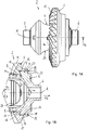
- FIGS 1A to 1C show an inventive connecting assembly 2 in a first embodiment.
- the connecting assembly 2 comprises a first drive element 3 and a second drive element 4 that are firmly connected to each other so that torque can be transmitted between the first and second drive elements 3, 4.
- the first drive element 3 is configured in the form of a ring gear.
- the ring gear has a ring gear toothing 11 that can be made to meshingly engage a corresponding pinion gear so that the ring gear 3 can be rotatingly driven around an axis of rotation A.
- the second drive element 4 is configured in the form of a rotatable housing.
- the housing 4 has a first bearing portion 5 and a second bearing portion 6 that can be rotatingly supported around the axis of rotation relative to a stationary component (not shown).
- the ring gear 3 is machined to a finished state prior to assembly and welding to the housing 4.
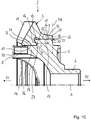
- FIGS 1B and 1C show the connecting assembly 2 between the first drive element 3 and the second drive element 4 in detail.
- the first drive element 3 comprises a sleeve portion 7 and a ring portion 8 that extends radially inwardly from the sleeve portion, such that an inner face 9 of the sleeve portion 7 has a larger diameter than an inner face 10 of the ring portion 8.
- the sleeve portion 7 surrounds an opening 14 for receiving a respective flange portion 15 of the second drive element 4.
- the sleeve portion 7 can also be referred to as receiving portion into which the second drive element 4 is axially inserted.
- the first drive element 3 further comprises a first tapered face 12 that forms an axial end of the ring portion 8 towards the opening 14 enclosed by the sleeve portion 7.
- the tapered face 12 is configured so as to form a radial undercut in the first drive element 3, i.e. a tapered angle ⁇ defined by the conical face 12 opens axially in direction R1 towards the ring portion 8.
- the first drive element has a radial recess 13 that is formed between the cylindrical inner face 9 of the sleeve portion 7 and the tapered face 12.
- the angle ⁇ amounts to about 120°, i.e. the respective half angle ⁇ /2 enclosed between the first tapered face 12 and the axis of rotation A amounts to about 60°. It is understood that other angles may be used, such as angles ⁇ greater than 80 ° and/or smaller than 140°. It can be seen that the second tapered face16 has the same angle ⁇ .
- the outer contour of the second drive element 4 substantially corresponds to the inner contour of the first drive element 3. More specifically, the second drive element 4 comprises a radially outwardly projecting and circumferentially extending flange portion 15 that is formed so as to fit into the receiving portion 7 of the first drive element 3.
- the flange portion 15 comprises the second tapered face 16 that forms an axial end of the flange portion towards the ring portion 8 of the first drive element 3, an outer cylindrical face 17 and a side face 19 forming the other axial end of the flange portion 15.
- the second tapered face 16 is configured so as to form a radial undercut in the second drive element 4, i.e. the tapered angle ⁇ defined by the second tapered face 16 opens axially towards the ring portion 8, too.
- first tapered 12 and the second tapered face 16 contact each other, wherein the first drive element 3 is axially supported against the second drive element 4 in a direction R2 towards the flange portion 15, so that a support region 23 is formed.
- first tapered face 12 and the second tapered face 16 are formed as conical faces, so that the tapered angles can also be referred to as cone angles.
- a first connecting portion 20 of the first drive element 3 is arranged radially vis a vis a second connecting portion 21 of the second drive element 4.
- the first and second connecting portions 20, 21 are welded to each other, wherein a weld connection 22 is formed. It can be seen that the weld connection 22 is axially distanced from the support connection 23 defined by the first and second conical faces 12, 16. More specifically, a root 36 of the weld region 22 and a root 37 of the support connection 23 are arranged with an axial distance L from each other.
- the tolerances of the cylindrical inner face 9 of the sleeve portion 7 of the first drive element 3 and the cylindrical outer face 17 of the flange portion 15 are configured such that a transition fit is formed between said cylindrical inner and outer faces 9, 17.
- a low clearance fit for example up to 45 ⁇ m, or a low press fit, for example up to 45 ⁇ m, may be provided between the cylindrical faces 9, 17 before being welded to each other.
- the same is also applicable for the seat region formed between the ring portion 8 and the housing 4.
- a transition fit can be formed between the inner cylindrical face 10 of the ring portion 8 and the outer cylindrical face 31 of the housing portion 32.
- the weld is produced by an axial welding extending in circumferential direction around the longitudinal axis A between an axial end region of the sleeve portion 7 and an axial end region of the flange portion 15. Said end regions that are configured to be weldingly connected to each other are also be referred to as first and second connecting portions 20, 21.
- the welding connection 22 is axially delimited by the first side face 18 of the first drive element 3 and the second side face 19 of the second drive element 4. It can be seen that the first and second side faces 18, 19 are arranged substantially in one common side face plane P18.
- the step of welding can be effected by rotating the connecting assembly 2 relative to a welding device. Welding the first and second drive elements 3, 4 can be effected by a high-energy beam, such as a laser beam. A filler material for the weld may be used, if necessary.
- the first and second drive element 3, 4 are preferably made from a metal material.
- the first drive element 3 can be made from a case-hardening steel, and the second drive element 4 can be produced from a cast material, for example.
- the first drive element 3 has a conical toothing 11, wherein an opening angle ⁇ of the conical toothing 11 opens in axial direction R2 towards the first and second conical faces 12, 16 of the assembly.
- an axial force resulting from a pinion meshing with the ring gear 3 is introduced from the ring gear 3 into the housing 4 by the conical faces 12, 16.
- the ring portion 8 and the toothing 11 of the drive gear 3 partially axially overlap a central housing plane P4 of the housing 4.
- the central housing plane P4 is arranged perpendicular to the axis of rotation A.
- the housing 4 is formed as a differential carrier having two bores 33 for accommodating a bearing journal (not shown).
- the bearing journal serves to rotatingly support two differential gears around a journal axis B.
- the differential gears are made to engage a first and a second sideshaft gear (not shown) which are arranged coaxially relative to the axis of rotation A in the housing 4.
- the two sideshaft gears serve to drive a respective sideshaft for transmitting torque to the vehicle wheels.
- the housing 4 has two radial openings 24 through which the differential gears and sideshaft gears can be inserted and mounted into the housing 4.
- the housing 4 can be made from one piece, i.e. integrally, for example by casting technique.
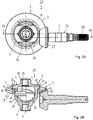
- FIGS 2A and 2B which will be described jointly below show a drive assembly 25 with a connecting assembly 2 similar to the connecting assembly according to Figures 1A to 1C .
- the connecting assembly 2 according to Figures 2A and 2B substantially corresponds to the connecting assembly 2 according to Figures 1A to 1C , so that reference is made to the above description.
- Identical and similar components have the same reference numbers as those used in Figures 1A to 1C .
- the drive assembly 25 is configured to transmit torque in a driveline of a motor vehicle. It comprises a drive shaft 26 with a pinion 27 connected thereto, wherein the drive shaft can be rotationally supported in a stationary housing so as to be rotatable around an axis of rotation C. At an end facing away from the pinion 27, the drive shaft has splines 28 for introducing torque from a further driveline component.
- the pinion 27 meshingly engages the toothing 11 of the ring gear 3 so as to rotationally drive the ring gear 3 and the housing 4 around the axis of rotation A.
- the housing 4 of the drive assembly 2 forms a differential cage for accommodating a differential gear set (not shown).
- a torque introduced from the ring gear 3 into the differential cage 4 is split up by the differential gear set and transmitted to two respective side shafts to drive the vehicle wheels.
- FIG 2B one can see two bearing bushes 29 introduced into the sleeve projections 30 of the differential cage 4.
- the journal 34 for rotatingly supporting the differential gears can be seen, that is held the bores 33 of the differential cage 4.
- the drive assembly 25 according to Figures 2A to 2B can also be referred to as differential drive assembly.
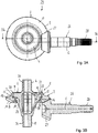
- FIGS 3A and 3B which will be described jointly below show a drive assembly 25 with a connecting assembly 2 according to a further embodiment.
- the connecting assembly 2 according to Figures 3A and 3B widely corresponds to the connecting assembly 2 according to Figures 1A to 1C and Figures 2A to 2B , respectively, so that reference is made to the above description.
- Identical and similar components have the same reference numbers as those used in Figures 1A to 1C and 2A to 2B , respectively.
- the drive assembly 25 is configured in the form of an angle drive assembly, with the housing 4 being formed as a hollow shaft.
- the pinion 27 of the drive shaft 26 engages the toothing 11 of the ring gear 3.
- a torque introduced into the drive shaft 26 is transmitted to the connecting assembly 2, or vice versa.
- the ring gear 3 is connected to the housing 4 via the tapered support connection 23, i.e. cone connection 23, and the welded connection 22.
- the housing 4 is configured in the form of a hollow shaft comprising a housing portion 35 and two sleeve portions 30 axially projecting from the housing portion 35.
- Figures 4 show a connecting assembly 25 in another embodiment.
- the connecting assembly 2 according to Figure 4 substantially corresponds to the connecting assembly 2 according to Figures 1A to 1C , so that reference is made to the above description.
- Identical and similar components have the same reference numbers as those used in Figures 1A to 1C .
- the second drive element 4 is formed as a drive shaft, more particularly a solid drive shaft, wherein it is understood that also a hollow drive shaft may be used.
- the flange portion15 thus has a relatively small diameter.
- the first drive element 3 is formed as a ring gear which has an inner contour corresponding to the outer contour of the drive shaft 4, such that the ring gear 3 can be slid on the drive shaft.
- the tapered face 12 of the ring gear 3 contacts the tapered face 16 of the drive shaft 4 and the outer side face 19 of the flange portion 15 is positioned approximately in the same plane as the side face 18 of the ring gear 3.
- the recess 13 is relatively big and extends from the first connecting portion 20 towards the tapered face 12 of the ring gear 3.
- the inner face 9 of the ring gear 3 opens towards the recess, i.e. is substantially conical.
- the outer face 17 of the flange portion 15 is slightly conical towards the support connection 23.
- An annular gap is formed between the inner face 9 of the ring gear 3 and the outer face 17 of the drive shaft 4.
- the first and second connecting portions 20, 21 are welded to each other so that a welded connection 22 is formed.
- the first and second connecting portions 20, 21 have cylindrical faces towards each other.
- the weld connection 22 is axially distanced from the support connection 23 defined by the first and second conical faces 12, 16 by a length L.
- the opening angle ⁇ of the conical toothing 11 opens in axial direction R2 towards the support connection 23 of the assembly so that axial forces introduced into the ring gear 3 are axially supported by the support face 16 and do not negatively affect the welding connection 22.
- FIGS 5A and 5B that will be jointly described hereinafter show a connecting assembly 25 in another embodiment.
- the connecting assembly 2 according to Figures 5A and 5B substantially corresponds to the connecting assembly 2 according to Figure 4 , so that reference is made to the above description.
- Identical and similar components have the same reference numbers as those used in Figures 4 and 1A to 1C , respectively.
- a difference of the embodiment shown in Figures 5A and 5B is that the tapered face 12 of the ring gear 3 has a curved contour in a longitudinal section.
- the tapered face 16 of the drive shaft is conical, as shown in the other embodiments. Between the curved tapered face 12 and the conical tapered face 16 a contact is formed.
- a tangent T to the tapered faces 12, 16 in the contact region of contact defines a tapered angle ⁇ that opens in an axial direction away from the fixed connection 22.
- the tapered angle ⁇ that can also be referred to as tangent angle, amounts to less than 180° and can be between 80° and 160°, for example. Accordingly, half the tapered angle ( ⁇ /2) is smaller than 90°.
- the annular contact face between the first and second tapered faces 12, 16 is relatively small. Otherwise, the present embodiment corresponds to the above-described embodiments so that reference is hereby made to the above description.
- Figures 6 show a connecting assembly 25 in another embodiment.
- the connecting assembly 2 according to Figure 6 substantially corresponds to the connecting assembly 2 according to Figure 4 , so that reference is made to the above description.
- Identical and similar components have the same reference numbers as those used in Figure 4 .
- the support connection 23 is configured such that the tapered angle ⁇ formed between the first tapered face 12 and the second tapered face 16 opens in an axial direction towards the fixed connection 22.
- the ring gear 3 has an axial recess 38 in a side face thereof, wherein said axial recess forms the support portion with the first tapered face 12 of the ring gear 3.
- the flange portion 15 of the drive shaft 4 comprises an axial extending support portion forming the second tapered face 16.
- the support portion of the drive shaft 4 axially extends into the annular recess 38 of the ring gear 3 so as to form the support connection 23, wherein the first tapered face 12 is in contact with the second tapered face 16.
- the welded fixed connection 22 is arranged on the axial opposite side of the ring gear 3, i.e. at an axial distance L from the support connection 23.
- the inner face 9 of the ring gear 3 and the outer face 17 of the drive shaft 4 are cylindrical faces, but not limited thereto. A transition fit, slight press fit or slight clearance fit can be formed between the inner and outer faces 9, 17.
- the connecting assemblies 2 thus feature a high overall strength so that, as a consequence, the cross section of the first drive element 3 can be downsized to reduce mass. Furthermore, due to the support connection 23 being axially offset from the fixed connection 22, in a half-longitudinal sectional view, a tripodlike structure is formed between the force introduction point of the first drive element 3, the support connection 23 and the fixed connection 22. Thus, forces and bending moments can be supported very well and deformation of the connecting assembly 2 is minimised.
Landscapes
- Engineering & Computer Science (AREA)
- General Engineering & Computer Science (AREA)
- Mechanical Engineering (AREA)
- Retarders (AREA)
- Gears, Cams (AREA)
Description
- The invention relates to a connecting assembly, in particular for transmitting rotary movement, and to a method of producing such a connecting assembly.
- Connecting assemblies can be used for example in the driveline of a motor vehicle. More particularly, they can be part of a mechanical device for transmitting rotary movement in the driveline between an input element and an output element. Such mechanical devices can be for example, drive shafts, gearings, transmissions, couplings or clutches, without being limited thereto.
- From
document DE 10 2009 045 424 A1 a differential gearing is known comprising a differential cage and a ring gear connected thereto. The differential cage comprises a cylindrical outer seat portion and a flange portion extending outwardly therefrom. The ring gear has a cylindrical inner seat portion and an annular web that extends in axial direction. The ring gear and the differential cage are connected to each other with an axial weld that extends in circumferential direction between the flange portion of the differential cage and the annular web of the ring gear. - From
WO 2011 064 206 A1 a connecting assembly is known that is part of a differential gearing for the driveline of a motor vehicle. The connecting assembly comprises a first housing part with a first flange portion and a second housing part with a second flange portion, and a driving gear having a receiving portion for receiving the first and second flange portions. Only the second flange portion is welded to the driving gear, whereas the first flange portion remains non-welded with regard to the connection with the driving gear. The weld is configured as an axial weld between an annular lip of the second housing part and an annular lip of the driving gear - From
EP 2 538 119 A1 - It is an object of the present invention to propose a connecting assembly, more particularly for being used in the driveline of a motor vehicle, that allows to keep deformation of the connected parts low and that has a reduced mass. Furthermore, it is an object to propose a suitable method of producing such a connecting assembly-
- The objective is achieved by the features of
claim 1. - The term tapered in the context of the present invention is meant to include that the tapered faces can be at least partially conical and/or at least partially curved. However, the tapered faces of the first and second drive element are formed such that, in a longitudinal sectional view, an acute angle is enclosed between a tangent to a contact region between the first and second tapered faces and the longitudinal axis. Said acute angle can axially open in direction away from or towards the fixed connection.
- The fixed connection between the first drive element and the second drive element can include any kind of mechanical connection, such as a bolted and/or threaded connection, and/or any kind of bonding connection, such as a welded, soldered or glued connection.
- An advantage is that the tapered faces of the support region are used for radially centering the first and second drive elements relative to each other. Furthermore, deformation of the first and second drive elements under load can be kept low. The tapered faces, in particular an inverted taper, makes the structure of the second drive element contribute on the strength of the first drive element. A lower axial and radial deflection under load is achieved. Furthermore, the overall strength of the connecting assembly is improved because of a better support of the first drive element relative to the second drive element. As a consequence, the cross section of the first drive element can be downsized to reduce mass or to enable the use of a different material, such as powder metal.
- Another advantage is that production and assembly expenditure for producing the connecting assembly can be kept low. Only one single connection must be effected, i.e. the fixed connection, for firmly connecting the two drive elements with each other, whereby also a form-fitting support connection is generated by the tapered faces. Thus, connection of the first and second drive element can be overall carried out quickly and cost-effectively. After the fixed connection is established, the support connection cannot be loosened any more, respectively, only by disconnecting the fixed connection again.
- According to an embodiment, the fixed connection can be at least partially axially offset from the support connection. Due to the support connection and the fixed connection being axially offset from each other, forces and bending moments introduced into the first drive element, for example by a gear toothing or other torque transmitting structure, can be well supported and introduced into the second drive element. In an embodiment wherein the fixed connection is a welded connection, a root of the weld region and a root of the support region can be arranged with an axial offset from each other. For example, an axial distance between the support connection root and the weld root can amount to at least 25 % of the axial length of the first drive element.
- A first half angle is enclosed between the first tapered face and the axis of rotation of the connecting assembly. Said half angle can also be referred to as tangent angle. More specifically, said half angle is smaller than 90°, i.e. the tapered full angle is smaller than 180°. For example, the half angle can be greater than 40° and/or smaller than 70°. The second tapered face preferably has the same angle, i.e. the second half angle enclosed between the second tapered face and the axis of rotation is also smaller than 90°. The first tapered face and/or the second tapered face can be circumferentially closed, i.e. annular faces. However, it is understood that the first and/or the second tapered faces can be parts of circumferentially distributed segments of the respective first and/or second drive element. The first tapered face is axially supported against the second tapered face preferably directly, i.e. the first and second tapered faces contact each other. As an alternative, the first and second tapered faces can also be axially supported against each other indirectly, i.e. via an intermediate component arranged therebetween.
- The support connection can be configured such that the tapered angle opens in an axial direction away from the fixed connection. As an alternative, the support connection can also be configured such that the tapered angle opens in an axial direction towards the fixed connection. However, in both cases a radial undercut is formed between the support portion of the first drive element and the support portion of the second drive element so that a form-locking connection is achieved.
- According to an embodiment, the first drive element can comprise a sleeve portion and the second drive element can comprise a flange portion that is received in the sleeve portion of the first drive element. The first connecting region can be formed by a welding extending in circumferential direction between the sleeve portion and the flange portion. A welded connection can have the advantage that the support connection is axially and radially pretensioned by shrinkage forces during cooling of the welded connection. An axial welding can have the advantage that the use of filler-wire may be reduced or even eliminated. An axial weld is particularly objected to axial and tangential shear stress. However, there is no tension in the root of the weld that is located perpendicular to the weld slot so that the overall endurance of the weld is enhanced. Furthermore, an axial welding has a positive influence on the stress distribution between the first and second drive elements. However, it is understood that the welding can also be configured as radial welding or fillet welding between the first and second drive elements.
- The first drive element comprises a first side face and the second drive element comprises a second side face, wherein the first and second side faces may laterally delimit the welding region, i.e. can be arranged adjacent to the welding region. More particularly, the first and second side faces may be arranged at least substantially in one common side face plane, i.e. the first side face can be flush with the second side face.
- The first drive element can comprise a ring portion through which the second drive element extends in an axial direction. According to one embodiment, an inner face of the ring portion and a respective outer face of the second drive element can be cylindrical faces. In this case, a slight press fit may be formed between the inner face of the ring portion and the outer face of the second drive element. A slight press fit may include values of 5 µm to 45 µm, for example. As an alternative, a clearance fit may also be formed between the cylindrical inner face of the ring portion and the cylindrical outer face of the second drive element. Keeping the radial clearance in the cone region at a minimum contributes to make the production of the assembly robust. Due to the cone design it is even possible that a small clearance fit closes to zero under operation, since the external forces acting on the first drive element make the ring portion to be moved radially inwardly so that the radial clearance is reduced under load. It is also possible, however, that a transition fit is provided between the inner face of the ring portion and the respective outer face of the second drive element. A transition fit in the context of this disclosure is meant to include a zero press fit, a low clearance fit as well as a low press fit. The transition fit may also be referred to as medium fit. A transition fit has the advantage that deformation of the contacting drive elements are kept low, which otherwise occur when using a tight press fit, however thereby still having sufficient radial support to keep an out-of-balance or run-out low. According to another embodiment, however, the inner face of the ring portion and the respective outer face of the second drive element can also deviate from a cylindrical form and can also be conical, for example.
- The fixed connection may be radially offset from the support connection, which includes an embodiment wherein a medium diameter of the fixed connection is greater than a medium diameter of the support connection, and an alternative embodiment wherein a medium diameter of the fixed connection is smaller than a medium diameter of the support connection.
- According to an embodiment, the first drive element can comprise a radial recess between the inner face of the sleeve portion and the first tapered face. The radial recess provides a tool run-out for manufacturing an inner face of the sleeve portion and the first connecting portion, respectively. Furthermore, stress peaks that may occur in the first drive element during or after welding or during operation of the connecting assembly can be kept low as an advantage.
- The first and second drive element can be generally any kind of torque transmitting component in the driveline of a motor vehicle. For example, a drive element can be formed as a geared component, such as a ring gear for introducing torque into a gearing or coupling. A drive element can also be configured as a housing component, such as a gearing cage or coupling cage.
- According to an exemplary embodiment, the first drive element can be configured as a toothed gear, such as a ring gear or crown gear and having a gear toothing. The second drive element can be configured as a rotatable housing that may be rotatingly supported around the axis of rotation in a stationary component. For a compact design of the connecting assembly, a portion of the ring gear toothing may be arranged so as to axially overlap a central housing plane of the housing, with the central housing plane being arranged perpendicular to the axis of rotation, preferably axially between a first and second bearing portion of the rotatable housing.
- The toothed gear may have a conical toothing, wherein an opening angle of the conical toothing opens in axial direction towards the first and second conical faces of the assembly. By this design, axial forces resulting from torque transmission between a pinion gear and the toothed gear are axially supported by the tapered faces, i.e. by the support region that can also be referred to as tapered connection.
- The toothed gear serves for introducing torque into the connecting assembly. Instead of the toothed gear, it is also possible to use a pulley or a chain disc for introducing torque. As mentioned above, the connecting assembly may be part of a gearing, such as a differential gearing that splits a torque introduced by the toothing of the first drive element and transmits same to two output parts. A further application for the connecting assembly can be an angular drive assembly that transmits torque from a first drive shaft to a second drive shaft arranged at an angle thereto. Another embodiment may include that the connecting assembly is part of a coupling which serves to connect, on demand, a secondary driving axle in the driveline of a motor vehicle driven by a plurality of axles.
- The above-mentioned objective is further achieved by providing a method of producing a connecting assembly for transmitting torque, the method comprising the following steps: producing a first drive element having a longitudinal axis, the first driving element comprising a first connecting portion, a receiving portion and a first tapered face; producing a second drive element comprising a second connecting portion and a second tapered face; inserting the second drive element into the first drive element up to a fully inserted position in which the first tapered face and the second tapered face are axially supported against each other and interlock each other with an undercut, thereby coaxially aligning the first drive element and the second drive element relative to each other; and producing a fixed connection between the first connecting portion to the second connecting portion, wherein by producing the fixed connection between the first and second connecting portions, a form-fitting supporting connection is established between the first tapered face of the first drive element and the second tapered face of the second drive element.
- The method substantially has the same advantages as the disclosed connecting assembly so that reference can be made to the above description. It is thus understood that all product-related features can also be adapted to the method and, vice versa, all method-related features can also be adapted to the product. A particular advantage of the product design relating to the method is that only one single fixed connection is necessary to firmly connect the two drive elements to each other, thereby generating two connecting regions. That is, by effecting the fixed connection, a support connection is formed by the tapered faces that interlock each other with an undercut. As mentioned above, the interlocking effect of the tapered faces contributes to only little deformation of the first and second drive element and the overall strength of the connecting assembly is improved. As mentioned above, an angle formed by the first tapered face and the second tapered face, respectively, can open in a direction away from the fixed connection. As an alternative, the support connection can also be configured such that an angle formed by the first tapered face and the second tapered face, respectively, can open in a direction axially towards the fixed connection.
- The first drive element can comprise a first side face adjacent to the first connecting portion and the second drive element can comprise a second side face adjacent to the second connecting portion, wherein, in the fully inserted condition, the first side face and the second side face are at least approximately flush with each other.
- According to an embodiment, the first drive element and the second drive element can be produced such that a transition fit is formed between at feast one inner face of the first drive element and a respective outer face of the second drive element. A transition fit contributes to an easy assembly, since the risk of shearing material during the step of axially pressing the drive elements towards each other is reduced, if not eliminated. The first drive element can be produced such that a radial recess is formed axially adjacent to the first contact portion, thereby forming a tool run-out for the manufacturing process.
- The fixed connection can be effected by welding, with other connecting methods not being excluded. With reference to the axis of rotation of the first and second drive elements, the welding operation can take place in an axial direction between an inner cylindrical face of the receiving portion of the first drive element and an outer cylindrical face of the second drive element. More particularly, welding can be effected by rotating the connecting assembly relative to the welding device and the welding beam. The term "axial direction" in this context is meant to include certain deviations caused by production. The process of welding the first drive element to the second drive element is preferably effected by a high-energy beam, more particularly by a laser beam or an electron beam. Laser beam welding offers the advantage of a high process speed, and due to rapid cooling of the joined zone, shrinkage forces are generated which, in turn, may effect an axial pretension of the cone connection region.
- According to an embodiment, the tapered faces of the first drive element and the second drive element are orientated such that an axial force of the first tapered face towards the second tapered face leads to a radial force component loading the first tapered face radially inwards. Thus, the tapered support region contributes to a firm connection between the first and second drive element. The tapered faces can have any shape having a variable diameter along the length thereof, such as a conical, arced, concave or convex, or mixtures thereof. Furthermore, the shape of the first tapered face can be different from the shape of the second tapered face. For example, one of the tapered faces can be conical and the other one of the tapered faces can be convex. However, in any case, a tangent angle enclosed between the longitudinal axis and a tangent to the tapered contact faces axially opens in direction away from the fixed connection.
- The first and second drive elements can be made from the same or different material. For example, one of the drive elements can be produced from a case-hardening steel. Case-hardening steel is characterised by a high degree of toughness and a high degree of hardness on the surface and thus, overall, comprises a high degree of resistance against wear. Another one of the drive elements can be produced from a cast material.
- Preferred embodiments will be explained below with reference to the drawings. Herein,
- Figure 1A
- shows an inventive connecting assembly according to a first embodiment in a side view;
- Figure 1B
- is a longitudinal section of the connecting assembly shown in
Figure 1A according to section 1b-1b ofFigure 1A ; - Figure 1C
- shows a part of the connecting assembly of
Figure 1B in greater detail; - Figure 2A
- shows a drive assembly with an inventive connecting assembly in a similar embodiment in an axial view;
- Figure 2B
- is a longitudinal section of the drive assembly according to
section 2b-2b ofFigure 2A ; - Figure 3A
- shows a drive assembly with an inventive connecting assembly according to another embodiment in an axial view;
- Figure 3B
- is a longitudinal section of the drive assembly according to section 3b-3b of
Figure 3A ; - Figure 4
- shows an inventive connecting assembly according to another embodiment in a half-longitudinal section;
- Figure 5A
- shows an inventive connecting assembly according to another embodiment in a half-longitudinal section;
- Figure 5B
- the connecting assembly according to
Figure 5A as an enlarged detail; and - Figure 6
- shows an inventive connecting assembly according to another embodiment in a half-longitudinal section.
-
Figures 1A to 1C , which will be described jointly below, show an inventive connectingassembly 2 in a first embodiment. The connectingassembly 2 comprises afirst drive element 3 and asecond drive element 4 that are firmly connected to each other so that torque can be transmitted between the first andsecond drive elements - The
first drive element 3 is configured in the form of a ring gear. The ring gear has aring gear toothing 11 that can be made to meshingly engage a corresponding pinion gear so that thering gear 3 can be rotatingly driven around an axis of rotation A. Thesecond drive element 4 is configured in the form of a rotatable housing. Thehousing 4 has afirst bearing portion 5 and asecond bearing portion 6 that can be rotatingly supported around the axis of rotation relative to a stationary component (not shown). Thering gear 3 is machined to a finished state prior to assembly and welding to thehousing 4. -
Figures 1B and1C show the connectingassembly 2 between thefirst drive element 3 and thesecond drive element 4 in detail. Thefirst drive element 3 comprises asleeve portion 7 and aring portion 8 that extends radially inwardly from the sleeve portion, such that aninner face 9 of thesleeve portion 7 has a larger diameter than aninner face 10 of thering portion 8. Thesleeve portion 7 surrounds anopening 14 for receiving arespective flange portion 15 of thesecond drive element 4. Thus, thesleeve portion 7 can also be referred to as receiving portion into which thesecond drive element 4 is axially inserted. - The
first drive element 3 further comprises a firsttapered face 12 that forms an axial end of thering portion 8 towards the opening 14 enclosed by thesleeve portion 7. The taperedface 12 is configured so as to form a radial undercut in thefirst drive element 3, i.e. a tapered angle α defined by theconical face 12 opens axially in direction R1 towards thering portion 8. The first drive element has aradial recess 13 that is formed between the cylindricalinner face 9 of thesleeve portion 7 and the taperedface 12. The angle α amounts to about 120°, i.e. the respective half angle α/2 enclosed between the firsttapered face 12 and the axis of rotation A amounts to about 60°. It is understood that other angles may be used, such as angles α greater than 80 ° and/or smaller than 140°. It can be seen that the second tapered face16 has the same angle α. - The outer contour of the
second drive element 4 substantially corresponds to the inner contour of thefirst drive element 3. More specifically, thesecond drive element 4 comprises a radially outwardly projecting and circumferentially extendingflange portion 15 that is formed so as to fit into the receivingportion 7 of thefirst drive element 3. Theflange portion 15 comprises the secondtapered face 16 that forms an axial end of the flange portion towards thering portion 8 of thefirst drive element 3, an outercylindrical face 17 and aside face 19 forming the other axial end of theflange portion 15. The secondtapered face 16 is configured so as to form a radial undercut in thesecond drive element 4, i.e. the tapered angle α defined by the secondtapered face 16 opens axially towards thering portion 8, too. The first tapered 12 and the secondtapered face 16 contact each other, wherein thefirst drive element 3 is axially supported against thesecond drive element 4 in a direction R2 towards theflange portion 15, so that asupport region 23 is formed. In the present embodiment, the firsttapered face 12 and the secondtapered face 16 are formed as conical faces, so that the tapered angles can also be referred to as cone angles. - In a fully inserted condition, i.e. when the two tapered faces 12, 16 contact each other, the outer side face 19 of the
flange portion 15 is positioned approximately in the same plane P18 as theside face 18 of thefirst drive element 3, which laterally delimits the receivingportion 7. Furthermore, a first connectingportion 20 of thefirst drive element 3 is arranged radially vis a vis a second connectingportion 21 of thesecond drive element 4. The first and second connectingportions weld connection 22 is formed. It can be seen that theweld connection 22 is axially distanced from thesupport connection 23 defined by the first and second conical faces 12, 16. More specifically, aroot 36 of theweld region 22 and aroot 37 of thesupport connection 23 are arranged with an axial distance L from each other. - The tolerances of the cylindrical
inner face 9 of thesleeve portion 7 of thefirst drive element 3 and the cylindricalouter face 17 of theflange portion 15 are configured such that a transition fit is formed between said cylindrical inner andouter faces ring portion 8 and thehousing 4. There, a transition fit can be formed between the innercylindrical face 10 of thering portion 8 and the outercylindrical face 31 of thehousing portion 32. Thus, deformation is kept low when thefirst drive element 3 is axially pushed or moved onto thesecond drive element 4. After axially inserting thesecond drive element 4 into thefirst drive element 3, i.e. up to a condition in which the first and second conical faces 12, 16 contact each other, welding is effected in the region between the first and second connectingportion connection 22 is formed. - The weld is produced by an axial welding extending in circumferential direction around the longitudinal axis A between an axial end region of the
sleeve portion 7 and an axial end region of theflange portion 15. Said end regions that are configured to be weldingly connected to each other are also be referred to as first and second connectingportions welding connection 22 is axially delimited by thefirst side face 18 of thefirst drive element 3 and thesecond side face 19 of thesecond drive element 4. It can be seen that the first and second side faces 18, 19 are arranged substantially in one common side face plane P18. The step of welding can be effected by rotating the connectingassembly 2 relative to a welding device. Welding the first andsecond drive elements - The first and
second drive element first drive element 3 can be made from a case-hardening steel, and thesecond drive element 4 can be produced from a cast material, for example. - It can be seen that the
first drive element 3 has aconical toothing 11, wherein an opening angle β of theconical toothing 11 opens in axial direction R2 towards the first and second conical faces 12, 16 of the assembly. By this design, an axial force resulting from a pinion meshing with thering gear 3 is introduced from thering gear 3 into thehousing 4 by the conical faces 12, 16. Thering portion 8 and thetoothing 11 of thedrive gear 3 partially axially overlap a central housing plane P4 of thehousing 4. The central housing plane P4 is arranged perpendicular to the axis of rotation A. - In the embodiment according to
Figures 1A to 1C , thehousing 4 is formed as a differential carrier having twobores 33 for accommodating a bearing journal (not shown). The bearing journal serves to rotatingly support two differential gears around a journal axis B. The differential gears are made to engage a first and a second sideshaft gear (not shown) which are arranged coaxially relative to the axis of rotation A in thehousing 4. The two sideshaft gears serve to drive a respective sideshaft for transmitting torque to the vehicle wheels. It can be seen inFigure 1A that thehousing 4 has tworadial openings 24 through which the differential gears and sideshaft gears can be inserted and mounted into thehousing 4. Thehousing 4 can be made from one piece, i.e. integrally, for example by casting technique. -
Figures 2A and 2B which will be described jointly below show adrive assembly 25 with a connectingassembly 2 similar to the connecting assembly according toFigures 1A to 1C . The connectingassembly 2 according toFigures 2A and 2B substantially corresponds to the connectingassembly 2 according toFigures 1A to 1C , so that reference is made to the above description. Identical and similar components have the same reference numbers as those used inFigures 1A to 1C . - The
drive assembly 25 is configured to transmit torque in a driveline of a motor vehicle. It comprises adrive shaft 26 with apinion 27 connected thereto, wherein the drive shaft can be rotationally supported in a stationary housing so as to be rotatable around an axis of rotation C. At an end facing away from thepinion 27, the drive shaft hassplines 28 for introducing torque from a further driveline component. Thepinion 27 meshingly engages thetoothing 11 of thering gear 3 so as to rotationally drive thering gear 3 and thehousing 4 around the axis of rotation A. - The
housing 4 of thedrive assembly 2 forms a differential cage for accommodating a differential gear set (not shown). A torque introduced from thering gear 3 into thedifferential cage 4 is split up by the differential gear set and transmitted to two respective side shafts to drive the vehicle wheels. InFigure 2B , one can see two bearingbushes 29 introduced into thesleeve projections 30 of thedifferential cage 4. Furthermore, thejournal 34 for rotatingly supporting the differential gears can be seen, that is held thebores 33 of thedifferential cage 4. Thedrive assembly 25 according toFigures 2A to 2B can also be referred to as differential drive assembly. -
Figures 3A and 3B which will be described jointly below show adrive assembly 25 with a connectingassembly 2 according to a further embodiment. The connectingassembly 2 according toFigures 3A and 3B widely corresponds to the connectingassembly 2 according toFigures 1A to 1C andFigures 2A to 2B , respectively, so that reference is made to the above description. Identical and similar components have the same reference numbers as those used inFigures 1A to 1C and2A to 2B , respectively. - The
drive assembly 25 according toFigures 3A and 3B is configured in the form of an angle drive assembly, with thehousing 4 being formed as a hollow shaft. Thepinion 27 of thedrive shaft 26 engages thetoothing 11 of thering gear 3. A torque introduced into thedrive shaft 26 is transmitted to the connectingassembly 2, or vice versa. As in the above embodiments, thering gear 3 is connected to thehousing 4 via the taperedsupport connection 23, i.e.cone connection 23, and the weldedconnection 22. Thehousing 4 is configured in the form of a hollow shaft comprising a housing portion 35 and twosleeve portions 30 axially projecting from the housing portion 35. -
Figures 4 show a connectingassembly 25 in another embodiment. The connectingassembly 2 according toFigure 4 substantially corresponds to the connectingassembly 2 according toFigures 1A to 1C , so that reference is made to the above description. Identical and similar components have the same reference numbers as those used inFigures 1A to 1C . - A difference of the embodiment shown in
Figure 4 is that thesecond drive element 4 is formed as a drive shaft, more particularly a solid drive shaft, wherein it is understood that also a hollow drive shaft may be used. The flange portion15 thus has a relatively small diameter. Thefirst drive element 3 is formed as a ring gear which has an inner contour corresponding to the outer contour of thedrive shaft 4, such that thering gear 3 can be slid on the drive shaft. - In a slid on condition, the tapered
face 12 of thering gear 3 contacts the taperedface 16 of thedrive shaft 4 and the outer side face 19 of theflange portion 15 is positioned approximately in the same plane as theside face 18 of thering gear 3. Therecess 13 is relatively big and extends from the first connectingportion 20 towards the taperedface 12 of thering gear 3. Theinner face 9 of thering gear 3 opens towards the recess, i.e. is substantially conical. Theouter face 17 of theflange portion 15 is slightly conical towards thesupport connection 23. An annular gap is formed between theinner face 9 of thering gear 3 and theouter face 17 of thedrive shaft 4. As in the above-described embodiments, the first and second connectingportions connection 22 is formed. The first and second connectingportions weld connection 22 is axially distanced from thesupport connection 23 defined by the first and second conical faces 12, 16 by a length L. The opening angle β of theconical toothing 11 opens in axial direction R2 towards thesupport connection 23 of the assembly so that axial forces introduced into thering gear 3 are axially supported by thesupport face 16 and do not negatively affect thewelding connection 22. -
Figures 5A and 5B that will be jointly described hereinafter show a connectingassembly 25 in another embodiment. The connectingassembly 2 according toFigures 5A and 5B substantially corresponds to the connectingassembly 2 according toFigure 4 , so that reference is made to the above description. Identical and similar components have the same reference numbers as those used inFigures 4 and1A to 1C , respectively. - A difference of the embodiment shown in
Figures 5A and 5B is that the taperedface 12 of thering gear 3 has a curved contour in a longitudinal section. The taperedface 16 of the drive shaft is conical, as shown in the other embodiments. Between the curvedtapered face 12 and the conical tapered face 16 a contact is formed. A tangent T to the tapered faces 12, 16 in the contact region of contact defines a tapered angle α that opens in an axial direction away from the fixedconnection 22. The tapered angle α, that can also be referred to as tangent angle, amounts to less than 180° and can be between 80° and 160°, for example. Accordingly, half the tapered angle (α/2) is smaller than 90°. In the present embodiment the annular contact face between the first and second tapered faces 12, 16 is relatively small. Otherwise, the present embodiment corresponds to the above-described embodiments so that reference is hereby made to the above description. -
Figures 6 show a connectingassembly 25 in another embodiment. The connectingassembly 2 according toFigure 6 substantially corresponds to the connectingassembly 2 according toFigure 4 , so that reference is made to the above description. Identical and similar components have the same reference numbers as those used inFigure 4 . - A difference of the embodiment shown in
Figure 4 is that thesupport connection 23 is configured such that the tapered angle α formed between the firsttapered face 12 and the secondtapered face 16 opens in an axial direction towards the fixedconnection 22. Thering gear 3 has anaxial recess 38 in a side face thereof, wherein said axial recess forms the support portion with the firsttapered face 12 of thering gear 3. Accordingly, theflange portion 15 of thedrive shaft 4 comprises an axial extending support portion forming the secondtapered face 16. The support portion of thedrive shaft 4 axially extends into theannular recess 38 of thering gear 3 so as to form thesupport connection 23, wherein the firsttapered face 12 is in contact with the secondtapered face 16. The welded fixedconnection 22 is arranged on the axial opposite side of thering gear 3, i.e. at an axial distance L from thesupport connection 23. Theinner face 9 of thering gear 3 and theouter face 17 of thedrive shaft 4 are cylindrical faces, but not limited thereto. A transition fit, slight press fit or slight clearance fit can be formed between the inner andouter faces - An advantage of all of the above described embodiments is that the tapered faces 12, 16 of have an interlocking effect so that the
first drive element 3 is restricted from being deformed radially outwardly. The connectingassemblies 2 thus feature a high overall strength so that, as a consequence, the cross section of thefirst drive element 3 can be downsized to reduce mass. Furthermore, due to thesupport connection 23 being axially offset from the fixedconnection 22, in a half-longitudinal sectional view, a tripodlike structure is formed between the force introduction point of thefirst drive element 3, thesupport connection 23 and the fixedconnection 22. Thus, forces and bending moments can be supported very well and deformation of the connectingassembly 2 is minimised. -
- 2
- connecting assembly
- 3
- first drive element
- 4
- second drive element
- 5
- first bearing portion
- 6
- second bearing portion
- 7
- sleeve portion
- 8
- ring portion
- 9
- cylindrical inner face
- 10
- inner face
- 11
- toothing
- 12
- first tapered face
- 13
- radial recess
- 14
- opening
- 15
- flange portion
- 16
- second tapered face
- 17
- outer face
- 18
- side face
- 19
- side face
- 20
- connecting portion
- 21
- connecting portion
- 22
- fixed connection
- 23
- support connection
- 24
- opening
- 25
- drive assembly
- 26
- drive shaft
- 27
- pinion
- 28
- splines
- 29
- bearing bush
- 30
- sleeve projection
- 31
- outer face
- 32
- housing portion
- 33
- bore
- 34
- journal
- 35
- housing portion
- 36
- weld root
- 37
- cone root
- 38
- recess
- α
- tapered angle
- β
- opening angle
- A
- axis
- B
- axis
- C
- axis
- L
- distance
- P
- plane
- R
- direction
Claims (16)
- A connecting assembly for transmitting torque in a driveline, comprising:a first drive element (3) having a first connecting portion (20) and a first tapered face (12);a second drive element (4) having second connecting portion (21) and a second tapered face (16);wherein the first connecting portion (20) and the second connecting portion (21) are connected to each other by a fixed connection (22);wherein the first tapered face (12) and the second tapered face (16) are axially supported against each other and interlock each other with an undercut thereby forming a form-fitting support connection (23), wherein the first drive element (3) and the second drive element (4) are radially centered relative to each other by the first tapered face (12) and the second tapered face (16).
- A connecting assembly according to claim 1, characterized in that the fixed connection (22) is at least partially axially offset from the support connection (23).
- A connecting assembly according to claim 1 or 2, characterized in that a half angle (α/2) is enclosed between the first tapered face (12) and an axis of rotation (A) of the connecting assembly, wherein the half angle (α/2) is smaller than 90°.
- A connecting assembly according to any one of claims 1 to 3, characterized in that the first drive element (3) comprises a sleeve portion (7) and the second drive element (4) comprises a flange portion (15) that is received in the sleeve portion (7) of the first drive element (3),
wherein the fixed connection (22) is formed by a welding extending in circumferential direction between the sleeve portion (7) and the flange portion (15). - A connecting assembly according to any one of claims 1 to 4, characterized in that, in a region of the fixed connection (22), the first drive element (3) comprises a first side face (18) and the second drive element (4) comprises a second side face (19), wherein the first side face (18) and the second side face (19) are arranged in one side face plane (P18).
- A connecting assembly according to any one of claims 1 to 5, characterized in that the first drive element (3) comprises a ring portion (8) through which the second drive element (4) extends axially,
wherein a press fit is formed between an inner face (10) of the ring portion (8) and an outer face (31) of the second drive element (4). - A connecting assembly according to any one of claims 4 to 6, characterized in that the first drive element (3) comprises a radial recess (13) between the inner face (9) of the sleeve portion (7) and the first tapered face (12).
- A connecting assembly according to any one of claims 1 to 7, characterized in that the first drive element (3) is configured as a ring gear having a ring gear toothing (11),
wherein the ring gear toothing (11) is conical, wherein an opening angle (β) of the ring gear toothing (11) opens in axial direction (R2) towards the second tapered face (16) of the second drive element (4). - A connecting assembly according to any one of claims 3 to 8, characterized in that the second drive element (4) is configured as at least one of a housing and a drive shaft that is rotatingly supported around the axis of rotation (A).
- A connecting assembly according to any one of claims 1 to 9, characterized in that a root (36) of the fixed connection (22) and a root (37) of the support connection (23) are arranged with an axial offset (L) from each other.
- A connecting assembly according to any one of claims 1 to 10, characterized in that a full angle (α) of the support connection (23) opens in an axial direction (R1) away from the fixed connection (22).
- A method of producing a connecting assembly for transmitting torque, the method comprising the following steps:producing a first drive element (3) having a longitudinal axis (A), the first driving element (3) comprising a first connecting portion (20), a receiving portion (7) and a first tapered face (12);producing a second drive element (4) comprising a second connecting portion (21) and a second tapered face (16);inserting the second drive element (4) into the first drive element (3) up to a fully inserted position in which the first tapered face (12) and the second tapered face (16) are axially supported against each other and interlock each other with an undercut, thereby coaxially aligning the first drive element (3) and the second drive element (4) relative to each other;producing a fixed connection (22) between the first connecting portion (20) and the second connecting portion (21), wherein, by producing the fixed connection (22), a form-fitting support connection (23) is established between the first tapered face (12) of the first drive element (3) and the second tapered face of the second drive element (4).
- A method according to claim 12, characterized in that the first drive element (3) comprises a first side face (18) adjacent to the first connecting portion (20), and the second drive element (4) comprises a second side face (19) adjacent to the second connecting portion (21),
wherein, in the fully inserted condition, the first side face (18) and the second side face (19) are at least approximately flush with each other and the first connecting portion (20) axially overlaps the second connecting portion (21). - A method according to claim 12 to 13, characterized in that the first drive element (3) and the second drive element (4) are produced such that a press fit is formed between an inner face (9, 10) of the first drive element (3) and a respective outer face (17, 31) of the second drive element (4).
- A method according to any one of claims 12 to 14, characterized in that the first drive element (3) is produced such that a radial recess (13) is formed between the inner face (9) of the sleeve portion (7) and the first tapered face (12).
- A method according to any one of claims 12 to 15, characterized in that the fixed connection (22) between the first drive element (3) and the second drive element (4) is effected by welding, more particularly by a high-energy beam.
Applications Claiming Priority (1)
| Application Number | Priority Date | Filing Date | Title |
|---|---|---|---|
| PCT/EP2015/071923 WO2017050375A1 (en) | 2015-09-23 | 2015-09-23 | Connecting assembly and method for producing a connecting assembly |
Publications (2)
| Publication Number | Publication Date |
|---|---|
| EP3353448A1 EP3353448A1 (en) | 2018-08-01 |
| EP3353448B1 true EP3353448B1 (en) | 2020-08-12 |
Family
ID=54199211
Family Applications (1)
| Application Number | Title | Priority Date | Filing Date |
|---|---|---|---|
| EP15770860.3A Active EP3353448B1 (en) | 2015-09-23 | 2015-09-23 | Connecting assembly and method for producing a connecting assembly |
Country Status (3)
| Country | Link |
|---|---|
| EP (1) | EP3353448B1 (en) |
| CN (1) | CN108351012B (en) |
| WO (1) | WO2017050375A1 (en) |
Cited By (1)
| Publication number | Priority date | Publication date | Assignee | Title |
|---|---|---|---|---|
| DE102022112895A1 (en) | 2022-05-23 | 2023-11-23 | Dr. Ing. H.C. F. Porsche Aktiengesellschaft | Connection arrangement for transmitting torque |
Families Citing this family (4)
| Publication number | Priority date | Publication date | Assignee | Title |
|---|---|---|---|---|
| DE102018220105B4 (en) | 2018-11-22 | 2021-01-21 | Audi Ag | Differential gear for a motor vehicle with an output gear pressed onto the housing through two press fits |
| JP7353827B2 (en) * | 2019-06-28 | 2023-10-02 | 武蔵精密工業株式会社 | transmission device |
| JP7405523B2 (en) | 2019-06-28 | 2023-12-26 | 武蔵精密工業株式会社 | transmission device |
| CN113236733B (en) * | 2021-05-25 | 2022-05-20 | 一汽解放汽车有限公司 | Differential mechanism structure and car |
Family Cites Families (8)
| Publication number | Priority date | Publication date | Assignee | Title |
|---|---|---|---|---|
| JPS5135976B1 (en) * | 1971-07-20 | 1976-10-06 | ||
| JPH11294559A (en) * | 1998-04-10 | 1999-10-29 | Tochigi Fuji Ind Co Ltd | Differential limiting device |
| WO2007085847A1 (en) * | 2006-01-27 | 2007-08-02 | Meritor Heavy Vehicle Systems Cameri Spa | Differential gear casing and components thereof |
| DE102009045424A1 (en) | 2009-10-07 | 2011-04-14 | Zf Friedrichshafen Ag | Axle differential for motor vehicle, has crown gear provided in axial flange sided manner with ring-shaped axial web placed opposite to outer circumference of stop flange |
| DE102009056087B4 (en) | 2009-11-30 | 2012-07-26 | Gkn Driveline International Gmbh | Connecting arrangement and method for producing a connection arrangement |
| US8628444B2 (en) * | 2010-07-01 | 2014-01-14 | Metal Forming & Coining Corporation | Flow-formed differential case assembly |
| CA2780125C (en) * | 2011-06-22 | 2016-10-04 | Metal Forming & Coining Corporation | Flow-formed differential case assembly |
| CN204403315U (en) * | 2015-01-27 | 2015-06-17 | 温岭市华鑫机械制造有限公司 | End tooth lockable mechanism in electronics |
-
2015
- 2015-09-23 EP EP15770860.3A patent/EP3353448B1/en active Active
- 2015-09-23 CN CN201580083346.5A patent/CN108351012B/en active Active
- 2015-09-23 WO PCT/EP2015/071923 patent/WO2017050375A1/en active Search and Examination
Non-Patent Citations (1)
| Title |
|---|
| None * |
Cited By (1)
| Publication number | Priority date | Publication date | Assignee | Title |
|---|---|---|---|---|
| DE102022112895A1 (en) | 2022-05-23 | 2023-11-23 | Dr. Ing. H.C. F. Porsche Aktiengesellschaft | Connection arrangement for transmitting torque |
Also Published As
| Publication number | Publication date |
|---|---|
| CN108351012B (en) | 2021-04-20 |
| EP3353448A1 (en) | 2018-08-01 |
| CN108351012A (en) | 2018-07-31 |
| WO2017050375A1 (en) | 2017-03-30 |
Similar Documents
| Publication | Publication Date | Title |
|---|---|---|
| EP3353448B1 (en) | Connecting assembly and method for producing a connecting assembly | |
| EP2507533B1 (en) | Connecting assembly and method of producing a connecting assembly | |
| US7695392B2 (en) | Differential mechanism assembly | |
| US8544174B2 (en) | Differential mechanism having multiple case portions | |
| US8221278B2 (en) | Spur gear differential | |
| US4893960A (en) | Wheel Bearing/constant velocity joint unit | |
| JP4094879B2 (en) | Axle shaft manufacturing method | |
| US6227716B1 (en) | Differential unit having an adjustable bearing assembly | |
| US20100113206A1 (en) | Eccentric oscillating type speed reducer and apparatus for rotating stabilizer shaft using the eccentric oscillating type speed reducer | |
| CA2614092C (en) | Prestressed shaft/hub connection having a perfect cone shape | |
| EP1179440B1 (en) | Bearing device for drive wheel of a vehicle | |
| US20100075795A1 (en) | Crown gear and differential assembly with a crown gear | |
| CN114729688A (en) | Drive device for vehicle | |
| US20170227110A1 (en) | Method For Fixing A Bushing In A Through Bore Of A Gear Of The Idler Gear Assembly | |
| US20030108384A1 (en) | Polygonal interface between driving and driven components | |
| US20100284736A1 (en) | Coupling element for transmitting torque and drive unit comprising said coupling element | |
| US6324930B1 (en) | Gear assembly | |
| CN108603580B (en) | Differential assembly with two-piece carrier and welded ring gear | |
| US20130147257A1 (en) | Wheel bearing assembly comprising a joint and corresponding method of manufacture | |
| US8245598B2 (en) | Differential carrier consisting of half-shells and a process of producing a differential carrier | |
| DE10238236B4 (en) | Transverse differential of a motor vehicle and manufacturing method for such | |
| CA2427980A1 (en) | Rotating housing and gear assembly | |
| US4343563A (en) | Tapered spline and method of manufacturing same | |
| US20080268991A1 (en) | Method for producing a conical pulley, a conical pulley, and a belt-driven conical-pulley transmission | |
| US5909789A (en) | Hub body for clutches, especially friction clutches in motor vehicles |
Legal Events
| Date | Code | Title | Description |
|---|---|---|---|
| STAA | Information on the status of an ep patent application or granted ep patent |
Free format text: STATUS: THE INTERNATIONAL PUBLICATION HAS BEEN MADE |
|
| PUAI | Public reference made under article 153(3) epc to a published international application that has entered the european phase |
Free format text: ORIGINAL CODE: 0009012 |
|
| STAA | Information on the status of an ep patent application or granted ep patent |
Free format text: STATUS: REQUEST FOR EXAMINATION WAS MADE |
|
| 17P | Request for examination filed |
Effective date: 20180126 |
|
| AK | Designated contracting states |
Kind code of ref document: A1 Designated state(s): AL AT BE BG CH CY CZ DE DK EE ES FI FR GB GR HR HU IE IS IT LI LT LU LV MC MK MT NL NO PL PT RO RS SE SI SK SM TR |
|
| AX | Request for extension of the european patent |
Extension state: BA ME |
|
| DAV | Request for validation of the european patent (deleted) | ||
| DAX | Request for extension of the european patent (deleted) | ||
| GRAP | Despatch of communication of intention to grant a patent |
Free format text: ORIGINAL CODE: EPIDOSNIGR1 |
|
| STAA | Information on the status of an ep patent application or granted ep patent |
Free format text: STATUS: GRANT OF PATENT IS INTENDED |
|
| INTG | Intention to grant announced |
Effective date: 20200305 |
|
| GRAS | Grant fee paid |
Free format text: ORIGINAL CODE: EPIDOSNIGR3 |
|
| GRAA | (expected) grant |
Free format text: ORIGINAL CODE: 0009210 |
|
| STAA | Information on the status of an ep patent application or granted ep patent |
Free format text: STATUS: THE PATENT HAS BEEN GRANTED |
|
| AK | Designated contracting states |
Kind code of ref document: B1 Designated state(s): AL AT BE BG CH CY CZ DE DK EE ES FI FR GB GR HR HU IE IS IT LI LT LU LV MC MK MT NL NO PL PT RO RS SE SI SK SM TR |
|
| REG | Reference to a national code |
Ref country code: CH Ref legal event code: EP |
|
| REG | Reference to a national code |
Ref country code: IE Ref legal event code: FG4D |
|
| REG | Reference to a national code |
Ref country code: DE Ref legal event code: R096 Ref document number: 602015057377 Country of ref document: DE |
|
| REG | Reference to a national code |
Ref country code: AT Ref legal event code: REF Ref document number: 1301854 Country of ref document: AT Kind code of ref document: T Effective date: 20200915 |
|
| REG | Reference to a national code |
Ref country code: LT Ref legal event code: MG4D |
|
| REG | Reference to a national code |
Ref country code: NL Ref legal event code: MP Effective date: 20200812 |
|
| PG25 | Lapsed in a contracting state [announced via postgrant information from national office to epo] |
Ref country code: HR Free format text: LAPSE BECAUSE OF FAILURE TO SUBMIT A TRANSLATION OF THE DESCRIPTION OR TO PAY THE FEE WITHIN THE PRESCRIBED TIME-LIMIT Effective date: 20200812 Ref country code: BG Free format text: LAPSE BECAUSE OF FAILURE TO SUBMIT A TRANSLATION OF THE DESCRIPTION OR TO PAY THE FEE WITHIN THE PRESCRIBED TIME-LIMIT Effective date: 20201112 Ref country code: LT Free format text: LAPSE BECAUSE OF FAILURE TO SUBMIT A TRANSLATION OF THE DESCRIPTION OR TO PAY THE FEE WITHIN THE PRESCRIBED TIME-LIMIT Effective date: 20200812 Ref country code: GR Free format text: LAPSE BECAUSE OF FAILURE TO SUBMIT A TRANSLATION OF THE DESCRIPTION OR TO PAY THE FEE WITHIN THE PRESCRIBED TIME-LIMIT Effective date: 20201113 Ref country code: NO Free format text: LAPSE BECAUSE OF FAILURE TO SUBMIT A TRANSLATION OF THE DESCRIPTION OR TO PAY THE FEE WITHIN THE PRESCRIBED TIME-LIMIT Effective date: 20201112 Ref country code: SE Free format text: LAPSE BECAUSE OF FAILURE TO SUBMIT A TRANSLATION OF THE DESCRIPTION OR TO PAY THE FEE WITHIN THE PRESCRIBED TIME-LIMIT Effective date: 20200812 Ref country code: FI Free format text: LAPSE BECAUSE OF FAILURE TO SUBMIT A TRANSLATION OF THE DESCRIPTION OR TO PAY THE FEE WITHIN THE PRESCRIBED TIME-LIMIT Effective date: 20200812 |
|
| REG | Reference to a national code |
Ref country code: AT Ref legal event code: MK05 Ref document number: 1301854 Country of ref document: AT Kind code of ref document: T Effective date: 20200812 |
|
| PG25 | Lapsed in a contracting state [announced via postgrant information from national office to epo] |
Ref country code: RS Free format text: LAPSE BECAUSE OF FAILURE TO SUBMIT A TRANSLATION OF THE DESCRIPTION OR TO PAY THE FEE WITHIN THE PRESCRIBED TIME-LIMIT Effective date: 20200812 Ref country code: LV Free format text: LAPSE BECAUSE OF FAILURE TO SUBMIT A TRANSLATION OF THE DESCRIPTION OR TO PAY THE FEE WITHIN THE PRESCRIBED TIME-LIMIT Effective date: 20200812 Ref country code: NL Free format text: LAPSE BECAUSE OF FAILURE TO SUBMIT A TRANSLATION OF THE DESCRIPTION OR TO PAY THE FEE WITHIN THE PRESCRIBED TIME-LIMIT Effective date: 20200812 Ref country code: PL Free format text: LAPSE BECAUSE OF FAILURE TO SUBMIT A TRANSLATION OF THE DESCRIPTION OR TO PAY THE FEE WITHIN THE PRESCRIBED TIME-LIMIT Effective date: 20200812 Ref country code: IS Free format text: LAPSE BECAUSE OF FAILURE TO SUBMIT A TRANSLATION OF THE DESCRIPTION OR TO PAY THE FEE WITHIN THE PRESCRIBED TIME-LIMIT Effective date: 20201212 |
|
| PG25 | Lapsed in a contracting state [announced via postgrant information from national office to epo] |
Ref country code: EE Free format text: LAPSE BECAUSE OF FAILURE TO SUBMIT A TRANSLATION OF THE DESCRIPTION OR TO PAY THE FEE WITHIN THE PRESCRIBED TIME-LIMIT Effective date: 20200812 Ref country code: SM Free format text: LAPSE BECAUSE OF FAILURE TO SUBMIT A TRANSLATION OF THE DESCRIPTION OR TO PAY THE FEE WITHIN THE PRESCRIBED TIME-LIMIT Effective date: 20200812 Ref country code: RO Free format text: LAPSE BECAUSE OF FAILURE TO SUBMIT A TRANSLATION OF THE DESCRIPTION OR TO PAY THE FEE WITHIN THE PRESCRIBED TIME-LIMIT Effective date: 20200812 Ref country code: DK Free format text: LAPSE BECAUSE OF FAILURE TO SUBMIT A TRANSLATION OF THE DESCRIPTION OR TO PAY THE FEE WITHIN THE PRESCRIBED TIME-LIMIT Effective date: 20200812 Ref country code: CZ Free format text: LAPSE BECAUSE OF FAILURE TO SUBMIT A TRANSLATION OF THE DESCRIPTION OR TO PAY THE FEE WITHIN THE PRESCRIBED TIME-LIMIT Effective date: 20200812 |
|
| REG | Reference to a national code |
Ref country code: CH Ref legal event code: PL |
|
| REG | Reference to a national code |
Ref country code: DE Ref legal event code: R097 Ref document number: 602015057377 Country of ref document: DE |
|
| PG25 | Lapsed in a contracting state [announced via postgrant information from national office to epo] |
Ref country code: ES Free format text: LAPSE BECAUSE OF FAILURE TO SUBMIT A TRANSLATION OF THE DESCRIPTION OR TO PAY THE FEE WITHIN THE PRESCRIBED TIME-LIMIT Effective date: 20200812 Ref country code: AL Free format text: LAPSE BECAUSE OF FAILURE TO SUBMIT A TRANSLATION OF THE DESCRIPTION OR TO PAY THE FEE WITHIN THE PRESCRIBED TIME-LIMIT Effective date: 20200812 Ref country code: AT Free format text: LAPSE BECAUSE OF FAILURE TO SUBMIT A TRANSLATION OF THE DESCRIPTION OR TO PAY THE FEE WITHIN THE PRESCRIBED TIME-LIMIT Effective date: 20200812 Ref country code: MC Free format text: LAPSE BECAUSE OF FAILURE TO SUBMIT A TRANSLATION OF THE DESCRIPTION OR TO PAY THE FEE WITHIN THE PRESCRIBED TIME-LIMIT Effective date: 20200812 |
|
| PLBE | No opposition filed within time limit |
Free format text: ORIGINAL CODE: 0009261 |
|
| REG | Reference to a national code |
Ref country code: BE Ref legal event code: MM Effective date: 20200930 |
|
| STAA | Information on the status of an ep patent application or granted ep patent |
Free format text: STATUS: NO OPPOSITION FILED WITHIN TIME LIMIT |
|
| PG25 | Lapsed in a contracting state [announced via postgrant information from national office to epo] |
Ref country code: LU Free format text: LAPSE BECAUSE OF NON-PAYMENT OF DUE FEES Effective date: 20200923 Ref country code: SK Free format text: LAPSE BECAUSE OF FAILURE TO SUBMIT A TRANSLATION OF THE DESCRIPTION OR TO PAY THE FEE WITHIN THE PRESCRIBED TIME-LIMIT Effective date: 20200812 |
|
| 26N | No opposition filed |
Effective date: 20210514 |
|
| PG25 | Lapsed in a contracting state [announced via postgrant information from national office to epo] |
Ref country code: FR Free format text: LAPSE BECAUSE OF NON-PAYMENT OF DUE FEES Effective date: 20201012 Ref country code: IT Free format text: LAPSE BECAUSE OF FAILURE TO SUBMIT A TRANSLATION OF THE DESCRIPTION OR TO PAY THE FEE WITHIN THE PRESCRIBED TIME-LIMIT Effective date: 20200812 |
|
| PG25 | Lapsed in a contracting state [announced via postgrant information from national office to epo] |
Ref country code: CH Free format text: LAPSE BECAUSE OF NON-PAYMENT OF DUE FEES Effective date: 20200930 Ref country code: BE Free format text: LAPSE BECAUSE OF NON-PAYMENT OF DUE FEES Effective date: 20200930 Ref country code: SI Free format text: LAPSE BECAUSE OF FAILURE TO SUBMIT A TRANSLATION OF THE DESCRIPTION OR TO PAY THE FEE WITHIN THE PRESCRIBED TIME-LIMIT Effective date: 20200812 Ref country code: IE Free format text: LAPSE BECAUSE OF NON-PAYMENT OF DUE FEES Effective date: 20200923 Ref country code: LI Free format text: LAPSE BECAUSE OF NON-PAYMENT OF DUE FEES Effective date: 20200930 |
|
| PG25 | Lapsed in a contracting state [announced via postgrant information from national office to epo] |
Ref country code: TR Free format text: LAPSE BECAUSE OF FAILURE TO SUBMIT A TRANSLATION OF THE DESCRIPTION OR TO PAY THE FEE WITHIN THE PRESCRIBED TIME-LIMIT Effective date: 20200812 Ref country code: MT Free format text: LAPSE BECAUSE OF FAILURE TO SUBMIT A TRANSLATION OF THE DESCRIPTION OR TO PAY THE FEE WITHIN THE PRESCRIBED TIME-LIMIT Effective date: 20200812 Ref country code: CY Free format text: LAPSE BECAUSE OF FAILURE TO SUBMIT A TRANSLATION OF THE DESCRIPTION OR TO PAY THE FEE WITHIN THE PRESCRIBED TIME-LIMIT Effective date: 20200812 |
|
| PG25 | Lapsed in a contracting state [announced via postgrant information from national office to epo] |
Ref country code: MK Free format text: LAPSE BECAUSE OF FAILURE TO SUBMIT A TRANSLATION OF THE DESCRIPTION OR TO PAY THE FEE WITHIN THE PRESCRIBED TIME-LIMIT Effective date: 20200812 |
|
| PG25 | Lapsed in a contracting state [announced via postgrant information from national office to epo] |
Ref country code: PT Free format text: LAPSE BECAUSE OF FAILURE TO SUBMIT A TRANSLATION OF THE DESCRIPTION OR TO PAY THE FEE WITHIN THE PRESCRIBED TIME-LIMIT Effective date: 20200812 |
|
| PGFP | Annual fee paid to national office [announced via postgrant information from national office to epo] |
Ref country code: GB Payment date: 20230921 Year of fee payment: 9 |
|
| PGFP | Annual fee paid to national office [announced via postgrant information from national office to epo] |
Ref country code: DE Payment date: 20230919 Year of fee payment: 9 |